Embed Size (px)
Citation preview

Calhoun: The NPS Institutional Archive
Theses and Dissertations Thesis Collection
2005-09
Airborne tactical data network gateways evaluating
EPLRS' ability to integrate with wireless meshed networks
Bey, Christopher S.
Monterey California. Naval Postgraduate School
http://hdl.handle.net/10945/2020

NAVAL
POSTGRADUATE SCHOOL
MONTEREY, CALIFORNIA
THESIS
Approved for public release; distribution unlimited
AIRBORNE TACTICAL DATA NETWORK GATEWAYS: EVALUATING EPLRS’ ABILITY TO INTEGRATE WITH
WIRELESS MESHED NETWORKS
by
Christopher S. Bey
September 2005 Thesis Advisor: Alexander Bordetsky Second Reader: Glenn Cook

THIS PAGE INTENTIONALLY LEFT BLANK

i
REPORT DOCUMENTATION PAGE Form Approved OMB No. 0704-0188 Public reporting burden for this collection of information is estimated to average 1 hour per response, including the time for reviewing instruction, searching existing data sources, gathering and maintaining the data needed, and completing and reviewing the collection of information. Send comments regarding this burden estimate or any other aspect of this collection of information, including suggestions for reducing this burden, to Washington headquarters Services, Directorate for Information Operations and Reports, 1215 Jefferson Davis Highway, Suite 1204, Arlington, VA 22202-4302, and to the Office of Management and Budget, Paperwork Reduction Project (0704-0188) Washington DC 20503. 1. AGENCY USE ONLY (Leave blank)
2. REPORT DATE September 2005
3. REPORT TYPE AND DATES COVERED Master’s T hesis
4. TITLE AND SUBTITLE: Airborne Tactical Data Network Gateways: Evaluating EPLRS’ Ability to Integrate with Wireless Meshed Networks
6. AUTHOR(S) Christopher S. Bey
5. FUNDING NUMBERS
7. PERFORMING ORGANIZATION NAME(S) AND ADDRESS(ES) Naval Postgraduate School Monterey, CA 93943-5000
8. PERFORMING ORGANIZATION REPORT NUMBER
9. SPONSORING /MONITORING AGENCY NAME(S) AND ADDRESS(ES) N/A
10. SPONSORING/MONITORING AGENCY REPORT NUMBER
11. SUPPLEMENTARY NOTES The views expressed in this thesis are those of the author and do not reflect the official policy or position of the Department of Defense or the U.S. Government. 12a. DISTRIBUTION / AVAILABILITY STATEMENT Approved for public use; distribution is unlimited
12b. DISTRIBUTION CODE
13. ABSTRACT (maximum 200 words) This thesis assesses the feasibility, suitability, efficacy, and military potential of utilizing the Enhanced
Position Location Reporting System (EPLRS) from airborne communications nodes with emergent commercial-
based wireless technologies.
Such integration would offer highly mobile maneuver units with over-the-horizon (OTH) tactical data
connectivity. Specifically, this work examines tactical data requirements intrinsic to military operations with
current OTH tactical data solutions. It also explores current EPLRS architectures and use and then compares the
functional capabilities and limitations of EPLRS with those of IEEE 802.11x and 802.16 standards and prevalent
developing meshed network routing protocols.
Finally, this thesis evaluates fielded and emergent technologies to see if they are suitable to build and to
sustain (collectively or independently) interconnected, ubiquitous, and routable tactical data networks by
capitalizing on the advantages of EPLRS and by exploiting the inherent advantages of airborne assets in
overcoming line-o f-sight (LOS) limitations.
15. NUMBER OF PAGES
114
14. SUBJECT TERMS Wireless Networking, Tactical Mesh, Airborne Communications Node, IEEE 802.16, OFDM, Meshed Network Routing, EPLRS, MANET, Ad Hoc Networking, OTH, NLOS, Data Communications, C2 Data Networking, Tactical Data Radios, Broadcast CSMA Networks, ATDNG 16. PRICE CODE
17. SECURITY CLASSIFICATION OF REPORT
Unclassified
18. SECURITY CLASSIFICATION OF THIS PAGE
Unclassified
19. SECURITY CLASSIFICATION OF ABSTRACT
Unclassified
20. LIMITATION OF ABSTRACT
UL
NSN 7540-01-280-5500 Standard Form 298 (Rev. 2-89) Prescribed by ANSI Std. 239-18

ii
THIS PAGE INTENTIONALLY LEFT BLANK

iii
Approved for public release; distribution is unlimited.
AIRBORNE TACTICAL DATA NETWORK GATEWAYS: EVALUATING EPLRS’ ABILITY TO INTEGRATE WITH WIRELESS MESHED NETWORKS
Christopher S. Bey
Lieutenant Colonel, United States Marine Corps B.A., University of Kansas, 1989
Submitted in partial fulfillment of the requirements for the degree of
MASTER OF SCIENCE IN INFORMATION TECHNOLOGY MANAGEMENT
from the
NAVAL POSTGRADUATE SCHOOL September 2005
Author: Christopher S. Bey
Approved by: Alexander Bordetsky
Thesis Advisor
Glenn Cook Second Reader
Dan Boger Chairman, Department of Information Sciences

iv
THIS PAGE INTENTIONALLY LEFT BLANK

v
ABSTRACT This thesis assesses the feasibility, suitability, efficacy, and military potential of
using the Enhanced Position Location Reporting System (EPLRS) from airborne
communications nodes with emergent commercial-based wireless technologies.
Such integration would offer highly mobile maneuver units with over-the-horizon
(OTH) tactical data connectivity. Specifically, this work examines tactical data
requirements intrinsic to military operations with current OTH tactical data solutions. It
also explores current EPLRS architectures and use and then compares the functional
capabilities and limitations of EPLRS with those of IEEE 802.11x and 802.16 standards
and prevalent developing meshed network routing protocols.
Finally, this thesis evaluates fielded and emergent technologies to see if they are
suitable to build and to sustain (collectively or independently) interconnected, ubiquitous,
and routable tactical data networks by capitalizing on the advantages of EPLRS and by
exploiting the inherent advantages of airborne assets in overcoming line-of-sight (LOS)
limitations.

vi
THIS PAGE INTENTIONALLY LEFT BLANK

vii
TABLE OF CONTENTS
I. INTRODUCTION........................................................................................................1 A. BACKGROUND ..............................................................................................1 B. OBJECTIVES ..................................................................................................2 C. RESEARCH QUESTIONS.............................................................................3 D. SCOPE ..............................................................................................................4 E. METHODOLOGY ..........................................................................................4 F. ORGANIZATION OF THESIS .....................................................................5
II. CONTEMPORARY TACTICAL DATA REQUIREMENTS ................................7 A. INTRODUCTION............................................................................................7 B. PRINCIPLES OF COMMAND AND CONTROL.......................................7
1. Top-Down Guiding Principles ............................................................7 a. Information Dominance ...........................................................7 b. Network Centric Warfare..........................................................7
2. Commonly Desired Characteristics in C4I Systems .........................8 a. Reliability...................................................................................8 b. Security......................................................................................8 c. Timeliness..................................................................................8 d. Flexibility...................................................................................8 e. Interoperability..........................................................................9 f. Survivability...............................................................................9
C. DOMINANT MANEUVER IN EXPEDITIONARY WARFARE ..............9 1. Operational Maneuver from the Sea (OMFTS)................................9 2. Ship to Objective Maneuver .............................................................10 3. Implications for Marine Corps Tactical Data Communications ...11
D. SUMMARY OF HIGH MOBILITY TACTICAL DATA REQUIREMENTS.........................................................................................11 1. Over the Horizon (OTH) Network Connectivity ............................11 2. On the Move (OTM) Networking Capabilities ...............................11 3. Large Flexible Coverage Areas.........................................................12 4. Secure Communications ....................................................................12 5. Maximization of Autonomous Networking .....................................12
III. OVERVIEW OF CURRENTLY AVAILABLE AND PLANNED OVER-THE-HORIZON (OTH) TACTICAL DATA SOLUTIONS .................................13 A. INTRODUCTION..........................................................................................13 B. HIGH FREQUENCY (HF) DATA SYSTEMS...........................................13
1. HFMR .................................................................................................13 2. MRC-138.............................................................................................14
C. SATELLITE-BASED SYSTEMS.................................................................14 1. Military Tactical Satellite (TACSAT)..............................................14 2. Leased Commercial Satellite (COMSAT) .......................................15

viii
a. Iridium.....................................................................................15 b. INMARSAT.............................................................................16 c. Global Star...............................................................................16
D. JOINT TACTICAL RADIO SYSTEM (JTRS) ..........................................17 E. COMMAND AND CONTROL ON THE MOVE NETWORK
DIGITAL OVER THE HORIZON RELAY (CONDOR) .........................17 1. CONDOR Requirement ....................................................................17 2. CONDOR Conceptual Employment ................................................17 3. CONDOR Capability Sets .................................................................18
F. SUMMARY....................................................................................................18
IV. TECHNICAL OVERVIEW OF THE ENHANCED POSITION LOCATION REPORTING SYSTEM (EPLRS) ...........................................................................21 A. BACKGROUND ............................................................................................21 B. FUNCTIONAL DESCRIPTION AND CONCEPT OF
EMPLOYMENT............................................................................................21 C. EPLRS MULTIPLE ACCESS TECHNIQUES ..........................................22
1. Time Division Multiple Access (TDMA)..........................................22 2. Frequency Division Multiple Access (FDMA).................................23 3. Code Division Multiple Access (CDMA) Techniques.....................23
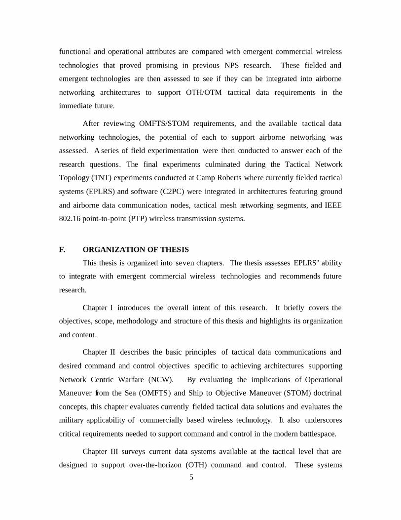
D. SYSTEM ATTRIBUTES ..............................................................................23 E. EPLRS WAVEFORMS.................................................................................26 F. SOFTWARE...................................................................................................28
1. General ................................................................................................28 2. Operating System...............................................................................28 3. JTRS Compatibility ...........................................................................28
G. WIRELESS NETWORKING COMMUNICATIONS AND CONTROL SERVICES ................................................................................29 1. General ................................................................................................29 2. Coordination Network .......................................................................29
a. Point-to-Point Resource Acquisition......................................30 b. Point-to-Point Relay Acquisition............................................30 c. Address Resolution Protocol...................................................30 d. Network Management Communications................................30
3. Contention Access Multicast Communications Service .................31 a. EPLRS CSMA Networks ........................................................31 b. EPLRS CSMA Employment and QoS....................................31 c. Flood Relay..............................................................................34
4. Dedicated Access Multicast Communications Service ...................35 5. Point-to-Point Communications Service ..........................................35
H. POSITION LOCATION INFORMATION (PLI) FUNCTIONALITY ...35 I. NETWORK MANAGEMENT.....................................................................35
1. Enhanced Network Management Software .....................................36 2. Simple Network Management Protocol (SNMP) ............................37
V. EMERGENT COTS WIRELESS NETWORKING TECHNOLOGIES .............39 A. CHAPTER OVERVIEW ..............................................................................39

ix
B. IEEE 802.11 TECHNOLOGIES ..................................................................39 1. General ................................................................................................39 2. Functional Description ......................................................................39 3. Technical Characteristics ..................................................................40 4. Commercial Applications ..................................................................40 5. Capabilities and Limitations .............................................................41 6. Potential MAGTF Applications ........................................................42
C. IEEE 802.16 STANDARDS...........................................................................42 1. General ................................................................................................42 2. Functional Description ......................................................................42 3. Technical Characteristics ..................................................................43 4. Commercial Applications ..................................................................43 5. Capabilities and Limitations .............................................................44 6. Potential MAGTF Applications of 802.16 .......................................44
D. IEEE 802.20 TECHNOLOGY......................................................................45 1. General ................................................................................................45 2. Functional Description ......................................................................45 3. Technical Characteristics ..................................................................45 4. Commercial Uses................................................................................45 5. Capabilities and Limitations .............................................................46 6. Potential MAGTF Applications for 802.20......................................46
E. MESH ROUTING PROTOCOLS................................................................46 1. General ................................................................................................46 2. Advantages of Meshed Networking ..................................................47 3. Categories of Meshed Network Protocols ........................................49
a. Active vs. Reactive...................................................................50 b. Flat Routing vs. Hierarchical Routing...................................50
4. Overview of Prominent Mesh Protocols ..........................................50 a. Ad hoc On Demand Distance Vector Routing (AODV)........51 b. OLSR .......................................................................................51 c. Topology Broadcast-based Reverse Path Forwarding
(TBRPF)..................................................................................52 5. Potential MAGTF Employment of Mesh Networking Protocols ..53
F. ANALYSIS OF EPLRS VS. COTS WIRELESS NETWORKING CAPABILITIES AND LIMITATIONS.......................................................53 1. IEEE 802.11x ......................................................................................53 2. IEEE 802.16 ........................................................................................54 3. Meshed Network Protocols ...............................................................54 4. Summary.............................................................................................55
G. LEVERAGING MAGTF ASSETS TO SUPPORT TACTICAL WIRELESS.....................................................................................................55 1. Overview.............................................................................................55 2. Airborne Tactical Data Network Gateways ....................................56 3. ATDNG Applicability in Supporting Dominant Maneuver
Warfare ...............................................................................................56

x
4. EPLRS Suitability for ATDNG Employment .................................57 5. Potential Applicability of SADL in ATDNG...................................57 6. To the Future: An EPLRS-based ATDNG Conceptual
Architecture ........................................................................................58
VI. EXPERIMENTATION AND RESULTS ................................................................59 A. EXPERIMENTATION OVERVIEW..........................................................59
1. General ................................................................................................59 2. Tactical Networking Topology Experimentation Environment ....60 3. Application Software .........................................................................61
a. C2PC 5.9.0.3............................................................................61 b. Microsoft NetMeeting .............................................................61 c. Situational Awareness Agent v1.1..........................................61 d. SPEED 9.0.1............................................................................61
4. Test Measurement Software .............................................................61 a. Ixia Chariot .............................................................................61 b. Solarwinds Orion ....................................................................61
5. Test Measurement Methods ..............................................................61 a. Distance...................................................................................62 b. Manual Timing & Throughput Calculations ........................62 c. Measuring EPLRS Network Acquisition (Nodal
Association) .............................................................................62 B. EXPERIMENT 1: MESH AND C2PC PERFORMANCE BASELINE..63
1. Overview.............................................................................................63 2. Objectives............................................................................................63 3. Purpose................................................................................................63 4. Methodology .......................................................................................64 5. Measures of Performance..................................................................65 6. Observations and Results ..................................................................65
C. EXPERIMENT 2: EPLRS CSMA PERFORMANCE BASELINE.........66 1. Overview.............................................................................................66 2. Objective .............................................................................................67 3. Purpose................................................................................................67 4. Methodology .......................................................................................67 5. Observations and Results ..................................................................68
D. EXPERIMENT 3: EPLRS AIRBORNE COMMUNICATIONS NODE RANGE AND ASSOCIATION ........................................................69 1. Overview.............................................................................................69 2. Objectives............................................................................................69 3. Purpose................................................................................................69 4. Methodology .......................................................................................69 5. Observations and Results ..................................................................72
E. EXPERIMENT 4: EPLRS ATDNG INTEGRATION AND PERFORMANCE ..........................................................................................72 1. Overview.............................................................................................72 2. Objectives............................................................................................72

xi
3. Purpose................................................................................................74 4. Methodology .......................................................................................74
a. Experiment Construct .................................................................74 b. Radio Coverage Analysis (RCAs)...............................................74 c. Network Topology........................................................................76
5. Execution.............................................................................................77 6. Observations and Results ..................................................................83
VII. CONCLUSIONS AND FUTURE RESEARCH RECOMMENDATIONS..........85 A. CONCLUSIONS ............................................................................................85 B. FUTURE RESEARCH RECOMMENDATIONS ......................................85
1. EPLRS MSG Networks from ATDNGs...............................................85 2. ATDNG: Joint Force Arial Coverage within the JOA .......................85 3. C2PC Performance in Meshed vs. Wireless Segments .......................86 4. SPEED Analysis of 802.16 COTS Radio Coverage Areas..................86
LIST OF REFERENCES ......................................................................................................87
BIBLIOGRAPHY..................................................................................................................89
INITIAL DISTRIBUTION LIST.........................................................................................91

xii
THIS PAGE INTENTIONALLY LEFT BLANK

xiii
LIST OF FIGURES
Figure 1. Ship to Objective Maneuver (STOM) [from Ref 6] ........................................10 Figure 2. Iridium Mobile Networking Architecture [from Ref 10].................................15 Figure 3. EPLRS USMC Conceptual Employment [From Ref 1] ..................................22 Figure 4. EPLRS Radio Set RT-1720B(C)/G .................................................................24 Figure 5. EPLRS URO ....................................................................................................24 Figure 6. EPLRS Functional Block Diagram [From: Ref 1]...........................................26 Figure 7. EPLRS Waveform Characteristics [From: Ref 1] ...........................................28 Figure 8. Relay Route Determination using the Coordination Network [From: Ref 1]..29 Figure 9. EPLRS CSMA Supporting Marine C2 Network (C2PC & Chat) ...................32 Figure 10. EPLRS CSMA Supporting Marine Fires Network (AFATDS).......................33 Figure 11. EPLRS CSMA Flood Relay [After: Ref 2]......................................................34 Figure 12. EPLRS Enhanced Network Management Software ........................................36 Figure 13. Current IEEE 802.11 Revisions [From Ref 13] ...............................................40 Figure 14. Typical 802.11x Commercial Application Architecture [From Ref 13]..........41 Figure 15. Commercial Utilization of IEEE 802.16 as a Backhaul for 802.11x [From
Ref 13]..............................................................................................................44 Figure 16. Simple Star Network Topology .......................................................................47 Figure 17. Network Topology Using Meshed Networking Protocol ................................48 Figure 18. Meshed Network Elasticity..............................................................................49 Figure 19. Maximum Elasticity in an IEEE 802.11x Meshed Network............................49 Figure 20. USAF SADL Architecture [from Ref 1]..........................................................57 Figure 21. Conceptual Architecture for EPLRS ATDNG Integration..............................58 Figure 22. WAN Environment for EPLRS TNT Experimentation...................................60 Figure 23. Meshed Network Client Testing Diagram.......................................................64 Figure 24. EPLRS CSMA Architecture Supporting Baseline Experimentation...............68 Figure 25. CIRPAS Pelican Serving as a Surrogate UAV for ATDNG
Experimentation...............................................................................................70 Figure 26. EPLRS Payload Mount for ACN and ATDNG Experimentation ...................70 Figure 27. EPLRS UHF Blade Antenna Mount on Pelican (UAV Surrogate) .................71 Figure 28. EPLRS ATDNG Construct for Experiment 4..................................................75 Figure 29. EPLRS ATDNG Link Analysis Conducted with SPEED ...............................75 Figure 30. EPLRS RCA Analysis for LRV and TOC Conducted with SPEED...............76 Figure 31. EPLRS RCA Analysis from ATDNG Conducted with SPEED......................77 Figure 32. EPLRS Network Topology Supporting Experiment 4.....................................77 Figure 33. LRV Communications Package for Mesh Bridging ........................................78 Figure 34. EPLRS RT Relocated Mounting for ATDNG Experimentation .....................79 Figure 35. EPLRS ENM Showing Nodal Association prior to ATDNG Availability......80 Figure 36. Solarwinds Nodal Network Monitoring during Experiment 4 ........................80 Figure 37. SA Agent Depicting LRV’s Nodal Network Status at < 1Km........................81 Figure 38. SA Agent Depicting LRV’s Nodal Network Status with ATDNG at 10Km..82 Figure 39. SA Agent Depicting LRV’s Final Position Concluding Experiment 4 ...........83

xiv
THIS PAGE INTENTIONALLY LEFT BLANK

xv
LIST OF TABLES
Table 1. Summary of Fielded, Available, Planned Tactical Data OTH Solutions ........18 Table 2. EPLRS Functional Specifications [After: Ref 1] .............................................25 Table 3. EPLRS Waveform Modes for Version v11.4 [From: Ref 1] ...........................27 Table 4. Functional Attributes of Select Wireless Networking Technologies...............55 Table 5. Measures of Performance for Experiment 1 ....................................................65 Table 6. MEA Test Results ............................................................................................66 Table 7. EPLRS CSMA Baseline Testing Results.........................................................68 Table 8. Measures of Performance for ATDNG Testing (Experiment 4) .....................73 Table 9. Observed EPLRS Data Transfer Rates ............................................................84 Table 10. Summarized Observations Collected during Experiment 4 .............................84

xvi
ACRONYMS AND ABBREVIATIONS aADNS Airborne Automated Digital Network System ACK Acknowledgement ACN Airborne Communications Node ADNS Automated Digital Network System AGL Above Ground Level AFATDS Advanced Field Artillery Tactical Data System AJ Anti-jam AODV Ad hoc On Demand Distance Vectored Routing ARP Address Resolution Protocol ASL Above Sea Level ATDNG Airborne Tactical Data Network Gateway BLOS Beyond Line-of-Sight C2 Command and Control C2PC Command and Control Personal Computer CDMA Code Division Multiple Access CEP Circular Error Probability COF Conduct of Fie COFDM Coded Orthogonal Frequency Division Multiplexing COP Common Operational Picture COTS Commercial off- the-Shelf CSMA Carrier Sense Multiple Access CTP Common Tactical Picture DDS Data Distribution System DII Defense Information Infrastructure DNOC Deployed Network Operations Center DoS Denial of Service EA Electronic Attack \ EMW Expeditionary Maneuver Warfare ENM Enhanced Network Manager EPLRS Enhanced Position Location Reporting System EW Electronic Warfare FDMA Frequency Division Multiplexing FIN Finished GAN Global Area Network GPS Global Positioning System GMF Ground Mobile Forces HNS Host Nation Support ICMP Internet Control Message Protocol IEEE Institute of Electrical and Electronics Engineers IETF Internet Engineering Task Force IP Internet Protocol JTRS Joint Tactical Radio System LOS Line-of-Sight

xvii
LRV Light Reconnaissance Vehicle MAC Media Access Control MANET Mobile Ad Hoc Networking MBWA Mobile Broadband Wireless Access MCTSSA Marine Corps Tactical Systems Support Activity MEA Mesh Enabled Architecture MIB Managed Information Base MGRS Military Grid Reference System MPR Multi-Point Relay MSL Mean Sea Level MSLP Mean Sea Level Pressure NCW Network Centric Warfare NIC Network Interface Card NIST National Institute of Standards and Technology NLOS Non-Line-of-Sight NOC Network Operations Center NPS Naval Postgraduate School OFDM Orthogonal Frequency Division Multiplexing OLOS Optical Line-of-Sight OLSR Optimized Link-State Routing OME Operational Maneuver Elements OMFTS Operational Maneuver from the Sea QoS Quality of Service OSI Open System Interconnection OTH Over-the-Horizon OTM On-the-Move P2MP Point to Multi-Point PCMCIA Personal Computer Memory Card International Association PHY Physical PLI Position Location Information PLRS Position Location Reporting System PoP Point of Presence PTP Point-to-Point RF Radio Frequency RFC Request For Comment RS Radio Set RT Radio Transmitter SA Situational Awareness SADL Situational Awareness Tactical Data Link SATCOM Satellite Communications SBU Sensitive but Unclassified SINCGARS Single Channel Ground and Airborne Radio System SNMP Simple Network Management Protocol SPEED Systems Planning and Engineering Evaluation Device STOM Ship To Objective Maneuver

xviii
SYN Synchronized TACSAT Tactical Satellite TBRPF Topology Based-on Reverse Path Forwarding TCP Transmission Control Protocol TDDS Tactical Data Distribution System TDMA Time Division Multiple Access TOA Time of Arrival TOC Tactical Operations Center TDN Tactical Data Network TNT Tactical Network Topology UAV Unmanned Aerial Vehicle UDP User Datagram Protocol VoIP Voice over Internet Protocol WAN Wide Area Network WAP Wireless Access Point WNW Wireless Network Waveform WIFI Wireless Fidelity WISP Wireless Internet Service Provided

xix
ACKNOWLEDGMENTS
I’ll start with a well-deserved thanks to my former Division G6, LtCol Lloyd
Hamashin who encouraged me to apply for this program and helped make it possible for
me to attend the Naval Postgraduate School. Without his support, I would not have had
this opportunity and the education it has provided.
I would also like to thank Dr. Alex Bordetsky and Dr. Dave Netzer for their
inexhaustible enthusiasm, support, and guidance over the last two years. Their combined
vision, dedication, and involvement in creating and refining the Tactical Networking
Topology series of experimentation continues to provide students an outstanding and
unmatched venue to put ideas into motion.
Thanks also to Ron Russell for his assistance in editing this thesis.
Most of all I’d like to thank my family. To my mom and dad, who have always
been my biggest supporters and greatest teachers, thank you both.
To my wife, partner, and best friend, Adrienne, with whom I have shared so much
for so many years, I can only say thanks for being there for me. I love you, and
appreciate the sacrifices you’ve made along the way.
And to my sons, Levi and Noah, whose smiles and love can move mountains: I
feel so blessed to have you two boys in my life. You’ve always made me proud.

xx
THIS PAGE INTENTIONALLY LEFT BLANK

1
I. INTRODUCTION
A. BACKGROUND
The Enhanced Position Location Reporting System (EPLRS) evolved from the
Position Location Reporting System (PLRS), which began as a Marine Corps command
and control (C2) program in the 1970s. In 1976, the program became a joint
Army/Marine program and began full production in 1983. PLRS’ functional mission was
straightforward. It was designed and built so units could determine their precise location
while maintaining basic situational awareness at a PLRS Master Station located at the
tactical level headquarters.
Determining the positions of individual units was achieved through a fairly
complex system that involved establishing fixed (stationary) reference points within the
deployed architecture, exchanging time-stamped data between multiple nodes, and then
comparing the time of arrival (TOA) of the exchanged data with its time stamp when
received at the receiving nodes. These TOAs, coupled with altitude estimations
determined by barometric pressure and temperature readings taken at each individual
radio, were exchanged throughout the nodal architecture to calculate accurate
geographical positions for each unit. These calculations were based on differential
triangulation and converted to the military grid reference system (MGRS). PLRS was
expensive, bulky, and complex, but it worked. Fully fielded, the system proved to be an
asset in facilitating command and control (C2) in the Gulf War where vast distances and
featureless terrain challenged navigation, orientation, and situational awareness.
Successfully implementing the Global Positioning System (GPS) effectively
fulfilled a vast portion of the PLRS mission and transformed the system from a position
location information (PLI) system to a genuine Tactical Data Radio (TDR). Since PLRS’
PLI calculations involved exchanging data throughout its radio network, and given that it
was a currently fielded system with a proven track record of successfully passing
networked data, PLRS was ideally and adaptively suited to meet the expanded role of
handling emergent tactical C2 data requirements. With its PLI functionality increasingly
viewed as a legacy mission (a back-up to GPS), PLRS radios underwent a series of refits

2
and upgrades, which ultimately resulted in a significantly redesigned system. The
evolved system, the Enhance Position Location Reporting System (EPLRS), was squarely
focused on providing wireless tactical data communications in a mobile environment.
Regrettably, despite its expanded role and the shift in primary missions, the system’s new
name, “EPLRS,” saved all of the letters of its namesake but bears the stigma that name
carries, namely, it is largely misunderstood to be a ground-only, legacy PLI system, with
a dubious mission value, given the proliferation of satellite-based positioning receivers.
With the Department of Defense’s goal of Network Centric Warfare (NCW), its
shifting emphasis toward COTS-based acquisition strategies and the rapid advancements
of commercial wireless transmission and routing capabilities, the future of EPLRS
depends upon its unflagging ability to continue to meet contemporary tactical data
requirements and to integrate with emergent technologies and standards successfully.
Although not a genuine mesh technology, and with modest data rates in comparison to
emergent commercial wireless data networking transmission systems that are produced
to IEEE standards, EPLRS still remains a potent tactical data networking solution. With
superior range, transmission security, and the flexibility of non-directional broadcast
communications and automatic data relay, EPLRS offers a viable tactical Mobile Ad Hoc
Networking (MANET) solution when coupled with Airborne Communication Nodes
(ACNs).
B. OBJECTIVES
This research evaluates the Enhanced Position Location Reporting System’s
tactical data networking capabilities with those found in the commercial sector. The
experimentation compares fielded and emergent technologies within the context of
building flexible and adaptive architectures through airborne communication nodes.
Applying the functional characteristics of each technology to the requirements of Ship to
Objective Maneuver (STOM), and Marine Air-Ground Task Force (MAGTF) tactical
data requirements, this research seeks to evaluate new architectural employment
possibilities that incorporate both EPLRS and COTS networking technologies.
This thesis has two principle objectives: evaluate EPLRS’ ability to interconnect
and route traffic in an architecture that includes meshed networking segments and to
demonstrate an EPLRS-based flexible ad hoc airborne architecture capable of providing

3
Defense Information Infrastructure (DII) access to high mobility maneuver units over-
the-horizon (OTH) and while on-the-move (OTM). Additionally, this research seeks to
determine if current Marine Corps situational awareness (SA) applications, namely,
Command and Control Personal Computer (C2PC), can be used on tactical wireless
networks employing mesh networking protocols, and on tactical network topologies
bridging wired, fielded tactical wireless (i.e., EPLRS) and meshed networking segments.
Collectively, these objectives offer new applications for the EPLRS tactical data
radio in integrating with commercial wireless technologies. Ultimately, this research
may provide tactical commanders with flexible data solutions capable of extending
connectivity to disparate highly mobile “last mile” users who lack either access to
premise infrastructure or current OTH data communication assets, or who are
operationally constrained and unable to employ stationary data transmission equipment.
Finally, this thesis lays the groundwork for future research into the use of EPLRS
in airborne networking, encourages integrating COTS wireless solutions within tactical
military architectures. It invites further exploration in leveraging fielded systems to
create and to develop ad hoc tactical data networks.
C. RESEARCH QUESTIONS
1. Can EPLRS bridge premise wired infrastructure and a commercial wireless mesh networking segment? How does such an architecture impact operational performance?
2. As the principle SA application at the Marine Corps’ tactical level, can C2PC function correctly within a meshed network environment? 3. What are EPLRS’ networking capabilities and limitations compared with those of commercially available networking equipment employing IEEE 802.11x and IEEE 802.16x standards? 4. Can EPLRS. IEEE 802.11x or IEEE 802.16x be used effectively from Airborne Communication Nodes (ACNs) to provide OTH data connectivity to high mobility maneuver units?

4
D. SCOPE
The scope of this thesis, purposefully broad, intends to stimulate further study into
“last mile” tactical data solutions that focus on integrating currently fielded tactical data
solutions with emergent wireless networking technologies. Multi-disciplinary in nature,
this thesis:
1. discusses current tactical data requirements inherent to the tenants of Operational Maneuver from the Sea (OMFTS) and Ship to Objective Maneuver (STOM) pursuant to the Marine Corps’ emphasis on dominant maneuver, 2. reviews currently fielded or planned OTH data communication solutions available to Marine Corps tactical maneuver units, focusing on their functional capabilities and limitations,
3. examines EPLRS’ transmission and routing capabilities, its current conceptual employment, and typical deployment configurations within the operational forces,
4. reviews emergent commercial wireless data networking technologies, specifically meshed routing protocols and IEEE’s 802.11x and 802.16 networking standards, and an overview of their functiona l characteristics and limitations,
5. compares COTS-based wireless data system capabilities to those of EPLRS,
6. introduces the Airborne Tactical Data Network Gateway (ATDNG) concept that assesses EPLRS and COTS wireless data systems’ suitability, independently or cooperatively to provide tactical maneuver units with an airborne ad hoc networking capability that provides DII connectivity.
E. METHODOLOGY
The methodology of this thesis consists of research, discussion, analysis, and
experimentation. Specifically, this thesis first explores the Marine Corps tactical data
requirements regarding doctrine and maneuver warfare and assesses the desirable
attributes, characteristics, and military requirements for such communications.
Next, currently employed OTH tactical data solutions currently available and
employed at the Marine Corps tactical level (regiment and below) are researched and
evaluated. Each solution is assessed to determine how its capabilities and limitations
meet the maneuver units’ requirements. Then current architectural employment,
technical operation, and functional capabilities of EPLRS are examined. EPLRS
5
functional and operational attributes are compared with emergent commercial wireless
technologies that proved promising in previous NPS research. These fielded and
emergent technologies are then assessed to see if they can be integrated into airborne
networking architectures to support OTH/OTM tactical data requirements in the
immediate future.
After reviewing OMFTS/STOM requirements, and the available tactical data
networking technologies, the potential of each to support airborne networking was
assessed. A series of field experimentation were then conducted to answer each of the
research questions. The final experiments culminated during the Tactical Network
Topology (TNT) experiments conducted at Camp Roberts where currently fielded tactical
systems (EPLRS) and software (C2PC) were integrated in architectures featuring ground
and airborne data communication nodes, tactical mesh networking segments, and IEEE
802.16 point-to-point (PTP) wireless transmission systems.
F. ORGANIZATION OF THESIS
This thesis is organized into seven chapters. The thesis assesses EPLRS’ ability
to integrate with emergent commercial wireless technologies and recommends future
research.
Chapter I introduces the overall intent of this research. It briefly covers the
objectives, scope, methodology and structure of this thesis and highlights its organization
and content.
Chapter II describes the basic principles of tactical data communications and
desired command and control objectives specific to achieving architectures supporting
Network Centric Warfare (NCW). By evaluating the implications of Operational
Maneuver from the Sea (OMFTS) and Ship to Objective Maneuver (STOM) doctrinal
concepts, this chapter evaluates currently fielded tactical data solutions and evaluates the
military applicability of commercially based wireless technology. It also underscores
critical requirements needed to support command and control in the modern battlespace.
Chapter III surveys current data systems available at the tactical level that are
designed to support over-the-horizon (OTH) command and control. These systems

6
provide background information and compare alternative employment options and
architectures offered by both EPLRS and emergent COTS wireless networking solutions.
Chapter IV provides a technical overview of EPLRS as a wireless tactical data
radio. It describes the system’s characteristics, functional capabilities, and operation and
compares them with those of emergent networking technologies in subsequent chapters.
Chapter V examines commercial wireless networking technologies and standards
that have the potential to replace, augment, or adapt to military tactical applications in the
pursuit of Network Centric Warfare (NCW). This chapter compares and analyses the
most promising commercial networking technologies’ capability sets with those of the
EPLRS. It also evaluates their potential for integration and adaptation to meet current
tactical data networking requirements. Additionally, this chapter introduces the concept
of the Airborne Tactical Data Network Gateway (ATDNG). It addresses past research
and experimentation of airborne networking and data relay, on-going efforts in these
areas, and evaluates the potential of future architectures integrating either EPLRS or
commercially available wireless networking solutions.
Chapter VI details EPLRS’ suitability to be effectively employed in an ATDNG
architecture, evaluates its ability to associate with available network nodes autonomously
to overcome LOS limitations, and demonstrates its performance in integrating with
tactically deployed meshed networks. Lastly, it summarizes the conduct of those
experiments and documents the results.
Chapter VII provides conclusions on the research conducted in this thesis.
Additionally, it recommends areas for future research and examination.

7
II. CONTEMPORARY TACTICAL DATA REQUIREMENTS
A. INTRODUCTION
The following command and control topics are examined because they are key
considerations in evaluating the success and military applicability of systems,
architectures, and technologies presented later in this thesis. Combined with a look at the
driving philosophy and doctrine behind the Marine Corps approach to warfighting, we
can distill the most critical elements comprising modern tactical data requirements. These
principles, concepts, and requirements provide a perspective on the technical and
functional assessments contained in this thesis and a serve as a backdrop for selected
experimentation and conclusions.
B. PRINCIPLES OF COMMAND AND CONTROL
1. Top-Down Guiding Principles
Today’s military seeks to achieve tactical, operational, and strategic advantages
through information dominance, a goal enabled through Network Centric Warfare
(NCW).
a. Information Dominance
From the perspective of a decision cycle, all military actions are
predicated upon the ability of commanders at each echelon to observe their environment
acurately, correctly access the overall context of the situation, and make sound decisions.
The simplest model of this cycle is provided by John Boyd’s OODA loop: observe,
orient, decide and act. Observation and orientation are dependent not only upon the flow
of information from sensor to shooter, but also cooperative situational awareness
developed from shooter to shooter. From this perspective, we can see that information
superiority hinges upon the ability to pass critical information throughout the battlespace
not only more quickly than the enemy, but more completely (sensor to shooter, shooter to
shooter, and across the levels of war). When our information is gathered more swiftly
and comprehens ively than our adversary, we can achieve information dominance.
b. Network Centric Warfare
Network Centric Warfare (NCW) can greatly enhance the speed and
completeness of information on the battlefield, enable an environment conducive to

8
information superiority, and maximize our potential to achieve information dominance.
Central to NCW is the ability to link each entity within the battlespace to create virtual
organizations. One of the goals visualized in NCW is to erase traditional lines drawn
between the tactical, operational, and strategic levels of war.[Ref 4] To be effective
systems supporting NCW’s vision must be “end-to-end” and link “last mile” users with
operational and strategic assets and information far from the tactical environment.
2. Commonly Desired Characteristics in C4I Systems
Achieving information dominance through Network Centric Warfare requires C4I
systems capable of meeting the elemental characteristics for effective Command and
Control Support (C2S). Six of the most essential qualities are that systems are reliable,
secure, timely, flexible, interoperable, and survivable.
a. Reliability
C4I systems must be reliable to be effective. This characteristic is
generally defined as being available when needed and having a low fa ilure rate.
Regarding this thesis, reliability will entail availability (data connectivity) and Quality of
Service (QoS).
b. Security
Secure communications are essential for effective military employment
and for proper operational security (OPSEC). To meet tactical data requirements systems
must maintain confidentiality, integrity, and authenticity for the information they process
and disseminate.
c. Timeliness
Tactical information is perishable. To achieve information superiority
tactical data must be quickly disseminated. For this thesis, timeliness is not simply
reduced to the networking parameters of latency or achieved throughput. Other essential
elements include the time required to deploy, to set up a communications node, to
configure a network, and to establish communications.
d. Flexibility
The modern battlespace is chaotic, fluid, and ill-suited for complex static
architectures of systems that require manual reconfiguration to respond to changes in the
network’s topology. NDP6 underscores the need of flexible communications by saying,

9
“C4I systems should be capable of being reconfigured quickly to respond to rapidly
changing environments.” [Ref 5]
e. Interoperability
Interoperability is essential to achieving the goal of NCW. Simply put,
systems must be able to exchange information and communicate with each other to create
end-to-end links, enable virtual organizations, and bridge tactical, operational, and
strategic information resources.
f. Survivability
C4I systems must be able to survive in an operational environment.
Beyond the physical tolerance to heat, vibration, moisture, and shock, systems must be
able to adapt to the potential loss of other nodes and operate effectively under Electronic
Warfare (EW) conditions.
C. DOMINANT MANEUVER IN EXPEDITIONARY WARFARE
Information dominance is only one aspect of the overarching vision of “Full
Spectrum Dominance,” articulated in Joint Vision 2020. Dominant Maneuver is another
component in achieving this end-state and best characterized by two operational concepts
embraced by the Navy-Marine Corps team. These are Operational Maneuver from the
Sea (OMFTS) and its tactical application, Ship to Objective Maneuver (STOM).
1. Operational Maneuver from the Sea (OMFTS)
OMFTS is based on the premise that the traditional force-on-force warfare
characterized by the amphibious operations of World War II can (and should) be replaced
by applying maneuver warfare. [Ref 8] Contrary to traditional assaults that pit friendly
forces directly against enemy strongholds established along the beach and engaging in
attrition warfare, OMFTS advocates bypassing these coastal positions. This is done by
transferring combat power over-the-horizon (OTH) deep into the littorals behind enemy
lines. Accomplished with helicopter and tilt-winged aircraft such as the V-22, combat
power is projected far beyond line-of-sight (LOS) using small highly mobile forces
carrying minimal organic firepower and logistic capabilities. Operating against the
enemy’s enabling infrastructure (C2 nodes, communications assets, supply caches and
logistics train), Marines operating ashore would avoid directly confronting the bulk of the

10
enemy’s combat power ashore and would erode their ability to maintain an effective
frontage along the coast.
The advantages enabled through OMFTS presents a significant C2 challenge.
Because the maneuver units are small and have limited assets, they rely heavily on
sustaining fires and logistical support provided from sea-based platforms, but they
operate OTH and OTM.
2. Ship to Objective Maneuver
The Marines’ OMTFS maneuver concept is embodied by the derivative tenant of
Ship to Objective Maneuver (STOM) and is graphically depicted in Figure 1 below.
Clearly, this concept mandates effective and flexible data communication solutions that
support OTM and OTH connectivity.
Figure 1. Ship to Objective Maneuver (STOM) [from Ref 6]
As defined by USJFCOM, STOM is “the concept of maneuvering landing forces
directly to objectives ashore in order to avoid the necessity of establishing a beachhead
and avoiding enemy defensive efforts.”[Ref 9] In keeping with the tenants of OMFTS,
STOM requires maneuver originating from sustained sea-based platforms located over
the horizon from enemy coastal fortifications (25Nm) to objectives deep within the

11
enemy’s rear area (up to 175Nm). STOM is characterized by high mobility, great
distances, with OTM and OTH connectivity requirements, and presents a significant
challenge to maintaining networked communications between forces afloat and ashore.
3. Implications for Marine Corps Tactical Data Communications
To meet the requirements of STOM and NCW, Marine Corps tactical data
communications must be able to bridge between forces afloat and those ashore. Although
Conduct of Fire (COF) voice radio nets can meet the minimum C2 requirements for
coordinating fire support, NCW demands more robust communications. Situational
awareness applications such at Command and Control Personal Computer (C2PC), fire
support applications such as AFATDS, and the demand for efficient “just in time”
logistical support dictate a need for sustained data communications links able to support
continuing operations in a large dynamic environments.
D. SUMMARY OF HIGH MOBILITY TACTICAL DATA REQUIREMENTS
From the principles, characteristics, and doctrines discussed, five elements are
essential to meeting the NCW tactical data requirements of high mobility maneuver units
and supporting OMFTS and STOM. These are the ability to sustain OTH
communications, to provide OTM capabilities, to create large flexible network service
areas, to ensure secure communications, and to maximize network autonomy.
1. Over the Horizon (OTH) Network Connectivity
STOM and OMFTS mandate OTH connectivity. Starting from sea-based
sustainment platforms located upward0 of 25Nm from costal defenses, LOS dependant
communications will be lost prior to ground-based operational maneuver elements
(OMEs) reaching shore. Systems that do not accommodate OTH connectivity will not
meet the basic requirements presented in the STOM scenario and will be unable to
support dominant maneuver.
2. On the Move (OTM) Networking Capabilities
Maintaining information superiority in the fast paced environment characterized
by expeditionary maneuver warfare (EMW) creates the need for networked solutions that
can be employed by OTH and OTM. In STOM and OMFTS both OMEs and sea-based
assets are in nearly continuous motion. Pausing to deploy, orient, and align directional
antenna assets is counter to the implicit objectives of STOM, OMFTS and hinder the

12
ability to achieve dominant maneuver. Marine data communication solutions must have
either omni-directional or self-tracking antennas, must remain in a deployed
configuration for the duration of operations, and must remain operational while mobile.
3. Large Flexible Coverage Areas
The battlespace presented by OMFTS and STOM are immense and do not favor
“spot” or “sectored” data coverage areas. Solutions must be ubiquitous and provide
broad coverage areas that enable flexibility of maneuver throughout the area of
operations.
4. Secure Communications
In all military operations, operational security (OPSEC) is paramount. Any
employed system or solution should provide not only transmission security, but should
also offer a low probability of interception and detection to prevent enemy direction
finding (DF) or signals exploitation. Additionally, tactical networking solutions should
be resistant to EW jamming or denial of service (DoS) attacks.
5. Maximization of Autonomous Netwo rking
Because the OMFTS and STOM environment is fluid, and the loss of OMEs is
always a distinct possibility in any conflict, tactical data network solutions must be as
autonomous as possible. The ability of the system to self-organize, self-heal, and to
establish alternate or redundant paths between networked entities is optimal in such an
environment. Any employed system should minimize user configuration requirements or
administrative management to the extent possible. Complex hierarchical point-to-point
(PTP) systems offer nodal vulnerabilities and present the potential to sever the most
forward deployed assets from supporting C2 information structure and resources.

13
III. OVERVIEW OF CURRENTLY AVAILABLE AND PLANNED OVER-THE-HORIZON (OTH) TACTICAL DATA SOLUTIONS
A. INTRODUCTION
The Marine Corps has recognized that its current inventory of OTH tactical data
networking solutions is insufficient to meet the requirements of NCW while adhering to
the fundamental tenants of expeditionary operations and maneuver warfare. Although the
Joint Tactical Radio System (JTRS) promises to better address these needs with its
Wideband Networking Waveform (WNW), it is widely acknowledged that the JTRS
program will not be providing any sustentative operational capability prior to FY’09.
This reality has engendered a host of interim solutions and initiatives.
The augmentation of commercial satellite assets in OEF and OIF and the recent
Command and Control On the move Network Digital Over the horizon Relay
(CONDOR) initiative highlight efforts to address OTH data networking shortfalls at the
tactical level. This section reviews basic capability sets of systems that are available (or
will soon be) to the Marine Corp’s operating forces in meeting OTH tactical data
connectivity requirements.
B. HIGH FREQUENCY (HF) DATA SYSTEMS
1. HFMR
The High-Frequency Man-pack Radio (HFMR), designated the AN/PRC-150 and
a member of the Falcon II radio family, provides one OTH data solution for tactical
maneuver units operating in the littorals. Rated at distances in excess of 20Nm+, the
HFMR radio supports wireless point-to-point (PTP) data connections, is National
Security Agency (NSA) type 1 certified, and features Automatic Link Establishment
(ALE) to hedge against atmospheric conditions that typically hinder HF communications.
Using MIL-STD-188-110B, the radio’s nominal data rates are 9600 and 2400bps for
uncoded and coded data transmission (respectively). Operationally, this solution
provides sufficient bandwidth to facilitate basic “when required” network connectivity
supporting SA functionality and accommodates the transfer of small (< 500K) data files.
In conjunction with available multi-port interface devices, such as Harris Corporation’s
RF-6010 Tactical Network Access Hub, the system can support four network nodes per

14
hub, by providing a premise wired interface for remote users. Although this system can
provide basic OTH/OTM data connectivity, it has several limitations, including the
relatively unreliable transmission medium provided by HF communications, low secure
data rates (nominally 2400 bps), non-persistent data connections, and architectures built
on PTP or hub and spoke topologies. Additionally, the system has no internal routing
capabilities and presents significant emissions control (EMCON) risks.
2. MRC-138
Like the HHMR, the MRC-138 requires ancillary equipment to achieve a tactical
data network capability. It is essentially a PTP system, employs FSK, and has a nominal
throughput of 2400 bps, although results personally observed in past exercises is typically
around 300 bps. This is however an older analog system, does not have ALE, and is
targeted as the first of the Marine’s currently maintained ground communications
equipment to be replaced by JTRS-GV. Other than the differences listed above, the
capabilities of this system fall well below that of the HFMR. This system’s limitations
are consistent with those previously addressed.
C. SATELLITE-BASED SYSTEMS
Satellite-based systems have emerged as the solution of choice in answering OTH
tactical data network access on the modern battlefield. Two types of systems are
generally available to OMEs: military tactical satellites (TACSAT) and commercial
satellites (COMSAT). Both TACSAT and COMSAT offer the flexibility of expansive
coverage areas, superb reliability, and low probability of detection or interception
(LPD/LPI). Throughput, OTM capabilities, and other utilization characteristics vary by
service.
1. Military Tactical Satellite (TACSAT)
The principle TACSAT system found at the Marine Corps tactical level is the
AN/PSC-5. The concept of employment for the PSC-5, as stated by
MARCORSYSCOM’s PM122, is to provide elements of the MAGTF with a primary
TACSAT C2 capability for “communicating critical information over long distances and
to overcome intervening terrain. ”1 Nominal data rates using 5kHz Demand Access
1 MARCORSYSCOM PMM122 Website http://www.marcorsyscom.usmc.mil/sites/pmcomm/psc5.asp

15
Multiple Assignment (DAMA) is 2400 bps. Like the HF systems , network access is “as
required” and network connections are not as persistent nor as transparent as those in the
commercial wireless networking devices introduced in Chapter V. Resource allocation at
the lowest levels of command can also be problematic. TACSAT channel availability is
recognized as a scarce resource with the possibility of denial of access requests and
preemption. 2 OTM connectivity with TACSAT is not supported.
2. Leased Commercial Satellite (COMSAT)
Because the high demand for TACSAT is unfulfilled due to the limited
availability of channels within the system’s space segment, leased use of COMSAT has
been required to satisfy mission needs. Three of the more prevalent systems found at the
tactical level with OMEs and which are representative of the group include Iridium,
INMARSAT, and Global Star.
a. Iridium
Established as a commercial venture with a primary focus of servicing the
DoD, Iridium offers a range of services that have been employed at the tactical level.
Using a handheld satellite phone, the system is fairly mobile in that the antenna does not
require a precise orientation like TACSAT. Typical of commercially based satellite
service solutions, the system works in a hub-spoke configuration, connecting disparate
users on the ground through satellite relay with a networked gateway. This is
representative of the COMSAT solution set and depicted in Figure 2.
Figure 2. Iridium Mobile Networking Architecture [from Ref 10]
2 MJCS 63-89 and CJCSI 6251.01A dated 21 April 2003

16
Using data compression, Iridium advertises uncoded data rates of 10
Kbps.3 Adding security to the equation, such as with the Enhanced Mobile Satellite
Service (EMSS) application, drops the nominal data rate to 2400 bps but provides NSA
certified type I encryption and direct access to the Defense Information Infrastructure
(DII). Iridium provided an instrumental stop-gap measure in meeting OTH and OTM
data limitations supporting SA during OIF:
The 1st Marine Division G-6 began the procurement of IRIDIUM Telephones (at approximately $4000 per phone to include the secure sleeve) in the summer of 02. Initially 6 IRIDIUM phones were procured to support the CG, ADC, 1st, 5th, 7th, and 11th Marine Commanding Officers. Over the next several months many more phones were procured to the point that the 1st Marine Division (Rein) had 77 IRIDIUM Phones in use to support of the Division. These phones were instrumental in augmenting tactical communication support. At times, due to the limitations of tactical equipment not being able to operate on the move (i.e. SMART-T, UHF TACSAT, and HF Radio Communications), IRIDIUM phones and Blue Force Tracker were the only available means of communications until units stopped and had the time to set up their tactical communications equipment. [Ref 11]
b. INMARSAT
The oldest of the leased commercial services, INMARSAT is another
option to meeting tactical OTH connectivity requirements. Like Iridium, it features low
data rate (LDR) data connectivity at 2400 bps on older terminal sets. However, new
technological advances within the system have emerged as the Global Area Network
(GAN) terminal equipment. GAN nominally supports 64Kbps data connectivity and can
be “bonded” with a second GAN terminal to support OTH wireless network connectivity
at 128Kbps. These systems are not intended for OTM data connectivity and do not
provide secure communications.
c. Global Star
Global Star is the newest lease-available commercial satellite system that
could support STOM tactical data requirements. Its system uses CDMA coding and
features “multi-path” diversity (connecting to two to four satellites per call) to provide
link redundancy. With an uncoded data rate of 9600 baud, Global Star can support non-
secure OTH and OTM communications data communications.
3 Iridium Website

17
D. JOINT TACTICAL RADIO SYSTEM (JTRS)
The Joint Tactical Radio System (JTRS) is envisioned to provide the networking
hardware required to achieve NCW and enable information dominance. JTRS, designed
to replace many of the current tactical data networking solutions discussed, should
provide capabilities better suited to meet the demands of OTH/OTM data
communications. JTRS promises significant increases in data throughput, improved
network integration between wireless and wired segments, and will greatly enhance
interoperability between the services. Unfortunately, JTRS operational implementation is
still several years away. Its initial operational capability, directly targeting the
replacement of the MRC-138 is planned for 2007. Full operational fielding and
capability is not expected until 2020. [Ref 9]
E. COMMAND AND CONTROL ON THE MOVE NETWORK DIGITAL OVER THE HORIZON RELAY (CONDOR)
1. CONDOR Requirement
With JTRS implementation still on the horizon, the CONDOR program has been
conceived and pursued by the Marine Corps to improve ground C2 at the tactical level.
The existence of this program validates two key points central to this thesis. First, the
CONDOR program illustrates that the Marine Corps’ tenants of dominant maneuver and
pursuit of NCW mandate requirements for OTH and OTM command and control
capabilities. Secondly, CONDOR acknowledges that current data solutions do not
sufficiently meet these tactical data requirements.
2. CONDOR Conceptual Employment
CONDOR is primarily a data network gateway system aimed at extending data
communications forward and maintaining situation awareness for tactical commanders
operating in BLOS conditions. The Marine Corps System Command describes the
concept of employment as one that “allows force commanders to maintain situational
awareness of forces BLOS and OTR4 thereby enabling them to accomplish missions
without pausing within LOS radio range to maintain network connectivity.” [Ref 5] This
4 This is believed to equate to “On the Road” and equivalent of the more familiar “OTM” acronym.

18
is further amplified by defining the capability set required for operational success as
being able “to extend tactical data radios BLOS, allow any tactical radio to enter the data
network and allow servers to maintain state while moving”. [ibid]
3. CONDOR Capability Sets
CONDOR is an integration of systems developed to provide a tactical data
gateway for OMEs operating OTH and BLOS from the principle command structure and
access into their networking infrastructure (typically provided with via strategic GMF
assets or Host Nation Support). As such, CONDOR’s capabilities are directly tied to the
supporting systems it employs to achieve wireless connectivity. Even though the system
carries a broad range of wireless transmission systems including EPLRS, its primary
OTH backhaul capability is provide by bonded INMARSAT data terminals. Nominally,
this system can achieve network connectivity at 128Kbps.
F. SUMMARY
Examined from their suitability to support STOM and NCW, the current and
planned future inventory of OTH tactical data network solutions each have suboptimal
characteristics. Although each is capable of supporting OTH communications, several
are unable to provide OTM connectivity. Those that can provide OTM connectivity
either do not support persistent network connections, have security issues, or feature little
or no autonomous networking capability. Table 1 depicts the general characteristics of
the discussed systems as documented by product specifications and assessed by the
author.
Table 1. Summary of Fielded, Available, Planned Tactical Data OTH Solutions

19
One fielded system not specifically designed to provide OTH tactical data
networking capabilities and which has not been included in Table 1 is the Enhanced
Position Location Reporting System (EPLRS). EPLRS features several communications
services, network configurations, and capabilities. Optimally employed, EPLRS
capabilities would favorably compare with any of the previously assessed solution sets.
Although individual EPLRS links are LOS dependant, the system can automatically relay
data throughout its network and effectively bridge two stations otherwise separated by
terrain. This can be a simple two-hop relay, or multiple hops (up to 6). Because of this
ability to relay traffic throughout its network, its OTM capabilities, high security and
anti-jam (AJ) characteristics, and flexible employment options favorable to autonomous
networking environments, EPLRS offers great potential for the STOM environment.
Chapter IV describes EPLRS in technical detail, setting the stage to examine
opportunities to leverage the system and integrate with emergent networking
technologies.

20
THIS PAGE INTENTIONALLY LEFT BLANK

21
IV. TECHNICAL OVERVIEW OF THE ENHANCED POSITION LOCATION REPORTING SYSTEM (EPLRS)
A. BACKGROUND
As mentioned in the introduction, EPLRS and its role as the Army and Marine
Corps’ “tactical data backbone”5 evolved from the Position Location Reporting System
PLRS). Originally dedicated solely to determining each radio’s relative position to
known reference points within the network, the system exchanged position and time
stamped data to allow individual units to determine their precise geographical position.
The network, and its collective positional information, was controlled and displayed from
the PLRS Master station, which was typically located at the Division Headquarters level.
This provided automated position reporting and provided rudimentary situational
awareness (SA) at the higher levels of command (locations collocated with the master
stations). With the advent of the Global Positioning System, PLRS lost tactical
relevance; however, its functional capability to route data throughout a radio network
made it an ideal candidate to incorporate the TCP/IP API and emerge as a wireless
tactical data communications system dedicated to providing OTM capabilities.
Beginning with v10.x released in FY 2001, EPLRS retained its integral Position Location
Information (PLI) functionality but was now able to route and relay tactical SA data at
nominal data rates of 56Kbps. The Marine Corps currently fielded version, v11.4,
supports 488kps. The most recent software version, available in beta at the time of this
writing, provides waveforms capable of 1Mbps connectivity. Raytheon’s future software
versions plan to incorporate automatic IP addressing, dynamic routing, and true mobile
ad hoc networking (MANET) support. [Ref 12]
B. FUNCTIONAL DESCRIPTION AND CONCEPT OF EMPLOYMENT
The Enhanced Position Location Reporting System provides tactical wireless data
communications and network routing capabilities in a mobile environment. EPLRS
networks can range in size from two to several hundred radios. For the Marine Corps,
the concept of employment for this system is to extend secure tactical data networks from
5 From MCSC PMM122 website

22
the regimental to the battalion level. Additionally, the system provides battalion data
communications down to the company level and establishes network connectivity to
SINCGARS data communications found below the company level, as shown in Figure 3.
Figure 3. EPLRS USMC Conceptual Employment [From Ref 1]
C. EPLRS MULTIPLE ACCESS TECHNIQUES
EPLRS uses numerous multiple access techniques to allow for several units to
access limited resources simultaneously. This allows a great deal of flexibility in
providing a variety of ad-hoc network configurations. These reuse techniques include
Time Division Multiple Access (TDMA), Frequency Division Multiple Access (FMDA),
and Code Division Multiple Access (CDMA).
1. Time Division Multiple Access (TDMA)
At its core, EPLRS uses a TDMA architecture as a mechanism to partition its
communications channel. One EPLRS time slot, either two or four milliseconds in
duration, is designed to wholly encapsulate the functions associated with data
transmission and reception. [Ref 1] By using TDMA, an EPLRS radio can participate in
multiple networks simultaneously and can provide several concurrent communication
services, and thus fulfill several user data requirements with a single radio set.
Time slots are assigned according to specific communications requirements.
Time slots can be reused by multiple radios for several reasons. First, multiple

23
frequencies allow independent use of the same time slots in the same area. Second, the
same time slot and frequency may be reused in different geographical locations, so they
do not conflict. Third, the same time and frequency may be used in the same general area
where spread spectrum coding allows near/far resolution of transmitted signals. This is
especially effective for radio-acknowledged communications services in which the radios
automatically request missed transmissions from the source. In many cases, a group of
time slots are shared by multiple radios, using a bandwidth-on-demand pool of contention
access time slots. [Ibid]
2. Frequency Division Multiple Access (FDMA)
Frequency Division Multiple Access (FDMA) expands the available system
capacity by allowing time reuse (using different frequencies). It also provides a
mechanism for segregating functionally disjointed groups of users located within the
same geographical area of operation. EPLRS’ primary operating frequency band is 420
to 450 MHz. The frequency band is typically divided into six frequency channels to
provide the most discrete frequency channels without mutual interference. This allows
radios in the same area to transmit and to receive any of the six channels on the same
time slots without significant interference. [Ibid]
3. Code Division Multiple Access (CDMA) Techniques
In addition to the TDMA and FDMA multiple access techniques already
described, EPLRS also uses CDMA to enhance gain and to optimize network capacity.
Employing a five Mega Chip Per Second (MCPS) direct sequence spread-spectrum
waveform, the networking protocols used by EPLRS are able to support CDMA and use
unique spread-spectrum codes throughout the network to prevent unintended data capture
and near-far mutual interference. [Ibid]
D. SYSTEM ATTRIBUTES
An EPLRS radio set, the AN/VSQ-2C(V)2, consists of three main components:
the radio transceiver (RT) unit (RT-1720B(C)/G) (depicted in Figure 4) and a small hand-
held user display/data entry unit, known as a user read-out unit (URO), connected to the
RT as needed with a URO cable as depicted in Figure 5, and a man-packed antenna (AS-
3448/PSQ-4). Back-up (cryptographic key) memory is maintained by a traditional 9v

24
Figure 4. EPLRS Radio Set RT-1720B(C)/G
Figure 5. EPLRS URO
“keep alive” battery accessed on the front face plate of the RT. The radio propagates in
the UHF spectrum, hopping through six frequencies between 420 and 450Mhz, and draws
16 watts of power in man-pack configurations drawn from a single BA-5590 or BB-390
battery. Transmission ranges are predominantly LOS dependant with stated “operator
expectations” of 10km for ground-to-ground communications (depending on terrain), and
100km ground to air for OLOS.6 Table 2 provides a summary of EPLRS’ functional
attributes and technical specifications.
6 As provided in the EPLRS Operator’s Handbook from the initial fielding of v10.3

25
Table 2. EPLRS Functional Specifications [After: Ref 1]
Although EPLRS radio sets are fielded with battery boxes and billed as man-
portable, the Marine Corps fielding concept was “a vehicle for every radio.” The
physical appearance of the RT and URO are depicted in Figures 4 and 5. Even though
each RT has a URO, the unit is not necessary to operate the radio; radio configuration
and operation can be monitored and remotely configured by an ENM. A functional block
diagram of the RT is provided in Figure 6.

26
Figure 6. EPLRS Functional Block Diagram [From: Ref 1]
E. EPLRS WAVEFORMS
EPLRS supports a variety of waveforms, each with specific transmission
characteristics and capacities. Conceptually, these are provided in response to potential
enemy EW activity in recognition of the inverse relationship between the security and
availability of communications and throughput. Essentially, the higher the throughput
the more susceptible a signal is to interception, detection, and jamming. Lower data rates
support additional resistance to EW activities and are more resilient to environmental
conditions. By providing a diverse selection of waveform modes, EPLRS allows the
network manager subsequently to select the optimal waveform for the intended
operational environment.
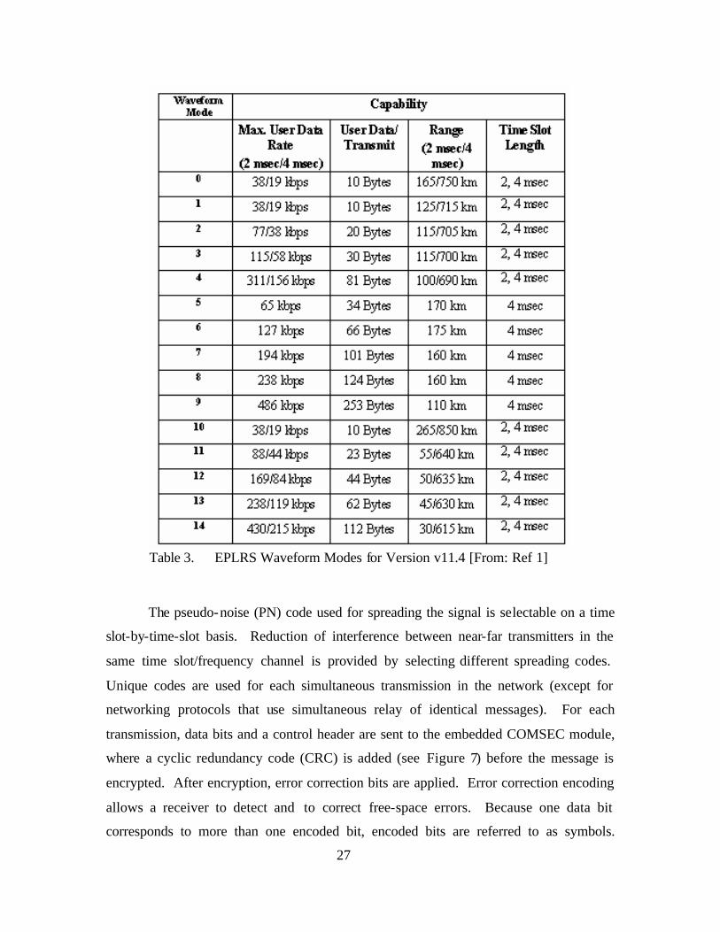
27
Table 3. EPLRS Waveform Modes for Version v11.4 [From: Ref 1]
The pseudo-noise (PN) code used for spreading the signal is selectable on a time
slot-by-time-slot basis. Reduction of interference between near-far transmitters in the
same time slot/frequency channel is provided by selecting different spreading codes.
Unique codes are used for each simultaneous transmission in the network (except for
networking protocols that use simultaneous relay of identical messages). For each
transmission, data bits and a control header are sent to the embedded COMSEC module,
where a cyclic redundancy code (CRC) is added (see Figure 7) before the message is
encrypted. After encryption, error correction bits are applied. Error correction encoding
allows a receiver to detect and to correct free-space errors. Because one data bit
corresponds to more than one encoded bit, encoded bits are referred to as symbols.

28
Symbols are interleaved before transmission to improve performance against burst noise.
Each symbol is transmitted as (or spread over) a number of PN chips. The exact number
of chips per symbol is dependent upon the waveform mode. Spread-spectrum separation
(spreading) provides improved anti-jam (AJ) performance. The burst waveform also
contains certain elements of non-user data (consisting of power rise, preamble, time
refine, buffer and power fall) in the form of additional symbols. [Ibid]
Figure 7. EPLRS Waveform Characteristics [From: Ref 1]
F. SOFTWARE
1. General
EPLRS is software controlled and programmable and can be reconfigured
remotely, over-the-air (OTA), without removing the radio from its operational
environment. Software for the radio is written in the C++/C language and is stored in
non-volatile memory within each radio set.
2. Operating System
The EPLRS software application runs under VxWorks, an embedded real-time,
Posix-compliant COTS operating system. This provides a multi-tasking environment
with standard APIs for other COTS applications such as Transmission Control Protocol
(TCP), Internet Protocol (IP), Point-to-Point Protocol (PTP) and Simple Network
Management Protocol (SNMP). [Ref 1]
3. JTRS Compatibility
Following the OSI standards, the software is layered. The physical layer’s
Application Programming Interface (API) is the JTRS modem API. The JTRS API is
standard throughout employed protocol stacks and allows for both Command Object

29
Request Broker Architecture (CORBA) and Operating System (OS) calls. Using
standards-based vice system specific APIs at the physical level ensures compatibility
with any modem adhering to the same standard.
G. WIRELESS NETWORKING COMMUNICATIONS AND CONTROL
SERVICES
1. General
EPLRS data communications fall into two categories: provisioned
communications services and a coordination network (overhead).
2. Coordination Network
EPLRS uses its coordination network to exchange information (messages)
between radios within the network. These messages are exchanged on a fixed time and
frequency overhead assess the current network topology and route network traffic. In
addition to sending status messages to the ENM (if present), the coordination network is
used to determine IP addresses using Address Resolution Protocol (ARP) and to maintain
PTP circuits. The coordination network includes all radios on a given channel. Figure 8
below depicts Low Data Rate (LDR) path finding performed by the coordination
network. In this example, the coordination network conducts both resource and relay
acquisition to create a virtual circuit. The specific mechanics of this process and the role
of the ENM within the coordination network are explained in paragraphs (a) through (d)
below as documented and explained in reference (1) provided by Raytheon.
Figure 8. Relay Route Determination using the Coordination Network [From: Ref 1]

30
a. Point-to-Point Resource Acquisition
Point-to-Point time/frequency resources are negotiated between endpoints
from the allowable set, as defined by the ENM. Using the mechanism illustrated in
Figure 8, endpoints suggest time/frequency resources to one another in messages sent
over the coordination network. When one endpoint suggests a time frequency resource
(via the coordination network), the other endpoint can accept or reject the suggestion,
depending on its current communication assignments. In either case, a message is sent
back (via the coordination network) to inform the originating endpoint.
b. Point-to-Point Relay Acquisition
Source routing is used to select relays for Point-to-Point circuits. Point-to-
Point relays are negotiated as needed. Using the mechanism illustrated in Figure 8 above,
endpoints transmit relay path finding messages via the coordination network. Prospective
relays retransmit the path finding a message until it reaches the endpoint addressed inside
the message. After receiving the path finding message, the addressed endpoint generates
and transmits a relay acknowledgement message. The relay acknowledgement message
is directed (in reverse order) along the same path that the path finding message traveled,
back to the path finding message originator. Receipt of the relay acknowledgement
message informs a prospective relay that it was chosen to support the circuit.
c. Address Resolution Protocol
Address Resolution Protocol provides a mechanism whereby radios can
match destination IP addresses to EPLRS IDs, giving them the ability to establish
switched virtual circuits for datagram delivery.
d. Network Management Communications
The EPLRS Network Manager (ENM) communicates with radios over the
coordination network. The ENM sends control messages to individual radios, which
respond with status information. This control/status exchange is accomplished in the
same manner as the ARP request/response process. Note that even though the ENM uses
the coordination network to exchange control and status information with individual
radios, more substantial amounts of data (e.g. configuring a radio) are exchanged via
communication services.

31
3. Contention Access Multicast Communications Service
a. EPLRS CSMA Networks
EPLRS Carrier Sense Multiple Access (CSMA) communications service allows
many hosts on a single broadcast network to create and to establish virtual circuits to
exchange data. All RTs assigned to a CSMA network share that circuit’s total available
bandwidth. For v10.3 this would be 56kbps, and for v11.4 this could be up to 486kbps;
however, only one radio is allowed to access the network at any given time.
b. EPLRS CSMA Employment and QoS
Although access to the network is contention based, and quality of service (QoS)
is sacrificed, very little planning is required to configure and to implement a CSMA
network. In low density v10.3 empoyments (less than 30 network nodes), this
communication service can reliably support SA and chat functionality at the SPMAGTF
level.7 Because of the CSMA communication service’s simplicity and effectiveness, it
has become the preferred deployment configuration for Marine units and expanded from
its initial role as a conduit for SA data to additionally providing primary communications
for fire support applications, such as the Advanced Field Artillery Tactical Fire Direction
System (AFATDS). Figures 9 and 10 show two typical CSMA deployment
configurations run concurrently to support a Marine regiment’s C2 and fire support data
networks as executed in a live-fire combined arms exercise.
7 Phone interview with Major Chuck Stevens, USMC (3rd Marine Regiment S-6) conducted January
2005.
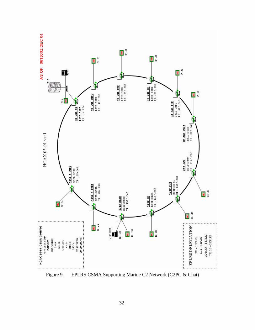
32
Figure 9. EPLRS CSMA Supporting Marine C2 Network (C2PC & Chat)

33
Figure 10. EPLRS CSMA Supporting Marine Fires Network (AFATDS)

34
c. Flood Relay
Flood Relay is the method by which VCs supporting CSMA are
established. Using the ENM when the network is initially established, the number of
hops (relays) can be configured to meet operational requirements. Each hop after the first
involves a relay, which is essentially the rebroadcast of the original transmission. Hops
use time slots, thus deduct from the aggregate bandwidth. In the example provided in
Figure 11 below, Bob sends Joe a message in a CSMA network supporting three relays.
In time slot eight, (LTS 0) transmits his message, which is received by Sam in that same
time slot. On the next time slot (16), the message is then relayed by Sam to Ed. Ed
receives the message in slot 16 and passes it in the next time slot (24) to Joe, the final
(and intended) recipient. From the mechanics of this relay process, the impact on
throughput becomes obvious. In Figure 11, compare the four-hop CSMA transmit (Tx)
and receive (Rx) scheme to that of the single hop (no relay). A one-hop scheme retains
all eight logical time slots for transmission, while a four-hop scheme provides only two,
using the other six for retransmissions. Discounting other factors (such as overhead for
the coordination network), this effectively reduces a nominal 56kbps circuit to 14kbps.
Figure 11. EPLRS CSMA Flood Relay [After: Ref 2]
35
4. Dedicated Access Multicast Communications Service
The Multi Source Group (MSG) is an alternative to the CSMA communications
and provides guaranteed access to the network and ensures speed of service. Although
limited to 16 broadcasting hosts, this service provides contention free access to the
network and avoids bandwidth degradation associated with contention based network
protocols. Typical uses for this communication service would be in a sensor network in
which information from a few sensors would be supported with an MSG circuit to
broadcast information to a large group of hosts without the potential delay that could be
experienced in a saturated CSMA network.
5. Point-to-Point Communications Service
The least flexible but most capable method of transferring larger files is with a
PTP communications service. PTP bandwidth allocations in v11.4 are divided equally
between the two hosts up to the total PTP circuit capacity of 123kbps. PTP relays are
negotiated as required using the coordination network. [Ref 1]
H. POSITION LOCATION INFORMATION (PLI) FUNCTIONALITY
Transmissions within the EPLRS network are time stamped by the originating RS
with the time of transmit so that the receiving station can measure the time of arrival
(TOA). By determining the relative time offset from replies received back at the
originating RS on the return path from the receiving RS, two-way TOA measurements
can be used to determine the slant range between the radios. These position calculations,
coupled with barometric pressure readings taken at each RS and with Mean Sea Level
Pressure (MSLP) and ambient air temperature measurements distributed throughout the
network, establishes vertical positioning and velocity for each RS. Taken with three
known (and stationary) reference points, this information is then used to calculate the
position of each RS within the network +/- 15m.
I. NETWORK MANAGEMENT
EPLRS network management is accomplished primarily with a Windows-based
software application called the Enhanced Network Manager (ENM). This application
provides a graphical user interface (GUI) to configure and to manage EPLRS networks

36
and communication services. Additionally, SNMP support allows for third party
monitoring and management applications.
1. Enhanced Network Management Software
The EPLRS network is configured, controlled, and managed from a Windows-
based software application called the Enhanced Network Manager (ENM), which is
typically run from a standard laptop computer. An ENM can provide network
management capability from any node within the network and is used to define the
network and to configure communications services. Once a network has been initially
established and configured, the ENM can continue to be used to manage and monitor the
network or can be removed entirely without disrupting communications: supported
services between nodes will continue. The system is designed so that individual nodes
that become separated from the network (extended beyond the propagation coverage area
from all other nodes) will automatically associate (rejoin) with the network once they
return within range of any other networked node. This capability provides for flexible
and redundant data connectivity that can quickly adapt to both the presence and location
of individual nodes and can accommodate dynamic changes in network topology.
Figure 12. EPLRS Enhanced Network Management Software

37
2. Simple Network Management Protocol (SNMP)
Because EPLRS employs standardized APIs at the physical layer, it supports
SNMP software tools. SNMP allows for a broad range of network management options,
including fault monitoring, performance monitoring, and resource management.

38
THIS PAGE INTENTIONALLY LEFT BLANK

39
V. EMERGENT COTS WIRELESS NETWORKING TECHNOLOGIES
A. CHAPTER OVERVIEW
This section provides an overview of emergent wireless networking technologies
currently available within the commercial sector. Specifically, this section examines the
functional capabilities and commercial uses of IEEE 802.11x, IEEE 802.16, IEEE
802.20, and prominent meshed networking protocols, and then evaluates the potential of
each in its current state for uses within the MAGTF. This section also compares and
contrasts the capabilities and limitations of employing emergent COTS technologies to
that of EPLRS in a STOM/OMFTS environment. Beyond this, this section examines the
current functional capabilities of each technology and the potential for employment with
ACNs to overcome LOS limitations and better enable OTH and OTM tactical data
connectivity. Finally, this chapter examines the Airborne Tactical Data Network
Gateway (ATDNG) concept and how these existing standards and technologies could be
leveraged by using Airborne Communication Nodes (ACNs).
B. IEEE 802.11 TECHNOLOGIES
1. General
IEEE 802.11x, also called “WiFi” is the most prevalent of the ratified open
standard wireless networking technologies. The goal of the IEEE 802.11 series of
standards is to develop a wireless equivalent of the IEEE 802.3 standard universally used
for wired networks. It also focuses on providing service at the Local Area Network
(LAN) level. As an open standard, IEEE 802.11x has achieved great success in the last
several years with the standards approaching ubiquity in both residential and commercial
sectors.
2. Functional Description
Designed to support wireless client-to-client communications and wireless client
to Access Point (AP) or Base Station (BS), IEEE 802.11 standards target both the
Physical (PHY) and Media Access Control (MAC) layers of the OSI model to ensure
compatibility between various LAN equipment manufactures. The standard was

40
designed for an operational range of 100 meters. Although additional range is possible
(with many vendors claiming AP ranges of over 500 meters) ranges in excess of one
kilometer are usually only achieved with high-gain directional antennas. [Ref 13] Three
major revisions to the PHY of the IEEE 802.11 standard have been released to date:
802.11a at 54Mbps, 802.11b at 11Mbps, and 802.11g at 54Mbps. Even with the addition
of third-party amplifiers, effective operational range has remained below 500 meters,
with most client adaptors limited to less than 300 feet of range.
3. Technical Characteristics
All IEEE 802.11 revisions are contention-based network working solutions that
use a CSMA/CD protocol. Different revisions of the 802.11 standard employ different
modulation techniques and operate in the 2.4Ghz or 5Ghz frequency bands. The best
results in terms of both range and throughput have been obtained with OFDM in the
lower frequency bands (2.4Ghz), as evidenced in the superior performance and rapid
proliferation of the 802.11g standard. Figure 13 summarizes currently released 802.11
standards.
Figure 13. Current IEEE 802.11 Revisions [From Ref 13]
4. Commercial Applications
Wireless Internet Service Providers (WISPs) have primarily been using 802.11
technologies to extend wireless networking service into areas where the installation of
wired service would be either impractical or cost prohibitive. From a WISP AP or BS,
802.11b/g is be used to provide “last mile” connectivity in a focused area known as a
“hot spot.” 802.11a has traditionally been used to provide AP to AP/BS connectivity
with high-gain directional antennas to build a network of interconnected wireless “hot
spots.” [Ref 13]

41
Figure 14 depicts a typical 802.11x architecture supporting commercial
applications. Wireless connectivity between the WISP premise infrastructure and the
localized service area (the back haul) is serviced with 802.11a using high-gain directional
antennas to avoid interference with terminal 802.11b/g segments that provide terminal
service to the customer.
Figure 14. Typical 802.11x Commercial Application Architecture [From Ref 13]
5. Capabilities and Limitations
IEEE 802.11 standards can provide fast (up to 54Mbps) and reliable data
connectivity to multiple users in localized coverage areas serviced by APs. This can be
done quickly and efficiently since there are no wires to run (relative to providing similar
connectivity with CAT 5 LAN cable). It is efficient because IEEE 802.11 is an open
standard, well established, and commercially ubiquitous. However, these wireless
networking standards do have significant limitations.
Because it is contention-based, it has inherent scalability and QoS issues. In an
802.11g segment, a single-user connection at 100 feet from an AP may have over
30Mbps of throughout; however, as the number of users on that segment increases, the
42
throughout drops dramatically due to the overhead required for network control.
Approaching 100 users, throughout could be as low as dialup connections. [Ref 13] QoS
cannot be assured because as with the EPLRS CSMA, all users are effectively competing
for available resources. Additionally, the effective client-side operational range of 300 to
500 feet is limiting. Finally, well documented security concerns exist with 802.11.
6. Potential MAGTF Applications
IEEE 802.11 technology is relatively mature, and within the constraints of its
functional limitations, could have viable MAGTF applications. Using the commercial
model as a template for military use, IEEE 802.11-based network connectivity would be
applied at the lowest tactical levels. Adapting from COTS to specifically address the
security concerns could be a viable solution to provide tactical LANs at and below the
battalion level in environments with low EW activity. Increasing operational range to
1,000 to 2,000 meters would be optimal and could provide tactical extension between
battalion and company echelons in MOUT type scenarios. Detailed research and field
experimentation into such applications (i.e. adapt-from-COTS 802.11x with mesh
networking protocol support for intra-company networking) was conducted in parallel
with this research by Captains Francisco Caceres and Brad Swearingin and should be
available in September 2005.
C. IEEE 802.16 STANDARDS
1. General
The IEEE 802.16 standards, otherwise known as WiMAX, were developed in
response to some of the limitations of the IEEE 802.11x standards. Two primary
revisions have emerged to support both fixed and portable applications : 802.16 and
802.16e respectively. Specifically addressed in the 802.16 standards are optimized
media-access controls for improved QoS, reduction of multi-path interference, and
increased robustness. The net effects of these improvements are increased range, higher
data throughput, greater scalability, and configurations that allow guaranteed QoS. [Ref
13]
2. Functional Description
IEEE has successively ratified three standards of 802.16 prior to the June 2004
adoption of the current standard (officially known as IEEE 802.16-2004). The replaced

43
standards were 802.16, 802.16a, and 802.16-REVD. Despite the numerous revisions, all
of the aforementioned standards are for fixed-site long-haul PTP applications. The next
revision of 802.16, namely IEEE 802.16e, is currently under development and is aimed at
servicing mobile users and allowing them to tie into fixed P2MP APs. IEEE 802.16e is
not expected to be ratified until the second quarter of 2006.8
IEEE 802.16 vendors advertise link capabilities in excess of 50Km and shared
data rates of over 70Mbps. Additionally, these standards claim to provide NLOS
connectivity. [Ref 14]
3. Technical Characteristics
Like IEEE 802.11g, the IEEE 802.16 standards use OFDM in the licensed 2.4Ghz
bands, but also provide unlicensed applications in the 5.8Ghz band. The significant
departure of 802.16 standards from those of 802.11x is that MAC access to the PHY is
scheduled. This scheduling eliminates the potential for collision and maximizes the
efficient use of the available bandwidth. In IEEE 802.11, as in all contention-based
networks, access is controlled by randomly generated delays between the MAC and PHY.
This creates a “best effort” QoS. In contrast, 802.16 assigns individual time slots to each
user. To better accommodate BW allocation, these slots can expand and contract in
duration to meet specific user demands, but each client is ensured access within a cycle to
create a higher QoS. [Ref 14] The standards also provide for higher latency tolerance
stemming from multi-path interference. IEEE 802.16 is build to tolerate ten
microseconds of delay spread vice 900 nanoseconds for 802.11x. This allows for a
larger delay spread and greater usable signal distances. [Ref 13]
4. Commercial Applications
Principally used in conjunction with IEEE 802.11x standards for terminal access
supporting dispersed LANs, the long legs and high throughput of IEEE 802.16 is used to
backhaul Wi-Fi into the wired premise network. Figure 15 below depicts a commercial
use of the standard to support “forward deployed” 802.11 segments.
8 As clarification, in this thesis the generic use of “802.16” refers to the current standard (IEEE
802.16-2004) and “802.16e” denotes the developing revision designed to support mobile networking requirements.

44
Figure 15. Commercial Utilization of IEEE 802.16 as a Backhaul for 802.11x [From Ref 13]
5. Capabilities and Limitations
Although increased throughput and range are key considerations, the primary
advantage of IEEE 802.16 is that it enhances QoS. Still, the increases in range are also
an impressive advancement from what has been available with IEEE 802.11x and present
new possibilities. With almost 50km of range, this standard creates new opportunities for
backhauling localized networks. This was not previously possible with IEEE 802.11a.
Even though 802.16 is a vast improvement over 802.11x, the inherent security concerns
evident in previous standards still exist, and compared to modern tactical equipment, in
its current form 802.16, it is suitable only for unclassified or non-sensitive data
transmission.
6. Potential MAGTF Applications of 802.16
Functionally, IEEE 802.16 applications roughly equate to the capabilities
of terrestrial multi-channel communications (such as the AN/MRC-142A) currently
employed by the Marine Corps but with several magnitudes of throughput and less
security required for a viable tactical application. Typically, terrestrial communications
found at the MAGTF level have less than 1Mps throughput. IEEE 802.16 Metropolitan
Area Network (MAN) solutions have about one-fifth the range but over seventy times the
throughput of tactically employed systems. Adapted to address the inherent security

45
concerns, this technology could have a viable role in linking battalions to regiments and
fulfill what is currently provide by EPLRS, and the AN/MRC-142. Similarly, these
standards could be used in PTP applications processing sensitive but unclassified (SBU)
information in areas that are well controlled by collation forces. Also, these standards
could support Morale Welfare and Recreation (MWR) needs that would potentially free
tactical bandwidth for mission-specific applications.
D. IEEE 802.20 TECHNOLOGY
1. General
Although beyond the original scope of this thesis, IEEE 802.20 was demonstrated
by fellow classmates in parallel with field experimentation conducted to support this
thesis. As an emergent technology that builds upon the progress achieved with the
802.16 standard, IEEE 802.20 deserves a brief discussion of its functional capabilities
and limitations.
2. Functional Description
802.20 has been specifically designed to support TCP/IP communications in a
fully mobile network environment and is targeted as a direct competitor to the developing
IEEE 802.16e standard. 802.20 is a dynamic PTP protocol and envisioned to support
WMAN applications where high-speed trains and automobiles would require rapid hand-
off from backbone ISP nodes. Consequently, it has been optimized at the physical (PHY)
and media access control (MAC) layers to support its envisioned application.
3. Technical Characteristics
Like the developing IEEE 802.16e standard, 802.20 is based on packet switched
technology and employs coded OFMD (COFDM) multiplexing, but operates at lower
frequencies. 802.20 uses frequencies below 3.5Ghz, and supports IP roaming and high-
speed data hand off (respective to supporting nodes) to maintain end-to-end connectivity
with low latency.
4. Commercial Uses
As an emergent technology, 802.20 has not yet been ratified as an IEEE standard
and does not currently exist in a singularly identifiable form within the commercial
sector. However, from the 802.20 working group’s stated objectives and the system’s
46
functional characteristics it can be deduced that this technology will eventually provide
broadband mobile wireless access supporting VoIP and video streaming applications.
5. Capabilities and Limitations
The principle advantages of the developing 802.20 standard are that it supports
the transition of a data circuit (hand-off) at a high nodal velocity and offers very low
latency (<50ms). 802.20 offers relative high throughput. Nominal data rates are in
excess of 1Mbps with some 802.20 developers (e.g. Flarion) claiming throughput in
excess of 3Mbps. The principle disadvantages are that 802.16e (the mobile/mesh
variant of the 802.16 protocol) is at least two years ahead of 802.20 and has gained much
wider commercial backing. Critics of the developing 802.20 standard maintain that other
than the high-speed hand-off capabilities (which they claim has dubious value in the
commercial sector), 802.20 offers no substantive improvement over what is being
developed in 802.16e.
6. Potential MAGTF Applications for 802.20
If the developing 802.20 protocol is standardized and proliferates commercially, it
could offer the MAGTF an attractive backbone between ACNs and ground mobile forces.
Because the system far exceeds IEEE 802.16’s capabilities by supporting nodal hand-off
at velocities in excess of 250Km and retains QoS controls, 802.20 could be an ideal
candidate for opportunistic data backhaul through aircraft supporting OMEs on the
ground. Specifically, the initial capabilities demonstrated in 802.20 appear well-suited to
support military applications that feature numerous fast moving strike aircraft operating
at low altitudes. This capability shows promise in both amphibious assault and OMFTS
operational environments. Potential applications could include OTH connectivity for
MEU elements ashore through close air support (CAS) aircraft.
E. MESH ROUTING PROTOCOLS
1. General
Meshed networking protocols were developed as one of the commercial solutions
created to increase the coverage areas of planned and existing hot spots. When each host
on the network is used as a potential message traffic router, demand on servicing APs
was reduced, and in densely populated client areas, service could be extended to the
edges of the network through other hosted clients. This was done solely to increase the

47
“last mile” coverage area in 802.11x topologies. Meshed networks have been
successfully implemented in several metropolitan commercial applications supporting
emergency rescue equipment and police. One example is Mesh Enabled Architecture
(MEA), a proprietary meshed networking solution based on the IEEE 802.11x standard
and purchased from Meshed Networking by Motorola. It has been successfully
implemented in several cities. This system allows fire, rescue, and law enforcement to
use one another’s wireless clients to hop back into the premise network. The system is
also representative of the military potential and application of such technology.
2. Advantages of Meshe d Networking
Traditionally, network topologies have employed a “star” configuration. In the
center of the network was a router that connected individual clients. All traffic for clients
on a given segment of the network passed through the device (which could be a switch, a
router, or a gateway) located at the center. This is also referred to a “hub-and-spoke”
architecture and is depicted in Figure (16) below.
Figure 16. Simple Star Network Topology
This architecture was simple to implement and understand, but it also created a
single point of failure (the hub in the center). Additionally, the coverage area was limited
to the range of the client’s network adaptors from the center of the network.
In contrast, the meshed network uses each client node to route traffic. This allows
the network clients to interconnect, creating multiple potential data paths that eliminate a
single point of failure when multiple nodes are operating in close proximity. The same

48
nodal structure, depicted in the hub-and-spoke example above, is shown in Figure 17
below using a meshed architecture. Each node now has multiple data paths to other
clients within the segment.
Figure 17. Network Topology Using Meshed Networking Protocol
Meshed architectures also have the ability to “stretch,” using the individual range
of each client’s network adaptor to remain connected to the gateway (which services data
communications to other network segments.) This characteristic is referred to as
“elasticity.” Elasticity provides great flexibility and is one of the principal advantages of
mesh. Individual nodes are not limited to the range of their wireless network adaptor –
they need only to stay in sight of another node with a path back to the gateway.
Additionally, they do not need to remain stationary. Each is free to move about with the
coverage area provided by the other clients and the gateway. This is depicted in Figure
18 below where client “F” has moved beyond its integral ability to connect with the
gateway. In a hub-and-spoke architecture “F” would be unable to pass data to any client
within the network. In the mesh architecture depicted, “F” maintains connectivity with
clients “C” and “D” and thus has data connectivity throughout the network.

49
Figure 18. Meshed Network Elasticity
In theory, the maximum range of the network is transformed from d (the
maximum range of the network adaptor) to (n-1) * d (where n = the number of network
nodes).9 Given a nominal IEEE 802.11x range of 300 feet, our sample topology could
theoretically achieve data connectivity out to a range of 1,800 feet, as depicted in Figure
19.
Figure 19. Maximum Elasticity in an IEEE 802.11x Meshed Network
3. Categories of Meshed Network Protocols
Mesh networking protocols fall into several different categories determined by a
protocol’s functional attributes. The two primary attributes for categorizing meshed
networking protocols are the protocol’s state (active vs. reactive), and how it organizes
9 Bach and Fickle

50
nodes within the network (flat vs. hierarchical). In addition to these two attributes, other
methodologies have been employed to improve the efficiency and scalability of meshed
networks. Many of the newest protocols are hybrids: protocols that are active and
hierarchical but use additional techniques such as Location Assisted Routing (LAR) to
determine optimal data paths.
a. Active vs. Reactive
In the most general terms, mesh protocols are either active or reactive.
Active protocols attempt to maintain a current picture of the network topology by
continuously exchanging and sharing routing information between nodes. This offers the
advantage of having the optimum path pre-determined upon receipt of a user’s data, but
typically uses a sizable amount of the available bandwidth as overhead. Alternatively,
reactive protocols wait until they have data to transmit before beginning the process of
route discovery. This minimizes overhead, but requires route discovery upon receipt of
user data typically resulting in increased latency.
b. Flat Routing vs. Hierarchical Routing
Flat routing implies that every node is a peer to every other node and can
be considered the “conventional” approach for a meshed network.
In hierarchical routing certain nodes are promoted to become the senior
node within a given domain (the other nodes operating in close proximity to the promoted
node). Hierarchical routing structures are typical employed in premise wired networks
with a gateway or border router supporting all external routing for a supported domain.
In dynamic meshed networks, such organizational structure is not as readily employed.
By their nature, meshed networks consist of a group of peers acting collectively to route
traffic. Still, some of the most promising meshed networking protocols include the
capability to create on-demand hierarchies autonomously to improve convergence.
4. Overview of Prominent Mesh Protocols
Although numerous mesh networking protocols have been developed over the last
several years, this thesis presents only three of the most prominent: AODV, OLSR, and
TBRPF. Together these three are generally representative of functional capabilities of
mesh networking protocols, are among the most technically mature, or offer the most
promise for military application.

51
a. Ad hoc On Demand Distance Vector Routing (AODV)
The Ad hoc On Demand Distance Vector (AODV) routing algorithm is a
routing protocol designed for ad hoc mobile networks. A reactive protocol, AODV
builds and maintains routes only as required to support network traffics. AODV is
capable of both unicast and multicast routing and can support basic hierarchical structure
(“trees” between multicast group members.) AODV is loop-free, self-starting, and
capable of scaling to large numbers of mobile nodes.
AODV builds and maintains routes using a route request (RREQ)/ route
reply (RREP) query cycle for neighbor discovery. These messages exchange source and
destination IP data, hop-count, and routing sequence information. Once a route has been
established between source and destination nodes, it will be maintained as long as traffic
between the nodes is being periodically exchanged. Additionally, by using the same
broadcast RREQs employed to create the route, an established route may be optimized if
the source node receives a RREP from another node, indicating an alternate path
featuring a smaller hop-count. Established routes time-out, after a sustained period of
inactivity, are eventually deleted from host routing tables. Future routing requests will
reinitiate route discovery.
AODV is a fairly mature protocol and was eva luated in a side-by-side
comparison with an OLSR protocol in field testing conducted at NPS during Surveillance
and Target Acquisition Network (STAN) experimentation in the spring of 2004. Results
from the experimentation showed that AODV provided workable routing between test
nodes but did not substantively (or conclusively) outperform the other mesh networking
protocols evaluated. [Ref: 17]
b. OLSR
The Optimized Link State Routing Protocol (OLSR) is definitively
defined in RFC 3626 (Oct 2003) and is another mesh networking protocol developed
specifically for mobile ad hoc networks. OLSR can be categorized as both proactive and
hierarchical. It exchanges topology information with other nodes of the network
regularly to maintain routing tables using HELLO messages. Additionally, nodes that
have connectivity to numerous other nodes can be “promoted” (autonomously by the
protocol) to serve as a multipoint relay (MPR). Neighboring nodes may announce MPR

52
information periodically in their control messages to other nodes. This essentially creates
network hubs within the topology and results in a basic hierarchical structure.
OLSR performs route calculations, and the MPRs are used to form the
route from a given node to any destination in the network. Moreover, this protocol uses
the MPRs to facilitate efficient flooding of control messages in the network. Using
MPRs and controlling the extent of flooding through those relay nodes provides two
means of minimizing control overheads and also optimizes available bandwidth. [Ref 18]
c. Topology Broadcast-based Reverse Path Forwarding (TBRPF)
TBRPF is another active link-state routing protocol that runs at the
application layer and is designed specifically to support mobile ad hoc networking
requirements. Using UDP traffic on port 712, TBPRF builds hierarchical hop-by-hop
routes along the shortest paths to each destination by computing source trees (paths to all
reachable nodes) based on partial topology information derived from a modified form of
the Dijkstra algorithm. [Ref 16]
Unlike OLSR and OSPF protocols, TBRPF does not share all routing
information throughout the network. Although capable of reporting full source tree
information to neighboring nodes, each node typically reports only a portion of its source
tree using a combination of periodic and differential updates. This has the effect of
reducing overhead. Overhead is further minimized in the neighbor discovery process.
Discovery is achieved by using differential HELLO messages, which only report changes
to the surrounding topology. Consequently, TBPRF HELLO messages are much smaller
than those of other link state routing protocols. [Ibid]
TBPRF’s optimizations in limiting control traffic appear to offer several
advantages over both AODV and OLSR. In a series of modeling simulations performed
by the IETF MANET Working Group, the following performance comparisons where
noted:
? In every scenario, TBRPF achieved a higher delivery percentage (up to 15% higher) than OLSR. TBRPF also achieved a higher delivery percentage (up to 15% higher) than AODV in all scenarios with no mobility, and in all scenarios using the square (670x670) area with the lower packet rates (2 and 4 packets/s). For the long rectangular

53
(1500x300) area, AODV achieved a higher delivery percentage (up to 5% higher) than TBRPF.
? In every scenario, TBRPF generated less routing control traffic than the
other protocols: up to 60% less than OLSR and up to 48% less than AODV. This is despite the fact that TBRPF sends HELLOs twice as frequently as OLSR.
? In every scenario, TBRPF used the shortest paths (except nearly shortest
in some cases with the higher packet rates). In every scenario, AODV used paths that were 12 to 20% longer on average than TBRPF. 10
5. Potential MAGTF Employment of Mesh Networking Protocols
Meshed networking protocols could be used at any echelon within the MAGTF
but seem best suited for localized employment at the lowest tactical levels. Employment
at the tactical level would minimize control overhead and optimize the “last mile”
advantages of mesh, that is, to extend the range of short-ranged data networking
equipment. With locally dense user populations available at the tactical level, using units
could capitalize on the multiple redundant paths provided by the modest tactical
dispersion characteristic of military operations in urban terrain (MOUT) or leverage the
mesh’s elasticity to extend data connectivity forward or around masking terrain.
Potentially, these protocols could provide or extend squad-or platoon level connectivity
to an OTH backhaul capabilities co- located at the platoon or company level.
F. ANALYSIS OF EPLRS VS. COTS WIRELESS NETWORKING CAPABILITIES AND LIMITATIONS
1. IEEE 802.11x
IEEE 802.11x commercial applications most closely approximate the
functionality of EPLRS as currently employed within the Marine Corps. Both provide
“last mile” data connectivity; however, EPLRS offers much greater range than what is
currently available with 802.11x (miles vs. meters). Although 802.11x has the
advantage of simpler configuration, dramatically greater bandwidth, less latency, and
lower cost, its lack of security makes its value as a system supporting tactical level data
connectivity questionable. Still, the system could be used as a “forward of the firewall”
high-density data feed for tactically perishable information (individual location
10 List quoted from Ref 15

54
reporting). Data security could be provided in the form of user authentication and access
controls. Alternatively, security concerns could be addressed by limiting use to non-
sensitive coordination applications such as was done with the Inter Squad Radio (ISR).
The other major challenge to employing IEEE 802.11x effectively is its limited
range. Even extended with the best meshed networking technology available, 300
hundred meters of range will not meet STOM or OMFTS requirements.
2. IEEE 802.16
IEEE 802.16’s capabilities compare well to those of EPLRS. At first glance, and
discounting obvious security issues, which certainly could be addressed to some degree
with link encryption, 802.16 appears more than capable of meeting or exceeding
STOM/OMFTS requirements. IEEE 802.16 features enormous bandwidth that is several
orders of magnitude beyond what can be achieved in an EPLRS network. Additionally,
advertised 802.16 ranges of 50km (or more) and NLOS operation suggest a strong
potential for STOM or OMFTS application. The case is bolstered by previous NPS
experiments that determined 802.16 was a strong candidate for “adapt from COTs
military application,” and suggested that it would address STOM requirements and
offered the advantages of NLOS operation. This would be coupled with the guaranteed
QoS, ease of configuration, and a terminal cost that is less than a tenth that of an EPLRS
RT,
Despite promising potential – without addressing the immediate issue of security
shortfalls and susceptibility to DoS attack – 802.16 has several key limitations that render
it unsuitable to support OMFTS or STOM data communications, most notably that does
not accommodate nodal movement (i.e. maneuver). Clearly there is potential within
8012.16 for military application, but that potential is limited by 802.16’s inability to
maintain range, throughput, or even LOS communications in a mobile environment.
NLOS operation depends on precision antenna alignment; and even in applications
featuring modest distances of under 5Km, it could take an hour to align the antennas to
achieve data connectivity.
3. Meshed Network Protocols
EPLRS cannot compare to the functionality provided by any of the meshed
networking protocols examined during this research. EPLRS can create a mesh- like

55
capability using a single CSMA on a given guard channel but does not have any IP route
discovery capabilities outside of the broadcast network. EPLRS does have some
elasticity, but it cannot compare with what is possible in a network featuring hundreds of
meshed nodes. EPLRS routing capabilities are its greatest shortfall: It is a statically
routed system dependant upon some level of administrative planning, network
management, and pre-deployment configuration to operate successfully with any
semblance of autonomy.
4. Summary
Each of the reviewed technologies has the potential for “adapt from COTS”
military application, but none can individually address the requirements of
STOM/OMFTS. Also, a common and constraint is evidenced: 802.11x, 802.16, and
EPLRS are all largely LOS dependant. Table 4 below summarizes the functional
attributes of select wireless networking technologies that were discussed.
Table 4. Functional Attributes of Select Wireless Networking Technologies
G. LEVERAGING MAGTF ASSETS TO SUPPORT TACTICAL WIRELESS
1. Overview
Given that each of the technologies examined has unique limitations and none can
independently satisfy the OTH/OTM requirements imposed by STOM and OMFTS, new
cooperative architectural configurations need to be explored.
One of the common challenges evidenced in each of the wireless transmission
systems already discussed is that they are all largely LOS dependant. EPLRS may be
able to route around a hill, or 802.16 employing directional antennas may achieve BLOS

56
connectivity due to OFDM’s resistance to multi-path fading, but in the end the most
limiting factor to the performance of each is LOS.
Using our strike and support aircraft to relay network traffic between ground units
appears a viable method of maximizing the LOS capabilities wireless networking
equipment. Provided that selected systems could operate autonomously, it would be
“transparent” to the pilots during the execution of their primary mission. Wireless
networking equipment, perhaps augmented with meshed networking protocols, could be
affixed to the bottom of all US and coalition aircraft and used to provide opportunistic
data relay as they conducted their primary missions. Potential platforms include
unmanned aerial vehicles (UAVs), bombers, strike aircraft, rotary assets, or ISR assets.
2. Airborne Tactical Data Network Gateways
The term “Airborne Tactical Data Network Gateway” was chosen to describe an
aerial platform fitted with wireless networking equipment capable of routing tactical data
network traffic back into any other infrastructure that provides DII connectivity. This
could be another ground-based node, the developing airborne Automated Data
Networking System (aADNS), or satellite connectivity supported by the ATDNG
platform. ATDNG describes a concept vice a particular equipment string.
3. ATDNG Applicability in Supporting Dominant Maneuver Warfare
The ATDNG concept directly addresses the largest of the tactical data networking
gaps resulting from high-mobility operations: the need for OTH communications.
Doctrinally, OMFTS and STOM create an OTH communications challenges at the
initiation of amphibious operations. Increases in the tactical mobility of assault forces
has exacerbated the problem. New warfighting platforms such as the AAAV and the
Osprey will further compound the problem as units are placed increasingly further from
supporting command and control infrastructure.
By capitalizing on our air superiority, maneuver forces supported with an
ATDNG architecture could significantly extend the range of their data communications
using the MAGTF’s own aviation assets communications. As an example, at five feet
above the ground (the typical height for a man-pack antenna) the radio horizon is under
five miles. By comparison at just 2,000 feet, an aircraft’s radio horizon is over 100Nm.
Assuming two ground-based units had LOS wireless networking equipment capable of

57
transmitting data 100Nm, an ATDNG at 2,000 feet could extend data connectivity
between the two from less than ten miles to nearly 200 miles under optimum conditions.
4. EPLRS Suitability for ATDNG Employment
EPLRS is currently the candidate for ATDNG application and evaluation. As a
fielded system, it is held as a table of equipment (T/E) item by all Marine tactical ground
maneuver forces, offers superior range to the researched COTS solutions, and addresses
the security and environmental concerns associated with deploying wireless tactical data
networks in real-world operations. Though it cannot route traffic, EPLRS can relay
traffic over multiple hops with no special configuration, as discussed in Chapter IV.
EPLRS RTs are not currently fitted on Marine Corps Aviation assets, yet the USAF has
been flying with the EPLRS RTs successfully for several years using these tactical data
radio to provide air to ground connectivity required for their Situational Awareness
Tactical Data Link (SADL). SADL is an air-ground EPLRS application used by both the
USAF and USA as an anti- fratricide measure. Notional SADL deployment is depicted in
Figure 20 below.
Figure 20. USAF SADL Architecture [from Ref 1]
5. Potential Applicability of SADL in ATDNG
What is significant about the SADL program is that it provides the potential for
experimentation with an EPLRS based ATDNG architecture in a joint environment

58
immediately. SADL uses only two of the eight available logical time slots within EPLRS
TDMA multiplexing scheme. With EPLRS v11.4, that translates to a minimum of over
200Kbps of unused bandwidth on each SADL equipped aircraft that could be configured
to support opportunistic data relay in an ATDNG employment.
6. To the Future: An EPLRS-based ATDNG Conceptual Architecture
Figure 21 below depicts an EPLRS-based ATDNG conceptual architecture, which
has been modeled to the experimentation environment supporting the Tactical Network
Topology (TNT) experimentation conducted in May 2005. In this architecture, long-haul
data connectivity (over 50Nm) is supported by an EPLRS-based ATDNG hosted on
either a Combat Air Patrol (CAP) or Close Air Support (CAS) aircraft operating in the
general vicinity of ground maneuver forces’s Light Reconnaissance Vehicle (LRV).
Figure 21. Conceptual Architecture for EPLRS ATDNG Integration

59
VI. EXPERIMENTATION AND RESULTS
A. EXPERIMENTATION OVERVIEW
1. General
Experimentation for this thesis consisted of three initial evaluations conducted at
or in the vicinity of the Naval Postgraduate School’s campus in Monterey, California.
These first experiments provided the building blocks for the final experimentation
conducted during the Tactical Network Topology 5-3 experimentation at Camp Roberts
near Paso Robles, California.
The first experiment was conducted to establish baseline performance of a
commercially available IEEE 802.11-based mesh networking segment and to verify that
the selected demonstration software (C2PC 5.9.0.3) functioned correctly in a meshed
networking environment. Next, the EPLRS CSMA network that would be used for
follow-on ATDNG testing was setup and evaluated in controlled lab environments to
assess stability and baseline throughput performance. The third experiment was
conducted to demonstrate and assess ad hoc nodal association and range performance of
the ATDNG architecture in an EPLRS-only environment. The fourth and final
experiment incorporated all of these elements. This provided an end-to-end test linking
an OTH/OTM high mobility user through an ATDNG and back into a tactical
architecture that included a tactical meshed network segment and multiple IEEE 802.16
data links.
Together, these experiments serve to demonstrate and evaluate a basic mobile ad
hoc networking solution that provides OTH/OTM data connectivity. Conducted in a
diverse field networking environment featuring tactical meshed network segments and
IEEE 802.16 backhauls, these experiments evaluate the performance and integration of
an EPLRS-based ATDNG and demonstrates its capability to meet STOM and OMFTS
C2 requirements.

60
2. Tactical Networking Topology Experimentation Environment
Tactical Network Topology (TNT) experiments provide a forum for research and
an evaluation of emergent broadband and network technologies, which may offer the
potential for future military applications. TNT experiments are performed on a quarterly
basis at Camp Roberts in central California under a cooperative agreement between the
United States Special Operations Command (USSOCOM) and the Naval Postgraduate
School. These experiments focus on the integration of multiple networking systems
linking mobile ground and aerial nodes with deployable and premise command and
control (C2) infrastructure with the goal of developing networked communications
systems supporting collaboration, shared situational awareness (SA), and the
dissemination of Intelligence Surveillance and Reconnaissance (ISR) data.
During TNT experimentation, a wide range of technologies are integrated and
evaluated over the course of several days. Figure 22 below depicts an overview of the
greater network environment into which EPLRS was exercised and evaluated.11
Figure 22. WAN Environment for EPLRS TNT Experimentation
11 Not all of the depicted technologies are exercised simultaneously. EPLRS testing was conducted
from the Pelican UAV and Light Reconnaissance Vehicle (LRV) and the Tactical Operations Center (TOC) nodes. This allowed PTP connectivity between the LRV and the TOC as well as network connectivity to meshed networking segments operating in the vicinity of the TOC.

61
3. Application Software
The following application software was used to support the experimentation for
this thesis:
a. C2PC 5.9.0.3
b. Microsoft NetMeeting
c. Situational Awareness Agent v1.1
d. SPEED 9.0.1
4. Test Measurement Software
Many of the tests performed returned logical vice quantitative results. Data
captured from these types of tests simply reflect if something worked as expected or not
and were identifiable by findings that indicate “Yes/No” or “True/False” results.
a. Ixia Chariot
Ixia Chariot was used to benchmark throughput performance. The
selected script used for network loading was the “Long File Send” that is included with
the benchmarking software. All Ixia Chariot testing was conducted end-to-end to
evaluate throughput actually received at the client workstation (the end-point) over the
established data links.
b. Solarwinds Orion
Solarwinds Orion was used to capture performance metrics on nodal
availability (connectivity), latency, and response times. During lab tests, nodes were
monitored from a single Solarwinds terminal; however, this monitoring was expanded for
the final experimentation. During the fourth experiment, all nodes of interest within the
network, including the IP interfaces of each EPLRS RTs, were monitored from
Solarwinds network monitors located both in the TOC and in the LRV. Default polling
intervals were set for two minutes. In the event of a negative ping response from any
given node, Solarwinds was set to increase the polling interval to every twenty seconds.
The increased polling interval would continue until a response was received at which
time the polling interval would return to once every two minutes.
5. Test Measurement Methods
Some testing required physical measurements of distance or time. This
section provides clarifies and describes the general measurement practices and

62
methodology used for situations or circumstances that could not be directly supported by
test measurement software.
a. Distance
All distances identified in the results reflect two-dimensional linear
measurements that do not include slope calculations for ACN altitude. All
distances are straight line “as the crow flies” measurements determined by GPS
receivers co-located at one of the nodes participating in the test. Error for non-
stationary GPS measurements is typically +/- 20 feet. In some cases, for distances
greater than 5000 meters, OTM measurements have been rounded to the nearest
kilometer.
b. Manual Timing & Throughput Calculations
Due to problems encountered with Ixia’s ability to complete measurement
tests in dynamically changing network topologies, some end-to-end throughput
measurements were taken manually. These were performed with pre-compressed JPEG
image files ranging in size from around 200Kb to 500Kb. File transfers were conducted
using the file transfer utility resident within the Microsoft NetMeeting application. Using
voice connectivity to coordinate between the send ing and receiving nodes, a stopwatch
was started at the sending node when the file transfer was initiated and stopped once the
receiving node reported the complete file had been received. The times could then be
compared with the corresponding files size to determine the average throughput during
that individual test.
c. Measuring EPLRS Network Acquisition (Nodal Association)
The length of time it took for airborne and ground nodes to associate with
the CSMA network was a point of interest during the experimentation; however,
obtaining verifiably accurate results was often problematic. In general, for our
measurement purposes we defined RS association as successful IP resolution and ARP
acknowledgement from the associating node. Some field measurements are based on
averages that reflecting the elapsed time between the ACN's scheduled take-off and the
time either of the ground nodes (usually the LRV) received the first ICMP reply from the
ACN RS. Obviously there are some potential problems with this methodology including
the probability of early (or late) aircraft departures from the airfield, the factoring of

63
varied distance between the airfield and ground nodes, and variations in the time it took
the ACN to achieve an altitude sufficient to support LOS to the ground nodes.
B. EXPERIMENT 1: MESH AND C2PC PERFORMANCE BASELINE
1. Overview
The first experiment was conducted about 15 miles East of the NPS campus in a
rural area. The testing area was in an open area that offered OLOS between nodes and
that was free of other 802.11x wireless devices. This experiment was conducted to verify
that the selected demonstration software, C2PC, would function correctly on a meshed
networking segment. Additionally, this experiment sought to obtain baseline
performance data of Motorola’s Mesh Enabled Architecture (MEA), an emergent
wireless meshed networking solution that was in beta, but that would soon be
commercially available.
2. Objectives
The objectives of this experiment were to:
a. determine the maximum operational range between two non-amplified mesh clients using the PCMCIA WMC 6300 adaptor with the external antenna,
b. measure relative data throughput as a function of distance between two non-
amplified clients using the PCMCIA WMC 6300 adaptor with the external antenna,
c. determine the maximum operational range between two non-amplified mesh
clients relaying between a third (equidistant) client using the PCMCIA WMC 6300 adaptor with the externa l antenna,
d. measure relative data throughput as a function of distance between two non-
amplified clients relaying between a third (equidistant) client using the PCMCIA WMC 6300 adaptor with the external antenna.
e. assess C2PC 5.9.0.3P6 application’s functional performance within the
context of these experiments (that is, to maintain a synchronized client-gateway connection and demonstrate track manipulation).
3. Purpose
This experiment demonstrates the maximum ranges for a MEA’s client-side
prototyped hardware as a COTS “last mile solution” and provides information that can be
used to assess its suitability to meet tactical data network connectivity requirements.

64
The results from this experiment provide performance baseline for follow-on testing in
more complex architectures that integrate OTH/OTM backhaul through an EPLRS
ATDNG.
4. Methodology
For the first portion of this experiment, clients A & B (identified in Figure 23
below) began with 200m of separation from the designated starting point. Client B moved
away from the starting point at 200m intervals, as coordinated by Z (the collection
console collocated with client A). This was done until connectivity between A and B
ould no longer be supported by the MEA network interface adaptor (NIC). At each
increment, the collection console checked the data throughput between clients A and B
using IXIA’s long file-send script. To evaluate C2PC, client A was configured as a
C2PC Gateway and Client B was established as a C2PC client. Both Gateway and Client
operators used C2PC’s connection status icon to monitor at which point the application
reported losing connectivity. Additionally, Solarwinds was run from client A to assist in
fault monitoring and isolation and to chart the performance for clients A and B.
Together, the first portion of this experiment addressed experiment objectives A, B, and
E.
Figure 23. Meshed Network Client Testing Diagram
The second portion of the experiment sought to force the MEA NIC to route
traffic between the nodes and meet the experiment’s remaining objectives and
demonstrate mesh elasticity. To do this, the collection console (Z) was positioned at the
maximum distance between clients A and B that connectivity had been reliably
maintained during the first portion of the experiment. Client B was then positioned 200m
further from this point, thus forcing network traffic between A and B to route through Z.
As in the first portion of the experiment, client B then incrementally increased its

65
distance from client A. At each increment of distance between the clients, the collection
console checked the throughput between A andB using the IXIA application and during
all portions of this experiment all three nodes were kept in- line with one other. As in
the first portion of the experiment client A continued to act as the C2PC Gateway for
client B. To evaluate C2PC’s correct functioning, client B manipulated tracks at each
interval. Throughout the entire portion of the experiment, client A continued to monitor
the network using Solarwinds.
5. Measures of Performance
The measures of performance for this experiment are provided in Table 5 below.
Table 5. Measures of Performance for Experiment 1
6. Observations and Results
Operating Point-to-Point (PTP), MEA was able to maintain data connectivity
reliably between nodes at a distance of 400m. Beyond this range, connectivity became
intermittent and beyond 500m, a connection could not be established. Placing the
collection console (Z) at 400m, MEA successfully routed traffic between the two
connected client nodes. Consistent with the elasticity formula, this extended reliable

66
connectivity to 800m – far beyond what had been achieved by PTP. As expected,
throughput degraded as distance increased. Not surprisingly, throughput was impacted
when data was forced to route through console Z. Depending on the distance, relative
throughput when hopping through a meshed node (i.e. console Z) was 15 to 40% less
than what was achieved by PTP. Still, average throughput between endpoints was
impressive and ranged from a high of over 1Mbps at 200m PTP to a low of 34Kbps at
900m when hopping through another client.
No problems were experienced in running C2PC on the meshed network: All
functionality was retained, and no discernable degradation in performance was observed.
During all portions of the experiment, the C2PC client remained connected and
synchronized with the gateway at any distance that network connectivity was achieved.
Specific MEA test results concerning the throughput and distances achieved are
provided in Table 6.
Table 6. MEA Test Results
C. EXPERIMENT 2: EPLRS CSMA PERFORMANCE BASELINE
1. Overview
Initial EPLRS baseline testing was conducted at the Marine Corps Tactical
Systems Support Activity (MCTSSA) at Camp Pendleton, California. The experiment
was duplicated in the Internet to the Sea Lab at NPS the following month.

67
2. Objective
This experiment sought to establish a performance baseline for a simple EPLRS
CSMA network capable of integrating into an ATDNG architecture. The focus of the
experiment was to measure data throughput between client workstations running the
same C2PC application and network monitoring software used in the first experiment.
Additionally it sought to confirm that an RS could be removed and reintroduced to an
operating CSMA without manual reconfiguration.
3. Purpose
The purpose of this experiment was to compare what had been observed in the
first experiment and future experimentation and to validate that the EPLRS RSs were
correctly configured for follow-on experiments.
4. Methodology
A simple EPLRS CSMA network was established in a laboratory environment
that consisted of three class “C” network segments. The network consisted of four host
terminals with connectivity provided by three EPLRS RSs running software version
v10.3, which had a nominal data rate of 56Kbps. Three of the four clients were
connected by a hub to simulate the mobile user segment of the network (the terminal
equipment that would be used in the LRV planned for TNT). The forth client was
attached directly to the RS that would later be attached to the TOC’s premise router at
Camp Roberts (simulating HHQ where mobile uses could obtain access to the DII). One
of the workstations on the LRV segment hosted a C2PC client (10.0.0.4) and its gateway
was established on the TOC segment’s workstation. The RS planned to be used as the
ATDNG (from the ACN) had no host equipment attached. All UROs were removed
from the EPLRS RSs after verifying the correct configuration and operation of each set.
From the ENM, the radio network was configured to use four of the eight available time
slots and the network power was set to the lowest possible setting (400mw). All of the
equipment used for this experiment was setup on a single table with each of the radios
operating within two meters of the others. This experiment was conducted at MCTSSA
over a two-day period and then repeated at NPS’s Internet to the Sea Lab over several
days. Performance data collected from the IXIA console was averaged over numerous
runs conducted at both sites and compared. Figure 24 depicts the employed network.

68
Figure 24. EPLRS CSMA Architecture Supporting Baseline Experimentation
5. Observations and Results
EPLRS baseline throughput testing showed a fair amount of variation over
numerous tests, which was not unexpected for a contention-based radio network loaded
with two polling software applications (C2PC and Solarwinds Orion). Average
throughput consistently fell approximately 30% below the nominal data rate for an
EPLRS v10.3 network, using four logical time slots. Table 7 provides the averages of
several tests performed over a two-day period at NPS.
Table 7. EPLRS CSMA Baseline Testing Results

69
D. EXPERIMENT 3: EPLRS AIRBORNE COMMUNICATIONS NODE RANGE AND ASSOCIATION
1. Overview
Experiment 3 was conducted to provide an initial estimation of the ranges that
could be expected from EPLRS CSMA when using an ACN, verify the equipment
installation on the host aircraft, and measure the time for nodal association in a real-world
environment. The experiment was conducted on the Monterey Peninsula during a four-
hour period.
2. Objectives
The objectives for this experiment were to:
a. determine the maximum operational range for reliable TCP/IP connection between ground-based client s and an EPLRS radio on an ACN operating at 3000’ ASL,
b. verify the installation and autonomous operational function of the
EPLRS RS in the ACN (as the ATDNG), c. measure nodal association times for an ATDNG as it entered and exited
the operational vicinity of a ground-based EPLRS CSMA.
3. Purpose
This experiment was required to scope the final end-to-end experiment by
providing initial estimates on supportable ranges between ground nodes and an ATDNG
by surveying at the first link in the relay (ground to ACN). Additionally, this experiment
would allow the measurement of ATDNG nodal association times and verify that
installation of the EPLRS RT and antenna was operational and could be used without
pilot intervention or pre-flight configuration.
4. Methodology
This experiment was conducted with the Center for Interdisciplinary Remotely
Piloted Aircraft Studies (CIRPAS) from the Marina Municipal Airport in Marina,
California.
The third EPLRS ATDNG RS was installed inside a CIRPAS “Pelican,” a highly
modified Cessna 337 that served as a UAV surrogate for Experiments 3 and 4 and is
depicted in Figure 25.

70
Figure 25. CIRPAS Pelican Serving as a Surrogate UAV for ATDNG Experimentation
The EPLRS RS was mounted at the bottom of a specially constructed 19”
aluminum equipment rack used to support this and other NPS research planned for TNT
experimentation. The payload rack with the EPLRS RS installed at the bottom is
illustrated in Figure 26.
Figure 26. EPLRS Payload Mount for ACN and ATDNG Experimentation
A Trivec-Avant AV 237-4 UHF/EPLRS blade antenna rated at +4dBi was
installed on the belly of the aircraft and fed to the antenna connector on the faceplate of

71
the RT using ten feet of RG-58 cable.12 Figure 27 depicts the antenna installation
supporting the ATDNG experimentation.
Figure 27. EPLRS UHF Blade Antenna Mount on Pelican (UAV Surrogate)
The ground node for Experiment 3 consisted of the two remaining EPLRS radios
and was established in the parking lot on the east side of Root Hall at NPS,
approximately eight miles from the Marina Municipal Airport. At a pre-designated time,
the Pelican took off from the airport and assumed an initial altitude of 3,000 feet AGL
five miles East of NPS near Fort Ord. Using voice communications to coordinate
between the ground and the aircraft, the pilot performed a series of maneuvers and
altitude changes expected to impact LOS between the two nodes and to simulate aircraft
entering and exiting the area of operations of an OME. Additionally, power to the
EPLRS RS in the ACN was cycled several times to measure the time required for the
node to reassociate. After conducting the nodal association tests, the pilot headed
northeast until data connectivity between the ground-node and the ATDNG could no
12 Specifications for the AV 237-4 antenna are available at https://www.trivec.com/237_4.htm
72
longer be maintained. This experiment used the same network that had been used in the
baseline testing; however, EPLRS network power was increased to 100 watts using the
ENM.
5. Observations and Results
This experiment demonstrated that the node in the ACN had been correctly
installed. While on the ground Pelican was BLOS from the ground-node site and
connectivity could not be established. Within two minutes of take-off, data connectivity
was established with Pelican through the EPLRS CSMA. The connectivity (and LOS)
were maintained at all altitudes flown within the vicinity of the Monterey Peninsula (500
to 3,000 feet AGL). Cycling power to the radio to simulate an ATDNG arriving within
LOS of the ground node revealed an average nodal association time of 130 seconds.
Flying NE toward the city of San Juan Bautista, and climbing to 6,000 feet ASL, EPLRS
connectivity between the ground node and the ATDNG was maintained in excess of
30Nm. Average response times between the EPLRS RS in the aircraft and the ground
were 118ms.
E. EXPERIMENT 4: EPLRS ATDNG INTEGRATION AND PERFORMANCE
1. Overview
The final experiment conducted for this thesis was conducted on 25 May at Camp
Roberts., California. Designed to demonstrate and evaluate end-to-end connectivity
between a tactical meshed network segment on the ground and an OME operating
OTH/OTM through an EPLRS ATDNG.
2. Objectives
The specific objectives of this experiment were to:
a. determine the maximum operational range for reliable TCP/IP connection between stationary and mobile ground-based clients through an airborne client employing EPLRS as a tactical data radio (ATDNG) supporting C2 at an altitude of 7,500 feet ASL,
b. Measure the average data throughput as a function of distance between
stationary and mobile ground-based clients through an airborne client employing EPLRS as a tactical data radio (ATDNG) supporting C2 at an altitude of 7,500 feet ASL,
c. assess C2PC 5.9.03P6 application’s functional performance within the

73
context of this experiment to maintain a client to gateway connection between mobile and a stationary ground-based node through an ATDNG,
d. assess C2PC 5.9.0.3P6 application’s functional performance within the context of this experiment to inject GPS data to maintain an accurate CTP concerning the LRV’s current position
e. assess the ability of an EPLRS CSMA ne twork to associate and establish
usable data communications autonomously when an ATDNG is present and within radio horizon and operational range of stationary and mobile ground-based network nodes.
Collectively, these objectives intended to evaluate wether reliable data
communications could be sustained between ground-based clients operating in NLOS
conditions over an EPLRS CSMA network through an ACN. Measures of performance
used to support these objectives are provided in Table 8.
Table 8. Measures of Performance for ATDNG Testing (Experiment 4)
74
3. Purpose
The purpose of this experiment was to demonstrate the maximum range that an
ATDNG at 7,500 feet ASL13 could reliably support a persistent TCP/IP connection
between ground-based units employing an EPLRS CSMA. This experiment also
provided a baseline to compare performance comparisons between EPLRS and 802-based
wireless capabilities and demonstrated medium to long-haul data transmission
capabilities and limitations of an EPLRS CSMA network supporting C2 applications in a
field environment. Finally, the experiment evaluated the ability of radios to associate in
LOS and NLOS conditions autonomously and to integrate with a tactical meshed network
segment.
4. Methodology
a. Experiment Construct
The focus of the experiment was to evaluate the maximum range usable
C2 data could be exchanged between two ground units through an ATDNG. From data
collected during Experiment 3, connectivity in excess of 50Nm was expected. To
support this experiment, the LRV would act as an OME and depart the Camp Roberts
training area after the ATDNG was overhead and proceed North on Highway 101 at the
posted speed limit of 70mph until connectivity could no longer be supported. The
ATDNG would initially assume a 6km track above Camp Roberts and then shift that
track to the North in 10km increments every thirty minutes. This was done to keep the
ATDNG roughly equidistant from the two nodes and better LOS. Figure 28 on the
following page graphically depicts the basic construct of the experiment.
b. Radio Coverage Analysis (RCAs)
A series of RCAs were conducted using SPEED to identify EPLRS
coverage areas. This was done to help ensure LOS coverage between the ATDNG and
the two ground nodes. Additionally, they identified areas that the TOC and LRV did not
have LOS between each other and were outside of EPLRS radio range. Figure 29 shows
an EPLRS link analysis with the LRV approximately 80km North of Camp Roberts and
the ATDNG about 40km NE of Camp Roberts at 7500 feet AGL. SPEED predicted
13 From McMillan AAF, this altitude provides a radio horizon of approximately 194km and represents maximum LOS potential. This distance does not account for terrain shadowing, which will limit LOS for mobile receiving equipment operating in close proximity to significant terrain features located between the mobile node and the ATDNG.
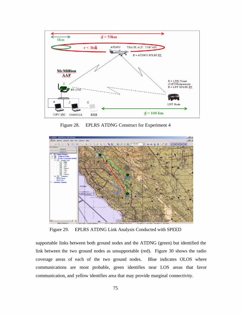
75
Figure 28. EPLRS ATDNG Construct for Experiment 4
Figure 29. EPLRS ATDNG Link Analysis Conducted with SPEED
supportable links between both ground nodes and the ATDNG (green) but identified the
link between the two ground nodes as unsupportable (red). Figure 30 shows the radio
coverage areas of each of the two ground nodes. Blue indicates OLOS where
communications are most probable, green identifies near LOS areas that favor
communication, and yellow identifies area that may provide marginal connectivity.

76
Figure 30. EPLRS RCA Analysis for LRV and TOC Conducted with SPEED
The final EPLRS RCA illustrates the advantage of using an ACN to provide OTH
connectivity between ground nodes. Figure 31 shows the radio coverage of the ATDNG
evaluated to a distance of 80km and underscores the potential for aircraft to relay data for
OMEs. The positions of the three nodes are identical to the previous RCAs depicted, but
the map view has been turned off to show ground contour rendered from digital terrain
elevation data. As seen in this analysis, both the TOC and the LRV are within OLOS
(blue) of the ATDNG.
c. Network Topology
The network topology for this experiment was consistent with the EPLRS
CSMAs used in previous experiments supporting this research but was expanded to
include connectivity to a premise router at the TOC (simulating access to the DII) and the
meshed network segment on the 98.0 network.

77
Figure 31. EPLRS RCA Analysis from ATDNG Conducted with SPEED
Figure 32. EPLRS Network Topology Supporting Experiment 4
5. Execution

78
The EPLRS RS supporting the LRV node (using a Chevy Trailblazer as a
surrogate) had been operated in parallel with 802.16 and 802.11 wireless networking
devices previous to this experiment. Originally installed in the back of the LRV with the
terminal equipment providing the mesh bridge, as depicted in Figure 33, the EPLRS RS
was relocated to the roof of the vehicle (Figure 34) to provide unobstructed LOS for the
man-packed antennas mounted to the face of the RT. 14 The meshed bridge was
provided by a C2PC laptop (depicted) interfaced to the OLSR mesh with an 802.11 NIC
and backhauled to the TOC via an 802.16 link.
Figure 33. LRV Communications Package for Mesh Bridging
14 Vehicular EPLRS antennas, which feature much better gain than the man-pack antennas, could not
be obtained for this research.

79
Figure 34. EPLRS RT Relocated Mounting for ATDNG Experimentation
For the experiment, the mesh bridge was removed from the LRV and
reestablished in the vicinity of the TOC (still wirelessly connected using the 802.16 link).
The meshed client segment used the bridge as their C2PC gateway and was tied to the
TOC by a C2PC gateway-to-gateway connection. The LRV, through the EPLRS link,
was also connected to the TOC’s C2PC gateway.
Network monitoring using Solarwinds was conducted from both the LRV and the
TOC for the duration of the experiment to evaluate network performance. As a backup to
the C2PC application, which had evidenced an apparent timing issue that prevented real-
time database synchronization, the SA Agent software was also installed on one of the
LRV’s client workstations and was used to track the progress of the LRV for the
experiment. The ENM was initially used to set timing on the EPLRS network and then
disconnected. Figure 35 shows the association of both of the ground nodes about forty-
five minutes prior to the start of the experiment. Note that RSID for the ATDNG, which
prior to 25 May had not used its EPLRS RS for several days, is reported as not being
associated and has no radio report timestamp in the ENM software.

80
Figure 35. EPLRS ENM Showing Nodal Association prior to ATDNG Availability
Execution of the experiment went smoothly and was successful in demonstrating
autonomous association. After ten days of sitting idle, the EPLRS RS on the ACN
quickly associated with the ground portion of the network, once it was airborne. Figure
36 shows the Solarwinds view of critical network nodes as monitored from the LRV
during the experiment.
Figure 36. Solarwinds Nodal Network Monitoring during Experiment 4

81
The LRV proceeded on its planned course and was monitored by the SA Agent
software. C2PC maintained its connection to the gateway throughout the experiment, but
due to the gateway synchronization issue (which after being troubleshot at the TOC was
determined to be a timing issue vice a product of either the meshed network or EPLRS
segment), it was unable to provide situation awareness data in real time. Figure 37 shows
the view provided by the SA Agent software to include network node statistics for the
LRV (before beginning OTM operations) as monitored from the TOC.
Figure 37. SA Agent Depicting LRV’s Nodal Network Status at < 1Km
Once OTM and OTH, response times between the TOC and the LRV remained
consistent with the laboratory experiments. Figure 38 depicts the LRV OTH at about
10km from the TOC while being relayed through the ATDNG. The throughput identifies
actual data being exchanged between the EPLRS connected hosts vice total BW capacity
of the node.

82
Figure 38. SA Agent Depicting LRV’s Nodal Network Status with ATDNG at 10Km
As expected, the LRV maintained data connectivity to the TOC by relaying
through the ATDNG for almost two hours after it departed Camp Roberts. The LRV
continued up Highway 101 as planned at the posted speed of 70mph and ended the test a
few miles North of King City (over 80 linear km from the TOC) due to rapidly
deteriorating data connectivity. Using Microsoft NetMeeting, an active chat between the
LRV and the TOC was maintained for the duration of the experiment. Using
NetMeeting’s file transfer utility, multiple files were exchanged between the sites to
measure throughput performance. Figure 39 provides a screen capture of the TOC’s
view of the LRV immediately prior to concluding this experiment.
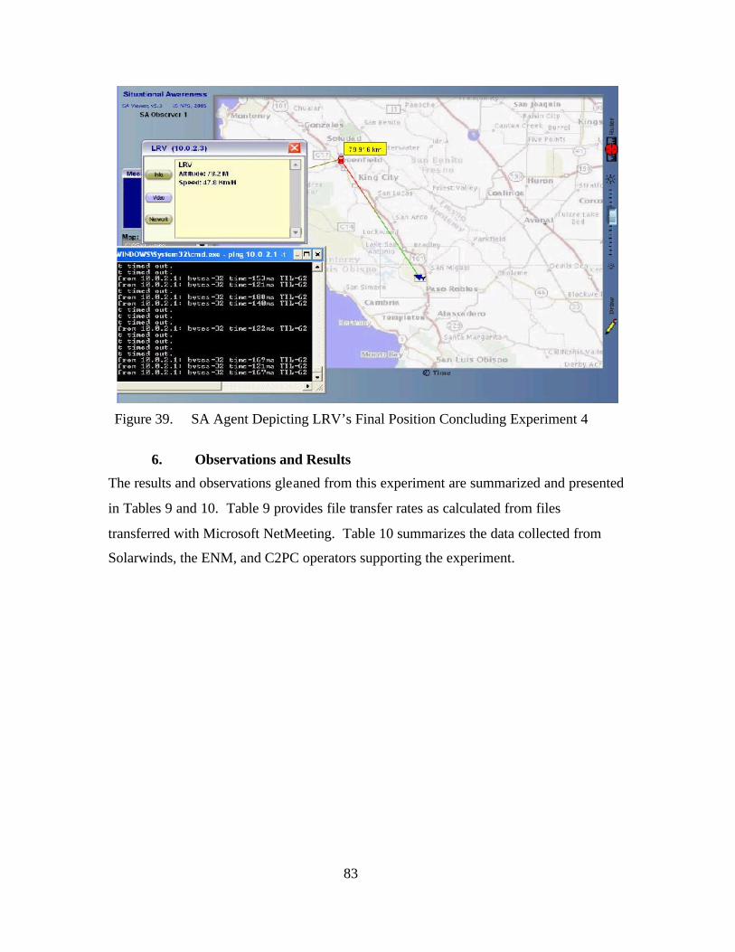
83
Figure 39. SA Agent Depicting LRV’s Final Position Concluding Experiment 4
6. Observations and Results
The results and observations gleaned from this experiment are summarized and presented
in Tables 9 and 10. Table 9 provides file transfer rates as calculated from files
transferred with Microsoft NetMeeting. Table 10 summarizes the data collected from
Solarwinds, the ENM, and C2PC operators supporting the experiment.

84
Table 9. Observed EPLRS Data Transfer Rates
Table 10. Summarized Observations Collected during Experiment 4

85
VII. CONCLUSIONS AND FUTURE RESEARCH RECOMMENDATIONS
A. CONCLUSIONS
EPLRS can successfully bridge between premise wired infrastructure and
commercial wireless networking segments without affecting the basic functional
performance of C2PC. Additionally, it was demonstrated that C2PC can operate on a
meshed wireless networking segment.
In evaluating the current functional capabilities commercially available in the
IEEE 802.11 and IEEE 802.16 standard, it was determined that neither of these wireless
networking solutions could be used effectively through an ACN. However, EPLRS is a
viable solution for extending tactical data connectivity to operational maneuver units
using an ATDNG architecture. Although throughput is modest when compared with that
of IEEE’s 802.11 and 802.16 standards, the exceptional range, flexibility, and autonomy
that can be achieved with an EPLRS CSMA through and ACN warrants additional
evaluation. Expanding the Marine Corps’ application of EPLRS to include its tactical air
assets, or by leveraging available network capacity already resident within USAF’s
SADL application can better accommodate the OTM and OTH data connectivity
requirements dictated by STOM and OMFTS.
B. FUTURE RESEARCH RECOMMENDATIONS
1. EPLRS MSG Networks from ATDNGs
An EPLRS CSMA network was used for this thesis because it offered the greatest
autonomy once configured. Although it would present additional coordination issues for
implementation, to better address QoS issues, an EPLRS MSG network should be
evaluated for potential ATDNG use.
2. ATDNG: Joint Force Arial Coverage within the JOA
This thesis suggests that ATDNG could be used as an opportunistic back-up to
existing OTH tactical data solutions. An assessment of the air-coverage within a JAO
that models the extent of air coverage available in a real-world deployment should be

86
conducted to determine the military potential for fitting all military aircraft with
autonomous data networking relays.
3. C2PC Performance in Meshed vs. Wireless Segments
C2PC’s performance assessment was conducted qualitatively in this thesis. A
quantitative analysis of C2PC performance between wired, wireless, and meshed wireless
network segments would provide insight on the potential impact using different mediums
and protocols.
4. SPEED Analysis of 802.16 COTS Radio Coverage Areas
SPEED was used to profile communication links that supported this thesis
research and returned very accurate results. For comparison, some effort was made to
adapt SPEED’s database to include 802.16 COTS equipment and to model OFDM
coverage areas. Initial results indicate that SPEED could be configured to model radio
coverage areas accurately for both 802.11 and 802.16 COTS equipment.

87
LIST OF REFERENCES
1. Raytheon Technical Workbook EPLRS System Technical Description
2. Raytheon’s EPLRS Flood Relay Presentation (PPT)
3. Naval Doctrinal Publication 6 (NDP 6)
4. Network Centric Warfare: Developing and Leveraging Information Superiority. Dave Alberts (et al), OSD/ASD(C3I), CCRP
http://www.defenselink.mil/nii/NCW/ncw_0801.pdf 2nd ed.
5. MCSC PMM122 CONDOR Website.
6. Department of the Navy. Ship to Objective Maneuver. Marine Corps Combat Development Command, VA, July 1997.
7. Joint Vision 2020
8. Strategic Environment and Implications [Concepts]
9. USJFCOM Website, Glossary of Terms
10. MARCORSYSCOM PMM122 Website http://www.marcorsyscom.usmc.mil/sites/pmcomm/index.asp, Last Accessed July 2005
11. Global Security.org: Leased Commercial Space Systems http://www.globalsecurity.org/space/systems/leased.htm
12. EPLRS Master Program Schedule, Raytheon Network Centric Systems
ppt brief dtd 8 Jan 2003, and 21 April 2005.
13. Intel White Paper: Understanding WiFi and WiMax Metro Access Solutions
14. Wikopedia, http://en.wikipedia.org/wiki/WiMAX accessed July 2005.
15. IEFT MANET Working Group Briefing on TBRPF, available online at http://tbrpf.erg.sri.com/docs/tbrpf-manet-mar02.ppt accessed June 2005
16. http://www.networksorcery.com/enp/protocol/tbrpf.htm accessed July 2005
17. Bach, Eric J. and Fickle, Mark G. An Analysis of the Feasibility and Applicability of IEEE 802.X Wireless Mesh Networks Within the Global Information Grid. Master’s thesis, Naval Postgraduate School, September 2004.

88
18. Clausen, T and P. Jacket, “Optimized Link State Routing,” RFC 3626, October 2003. Available online at http://hipercom.inria.fr/olsr/rfc3626.txt Last accessed July 2005.

89
BIBLIOGRAPHY
Alberts, David et al, Network Centric Warfare: Developing and Leveraging Information Superiority, CCRP Publication Series, February 2000
Bach, Eric J. and Fickle, Mark G. “An Analysis of the Feasibility and Applicability of
IEEE 802.X Wireless Mesh Networks Within the Global Information Grid.” Master’s thesis, Naval Postgraduate School, September 2004.
Chan, Hsiung Wei Roy. “Performance Analysis of IEEE 803.11a Signals Under
Different Operational Environments.” Master’s thesis, Naval Postgraduate School, September 2004.
Clausen, T. and P. Jacket, “Optimized Link State Routing.” RFC 3626, October 2003.
Cohen, Beth and Deutsch, Debbie. IEEE 802.16: The Future in Last Mile Wireless Connectivity. IEEE, 2003.
Communications System Division, Marine Corps Systems Command, Headquarters,
USMC, brief. Transforming Marine Corps C4I. Aug 2003. Davies, D. and C. Davies. “Scale the Hurdles Associated with Mesh Networks.”
CommDesign.com, Apr 2005. Available from http://www.commdesign.com/showArticle.jhtml?articleID=160911814 last accessed July 2005.
Gerla, Mario, Xiaoyan Hong. “Exploiting Mobility in Large Scale Ad Hoc Wireless
Networks.” IEEE Computer Communication Workshop (CCW’03), Dana Point, CA, October 2003.
Guice, Robert J. and Munoz, Ramon J. “IEEE 802.16 Commercial Off The Shelf
(COTS) Technologies as a Compliment to Ship to Objective Maneuver (STOM) Communications.” Master’s thesis, Naval Postgraduate School, September 2004.
Headquarters Marine Corps, Program and Resources Department. Concepts and
Programs 2005. Washington, D.C., June 2005. Also available online at http://www.hqmc.usmc.mil
Hunt, Col Carl, et al, “Net Force Maneuver.” United States Military Academy, West
Point, NY. June 2005. Motorola Mesh Networks home page Available at
http://www.motorola.com/businessandgovernment/northamerica/en=us/public/functions/browsesolution/browsesesolution.aspx?navigationpath=id_804i/id_2523i
Last Accessed July 2005.

90
Milicic, Gregary J. “An Analysis of Tactical Mesh Networking Hardware Requirements for Airborne Mobile Nodes.” Master’s thesis, Naval Postgraduate School, March 2005.
OrderOne Networks. An Abbreviated Technical Discussion of the OrderOne Networks
Protocol Version 1.1. White Paper, OrderOne Networks. 2005. Redline Communications home page. Available from http://redlinecommunications.com Last Accessed July 2005. Redline Communications White Paper. Advantages of Broadband Fixed Wireless
Systems over 802.11 LANs. Available from http://www.redlinecommunications.com/products/an50/an50e.pdf Last Accessed July 2005.
Sweeny, Daniel, WiMax Operator’s Manual: Building 802.16 Wireless Networks, Apress
Publishing, May 2004.

91
INITIAL DISTRIBUTION LIST
1. Defense Technical Information Center Ft. Belvoir, Virginia
2. Dudley Knox Library Naval Postgraduate School Monterey, California
3. Marine Corps Representative Naval Postgraduate School Monterey, California
4. Chairman, Information Sciences Department
Naval Postgraduate School Monterey, California
5. Marine Corps Systems Command (Attn: Program Manager Communications (PMM122), MAGTF C4ISR (PG12))
Quantico, Virginia
6. Space and Naval Warfare Systems Command – SSC San Diego (Attn: Mr. Bill Schemensky & Ms. Kelly Sobon) San Diego, California
7. Director, Marine Corps Research Center MCCDC. Code C40RC
Quantico, Virginia
8. Office of Naval Research Arlington, Virginia
9. Marine Corps Warfighting Laboratory (Attn: C4) Quantico, Virginia
10. Headquarters Marine Corps (C4) Arlington, Virginia
11. Marine Corps Tactical Systems Support Activity (Attn: Operations Officer, and EPLRS Program Officer)
Camp Pendleton, California

92
THIS PAGE INTENTIONALLY LEFT BLANK