Embed Size (px)
Citation preview

Manual No. 0-2784August 23, 1999
Operating Manual
A-02464
Air Plasma CuttingPower Supply (CE)
WARNING
WARNING
Read and understand this entire Operating Manual and youremployer’s safety practices before installing, operating, orservicing the equipment.
While the information contained in this Operating Manualrepresents our best judgement, Thermal Dynamics Corporationassumes no liability for its use.
Pak Master® 100XL PLUS Air Plasma Cutting Power Supply(CE)Operating Manual Number 0-2784
Published by:Thermal Dynamics CorporationIndustrial Park No. 2West Lebanon, New Hampshire, USA 03784(603) 298-5711
Copyright 1999 byThermal Dynamics Corporation
All rights reserved.
Reproduction of this work, in whole or in part, without writtenpermission of the publisher is prohibited.
The publisher does not assume and hereby disclaims any liabilityto any party for any loss or damage caused by any error oromission in the Pak Master® 100XL PLUS Air Plasma CuttingPower Supply (CE) Operating Manual, 0-2784,whether sucherror results from negligence, accident, or any other cause.
Printed in the United States of America
August 1999

Purchase Date
Power Supply
Torch
Record Serial Numbers For Warranty Purposes


TABLE OF CONTENTS
SECTION 1:GENERAL INFORMATION .................................................................................................. 1
1.01 Notes, Cautions and Warnings ...................................................................... 11.02 Important Safety Precautions ........................................................................ 11.03 Publications ................................................................................................... 21.04 Note, Attention et Avertissement ................................................................... 31.05 Precautions De Securite Importantes ............................................................ 31.06 Documents De Reference ............................................................................. 51.07 Declaration of Conformity .............................................................................. 71.08 Statement of Warranty ................................................................................... 8
SECTION 2:INTRODUCTION ................................................................................................................. 9
2.01 Scope of Manual ............................................................................................ 92.02 General Description of System ...................................................................... 92.03 Specifications/Design Features ..................................................................... 92.04 Power Supply Options and Accessories ...................................................... 10
SECTION 3:INSTALLATION PROCEDURES ........................................................................................ 11
3.01 Introduction .................................................................................................. 113.02 Site Selection............................................................................................... 113.03 Unpacking ................................................................................................... 113.04 Lifting Options.............................................................................................. 113.05 Input Power Cable Connections ................................................................... 123.06 Gas Connections ......................................................................................... 123.07 Connecting Torch Leads .............................................................................. 143.08 Work Cable And Ground Connections ......................................................... 153.09 Tip Saver/Drag Cut Sensing Circuit ............................................................. 16
SECTION 4:OPERATION ...................................................................................................................... 17
4.01 Introduction .................................................................................................. 174.02 Functional Overview .................................................................................... 174.03 Operating Controls ...................................................................................... 174.04 Sequence Of Operation ............................................................................... 194.05 Preparations for Operating ........................................................................... 204.06 Cut Quality ................................................................................................... 21
SECTION 5:CUSTOMER/OPERATOR SERVICE .................................................................................. 23
5.01 Introduction .................................................................................................. 235.02 General Maintenance .................................................................................. 235.03 Common Operating Problems ..................................................................... 245.04 Troubleshooting Guide ................................................................................. 255.05 Power Supply Parts Replacement ............................................................... 27

TABLE OF CONTENTS (continued)
SECTION 6:PARTS LISTS..................................................................................................................... 29
6.01 Introduction .................................................................................................. 296.02 Ordering Information .................................................................................... 296.03 Complete Power Supply Replacement ......................................................... 306.04 Replacement Parts ...................................................................................... 306.05 Options and Accessories ............................................................................. 30
APPENDIX I: INPUT WIRING REQUIREMENTS ...................................................................... 31
APPENDIX II: SEQUENCE OF OPERATION (BLOCK DIAGRAM) ........................................... 32
APPENDIX III: SYSTEM SCHEMATIC....................................................................................... 34

Date: 6/22/99 1 GENERAL INFORMATION
SECTION 1:GENERAL INFORMATION
1.01 Notes, Cautions and Warnings
Throughout this manual, notes, cautions, and warningsare used to highlight important information. These high-lights are categorized as follows:
NOTE
An operation, procedure, or background informa-tion which requires additional emphasis or is help-ful in efficient operation of the system.
CAUTION
A procedure which, if not properly followed, maycause damage to the equipment.
WARNING
A procedure which, if not properly followed, maycause injury to the operator or others in the oper-ating area.
1.02 Important Safety Precautions
WARNINGS
OPERATION AND MAINTENANCE OFPLASMA ARC EQUIPMENT CAN BE DAN-GEROUS AND HAZARDOUS TO YOURHEALTH.
Plasma arc cutting produces intense electric andmagnetic emissions that may interfere with theproper function of cardiac pacemakers, hearingaids, or other electronic health equipment. Per-sons who work near plasma arc cutting applica-tions should consult their medical health profes-sional and the manufacturer of the healthequipment to determine whether a hazard exists.
To prevent possible injury, read, understand andfollow all warnings, safety precautions and in-structions before using the equipment. Call 1-603-298-5711 or your local distributor if you have anyquestions.
GASES AND FUMES
Gases and fumes produced during the plasma cuttingprocess can be dangerous and hazardous to your health.
• Keep all fumes and gases from the breathing area.Keep your head out of the welding fume plume.
• Use an air-supplied respirator if ventilation is notadequate to remove all fumes and gases.
• The kinds of fumes and gases from the plasma arcdepend on the kind of metal being used, coatingson the metal, and the different processes. You mustbe very careful when cutting or welding any met-als which may contain one or more of the follow-ing:
Antimony Chromium MercuryArsenic Cobalt NickelBarium Copper SeleniumBeryllium Lead SilverCadmium Manganese Vanadium
• Always read the Material Safety Data Sheets (MSDS)that should be supplied with the material you areusing. These MSDSs will give you the informationregarding the kind and amount of fumes and gasesthat may be dangerous to your health.
• For information on how to test for fumes and gasesin your workplace, refer to item 1 in Subsection1.03, Publications in this manual.
• Use special equipment, such as water or down draftcutting tables, to capture fumes and gases.
• Do not use the plasma torch in an area where com-bustible or explosive gases or materials are located.
• Phosgene, a toxic gas, is generated from the vaporsof chlorinated solvents and cleansers. Remove allsources of these vapors.
ELECTRIC SHOCK
Electric Shock can injure or kill. The plasma arc processuses and produces high voltage electrical energy. Thiselectric energy can cause severe or fatal shock to the op-erator or others in the workplace.
• Never touch any parts that are electrically “live” or“hot.”
• Wear dry gloves and clothing. Insulate yourself fromthe work piece or other parts of the welding cir-cuit.
• Repair or replace all worn or damaged parts.
• Extra care must be taken when the workplace ismoist or damp.
GENERAL INFORMATION 2 Date 6/22/99
• Install and maintain equipment according to NECcode, refer to item 9 in Subsection 1.03, Publica-tions.
• Disconnect power source before performing any ser-vice or repairs.
• Read and follow all the instructions in the Operat-ing Manual.
FIRE AND EXPLOSION
Fire and explosion can be caused by hot slag, sparks, orthe plasma arc.
• Be sure there is no combustible or flammable mate-rial in the workplace. Any material that cannot beremoved must be protected.
• Ventilate all flammable or explosive vapors fromthe workplace.
• Do not cut or weld on containers that may have heldcombustibles.
• Provide a fire watch when working in an area wherefire hazards may exist.
• Hydrogen gas may be formed and trapped underaluminum workpieces when they are cut under-water or while using a water table. DO NOT cutaluminum alloys underwater or on a water tableunless the hydrogen gas can be eliminated or dis-sipated. Trapped hydrogen gas that is ignited willcause an explosion.
NOISE
Noise can cause permanent hearing loss. Plasma arc pro-cesses can cause noise levels to exceed safe limits. Youmust protect your ears from loud noise to prevent per-manent loss of hearing.
• To protect your hearing from loud noise, wear pro-tective ear plugs and/or ear muffs. Protect othersin the workplace.
• Noise levels should be measured to be sure the deci-bels (sound) do not exceed safe levels.
• For information on how to test for noise, see item 1in Subsection 1.03, Publications, in this manual.
PLASMA ARC RAYS
Plasma Arc Rays can injure your eyes and burn your skin.The plasma arc process produces very bright ultra violetand infra red light. These arc rays will damage youreyes and burn your skin if you are not properly protected.
• To protect your eyes, always wear a welding hel-met or shield. Also always wear safety glasses withside shields, goggles or other protective eye wear.
• Wear welding gloves and suitable clothing to pro-tect your skin from the arc rays and sparks.
• Keep helmet and safety glasses in good condition.Replace lenses when cracked, chipped or dirty.
• Protect others in the work area from the arc rays.Use protective booths, screens or shields.
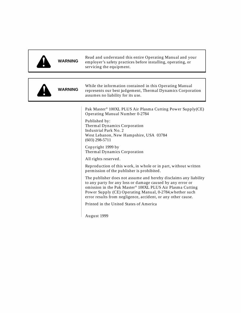
• Use the shade of lens as suggested in the followingper ANSI/ASC Z49.1:
Minimum Protective SuggestedArc Current Shade No. Shade No.
Less Than 300* 8 9
300 - 400* 9 12
400 - 800* 10 14
* These values apply where the actual arc is clearlyseen. Experience has shown that lighter filtersmay be used when the arc is hidden by the work-piece.
1.03 Publications
Refer to the following standards or their latest revisionsfor more information:
1. OSHA, SAFETY AND HEALTH STANDARDS,29CFR 1910, obtainable from the Superintendent ofDocuments, U.S. Government Printing Office, Wash-ington, D.C. 20402
2. ANSI Standard Z49.1, SAFETY IN WELDING ANDCUTTING, obtainable from the American WeldingSociety, 550 N.W. LeJeune Rd, Miami, FL 33126
3. NIOSH, SAFETY AND HEALTH IN ARC WELD-ING AND GAS WELDING AND CUTTING, obtain-able from the Superintendent of Documents, U.S.Government Printing Office, Washington, D.C. 20402
4. ANSI Standard Z87.1, SAFE PRACTICES FOR OC-CUPATION AND EDUCATIONAL EYE AND FACEPROTECTION, obtainable from American NationalStandards Institute, 1430 Broadway, New York, NY10018
5. ANSI Standard Z41.1, STANDARD FOR MEN’SSAFETY-TOE FOOTWEAR, obtainable from theAmerican National Standards Institute, 1430 Broad-way, New York, NY 10018
6. ANSI Standard Z49.2, FIRE PREVENTION IN THEUSE OF CUTTING AND WELDING PROCESSES,obtainable from American National Standards Insti-tute, 1430 Broadway, New York, NY 10018
7. AWS Standard A6.0, WELDING AND CUTTINGCONTAINERS WHICH HAVE HELD COMBUS-TIBLES, obtainable from American Welding Society,550 N.W. LeJeune Rd, Miami, FL 33126

Date: 6/22/99 3 GENERAL INFORMATION
8. NFPA Standard 51, OXYGEN-FUEL GAS SYSTEMSFOR WELDING, CUTTING AND ALLIED PRO-CESSES, obtainable from the National Fire ProtectionAssociation, Batterymarch Park, Quincy, MA 02269
9. NFPA Standard 70, NATIONAL ELECTRICAL CODE,obtainable from the National Fire Protection Asso-ciation, Batterymarch Park, Quincy, MA 02269
10. NFPA Standard 51B, CUTTING AND WELDINGPROCESSES, obtainable from the National Fire Pro-tection Association, Batterymarch Park, Quincy, MA02269
11. CGA Pamphlet P-1, SAFE HANDLING OF COM-PRESSED GASES IN CYLINDERS, obtainable fromthe Compressed Gas Association, 1235 JeffersonDavis Highway, Suite 501, Arlington, VA 22202
12. CSA Standard W117.2, CODE FOR SAFETY INWELDING AND CUTTING, obtainable from the Ca-nadian Standards Association, Standards Sales, 178Rexdale Boulevard, Rexdale, Ontario, Canada M9W1R3
13. NWSA booklet, WELDING SAFETY BIBLIOGRA-PHY obtainable from the National Welding SupplyAssociation, 1900 Arch Street, Philadelphia, PA 19103
14. American Welding Society Standard AWSF4.1, REC-OMMENDED SAFE PRACTICES FOR THE PREPA-RATION FOR WELDING AND CUTTING OF CON-TAINERS AND PIPING THAT HAVE HELDHAZARDOUS SUBSTANCES, obtainable from theAmerican Welding Society, 550 N.W. LeJeune Rd,Miami, FL 33126
15. ANSI Standard Z88.2, PRACTICE FOR RESPIRA-TORY PROTECTION, obtainable from AmericanNational Standards Institute, 1430 Broadway, NewYork, NY 10018
1.04 Note, Attention etAvertissement
Dans ce manuel, les mots “note,” “attention,” et“avertissement” sont utilisés pour mettre en relief desinformations à caractère important. Ces mises en reliefsont classifiées comme suit :
NOTE
Toute opération, procédure ou renseignementgénéral sur lequel il importe d’insister davantageou qui contribue à l’efficacité de fonctionnementdu système.
ATTENTION
Toute procédure pouvant résulterl’endommagement du matériel en cas de non-respect de la procédure en question.
AVERTISSEMENT
Toute procédure pouvant provoquer des blessuresde l’opérateur ou des autres personnes se trouvantdans la zone de travail en cas de non-respect de laprocédure en question.
1.05 Precautions De SecuriteImportantes
AVERTISSEMENTS
L’OPÉRATION ET LA MAINTENANCE DUMATÉRIEL DE SOUDAGE À L’ARC AU JETDE PLASMA PEUVENT PRÉSENTER DESRISQUES ET DES DANGERS DE SANTÉ.
Coupant à l’arc au jet de plasma produit de l’énergieélectrique haute tension et des émissionsmagnétique qui peuvent interférer la fonctionpropre d’un “pacemaker” cardiaque, les appareilsauditif, ou autre matériel de santé electronique.Ceux qui travail près d’une application à l’arc aujet de plasma devrait consulter leur membreprofessionel de médication et le manufacturier dematériel de santé pour déterminer s’il existe desrisques de santé.
Il faut communiquer aux opérateurs et au person-nel TOUS les dangers possibles. Afin d’éviter lesblessures possibles, lisez, comprenez et suivez tousles avertissements, toutes les précautions de sécuritéet toutes les consignes avant d’utiliser le matériel.Composez le + 603-298-5711 ou votre distributeurlocal si vous avez des questions.
FUMÉE et GAZ
La fumée et les gaz produits par le procédé de jet deplasma peuvent présenter des risques et des dangers desanté.
• Eloignez toute fumée et gaz de votre zone de respi-ration. Gardez votre tête hors de la plume de fuméeprovenant du chalumeau.
• Utilisez un appareil respiratoire à alimentation enair si l’aération fournie ne permet pas d’éliminer lafumée et les gaz.

GENERAL INFORMATION 4 Date 6/22/99
• Les sortes de gaz et de fumée provenant de l’arc deplasma dépendent du genre de métal utilisé, desrevêtements se trouvant sur le métal et des différentsprocédés. Vous devez prendre soin lorsque vouscoupez ou soudez tout métal pouvant contenir unou plusieurs des éléments suivants:
antimoine cadmium mercureargent chrome nickelarsenic cobalt plombbaryum cuivre séléniumbéryllium manganèse vanadium
• Lisez toujours les fiches de données sur la sécuritédes matières (sigle américain “MSDS”); celles-cidevraient être fournies avec le matériel que vousutilisez. Les MSDS contiennent des renseignementsquant à la quantité et la nature de la fumée et desgaz pouvant poser des dangers de santé.
• Pour des informations sur la manière de tester lafumée et les gaz de votre lieu de travail, consultezl’article 1 et les documents cités à la page 5.
• Utilisez un équipement spécial tel que des tables decoupe à débit d’eau ou à courant descendant pourcapter la fumée et les gaz.
• N’utilisez pas le chalumeau au jet de plasma dansune zone où se trouvent des matières ou des gazcombustibles ou explosifs.
• Le phosgène, un gaz toxique, est généré par la fuméeprovenant des solvants et des produits de nettoyagechlorés. Eliminez toute source de telle fumée.
CHOC ELECTRIQUE
Les chocs électriques peuvent blesser ou même tuer. Leprocédé au jet de plasma requiert et produit de l’énergieélectrique haute tension. Cette énergie électrique peutproduire des chocs graves, voire mortels, pour l’opérateuret les autres personnes sur le lieu de travail.
• Ne touchez jamais une pièce “sous tension” ou“vive”; portez des gants et des vêtements secs.Isolez-vous de la pièce de travail ou des autres par-ties du circuit de soudage.
• Réparez ou remplacez toute pièce usée ouendommagée.
• Prenez des soins particuliers lorsque la zone de tra-vail est humide ou moite.
• Montez et maintenez le matériel conformément auCode électrique national des Etats-Unis. (Voir lapage 5, article 9.)
• Débranchez l’alimentation électrique avant tout tra-vail d’entretien ou de réparation.
• Lisez et respectez toutes les consignes du Manuelde consignes.
INCENDIE ET EXPLOSION
Les incendies et les explosions peuvent résulter des scorieschaudes, des étincelles ou de l’arc de plasma. Le procédéà l’arc de plasma produit du métal, des étincelles, desscories chaudes pouvant mettre le feu aux matières com-bustibles ou provoquer l’explosion de fuméesinflammables.
• Soyez certain qu’aucune matière combustible ou in-flammable ne se trouve sur le lieu de travail.Protégez toute telle matière qu’il est impossible deretirer de la zone de travail.
• Procurez une bonne aération de toutes les fuméesinflammables ou explosives.
• Ne coupez pas et ne soudez pas les conteneurs ayantpu renfermer des matières combustibles.
• Prévoyez une veille d’incendie lors de tout travaildans une zone présentant des dangers d’incendie.
• Le gas hydrogène peut se former ou s’accumulersous les pièces de travail en aluminium lorsqu’ellessont coupées sous l’eau ou sur une table d’eau. NEPAS couper les alliages en aluminium sous l’eau ousur une table d’eau à moins que le gas hydrogènepeut s’échapper ou se dissiper. Le gas hydrogèneaccumulé explosera si enflammé.
RAYONS D’ARC DE PLASMA
Les rayons provenant de l’arc de plasma peuvent blesservos yeux et brûler votre peau. Le procédé à l’arc de plasmaproduit une lumière infra-rouge et des rayons ultra-vio-lets très forts. Ces rayons d’arc nuiront à vos yeux etbrûleront votre peau si vous ne vous protégez pascorrectement.
• Pour protéger vos yeux, portez toujours un casqueou un écran de soudeur. Portez toujours des lunettesde sécurité munies de parois latérales ou des lu-nettes de protection ou une autre sorte de protec-tion oculaire.
• Portez des gants de soudeur et un vêtementprotecteur approprié pour protéger votre peaucontre les étincelles et les rayons de l’arc.
• Maintenez votre casque et vos lunettes de protec-tion en bon état. Remplacez toute lentille sale oucomportant fissure ou rognure.
• Protégez les autres personnes se trouvant sur la zonede travail contre les rayons de l’arc en fournissantdes cabines ou des écrans de protection.

Date: 6/22/99 5 GENERAL INFORMATION
• Utilisez la nuance de lentille qui est suggèrée dansle recommendation qui suivent ANSI/ASC Z49.1:
Nuance Minimum Nuance SuggeréeCourant Arc Protective Numéro Numéro
Moins de 300* 8 9
300 - 400* 9 12
400 - 800* 10 14
* Ces valeurs s’appliquent ou l’arc actuel est observéclairement. L’experience a démontrer que les filtresmoins foncés peuvent être utilisés quand l’arc estcaché par moiceau de travail.
BRUIT
Le bruit peut provoquer une perte permanente de l’ouïe.Les procédés de soudage à l’arc de plasma peuventprovoquer des niveaux sonores supérieurs aux limitesnormalement acceptables. Vous dú4ez vous protéger lesoreilles contre les bruits forts afin d’éviter une pertepermanente de l’ouïe.
• Pour protéger votre ouïe contre les bruits forts, portezdes tampons protecteurs et/ou des protectionsauriculaires. Protégez également les autrespersonnes se trouvant sur le lieu de travail.
• Il faut mesurer les niveaux sonores afin d’assurerque les décibels (le bruit) ne dépassent pas lesniveaux sûrs.
• Pour des renseignements sur la manière de tester lebruit, consultez l’article 1, page 5.
1.06 Documents De Reference
Consultez les normes suivantes ou les révisions les plusrécentes ayant été faites à celles-ci pour de plus amplesrenseignements :
1. OSHA, NORMES DE SÉCURITÉ DU TRAVAIL ETDE PROTECTION DE LA SANTÉ, 29CFR 1910,disponible auprès du Superintendent of Docu-ments, U.S. Government Printing Office, Washing-ton, D.C. 20402
2. Norme ANSI Z49.1, LA SÉCURITÉ DESOPÉRATIONS DE COUPE ET DE SOUDAGE,disponible auprès de la Société Américaine deSoudage (American Welding Society), 550 N.W.LeJeune Rd., Miami, FL 33126
3. NIOSH, LA SÉCURITÉ ET LA SANTÉ LORS DESOPÉRATIONS DE COUPE ET DE SOUDAGE ÀL’ARC ET AU GAZ, disponible auprès du Superin-tendent of Documents, U.S. Government PrintingOffice, Washington, D.C. 20402
4. Norme ANSI Z87.1, PRATIQUES SURES POUR LAPROTECTION DES YEUX ET DU VISAGE AUTRAVAIL ET DANS LES ECOLES, disponible del’Institut Américain des Normes Nationales (Ameri-can National Standards Institute), 1430 Broadway,New York, NY 10018
5. Norme ANSI Z41.1, NORMES POUR LESCHAUSSURES PROTECTRICES, disponible auprèsde l’American National Standards Institute, 1430Broadway, New York, NY 10018
6. Norme ANSI Z49.2, PRÉVENTION DESINCENDIES LORS DE L’EMPLOI DE PROCÉDÉSDE COUPE ET DE SOUDAGE, disponible auprèsde l’American National Standards Institute, 1430Broadway, New York, NY 10018
7. Norme A6.0 de l’Association Américaine duSoudage (AWS), LE SOUDAGE ET LA COUPE DECONTENEURS AYANT RENFERMÉ DESPRODUITS COMBUSTIBLES, disponible auprès dela American Welding Society, 550 N.W. LeJeune Rd.,Miami, FL 33126
8. Norme 51 de l’Association Américaine pour la Pro-tection contre les Incendies (NFPA), LES SYSTEMESÀ GAZ AVEC ALIMENTATION EN OXYGENEPOUR LE SOUDAGE, LA COUPE ET LESPROCÉDÉS ASSOCIÉS, disponible auprès de laNational Fire Protection Association, BatterymarchPark, Quincy, MA 02269
9. Norme 70 de la NFPA, CODE ELECTRIQUE NA-TIONAL, disponible auprès de la National Fire Pro-tection Association, Batterymarch Park, Quincy, MA02269
10. Norme 51B de la NFPA, LES PROCÉDÉS DECOUPE ET DE SOUDAGE, disponible auprès dela National Fire Protection Association,Batterymarch Park, Quincy, MA 02269
11. Brochure GCA P-1, LA MANIPULATION SANSRISQUE DES GAZ COMPRIMÉS EN CYLINDRES,disponible auprès de l’Association des GazComprimés (Compressed Gas Association), 1235Jefferson Davis Highway, Suite 501, Arlington, VA22202
12. Norme CSA W117.2, CODE DE SÉCURITÉ POURLE SOUDAGE ET LA COUPE, disponible auprèsde l’Association des Normes Canadiennes, Stan-dards Sales, 178 Rexdale Boulevard, Rexdale,Ontario, Canada, M9W 1R3
13. ivret NWSA, BIBLIOGRAPHIE SUR LA SÉCURITÉDU SOUDAGE, disponible auprès de l’AssociationNationale de Fournitures de Soudage (NationalWelding Supply Association), 1900 Arch Street,Philadelphia, PA 19103

GENERAL INFORMATION 6 Date 6/22/99
14. Norme AWSF4.1 de l’Association Américaine deSoudage, RECOMMANDATIONS DE PRA-TIQUES SURES POUR LA PRÉPARATION À LACOUPE ET AU SOUDAGE DE CONTENEURSET TUYAUX AYANT RENFERMÉ DESPRODUITS DANGEREUX , disponible auprès dela American Welding Society, 550 N.W. LeJeuneRd., Miami, FL 33126
15. Norme ANSI Z88.2, PRATIQUES DE PROTEC-TION RESPIRATOIRE, disponible auprès del’American National Standards Institute, 1430Broadway, New York, NY 10018

Date: 6/22/99 7 GENERAL INFORMATION
1.07 Declaration of ConformityManufacturer: Thermal Dynamics CorporationAddress: Industrial Park #2
West Lebanon, New Hampshire 03784USA
The equipment described in this manual conforms to all applicable aspects and regulations of the ‘Low Voltage Direc-tive’ (European Council Directive 73/23/EEC as amended by Council Directive 93/68/EEC) and to the Nationallegislation for the enforcement of this Directive.
The equipment described in this manual conforms to all applicable aspects and regulations of the "EMC Directive"(European Council Directive 89/336/EEC) and to the National legislation for the enforcement of this Directive.
Serial numbers are unique with each individual piece of equipment and details description, parts used to manufacturea unit and date of manufacture.
National Standard and Technical Specifications
The product is designed and manufactured to a number of standards and technical requirements among them are:
* CSA (Canadian Standards Association) standard C22.2 number 60 for Arc welding equipment.
* UL (Underwriters Laboratory) rating 94VO flammability testing for all printed-circuit boards used.
* CENELEC EN50199 EMC Product Standard for Arc Welding Equipment.
* ISO/IEC 60974-1 (BS 638-PT10) (EN 60 974-1) (EN50192) (EN50078) applicable to plasma cutting equipment and associ-ated accessories.
* Extensive product design verification is conducted at the manufacturing facility as part of the routine design andmanufacturing process. This is to ensure the product is safe, when used according to instructions in this manual andrelated industry standards, and performs as specified. Rigorous testing is incorporated into the manufacturingprocess to ensure the manufactured product meets or exceeds all design specifications.
Thermal Dynamics has been manufacturing products for more than 30 years, and will continue to achieve excellence in ourarea of manufacture.
Manufacturers responsible representative: Steve WardDirector of OperationsThermadyne UKChorley England

GENERAL INFORMATION 8 Date 6/22/99
1.08 Statement of Warranty
LIMITED WARRANTY: Thermal Dynamics® Corporation (hereinafter “Thermal”) warrants that its products will be free of defects inworkmanship or material. Should any failure to conform to this warranty appear within the time period applicable to the Thermalproducts as stated below, Thermal shall, upon notification thereof and substantiation that the product has been stored, installed, operated,and maintained in accordance with Thermal’s specifications, instructions, recommendations and recognized standard industry practice,and not subject to misuse, repair, neglect, alteration, or accident, correct such defects by suitable repair or replacement, at Thermal’s soleoption, of any components or parts of the product determined by Thermal to be defective.
THIS WARRANTY IS EXCLUSIVE AND IS IN LIEU OF ANY WARRANTY OF MERCHANTABILITY OR FITNESS FOR APARTICULAR PURPOSE.
LIMITATION OF LIABILITY: Thermal shall not under any circumstances be liable for special or consequential damages, such as, butnot limited to, damage or loss of purchased or replacement goods, or claims of customers of distributor (hereinafter “Purchaser”) forservice interruption. The remedies of the Purchaser set forth herein are exclusive and the liability of Thermal with respect to anycontract, or anything done in connection therewith such as the performance or breach thereof, or from the manufacture, sale, delivery,resale, or use of any goods covered by or furnished by Thermal whether arising out of contract, negligence, strict tort, or under anywarranty, or otherwise, shall not, except as expressly provided herein, exceed the price of the goods upon which such liability is based.
THIS WARRANTY BECOMES INVALID IF REPLACEMENT PARTS OR ACCESSORIES ARE USED WHICH MAY IMPAIR THESAFETY OR PERFORMANCE OF ANY THERMAL PRODUCT.
THIS WARRANTY IS INVALID IF THE PRODUCT IS SOLD BY NON-AUTHORIZED PERSONS.
The limited warranty periods for Thermal products shall be as follows (with the exception of XL Plus Series, CutMaster 80XL , Cougarand DRAG-GUN): A maximum of three (3) years from date of sale to an authorized distributor and a maximum of two (2) years fromdate of sale by such distributor to the Purchaser, and with the further limitations on such two (2) year period (see chart below).
The limited warranty period for XL Plus Series and CutMaster 80XL shall be as follows: A maximum of four (4) years from dateof sale to an authorized distributor and a maximum of three (3) years from date of sale by such distributor to the Purchaser, andwith the further limitations on such three (3) year period (see chart below).
The limited warranty period for Cougar and DRAG-GUN shall be as follows: A maximum of two (2) years from date of sale to anauthorized distributor and a maximum of one (1) year from date of sale by such distributor to the Purchaser, and with the furtherlimitations on such two (2) year period (see chart below).
Parts
XL Plus Series & Parts PartsPAK Units, Power Supplies CutMaster 80XL Cougar/Drag-Gun All Others Labor
Main Power Magnetics 3 Years 1 Year 2 Years 1 Year
Original Main Power Rectifier 3 Years 1 Year 2 Years 1 Year
Control PC Board 3 Years 1 Year 2 Years 1 Year
All Other Circuits And Components Including, 1 Year 1 Year 1 Year 1 YearBut Not Limited To, Starting Circuit,Contactors, Relays, Solenoids, Pumps,Power Switching Semi-Conductors
Consoles, Control Equipment, Heat 1 Year 1 Year 1 YearExchanges, And Accessory Equipment
Torch And Leads
Maximizer 300 Torch 1 Year 1 Year
All Other Torches 180 Days 180 Days 180 Days 180 Days
Repair/Replacement Parts 90 Days 90 Days 90 Days None
Warranty repairs or replacement claims under this limited warranty must be submitted by an authorized Thermal Dynamics® repairfacility within thirty (30) days of the repair. No transportation costs of any kind will be paid under this warranty. Transportationcharges to send products to an authorized warranty repair facility shall be the responsibility of the customer. All returned goods shallbe at the customer’s risk and expense. This warranty supersedes all previous Thermal warranties.
Effective May 6, 1999

Manual 0-2784 9 SECTION 2: INTRODUCTION
SECTION 2:INTRODUCTION
2.01 Scope of Manual
This manual contains descriptions, operating instructions,and basic maintenance procedures for the PAK Master®
100XL PLUS Air Plasma Cutting Power Supply (CE) only.Service of this equipment is restricted to Thermal Dynam-ics trained personnel; unqualified personnel are strictlycautioned against attempting repairs or adjustments notcovered in this manual, at the risk of voiding the War-ranty.
Read this manual thoroughly. A complete understand-ing of the characteristics and capabilities of this equip-ment will assure the dependable operation for which itwas designed.
2.02 General Description of System
The 100XL PLUS (CE) System includes a power supply,PCH/M-80 torch & leads, work cable & clamp, and in-put power cable.
The Power Supply provides 80 amp maximum outputand includes all control circuitry, electrical and gas in-puts and outputs, pilot circuitry, torch leads receptacle,input power cable, and a work cable with clamp.
NOTE
The power supply can be ordered in various con-figurations with various options factory installed.
A-02462
Torch and Leads
Work Cable and Clamp
XL PLUS Power Supply
Figure 2-1 Pak Master 100XL Plus (CE) System
The PCH/M-80 torch provides a maximum 1 inch (25.4mm) cut capacity. Hand torches are available in a 70°and 90° configuration. Machine Torches are available in180° configuration. Torch leads are available in 25 ft (7.6
m), or 50 ft (15.2 m) lengths with fittings for simple in-stallation. Spare Parts Kits are available for the torcheswhich provide an assortment of replacement torch parts.
NOTES
For Torch information, refer to the PCH/M-80Manual 0-2753.
Refer to Section 2.04 in this manual for list of powersupply options and accessories.
2.03 Specifications/Design Features
A. Power Supply Technical Specifications
The following specifications apply to the Power Supplyonly:
1. Front Panel Controls
ON/OFF Switch, RUN/SET/LATCH Switch andOutput Current Control
2. Front Panel LED Indicators
AC, TEMP, GAS, DC
3. Rear Panel
Input Power Cable, Gas Connection, Gas Regulator/Filter Assembly
4. Input Power
380/415 VAC (±10%), 50/60 Hz, Three-Phase
Supplied with a 10 ft. (3.1 m) 4-Conductor InputPower Cable with filtering beads.
5. Output Power
Continuously variable from 15 to 80 Amps maximum
6. Duty Cycle
40% Duty Cycle at an output of 112VDC/80 amps
100% Duty Cycle at an output of 112VDC/60 amps
7. Cut Capacity (Mild Steel)
1 inch (25.4 mm); 1-1/4 inch (31.8 mm) severance
8. Pilot Circuitry
Capacitive Discharge (CD), Pulsed DC
9. Weight
75 lbs ( 34 kg) w/work lead, filter & input power cable
82 lbs ( 37.2 kg) w/work lead, torch & lead, filter andinput power cable

SECTION 2: INTRODUCTION 10 Manual 0-2784
10. Overall Dimensions
Overall dimensions are with handle, lead wrapbracket, and gas regulator/filter assembly installed.
19" (482 mm) High x 13" (330 mm) Wide x 24.75" (630mm) Long
B. Gas Regulator/Filter AssemblySpecifications
The following specifications apply to the Gas Regulator/Filter Assembly only:
1. Gas regulator maximum gauge pressure
160 PSI (11 bar)
2. Maximum input gas pressure
125 PSI (8.6 bar)
3. Filter
Coalescent type filter
2.04 Power Supply Options andAccessories
NOTE
Refer to Section 6, Parts Lists, for part numbersand ordering information.
The following options and accessories available for thispower supply, but must be ordered separately:
A. Dry Air Filter Kit
An optional in-line filter for use on compressed airshop systems. highly effective at removing moistureand particulate matter from the air stream to at least0.85 microns.
B. Two Stage Air Line Filter
An alternative to the Dry Air filter, this optional twostage air line filter is for use on compressed air shopsystems. Filters moisture and contaminants to 5.0 mi-crons. This filter assembly is pre-assembled at the fac-tory and need only be attached to the power supply.
C. High Pressure Regulators
High pressure regulators are available for air and ni-trogen. The regulators are used to set the proper pres-sure for the type gas being used.
NOTE
Regulators should not be installed with options Aor B above.
D. Smart Cart
Steel cart on easy rolling 10" pneumatic tires to pro-vide maximum mobility for the power supply. Handleis 3/4" tubing with hooks for storage of torch leads.A tie down strap is also included.
E. Computer Control Cable (CNC)
NOTE
This accessory can be used only with the PCM-60Torches.
The interface cable is available in two lengths, 25 ft(7.6 m) and 50 ft (15.2 m). The cable is used to inter-face the power supply with an auxiliary control de-vice to provide OK-To-Move and ON/OFF signals.
F. Remote Hand Pendant Control
The remote hand pendant control is available with a 25ft. (7.6 m) cable. An extension cable of 25 ft. (7.6 m) canbe added to the standard hand pendant control to pro-duce a total length of 50 ft. (15.2 m).
G. Cutting Guide Kit
Easy add-on attachments to allow for straight line, circle,or bevel cutting.
H. Standoff Cutting Guide
Simple, push-on guide attachment to allow for torch drag-ging without risk of touching tip.

Manual 0-2784 11 SECTION 3: INSTALLATION PROCEDURES
SECTION 3:INSTALLATIONPROCEDURES
3.01 Introduction
NOTE
Depending on how the system was ordered, somePower Supply options may already be installed.
If option(s) have been factory installed some of theinstructions may not apply. It is recommendedthat all subsections be read for general informa-tion.
This section describes installation of the Power Supplyand connecting the Torch.
These instructions apply to the Power Supply only; in-stallation procedures for the Torch, Options, and Acces-sories are given in Manuals specifically provided for thoseunits.
The complete installation consists of:
1. Site selection
2. Unpacking
3. Connections to Power Supply
a. Input Power
b. Gas
c. Work Cable
d. Torch Leads
4. Grounding
5. Operator training
3.02 Site Selection
Select a clean, dry location with good ventilation and ad-equate working space around all components.
NOTE
Review Important Safety Precautions (page 1) tobe sure that the selected location meets all safetyrequirements.
The power supply is fan cooled by air flow through thefront panel to the rear panel. Air flow must not be ob-structed. Provide at least 2 feet (0.6 m) in the rear and atleast 6 inches (0.15 m) on each side for clearance . Pro-
vide sufficient clearance in front of the unit to allow ac-cess to the front panel controls (minimum 6 inches or 0.15m).
CAUTION
Operation without proper air flow will inhibitproper cooling and reduce duty cycle.
3.03 Unpacking
Each component of the system is packaged and protectedwith a carton and packing material to prevent damageduring shipping.
1. Unpack each item and remove all packing material.
NOTE
The Cutting Spare Parts Kit is shipped in the TorchLeads Storage Area on the side of the Power Sup-ply.
2. Locate the packing list(s) and use the list to identifyand account for each item.
3. Inspect each item for possible shipping damage. Ifdamage is evident, contact your distributor and/orshipping company before proceeding with system in-stallation.
3.04 Lifting Options
WARNINGS
Do not touch live electrical parts.
Disconnect input power conductors from de-ener-gized supply line before moving unit.
This unit is equipped with one handle mounted onto thetop of the enclosure for hand carrying purposes.
WARNING
FALLING EQUIPMENT can cause serious per-sonal injury and equipment damage.
• Lift unit with the handle on top of the enclosure.
• Persons only of adequate physical strength shouldlift the unit.
• Use hand cart or similar device of adequate capac-ity.

SECTION 3: INSTALLATION PROCEDURES 12 Manual 0-2784
• If using a fork lift vehicle, place and secure unit on aproper skid before transporting.
• This unit has a handle mounted on top of the enclo-sure for hand lifting only. Be sure unit is lifted andtransported safely and securely.
WARNING
HANDLE is not for mechanical lifting.
3.05 Input Power Cable Connections
The 100XL PLUS Power Supply (CE) operates on threephase, 380/415VAC, ± 10% 50/60Hz input.
CAUTION
The primary power source,power cable must allconform to local electric code and the recommendedcircuit protection and wiring requirements (referto table in Appendix I).
The Power Supply is supplied with a three-phase, fourconductor, input EMC power cable attached. Connectthe supplied input EMC power cable to the customer'spower source per the following procedure:
NOTE
The input power cable must not be modified in anyway as filtering beads are installed on the cable.
1. Strip back the outer covering approximately 3inches (76 mm) to expose the individual wires atthe free end of the cable.
2. Cut back the insulation on the individual wiresapproximately 1/8 - 3/16 inch (3-5 mm).
3. Connect the ends of the individual wires a cus-tomer supplied plug or main disconnect per thefollowing:
NOTE
All the input cable wires must be connected forthree-phase operation.
• Blue wire to Line 2 (Live)
• Black wire to Line 3 (Live), refer to Note above
• Brown wire to Line 1 (Live)
• Green/Yellow wire to Ground (Earth)
3.06 Gas Connections
A. Gas Requirements
WARNING
This unit not to be used with oxygen (O2).
Gases: Compressed Air or Nitrogen (N2) Only
Pressure: 70 psi (4.8 bar)
CAUTION
Maximum input gas pressure must not exceed 125psi (8.6 bar)
Flow: Cutting - 400 scfh (188.7 lpm)
Gouging - 400 scfh (188.7 lpm)
B. Checking Air Quality
To test the quality of air, place the RUN/SET/LATCHswitch to SET position, place a welding filter lens in frontof the torch and turn on the gas. Any oil or moisture inthe air will be visible on the lens. Do not initiate an arc!
CAUTION
Air supply must be free of moisture, and other con-taminants. Excessive and moisture may causedouble-arcing, rapid tip wear, or even completetorch failure. Contaminants may cause poor cut-ting performance and rapid electrode wear.
C. Gas Connections
The gas supply is connected to the Pressure Regulator/Filter Assembly installed on the rear of the unit. The con-nection is the same for compressed air or high pressuregas cylinders.
1. Locate the 1/4 NPT to #4 (6mm) hose barbed fittingshipped inside the Torch Spare Parts Kit.
2. If an optional air line filter is to be installed, refer tosubsection D.
NOTE
Filtering is required when using air from a com-pressor to insure that moisture and debris from thesupply hose does not enter the torch. We recom-mend either the optional Dry Air Filter Kit or TwoStage Filter Assembly to provide the necessary fil-tering.

Manual 0-2784 13 SECTION 3: INSTALLATION PROCEDURES
3. Install the barbed fitting as shown below.
4. Tighten the barbed fitting.
5. Place an adjustable hose clamp (customer supplied),1/4" (6.5mm) to 5/8" (15.9mm)) over the gas supplyhose.
Regulator/FilterAssembly
1/4 NPT to #4 (6 mm) HoseFitting
#4 (6 mm) GasSupply Hose
Hose Clamp
A-01149
Figure 3-2 Gas Connection to Regulator/FilterAssembly
D. Optional Air Line Filter Installation
Filtering is required when using air from a compressor toinsure that moisture and debris from the supply hose doesnot enter the torch. Although the Regulator does have itsown filter, it is recommended the optional Dry Air Filteror Two Stage Air Line Filter be installed for improvedfiltering. Gas connections to optional filters are shown inFigures 3-3 and 3-4.
A-02607
1/4 NPT to#4 (6mm)Hose Fitting
Dry Air FilterAssembly
#4 (6mm)Gas SupplyHose
Hose Clamp
Figure 3-3 Gas Connection to Optional Dry AirFilter Assembly
Two Stage FilterAssembly
1/4 NPT to#4 (6mm) Hose
Fitting
#4 (6mm) GasSupply Hose
Hose Clamp
A-01150
Figure 3-4 Gas Connection To Optional Two StageFilter Assembly
E. Using High Pressure Gas Cylinders
1. Refer to the following when using high pressure gascylinders as the gas supply:

SECTION 3: INSTALLATION PROCEDURES 14 Manual 0-2784
CAUTION
Pressure should be set at 100 psi (6.9 bar) at thehigh pressure gas cylinder regulator.
a. Refer to the manufacturer’s specifications for in-stallation and maintenance procedures for highpressure gas regulators.
b. Examine the cylinder valves to be sure they areclean and free of oil, grease or any foreign mate-rial. Momentarily open each cylinder valve to blowout any dust which may be present.
c. The cylinder must be equipped with an adjustablehigh-pressure regulator capable of outlet pressuresup to 100 psi (6.9 bar) maximum and flows of upto 300 scfh (141.5 lpm).
2. Slide the gas supply hose over the barb fitting installedin Step 2.
3. Secure the gas supply hose inplace with the adjustablehose clamp.
NOTE
Supply hose must be at least #4 hose (1/4 in or 6mm I.D.).
3.07 Connecting Torch Leads
WARNING
Disconnect primary power at the source before as-sembling or disassembling the power supply, torchparts, or torch and leads assemblies.
The Torch Leads must be properly installed to the PowerSupply for proper operation. Make all torch connectionsto the Torch Bulkhead Panel per the following:
NOTE
Equipment ordered as a system will have the Torchfactory connected to the Power Supply.
1. Turn the screw latch securing the front access panel tothe power supply front panel.
AccessPanel
ScrewLatch
A-02467
Figure 3-5 Front Access Panel
2. Lift up on the access panel to gain access to the torchbulkhead panel.
CAUTION
This system is designed for use with the PCH/M-80 torch only. Do not connect any other torch tothis power supply. For information about torches,refer to Manual 0-2753.
3. Remove the Strain Relief Nut from the Strain Reliefsupplied on the end of the Torch Leads.
Strain ReliefNut
Strain Relief
Torch LeadsAssembly
A-02514
Figure 3-6 Torch Strain Relief Nut

Manual 0-2784 15 SECTION 3: INSTALLATION PROCEDURES
4. Feed the end of the torch leads through the hole in thefront panel in the following order:
• Control Cable
• Gas lead
• Pilot Lead5. Place the Strain Relief Nut over the torch leads and
position it in the hole in the front panel.
6. Hold the Strain Relief Nut in position and tighten theStrain Relief on the outside of the unit.
7. Connect the torch gas/power lead fitting onto the Gas/Power Lead Connection.
Control Cable
Pilot Lead
Torch LeadAssembly
Gas/PowerLead
Control CableConnector
Pilot Lead Stud
Gas/Power LeadConnection
A-00929
Figure 3-7 Torch Leads Connections
7. Connect the Torch Control Cable to the Torch ControlConnection.
8. Remove the top nut and washer from the Pilot Stud.
9. Place the lug of the Pilot Control Wire onto the studand secure with the nut and washer removed in Step8.
10. Close the access panel and turn the latching screw.
3.08 Work Cable And GroundConnections
A. Electromagnetic Interference (EMI)
Pilot arc initiation generates a certain amount of electro-magnetic interference (EMI), commonly called RF noise.This RF may interfere with other electronic equipmentsuch as CNC controllers, etc. To minimize RF interfer-ence, follow these grounding procedures when install-ing mechanized systems:
B. Creating an Earth Ground
1. Install a ground wire (not included) between the sys-tem and a solid earth ground (also called star ground).To create a solid earth ground, drive a 1/2 in (12 mm)diameter copper rod at least 6 - 8 ft (1.8 - 2.4 m) intothe earth so that the rod contacts moist soil over mostof its length. The required depth will vary depend-ing on location (see NOTE). Locate the rod as close aspossible to the power supply. The work table shouldbe connected to the same earth ground as the powersupply.
NOTE
A properly installed ground rod will have a resis-tance of one ohm or less.
2. Connect the control device (CNC) to a separate earthground similar to the ground rod described above.The ground cable should be at least 12 gauge (4 mm2)wire.
3. To minimize RF interference, position torch leads asfar as possible (at least 1 ft or 0.3 m) from any CNCcomponents, drive motors, control cables, or primarypower lines.
4. Keep torch leads clean. Dirt and metal particles bleedoff energy, which causes difficult starting and in-creased chance of RF interference.
5. Make sure work cable and ground cables are properlyconnected. The work cable must have a solid connec-tion to the workpiece or cutting table. The connec-tion must be free from dirt, grease, oil and paint.
A-02459
Make a solid work cableconnection to the work-piece or cutting table
Work CableAnd Clamp
Figure 3-8 Power Supply Work Cable Connection

SECTION 3: INSTALLATION PROCEDURES 16 Manual 0-2784
3.09 Tip Saver/Drag Cut SensingCircuit
This power supply is equipped with a Tip Saver/DragCut Sensing Circuit which reduces current to 35 amps ifthe tip touches the workpiece in order to to prolong thelife of the tip.
If the user does not want the current to be decreased whenthe tip touches the workpiece, the sensing circuit can bedefeated by closing switch SW1-1 on the Gate/Logic PCBoard. Slide top white toggle on SW1-1 to the right toclose circuit.
A-02569
Gate/Logic PC Board
SW1
1 2
ON
Figure 3-9 SW1 Switch Location
WARNING
Tip life will be considerably shortened if tip is re-peatedly touched to the workpiece without the TipSaver/Drag Sensing Circuit feature active.

Manual 0-2784 17 SECTION 4: OPERATION
SECTION 4:OPERATION
4.01 Introduction
This section provides a description of the Power Supplyoperating controls and procedures. Identification of theFront and Rear Panel components is followed by operat-ing procedures.
4.02 Functional Overview
The Power Supply provides a degree of operating flex-ibility and the use of simple controls.
4.03 Operating Controls
This subsection provides specific functional descriptionsof the Power Supply operating controls and indicators.
A. Front and Side Panel
1. Control Panel
All operator controls, except gas pressure adjustment,are located on this panel. Power ON/OFF and RUN/SET/LATCH switches; CURRENT control; LED indi-cators for AC Power, TEMP, GAS, and DC.
A-02458
1
2
3
4
5
Figure 4-1 Front and Side Panel Connections
2. Access Panel
A panel to gain access to the bulkhead area contain-ing the torch connections.
3. Torch Leads Input
Hole in the front panel to feed the torch leads throughto the internal bulkhead connections.
4. Work Cable and Clamp
Work cable with clamp (factory Installed).
5. Torch Leads and Spare Parts Kit Storage Area
Bracket connected to the side panel of the unit for usein storing the torch, torch leads, work cable, and spareparts kit when not in use. The spare parts kit fits intothe opening on the top of the bracket. The torch leadsand work cable wrap around the bracket for easy stor-age.
B. Control Panel
CURRENT
TEMP
AC
GAS
DC
LATCH
SET
RUNON
OFF
1
2
3
4 5 6 7
A15
25
35
45 55
65
80
A-02457
Figure 4-2 Operating Controls
1. Current Control
Adjustment to set the desired output current between15-80 amps. For drag cutting applications set the con-trol between 15 - 35 amps. The unit has an automaticfold-back circuit that limits current to 35 amps dur-ing drag cutting.
2. ON/OFF Power Switch
ON position supplies AC power to activate all sys-tem control circuits. OFF position deactivates controlcircuits.

SECTION 4: OPERATION 18 Manual 0-2784
3. RUN/SET/LATCH Switch
RUN position is used for general torch operation(torch switch must be held). SET position used forsetting pressure and purging gas lines. LATCH posi-tion is used for specific applications (torch switch canbe released after main arc transfer).
4. AC Power Indicator
Green LED indicator will blink ON then OFF for ap-proximately eight seconds and then stay ON after theON/OFF power switch is set to ON. Indicates oper-ating power is present in the unit..
5. TEMP Indicator
Normally OFF. Yellow LED indicator will come ONwhen the internal temperature sensors detect tempera-tures above normal limits. The unit should be allowedto cool before continuing operation.
6. GAS Indicator
Green LED indicator will come ON when the inputgas pressure is set to 45 psi (3.1 bar) or higher. Indica-tor will be OFF when the pressure falls below 45 psi(3.1 bar).
7. DC Indicator
Green LED indicator will come ON while the torchswitch is pressed.
C. Torch Panel Bulkhead
The torch panel bulkhead is located under the accesspanel.
1. Pilot Lead Stud
Connects the pilot control wire on the torch to the unit.
2
1
3
A-00923
Figure 4-3 Torch Panel Connections
2. Control Cable Connector
Connects the torch switch to the unit. In machine torchapplications connects the torch switch on the pendantto the unit.
3. Gas/Power Lead Connection
Connects the torch gas/negative lead to the unit.
D. Rear Panel
1. Gas Input
Input connection for air or nitrogen (N2) input.
WARNING
This unit not to be used with oxygen (O2).
1
2
3
A-02605
Figure 4-4 Rear Panel
2. Primary Input Power Cable
Four-conductor Input Power Cable with filteringbeads. Three-Phase primary input power cable ca-pable of handling the input voltage designed for thisunit. Plug is not supplied with unit.

Manual 0-2784 19 SECTION 4: OPERATION
3. Gas Pressure Regulator/Filter Assembly
Pressure regulator to adjust the input gas pressure tothe Power Supply. An air line filter is supplied as partof the pressure regulator.
4. Optional Filters
a. Dry Air Filter Assembly
This optional in-line filter removes moisture and con-taminants from the air stream when using compressedair. The filter is capable of filtering to at least .85 mi-crons.
A-02607
1/4 NPT to#4 (6mm)Hose Fitting
Dry Air FilterAssembly
#4 (6mm)Gas SupplyHose
Hose Clamp
Figure 4-5 Rear Panel Showing Dry Air Filter
b. Two Stage Air Line Filter
An alternative to the Dry Air Filter, this optional filterwill remove moisture and contaminants from the airstream when using compressed air. This filter is ca-pable of filtering to 5.0 microns.
Two Stage FilterAssembly
1/4 NPT to#4 (6mm) Hose
Fitting
#4 (6mm) GasSupply Hose
Hose Clamp
A-01150
Figure 4-6 Rear Panel Showing Two Stage Filter
4.04 Sequence Of Operation
The following is a typical sequence of operation for thiscutting system. Refer to Appendix II for a block diagram.
1. Close main power source disconnect.
a. AC power is available at the Power Supply.
2. Place RUN/SET/LATCH switch to RUN mode.
3. Place the ON/OFF power switch on the front panelof the Power Supply to ON.
a. AC Power indicator LED blinks ON and OFFfor eight seconds then stays ON.
b. Fans turn on.
4. Place RUN/SET/LATCH switch to SET mode.
a. Gas solenoid opens and gas flows to set pres-sure.
b. GAS indicator turns ON.
NOTE
GAS indicator will not come ON if the gas pres-sure is set below 35 psi (2.4 bar) at the Regulator/Filter Assembly.

SECTION 4: OPERATION 20 Manual 0-2784
5. Place RUN/SET/LATCH switch to RUN mode.
a. Gas flow stops.
b. GAS indicator turns OFF.
6. Protect eyes and press or activate torch switch
a. Gas pre-flows starts.
b. GAS indicator turns ON.
7. After gas pre-flow (approximately 2 seconds)
a. Power supply enabled.
b. DC indicator turns ON.
c. Pilot relay closes.
8. Pilot arc is established
9. Move Torch within transfer distance of workpiece.
a. Main arc transfer.
b. Pilot arc OFF.
10. Optional - Place RUN/SET/LATCH to LATCHmode.
NOTE
For general cutting, use the RUN position whichprovides normal touch operation where the torchswitch must be held throughout the main arc trans-fer.
For specific applications, use the LATCH positionwhere the torch switch can be released after the mainarc transfer. The torch remains activated until themain arc breaks from the workpiece.
11. Complete cutting operation.
NOTE
If the torch is lifted from the workpiece while thetorch switch is still activated, the main arc willstop and the pilot arc will automatically restart.
12. Release or deactivate the torch switch.
a. Main arc stops.
b. Pilot arc stops (power supply enable signal re-moved).
NOTES
If torch is activated during post-flow, pilot arc willimmediately restart.
If torch is within 3/8 in (9.5 mm) transfer distanceof workpiece, main arc will transfer.
13. Gas will flow for 20 seconds (post-flow).
a. Gas solenoid closes
b. Gas flow stops.
c. GAS indicator turns OFF.
14. Place the ON/OFF power switch on the front panelof the unit to OFF
a. AC Power indicator turns OFF.
b. Fans turn OFF.
15. Place the main power disconnect to open.
a. Main AC power is removed from the system.
4.05 Preparations for Operating
Follow this set-up procedure each time the system is op-erated:
WARNING
Disconnect primary power at the source before dis-assembling the power supply, torch, or torch leads.
A. Torch Parts Selection
Check the torch for proper assembly and appropriate frontend torch parts. The torch parts (shield cup, tip and elec-trode) must correspond with the type of operation (cut-ting or gouging).
Standard Shield CupCatalog No. 8-7500
Cutting Tip, Air/N255 Amp (0.047 in)
Catalog No. 8-7504
Gas Distributor, GougingCatalog No. 8-7508
A-02474
Crown Shield CupCatalog No. 8-7507
Drag Cutting Tip, Air/N235 Amp (0.039 in) Catalog No. 8-7503
Gouging Tip, Air(0.073 in)
Catalog No. 8-7506
Gas Distributor, CuttingCatalog No. 8-7501
Electrode, Air/N2Catalog No. 8-7502
Cutting Tip, Air/N280 Amp (0.055 in)
Catalog No. 9-7728
Copper Shield CupCatalog No. 8-7496
Figure 4-7 Parts Selection (PCH/M-80)

Manual 0-2784 21 SECTION 4: OPERATION
B. Check primary power source as follows:
1. Check the power source for proper input voltage. Makesure the input power source meets the power require-ments for the unit per Section 2.03-A, Specifications/Design Features.
2. Connect the input power cable (or close the main dis-connect switch) to supply power to the system.
C. Gas Selection
Select desired gas (air or nitrogen). Make sure gas sourcemeets pressure and flow requirements (refer to Section3.08, Gas Connections). Check connection and turn gassupply on.
D. Work Cable Connection
Check for a solid and clean work cable connection to theworkpiece. The area must be free from paint and rust.
Make a solid work cableconnection to the work-piece or cutting table
A-00925
Figure 4-8 Work Cable Connection To Workpiece
E. Torch Connection
Check that the torch is properly connected.
F. Power Supply On
Move the ON/OFF switch to ON position.
G. Select Output Current
Select the desired current output level for the operation.
• 15 to 80 amps for standoff cutting and gouging
• 15 to 35 amps for drag cutting
H. Set Operating Pressure
Move the RUN/SET/LATCH switch to SET position. Ad-just the gas pressure to 70 psi (4.8 bar).
I. RUN/SET/LATCH Switch
Set the RUN/SET/LATCH switch to RUN position.
The system is now ready for operation.
NOTE
For general cutting, use the RUN position whichprovides normal touch operation where the torchswitch must be held throughout the main arc trans-fer.
For specific applications, use the LATCH positionwhere the torch switch can be released after the mainarc transfer. The torch remains activated until themain arc breaks from the workpiece.
4.06 Cut Quality
Cut quality requirements differ depending on applica-tion. For instance, nitride build-up and bevel angle maybe major factors when the surface will be welded aftercutting. Dross-free cutting is important when finish cutquality is desired to avoid a secondary cleaning opera-tion.
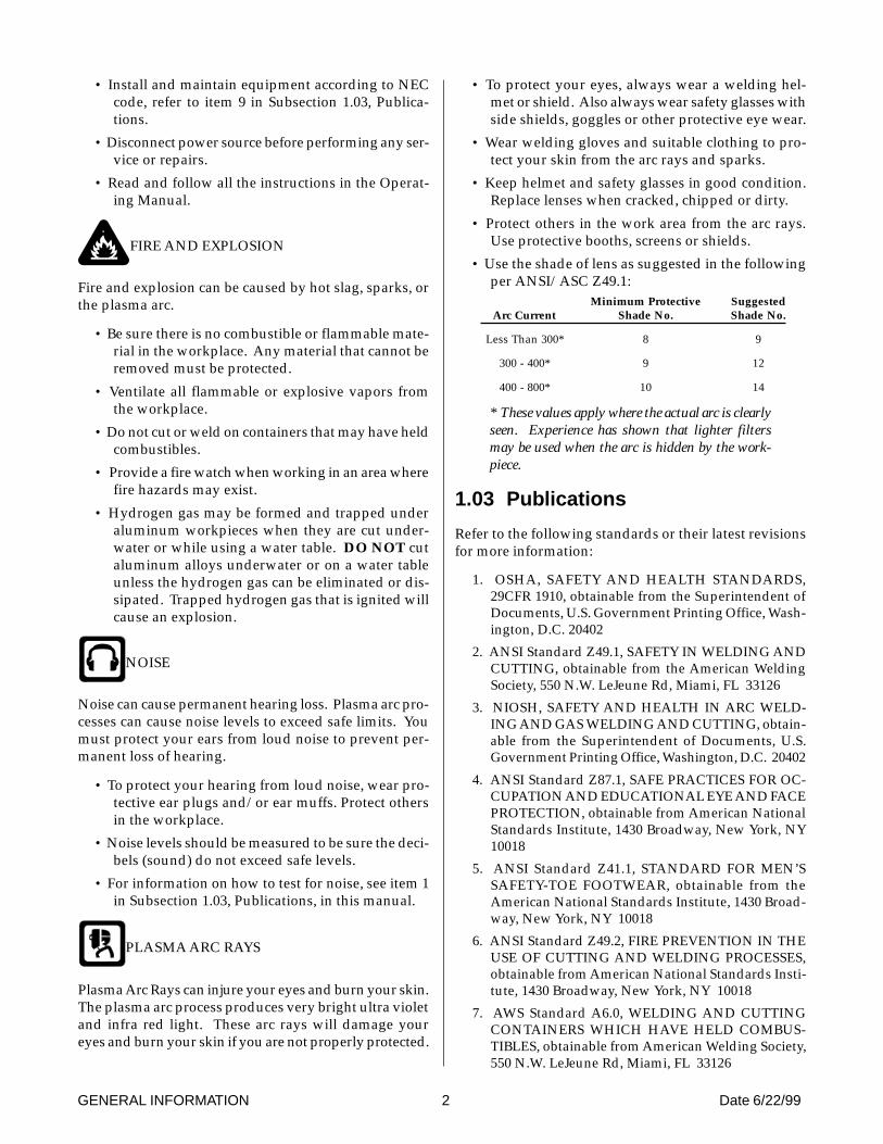
The following cut quality characteristics are illustratedin Figure 4-9 below:
Cut Surface
The condition (smooth or rough) of the face of the cut.
Bevel Angle
The angle between the surface of the cut edge and a planeperpendicular to the surface of the plate. A perfectly per-pendicular cut would result in a 0° bevel angle.
Top-Edge Rounding
Rounding on the top edge of a cut due to wearing fromthe initial contact of the plasma arc on the workpiece.
Dross Build-up and Top Spatter
Dross is molten material which is not blown out of thecut area and re-solidifies on the plate. Top spatter is drosswhich accumulates on the top surface of the workpiece.Excessive dross may require secondary clean-up opera-tions after cutting.
Kerf Width
The width of material removed during the cut.
Nitride Build-up
Nitride deposits which may remain on the surface of thecut when nitrogen is present in the plasma gas stream.Nitride buildups may create difficulties if the material iswelded after the cutting process.
SECTION 4: OPERATION 22 Manual 0-2784
Kerf WidthCut SurfaceBevel Angle
Top EdgeRounding
Cut SurfaceDrag Lines
DrossBuild-Up
TopSpatter
A-00007
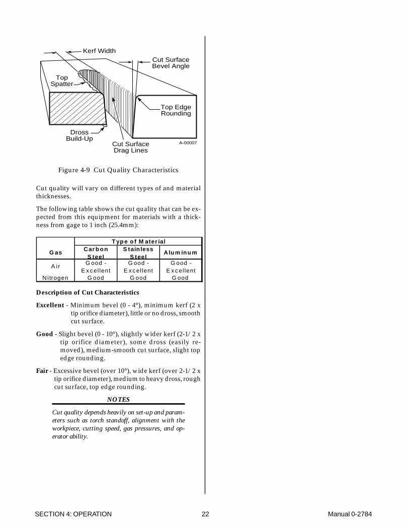
Figure 4-9 Cut Quality Characteristics
Cut quality will vary on different types of and materialthicknesses.
The following table shows the cut quality that can be ex-pected from this equipment for materials with a thick-ness from gage to 1 inch (25.4mm):
T yp e o f M ater ial
G as C ar b o nS teel
S tain lessS teel
A lu m in u m
A ir G ood -E x c el lent
G ood -E x c el lent
G ood -E x c el lent
N i trogen G ood G ood G ood
Description of Cut Characteristics
Excellent - Minimum bevel (0 - 4°), minimum kerf (2 xtip orifice diameter), little or no dross, smoothcut surface.
Good - Slight bevel (0 - 10°), slightly wider kerf (2-1/2 xtip orifice diameter), some dross (easily re-moved), medium-smooth cut surface, slight topedge rounding.
Fair - Excessive bevel (over 10°), wide kerf (over 2-1/2 xtip orifice diameter), medium to heavy dross, roughcut surface, top edge rounding.
NOTES
Cut quality depends heavily on set-up and param-eters such as torch standoff, alignment with theworkpiece, cutting speed, gas pressures, and op-erator ability.
Manual 0-2784 23 SECTION 5: SERVICE
SECTION 5:CUSTOMER/OPERATOR
SERVICE
5.01 Introduction
This section describes basic maintenance procedures per-formable by operating personnel. No other adjustmentsor repairs are to be attempted by other than ThermalDynamics Trained personnel.
For major troubleshooting and parts replacement proce-dures refer to PAK Master 100XL PLUS Power Supply(CE) Service Manual 0-2785.
5.02 General Maintenance
WARNING
Disconnect primary power to the system before dis-assembling the torch, leads, or power supply.
To clean the unit, open the enclosure (refer to Section 5.05-A, Opening Enclosure) and use a vacuum cleaner to re-move any accumulated dirt and dust. The unit shouldalso be wiped clean. If necessary, solvents that are rec-ommended for cleaning electrical apparatus may be used.
This schedule applies to all types of non-liquid cooledplasma cutting systems. Some systems will not have allthe parts listed and those checks need not be performed.
NOTE
The actual frequency of maintenance may need to be ad-justed according to the operating environment.
A. Maintenance Schedule
Daily Operational Checks or Every Six Cutting Hours:
1. Check torch consumable parts, replace if damagedor worn.
2. Inspect torch for any cracks or exposed wires, re-place if necessary.
3. Check plasma and secondary supply and pressure/flow.
4. Purge plasma gas line to remove any moisturebuild-up.
5. Inspect input power cable for damage or exposedwires, replace if necessary.
Weekly or Every 30 Cutting Hours:
1. Check fan for proper operation and adequate airflow.
2. Vacuum dust and dirt out of the entire machine.
CAUTION
Do not blow air into the power supply during clean-ing. Blowing air into the unit can cause metal par-ticles to interfere with sensitive electrical compo-nents and cause damage to the unit.
Six Months or Every 720 Cutting Hours:
1. Check the in-line air filter(s), clean or replace asrequired
2. Check cables and hoses for leaks or cracks, replaceif necessary.
3. Check all contactor points for severe arcing or pits,replace if necessary.
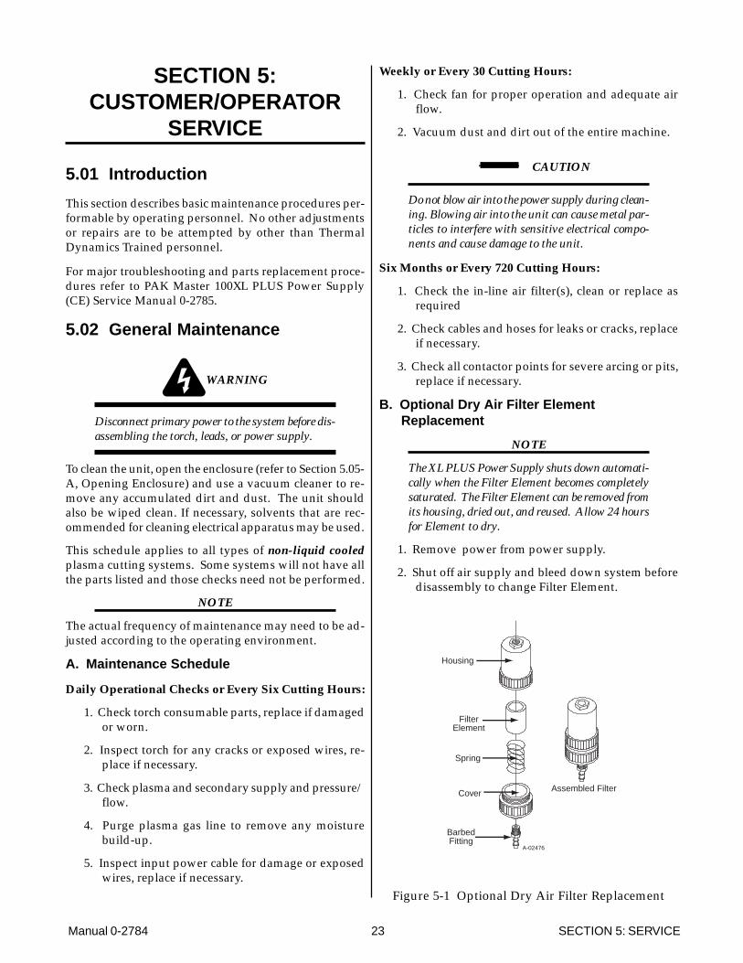
B. Optional Dry Air Filter ElementReplacement
NOTE
The XL PLUS Power Supply shuts down automati-cally when the Filter Element becomes completelysaturated. The Filter Element can be removed fromits housing, dried out, and reused. Allow 24 hoursfor Element to dry.
1. Remove power from power supply.
2. Shut off air supply and bleed down system beforedisassembly to change Filter Element.
A-02476
FilterElement
Housing
Cover
BarbedFitting
Spring
Assembled Filter
Figure 5-1 Optional Dry Air Filter Replacement
SECTION 5: SERVICE 24 Manual 0-2784
3. Disconnect gas supply hose from barbed fitting.
4. Turn the Cover counterclockwise and remove itfrom the Filter Housing. The Filter Element is lo-cated inside the Housing.
5. Remove the Filter Element from the Housing andset Element aside to dry.
6. Wipe inside of housing clean, then insert the re-placement Filter Element cup side first, as shownbelow.
7. Replace Housing on Cover.
8. Reattach gas supply hose to barbed fitting.
NOTE
If unit leaks between housing and cover, inspectthe "O" Ring for cuts or other damage.
5.03 Common Operating Problems
WARNINGS
Disconnect primary power at the source before dis-assembling the power supply, torch, or torch leads.
Frequently review the Important Safety Precau-tions (page 1). Be sure the operator is equipped withproper gloves, clothing, eye and ear protection.Make sure no part of the operator’s body comes intocontact with the workpiece while the torch is acti-vated.
CAUTION
Sparks from the cutting process can cause damageto coated, painted, and other surfaces such as glass,plastic and metal.
NOTE
Handle torch leads with care and protect them fromdamage.
A. Piloting
Piloting is harder on parts life than actual cutting becausethe pilot arc is directed from the electrode to the tip ratherthan to a workpiece. Whenever possible, avoid excessivepilot arc time to improve parts life.
B. Torch Standoff
Improper standoff (the distance between the torch tip andworkpiece) can adversely affect tip life as well as shieldcup life. Standoff may also significantly affect the bevelangle. Reducing standoff will generally result in a moresquare cut.
C. Edge Starting
For edge starts, hold the torch perpendicular to the work-piece with the front of the tip at the edge of the work-piece at the point where the cut is to start. When startingat the edge of the plate, do not pause at the edge andforce the arc to "reach" for the edge of the metal. Estab-lish the cutting arc as quickly as possible.
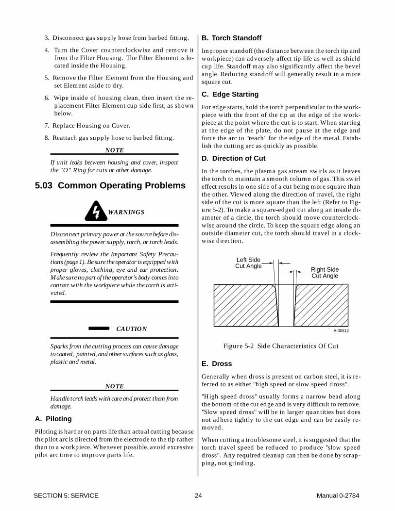
D. Direction of Cut
In the torches, the plasma gas stream swirls as it leavesthe torch to maintain a smooth column of gas. This swirleffect results in one side of a cut being more square thanthe other. Viewed along the direction of travel, the rightside of the cut is more square than the left (Refer to Fig-ure 5-2). To make a square-edged cut along an inside di-ameter of a circle, the torch should move counterclock-wise around the circle. To keep the square edge along anoutside diameter cut, the torch should travel in a clock-wise direction.
Right SideCut Angle
Left SideCut Angle
A-00512
Figure 5-2 Side Characteristics Of Cut
E. Dross
Generally when dross is present on carbon steel, it is re-ferred to as either "high speed or slow speed dross".
"High speed dross" usually forms a narrow bead alongthe bottom of the cut edge and is very difficult to remove."Slow speed dross" will be in larger quantities but doesnot adhere tightly to the cut edge and can be easily re-moved.
When cutting a troublesome steel, it is suggested that thetorch travel speed be reduced to produce "slow speeddross". Any required cleanup can then be done by scrap-ping, not grinding.

Manual 0-2784 25 SECTION 5: SERVICE
Dross present on top of the plate (top spatter), is normallycaused by a slow torch travel speed or too high of a torchstandoff distance.
F. Common Cutting Faults
1. Insufficient Penetration
a. Cutting speed too fast
b. Torch tilted too much
c. Metal too thick
d. Worn torch parts
e. Cutting current too low
2. Main Arc Extinguishes
a. Cutting speed too slow
b. Torch standoff too high from workpiece
c. Cutting current too high
d. Work cable disconnected
e. Worn torch parts
3. Excessive Dross Formation
a. Cutting speed too slow
b. Torch standoff too high from workpiece
c. Worn torch parts
d. Improper cutting current
4. Short Torch Parts Life
a. Oil or moisture in air source
b. Exceeding system capability (material too thick)
c. Excessive pilot arc time
d. Air flow too low (incorrect pressure)
e. Improperly assembled torch
5.04 Troubleshooting Guide
A. General
Troubleshooting and repairing this unit is a process whichshould be undertaken only by those familiar with highvoltage high power electronic equipment.
WARNING
There are extremely dangerous voltage and powerlevels present inside this unit. Do not attempt todiagnose or repair unless you have had training inpower electronics measurement and troubleshoot-ing techniques.
B. Basic Troubleshooting
This manual covers a basic level of troubleshooting thatrequires limited dissasembly and measurements. It ishelpful for solving many of the common problems thatcan arise with this system.
If major complex subassemblies are faulty, the unit mustbe returned to an authorized service center for repair.
Follow all instructions as listed and complete each sec-tion in the order presented.
For major troubleshooting and parts replacement pro-cedures refer to PAK Master 100XL PLUS Power Sup-ply (CE) Service Manual 0-2785.
C. How to Use This Guide
The following information is a guide to help the Cus-tomer/Operator determine the most likely causes forvarious symptoms.
This guide is set up in the following manner:
X. Symptom (Bold Type)
Any Special Instructions (Text Type)
1. Cause (Italic Type)
a. Check/Remedy (Text Type)
Locate your symptom, check the causes (easiest listed first)then remedies. Repair as needed being sure to verify thatunit is fully operational after any repairs.
A. Main power line fuses blow as soon as maindisconnect is closed
1. Input power cable not properly connected to customer'smain power panel
a. Check that input power cable is properly con-nected (refer to Section 3.05, Input Power Con-nections)

SECTION 5: SERVICE 26 Manual 0-2784
B. AC Power Indicator OFF
1. Switch at customer's main power panel in OFF posi-tion.
a. Close main power panel switch
2. Customer's main power line fuse(s) is blown
a. Check main power panel fuse(s) blown.
3. Unit internal fuse blown or loose
a. Fuse may blow if input voltage is higher thanvoltage requirements of unit. If blown, doublecheck input voltage vs. voltage requirementsof unit and replace fuse per Section 5.05-B. Iffuse blows again, components inside unit maybe faulty.
4. Faulty components in unit
a. Return unit to an authorized service center forrepair or have qualified technician repair perService Manual.
C. AC Power indicator ON; TEMP indicator ON
1. Airflow obstructed
a. Check for obstructed air flow and correct con-dition.
2. Fan blocked
a. Check and correct condition
3. Unit is overheated
a. Allow unit to cool down for about 5 minutes.Make sure the unit has not been operated be-yond duty cycle limit.
4. Input line voltage is below 75% of rated level
a. Check and connect to proper input power line
5. Faulty components in unit
a. Return for repair or have qualified technicianrepair per Service Manual.
D. Torch will not pilot when torch switch is activated
1. RUN/SET/LATCH switch in SET position
a. Move switch to RUN position.
2. Faulty torch parts
a. Inspect torch parts and replace if necessary (re-fer to Instruction Manual supplied with torch).
3. Gas pressure too high or too low
a. Set pressure to 70 psi (4.8 bar).
4. Faulty components in unit
a. Return for repair or have qualified technicianrepair per Service Manual.
E. AC Power indicator ON; Fans operating; TorchTrigger activated; No cutting output
1. Torch not properly connected to power supply
a. Check that torch leads are properly attached topower supply
2. Shield cup not properly installed on torch
a. Check that shield cup is fully seated againsttorch head (do not overtighten if screwed on)
3. Faulty components in unit
a. Return for repair or have qualified technicianrepair per Service Manual.
4. Faulty torch
a. Return for repair or have qualified technicianrepair per PCH/M-80 Torch InstructionManual, 0-2753.
F. Low cutting output with no control
1. Torch tip touching workpiece, tip saver active
2. Incorrect setting of CURRENT control
a. Check and adjusted to proper setting.
3. Faulty components in unit
a. Return for repair or have qualified technicianrepair per Service Manual.
G. Limited output with no control
1. Poor input or output connections
a. Check all input and output connections.
2. Incorrect setting of CURRENT control
a. Check and adjusted to proper setting.
3. Faulty components in unit
a. Return for repair or have qualified technicianrepair per Service Manual.
H. AC Power indicator ON; Cutting output available;Fans not operating
1. Fan blades blocked
a. Check and clear blades.
2. Faulty components in unit
a. Return for repair or have qualified technicianrepair per Service Manual.

Manual 0-2784 27 SECTION 5: SERVICE
I. AC POWER indicator ON; Fans operate; No gasflow
1. Gas not connected or pressure too low
a. Check source for at least 70 psi (4.8 bar).
2. Gas supply pressure too high
a. Max 125 PSI inlet pressure
3. Faulty components in unit
a. Return for repair or have qualified technicianrepair per Service Manual.
J. Torch cuts but not adequately
1. Drag circuit active
a. Lift tip from work piece.
2. Current set too low
a. Increase current setting.
3. Torch is being moved too fast across workpiece
a. Reduce cutting speed (refer to InstructionManual supplied with torch.
4. Excessive oil or moisture in torch
a. Hold torch 1/8 inch (3 mm) from clean surfacewhile purging and observe oil or moisturebuildup (do not activate torch)
5.05 Power Supply PartsReplacement
WARNING
Disconnect primary power to the system before dis-assembling the torch, leads, or power supply.
A. Left Side Panel Removal
1. Using a phillips head screw driver remove the fivescrews which secure the left side panel (viewedfrom front of unit) to the frame assembly.
A-02612
Left SidePanel
Screws(5 places)
Ground Wire
Figure 5-3 Left Side Panel Removal
NOTE
There is a ground wire connection to the Left SidePanel on the inside of the unit. There is no need todisconnect the ground wire.
2. Carefully pull the Left Side Panel up and awayfrom the unit to gain access to the inside of theunit.
3. To reinstall the left side panel do the following:
a. Place the left side panel onto the frame andslide the top edge under the lip on the top ofthe right side panel.
b. Reinstall all the screws to secure the left sidepanel.
B. Fuse Replacement
1. Remove the left side panel per paragraph "A"above.
2. Locate the internal fuse above the input power con-tactor on the left side of the unit.
3. Replace the fuse (0.8 amp, 600V).
4. Reinstall the left side panel per paragraph "A"above.
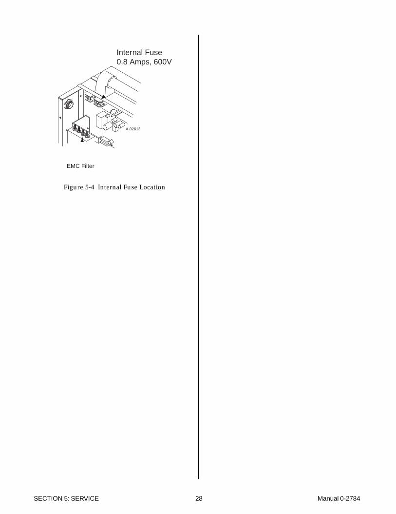
SECTION 5: SERVICE 28 Manual 0-2784
Internal Fuse0.8 Amps, 600V
A-02613
EMC Filter
Figure 5-4 Internal Fuse Location

Manual 0-2784 29 SECTION 6: PARTS LISTS
SECTION 6:PARTS LISTS
6.01 Introduction
A. Parts List Breakdown
The parts list provide a breakdown of all replaceable com-ponents. The parts lists are arranged as follows:
Section 6.03 Complete Power Supply Replacement
Section 6.04 Replacement Parts
Section 6.05 Options and Accessories
NOTE
Parts listed without item numbers are not shown,but may be ordered by the catalog number shown.
B. Returns
If a Thermal Dynamics product must be returned for ser-vice, contact your Thermal Dynamics distributor. Mate-rials returned to Thermal Dynamics without proper au-thorization will not be accepted.
6.02 Ordering Information
Order replacement parts by catalog number and completedescription of the part or assembly, as listed in the partslist for each type item. Also include the model and serialnumber of the torch. Address all inquiries to your autho-rized Thermal Dynamics distributor.

SECTION 6: PARTS LISTS 30 Manual 0-2784
6.03 Complete Power Supply Replacement
Power Supply includes work cable, input cable, pressure regulator/air filter, air hose and fittings, and operatingmanual.
Description Qty Catalog #
PAK Master 100XL PLUS Power Supply (CE)
380/415VAC, Three-Phase With EMC Input Cable (no plug) 1 3-0856
6.04 Replacement Parts
Qty Description Catalog #
1 Fuse (0.8 amp, 600V) 9-75261 220V Single-Phase Input Power Cable (CE) 9-7668
6.05 Options and Accessories
Qty Description Catalog #
1 Smart Cart 7-77771 Cutting Guide Kit 7-89101 Standoff Cutting Guide 8-75751 Filter Kit “Dry Air” 7-75071 Filter Body “Dry Air” 9-77401 Filter Element “Dry Air” 9-77411 Filter Hose “Dry Air” 9-77421 Two Stage Air Line Filter Kit 7-75001 Bracket, Laman Filter Mounting 9-75351 Dual Stage Air Filter Assembly 9-75271 First Stage Filter 9-10211 Second Stage Filter 9-1022
Computer Control Cable (CNC)1 25 Foot (7.6 m) 8-55571 50 Foot (15.2 m) 8-55581 Hand Pendant Control with 25 Ft. (15.2 m) 7-31141 Hand Pendant Extension Cable - 25 Ft. (15.2 m) 7-77441 Metal Mounting Tube with Pinion Assembly 7-7745
A-02476
FilterElement
Housing
Cover
BarbedFitting
Spring
Assembled Filter
Optional Dry Air Filter Assembly

Manual 0-2784 31 APPENDIX
APPENDIX I: INPUT WIRING REQUIREMENTS
NOTES
The table above is based on the following output current & voltage: 140VDC @ 80A
Refer to Local and National Codes or local authority having jurisdiction for proper wiring requirements.
Cable size is de-rated based on the Duty Cycle of the equipment.
The suggested sizes are based on flexible power cable with power plug installations. For hard-wired installationsrefer to local or national codes.
Cable conductor temperature used is 167° F (75° C).
An energy limiting fuse UL Class RK-1 (examples: BUSS LPS/LPN-RK or Gould-Shawmut AZK-A6K) should beused to minimize damage to Plasma Cutting, Welding or power distribution equipment.
NEVER use replaceable element fuses like UL Class H, or "one-time" fuses like UL Class K5.
Flexible cable must have an outside diameter of 0.69 inches (17.5 mm) or greater.
Input Power Input Current Input
Voltage Freq. 3-Ph 3-Ph Fuse (Amps) Wire (mm 2 )
(Volts) (Hz) (kVA) (Amps) 3-Ph 3-Ph380 50/60 19.1 29 35 10415 50/60 19.4 27 35 10
Line Voltages with Suggested Circuit Protection and Wire Sizes
Suggested Sizes (see notes)

APPENDIX 32 Manual 0-2784
APPENDIX II: SEQUENCE OF OPERATION(BLOCK DIAGRAM)
ACTION
ON/OFF switchto OFF
RESULT
All indicators off.Power supply fans off.
ACTION
RUN/SET/LATCHswitch to RUN.
RESULT
Gas flow stops. GAS indicator off.
ACTION
Torch moved within transfer distance of workpiece.
RESULT
Main arc transfer.Pilot arc off.
ACTION
Torch deactivated (by torch switch release or by remote device).
RESULT
Main arc stops.(Power supply enable signal removed.)
Gas flows (15 seconds)
NOTE - If torch is activated duringpost-flow, pilot arc will immediately restart. If torch is within transfer distance (3/8 in) of
workpiece, main arc will transfer.
After post-flow:
Gas solenoid closes, gas flow stops. GAS indicator off.
ACTION
Open external disconnect.
RESULT
No power to system.
ACTION
Close externaldisconnect switch.
RESULT
Power to system.
ACTION
RUN/SET/LATCH switch to SET.
RESULT
Gas solenoid open, gas flows to set pressure.
GAS indicator on.
ACTION
Torch moved away from work (while
still activated).
RESULT
Main arc stops.Pilot arc automatically
restarts.PILOT ARC
ACTION
ON/OFF switchto ON.
RESULT
AC indicator blinks for 8seconds then steady on.
Fans on. Power circuit ready.
ACTION
Protect eyes and activate torch
RESULT
Gas flows (2 seconds).
After gas pre-flow:
DC indicator on. Pilot relay closes.
Pilot arc established
A-02461
LATCH
ACTIONTorch Switch
can be released.
RESULTTransfer will continue until torch is removed
from workpiece.

Manual 0-2784 33 APPENDIX
This Page is Blank

APPENDIX 34 Manual 0-2784
APPENDIX III: SYSTEM SCHEMATIC
A-02639
INRUSH
GASGASSOL
INRUSH
(5)

Manual 0-2784 35 APPENDIX
A-02639
8/23/99
OK
OK TOMOVE
AB EC8397 HAS08/23/99

APPENDIX 36 Manual 0-2784