Embed Size (px)
Citation preview

Air-interface of high data rate wireless access
Narayanan Krishnamurthy1∗
under the guidance of Dr. Prashant Krishnamurthy2∗
Abstract. High data rate, reliable wireless access has been the focus in the design of
the future wireless broadband communications. The wireless access is increasingly becoming
data centric, and has to meet the requirements of a wide array of traffic ranging from voice,
multimedia, and other real-time applications.
The technology that work behind the scenes to make all this happen is constantly im-
proving; improvements in the physical layer including new coding and modulation schemes
that use spatial multiplexing (transmitting and receiving signals through multiple antennas),
and improvements in medium access strategy (currently physical agnostic) is analyzed.
The role of MIMO MAC and inter-layer interactions in wireless open system interface are
identified, to lay the framework for a cross-layer design, of a physical aware medium access
layer.
Key words. Multiple Input Multiple Output(MIMO) wireless communication, Space-
Time coding(STC), Orthogonal Frequency Division Multiplexing(OFDM), Wireless Local
Area Network(WLAN), Cross-Layer design
∗1 Department of Electrical and Computer Engg. 2*Associate Professor School of Information Sciencesand Telecommunications University of Pittsburgh, Pittsburgh, PA 15261
1
Air-interface of high data rate wireless access 2
Contents
1 Introduction 3
2 Fading in communication channels 4
2.1 Impulse response of channel, selectivity and distortion . . . . . . . . . . . . . 5
2.2 Mathematical Model of Rayleigh Fading . . . . . . . . . . . . . . . . . . . . 6
2.3 Instantaneous SNR per bit and Probability of Error . . . . . . . . . . . . . . 7
3 Mitigation of channel impairment 9
3.1 Combat frequency-selective fading distortion . . . . . . . . . . . . . . . . . . 9
3.2 Combat loss in SNR due to frequency-flat fading . . . . . . . . . . . . . . . . 10
4 Spatial diversity 10
4.1 Receiver Diversity . . . . . . . . . . . . . . . . . . . . . . . . . . . . . . . . . 11
4.1.1 Selection and Switched Diversity . . . . . . . . . . . . . . . . . . . . 11
4.1.2 Linear Combination Receiver, Equal Gain and Maximal Ratio . . . . 12
4.2 Transmitter Diversity . . . . . . . . . . . . . . . . . . . . . . . . . . . . . . . 14
4.2.1 Delay Diversity . . . . . . . . . . . . . . . . . . . . . . . . . . . . . . 14
4.2.2 Alamouti Orthogonal Space-Time Block Coding . . . . . . . . . . . . 14
4.2.3 Space-Frequency Coding: Orthogonal Frequency Division Multiplex-
ing(OFDM) . . . . . . . . . . . . . . . . . . . . . . . . . . . . . . . . 17
4.3 Advantages of Spatial Diversity . . . . . . . . . . . . . . . . . . . . . . . . . 19
4.3.1 Increased Reliability a MIMO Link . . . . . . . . . . . . . . . . . . . 20
4.3.2 Increased Range of a MIMO link . . . . . . . . . . . . . . . . . . . . 20
4.3.3 Increased Capacity of MIMO systems . . . . . . . . . . . . . . . . . 21
5 Medium Access strategies in wireless access networks 23
5.1 QoS Support in wireless LAN’s . . . . . . . . . . . . . . . . . . . . . . . . . 24
5.2 Cross-Layer design perspective . . . . . . . . . . . . . . . . . . . . . . . . . . 25
6 Role of MIMO aware MAC 26
6.1 Review of MIMO MAC Design by P Ramanathan, B V Veen and et.al [24] . 26
7 Conclusion 27
Air-interface of high data rate wireless access 3
A Large-scale Path Loss Models 30
A.1 Path loss in free space: . . . . . . . . . . . . . . . . . . . . . . . . . . . . . . 30
A.2 Two Ray Reflection model: . . . . . . . . . . . . . . . . . . . . . . . . . . . . 30
A.3 Indoor Propagation: Attenuation Factor Model . . . . . . . . . . . . . . . . 32
1 Introduction
The increasing popularity of wireless hot-spots and WLAN’s can be attributed to features
like mobility, high data rates and quality of service (QoS) that attracts the end user as much
as the ease of deployment and scalability advantages that attracts the service providers. The
technology alternatives that work behind the scenes to make it all possible are constantly
improving. The improvements are across the layers of the open system interface (OSI), and
work in tandem to ultimately realize the high data rate wireless access networks.
Improvements in the air interface or the physical layer, permit improved options like
smart-multiple antennas, and a choice from the myriad coding and modulation schemes.
Each scheme professes an edge over the others, to varying degrees, in terms of its effectiveness
with respect to spectral usage, or its immunity to interference. As we shall see in section
4.2.2 Multiple input and Multiple output (MIMO) communications using space-time coding,
and multi-carrier orthogonal frequency division multiplexing(OFDM) - section 4.2.3, are at
the forefront in air-interface design for high data rate wireless access.
Improvements in medium access(MAC) strategies, have to take into account the perfor-
mance limiting challenges of the wireless channel(time varying delay and Bit Error Rate(BER)).
Additionally it would have to support a variety of services ranging from voice, short text, to
video and audio streaming with their specified Quality of Service(QoS), in terms of delay,
throughput and BER. A cross-layer design, for instance a physical(PHY) aware medium
access(MAC) and data link layer can be used to better utilize radio resources(power and
bandwidth), combat network congestion and facilitate handoff procedures.
Higher layers are likewise not left out in the changes designed to provide mobility and
improved end to end throughput of the next generation wireless networks. Improved routing
strategies can be developed for a multi-hop network with the knowledge of channel state
information viz., received signal and interference level, number of active users etc. Thus new
routes discovered based on additional link state information, can be more effective over those
discovered merely using hop-distance information.
This report is organized into three major sections. The first section delves into the

Air-interface of high data rate wireless access 4
Figure 1: Small-scale and Large-scale spatial channel fading
characterization of the wireless channel in terms of mathematical models. The second part is
about strategies to overcome the channel impairment, discussed in the first section. Emphasis
is placed on space-time coding for MIMO communications as the strategy of preference, while
mentioning the other traditional and newer alternatives, to combat the foes of the wireless
channel. The final section deals with issues involved in the design of PHY aware MAC
to meet the varied QoS requirements(in terms delay, throughput and BER), that the next
generation wireless networks would have to support.
2 Fading in communication channels
Fading is the term used to describe the rapid fluctuations in the amplitude of the received
radio signal over a short period of time. Fading is a common phenomenon in Mobile Com-
munication Channels, and it is caused due to the constructive and destructive interference
between two or more versions of the transmitted signals which arrive at the receiver at slightly
different times. The resultant received signal can vary widely in amplitude and phase, de-
pending on various factors such as the intensity, relative propagation time of the waves,
bandwidth of the transmitted signal etc. The figure 1 summarizes the effects of fading, we
will now look into mathematical models to characterize small-scale fluctuations in amplitude
and phase of the received signal. See Annex A for the large-scale signal deterioration models.

Air-interface of high data rate wireless access 5
2.1 Impulse response of channel, selectivity and distortion
The channel induced attenuation in amplitude, phase distortion and propagation delay, can
be mathematically modeled as a time varying linear system, whose impulse response is:
h(t) = a(t)ejθ(t)δ(t − τ) (2.1)
The above expression for impulse response of a channel is just a scaled impulse in time
which corresponds to channel loss/gain a(t) and channel induced propagation delay τ .
The output from this linear system model is the attenuated shifted response that the
receiver sees, a result of convolution with the impulse response.
y(t) = h(t) ∗ x(t), (2.2)
x(t) is the transmitted signal
y(t) is the received signal
The multiple paths in a wireless system can be modeled as an aggregation of impulses
due to the K-paths in the channel.
h(t) =
K∑
i=1
ai(t)ejθi(t)δ(t − τi) (2.3)
where ai(t) : is the channel loss/gain of path i
and τi : is the propagation delay of path i
The characterization of a channel into flat or frequency-selective is based on whether the
the multi-path is resolvable or unresolvable, if Tm is the maximum excess delay amongst the
multiple paths, and Ts is the transmission time of the symbol.
• A channel is considered frequency-selective when Tm > Ts, i.e the received multi-
path components extend beyond the symbol duration and cause inter symbol interfer-
ence(ISI).
• While the channel is considered to be frequency-flat when Tm < Ts, i.e the multi-
path components arrive within the symbol duration and hence there is no channel
induced ISI. There may sill be a loss in SNR due to the destructive interference of the
multi-path symbols.

Air-interface of high data rate wireless access 6
Thus while frequency-selective fading induces ISI distortion, flat fading may result in loss
of SNR of the received signal [21].
2.2 Mathematical Model of Rayleigh Fading
Consider a transmitted signal s(t) = Acos2πfct through a fading channel. The received
signal can be expressed as (ignoring the effects of noise):
y(t) = A
N∑
i=1
ai cos(2πfct + θi) (2.4)
where ∗ ai is the attenuation of the ith multi path component
∗ θi is the phase-shift of the ith multi path component
∗ ai and θi are random variables
Thus expression 2.4 is re-written as:
y(t) = A
(
N∑
i=1
ai cos(θi)
)
cos(2πfct) −(
N∑
i=1
ai sin(θi)
)
sin(2πfct)
(2.5)
We introduce two random processes X1(t) and X2(t), such that the above equation becomes:
y(t) = A X1(t) cos(2πfct) − X2(t) sin(2πfct) (2.6)
If the value of N is large (i.e, a large number of scattered waves are present), invoking
the Central- Limit Theorem, we get approximate X1(t) and X2(t) to be Gaussian random
variables with zero-mean and variance σ2. The expression 2.6 can be re-written as:
y(t) = AR(t) cos(2πfct + θ(t)) (2.7)
where, The amplitude of the received waveform R(t) is given by:
R(t) =√
X1(t)2 + X2(t)2 (2.8)

Air-interface of high data rate wireless access 7
Since the processes X1(t) and X2(t) are Gaussian, it can be shown that R(t) has a Rayleigh
Distribution with a probability density function(pdf) given by: see p181,p190 Papoulis [17]
fR(r) =r
2σ2exp
−r2
2σ2
, r > 0 (2.9)
and, The phase of the received waveform θ(t) is given by:
θ(t) = tan−1
(
X2(t)
X1(t)
)
(2.10)
Since the processes X1(t) and X2(t) are Gaussian, it can be shown that θ(t) has a Uniform
Distribution with a probability distribution function(pdf) given by:
fθ(θ) =1
2π, −π ≤ θ ≤ π (2.11)
The distortion in the phase can be easily overcome if differential modulation in employed. It
is the amplitude distortion R(t) that severely degrades performance of digital communication
systems over fading channels. It is usually reasonable to assume that the fading stays
essentially constant for at least one signaling interval.
2.3 Instantaneous SNR per bit and Probability of Error
Probability of Error in AWGN: The probability of error in symbols transmitted
can be determined from the minimum distance of the modulation used and the number
of nearest neighbors in the signal constellation, for the AWGN channel the probability of
error(Pe) for Binary PSK is given by:
Pe(γb) = 2Q(
√
2γb
)
where γb =Eb
Nofor AWGN (2.12)
Probability of Error in AWGN+Rayleigh Fading: Since it is assumed that the
fading stays constant in a signaling interval, we can represent the fading phenomenon using
a random variable R. Since only amplitude distortion is considered, the instantaneous SNR
per bit γb is now a random variable given by:
γb = R2 Eb
No(2.13)

Air-interface of high data rate wireless access 8
Since R is Rayleigh distributed, R2 and in turn γb has a chi-squared distribution with two
degrees of freedom, which is an exponential distribution whose pdf is given by:
fγb(γb) =
1
γb
exp
−γb
γb
, γb ≥ 0 (2.14)
Where γb is the average SNR per bit, and is given by:
γb =Eb
NoE[R2] (2.15)
So, the average probability of error, given the pdf of the random variable γb can be found
directly as:
Pe =
∫ ∞
0
Pe(γb)fγb(γb)dγb (2.16)
for Binary PSK the above expression reduces to: from Rappaport [19],
Pe =1
2
(
1 −√
γb
1 + γb
)
, for γb 1,
where γb is defined in 2.15, Pe reduces to: (2.17)
Pe ≈ 1
4γb
(2.18)
The destructive effect of fading is evident from the above equation. The value of Pe
decreases linearly with increasing SNR per bit, rather than either a Q-function type or an
exponential decrease. This will severely degrade the power-efficiency of a digital communi-
cation system if preventive measures are not taken to mitigate this problem.
The figure 2 illustrates this steep deterioration of the channel due to Rayleigh Fading
when compared with additive white Gaussian noise(AWGN) channel. A 3dB SNR is ade-
quate to support Bit Error Rates(BER) of 0.02 when there is no channel fading in AWGN
channel, in contrast a 10dB SNR is required to support the same 0.02 BER using Binary
PSK modulation scheme - which is a loss of 7dB due to fading.
Note: Though we have nice closed form expressions for BER or Pe for BPSK, we can
arrive at similar performance curves using Monte-Carlo simulation by generating Raleigh
and Gaussian random variates, and arrive at the statistical averages, by averaging over a
large number of trials (restricted by the random number generator’s capability to generate
iid variates). Figure 2 performance curves, comparing AWGN and Raleigh Fading were
obtained using the above mentioned closed form expressions, while figure 12 performance

Air-interface of high data rate wireless access 9
0 1 2 3 4 5 6 7 8 9 1010
−6
10−5
10−4
10−3
10−2
10−1
100
SNR per Bit ( γb) −−−−>
BE
R −
−−−>
Performance of AWGN and Rayleigh Fading Channels
AWGN ChannelFading Channel
7db Loss
Figure 2: AWGN and Rayleigh Fading Performance
curves, for improvements due to transmit and receiver diversity, were obtained using Monte-
Carlo simulation.
3 Mitigation of channel impairment
The previous sections detailed the physics of radio propagation and the theory behind channel
fading and inter symbol interference(ISI) distortion. Additionally, the non-engineerable and
non-clonable radio space is also affected by interference from multiple users sharing the
same medium. Listed below are strategies summarized by [22] to alleviate the hostile radio
environment, by carefully designed coding and modulation schemes.
3.1 Combat frequency-selective fading distortion
• Adaptive equalization, decision feedback Viterbi equalizer
• Spread Spectrum(SS) -Direct Sequence(DS) or Frequency Hopping(FH)
• Orthogonal Frequency Division Multiplexing(OFDM)

Air-interface of high data rate wireless access 10
• Pilot Signal (Channel Estimation)
• Robust Modulation, Coding and Interleaving
3.2 Combat loss in SNR due to frequency-flat fading
Traditionally, some type of diversity has been employed to get additional uncorrelated esti-
mates of the signal to combat the deterioration in SNR due to fading. The different types
of diversity are:
• Temporal-diversity, redundancy in time e.g. coding, interleaving.
• Frequency redundancy or bandwidth expansion e.g. Spread Spectrum, DS and FH.
Both time and frequency diversity trade bandwidth for performance viz. bit error-
rate.
• Spatial diversity uses multiple transmit and/or receive antenna, to improve perfor-
mance without loss in bandwidth.
• Polarization of E-field is also used as additional dimensions to improve diversity. It is
either horizontal or vertical depending on the relative orientation of the field to the
direction of propagation.
Though traditional schemes like adaptive decision feedback equalization and spread spec-
trum, and other new coding and modulation strategies like OFDM and Time Reversed STBC
counter distortion and interference, emphasis is placed on orthogonal space-time coding pro-
posed by Alamouti in this report.
4 Spatial diversity
The basic idea in using multiple antennas in the transmission and reception of uncorrelated
copies of the signal is the increased probability in MIMO systems that at least one of them
is of good quality, despite deep-fade in the channel.
In order to tap the above mentioned processing gain in MIMO systems, an optimal
signal combining strategy at the receiver, and a handcrafted orthogonal signal design at the
transmitter should be employed. Orthogonal Space-Time coding proposed by Alamouti and
further generalized by Tarokh et.al [12] is needed to prevent multiple copies of the signal,
arriving at the receiver, from interfering with one another.

Air-interface of high data rate wireless access 11
Figure 3: Selection and Switched Diversity
4.1 Receiver Diversity
The first system to incorporate spatial diversity was at the access point or the base sta-
tion. The access point had no weight, size or power limitations (unlike the mobile users),
to implement the multi-antenna systems. The economics of sharing the cost of hardware
upgrade amongst the multiple users also motivated the development of the multiple antenna
base stations. The receiver diversity at the access point leads to an increase in the up-link
capacity(from mobile user to the access point) and was incorporated into GSM and IS-136
standards.
4.1.1 Selection and Switched Diversity
The switched antenna diversity was amongst the earliest diversity techniques used at the
access point, the antenna’s are separated by distances greater than λ2
to ensure a certain
degree of independence in their reception. When the SNR falls beneath a threshold for
useful detection, the RF path was switched to the alternate path to receive the transmission
despite the signal fade in the earlier path, see figure 3.
The hard switch when replaced by a soft decision; results in the selection combining
receiver. It works on similar lines, and utilizes the fact that not all of the independent paths
will fade simultaneously. Thus when the signal SNR falls beneath the threshold for correct
decoding; the alternate antennas are scanned to choose the one with highest SNR.

Air-interface of high data rate wireless access 12
4.1.2 Linear Combination Receiver, Equal Gain and Maximal Ratio
Maximal-ratio combining(MRC), and equal gain combining are linear combining strategies at
the receiver. Assuming a flat fading channel that precludes ISI, a linear combination strategy
involves co-phasing the received signals by appropriate choice of weighting coefficients that
would ultimately maximize the SNR of reception, the MMSE receiver also optimizes the
weighting coefficients to this end. See figure 4 for the structure of the maximal combining
receiver.
The received signals are:
y0[k] = h0x[k] + n0[k] (4.1)
y1[k] = h1x[k] + n1[k] (4.2)
where x[k] = sn is the transmitted signal during symbol interval k, and h0,1 = α0,1ejφ0,1
is the quasi static channel response that is assumed to remain unchanged during a symbol
interval. n0,1[k] are the additive noise terms.
The MRC chooses weighting coeffs ai to combine the signals received in all the branches:
y[k] =
Nr−1∑
i=0
aiyi[k] (4.3)
= x[k]Nr−1∑
i=0
aiαiejφi +
Nr−1∑
i=0
aini[k] (4.4)
substituting x[k] = sn in 4.4, the SNR of the MRC, γmrc is:
γmrc =E[
|sn
∑Nr−1i=0 aiαie
jφi|2]
E[
|∑Nr−1
i=0 aini[k]|2] (4.5)
using Cauchy-Schwartz the upper bound on the SNR obtained in MRC is found by
reducing 4.5 to:
γmrc ≤(
Ex
N0
)Nr−1∑
i=0
α2i , when ai ∝ αie
−jφi (4.6)
γmrc =
(
Ex
N0
)Nr−1∑
i=0
α2i , i.e. meets the upper bound (4.7)

Air-interface of high data rate wireless access 13
Figure 4: Maximal Ratio Combining Receiver
The MRC produces an estimate of the transmitted wave form sn:
sn = h∗0y0[k] + h∗
1y1[k] (4.8)
= (α20 + α2
1)sn + h∗0n0[k] + h∗
1n1[k] (4.9)
Performance of MRC receiver: A closed form expression of the performance of MRC
reciever when using BPSK modulation is provided in [26], which are obtained in similar lines
as the probability of error calculation for Rayleigh fading in section 2.3, approximate Pe for
γb 1, where nR is the number of receivers:
Pe ≈(
1
4γb
)nR(
2nR − 1
nR
)
(4.10)
Note: The complexity of the maximal ratio combiner in estimating the channel gain/loss
and conjugating it to obtain the weighting coefficients ai is avoided in the equal gain com-
biner, where ai = e−jφi is chosen to be equal for all the branches. The simplicity of this
receiver is preferred over the slight loss in performance due to sub optimality.

Air-interface of high data rate wireless access 14
Figure 5: Transmit Delay Diversity Scheme
4.2 Transmitter Diversity
The 3G Partnership Project (3GPP) is looking into the open loop and closed loop variants
of transmitter diversity to increase the down-link capacity (from the access point to the
mobile user)[7]. Transmitter diversity as mentioned earlier has to have specific orthogonality
requirements. In the open loop design, the transmitter is not aware of the channel state,
while in the closed loop design the receiver reports the Rayleigh attenuation coefficients and
the delays associated with the multiple paths, by decoding special pilot signals this process
is called Channel Estimation.
4.2.1 Delay Diversity
Delay diversity transmit scheme first proposed by Wittneben and simultaneously by Winters,
the scheme involves the creation of a multi-path environment intentionally. It incorporates
delay elements at the multiple Tx antenna to create the multi-path environment, see figure
5. The processing gain achieved by the delayed diversity is realized by using an equalizer at
the receiver.
4.2.2 Alamouti Orthogonal Space-Time Block Coding
Space-time codes(STC), are orthogonal signal design technique that utilize the added spatial
dimension of multi-antenna systems in coding. There are two classes of STC viz. state-
time block code(STBC) first proposed by Alamouti and the state-time trellis codes(STTC)
proposed by Tarokh e.t.al. The simplicity and linear processing at the receiver when using

Air-interface of high data rate wireless access 15
Figure 6: Alamouti Transmitter Diversity
STBC is preferred over the exponentially increasing complexity of the STTC, which involves
convolution encoding and Viterbi decoding. We will only look into STBC in this report .
2Tx-1Rx Alamouti encoder The figure 6 gives the structure of STBC with two
transmit antennas. The essence of Space-Time coding for trasmit diversity lies in hand-
crafting signals which are orthogonal in the chosen dimensions, such that they do not interfere
with one other, when they arrive simultaneously at the receiver.
The transmission of two symbols occurs simultaneously through the two Tx antenna’s
over two time intervals(hence full-rate). The first(even) interval two of the incoming sym-
bols is transmitted, the following(odd) interval complex conjugates of the two symbols are
transmitted as shown in figure 7:
Let Sn be the sequence of symbols to be transmitted. Let x0[k], x1[k] be the signals
transmitted by antenna zero and antenna one respectively at time instant k. Thus the
transmissions at k and k+1 are:
x0[k] = sn, x1[k] = sn+1 (4.11)
x0[k + 1] = −s∗n+1, x1[k + 1] = s∗n (4.12)
Channel is assumed to fade slowly, i.e. remains constant over two symbol durations:
h0[k + 1] = h0[k] = h0 = α0ejφ0 (4.13)
h1[k + 1] = h1[k] = h1 = α1ejφ1 (4.14)

Air-interface of high data rate wireless access 16
Figure 7: Transmitter Diversity,Space-Time Coding
Figure 8: Alamouti-Receiver-Combiner
thus the received signal is:
y[k] = h0x0[k] + h1x1[k] + n[k] (4.15)
2Tx-1Rx Alamouti decoder The decoder utilizes the specific transmission sequence
to decode the orthogonal signals iteratively. ML decoding in the AWGN case with no ISI
reduces to minimum distance decoding. Since the receiver estimates the channel from the
pilot transmissions, the received estimates can be divided by the channel gain to obtain the
Air-interface of high data rate wireless access 17
transmitted signal estimate, when the receiver combines the received signals as follows:
sn = h∗0y[k] + h1y
∗[k + 1] (4.16)
sn+1 = h∗1y[k] − h0y
∗[k + 1], reduces to: (4.17)
sn = (α20 + α2
1)sn + h∗0n[k] + h1n
∗[k + 1] (4.18)
sn+1 = (α20 + α2
1)sn+1 + h∗1n[k] − h0n
∗[k + 1] (4.19)
A general technique for constructing STBC for any number of transmitters was formu-
lated by Tarokh et.al. These codes still retain the ML decoding and it was shown that it is
possible to construct full rate STBC for real signal constellations. For example the STBC
mapper for four transmit antenna with rate 4/8 is given below:
s1
s2
s3
s4
→
s1 −s2 −s3 −s4 s∗1 −s∗2 −s∗3 −s∗4
s2 s1 s4 −s3 s∗2 s∗1 s∗4 −s∗3
s3 −s4 s1 s2 s∗3 −s∗4 s∗1 s∗2
s4 s3 −s2 s1 s∗4 s∗3 −s∗2 s∗1
(4.20)
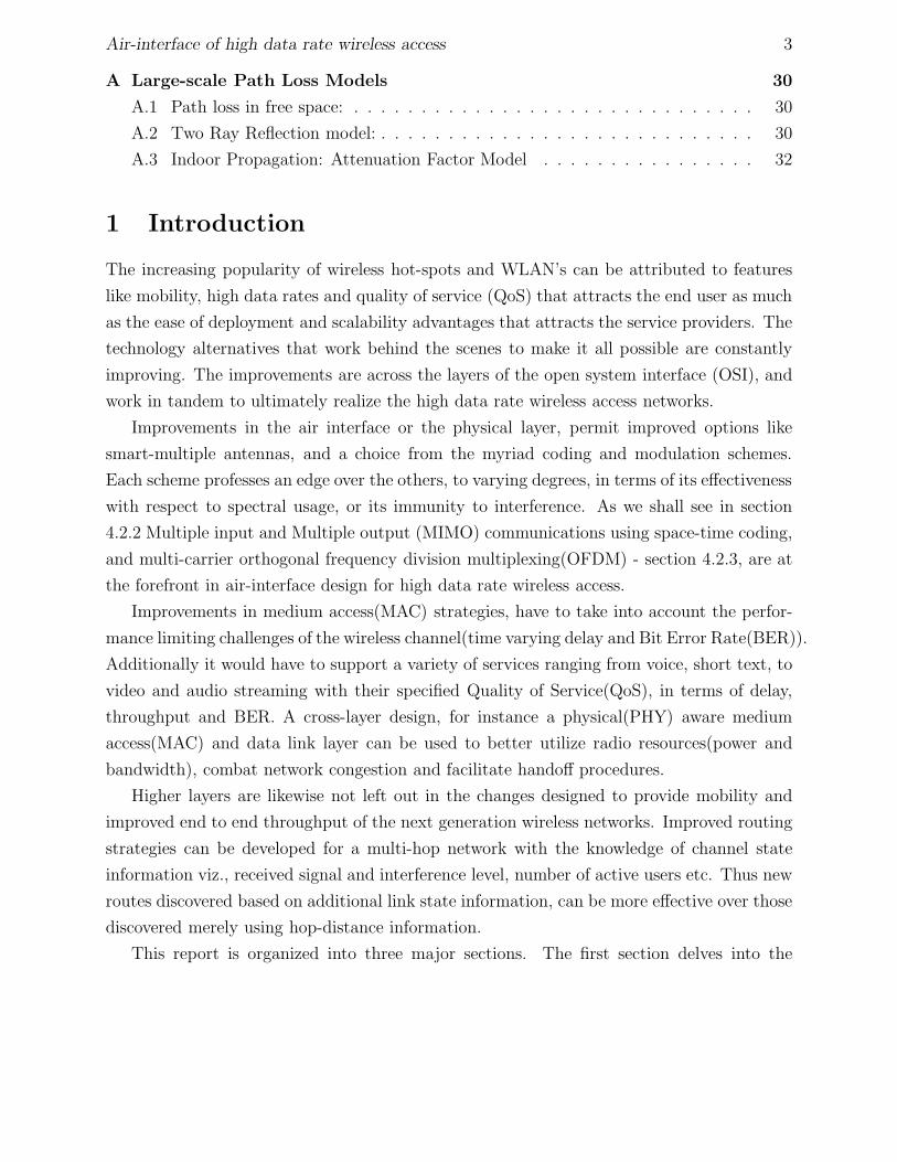
4.2.3 Space-Frequency Coding: Orthogonal Frequency Division Multiplexing(OFDM)
The flat-frequency channel model assumed by Alamouti space-time coding fails in the case
of wideband transmissions. At high data rates the symbol duration is much smaller than the
excess delay-spread due to fading. Space-Frequency coding(SFC) is a strategy that uses the
transmitter diversity technique proposed by Alamouti for freq-selective fading channels. SFC
uses the adjacent subbands of the channel in an OFDM structure instead of adjacent times
in the STBC proposed by Baraniuk e.t.al [1]. See figure 9 for the structure of SF-OFDM
scheme.
OFDM is a multi-carrier communication technique wherein, a single stream of input data
is split into multiple streams using a serial to parallel converter at the transmitter. Each sub-
stream is modulated onto orthogonal subbands using Inverse Fast Fourier Transform(IFFT).
The orthogonal waveforms despite its overlap in the frequency domain can be successfully
demodulated at the receiver using the inverse transformation (FFT) provided there is no In-
ter symbol Interference(ISI) or Inter subband Interference. Guard bands and cyclic prefixes
are introduced in the modulation scheme to prevent Inter symbol Interference(ISI) and inter
subband interference[9]. See figure 11 to see how the guard interval precludes inter sym-
bol interference(ISI) while cyclically extending the data into the guard intervals prevents

Air-interface of high data rate wireless access 18
Figure 9: Transmitter Diversity for Frequency Selective Channels using SF-OFDM
Figure 10: OFDM Transmission Reception

Air-interface of high data rate wireless access 19
Figure 11: Guard Interval precludes ISI while Cyclic Prefix Prevents Inter Subband Inter-ference
spurious high frequency components (also called inter subband interference, due to sharp
discontinuities) from being introduced in the signal. The cyclic prefix that was added in
the transmission is removed, before inverse orthogonal transformation (FFT) and ultimate
parallel to serial conversion at the receiver, to recover the original data stream. See figure
11 for the overall structure of the OFDM transmission and reception. Further details on the
space-frequency OFDM, or on other techniques like time-reversed STBC for freq-selective
channels is beyond the scope of this report.
4.3 Advantages of Spatial Diversity
The processing gain achieved in MIMO systems, is realized into the following reliability and
capacity gains:
1. Increased reliability of the wireless link. The array gain of MIMO systems and SNR
increase due to it, increases the robustness of the wireless link by decreasing the outage
probability and the associated Bit Error Rate(BER) in the transmission. The outage
probability has been shown by Laneman[11] to be proportional to 1SNRN for N=2, where
N is the diversity order of the system.
2. Increased capacity/range for given transmitter power and bandwidth constraint. The
spatial diversity utilizes the multiple data pipes and thereby increases the spectral

Air-interface of high data rate wireless access 20
0 2 4 6 8 10 1210
−5
10−4
10−3
10−2
10−1
100
SNR per Bit (γb) −−−−>
BE
R −
−−
−>
Performance of receivers in AWGN and Rayleigh Fading Channels: No−Diversity, Rx and Tx−Diversity
AWGN−No−DiversityRayleigh−No−DiversityAlamouti−Tx Diversity(2Tx−1Rx)Maximal Ratio−Rx Diversity(1Tx−2Rx)
3db loss
Figure 12: BER improvement with diversity
efficiency of the system, without increasing the power and bandwidth requirements.
4.3.1 Increased Reliability a MIMO Link
The increased reliability of a MIMO link can be seen in the figure 12. The figure shows that
the maximal-ratio combiner performs 3dB better over the transmit diversity scheme with
an equivalent diversity-order (N) of two. The loss in performance of the transmit diversity
can be attributed to the fact that, only half of the power is radiated from each transmit
antenna(when N = 2), this normalization is done to keep the received power constant, and
independent of the number of transmitters.
4.3.2 Increased Range of a MIMO link
Smart antennas provide enhanced coverage through range extension, hole filling and better
building penetration [14]. Given the same transmitter power output at the base station and
subscriber unit, smart antennas can increase range by increasing the gain of the base station
antenna. From the path loss models discussed in Annex A, the uplink power received from

Air-interface of high data rate wireless access 21
a mobile unit at a base station is:
Pr = Pt + Gs + Gb − PL (4.21)
where Pr is the power received at the base station, Pt is the power transmitted by the
subscriber, Gs is the gain of the subscriber unit antenna and Gb is the gain of the base
station antenna. On the uplink, if a certain power Pr,min, is required at the base station, by
increasing the gain of the base station - Gb, the link can tolerate greater path loss PL. Using
expressions for path loss from AnnexA:
PL(d) = PL(d0) + 10nlog
(
d
d0
)
+ Xσ (4.22)
Thus by increasing the tolerable path loss, one can increase the reception range, d of the
base station.
4.3.3 Increased Capacity of MIMO systems
The capacity bound on communication systems developed my Shannon as C = Blog2(1 +
SNR), can be extended to analyze MIMO systems. The Shannon’s transmission rate bound
C, is limited by the bandwidth B of the communication system, and the transmission signal
to noise ratio(SNR).
The characterization of the multi-path channel as a time varying linear system with a
complex impulse response h is used to model the received observations(refer section 2.1 on
flat-frequency scaled impulse model):
y = hHs + n, s : signal, n : AWGN (4.23)
Capacity of a SISO Link: The received signal strength from equation 2.3 is thus hs
and the power would be h2E[s2], from which the capacity of a SISO system(single transmit
and receive antenna) is found as:
C = log2(1 + ρ|h|2) (bits/s/Hz) (4.24)
where ρ is the SNR at the receive antenna, and h is the complex gain of the single channel.

Air-interface of high data rate wireless access 22
Capacity of a SIMO Link: The channel model 4.23 can also be used to model multiple
paths of SIMO or receiver diversity system. The Maximum Likelihood(ML) receiver statistic
reduces to minimizing the exponent of the Gaussian random variable :
||y − hs||2 = ||y||2 + |s|2||h||2 − 2Re[s∗hHy] (4.25)
= ||h||2[
s − hHy
||h||2]2
+ const, (completing the square) (4.26)
= ||h||2(s − s)2, where s ∼ NC
(
s,σ2
||h||2)
(4.27)
since there are ’M’ uncorrelated AWGN paths, the exponent of the ML function is additive,
from which we get∑M
i=1 |hi|2 as the processing gain for the M path uncorrelated Gaussian
channels. Using this processing gain, the capacity for a SIMO system (single transmit and
M receive antenna’s) is given by:
C = log2
(
1 + ρ
M∑
i=1
|hi|2)
(bits/s/Hz) (4.28)
where hi is the complex gain for the receive antenna i.
Capacity of a MISO Link: Similarly the capacity for a MISO system (N transmit
and single receive antenna) is given by:
C = log2
(
1 +ρ
N
N∑
i=1
|hi|2)
(bits/s/Hz) (4.29)
where the normalization of SNR-ρ by N ensures capacity is independent of the number of
transmitters.
Capacity of a MIMO Link: In contrast to the limited diversity design viz. receiver
diversity -capacity given by equation 4.28 and transmitter diversity -capacity given by equa-
tion 4.29, a complete MIMO system with N transmit and M receive antennas, offers much
more potential. Its capacity given by:
C = log2
[
det(
IM +ρ
NHH∗
)]
(bits/s/Hz), (4.30)
grows linearly with min(M, N) see [8] for further details .

Air-interface of high data rate wireless access 23
Figure 13: Medium access strategies
5 Medium Access strategies in wireless access networks
Why does one need to modify medium access(MAC) at all? Isn’t getting high throughput
largely a physical(PHY) issue? [3]. The answer to this is, while PHY data rates are increasing,
throughput is increasingly dominated by overheads(preamble, PLCP headers), radio round-
trip time, pipeline delay etc. Thus in order to efficiently utilize the wireless medium a system
view and design of the MAC is needed to manage the the services of the PHY while providing
an unmodified interface to the higher layers.
The classical theme in medium access strategy carries through to even the latest standards
like 802.11e, the figure 13 gives the underlying framework of this medium access strategy.
MAC buffers data till it reaches a threshold length or age, and schedules or accesses the
radio channel to transmit the burst of data. In conjunction with the Link Control entity,
MAC is responsible for the segmentation and fragmentation of data, error-checking and
re-transmission of packets in error, and sequencing of the fragments/segments at the peer
end.
The means by which the bursty channel access is acquired may be static, with a specific
time slot, frequency channel, code or space being allocated priori, to the individual users,
as seen in time division duplexing(TDD), frequency division duplexing(FDD), code division
multiple access(CDMA) and space division multiple access(SDMA) systems.
The dynamic access strategy is differentiated into centralized and decentralized control
strategies. The centralized scheduling scheme performs well under heavy traffic loads and
guarantees the specified service level agreement(SLA), by incorporating admission control.

Air-interface of high data rate wireless access 24
The reservation scheme used in GSM-GPRS and polling schemes used in satellite commu-
nication and 802.5 token ring are part of the scheduled dynamic MAC.
The decentralized control in the dynamic MAC dates back to the pure ALOHA ra-
dio networks developed at the University of Hawaii. Improvements in the capacity of this
random-access scheme came about by reducing the collision detection time from two frames
to one in the slotted ALOHA system. Proceeding on similar lines, the carrier sensing multiple
access(CSMA) reduces the collision detection to the propagation time of one symbol. Decen-
tralized random access performs well under light traffic, with little overhead in handshake or
coordination, which are essential ingredients in the centralized scheduling mechanisms. The
Ethernet technology uses the CSMA-collision detection(CD), while the wireless LAN’s use
the CSMA-collision avoidance(CA) random access strategy [13].
5.1 QoS Support in wireless LAN’s
Mobility, ease of deployment and scalability of WLAN makes it the dominant solution for
local wireless networking. Despite the possible use of MIMO communications at the physical
layer, and the use of the mandatory distributed coordination function(DCF) and optional
point coordination function(PCF) of 802.11 standard, for medium access control. The ser-
vice is only a best effort scheme, with no guarantee on throughput, delay and jitter(variance
in packet delay). The DCF is a contention based channel access mechanism, like the CSMA-
CA, while the PCF is a contention free centralized scheduling scheme, see figure 13.
Extensive research in bringing the QoS framework into wireless LAN’s has culminated
in 802.11e, which proposes enhanced distributed channel access(EDCA) and HCF controlled
channel access(HCCA). The EDCA is a distributed traffic engineering and service differen-
tiation mechanism, that aims in providing fair throughput amongst different applications
by tuning the four WLAN parameters: 1) Inter-Frame Space(IFS), 2) Contention Win-
dow(CW), 3) Backoff Interval(BI) and 4) Persistence Factor(PF).
Inter-Frame Space(IFS) is the period of time a mobile station(MS) is required to wait
after it senses an idle channel, before actual transmission. Contention Window(CW) is the
window frame bounded by CWmax and CWmin from which the MS chooses a random backoff
interval(BI)(uniformly distributed within CW), when it senses a busy channel. Backoff
Interval(BI) is used in a backoff timer, the MS waits for the backoff timer to expire before
persisting on the channel access attempt, BI = Random(CWmin, CWmax) x Slot Time.

Air-interface of high data rate wireless access 25
Figure 14: EDCA-QoS-Parameters: IFS,CW and BI
Persistence Factor(PF) is the probability p < 1, with which a MS that encounters a busy
channel would persist on the channel access attempt. See figure 14 to visualize the EDCA
QoS parameters.
HCAA uses HCF, which achieves prioritization and service differentiation by polling
the wireless stations in the infra-structured centralized framework. Since the above two
mechanisms of centralized and distributed control are complimentary, the key to success is
in identifying the correct trade-off between EDCA and HCAA in meeting the service level
agreement(SLA) for real-time applications like voice over IP(VOIP), and videoconferencing
with stringent bandwidth, delay and jitter requirements [4, 18].
5.2 Cross-Layer design perspective
Having gone through PHY layer details of coding and modulation in MIMO systems and
MAC QoS support in wireless LAN’s, we will now look at the interaction between the layer
entities for improved QoS in terms of delay, throughput and bit error rate (BER). The
introduction of knowledge between the functionalities in different layers is bound to realize
benefits in throughput increase, network latency reduction and energy savings in mobile
nodes, when higher entities such as MAC (data link) and NWK are aware of the PHY layer
state [2].
For instance the adaptation of MAC and Radio resource management (RRM) algorithms
for re-use of radio resources at the transmitter would benefit from the channel state infor-
mation as seen by the receiver. The other higher layer functions like handoff, routing al-
gorithms, scheduling algorithms in addition to link adaptation strategies, would very much

Air-interface of high data rate wireless access 26
benefit from being aware of the channel state information including: estimates of channel
impulse response, location information, vehicle speed, signal strength, interference level and
etc. The above mentioned optimizations in power control, routing and mobility management,
and interoperability in an heterogeneous wireless network with a mix of coexisting technolo-
gies(GSM,GPRS,UMTS and WLAN), would not be feasible unless some sort of cross-layer
approach is adopted in the OSI stack.
6 Role of MIMO aware MAC
The current 802.11 MAC strategy, takes care of interference by two methods 1) physical
carrier sensing and 2) virtual carrier sensing by using RTS/CTS and network allocation vec-
tor(NAV). Additionally many methods have been suggested including those of [18], who have
proposed methods to take care of service differentiability and QoS in terms of throughput
and delay.
In light of the current developments to move to multiple antenna elements(MEA)’s as
the defacto physical layer alternative for broadband wireless access. It is clear that the
current MAC schemes would under-utilize the interference canceling capability of MEA’s,
which would facilitate simultaneous transmissions in the carrier sensing range. Some groups
have initiated a MAC re-design for both infrastructure and ad-hoc wireless networks using
MEA’s. This report is focused on the work by P Ramanathan, B V Veen and et.al [24, 25],
who have proposed a MAC protocol, that exploits multiuser diversity to enable concurrent
communications, they show this is better than multiple streaming. Other relevant work
in this area are by R Sivakumar, M A Ingram and et.al [5, 6, 20, 23], who have proposed
a controlled multiple streaming, spatial multiplexing MAC, with service differentiability
provided by choosing different number of simultaneous streams, and the proposed MIMA/AS
MAC by M Park, S M Nettles et.al [15, 16], who propose an antenna selection MAC that
uses Alamouti coding for transmission and reception of control packets.
6.1 Review of MIMO MAC Design by P Ramanathan, B V Veen
and et.al [24]
Fully Adaptive Antenna arrays allows multiple users, in a rich multipath environment, to
couple to the best spatial channel, and to setup concurrent transmissions, while canceling
interference from other users. The linearly independent channels created by multipath can
be used to send multiple data streams between a transmit-receive pair. This being the

Air-interface of high data rate wireless access 27
underlying philosophy of smart-antennas in wireless networks, the above authors propose a
MAC design with minimal changes to existing 802.11 MAC.
To facilitate concurrent multi-user communication by adaptive interference cancellation
[24], propose an omni-directional RTS/CTS exchange followed by beamformed DATA/ACK.
• The RTS/CTS scheme would be incorporated with pilot symbols to obtain the channel
state information (CSI)
• A modified NAV ensures accurate channel estimation, by preempting other nodes in
the sensing range from initiating RTS/CTS for ’sifs+CTS’ duration
• The transmitter adjusts its weights based on the CSI received in the CTS, while the
receiver adjusts its weights based on the CSI received in the RTS, thus the transmitter-
receiver pair are beamformed to the best spatial channel
• On successful packet transmission, reception of ACK, both the transmitter and re-
ceiver backoff for RTS+sifs+CTS duration to prevent collision with any ongoing omni
directional control exchange.
More work needs to be done in looking at the tradeoff’s of the designs suggested by
different proponents, and a cross-layer perspective needs to be taken, to design our PHY
aware MAC for the future MEA equipped devices.
7 Conclusion
MIMO systems would be the preferred physical layer alternative for broadband wireless ac-
cess systems. Current medium access techniques do not account for the MIMO architecture.
Some groups have initiated MAC redesign for both infrastructure and ad-hoc wireless net-
works using MEA’s [5, 6, 20, 23–25]. More work needs to be done in understanding the node
level and multi-node level, cross layer optimization issues, for the ultimate design of a PHY
aware MAC, for multi-antenna systems in broadband wireless networks.
References
[1] N. Ahmed and R. G. Baraniuk, Asymptotic performance of transmit diversity via
ofdm for multipath channels, IEEE conference on global telecommunications, (November
2002).

Air-interface of high data rate wireless access 28
[2] C. Anton-Haro and M. A. Lagunas, Array processing techniques for wireless:
a cross-layer perspective, International Forum on Future Mobile Telecommunications,
(2002).
[3] B. Bangerter and et.al, High-throughput wireless lan air interface, Intel Technology
Journal, 7,Issue 3 (August 2003).
[4] C. Bisdikian and et.al, Wlan: Qos, provisioning and resource management, Special
Issue IEEE Network Magazine, (July/August 2005), pp. 1–72.
[5] M. F. Demirkol and M. A. Ingram, Control using capacity contraints for inter-
fering mimo links, Proceedings of IEEE Symposium on Personal, Indoor and Mobile
Computing, (2002).
[6] , Stream control in networks with interfering mimo links, Proc. of IEEE Wireless
Communications and Networking, (2003).
[7] R. Derryberry and et.al, Transmit diversity in 3g cdma systems, IEEE Commu-
nications Magazine, (April 2002), pp. 68–75.
[8] D. Gesbert and et.al, From theory to practice: An overview of mimo space-time
coded wireless systems, IEEE Journal on Selected Areas in Communications, 21 (April
2003), pp. 281–302.
[9] S. Hara and R. Prasad, Multicarrier Techniques for 4G mobile communications,
Artech House, 2003.
[10] S. Haykin and M. Moher, Modern Wireless Communications, Prentice Hall, 2003.
[11] J. N. Laneman, Cooperative diversity in wireless networks:, PH.D Thesis MIT Cam-
bridge MA, (August 2002).
[12] E. G. Larsson and P. Stoica, Space-Time Block Coding for Wireless Communica-
tions, Cambridge University Press, 2003.
[13] A. Leon-Garcia and I. Widjaja, Communication Networks 2nd edition, McGraw
Hill, 2004.
[14] J. C. Liberti and T. S. Rappaport, Smart Antennas for wireless communications,
Prentice Hall PTR, 1998.
Air-interface of high data rate wireless access 29
[15] S. M. Nettles and et.al, Improving fairness and throughput of adhoc networks using
multiple antennas. http://webspace.utexas.edu/parkm11/paper.
[16] , Improving throughput and fairness for mimo ad hoc networks using antenna se-
lection diversity, IEEE Communications Society,GLOBECOM, (2004).
[17] A. Papoulis and S. Pillai, Probability,Random Variables and Stochastic Processes,
McGraw Hill, 2002.
[18] W. Pattara-atikom and P. Krishnamurthy, Draft+d: A fully distributed qos
mechanism for throughput and delay support in 802.11 wireless lan’s. Submitted. 2005.
[19] T. S. Rappaport, Wireless Communications: Principles and Practice, Prentice Hall
PTR, 1996.
[20] R. Sivakumar and et.al, A fair medium access control protocol for ad hoc networks
with mimo links, IEEE Annual Conference on Computer Communications, INFOCOM,
(2004).
[21] B. Sklar, Rayleigh fading channels in mobile digital communication systems part1:
Characterization, IEEE Communications Magazine, (September 1997), pp. 136–146.
[22] , Rayleigh fading channels in mobile digital communication systems part2 : Mitiga-
tion, IEEE Communications Magazine, (September 1997), pp. 148–155.
[23] K. Sundaresan and R. Sivakumar, A unified mac layer framework for ad hoc
networks with smart antennas, ACM International Symposium on Mobile Ad hoc Net-
working, (2004).
[24] B. V. Veen and et.al, Spatial reuse through adaptive interference cancellation in
multi-antenna wireless networks. http://ece.wisc.edu.
[25] , Nullhoc: A mac protocol for adaptive antenna array based wireless ad hoc net-
works in multipath enviorenments, Global Telecommunications Conference, GLOBE-
COM, (2004).
[26] B. Vucetic and J. Yuan, Space-Time Coding, Wiley, 2003.

Air-interface of high data rate wireless access 30
A Large-scale Path Loss Models
The physics of the propagation of radio waves in any medium are dependent on the frequency
of the signal, and its interaction with the obstacles in its journey from transmitter to the
receiver. Detailed models have been summarized by Rappaport [19] based on reflection,
diffraction and scattering of the transmitted waves by the obstacles in its path. These
models are crucial in determining the coverage of a transmission and the capacity a link may
support without undue errors.
A.1 Path loss in free space:
Free space propagation is the simplest propagation model of the radio waves in an isotropic
medium. It determines the signal strength at the receiver when there is a clear line of
sight(LOS) to the transmitter.
Frii′s Equation : Pr(d) =PtGtGrλ
2
(4π)2d2, G =
4πAe
λ2(A.1)
Pr, Pt are the receiver(Rx) and transmitter(Tx) power respectively, λ = cν
is the wavelength
of the carrier, and d is the distance between the Tx and Rx and G is the antenna gain which
is related to the effective aperture Ae.
Path Loss(dB) = 10logPt
Pr= −10log
[
GtGrλ2
(4π)2d2
]
(A.2)
While the free space model is suitable for a rural environment with no scatterers and clear
LOS, any urban terrestrial or indoor wireless communication is fraught with interference from
multiple reflection paths due to local scatterers such as houses, buildings and other man-
made structures or by natural objects such as foliage, mountains and clouds. There are
many models proposed to explain the observed fading phenomenon let us see two of them:
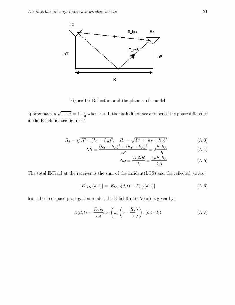
A.2 Two Ray Reflection model:
In this model the two paths from the transmitter, line of sight(LOS) and the ray reflected
from the earths surface(Γ = −1 assuming perfect reflection), interfere with each other at
the receiver. The difference in the distance traveled in the two paths introduces a phase
difference ∆φ = 2π∆Rλ
in the E-field. Using Pythagorean theorem and binomial expansion
Air-interface of high data rate wireless access 31
Figure 15: Reflection and the plane-earth model
approximation√
1 + x = 1+ x2
when x < 1, the path difference and hence the phase difference
in the E-field is: see figure 15
Rd =√
R2 + (hT − hR)2, Rr =√
R2 + (hT + hR)2 (A.3)
∆R =(hT + hR)2 − (hT − hR)2
2R= 2
hT hR
R(A.4)
∆φ =2π∆R
λ=
4πhT hR
λR(A.5)
The total E-Field at the receiver is the sum of the incident(LOS) and the reflected waves:
|ETOT (d, t)| = |ELOS(d, t) + Eref(d, t)| (A.6)
from the free-space propagation model, the E-field(units V/m) is given by:
E(d, t) =E0d0
Rdcos
(
ωc
(
t − Rd
c
))
, (d > d0) (A.7)

Air-interface of high data rate wireless access 32
thus ETOT becomes
ETOT
(
d, t =Rr
c
)
=E0d0
Rdcos
(
ωc
(
Rr − Rd
c
))
− E0d0
Rdcos(0) (A.8)
= −E0d0
Rd(1 − cos(∆φ))) = EdRe 1 − exp(−j∆φ) (A.9)
= |Ed|[
1 + cos2∆φ − 2cos∆φ + sin2∆φ]1/2
(A.10)
= |Ed| [2 − 2cos∆φ]1/2 = 2|Ed|sin(
∆φ
2
)
(A.11)
The relationship between E-field and power received is:
Pr =|ETOT |2Ae
η0where η0 = 120π = 377Ω is the free space impedance (A.12)
Thus Pr = 4|Ed|2Ae
η0
sin2
(
2πhThR
λR
)
(A.13)
The factor |Ed|2Ae
η0
is the power received via the direct path, using the free space propagation
for this direct path and using sinθ ≈ θ for small θ we get:
Pr = 4Pt
(
λ
4πR
)2
GT GRsin2
(
2πhT hR
λR
)
= PtGT GR
(
hT hR
R2
)2
(A.14)
Path Loss(dB) = 40logd − (10logGT + 10logGR + 20loghT + 20loghR) (A.15)
Thus from the two ray model the received power is attenuated by a factor Rn where the
exponent n = 4
A.3 Indoor Propagation: Attenuation Factor Model
The generalized attenuation factor model, falls right off the two ray model:
Path Loss(d)[dB] = PL(d0) + 10nlog
(
d
d0
)
(A.16)

Air-interface of high data rate wireless access 33
the path loss exponent n takes the following values:
Sample path-loss exponents from [10]
Environment n
Free space: 2
Flat rural: 3
Rolling rural: 3.5
Suburban,low rise: 4
Dense urban,skyscrapers: 4.5