Embed Size (px)
Citation preview

39GAir Handling UnitAir flow: 2000 ~ 60000 m³/h

CAT_39G_E-1307_02
CAT_39G_E-1205_01
Jul, 2013
The Manufacturer reserves the right to change any produt specifications without prior notices Version:
Supersede:
Effective Date:

Founded by the inventor of modern air conditioning, Carrier is the world’s
leader in high-technology heating, air-conditioning and refrigeration solutions.
Carrier experts provide sustainable solutions, integrating energy-efficient
products, building controls and energy services for residential, commercial,
retail, transport and food service customers. Carrier is a part of UTC Build
ing & Industrial Systems, a unit of United Technologies Corp., a leading
provider to the aerospace and building systems industries worldwide.
With a broad portfolio of advanced technical patent awards, our global R&D
center in Shanghai develops innovative heat, ventilation and air-conditioning
(HVAC) solutions.
Turn To The Experts
In 1998, Time magazine named Dr. Carrier oneof its 20 most influential builders and titans ofthe 20thcentury.

2
Model Number Nomenclature
Air Flow
Unit Orientation
G
39G
50 =1150mm
50
50
50

3
Double skin panel construction, excellent heat preservation
New sealing material minimizing air leakage
Ingenious condensate drain pan
Hot and cold water coils designed according to international standard
Corrugated damper flexible to adjust
The thickness of PU casing panel is 25mm, with light weight, good rigidity and thermal conductivity coeffi-cient less than 0.0199W/m°C. Moreover, special insula-tion treatment is conducted at the inner parts of the frame and the middle frame strips to prevent the cold bridge effect. The use of high-quality color steel sheet and galvanized steel sheet in the double-skin metal panel ensures good fireproof and rust preventive perfor-mance of the unit.
The unit casing is made up of panels, frame and sealing strips. The panels are connected accurately by adopting unique embedded abutting method. New type of sealing strips between the frame and the panels, and careful sealing design to all access panels and locations passing-through pipes ensure excellent air tightness of the unit, which completely complies with or exceeds the national standard GB/T14294-2008.
This design ensures to drain all the condensed water. The drain valve is arranged at the bottom of the coil return circuit, and this can discharge the seeper and avoid the frost cracking of the coil.
With manual or electric mode available, the corrugated linkage damper can be opened flexibly, and can also add an electric controller as required.
Fins are the "dual sine-wave" form and mechanically bonded with copper tubes, realizing excellent heat transfer efficiency. Hydro-philic aluminum foils may also be utilized to achieve better heat transfer performance. The standard coil header is constructed of steel and can also be customized with copper. Headers have drain and vent connections, so coil is drainable and has non air trapping circuits. The water in the coil must be discharged in winter to avoid the frost crack of the coil.If the coil face air velocity is higher than 2.5m /s, a drift eliminator can be installed on the back of the coil to effectively isolate moisture in air.

4
Belt-driven Fan
High efficiency Filter Bag Filter Panel Filter
Backward Impeller Forward Impeller
Unit base
The fan has the optimized forward or backward double-inletcentrifugal type with low noise and high efficiency.
Various filters available to meet different needs
Modular design convenient to select
Easy maintenance
Each section has a base, which enhances the strength of the whole unit, reduces vibration, and make it easy to transport and assemble.
The fan impeller and pulley are statically and dynamically balanced, and the whole fan is calibrated through the operational vibration testing, making the fan to operate stably and smoothly. With the fan and motor assembly mounted on a common base with shock absorber and the fan outlet isolated from the casing by a flexible connection and completely separated from moving parts, the vibration is effectively isolated. Moreover, the forward or backward impeller may be selected according to the air pressure and volume.
Filters of various filtering levels are available ranging from primary filters (Panel type, efficiency: G4), to medium filters (Bag type, efficiency: F8), and to high filters (H13). And some special filters such as activated carbon filters, cartridge filters and destatic filters can also be provided.
The width, height and length of the unit are proportion-ally increased with 100mm as module. Each air volume corresponds with a certain unit type. Modular products save raw material and control costs to the maximum extent. Standard modular products make modeling and manu-facturing faster and more convenient.
All basic component parts are standard and interchangeable with competitive prices. The unit is designed to have removable panels on its one side, and the access panels are arranged in the necessary components, providing convenience for repair and main-tenance of the fan, coil and filter. The coil is installed on the guide rail inside the drain pan, enabling easy maintenance, cleaning and removal.

Quick Selection
Note:1. The data of 2R coil heating capacity is under the standard condition. (Air temperature in is 15℃ db, water temperature in is 60℃ ) 2. The data of 4R coil cooling capacity is under the standard condition. (Air temperature in is 27℃ db/19.5℃ wb, water temperature in is 7℃ ) 3. The data of 6R coil cooling capacity is under the fresh air condition. (Air temperature in is 35℃ db/28℃ wb, water temperature in is 7℃ ) 4. The unit height does not include the damper on top and the base of 100mm (0608~2333) / 200mm (2532~4750) 5. The cooling and heating capacity of the coil in the table is just for your reference, the data with "*" means temperature difference of in/out is more than 5℃ . Please refer Carrier AHU selection software for detail information.
5
Software
Our company provides the double-quick and accurate computer selection. We will get the reasonable and
Computer Selection
Functions & Features
Project ManagementModular DesignerFree Section Combining
Performance CalculationQuotation
Chinese-English interface
39G
2330 55000 5.81 382.53 333.00 806.95* 772.5 2876*952.5 2350 3050
Unit SizeAir Volume Coil Face
Cooling/Heating Coil Capacity(kW)
Steam Coil Heating
Capacity(kW)
2R Heating 4R Cooling 6R Cooling
InsideDimension
of Damper 39G Dimensions
Hight WidthArea(m²)
6
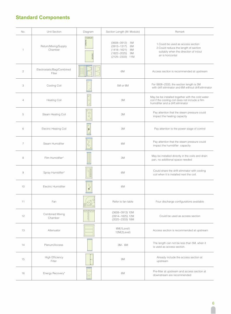
Standard Components
No.
1
2
3
4
5
6
7
8
9
10
11
12
14
15
16
Unit Section
Cooling Coil
Steam Humidifier
Fan
Combined MixingChamber
Plenum/Access
High EfficiencyFilter
Diagram Section Length (M: Module R) emark
Access section is recommended at upstream
May be installed directly in the coils and drain pan, no additional space needed
Four discharge configurations available
May be be installed together with the cold water coil if the cooling coil does not include a film humidifier and a drift eliminator
Refer to fan table
(0608~0912) 5M(0913~1317) 6M(1418~1621) 8M(1822~2025) 9M(2125~2333) 11M
Return/Mixing/Supply Chamber
1.Could be used as access section2.Could reduce the length of section suitably when the direction of in/out air is horizontal
Electrostatic/Bag/Combined Filter
6M
3M、6M
5M or 6M
Heating Coil
Steam Heating Coil
Electric Heating Coil
Film Humidifier*
Spray Humidifier*
Electric Humidifier
Energy Recovery*
(0608~0913) 10M (0914~1825) 12M (2025~2333) 18M
For 0608~2333, the section length is 5M with drift eliminator and 6M without drift eliminator
Pay attention that the steam pressure could impact the heating capacity
Pay attention that the steam pressure could impact the humidifier capacity
Pay attention to the power stage of control
Could share the drift eliminator with cooling coil when it is installed next the coil.
Could be used as access section
The length can not be less than 5M, when it is used as access section.
Already include the access section at upstream
Pre-filter at upstream and access section at downstream are recommended
3M
3M
3M
3M
6M
6M
6M
9M
6M
13 Attenuator Access section is recommended at upstream6M(1Level)
12M(2Level)

7
39G Electric Heating Coil Selection
Filtration Requirement for Clean Rooms
39G2230 4160 5.74 < 114 142 100~225 205 200~335 267
Unit Size
Clean Room Classifications
Clean Room Classifications
Flow Type Turbulence Transition Flow Quasi - laminar Flow
Filter ratio (%)
Coarse
Medium
Fine
Max. Power ofSingle Heater
Face Area Weight Weight WeightPower range of single
row electric heaterPower range of tow- row electric heater
Power range of three- row electric heater
Note: 1. Star connection is used for electric heater wiring. Multiple group control is acceptable with single group capability less than 30kW and power source of 380V/3 phase. 2. Minimum air velocity through the electric heating coil should be 2m/s. 3. When heating capacity can be reach by using 3-row electric heating coils, 3M casing should be used. 4. When heating capacity is more than capacity of 3-row electric heating coils, 6M casing and two electric heating coils are recommended.

8
39G Fan and Motor
39G2330 37 Y225
FC160
FC180
FC180
FC200
FC200
FC225
FC225
FC/BC250
FC/BC250
FC/BC280
FC/BC280
FC/BC315
FC/BC315
FC/BC355
FC/BC355
FC/BC400
FC/BC400
FC/BC450
FC/BC400
FC/BC450
FC/BC450
FC/BC500
FC/BC500
FC/BC560
FC/BC560
FC/BC630
FC/BC560
FC/BC630
FC/BC630
FC/BC710
FC/BC630
FC/BC710
FC/BC710
FC/BC800
FC/BC710
FC/BC800
FC/BC800
FC/BC900
FC/BC800
FC/BC900
FC/BC800
FC/BC900
Unit Size Fan ModelMax. Motor Power Max. Motor Model
Fan section length(mm)Horizontal Vertical
Weight(kg)
Note: Weight in this table is weight of fan and base, which doesn’t include casing and motor weight. Please refer to the selection files for detailed fan motor specifications.
9
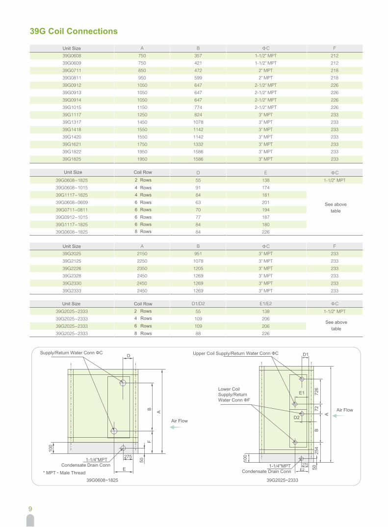
39G Coil Connections
39G2330 2450 1269 3" MPT 233

39G Steam Coil Connections
10
39G2330 2450 884 2" MPT 223 80 150

11
39G Horizontal Unit Air Outlet Arrangements and Flange Dimensions
FC160FC180FC180FC200FC200FC225FC225
FC/BC250FC/BC250FC/BC280FC/BC280FC/BC315FC/BC315FC/BC355FC/BC355FC/BC400FC/BC400FC/BC450FC/BC400FC/BC450FC/BC450FC/BC500FC/BC500FC/BC560FC/BC560FC/BC630FC/BC560FC/BC630FC/BC630FC/BC710FC/BC630FC/BC710FC/BC710FC/BC800FC/BC710FC/BC800FC/BC800FC/BC900FC/BC800FC/BC900FC/BC800FC/BC900
39G2330795.0 1007.0 668 241 150 547767.0 1130.0 754 241 150 604

39G Vertical Unit Air Outlet Arrangements and Flange Dimensions
12
FC160FC180FC180FC200FC200FC225FC225
FC/BC250FC/BC250FC/BC280FC/BC280FC/BC315FC/BC315FC/BC355FC/BC355FC/BC400FC/BC400FC/BC450FC/BC400FC/BC450FC/BC450FC/BC500FC/BC500FC/BC560FC/BC560FC/BC630