Embed Size (px)
Citation preview

Air Hammers

First Steam hammer
made in the US in 1845

Types ofAir/Steam hammers
and extractors
1) Single acting air/steam hammers and extractors2) Differential acting air/steam hammers3) Double acting air/steam hammers

Air/Steam single acting hammers:
Vulcan
The first #1Vulcan was built in 1887
Lifting Sheave
Cylinder
Steam chest
Slide bar
Trip (timing device)
Ram (lump)
Columns
Ram point
Wedges (Cyl, ram ,base)

Vulcan drive caps
Box type
Pipe piles
Drive cap repair items
Concrete & H-beam
Concrete with re-bar
Follower for driving pile into
the groundFor repairing broken cones on top of drive caps

Single-Acting Steam/Air Hammers
Single-acting steam/air hammers are gravity, or drop hammers, for which the hoist line has been replaced by a pressurized fluid –steam or air.
Steam piston
Cylinder
Steam goes in here
Ram
Ram point
Cushion
Drive cap
Pile

Single acting air/steam principle: Vulcan
In single-acting hammers, the motive fluid (air or steam) is working on the upstroke only. The ram falls by gravity on the down stroke. On upstroke, the motive fluid flows under the piston through an open valve. The piston is forced up, lifting the ram to which it is rigidly attached. At the top of the stroke, a valve rotates, blocking the inlet motive fluid path and opening a fluid path to the exhaust port of the hammer. The motive fluid rushes through the exhaust port and the ram falls by gravity. This operation is repeated for each hammer stroke.

Exploded view of singleacting air hammer: Vulcan
Assembled Exploded view

Adding mass to the ram to increase foot pounds of energy
Single actingair/steam:
Vulcan

Single acting air/steam:
Vulcan
Maintenance

Single Acting Air/Steam:
Vulcan
Maintenance

Maintenance
Single Acting Air/Steam:
Vulcan

Vulcan McDermid Basefor Wood piles only

Vulcan Single Acting:
Field Service Manual

Vulcan Single Acting:
Field Service Manual

Vulcan SingleActing:
Field Service Manual

Vulcan Single Acting:
Field Service Manual
Base/cylinder column hole repair

Vulcan Single Acting:
Field Service Manual
Column Repair

McDermid Basefor
2, 1, 106, 06
includingparts detail

Vulcan Single Acting:
Field Service Manual
Outboard bracket shims

Vulcan Single Acting:
Field Service Manual
StudInstallation

Vulcan Single Acting:
Field Service Manual
Assembly procedures and
torquespecifications

Vulcan Single Acting:
Field Service Manual
Piston & rodinstallation

Air/Steam: Vulcan
Safety issues

Differential acting steam/air
hammer

Comparison Single vs Differential
SINGLE ACTING

DifferentialActing
Air/Steam hammer

Heavy ramshort stroke
conceptVulcan

Single Acting Air/Steam Hammer:Vulcan
Lubrication requirements

How do I know how much energy a differential acting hammer is
delivering?

By counting Blows per Minute and referring to an energy chart!

EnergyDelivery: Vulcan

Double Acting Air Hammers

MKT Double-acting Air Hammers•McKiernan-Terry Corp.
The predecessor to MKT was the McKiernan-Terry Company and in 1897 they introducedthe double-acting hammers to the industry.Used to drive steel sheet piling, H-beams,timber piles, and pipe piles their rapid blowsper minute gave the contractor increasedproduction. The MKT double-acting hammerswere also good for underwater driving. Inaddition they can be equipped with moil orchisel points for demolition work.
9B3 10B3 11B3

MKTDouble-actingAir Hammers•Anvils •Attachments

MKT Double-acting Air Hammers
•Operation
In the MKT valve chest air can enter through two passagesat the proper time into the power cylinder. One passageleads to the underside of the Piston and the other passageleads to the topside of the Piston. The valve chest also has aport for exhausting the spent fluid. The Operating Cyclestarts like this – the spool valve opens a path for the airinlet to the underside of the ram and at the same timeopens an exhaust path to the topside of the piston. The ramrises until the upper balancing port is sealed and the lowerbalancing port is open. The pressures on the ends of thespool valve become unequal and the valve is pushed to thedown position. The inlet path is then opened to the topsideof the Piston and the underside of the Piston is open to theexhaust port. The Piston moves down, first closing thelower balancing port, and then opening the upperbalancing port. This action creates an unbalanced pressureat the lower end of the spool valve and the valve is thrownupwards and the operating cycle is repeated.
MKT Double-
acting Air Hammers
• 9B3• 10B3• 11B3
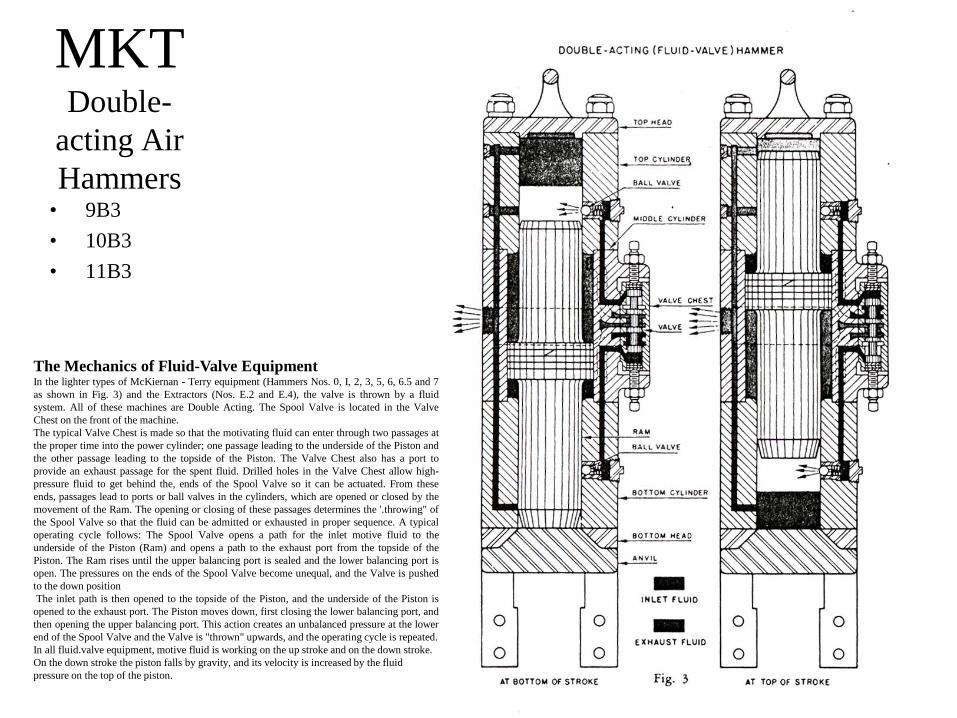
The Mechanics of Fluid-Valve EquipmentIn the lighter types of McKiernan - Terry equipment (Hammers Nos. 0, I, 2, 3, 5, 6, 6.5 and 7as shown in Fig. 3) and the Extractors (Nos. E.2 and E.4), the valve is thrown by a fluidsystem. All of these machines are Double Acting. The Spool Valve is located in the ValveChest on the front of the machine.The typical Valve Chest is made so that the motivating fluid can enter through two passages atthe proper time into the power cylinder; one passage leading to the underside of the Piston andthe other passage leading to the topside of the Piston. The Valve Chest also has a port toprovide an exhaust passage for the spent fluid. Drilled holes in the Valve Chest allow high-pressure fluid to get behind the, ends of the Spool Valve so it can be actuated. From theseends, passages lead to ports or ball valves in the cylinders, which are opened or closed by themovement of the Ram. The opening or closing of these passages determines the '.throwing" ofthe Spool Valve so that the fluid can be admitted or exhausted in proper sequence. A typicaloperating cycle follows: The Spool Valve opens a path for the inlet motive fluid to theunderside of the Piston (Ram) and opens a path to the exhaust port from the topside of thePiston. The Ram rises until the upper balancing port is sealed and the lower balancing port isopen. The pressures on the ends of the Spool Valve become unequal, and the Valve is pushedto the down positionThe inlet path is then opened to the topside of the Piston, and the underside of the Piston is
opened to the exhaust port. The Piston moves down, first closing the lower balancing port, andthen opening the upper balancing port. This action creates an unbalanced pressure at the lowerend of the Spool Valve and the Valve is "thrown" upwards, and the operating cycle is repeated.In all fluid.valve equipment, motive fluid is working on the up stroke and on the down stroke. On the down stroke the piston falls by gravity, and its velocity is increased by the fluid pressure on the top of the piston.

MKTDouble-acting
Extractors•Photographs

MKTDouble-acting
Extractors
•Service & Parts E-2