Embed Size (px)
Citation preview

AFRL-HE-WP-TP-2005-0024
AIR FORCE RESEARCH LABORATORY
Optimal Crash Pulse for Minimization of PeakOccupant Deceleration in Frontal Impact
Zhiqing Cheng
Advanced Information Engineering Services Inc.A General Dynamics Company5200 Springfield Pike, Suite 200
Dayton OH 45432-1289
Joseph A. Pellettiere
Air Force Research Laboratory
October 2005
Interim Report for June 2004 to October 2005
Human Effectiveness DirectorateApproved for public release; distribution is unlimited. Biosciences and Protection Division
Biomechanics Branch
Wright-Patterson AFB OH 45433-7947
- - Form ApprovedREPORT DOCUMENTATION PAGE OMB No. 0704-0188
Public reporting burden for this collection of information is estmated to average 1 hour pe response, including the time for reviewing instructions, searching existing date sources, gathering and maintaining thedata needed, .rd completing and reviewing this collection of information. Send comments regarding this burden estimate or any other aspect of this collection of information, including suggestions for reducingthis burden to Department of Defense, Washington Headquarters Services, Directorate for Information Operations and Reports (0704-0188), 1215 Jefferson Davis Highway, Suite 1204, Arlington, VA 22202-4302, Respoidents should be aware that notwithstanding any other provision of law, no person shall be subject to any penalty for failing to comply with a Collean of information if it does not display a currantlyvalid OMB cntro mber PLEASE 00 NOT RETURN YOUR FORM TO THE ABOVE ADDRESS.
1. REPORT DATE (DD-MM-YYYY) 2. REPORT TYPE 3. DATES COVERED (From - To)
October 2005 Technical Paper - Interim June 2004 to October 20054. TITLE AND SUBTITLE 5a. CONTRACT NUMBER
FAB650-04-D-6472
Optimal Crash Pulse for Minimization of Peak Occupant 5b. GRANTNUMBERDeceleration in Frontal Impact N/A
5c. PROGRAM ELEMENT NUMBER62202F
6. AUTHOR(S) 5d. PROJECT NUMBERZhiqing Cheng (General Dynamics-AIES) 7184
Joseph A. Pellettiere (Air Force Research Laboratory) 5e. TASKNUMBER02
5f. WORK UNIT NUMBER
11
7. PERFORMING ORGANIZATION NAME(S) AND ADDRESS(ES) 8. PERFORMING ORGANIZATION REPORTAND ADDRESS(ES) NUMBERAir Force Materiel Command, Air Force Research LaboratoryHuman Effectiveness DirectorateBiosciences and Protection Division General Dynamics - AIES AFRL-HE-WP-TP-2005-0024Biomechanics Branch 5200 Springfield Pike STE 200Wrigh.•it-Patterson AFB OH 45433-7947 Dayton OH 45432-12899. SPONSORING I MONITORING AGENCY NAME(S) AND ADDRESS(ES) 10. SPONSOR/MONITOR'S ACRONYM(S)
AFRL/HEPA
11. SPONSOR/MONITOR'S REPORT
NUMBER(S)
12. DISTRIBUTION i AVAILABILITY STATEMENT
Approved for public release; distribution is unlimited. Clearance AFRL/WS-05-2722, 1 Dec 05.
13. SUPPLEMENTARY NOTESPublished in the Proceedings of the 2006 SAE World Congress
14. ABSTRACTIn automobile frontal impact, for given restraint characteristics and prescribed impact
speed and crash deformation, what is the optimal vehicle crash pulse that produces the lowestpeak occupant deceleration? In this paper, based on a lumped-parameter model of the occupant-vehicle system, the problem is treated as a best disturbance problem of the optimalprotection from impact. The optimum kinematics of the occupant in frontal impact is found.For linear restraint characteristics, the theoretical optimal crash pulse is obtained, andthe relation of the peak occupant deceleration to the impact speed, crash deformation, andthe vehicle interior rattlespace is established. The optimal crash pulses for passive,active, and pre-acting restraint systems are discussed. Numerical optimization is formulatedto find the optimal crash pulse for general restraint systems. The occupant responses underthe constant-deceleration crash pulse and the half-sine crash pulse are analyzed for linearrestraint systems. Comparisons are made between the optimal crash pulse and these two "non-optimal" crash pulses.15. SUBJECT TERMSWavelets, model validation, biodynamics, modeling, correlation analysis
16. SECURITY CLASSIFICATION OF: 17. LIMITATION 18. NUMBER 19a. NAME OF RESPONSIBLE PERSONOF ABSTRACT OF PAGES Nathan Wright
a. REPORT b. ABSTRACT c. THIS PAGE 19b. TELEPHONE NUMBER (include areaU U U SAR 9 code)
937-255-2554
Standard Form 298 (Rev. 8-98)Prescribed by ANSI Sid. 239.18

06B-207
Optimal Crash Pulse for Minimization of Peak OccupantDeceleration in Frontal Impact
Zhiqing ChengAdvanced Information Engineering Services, A General Dynamics Company
5200 Springfield Pike Suite 200, Dayton, OH 45431-1289
ABSTRACT The study in this paper will take the indirect approachand deal only with the problem in the first step for frontal
In automobile frontal impact, for given restraint impact, i.e., the optimal vehicle crash response. Incharacteristics and prescribed impact speed and crash particular, the issue to be addressed is: in frontal impact,deformation, what is the optimal vehicle crash pulse that for given restraint characteristics and prescribed impactproduces the lowest peak occupant deceleration? In this speed and crash deformation of the vehicle, what is thepaper, based on a lumped-parameter model of the optimal vehicle crash pulse for mitigating occupantoccupant-vehicle system, the problem is treated as a injuries?best disturbance problem of the optimal protection fromimpact. The optimum kinematics of the occupant in A number of studies have been performed on thefrontal impact is found. For linear restraint vehicle crash pulse in the last three decades or so.characteristics, the theoretical optimal crash pulse is Several late studies were particularly concerned with theobtained, and the relation of the peak occupant problem of the optimal crash pulse [1-4]. In [2], baseddeceleration to the impact speed, crash deformation, on a one-mass model and a rigid multi-body model, theand vehicle interior rattlespace is established. The vehicle crash deceleration curve was divided into finiteoptimal crash pulses for passive, active, and pre-acting segments and their effects on the occupant's injury wererestraint systems are discussed. Numerical optimization investigated quantitatively using a sensitivity analysis.is formulated to find the optimal crash pulse for general The optimal deceleration curve for minimizing therestraint systems. The occupant responses under the occupant's injury was obtained by iterative calculations.constant-deceleration crash pulse and the half-sine In [3], based on a two-mass one-dimensional model,crash pulse are analyzed for linear restraint systems. pure rectilinear form is assumed as the ideal pulse forComparisons are made between the optimal crash pulse the occupant deceleration. Three functions were formedand these two "non-optimal" crash pulses. to approximate the rising edge of the rectilinear form
and corresponding initial parts of the vehicle crash pulse
INTRODUCTION were derived. In [1] based on a spring-mass model, theproblem of the optimal crash pulse is addressed by
The structural crashworthiness plays important roles in applying an energy relationship between the vehicle
the prevention and reduction of occupant injuries in crash pulse and the occupant deceleration in a domain
automobile crashes. To attain the optimal of the relative motion between the vehicle and the
crashworthiness of an automobile structure, optimization occupant. It was found that for prescribed impact
is an effective tool and becomes a common practice in velocity and vehicle crash deformation, the optimal
the vehicle design. Optimization can now be conducted pulse is one that consists of an impulse, a subsequent
in a virtual environment based on computational zero-acceleration period, and finally a constant level
modeling, simulation, and analysis of a system. period. In [4], the problem was also described by a one-mass model, the crash pulse was discretized with
The optimization problem of the vehicle crashworthiness respect to the crash deformation, and a solution
can be dealt with analytically with two approaches, direct procedure using numerical optimization was proposed to
and indirect [1]. The direct approach uses physical find the optimal crash pulse.
parameters of the vehicle structure as the designvariables in optimization. The indirect approach handles In this paper, the problem of the optimal vehicle crashthe issue by a two-step strategy: first, for the pulse is treated as a best disturbance problem ofminimization of the occupant injuries, find the optimal optimal protection from impact.response for the vehicle structure; then, solve aninverse design problem for the vehicle structure SYSTEM MODELING AND PROBLEMaccording to its optimal response or use the optimal STATEMENTresponse as a guideline for the vehicle structure design.
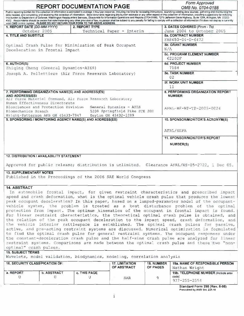
The models used for computational modeling of with the initial conditionsautomobile crashworthiness can be classified as x(0) =0, .*(O) v0 , (5)lumped-parameter models, rigid multi-body (RMB) andmodels, finite element (FE) models, and integratedmodels [5]. These models provide different levels of Y( 0 ) = 0, A(O) 0, (6)
abstraction of the problem, and thus have different where vo is the impact velocity.applications. In frontal impact, the occupant can besubject to injuries to various regions of the body, such The question to be addressed in this paper can beas the head, thorax, upper extremities, and lower expressed as:extremities. The injury criteria for measuring theseinjuries are usually expressed by impact responses Problem-I: For given restraint characteristics and(such as accelerations) in respective regions. When the prescribed impact velocity and crash deformation, findprevention and reduction of injuries to the occupant are the optimal crash pulse such that the peak occupantconsidered in general, the occupant can be reasonably deceleration is minimized. The problem can betreated as a point mass and its peak acceleration decelated as Find the proble cash(deceleration) can be used as the injury criterion. When formulated as: Find the optimal vehicle crashthe vehicle crash pulse is under investigation, the pulse ao(t), such thatvehicle is treated as a whole body and only its gross J,(a,, Minn{J,(a) 1 .12(a) < D, J 3 (a) S0o (7)motion is considered. '
whereTherefore, automobile frontal impact is described by a max{-[k(t)j+ i(t)]), (8)lumped-parameter model shown in Fig. 1, where the toccupant is represented by a point mass m, the peak occupant deceleration,x(t) describes the gross motion of the vehicle, and y(t) J2 = max{x(t)}, (9)t
is the motion of the occupant relative to the vehicle. The the maximum vehicle displacement, andinteraction between the occupant and restraint systemJ m, (10)such as seat belt and airbag, is simply represented by a J3 mtax~ythspring and a damper, but, in general, it can be described the maximum forward excursion of the occupant in theby a control force u(yj.',t). For the vehicle motion, vehicle.a(t) = -Y(t), (1) From the standpoint of the kinematics of the occupant,usually referred to as the vehicle crash pulse, and Problem-i can be reduced to a more generic problem:Dý = max{x(f)), (2)
defined as the vehicle crash deformation. The free Problem-2: For prescribed impact velocity, crash
space between the occupant and the vehicle interior is deformation, and rattlespace, find the optimalkinematics of the occupant such that the peak occupant
called the rattlespace So., which is the maximum deceleration is minimized while the maximum occupant
allowable space for the occupant to move forward with forward displacement is bounded. The problem can berespect to the vehicle, i.e., formulated as: Find the optimal kinematics of themax{y(Q)} •< S0 . (3) occupant wo(t), such that
t
Since this space has important effects on the occupant J, (wo) min {J, (w) IJ 4 (w) < DO}, (11)response also and is a major factor in the restraint
system design, it will be considered in addition to the wherecrash deformation. J4 =max {x(t) + y(t))}, (12)
___SO_ +1 which is the maximum forward displacement of the
D . k occupant, and
Do = +So , (13)the allowable maximum forward excursion for theoccupant in an inertial frame. Note that, unlike a(t) in
Problem-I, w(t)is not a control function of the system.
Instead, it is controlled or produced by a(t) or
u(y,t) .
Figure 1. A lumped-parameter model of the systemOPTIMAL OCCUPANT KINEMATICS
The equation of motion of the system ism(k++Y)+u(y,.t) =0, (4) To find the optimal kinematics of the occupant for
Problem-2, according to duality or reciprocity of2

optimization [6], the dual or reciprocal problem of This is the optimal kinematics of the occupant forProblem-2 can be formulated as follows. Problem-3.
Problem-3: For prescribed impact velocity, vehicle Based on the duality or reciprocity between Problem-2crash deformation, and rattlespace, find the optimal and Problem-3, the optimal kinematics of the occupantkinematics of the occupant such that the maximum for Problem-2 can be stated as: In order to minimize theoccupant displacement is minimized while the peak peak deceleration of the occupant, the deceleration ofoccupant deceleration is bounded. The problem can be the occupant should remain constant at a value, whichformulated as: Find the optimal kinematics of the is denoted as Am and is given by
occupant wo(t), such that 2= Vv0 /(2Do). (23)
J, (wo )min {J 4 (w) I J, (w) < Am,} (14)
where A is the upper bound on the peak occupant This is also the optimal kinematics of the occupant formh Problem-l.
deceleration.THEORETICAL SOLUTION OF OPTIMAL CRASH
To find the theoretical solution of Problem-3, denote
z(t) x(t) + y(t), (15) PULSE
which is the absolute motion of the occupant with Linear Restraint Characteristicsrespect to an inertial frame during impact. Consider themotion of the system from the initial of impact t = 0 to Optimal Crash Pulse
the instant t - T. when the occupant comes to a rest for Suppose the onset of the vehicle impact is at t = 0.
the first time. That is, Consider the motion of the occupant right after the onseto[+ i(t)d 0 (16) of impact (I = 0- ) until a stop for the first time (t = To).Vo + Z-~- .(6
As the initial conditions of the occupant are
The velocity of the occupant i(t) starts with v0 at t = 0 z(O) = 0, 2(0') = v 0 , (24)
and decreases to 0 at I = To , i.e., the optimal kinematics of the occupant is
i(t) > O, 0:< t•< o. (17) (t) = -A
Therefore, forO t <_ To, the displacement of the 20) = v, - At, 0' 5 t 7 To, (25)
occupant z(t) , which is given by z(t) = vot - I At 2
z(t) = (z-)d-r, (18) where A, is yet to be determined. From Eq. (4)
increases monotonically with respect to time and u(y, j', t)= mA,,. (26)
reaches its maximum value at t = To , that is, Suppose the characteristics of a restraint system can beexpressed by a linear spring and a linear damper. That
max{z(t)) = z(To). (19) is,
To minimize the maximum occupant forward u(y,j',t) 0 = y+c+. (27)
displacement J,I Then,
,J4 Z maxfx(t) +y(t)) = max {z(t)) = z(To), (20) ky+cmA, (28)t t4O.To] with initial conditions
T. should be minimized. According to the definition of y(O+) = 0, j.(0+) = 0. (29)
To (Eq. (16)), if the deceleration of the occupant - (t) The solution of Eq. (28) is
takes the maximum allowable value Am , that is, mA, -ki
40 = -A (21) yQ) = (1-e 0 ).1 ' k
To is minimized, and in -tT((t) = m e c , 0k _t_ o. (30)7; - --v0 (22) C
A.m kmA.This means that in order to minimize the peak CJ) 2 e
displacement of the occupant, the deceleration of the From Eqs. (15) and (25), the optimal motion of theoccupant should remain constant at the value of A,. vehicle can be expressed as
3
km--_k twhere the exponential term is neglected. Then,k(t) -Am.(I -e ), (31a) s =mA. _ A., (40)
i(t)=v -_AmtQ+_e T ), 0, <t<_TO, (31b) where-'k -A 2 -=k (41)
XQ vt-IAt2 _mAm (Il-e c,) (31 c) mx(t) =Vo t k which can be considered as the natural frequency of the
It follows that restraint-occupant system. From Eqs. (38) and (40)2
x(0+) = 0, k(O t) = vo - Am/c. (32) 0_2 V0 (42)
Compare to Eq. (5), from t = 0 to 1 0 the velocity 2So (DI + So)(
change of the vehicle is which represents a requirement for the restraintcharacteristics. This means that when the natural
Av x(O) - x(0' -A,. (33) frequency of the restraint-occupant system satisfies Eq.c (42), the rattlespace S0 will be fully used for the
To produce this velocity change, the acceleration of the occupant's excursion with respect to the vehicle.
vehicle needs to have an impulse I. at the initial of In general, however, restraint systems are designed
impact (t =0). Theoretically, this impulse can be such that
represented by a Dirac delta function 5(t); that is, max{y(t)) < S. (43)t
Aom m (34) i.e., the rattlespace is not fully used. In this case,, itc follows from Eqs. (23) and (31c) that
where 5(1) is given by max{x(t)}=x(T) v° mA D
, t 0 (32Am)k,(4i(t)= °0 , (35) where the exponential term in Eq. (31c) is neglected
0, t0also. From Eq. (44),and
1fi(t)dt = 1. (36) A W,: kD 2mvo_oo2m( 1± -.D 1)
_W 2m k2As such, from the onset of impact (1 0) to the first (45)
stop (I = To), the optimal vehicle acceleration is C- ) D, 2v2km--- ( 1 1(D2 2
At) -A [+ 5 (t) k m e 0 < t < To (37)c ()- - - • which indicates that the peak occupant deceleration or
the amplitude of constant deceleration depends uponSince impulse IQ(t) results in only velocity change but the impact speed, vehicle crash deformation, and the
no displacement change of the vehicle, Eq. (31c) still natural frequency of the restraint-occupant system.
holds for 0 < t < 70. According to Eqs. (30) and (45), Eq. (43) means that2
Note that the exponential terms in Eqs. (30), (31), and O)2 > vo (46)(37) diminish with time. After a sufficiently long time 2So (D +SO)they can be neglected. which represents a requirement for the restraint
characteristics such that the rattlespace is not fully used.Determination of Am It can be inferred that if
If restraint characteristics are such that the maximum 22 v2forward excursion of the occupant relative to the vehicle 0< (47)reaches the prescribed rattlespace, in other words, if the 2So (D + SO)rattlespace is fully used, according to Eq. (23), the excursion of the occupant will exceed the space
S2 limit. This is a situation not allowed to happen.A. =- v (38)
2(D, + SO ) Illustration of Optimal Crash PulseIt follows from Eq. (31c) that From Eq. (37), the optimal crash pulse can bemax{Y(t) = x(T) D, +So -mA -D, (39) expressed as
k4

Amt_ A km ek that as the rattlespace S, increases, the peak occupantA(t)= A,[Ic) e deceleration A. decreases.
Blue-vehicle Red-occuparyt Green-relativeA [1 + (0- -t7l ], 0 To 00
2~w 0 0 -
(48)where ,
"6-1000 ,--C C 0 0 0.02 0.04 0.00 0.08 0.1 0.12
-2on 2km (49) < Time (s)
which is referred to as the damping ratio of the restraint-occupant system. Introducing o) and 4 reduces the 10
C.)
parameters in Eq. (48) and avoids providing a value for 2 "-_-_------.--__m , which varies from occupant to occupant. > 0 0.02 004 0.06 0.08 0.1 0.12
Time (s)EýFor the illustration of the optimal crash pulse, choose _ .the values for the parameters in Eqs. (45) and (48) to be
EIrepresentative of automobile frontal impact [1]: .
v. =-15.56 m/s (35 mph), D. =0.71 m (28 in), C- .
W) = 42.43 rad/s, and = 0.20. The optimal crash Time (s)pulse together with the velocity and displacement of thevehicle and the optimal kinematics of the occupant are Figure 2. The motions of the vehicle and the occupantillustrated in Fig. 2. Note that the impulse of the deltafunction at I= 0 should lead the deceleration of the 4 5
Blue-Optimal Pulse
vehicle at t = 0 to go infinite, but in the figure only a 00 Green-COnstant Decelers o
finite large value can be displayed. After I= 0, the 350 Red-Hatf-sne Pulse
acceleration of the vehicle jumps to a large positive Evalue and then decays, and, after a certain period of - 300
time, it basically remains constant at a negative value. 250E 250-
With this optimal crash pulse, the deceleration of the -1occupant remains constant during impact. After a 200o
certain time, the relative acceleration and velocitybetween the occupant and the vehicle become zero, and 150
the relative displacement between them remains 100 o.o o ' 02 0.25 03 o.5 0.4
constant. Rattlespace (m)
Trade-off Curve Am v. Figure 3. The relationship between the peak occupant- A S. deceleration and the rattlespace
For a prescribed optimal crash pulse (vo and D, aregiven), if the natural frequency of a restraint systemmeets the requirement of Eq. (42), the given rattlespace In general, the characteristics of restraint systems canSo will be fully used and then the peak occupant be so complicated that they cannot be reasonablydeceleration will be minimized. For the restraint system described by a linear spring and a linear damper.design, So is an important factor and can be used as a However, regardless of the complexity of restraint
characteristics, once they are given, the relative motioncommon basis for the comparison of various designst of the occupant with respect to the vehicle can beThe relationship between the minimum peak occupant determined by solving Eq. (26), and then the optimaldeceleration A,, and the prescribed rattlespace So can motion including the optimal crash pulse of the vehiclebe expressed in the form of a so-called trade-off curve, can be obtained. Whereas the optimal crash pulseAccording to Eq. (38), the relationship between the peak depends upon the characteristics of particular restraintoccupant deceleration A, and the rattlespace S. is systems, certain general aspects of it can be
ascertained based on the preceding analyses andshown in Fig. 3 by the blue curve for a range of S. results.
v= 15,56 and D= 0.71. The curve indicates If restraint systems are passive and have certaindamping, an impulse is required at the initial of the
optimal crash pulse.
5

" If restraint systems are active and able to generate where AL and AU are the lower and upper bounds onan impulsive action on the occupant actively, aninitial impulsve maytn onothe rqui nthe optimaly, athe crash pulse. A nonlinear optimization method can beinitial impulse may not be required for the optimal used to solve this problem [7].crash pulse.
" The major portion of the optimal crash pulse afteran initial period tends to be flattened. OTHER CRASH PULSES
NUMERICAL SOLUTION OF OPTIMAL CRASH The optimal crash pulse given by Eq. (48) is meaningful
PULSE only in a theoretical sense, since the initial impulse,which is represented by 3(t), cannot be produced in
When restraint characteristics are nonlinear, or when practice. To be more practical, the vehicle decelerationrestraint characteristics are linear but the motion of the during impact can be assumed to remain constant; thatvehicle is subject to other constraints such as a limit on is, the crash pulse is a constant-deceleration pulse.the amplitude of the deceleration, the optimal crash More often, the vehicle deceleration in frontal impact ispulse cannot be readily obtained analytically. Instead, represented by a half-sine pulse. What are the occupantnumerical optimization can be utilized to find solutions. responses under these two "non-optimal" crash pulses?
The issue will be investigated in the following analyses.In order to use numerical optimization methods to solve Again, a restraint system is assumed to have linear
Problem-I, discretize the time interval [0,T 0] into characteristics, as described by Eq. (27).
identical subintervals. In addition, represent the crash It can be reasonably assumed that the peak occupantpulse a(t) on each of the subintervals by a constant deceleration occurs within the duration of the vehicle
value, that is, crash pulse. Therefore, the occupant responses will beconsidered within the time span of the crash pulse in the
a(t)=ai for (1-i)At<_t<iAt,i=1,...,N, [50] following analyses. In the following computations,choose impact velocity v0 =15.56 m/s and crash
where N is the number of subintervals, At is the length deformation D, = 0.71 m, to be representative ofof each subinterval, and At = ToIN. Denote automobile frontal impact [1].
A = [ala2...aN, f [51] Constant Deceleration Pulse
Suppose the vehicle deceleration is constant, that is,as the vector of design variables. The motion of the x(t) =-.4, 0 <•t< Tv (57)
occupant relative to the vehicle is discretized -= '
accordingly where2
y1=~~t,~ =5it)i1..,,[52] -v 2D (8
andand can be obtained from the numerical integration of 2D,Eq. (4). The system performance criteria of Eqs. (8) - T = -, (59)(10) can be expressed by the discretized system Voresponses: where Tv is the duration of the crash pulse. The velocity
.'1 (A) = mx{-(i; + 51),), (53) and displacement of the vehicle are
J 2 (A) = max {x,, (54) -(t) vo - Avt (60)and
and 1J-4 (A) = max{y, }. (55) x(t) vot -2-At, (61)
From Eq. (28), the equation of motion of the occupantThen Problem-1 can be formulated as a numerical with respect to the vehicle isoptimization problem: Y± + 24- o., + W2y = A'' (62)Design Variables-, A ;with initial conditionsObjective t'1unction: mmi{ J• (A) }; (56) y(O) =0, 0(O) = 0. (63)
Constraints: J2(A) _< D By solving this equation, the motion of the occupant
J3 (A) < So; relative to the vehicle is given by
AL • A <_ AU y(t) = y (t) + y, (t). (64)
Here,6
Se cos( _2 tproduced by a constant-deceleration pulse is muchy, W) = W[1 /l-- -2 (1-4" got-ay)], (65) larger than that resulting from the optimal crash pulse.
)2 The comparison of the peak occupant decelerations
where between the optimal crash pulse and the constantdeceleration pulse is shown in Table 2 for a series of
ay = tan-i ( ), (66) specific rattlespaces.
- 200 Blue-Occupart Red-Relative Green-Vehitce
and 0 0
yC(,) = A oe - - 13,/7- + 8Y) . (67) 0. 03 T . me.s
where < o 001 002 .0o3 0.04 o.06 0. 0 7 0.08 0.09 0.1
I 2 2 Time (s)A,; = Cly + C2Yl__ + 2•'CjyC=, (68) 20 -1
and t a -10]_VI 2 ,>" o 0.01 0.02 0.03 0.04 0.05 U6• 0,07 0.09 0'o9 0.1
fly tan- '2 + y, (69) Time (s)
In Eq. (68), is g by Eq. (
Cly 2 Y( _ . COS -- O M00 0.02 0.03 0 3340.05 o.76 0O 0,8 0.2 0 .1
(70) Tm s
The ocpsin t cosray) Figure 4. The motions of a system under a constant-) Ioodeceleration pulse
The absolute motion of the occupant is the superposptionof the vehicle motion and the relative motion: Table 1. Optimization results for a constant decelerationZ W) = x(W + yW ), (71) )ulse MS) o(M
where x(t) is given by Eq. (61) and y(t) by Eq. (64). lo (rad/s) A.0.01 34.63 335.76 0.280
The occupant responses under a constant-dece lesration 0.10 34.83 297.37 .0243
pulse are illustrated in Fig. 4, where fq=35.43 and 0.20 35.43 267.99 0.207
d=0.2. It is shown that the occupant deceleration corresponding0.40 38.10 232.48 0.1471
during impact is not constant, which means that the 0.50 40.60 221.38 0.120optimal kwnematics of the occupant is not attained. In 0.60 44.61 212.93 2.294fact, under a constant-deceleration crash pulse, it is 0.70 52.73 206.35 0.064impossible for a passive restraint system to provide the 0.120 14.39 204.77 0.048required protection to the occupant such that the optimalkinematics of the occupant is apieved [8]. However, Table 2. Comparison of peak occupant decelerationsthe restraint characteristics of a passive system can still between o imal pulse and constant-deceleration pulsebe optimized to minimize the peak occupant 041 3 2deceleration as much as possible. Table 1 provides the 0,,2, (33s25 A,7 A,,1 .values of the required rattlespace, optimal frequency, a nd (Optimal (Constant pand minimal peak occupant deceleration corresponding PulsDecelerationto each level of damping for a linear passive restraint Pus))x100%system, which were obtained from numerical 0.048 159.71 204.77 28.2optimization [8]. 0.064 156.40 206.35 31.9
0.094 150.57 212.93 41.4Based on the results given in Table 1,.the relationship 0.120 145.85 221.38 51.8between the peak occupant deceleration and the 0.147 141.26 232.48 64.6rattlespace is displayed in Fig. 3 by the green curve. 0.176 136.63 247.39 81.1The curve indicates that the peak occupant deceleration 0.207 132.01 267.99 103.0increases with the increase of the rattlespace, which 0.243 127.03 297.37 134.1seems not logical. The consequence is due to the 0.280 122.28 357 7.damping. In the range of [0.01 0.728], larger damping 357 7.
results in smaller required rattlespace and lower peak Half-sine Pulseoccupant deceleration. However, as shown in Fig. 3, fora given rattlespace, the peak occupant deceleration
7

Suppose the vehicle acceleration is described by a half-sine C2 )2 +C2 ±2CCrwpulse, .Z 2z ( -'2)o - , (83)
Y(t) = -A, sin(-), 0•< t!_ T,, (72)T11, and
where c- 1C4] ago
2 7tan3(- (84)A, = 0-__ (73) ClzCgo + C2,
4D, where
and T, is given in Eq. (59). The velocity and 1 ( )2 ,Codisplacement of the vehicle are C,- Ak go sin(a, -q)
(+ Cos- (74) _ )2 2 +(2gov )2
12f Tv ' ) (a)
and Ivo T , . 2t A -Co Cos
x(t) sm . v 0 Ag cos(a. )2 7C" 2 • 2 0)2 [1_(%21]2 +(2;wvo)2
It follows from Eqs. (4), (15), and (27) that W W
Y + 2;i- + gz 1"- (2" co + go2t) + In Eqs. (82) and (85), (85)
2 o I +0 2 (76) qp=tan-' 24wav (86)
[4T2 cocos-- sin- 7c
Denote The occupant responses under a half-sine pulse are- illustrated in Fig. 5, where co = 32.78 and " 0.2.v (77) Again, the optimal kinematics of the occupant is not
and attained. In fact, under a half-sine crash pulse, it is alsoimpossible for a passive restraint system to provide the
t (2 V) (78) required protection to the occupant such that the optimala tan- 1 (8ao kinematics of the occupant is achieved [8]. However,
Then, Eq. (76) becomes the restraint characteristics can still be optimized tominimize the peak occupant deceleration as much as
Y + 24)w± + o± z = -v -(2,-)o+ Co21)+ possible. Using numerical optimization [8], for a number2 of levels of damping, the values of the required
co2A/ (79) rattlespace, optimal frequency, and the corresponding
2 1 + (2ý"o)2 sin(o, t + az) minimum peak occupant deceleration are listed in Table3.
Blue-Occupant Red-Relatie Gre en-Vehicle
By solving this equation, the motion of the occupant 200. -
under a half-sine pulse is found to be: E 20
ZQ) = (80) 6
where < 0 0.01 0.02 003 0,04 0-0 0.6 0.07 0.08 0.09 07
Time (s)
z,(t)= Z.e- sin(1 -,;,ot +,fl'), (81) -20
and ~10V~0 0
Z (t) 0 t + > 0 o.01 0.02 0.03 0.04 0-06 006 007 08 009 02 Time (s)
S+ 2. (82) E . .
I sin(a ,,t+ a ) 0 o0-V2 0 0. 0,2 0.0 3 .04 0 01 0.08 0.07 0.08 009- 01
a) Co Time (s)
In Eq. (81),Figure 5. The motions of a system under a half-sine
pulse
8
Based on the results given in Table 3, the relationship after that, it jumps to a large positive value and thenbetween the peak occupant deceleration and the decays; and after a certain period of time, it basicallyrattlespace is displayed in Fig. 3 by the red curve. The remains constant at a negative value. In general, thecurve indicates that the peak occupant deceleration optimal crash pulse depends upon the characteristics ofincreases with the increase of the rattlespace, because particular restraint systems.the damping is controlled at each level. In the range of[0.01 0.99], larger damping results in smaller required Different crash pulses have different influences on therattlespace and lower peak occupant deceleration. It can occupant motion and the restraint system design. Forbe seen from Fig. 3 among the three crash pulses linear restraint characteristics, the peak occupantconsidered, the optimal crash pulse is the best, followed deceleration resulting from the optimal crash pulse isby the constant-deceleration pulse, whereas the half- much lower than those produced by a constant-sine pulse is the worst, in terms of the resulting peak deceleration pulse or a half-sine pulse. Under theoccupant deceleration. The comparison of the peak optimal crash pulse, the peak deceleration isoccupant decelerations between the optimal crash pulse independent of the damping of restraint systems.and the half-sine pulse is shown in Table 4 for a series However, certain damping in the systems is necessary,of specific rattlespaces. and large damping can reduce the amplitude of the
initial impulse. Under a constant-deceleration pulse or aTable 3. Optimization results for half-sine pulse half-sine pulse, the damping of restraint characteristics
4 w (rad/s) A. (Mis 2) So (M) is important and determines the required rattlespace and0.01 34.5 41476 0348natural frequency. In a certain range of the damping, the
0.01 34.51 414.76 0.348 peak occupant deceleration decreases with the increase0.10 33.62 365.16 0.317 of the damping.0.20 32.78 331.12 0.289
0.30 32.06 310.20 0.265 It is recognized that the use of a lumped-parameter0.40 31.44 297.02 0.245 model for the occupant-vehicle system and the0.50 30.91 288.46 0.228 assumption of linear characteristics for restraint systems0.60 30.44 282.75 0.213 may have imposed certain limitations on the analyses in0.70 30.04 278.87 0.20 this paper. However, the results and conclusions derived0.80 29.68 276.18 0.188 can still be used as general guidelines for the0.90 29.37 274.24 0.178 crashworthiness design of the vehicle structure.0.99 29.11 272.96 0.169
REFERENCESTable 4. Comparison of peak occupant decelerations
between optimal pulse and half-sin pulse 1. Shi, Yibing, Wu, Jianping, and Nusholtz, Guy S., Optimal
A,,o (mVs2 (m/s 2 AM -1 Frontal Vehicle Crash Pulses-A Numerical Methods forA,,. (is) m Design, EMV, 2002.
(Optimal (Half-sine Amo 2. Takahashi, K., Suzuki, Y., Komamura, T., Suzuki, T.,Pulse) Pulse) x1 00% Awarayama, T., and Dokko, Y., Optimization of Vehicle
Deceleration Curves for Occupant Injury, SAE paper0.169 137.72 272.96 98.2 9307515, 1993.0.178 136.33 274.24 101.2 3. Motozawa, Y. and Kamei, T., A New Concept for0.188 134.81 276.18 104.9 Occupant Deceleration Control in a Crash, SAE paper
0.20 133.03 278.87 109.6 2000-01-0881, 2001.0.213 131.16 282.75 115.6 4. Wu, J., Nusholtz, G.S., and Bilkhu, S., Optimization ofVehicle Crash Pulse in Relative Displacement Domain,0.228 129.06 288.46 123.5 International Journal of Crashworthiness, Vol. 7 No. 4,0.245 126.76 297.02 134.3 397-413, 2002.0.265 124.16 310.20 149.8 5. Cheng, Z.Q., Pilkey, W.D., Pellettiere, J.A., and Rizer,0.289 121,18 331.12 173.3 A.L., Limiting Performance Analysis of Biomechanical0.317 117.87 365.16 209.8 Systems for Optimal Injury Control, Part One-Theory0.348 114.42 414.76 262.5 and Methodology, International Journal of
Crashworthiness, to appear in 2005.6. E. Sevin and W.D. Pilkey, Optimum Shock and Vibration
CONCLUDING REMARKS Isolation, Shock and Vibration Information AnalysisCenter, Washington D.C., 1971.
In automobile frontal impact, the optimal kinematics of 7. Balandin, D.V., Bolotnik, N.N., and Pilkey, W.D., Optimalthe occupant is such that the occupant moves at a Protection From Impact. Shock, and Vibration, Gordonconstant deceleration. For given restraint and Breach Science Publishers, Amsterdam, Thecharacteristics, it is possible for the occupant to attain Netherlands, 2001.optimal kinematics by optimizing the vehicle motion or 8. Zhiqing Cheng, and Joseph A. Pellettiere, Optimalthe vehicle crash pulse. For linear restraint Restraint Characteristics for Minimization of Peakcharacteristics, the optimal vehicle acceleration should Occupant Deceleration in Frontal Impact. Submitted tohave a large negative impulse at the initial of impact; 2006 SAE World Congress.
9


![Development of Mathematical Models for Analysis of a ... · covered in [9]. To perform analysis of the crash event one can use wavelet – based approximation of the crash pulse:](https://img.dokumen.tips/doc/110x75/5f04264a7e708231d40c8e61/development-of-mathematical-models-for-analysis-of-a-covered-in-9-to-perform.jpg)


![OPTIMAL PULSE SHAPES FOR PERIODIC REVERSE …sina.sharif.edu/~khorasani/Publications/21.pdf · plating of alloys [1-3], thin films [4], and even decorative coatings [5]. In the pulse-plating,](https://img.dokumen.tips/doc/110x75/5a7fb2ce7f8b9a9d308babdb/optimal-pulse-shapes-for-periodic-reverse-sina-khorasanipublications21pdfplating.jpg)


![Optimal occupant kinematics and crash pulse ...the problem, Wu et al. [4] discretized the crash pulse with respect to the crash deformation and then implemented numerical optimization](https://img.dokumen.tips/doc/110x75/6134ce94dfd10f4dd73bf7a2/optimal-occupant-kinematics-and-crash-pulse-the-problem-wu-et-al-4-discretized.jpg)