Embed Size (px)
Citation preview

Page 1 unrestricted
Air Core Reactors:Magnetic Clearances, Electrical Connection,
and Grounding of their Supports
David CaverlyKlaus PointnerRoss Presta
Minnesota Power Systems ConferenceNovember 2017
Peter GrieblerHelmut ReisingerOtto Haslehner

Page 2 unrestricted
Voltages:600 V to 1000 kV (Series)600 V to 500 kV (Shunt)
Power:5 kVAr to 600 MVAr(60 Hz Equivalent)
Inductance:0.01 mH to 10 H
Current:6000 -8000 Amp for“normal” applications
up to 320 kApeak
Dry Type Air Core ReactorsApplications
for TransmissionSystems
up to765 kV
Current Limiting & PowerFlow Control Reactors
up to500 kV,and150 MVAr/3 phase
Shunt Reactors
Filter Reactors
Current LimitingReactors
Capacitor (Damping)Reactors
HVDC Reactors
Electric Arc FurnaceReactors
Test Reactors
up to100 MVAr /Phase
HVDC SmoothingReactorsup to 800 kV,600 MVAr(incl. seismicdesign)
Note:
Modern Dry Type Air CoreReactors are Custom Designed tothe application. There are no“standard” ratings.
up to4000 A
forDistributionSystems
built according to specificcustomer’srequirements
Thyristor ControlledShunt Reactors

Page 3 unrestricted
Dry Type Air Core Reactor Construction:
Page 4 unrestricted
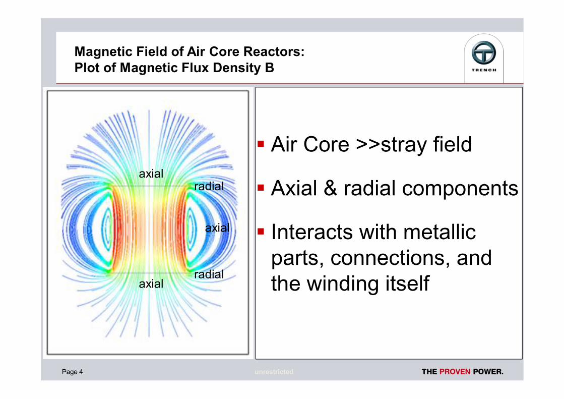
Magnetic Field of Air Core Reactors:Plot of Magnetic Flux Density B
ƒ Air Core >>stray field
ƒ Axial & radial components
ƒ Interacts with metallicparts, connections, andthe winding itself
axial
axial
radial
axial
axial
axial
axial
radial
radial

Page 5 unrestricted
Magnetic Field of Air Core Reactors:Magnitude Contours of Flux Density B
ƒAt the reactormid-plane:
ƒ field strengthdrops off as theinverse of thecube of thedistance r
Reactormid-plane
418A, 114.23 ohm @ 60Hz, 20 Mvar
50 mT5 mT

Page 6 unrestricted
Magnetic Field of Air Core Reactors:Implications of Stray Magnetic Field
Implications of Stray Field:
ƒ eddy currents & lossesin conducting parts
ƒ Induced currents, lossesand forces in closedloops
ƒ forces on current carryingconductors
axial
axial
radial
axial
axial
axial
axial
radial
radial

Page 7 unrestricted
Implications of Stray Magnetic FieldEddy Currents
B
I eddy
Radial FieldEddy Currents
B
I eddy
Axial FieldEddy Currents
Connectors
Insulator Caps
Eddy currents are in inducedin all conducting parts in thereactor stray magnetic field

Page 8 unrestricted
Implications of Stray Magnetic FieldEddy Current Losses
Eddy Current Loss estimation
ƒ
ƒ
ƒ which can be re-arranged as:
,
Loss dependenceapproaches the cube
of the thickness(depending on )φ
W/m

Page 9 unrestricted
Implications of Stray Magnetic FieldEddy Current Losses
Key take Aways:ƒ eddy losses (P) are strongly
dependent on the thicknessof the profile normal to thefield (d)
… and also …ƒ 2BP×
Note : eddy loss calculations are normally doneusing FE methods
Page 10 unrestricted
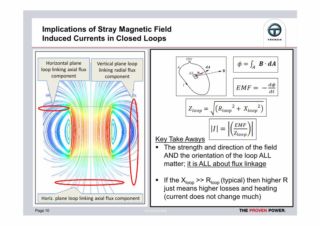
Implications of Stray Magnetic FieldInduced Currents in Closed Loops
Key Take Awaysƒ The strength and direction of the field
AND the orientation of the loop ALLmatter; it is ALL about flux linkage
ƒ If the Xloop >> Rloop (typical) then higher Rjust means higher losses and heating(current does not change much)
Horizontal planeloop linking axial flux
component
Horiz. plane loop linking axial flux component
Vertical plane looplinking radial flux
component

Page 11 unrestricted
Implications of Stray Magnetic FieldElectrodynamic Forces
ƒ Lorentz Force Lawƒ “Right Hand Rule”ƒ = ƒ = ∅ƒ (t) is oscillatoryƒ direction is lateral to
spider/terminalƒ to minimize force :
minimize ∅
∅

Page 12 unrestricted
Practical Implications of the Theory:Magnetic Clearance Guidelines
ƒ MC1: Clearance to smallmetallic parts not formingclosed loops
ƒ MC2: Clearance to largemetallic parts or partsforming closed loops
ƒ Clearances are shown ondrawings (based on fieldstrengths)
ƒ OD/2 & OD: roughapproximations
Page 13 unrestricted
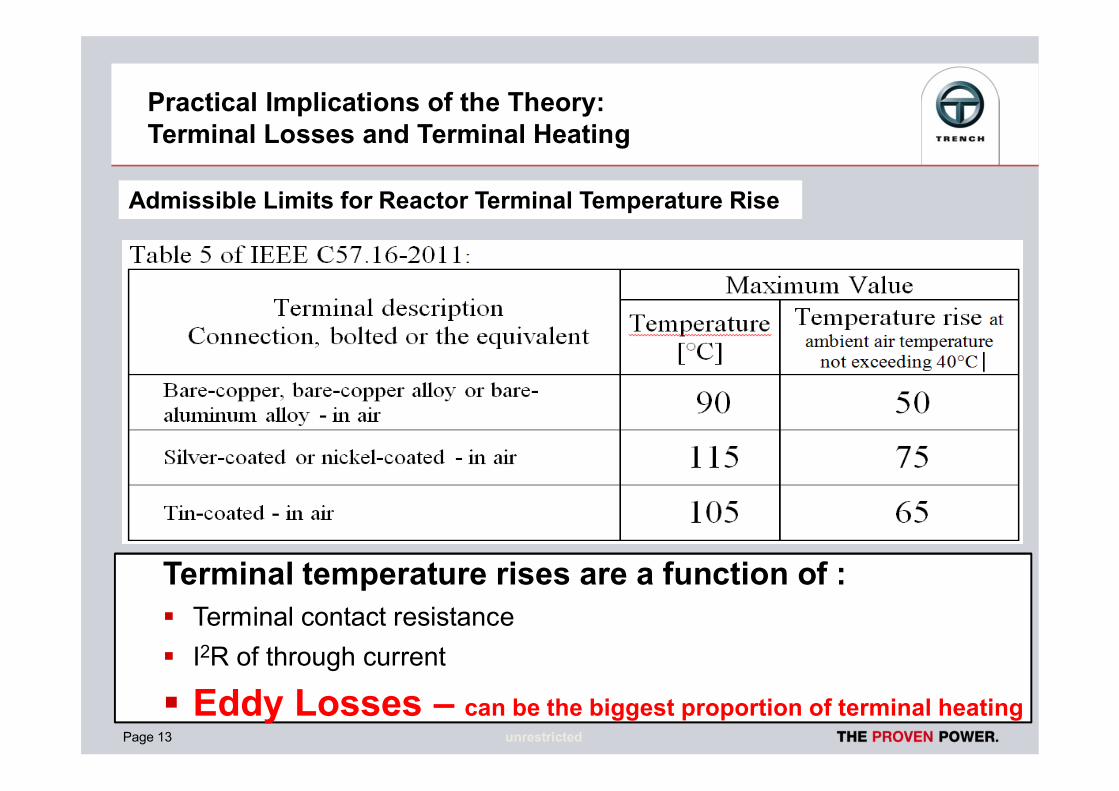
Practical Implications of the Theory:Terminal Losses and Terminal Heating
Terminal temperature rises are a function of :ƒ Terminal contact resistanceƒ I2R of through current
ƒ Eddy Losses – can be the biggest proportion of terminal heating
Admissible Limits for Reactor Terminal Temperature Rise

Page 14 unrestricted
Practical Implications of the Theory:Eddy Losses in Terminals and Connectors
60mT30mT

Page 15 unrestricted
Eddy Losses in Terminals and ConnectorsConnector Loss as a function of Connector Thickness
Reactor Data:• 3160A• 19mH• Mvar50 = 59.6• OD : 128 in.• Length : 47 in.
Optimum connector thickness approx. 10 – 12mm (3/8 to 1/2 in.)

Page 16 unrestricted
Eddy Losses in Terminals and ConnectorsConnector Loss as a function of Thickness and Orientation
Over 50%increase inconnectorlosses bychangingconnectororientation
Page 17 unrestricted
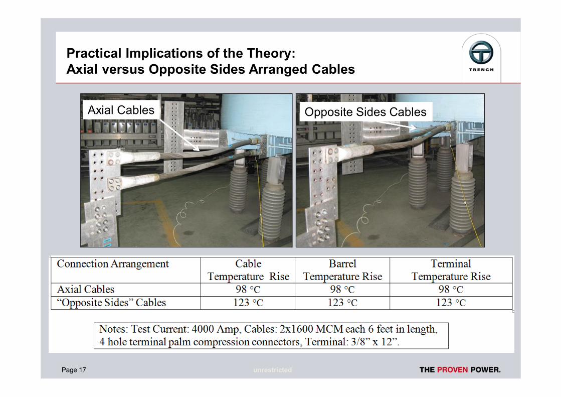
Practical Implications of the Theory:Axial versus Opposite Sides Arranged Cables
Axial Cables Opposite Sides Cables

Page 18 unrestricted
Practical Implications of the Theory:Inappropriate Connection Case Study : Tangential Cables
TCR1: 8 ohm, 3283 Amp85.7 Mvar/phase

Page 19 unrestricted
Practical Implications of the Theory:Inappropriate Connection Case Study : Tangential Cables
Radial FieldLinking CableLoops
Test Setup
35mT

Page 20 unrestricted
Practical Implications of the Theory:Recommended Connection
ƒ radial connection(minimizes forces andflux linkages)ƒ perpendicular to coil
vertical axisƒ bus support or axially
arranged cablesƒ sufficient cable sag –
mechanical isolation

Page 21 unrestricted
Practical Implications of the Theory:Recommended Connector Design
ƒ axially arranged cablesƒ minimize profile to radial fieldƒ connected on one side of terminal
onlyƒ minimize connector thickness (1/2
inch or less)ƒ Stainless bolts & bellville washers

Page 22 unrestricted
Practical Implications of the Theory:Circulating Currents in Horizontal Plane Loops - Foundations
Problem:ƒ I2R heating of rebar,
foundation cracking,short circuit forces
Solutions(alternatives):ƒ Use fiberglass rebarƒ Isolate rebar
crossovers with hoseƒ Maintain at least MC2
clearance
Horizontalplane rebar
loopslinking axial
fluxcomponent

Page 23 unrestricted
Practical Implications of the Theory:Circulating Currents in Fences and Ground Grid
I
I
Problem:
ƒ Induced currents inloops formed by fenceencircling complete setof reactors
ƒ Involvement of highresistance contact atgate latch and lock

Page 24 unrestricted
Practical Implications of the Theory:Circulating Currents in Fences and Ground Grid
Problem:ƒ Induced currents in vertical plane loops and ground
grid formed by the fence and multiple fence groundswhich are typically provided to satisfy NESCgrounding/step and touch requirements
I

Page 25 unrestricted
Practical Implications of the Theory:Circulating Currents in Fences and Ground Grid
Solutions:ƒ Sectionalize fence to allow
multiple groundsƒ ground each section of the
fence in only one locationƒ provide a parallel (to latch and
lock) low resistance copperpath for current to flow fromthe gate to the adjacent postground connectionƒ avoid vertical plane loops by
using insulated stringer wires
Solutions:Safety first – satisfy NESC &IEEE 80 grounding guidelines

Page 26 unrestricted
Practical Implications of the Theory:Circulating Currents in Fences and Ground Grid
Problem:ƒ Loops created by
connecting fences tometal buildingsƒ High resistance contact
>> severe local heatingSolution:ƒ do not connect fences to
metal buildings – use anadjacent post & separateground for the building

Page 27 unrestricted
Practical Implications of the Theory:Circulating Currents in Reactor Supports
Problem:
ƒ closed loops formed by lattice structure (oftensteel) >> loop current (I) >> heating, forces
Solution (alternatives):ƒ maintain at least MC2 clearance
ƒ isolate joints to avoid closed loops(not easy)
ƒ utilize a radial arm structure
ƒ purchase purpose built structures from thereactor supplier
I
Page 28 unrestricted
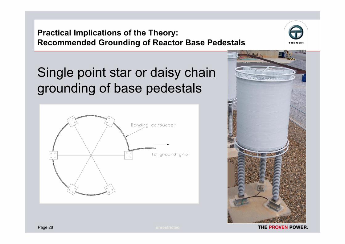
Single point star or daisy chaingrounding of base pedestals
Practical Implications of the Theory:Recommended Grounding of Reactor Base Pedestals

Page 29 unrestricted
Conclusions & Summary
General:ƒ Stray fields: eddy currents, closed loop currents,
losses, forcesƒ for “small” reactors, all of this is less criticalConnections:ƒ radial connection (minimizes forces and flux linkages)ƒ axially arranged cables are the bestConnectors:ƒ minimize the profile to the stray field; more metal
does not necessarily mean cooler terminals

Page 30 unrestricted
Conclusions & Summary (continued)
Fences:ƒ Safety > satisfy NESC & IEEE 80ƒ segmentation, single point grounding of fence
segmentsƒ grounding: avoid loops involving the ground gridCoil Support Structures:ƒ radial cross arms are better than steel lattice
structuresƒ single point connection to the ground grid (daisy
chain or star)

Page 31 unrestricted
Conclusions & Summary (continued)
managing air core reactor magneticclearances, connections and grounding is
fairly straightforward,
… once the principles are understood

Page 32 unrestricted
Thank youfor your attention!
Page 33 unrestricted
Questions ?

Page 34 unrestricted
David CaverlyVP Business DevelopmentCoil Products
71 Maybrook DriveScarborough, Ontario, M1V4B6Canada
Phone: +1 416 298-8108 ext 231Fax: +1 416 298-2209Mobile: +1 416 953-3796
E-mail: [email protected]