Embed Size (px)
Citation preview
18
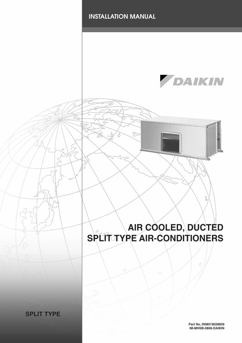
AIR COOLED, DUCTEDSPLIT TYPE AIR-CONDITIONERS
SPLIT TYPE
INSTALLATION MANUAL
Part No.:R08019028859IM-MHSB-0806-DAIKIN

1
En
gli
s h
FD75BV1M / FD100BV1M
OUTLINE AND DIMENSIONS
FD125BY1M / FD150BY1M

2
FD200B2Y1M
FD250B2Y1M / FD300B2Y1M

3
En
gli
s h
FD350B3Y1M
FD400B4Y1M/FD500B4Y1M

4
FD450B3Y1M
FD600B4Y1M

5
En
gli
s h
R100BY1M / R125BY1M
NOTE:FOR VERTICAL AIR DISCHARGE
950
11 200
716
200
11
939
946
50
1116
R75CY1M
1300
524
180 940 180
432
432
41
408.5 408.5 422 500
946

6
R150CY1M
11
950
11
716
200
200
50
939
9594
6
1041
1116

7
En
gli
s h
INSTALLATION OF THE INDOOR UNIT
MountingEnsure that the overhead supports are strong enough to hold theunit’s weight. Position hanger rods and check for alignment withthe unit. Check that hangers are secure and that the base of fan-coil unit is level in the two horizontal directions, taking intoaccount the gradient recommended for drainage flow as shown.
Check the gradient recommended for drainage flow asfollow.
Provide clearance for servicing and optimal air flow as shownin the diagram.
The indoor unit must be installed such that there is no shortcircuit of cool discharge with air discharge.Respect the installation clearance.
*for free return of air
FD125BY1M ~ FD200B2Y1M (Horizontal)
FD250B2Y1M ~ FD600B4Y1M (Vertical)
** For FD400B4Y1M ~ FD600B4Y1M
SAFETY PRECAUTIONS
! WARNING• Installation and maintenance should be performed by
qualified persons who are familiar with local code andregulation, and experienced with this type of appliance.
• All field wiring must be installed in accordance with thenational wiring regulation.
• Ensure that the rated voltage of the unit corresponds tothat of the name plate before commencing wiring workaccording to the wiring diagram.
• The unit must be GROUNDED to prevent possible hazarddue to insulation failure.
• All electrical wiring must not touch the refrigerant piping,compressor and any moving parts of the fan motors.
• Confirm that the unit has been switched OFF beforeinstalling or servicing the unit.
• DO NOT INSTALL OR USE THE AIR CONDITIONERUNIT IN A LAUNDRY ROOM.
• Disconnect from the main power supply before servicingthe air conditioner unit.
• DO NOT pull out the power cord when the power is ON.This may cause serious electrical shocks which may resultin fire hazards.
• Troubleshooting must be performed by qualifiedpersonnel.
! CAUTIONPlease take note on the following important points wheninstalling.• Do not install the unit where leakage of flammable gas may
occur.If gas leaks and accumulates around the unit, it may causefire ignition.
• Ensure that the drainage piping is connected properly.If the drainage piping is not connected properly, it may causewater leakage which will dampen the furniture.
• Do not overcharge the unit.This unit is factory pre-charged. Overcharge will cause over-current or damage to the compressor.
• Ensure that the units panel is closed after service or installation.Unsecured panels will cause the unit to operate noisily.
• Sharp edges and coil surfaces are potential locations whichmay cause injury hazards. Avoid from being in contact withthese places.
• If the condensing unit is operated in an atmosphere containingoils (including machine oils), salt (coastal area), sulfide gas(near hot spring, oil refinery plant), such substances may leadto failure of the unit.
• Our guarantee on the performance of our air-conditioners isstrictly revoked if the height, length and/or no. of bends of therefrigerant piping system installed is beyond the limit above.
• Manifold Gauge will show cylinder pressure rather thansuction pressure if the cylinder valve and Manifold valve “A”are open.
• Before turning off the power supply, set the remote controller'sON/OFF switch to the “OFF” position to prevent the nuisancetripping of the unit. If this is not done, the unit's fans will startturning automatically when power resumes, posing a hazard toservice personnel or the user.
• Do not operate any heating apparatus too close to the airconditioner unit. This may cause the plastic panel to melt ordeform as a result of the excessive heat.
10
50mm
300mm*
500mm
300mm
300mm
800 800
800
800 800
8001000
**1500

8
Installation ClearanceOutdoor unit must be installed such that there is no short circuit of the discharge air or obstruction to smooth air flow.
Minimum distance (mm) A B CFD75BV1M 300 1200 500
FD100BV1M/FD125BY1M/FD150BY1M 300 1000 1500
Maximum Pipe Length And Maximum No. Of Bends
When the pipe length becomes too long, both the capacity and reliability will drop and as the no. of bends increases, systempiping resistance to the refrigerant flow increases, thus lowering the capacity. As a result the compressor may fail. Always choosethe shortest path and follow the recommendations as tabulated below:-
Model R75CY1M / R100BY1M / R125BY1M / R150CY1MMax. Length 35m
Max. Elevation 20mMax. no. of Bends 10
Bending must be carefully made so as not to crush the pipe. Use a pipe bender to bend a pipe where possible.
Remark: For cooling unit FD75BV1M & FD100BY1M / FD150BY1M, recommended to add 6 kg & 10 kg external accumulatorrespectively.
Obs
tacl
e
Obs
tacl
e
Obs
tacl
e
Obs
tacl
e
Serv
ice
Acc
ess
Ret
urn
Air
Dis
char
ge A
ir
Ret
urn
Air
Air Discharge Space
REFRIGERANT PIPING
INSTALLATION OF THE OUTDOOR UNIT
Location For Installation
Install the outdoor unit in such way that air distributed by theoutdoor unit cannot be drawn in again (as in the case of shortcircuit of discharge air). Allow sufficient space for maintenancearound the unit.
Ensure that there are no obstruction of air flow into orout of the unit. Remove obstacles which block air intakeor discharge.
When two or more outdoor units are installed in a location, theymust be positioned such that one unit will not be taking thedischarge air from another.
This also applies when two or more units are installed one abovethe other. The units must all face the same direction, or oppositedirection (back to back), such that air short circuit does not occur.
The location must be well ventilated, so that the unit can draw and distribute plenty of air.A place capable of bearing the weight of the outdoor unit and isolating noise and vibration.A place protected from direct sunlight. Otherwise use an awning for protection, if necessary.A place where smooth drainage of rain water and water formed by defrosting is acceptable.A place where the unit will not be buried in snow.A place where air outlet port is not exposed to strong wind.A place where the air discharge and operating sound level will not annoy the neighbours.The location must not be susceptible to dust or oil mist.
A B C D
A
A B
A
C

9
En
gli
s h
Remove Burr
SpanarTorque Wrench
Indoor PipingFlare Nut
Flared TubeFlare Joint
Cutting Copper Tube
Piping Connection To The Units
• Align the center of the piping and tighten the flare nutsufficiently with fingers.
• Finally, tighten the flare nut with the torque wrenchuntil the wrench clicks.
• When tightening the flare nut with the torque wrench,ensure that the tightening direction follows the arrow in-dicated on the wrench.
Pipe Size (mm/in) Torque (Nm)
6.35 (1/4") 189.53 (3/8") 4212.7 (1/2") 5515.88 (5/8") 6519.05 (3/4") 78
Piping Works & Brazing Technique
• Do not use contaminated or damaged copper tubing. If anypipings, evaporator or condenser had been exposed or hadbeen opened for 15 seconds or more, then vacuum and purgewith field supplied refrigerant. Generally, do not remove plas-tic, rubber plugs and brass nuts from the valves, fittings,tubings and coils until it is ready to connect suction or liquidline into valves or fittings.
• If any brazing work is required, ensure that the nitrogen gasis passed through coil and joints while the brazing work isbeing done. This will eliminate soot formation on the insidewalls of the copper tubings.
• Cut the pipe stage by stage, advancing the blade of the pipecutter slowly. Extra force and deep cut will cause more dis-tortion on the pipe and thus extra burr. See figure.
• Remove burrs from cut edges of the pipes with remover asshown in the figure. Hold the end of the pipe downwards toprevent metal chips from entering the pipe.
Copper Tube
1/4t
Special Precautions When Mounting TXV Bulb
• TXV bulb should be clamped to the suction line near the evaporator outlet, and if possible, on a horizontal run.• Clean suction line completely before clamping the bulb in place.• Clamp the bulb to a free draining suction line.• Insulate the remote bulb from ambient.
Note: After installation is done, the TXV bulb must be fixed at suction line at 8 o’clock or 4 o’clock.
Figure – TXV bulb placement in relation to suction line size
TXV Bulb on small Suction Line TXV Bulb on large Suction Line
10
L
N
E
COMP
L
N
COMP
R
S
T
N
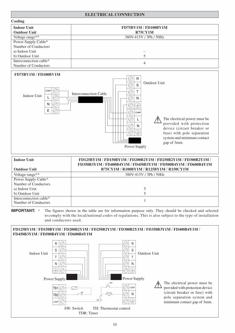
Cooling
Indoor Unit FD75BV1M / FD100BV1MOutdoor Unit R75CY1MVoltage range** 380V-415V / 3Ph / 50HzPower Supply Cable*Number of Conductorsa) Indoor Unit –b) Outdoor Unit 5Interconnection cable*
4Number of Conductors
The electrical power must beprovided with protectiondevice (circuit breaker orfuse) with pole separationsystem and minimum contactgap of 3mm.
!
Indoor Unit
Outdoor Unit
Interconnection Cable
FD75BV1M / FD100BV1M
Power Supply
IMPORTANT: * The figures shown in the table are for information purpose only. They should be checked and selectedto comply with the local/national codes of regulations. This is also subject to the type of installationand conductors used.
Indoor Unit FD125BY1M / FD150BY1M / FD200B2Y1M / FD250B2Y1M / FD300B2Y1M /FD350B3Y1M / FD400B4Y1M / FD450B3Y1M / FD500B4Y1M / FD600B4Y1M
Outdoor Unit R75CY1M / R100BY1M / R125BY1M / R150CY1MVoltage range** 380V-415V / 3Ph / 50HzPower Supply Cable*Number of Conductorsa) Indoor Unit 5b) Outdoor Unit 5Interconnection cable*
1Number of Conductors
The electrical power must beprovided with protection device(circuit breaker or fuse) withpole separation system andminimum contact gap of 3mm.
!
Indoor Unit Outdoor Unit
FD125BY1M / FD150BY1M / FD200B2Y1M / FD250B2Y1M / FD300B2Y1M / FD350B3Y1M / FD400B4Y1M /FD450B3Y1M / FD500B4Y1M / FD600B4Y1M
N
T
S
R
TB1
TB2
N
T
S
R
N
COMP
COMP
SW
SW
TDR
TH
SW: Switch TH: Thermostat controlTDR: Timer
Power SupplyPower Supply
ELECTRICAL CONNECTION

11
En
gli
s hVacuuming is necessary to eliminate all moisture and air from the system. The series II Outdoor Unit is provided withflare valve fittings.
Vacuuming
Before vacuuming, perform leak check for refrigeration circuit.After the system piping are properly connected, connect the flex-ible hoses to the correct charging nipples as shown in the dia-gram. Ensure that flexible hose from charging nipples are con-nected to the vacuum pump via standard servicing valves andpressure gauges (gauge manifold). Vacuum the air conditionersystem to at least 500 microns Hg. Do not start the unit whenthe system is engaged in vacuuming.
Charging
Before charging, the vacuum must be held at 500 microns Hgfor at least 15 minutes, then break vacuum by charging R-22refrigerant. Operate the unit for 15 minutes and ensure the re-frigerant charges is of correct by monitoring running current,gas and liquid line pressures. Suction and discharge pipe pres-sure should be in the region of 75 psig and 275 psig generally.
After ensuring the system is correctly charged, remove flexiblehose from charging nipples and replace caps.
Gas Pipe
Liquid Pipe
Gas Pipe
Liquid Pipe
Vacuum Pump
VACUUMING AND CHARGING
SYSTEM REFRIGERANT CHARGE LEVEL GUIDELINES
Cooling Only
Indoor Outdoor Liquid Pipe Gas Pipe CFM Refrigerant Charge(kg/7.5m pipe length)
FD75BV1M R75CY1M 1/2" 1" 2500 4.50FD100BV1M R100BY1M 5/8" 1-1/8" 3200 7.60FD125BY1M R125BY1M 5/8" 1-3/8" 4200 7.95FD150BY1M R150CY1M 5/8" 1-3/8" 4600 10.10FD200B2Y1M R100BY1M x 2 5/8" 1-1/8" 6400 7.60 x 2FD250B2Y1M R125BY1M x 2 5/8" 1-3/8" 8000 7.95 x 2FD300B2Y1M R150BY1M x 2 5/8" 1-3/8" 9000 7.60 x 3FD350B3Y1M R100BY1M + R125BY1M x 2 5/8" 1-1/8" & 1-3/8" 10500 7.60 + (7.95 x 2)FD400B4Y1M R100BY1M x 4 5/8" 1-1/8" 12000 7.60 x 4FD450B3Y1M R150CY1M x 3 5/8" 1-3/8" 13500 10.10 x 3FD500B4Y1M R125BY1M x 4 5/8" 1-3/8" 15000 7.95 x 4FD600B4Y1M R150CY1M x 4 5/8" 1-3/8" 18000 10.10 x 4
ADDITIONAL CHARGE
Based on liquid pipe size per meter length:
Liquid Pipe Size, inch Additional Charge, kg/meter1/4" 0.02
5/16" 0.043/8" 0.051/2" 0.105/8" 0.173/4" 0.267/8" 0.37
Note: Refer to the table of the Recommende Maximum Pipe Length.

12
These precautions are intended for use with Copeland Scroll compressors only with R22, R407C, R134A, R404A, R507 and R410Arefrigerants but are not applied to Copeland reciprocating compressors or competitive Scroll compressors.
Scroll compressors have a very high volumetric efficiency and quickly pump a deep vacuum if there is insufficient refrigerant in thesystem or if refrigerant is added too slowly. Operation with low suction pressure will quickly lead to very high discharge tempera-tures. While this process is happening, the scrolls are not being well lubricated – scrolls depend on the oil mist in the refrigerant forlubrication. A lack of lubrication leads to high friction between the scroll flanks and tips and generates additional heat. The combina-tion of heat of compression and heat from increased friction is concentrated in a small localized discharge area where temperaturescan quickly rise to more than 300˚C. These extreme temperatures damage the Scroll spirals and the orbiting Scroll bearing. Thisdamage can occur in less than one minute especially on larger compressors. Failure may occur in the first few hours or the damagedone during field charging may show up some time later.
Other typical field charging problems include undercharging, overcharging, moisture or air in the system etc. In time each one ofthese problems can cause compressor failure.
Minimal equipment is required for field charging. The minimum equipment required to do a satisfactory job is:-
Set of service gauges Vacuum gauge
Hoses Scales
Vacuum pump Thermometer
The proper refrigerant charge should follow the volume as recommended by manufacturer and recommendation should be followedby the installer.
1. Charging procedures – Single phase compressors
Evacuate the system to 500 microns Hg. (67Pa). To reduce evacuation time, use short, large diameter hoses and connect tounrestricted service ports on the system. Quality of vacuum cannot be determined by time – a reliable vacuum gauge must beused. (etc. electronic vacuum gauge)
Turn the refrigerant cylinder upside down, purge the charging hose and charge liquid through the liquid line charging port untilrefrigerant no longer flows or until the correct charge has been weighed in. If additional charge is required start the system andslowly bleed liquid into the suction side until the system is full.
Copeland recommends charging liquid in a CONTROLLED manner into the suction side until the system is full. Thisrecommendation does not hold true for reciprocating compressors where liquid charging into the suction side could cause severedamage.
Carefully monitor the suction and discharge pressures – ensure that the suction pressure does not fall below 25 psig (1.7 bar) atany time during the charging process.
There are many ways of charging liquid in a “controlled manner” into the suction side:-1. Use valve A on the manifold gauge set2. Use the valve on the refrigerant cylinder3. Charge through a Shredder valve4. Use a hose with a Shredder valve depressor5. Charge into the suction side at some distance from the compressor6. All of the aboveA
SPECIAL PRECAUTIONS WHEN CHARGING UNIT WITHCOPELAND SCROLL COMPRESSORS
2. Charging procedures – Three phase compressors
The fundamental procedure is the same as for single phase models but the compressor can run in the wrong direction on starting.If this happens reverse any two phases and start again. Short term reverse rotation will not damage the compressor.
All Specter compressors have internal discharge temperature protectors which are very effective in preventing dangerously highdischarge temperatures during charging. The protection module will trip and lock the compressors out for 30 minutes. It is notnormally necessary to wait 30 minutes for the module to reset. When the compressor has cooled down the module can be reset bybreaking the power supply to the control circuit. Very often the serviceman does not understand why the module tripped and usesa jumper wire to bypass it. He continues to charge the system and removes the jumper when charging is complete. The compressormay or may not run with the protector back in the circuit but it is certain that the compressor has been damaged and prematurefailure is inevitable.

13
En
gli
s hCooling
Temperature Ts °C Th °CMinimum indoor
16 11temperature
Maximum indoor32 23temperature
Minimum outdoor16 11temperature
Maximum outdoor46 24temperature
Ts: Dry bulb temperature.Th: Wet bulb temperature.
If there is a power cut when the unit is operating, it will automatically resume the same operating mode when the power is restored.(Applicable only to units with this feature)
STANDARD OPERATING CONDITIONS
AUTO RANDOM RE-START FUNCTION
Maintenance Procedures
1. Remove any dust adhering to the filter by using a vacuum cleaner orwash in lukewarm water (below 40°C) with a neutral cleaning detergent.
2. Rinse the filter well and dry before placing it back onto the unit.
3. Do not use gasoline, volatile substances or chemicals to clean the filter.
1. Clean any dirt or dust on the grille or panel by wiping it with a softcloth soaked in lukewarm water (below 40°C) and a neutral detergentsolution.
2. Do not use gasoline, volatile substances or chemicals to clean theindoor unit.
Period
At least once every 2weeks.
More frequently ifnecessary.
At least once every 2weeks.
More frequently ifnecessary.
Service Parts
Indoor air filter
Indoor unit
SERVICE AND MAINTENANCE

14
If any malfunction of the air conditioner unit is noted, immediately switch off the power supply to the unit. Checkthe following fault conditions and causes for some simple troubleshooting tips.
Causes / Action
- Protection against frequent starting. Wait for 3 to 4 minutes for thecompressor to start operating.
- Power failure, or the fuse needs to be replaced.
- The power plug is disconnected.
- It is possible that your delay timer has been set incorrectly.
- If the fault persist after all these verifications, pleasecontact the air conditioner unit installer.
- The air filter is dirty.
- The doors or windows are open.
- The air suction and discharge are clogged.
- The regulated temperature is not high enough.
- Odors may be caused by cigarettes, smoke particles, perfume etc.which might have adhered onto the coil.
- This is caused by air humidity after an extended long period ofoperation.
- The set temperature is too low, increase the temperature settingand operate the unit at high fan speed.
- Switch off unit and call dealer.
- Refrigerant fluid flowing into the evaporator coil.
Fault
1. The compressor does not operate 3 minutes after the air condi-tioner unit is started.
2. The air conditioner unit does not operate.
3. The air flow is too low.
4. Discharge air flow has bad odor.
5. Condensation on the front air grille of the indoor unit.
6. Water flowing out from the air conditioner unit.
7. Hissing air flow sound from the air conditioner unit during op-eration.
If the fault persists, please call your local dealer / serviceman.
TROUBLESHOOTING
The unit with Scroll Compressor can only rotate in one direction. For this reason, a protective device (phase protector) is fitted toprevent incorrect wiring of the electrical phases. When the three phases are not connected correctly, the phase protector operates,and the unit will not start. This devise is located in the control box of the outdoor unit.
The following table shows the LED indicator light for phase protector under normal operation and fault conditions.
Notes: 1. “+” indicates additional functions for PP01 phase protector.2. When R phase missing, no LED or buzzer will indicate the error, but relay 71 and relay 81 will cut off.
Normal operation
Reverse phase
T phase missing
S phase missing
R phase missing
S &T phase missing+
Overload+
Sensor missing+
-
Switch off the unit. Check the 3 phase wiring.
Switch off the unit. Check the 3 phase wiring.
Switch off the unit. Check the 3 phase wiring.
Switch off the unit. Check the 3 phase wiring.
Switch off the unit. Check the 3 phase wiring.
High discharge temperature. Check the refrigerant system.
Switch off the unit. Plug in sensor.
LEDDescription
PW(Red)
P_R(Yellow)
P_S(Yellow)
P_T(Yellow) Actions
ON OFF Fast Blink
PHASE PROTECTOR (OPTIONAL)

15
En
gli
s h
MEMO

16
MEMO

17
En
gli
s h
• In the event that there is any conflict in the interpretation of this manual and any translation of the same in any languages, theENGLISH version of this manual shall prevail.
• The manufacturer reserves right to revise any of the specification and design contain herein at any time without prior notification.
OYL MANUFACTURING COMPANY SDN. BHD.JALAN PENGAPIT 15/19, P.O. BOX 7072, 40702 SHAH ALAM, SELANGOR DARUL EHSAN, MALAYSIA.