Embed Size (px)
Citation preview
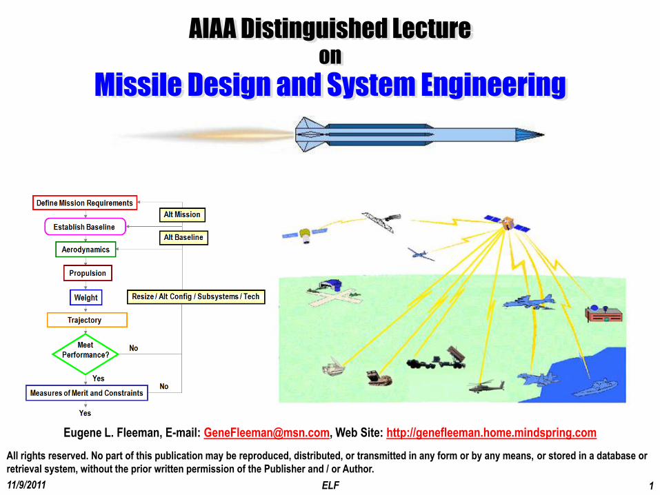
11/9/2011 ELF 1
All rights reserved. No part of this publication may be reproduced, distributed, or transmitted in any form or by any means, or stored in a database or
retrieval system, without the prior written permission of the Publisher and / or Author.
Eugene L. Fleeman, E-mail: [email protected], Web Site: http://genefleeman.home.mindspring.com
AIAA Distinguished Lecture on
Missile Design and System Engineering
11/9/2011 ELF 2
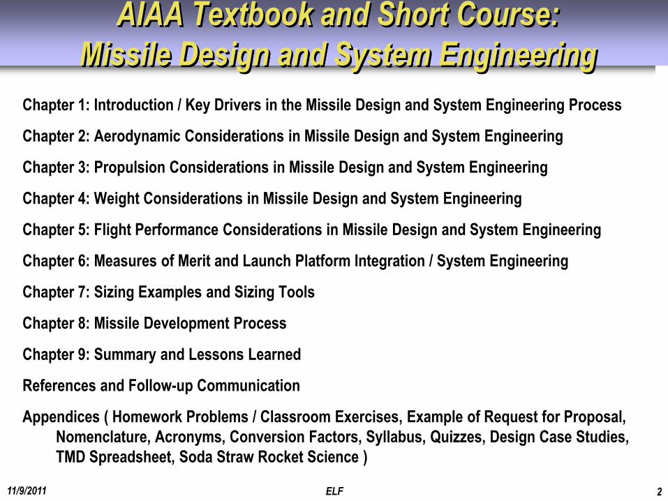
AIAA Textbook and Short Course:
Missile Design and System Engineering
Chapter 1: Introduction / Key Drivers in the Missile Design and System Engineering Process
Chapter 2: Aerodynamic Considerations in Missile Design and System Engineering
Chapter 3: Propulsion Considerations in Missile Design and System Engineering
Chapter 4: Weight Considerations in Missile Design and System Engineering
Chapter 5: Flight Performance Considerations in Missile Design and System Engineering
Chapter 6: Measures of Merit and Launch Platform Integration / System Engineering
Chapter 7: Sizing Examples and Sizing Tools
Chapter 8: Missile Development Process
Chapter 9: Summary and Lessons Learned
References and Follow-up Communication
Appendices ( Homework Problems / Classroom Exercises, Example of Request for Proposal,
Nomenclature, Acronyms, Conversion Factors, Syllabus, Quizzes, Design Case Studies,
TMD Spreadsheet, Soda Straw Rocket Science )
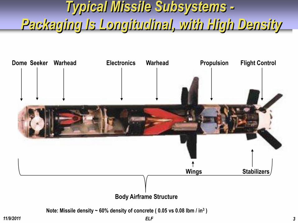
Body Airframe Structure
Typical Missile Subsystems -
Packaging Is Longitudinal, with High Density
11/9/2011 ELF 3
Dome Seeker Warhead Electronics Warhead Propulsion Flight Control
Wings Stabilizers
Note: Missile density ~ 60% density of concrete ( 0.05 vs 0.08 lbm / in3 )
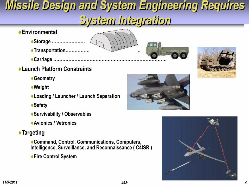
Missile Design and System Engineering Requires
System Integration
11/9/2011 ELF 4
Environmental
Storage ………………….
Transportation…………………………………………..
Carriage …………………………………………………………………
Launch Platform Constraints
Geometry
Weight
Loading / Launcher / Launch Separation
Safety
Survivability / Observables
Avionics / Vetronics
Targeting
Command, Control, Communications, Computers, Intelligence, Surveillance, and Reconnaissance ( C4ISR )
Fire Control System
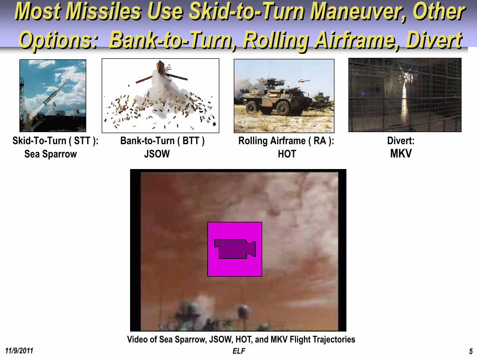
Most Missiles Use Skid-to-Turn Maneuver, Other
Options: Bank-to-Turn, Rolling Airframe, Divert
11/9/2011 ELF 5
Skid-To-Turn ( STT ): Bank-to-Turn ( BTT ) Rolling Airframe ( RA ): Divert:
Sea Sparrow JSOW HOT MKV
Video of Sea Sparrow, JSOW, HOT, and MKV Flight Trajectories
11/9/2011 ELF 6
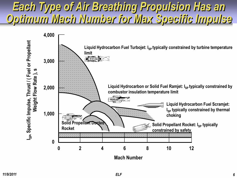
Liquid Hydrocarbon Fuel Scramjet:
ISP typically constrained by thermal
choking
Each Type of Air Breathing Propulsion Has an Optimum Mach Number for Max Specific Impulse
Liquid Hydrocarbon Fuel Turbojet: ISP typically constrained by turbine temperature
limit
Liquid Hydrocarbon or Solid Fuel Ramjet: ISP typically constrained by
combustor insulation temperature limit
Solid Propellant Rocket: ISP typically
constrained by safety
4,000
3,000
2,000
1,000
0
I SP,
Sp
ecif
ic Im
pu
lse,
Th
rust
/ (
Fu
el o
r P
rop
ella
nt
Wei
gh
t F
low
Rat
e ),
s
0 2 4 6 8 10 12
Mach Number
Solid Propellant Ducted
Rocket
11/9/2011 ELF 7
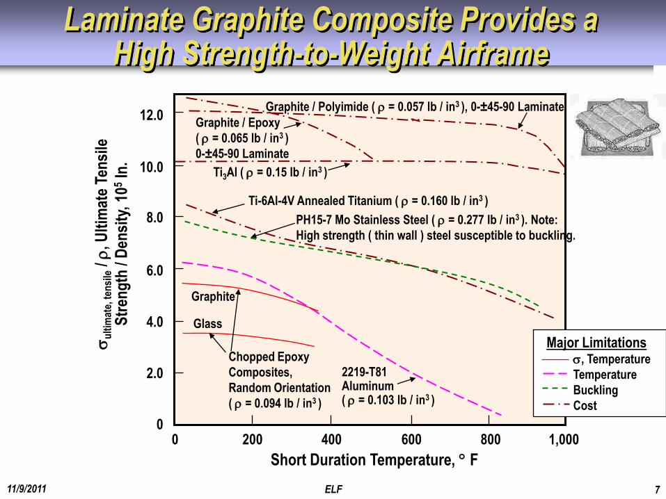
Laminate Graphite Composite Provides a High Strength-to-Weight Airframe
200 400 600 800 1,000 0
Short Duration Temperature, F
8.0
10.0
12.0
6.0
4.0
2.0
0
u
ltim
ate,
ten
sile
/
, Ult
imat
e Te
nsi
le
Str
eng
th /
Den
sity
, 10
5 In
. Graphite / Epoxy
( = 0.065 lb / in3 )
0-±45-90 Laminate
Graphite / Polyimide ( = 0.057 lb / in3 ), 0-±45-90 Laminate
Ti-6Al-4V Annealed Titanium ( = 0.160 lb / in3 )
PH15-7 Mo Stainless Steel ( = 0.277 lb / in3 ). Note:
High strength ( thin wall ) steel susceptible to buckling.
Graphite
Glass
2219-T81 Aluminum ( = 0.103 lb / in3 )
Chopped Epoxy
Composites,
Random Orientation
( = 0.094 lb / in3 )
Ti3Al ( = 0.15 lb / in3 )
Major Limitations , Temperature
Temperature
Buckling
Cost
11/9/2011 ELF 8
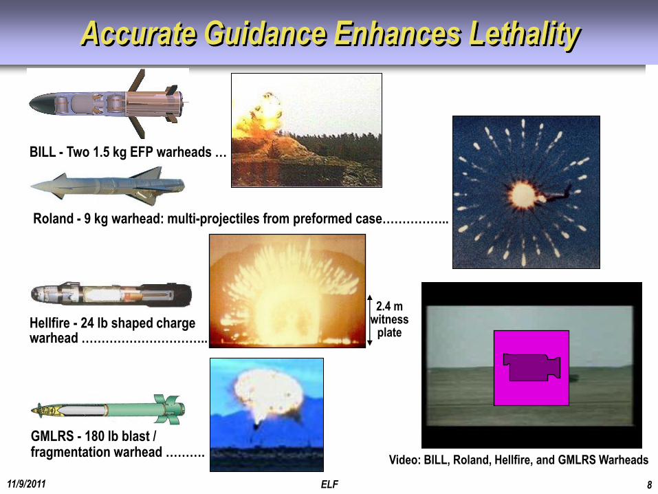
Accurate Guidance Enhances Lethality
Hellfire - 24 lb shaped charge warhead …………………………..
2.4 m witness
plate
Roland - 9 kg warhead: multi-projectiles from preformed case……………..
GMLRS - 180 lb blast / fragmentation warhead ……….
Video: BILL, Roland, Hellfire, and GMLRS Warheads
BILL - Two 1.5 kg EFP warheads …
11/9/2011 ELF 9
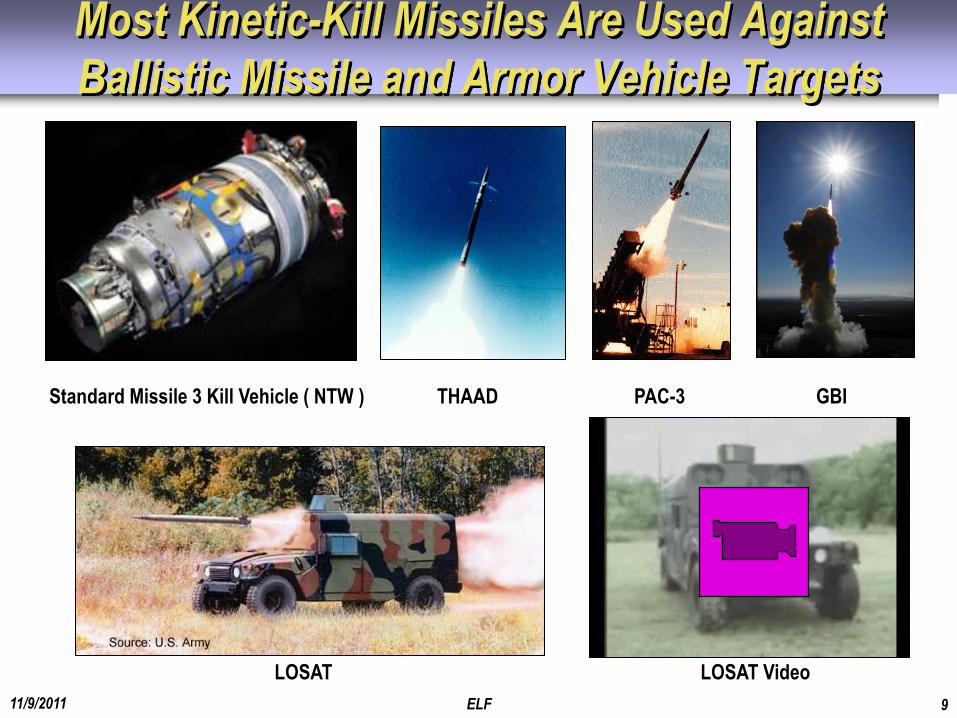
Standard Missile 3 Kill Vehicle ( NTW ) THAAD PAC-3 GBI
LOSAT LOSAT Video
Most Kinetic-Kill Missiles Are Used Against
Ballistic Missile and Armor Vehicle Targets
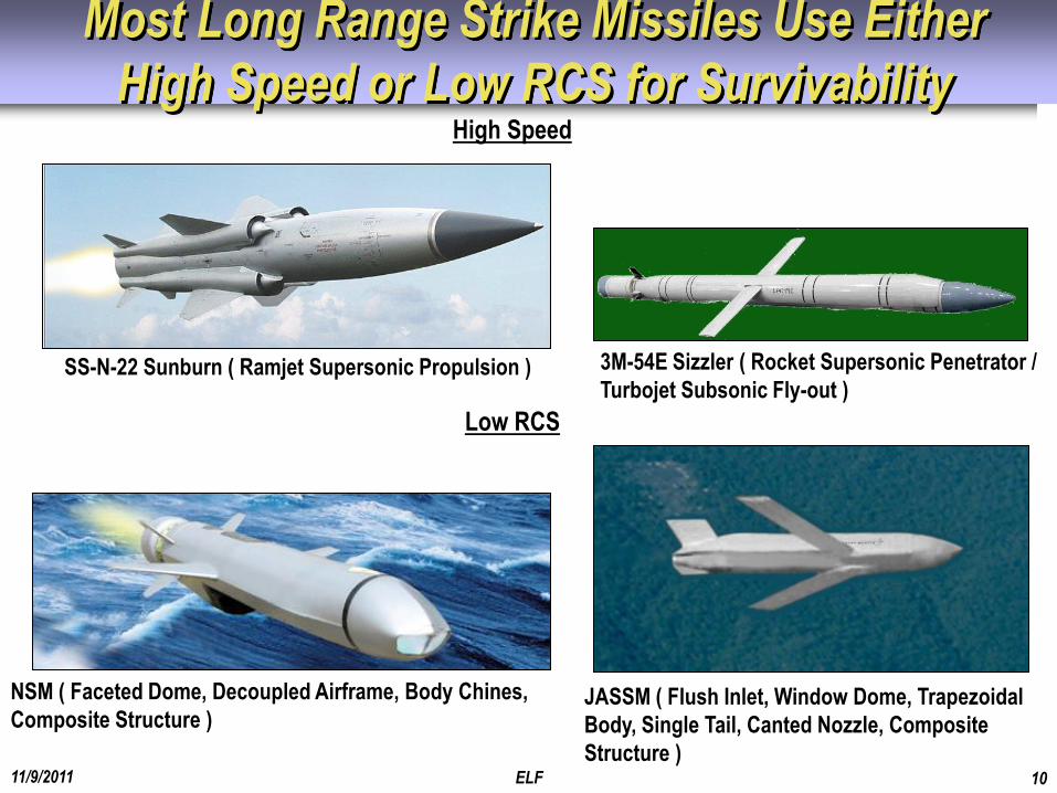
Most Long Range Strike Missiles Use Either
High Speed or Low RCS for Survivability
11/9/2011 ELF 10
SS-N-22 Sunburn ( Ramjet Supersonic Propulsion )
NSM ( Faceted Dome, Decoupled Airframe, Body Chines,
Composite Structure )
High Speed
Low RCS
3M-54E Sizzler ( Rocket Supersonic Penetrator /
Turbojet Subsonic Fly-out )
JASSM ( Flush Inlet, Window Dome, Trapezoidal
Body, Single Tail, Canted Nozzle, Composite
Structure )
11/9/2011 ELF 11
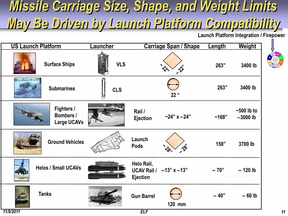
Missile Carriage Size, Shape, and Weight Limits
May Be Driven by Launch Platform Compatibility
Surface Ships
CLS
~24” x 24”
263” 3400 lb
263” 3400 lb
~168” ~500 lb to
3000 lb
Fighters /
Bombers /
Large UCAVs
Rail /
Ejection
VLS
Submarines
Launch Platform Integration / Firepower
22 “
Ground Vehicles 158” 3700 lb
Helos / Small UCAVs
Launch
Pods
Helo Rail,
UCAV Rail /
Ejection
US Launch Platform Launcher Carriage Span / Shape Length Weight
13” x 13” 70” 120 lb
Tanks Gun Barrel
120 mm
40” 60 lb

11/9/2011 ELF 12
1. Homing Active /
Passive Seeker
Guidance
2. Homing Semi-
Active Seeker
Guidance
3. Command
Guidance
Active Seeker Transmitted Energy
Target Reflected / Emitted Energy
Target Reflected Energy
Rear-looking Sensor Detects
Fire Control System Energy
Missile Guidance / Launch Platform Integration
Varies from Autonomous to Command Guidance
Seeker
Semi-Active Seeker
Fire Control System Tracks Target
Fire Control System Tracks Target, Tracks Missile, and Command Guides Missile
Launch / Midcourse Guidance
Launch / Midcourse Guidance
Launch / Midcourse Guidance
11/9/2011 ELF 13
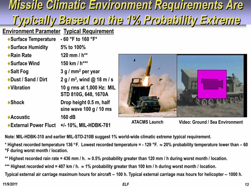
Missile Climatic Environment Requirements Are
Typically Based on the 1% Probability Extreme Environment Parameter Typical Requirement
Surface Temperature - 60 °F to 160 °F*
Surface Humidity 5% to 100%
Rain Rate 120 mm / h**
Surface Wind 150 km / h***
Salt Fog 3 g / mm2 per year
Dust / Sand / Dirt 2 g / m3, wind @ 18 m / s
Vibration 10 g rms at 1,000 Hz: MIL
STD 810G, 648, 1670A
Shock Drop height 0.5 m, half
sine wave 100 g / 10 ms
Acoustic 160 dB
External Power Fluct +/- 10%, MIL-HDBK-781
Note: MIL-HDBK-310 and earlier MIL-STD-210B suggest 1% world-wide climatic extreme typical requirement.
* Highest recorded temperature 136 F. Lowest recorded temperature = - 129 °F. 20% probability temperature lower than – 60
°F during worst month / location.
** Highest recorded rain rate = 436 mm / h. 0.5% probability greater than 120 mm / h during worst month / location.
*** Highest recorded wind = 407 km / h. 1% probability greater than 100 km / h during worst month / location.
Typical external air carriage maximum hours for aircraft 100 h. Typical external carriage max hours for helicopter 1000 h.
ATACMS Launch Video: Ground / Sea Environment
11/9/2011 ELF 14
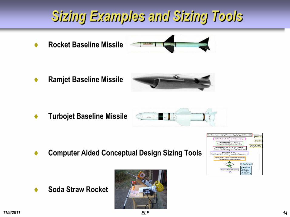
Sizing Examples and Sizing Tools
Rocket Baseline Missile
Ramjet Baseline Missile
Turbojet Baseline Missile
Computer Aided Conceptual Design Sizing Tools
Soda Straw Rocket
11/9/2011 ELF 15
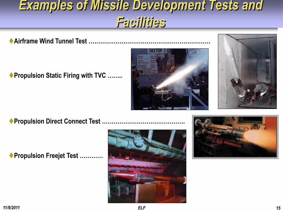
Airframe Wind Tunnel Test ………………………………………………………
Propulsion Static Firing with TVC ……..
Propulsion Direct Connect Test …………………………………….
Propulsion Freejet Test …………
Examples of Missile Development Tests and
Facilities
11/9/2011 ELF 16
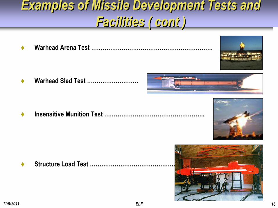
Examples of Missile Development Tests and
Facilities ( cont )
Warhead Arena Test ……………………………………………………….
Warhead Sled Test ………………………
Insensitive Munition Test ……………………………………………..
Structure Load Test …………………………………………..
11/9/2011 ELF 17
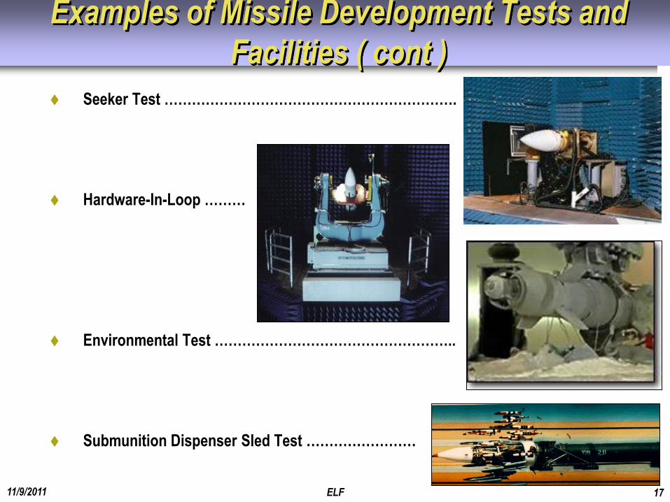
Examples of Missile Development Tests and
Facilities ( cont )
Seeker Test ……………………………………………………….
Hardware-In-Loop ………
Environmental Test ……………………………………………..
Submunition Dispenser Sled Test ……………………
11/9/2011 ELF 18
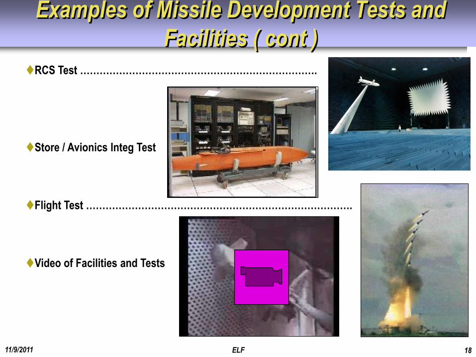
RCS Test ……………………………………………………………….
Store / Avionics Integ Test
Flight Test ……………………………………………………………………….
Video of Facilities and Tests
Examples of Missile Development Tests and
Facilities ( cont )
11/9/2011 ELF 19
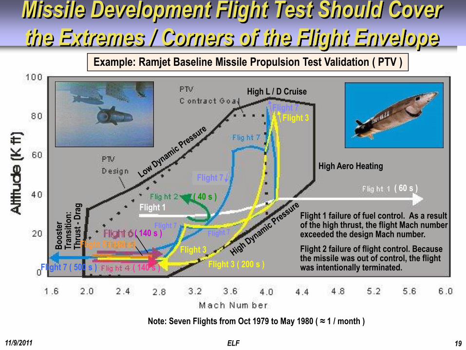
Missile Development Flight Test Should Cover
the Extremes / Corners of the Flight Envelope
Flight 7
Flight 7
Flight 3
Flight 7 ( 500 s )
Flight 1
Flight 3 ( 200 s )
Flight 3
Flight 7
High Aero Heating
High L / D Cruise
Bo
ost
er
Tran
siti
on
: T
hru
st -
Dra
g
Flight 1 failure of fuel control. As a result of the high thrust, the flight Mach number exceeded the design Mach number.
Flight 2 failure of flight control. Because the missile was out of control, the flight was intentionally terminated.
Example: Ramjet Baseline Missile Propulsion Test Validation ( PTV )
Note: Seven Flights from Oct 1979 to May 1980 ( ≈ 1 / month )
( 60 s ) ( 40 s )
( 140 s )
Flight 5 ( 160 s )
( 140 s )
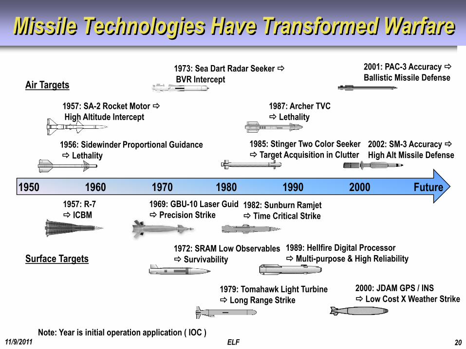
Missile Technologies Have Transformed Warfare
11/9/2011 ELF 20
1950 1960 1970 1980 1990 2000 Future
1969: GBU-10 Laser Guid
Precision Strike
1972: SRAM Low Observables
Survivability
1979: Tomahawk Light Turbine
Long Range Strike
1987: Archer TVC
Lethality
1989: Hellfire Digital Processor
Multi-purpose & High Reliability
2000: JDAM GPS / INS
Low Cost X Weather Strike
2001: PAC-3 Accuracy
Ballistic Missile Defense
1985: Stinger Two Color Seeker
Target Acquisition in Clutter
Note: Year is initial operation application ( IOC )
1982: Sunburn Ramjet
Time Critical Strike
Surface Targets
2002: SM-3 Accuracy
High Alt Missile Defense
1957: R-7
ICBM
1973: Sea Dart Radar Seeker
BVR Intercept
1957: SA-2 Rocket Motor
High Altitude Intercept
1956: Sidewinder Proportional Guidance
Lethality
Air Targets
11/9/2011 ELF 21
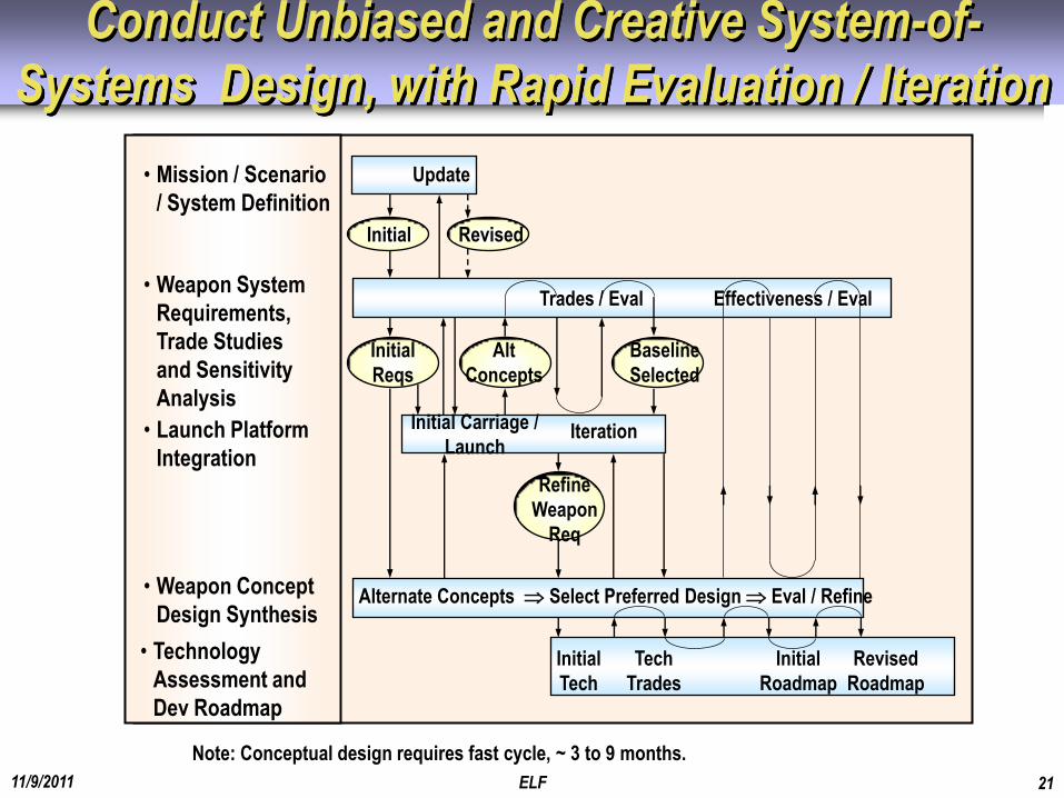
Conduct Unbiased and Creative System-of-
Systems Design, with Rapid Evaluation / Iteration
• Mission / Scenario
/ System Definition
• Weapon System
Requirements,
Trade Studies
and Sensitivity
Analysis
• Launch Platform
Integration
• Weapon Concept
Design Synthesis
• Technology
Assessment and
Dev Roadmap
Initial
Tech
Initial
Reqs
Baseline
Selected
Alt
Concepts
Initial Carriage /
Launch Iteration
Refine
Weapon
Req
Initial Revised
Trades / Eval Effectiveness / Eval
Tech
Trades
Initial
Roadmap
Revised
Roadmap
Update
Note: Conceptual design requires fast cycle, ~ 3 to 9 months.
Alternate Concepts Select Preferred Design Eval / Refine
11/9/2011 ELF 22
Wrap Up ( Part 1 of 2 )
Missile Conceptual Design and System Engineering Is a Creative, Fast, and
Iterative Process that Includes
System requirements flow-down
System integration considerations
Missile concepts and sizing
Technology assessment
Flight trajectory evaluation
Measures of merit evaluation
Cost / Performance / Risk Drivers Are Often “Locked In” During Conceptual
Design
Missile Conceptual Design and System Engineering Is Best Conducted by a
Diverse Group
Military customer mission / scenario definition
Operations analysts system-of-systems modeling
System integration engineers launch platform integration
Missile design engineers missile concept synthesis
Technical specialists technology assessment / technology roadmap
11/9/2011 ELF 23
Wrap Up ( Part 2 )
The Missile Conceptual Design – System Engineering Philosophy Requires
Iteration, iteration, iteration
Evaluation of a broad range of alternatives
Traceable flow-down allocation of requirements
Starting with a good baseline
Pareto sensitivity analysis to determine most important, driving parameters
Awareness of System Engineering Boundaries / Constraints
Synergistic compromise / balanced subsystems and technologies that are high
leverage
11/9/2011 ELF 24
Follow-up Communication
I would appreciate receiving any questions, comments, and
corrections that you may have on this presentation, as well
as any data, photographs, drawings, videos, examples, or
references that you may offer.
Thank you,
Gene Fleeman
Missile Design and System Engineering
E-mail: [email protected]
Web Site: http://genefleeman.home.mindspring.com