Embed Size (px)
Citation preview
ULTRASONIC INSTRUMENTATION SYSTEM FOR DETECTING LIQUEFIED
PETROLEUM GAS LEVEL IN 14 KILOGRAM CYLINDERS
AHMAD „AKIF BIN ADAM
A thesis submitted in fulfilment of the
requirements for the award of the degree of
Master of Engineering (Gas)
Faculty of Petroleum and Renewable Energy Engineering
Universiti Teknologi Malaysia
JUNE 2015

iii
Dedicated to my beloved parent, ummi and abah,
and all my lovely siblings,
thanks for your love and encouragement

iv
ACKNOWLEDGEMENT
First of all, I would like to thank Allah The Almighty for giving me the strength
and opportunity to finish this research study. In completing this project, I was in contact
with many people, researchers, and academicians. They have contributed towards my
understanding and thoughts.
In particular, I wish to express my sincere appreciation to my research supervisor,
Dr. Mariani Idroas, for encouragement, guidance, critics and motivation towards the
completion. Without her continued support and interest, this thesis would not have been
the same as presented here. A remarkable honor to Associate Professor Ir. Dr. Zainal
Zakaria, my co-supervisor, for his knowledge sharing and thoughtful ideas.
My sincere appreciation also extends to all my colleagues especially to Advanced
Microprocessor Research (AMIR) Laboratory members and others who have provided
assistance at various occasions. I am also grateful to all my family members. Their views
and tips are useful indeed. May Allah S.W.T. rewards and blesses us all.

v
ABSTRACT
Liquefied Petroleum Gas (LPG) is commonly stored in highly pressurized cylinder
tank and needs to be measured using a non-invasive way. This approach has been
constructed to facilitate the process of LPG level measurement inside a cylinder tank.
Currently, liquid level of LPG inside a cylinder is measured using a weighing scale. In this
research, a new method is developed by using a non-invasive ultrasonic instrumentation
system for monitoring LPG level in the 14 kilogram cylinder. The instrumentation system
was integrated with the designed experimental rig. Module ultrasonic sensors Truma.LC-
V1.15 were attached vertically outside of the cylinder wall on the sensor holder of the
experimental rig. The ultrasonic sensors emit the ultrasonic signals and the signals will
then propagate through the cylinder wall. The reflected signal was recorded again by the
ultrasonic sensors. The reflection of the ultrasonic signal depends on the type of the
medium's impedance. The generated signals from the transceiver type of sensors were sent
to the Pico Scope Data Acquisition System (DAQ) for data reading. The output voltage
signals were processed by the computational data process system, giving a result of the
LPG liquid level inside the cylinder. An image of the LPG liquid level in the cylinder was
constructed using javascript based programming. The image showed the liquid level in
percentage value and html software was used as the interface in this program. The
developed instrumentation system was also tested on 18-L testing cylinder and 14-kg LPG
cylinder with various LPG liquid levels and it was able to detect the amount of LPG in the
cylinders, with the maximum error of 5.68%.

vi
ABSTRAK
Petroleum Gas Cecair (LPG) biasanya disimpan di dalam silinder bertekanan tinggi
dan perlu diukur dengan cara tanpa musnah. Cara ini telah dibina untuk memudahkan
proses pengukuran aras LPG di dalam tangki silinder. Pada masa kini, aras cecair LPG di
dalam silinder diukur menggunakan alat penimbang berat. Dalam kajian ini, satu kaedah
baru dibangunkan menggunakan sistem peralatan ultrasonik tanpa musnah untuk
memantau aras LPG di dalam silinder simpanan berkapasiti 14 kilogram. Sistem peralatan
ini disepadukan dengan rekaan pelantar eksperimen. Modul deria ultrasonik Truma.LC-
V1.15 telah dipasang pada pemegang sensor pelantar eksperimen. Deria ultrasonik
tersebut dipasangkan secara menegak di luar dinding silinder. Deria ultrasonik
memancarkan isyarat ultrasonik dan isyarat telah tersebar menembusi dinding silinder.
Isyarat pantulan dirakam semula oleh deria ultrasonik. Pantulan isyarat ultrasonik
bergantung kepada jenis galangan bahan perantara. Isyarat yang dihasilkan dari deria jenis
penghantar-terima telah dihantar ke Pico Scope Data Sistem Perolehan (DAQ) untuk
membaca data. Isyarat voltan keluaran diproses oleh sistem proses data perkomputeran
untuk memberikan aras kandungan cecair LPG di dalam silinder. Pembinaan imej aras
LPG dalam silinder dibina menggunakan pengaturcaraan berasaskan javascript. Imej
tersebut menunjukkan imej aras LPG di dalam nilai peratusan dan perisian html digunakan
sebagai perantara muka pada program ini. Sistem peralatan yang dibangunkan diuji pada
18-L silinder ujian dan 14-kg LPG silinder yang berbeza aras cecair LPG dan sistem ini
berjaya mengesan jumlah LPG dalam silinder dengan ralat maksimum 5.68%.
vii
TABLE OF CONTENTS
CHAPTER TITLE PAGE
DECLARATION ii
DEDICATION iii
ACKNOWLEDGEMENT iv
ABSTRACT v
ABSTRAK vi
TABLE OF CONTENTS vii
LIST OF TABLES x
LIST OF FIGURES xi
LIST OF ABBREVIATIONS xiv
LIST OF SYMBOLS xv
LIST OF APPENDICES xvii
1 INTRODUCTION 1
1.1 Project Background
1.2 Problem Statement
1.3 Objective
1.4 Scope of Study
1.5 Thesis Outline
1
4
6
7
7
2 LITERATURE REVIEW 9
2.1 Introduction
2.2 Overview of Liquid Level Measurement
2.3 Types of Liquid Level Measurement
9
9
10

viii
2.4 Liquid Level Measurement
2.5 Use of Ultrasonic in Liquid Level Measurement
2.6 Current Method of LPG Cylinder Measurement
11
12
18
3 METHODOLOGY 19
3.1 Introduction
3.2 Overview of the Instrumentation System
3.3 Instrumentation Rig Configuration
3.3.1 Development of Platform
3.3.2 Development of Sensor Holder
3.4 Cylinder Specification
3.5 Sensoring System Optimization
3.5.1 Transmission and Reflection Effect
3.5.2 Ultrasonic Sensoring System
3.5.3 Arrangement of Ultrasonic Sensors
3.5.4 Image Grid Configuration
3.6 Development of Ultrasonic Instrumentation System
3.6.1 Module Sensor
3.6.2 Pico Scope Data Acquisition System (DAQ)
3.6.3 Computational Data Process
3.6.4 Image Generation
3.7 Experimental Procedures
3.7.1 Initial Testing on 18 L Cylinder
Experimental Procedure
3.7.2 Calibration Testing on 14 kg LPG Cylinder
Experimental Procedure
3.7.3 Measurement of 14 kg Cylinder
Experimental Procedure
19
20
21
23
26
32
36
36
41
42
44
47
48
49
50
51
52
52
53
54

ix
4 RESULTS AND DISCUSSIONS 56
4.1 Introduction
4.2 Sensors Testing and Calibration of 18 L Testing
Cylinder
4.2.1 Level Measurement of the 18 L Cylinder
4.2.2 Calibration Graph of 18 L Cylinder Level
Measurement
4.2.3 Discussions
4.3 Sensors Testing and Calibration of LPG Cylinder 14
kg
4.3.1 Data Collection of LPG Cylinder
Measurement
4.3.2 Calibration Graph of LPG Cylinder Level
Measurement
4.3.3 Discussions
4.4 Experimental Tests on LPG Cylinders
4.4.1 Data of Case 1
4.4.2 Data of Case 2
4.4.3 Data of Case 3
4.4.4 Data of Case 4
4.4.5 Discussions
4.5 Image of LPG Level
56
57
57
64
65
67
67
68
69
71
72
73
74
75
76
77
5 CONCLUSIONS AND RECOMMENDATIONS
5.1 Conclusions
5.2 Recommendations
80
80
81
REFERENCES
Appendices A
83
87-104

x
LIST OF TABLES
TABLE NO. TITLE PAGE
3.1 Specification of both cylinders 35
3.2 Level and percentage fill relation information 47
4.1 Data collection of level measurement at 23.0 cm 58
4.2 Overall data collection of level measurement on testing
cylinder 18 L
63
4.3 Level measurements for the actual level and from indicator
sensor
66
4.4 LPG cylinder 14 kg measurement testing data collection 68
4.5 Table of weight, volume, level and its percentage from
weight measurement
70
4.6 Comparison table of weight measurement and sensor
measurement
70
4.7 Experimental data of empty cylinder (17.0 kg) 72
4.8 Experimental data of partially filled cylinder (21.7 kg) 73
4.9 Experimental data of partially filled cylinder (27.2 kg) 74
4.10 Experimental data of fully filled cylinder (30.5 kg) 75

xi
LIST OF FIGURES
FIGURE NO. TITLE PAGE
1.1 Cylinders with LPG 3
1.2 Manifold LPG system 4
1.3 Weighing measurement of LPG cylinder 6
2.1 The gas cylinder with liquid inside and the mechanical
model of mass density
12
2.2 Block diagram of generation, propagation, and reception
of lamb waves of tank wall
15
2.3 The arrangement of the prototype level sensing using
lamb wave at the tank wall
15
2.4 Measuring level method 17
3.1 Overall setup of ultrasonic instrumentation system 19
3.2 Photo of Ultrasonic instrumentation system 20
3.3 Instrumentation rig diagram 22
3.4 Actual photo of instrumentation rig 22
3.5 Mechanical design of platform (side and top view) 24
3.6 Real image of the platform 24
3.7 Installed wheels and its mechanical design 25
3.8 Stopper and its mechanical design 25
3.9 Platform surface arrangement 26
3.10 Sensor holder 27
3.11 Vertical mounting of sensor on a sensors holder 28
3.12 Actual fabricated sensor holder 28
3.13 Design of sensor with casing 29
3.14 Image of sensor with casing 29

xii
3.15 Mechanical design of stand 30
3.16 Housing base of the instrumentation rig 31
3.17 Connector 31
3.18 Testing cylinder of 18 L capacity 33
3.19 Dimension of testing cylinder 33
3.20 Dimension of LPG cylinder tank 34
3.21 LPG cylinder of 14 kg 35
3.22 Ultrasonic signal transmission and reflection 37
3.23 Illustration on different medium of cylinder content 41
3.24 Sensors arrangement 42
3.25 Sensors touch to the cylinder wall 43
3.26 Photograph of sensor arrangement 44
3.27 Cylinder fraction due to sensor arrangement 45
3.28 Graphical illustration of ellipsoidal bottom cylinder 46
3.29 Process flow of ultrasonic instrumentation system 47
3.30 Ultrasonic Instrumentation system 48
3.31 Ultrasonic Truma.LC-V1.15 module sensor 49
3.32 Pico Scope DAQ 50
3.33 Image of percentage cylinder filling 51
4.1 Voltage signal at sensor 1, S1 = 3.53 V 59
4.2 Voltage signal at sensor 2, S2 = 3.67 V 59
4.3 Voltage signal at sensor 3, S3 = 3.46 V 59
4.4 Voltage signal at sensor 4, S4 = 3.71 V 60
4.5 Voltage signal at sensor 5, S5 = 3.81 V 60
4.6 Voltage signal at sensor 6, S6 = 4.62 V 60
4.7 Voltage signal at sensor 7, S7 = 4.83 V 61
4.8 Voltage signal at sensor 8, S8 = 4.69 V 61
4.9 Voltage signal at sensor 9, S9 = 4.97 V 61
4.10 Voltage signal at sensor 10, S10 = 4.61 V 62
4.11 Graph of output voltage (V) for S1 to S10 at 23.0 cm water
level
62
4.12 Graph of actual water level against measured water levels 64
4.13 Graph of LPG cylinder calibration 69

xiii
4.14 Image interface of Case 1 with 8.14% 77
4.15 Image interface of Case 2 with 35.18% 78
4.16 Image interface of Case 3 with 63.29% 78
4.17 Image interface of Case 4 with 85.36% 79

xiv
LIST OF ABBREVIATIONS
ASTM - American Society for Testing and Materials
CFC - Chloro Fluoro Carbon
DAQ - Data Acquisition System
DC - Direct Current
GMB - Gas Malaysia Berhad
HHV - Higher Heating Value
HTML - Hyper Text Markup Language
LHV - Lower Heating Value
LPG - Liquefied Petroleum Gas
MSDS - Material Safety Data Sheet
NDT - Non Destructive Testing
PC - Personal Computer
PZT - Lead Zirconium Titanate
PVC - Poly Vinyl Chloride
STP - Standard Temperature and Pressure
TOF - Time of Flight
UT - Ultrasonic Testing

xv
LIST OF SYMBOLS
π - Pi, 3.14
ρ - Density
a - Depth of Head or Bottom
θ - Angle
atm - Atmospheric Pressure
avg - Average
c - Speed of Light
cm - Centimeter
D - Diameter
g - Gram
h - Height of Liquid Level
kg - Kilogram
J - Joule
kHz - Kilohertz
L - Length
m - Meter
mm - Millimeter
MHz - Megahertz
MJ - Megajoule
r - Radius
R - Reflection Coefficient
Rayl - Rayleigh
S - Sensor Number
t - Time
T - Transmission Coefficient
xvi
V - Voltage
υ - Volume
W - Weight
Z - Acoustic Impedence
° - Degree
°C - Degree Celcius
°F - Degree Fahrenheit
E - Wave Energy
S - Sensor
T - Transmitter
C3H8 - Propane
C4H10 - Butane
% e - Percentage of Error

xvii
LIST OF APPENDICES
APPENDIX TITLE PAGE
A Technical Drawing of Ultrasonic Instrumentation Rig 87

CHAPTER 1
INTRODUCTION
1.1 Project Background
Oil and gas are natural resources that contribute as the source of fuel to most of the
countries in the world for its economic expansion. Many nations depend on these natural
resources for growth and development of their countries. It is necessary to ensure that the
natural resources can be transported safely from its original plant or storage to the
consumers throughout the countries (Bannon, 2003).
The transmission process and storage technique of oil and gas must be in control
because of its natural characteristic that is highly volatile and flammable. There are many
methods used to transfer these oil and gas supply to the market such as tanker, pipeline
barge, rail and truck.
Liquefied petroleum gas (abbreviated as LPG) is a chemical compound that usually
used as a fuel for cooking, combusting and burning tool and also used for transportation
energy source. This inflammable mixture is widely used as an aerosol propellant and a

2
refrigerant. The LPG replaced CFC in an effort to reduce the effect of green house and
protect the ozone layer (Bejan, 1999).
There are various types of LPG mixture available in the market and the mixture of
their composition are different for each country and depend on the seasonal weather of the
country. There will be more propane in winter while more butane in summer (Totten,
2003). There are types of mixes which are mainly propane (C3H8), and mainly butane
(C4H10). The mostly common mixes were the mixture of both propane and butane in a
certain percentage.
Substance of propylene and butylenes are normally present but in a little
concentration. LPG is basically in gas or liquid phase which is odourless and colourless.
Therefore, it is difficult to detect whether there are any existence of LPG or not. The
odorant like ethanethiol, is incorporated with LPG so that leaks can be recognize easily. In
the United States, thiophene known also as amyl mercaptan is an approved odorants
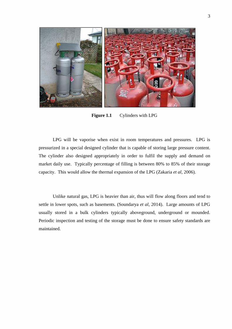
(Mahalingam, 2012). Figure 1.1 shows the example of LPG cylinders commonly used
today.
3
Figure 1.1 Cylinders with LPG
LPG will be vaporise when exist in room temperatures and pressures. LPG is
pressurized in a special designed cylinder that is capable of storing large pressure content.
The cylinder also designed appropriately in order to fulfil the supply and demand on
market daily use. Typically percentage of filling is between 80% to 85% of their storage
capacity. This would allow the thermal expansion of the LPG (Zakaria et al, 2006).
Unlike natural gas, LPG is heavier than air, thus will flow along floors and tend to
settle in lower spots, such as basements. (Soundarya et al, 2014). Large amounts of LPG
usually stored in a bulk cylinders typically aboveground, underground or mounded.
Periodic inspection and testing of the storage must be done to ensure safety standards are
maintained.

4
1.2 Problem Statement
Liquefied Petroleum Gas (LPG) becomes the most popular source for household
and commercial uses. Basically, when compared to other liquid fuels, LPG is flexible to
handle and having lesser pollution with minimum space used for storage. LPG will be
delivered to the customer either by using cylinder, bulk tank or pipeline. There are several
ways of LPG distribution to customers depends on the type of customer i.e. whether it is
domestic, commercial or industry. Figure 1.2 shows an example of manifold LPG system
installation for commercial use.
Figure 1.2 Manifold LPG system (Primagas, 2009)
LPG consumption for every customers were different depending on the rate of use.
There were consumers who used LPG daily at a high rate such as the laundries that uses
for the purpose of drying clothes. Numbers of users only use a small amount of LPG for
home cooking. The different on LPG consumption rate of consumers carries variation of
usage among consumer thus requiring friendly LPG cylinder measurement. This idea was
not as important for some consumers, but it was very significant for customers who
utilized the LPG on a large scale basis especially for those who use it for commercial
purposes.

5
Therefore, this research study is intended to develop an ultrasonic instrumentation
system to measure the LPG residual in the cylinder in a better way using ultrasonic
sensors. This study focused on the ability of the developed system in monitoring the
presence of LPG and its level. This is the initial study to detect the LPG level imposed on
the household LPG cylinders of a 14 kg capacity.
Most of LPG users, especially among commercial and industrial field were used
weighing instrument in order to obtain the exact contents of LPG inside the cylinder.
Some of them measured the amounts of LPG inside the cylinder by checking the content
pressure. This method was often used by the refilling plant because this is the fastest way
of measurement. This pressure type measurement was conducted in a rapid process
because the filling process and the pressure readings were taken simultaneously. Figure
1.3 shows the example of weighing instrument for LPG cylinder. This machine was
designed completed with the gas filler tool for LPG refilling process.
Figure 1.3 Weighing measurement of LPG cylinder (Siraga, 2008)
6
Ultrasonic instrumental technique was an acceptable way to monitor the LPG
content in the LPG cylinder. This method is proposed because it can help the process of
measurement in easy way using non-invasive procedure.
1.3 Objectives
The objectives of this project are:
i. To develop a non-invasive ultrasonic instrumentation system for detecting
the LPG content in LPG cylinder storage.
ii. To monitor LPG residual inside the cylinder.
1.4 Scopes of Study
In order to achieve the objectives of this project, the scopes are:
i. Understanding the principal of ultrasonic measuring method on liquid level
measurement.
ii. Development of instrumentation rig of LPG cylinder measurement.
iii. Performing the study on sensoring system optimization
iv. Setting up the ultrasonic instrumentation system including module sensor,
Pico Scope DAQ, computational data process and image reconstruction.

7
v. Carry out preliminary experiment on testing cylinder 18L and LPG cylinder of
14 kg for instrumentation system calibration and accomplish the experimental
measurement on four different types of LPG cylinder.
vi. Analyzing data receive from Pico Scope DAQ using computational data
process system.
vii. Generating the percentage of LPG content information using html based
programming.
1.5 Thesis Outline
Chapter 1 briefly presents the background information about oil and gas industry
around the world. LPG is one of oil and gas product which is essential in our daily needs
for household use, industry and transportation. LPG characteristics, transmission and
storage system have been briefly defined. This chapter includes the problem statement,
objectives and the scopes of the project. Chapter 2 explains the literature review about the
measurement of LPG storage on recent industrial usage. The configuration systems of
measurement and the suitable type of sensors are described in more detailed. Chapter 3
describes the methodology on LPG instrumentation system based on ultrasonic sensors to
detect the LPG level. The outcome signals are explained to show the LPG level in suitable
image. Chapter 4 presents results obtained from the experiments. Specific justifications
and explanations about the output results are explained to validate and verify the
correctness of the experiment. Chapter 5 combines the overall conclusions and some of
recommendations for future improvements.

REFERENCES
Bannon, I. and Collier, P. (2003). Natural resources and violent conflict: options and
actions, World Bank.
Bejan, A., Vadász, P. and Kröger, D. G. (1999). Energy and the environment: Kluwer.
Hisham, C. B. (1994). Pengukuran Secara Kualitatif Baki Gas Petroleum Cecair.
Universiti Teknologi Malaysia: Tesis Sarjana Muda.
Chan, K. T. and Zhang, J. Z. (1995). Free vibration of a cantilever tube partially filled with
liquid. Journal of Sound and Vibration. 182, 185-190.
Cheeke, J. D. N. (2012). Fundamentals and Applications of Ultrasonic Waves, (2nd
ed.).
Taylor & Francis.
Desoutter, D. M. (1971). Your Book of Sound, Faber.
Elvers, B. (2008). Handbook of fuels: energy sources for transportation. Wiley-VCH.
Hao, H.H.,and Xiong, J.Q. (2010). A Method of Liquid Level Measurement Based on
Ultrasonic Echo Characteristics, Computer Application and System Modeling
(ICCASM), 2010 International Conference. Vol.11.22-24 Oct. 682-684.
Hofer, M. (2005). Ultrasound Teaching Manual: the Basics of Performing and
Interpreting Ultrasound Scans, Thieme.
Iain, S. (2011). The Energy and Fuel Data Sheet. University of Birmingham, United
Kingdom.
Jones, D. (2003) Calculating Tank Volume Saving Time, Increasing Accuracy. P.P.1-12.
Juvanna, I. and Meenakshi, N. (2014) Gas Level Detection and Leakage Monitoring
System using a Specific Technique, Journal of Computer Science and Information
Technology, IJCSMC, Vol. 3, Issue. 2, February 2014, pg.591 – 595.
Kennedy, J. L. (1993). Oil and gas pipeline fundamentals: PennWell Books.
84
Licznerski, T. J., Jaroński, J., Kosz, D. (2011). Ultrasonic system for accurate distance
measurement in the air. Ultrasonics 51(8): 960-965.
Mahalingam, A., Naayagi, R. T., Mastorakis, N. E. (2011). Design and Implementation of
an Economic Gas Leakage Detector. Recent Researches in Applications of
Electrical and Computer Engineering. P.P. 20-24.
Meribout, M., Habli, M., Al-Naamany, A., Al-Busaidi, K. (2004). A New Ultrasonic-
Based Device for Accurate Measurement of Oil, Emulsion, and Water Levels in Oil
Tanks, Instrumentation and Measurement Technology Conference, 2004. IMTC 04.
Proceedings of the 21st IEEE, 18-20 May 2004, Vol.3, 1942-1947.
Meyer, W. J. (2004). Concepts of Mathematical Modeling: Dover Publications.
Meenakshi, P. V., Abinaya, S., Rajeswari, G.G., Guna, N. (2014). Automatic LPG Leakage
Detection and Hazard Prevention for Home Security. Proceeding of 5th National
Conference on VLSI, Embedded, and Communication & Networks on April 17,
2014.1-5.
Mogami, K., Saito, S., Makishita, H.Ando, K. Ogura, N, (1986). Failure Analysis of a
Liquid Propane Gas Cylinder Analyzing Failures: The Problems and the Solutions.
2-6 Dec. 1985. Salt Lake City; Utah, USA, pp. 75-80.
Morris, A. S. and Langari, R. (2012). Measurement and Instrumentation: Theory and
Application: Academic Press.
Oxenham, M. (2013). Higher Education in Liquid Modernity: Taylor & Francis.
Onda, C., (2003). Acoustic Properties of Liquids, Gases and Solids :Onda Corporation.
Petrauskas, A. (2008) Experimental determination of sound velocity in liquefied propane-
butane gas mixture (LPG), Ultragarsas (Ultrasound), Vol. 63, No. 3.
Priya, K. P., Surekha, M., Preethi, R., Devika, T., Dhivya, N. (2014). Smart Gas Cylinder
Using Embedded System. International Journal Of Innovative Research In
Electrical, Electronics, Instrumentation And Control Engineering, Vol. 2, Issue
2,958-962.
Raj, B., Jayakumar, T. and Thavasimuthu, M. (2002). Practical non Destructive Testing:
Woodhead.
Saad, F. F. M. (2009) The Design And Development Of Warning Device For Low Pressure
LPG Tank. Universiti Teknikal Malaysia.
Sakharov, V. E., S. A. Kuznetsov, S.A., Zaitsev, B.D., Kuznetsova, I.E., Joshi, S.G.
(2003). Liquid level sensor using ultrasonic Lamb waves. Ultrasonics 41(4): 319-
322.

85
Shih, H., C. and H. H. P. Wu (2010). Liquid level detection of the sealed gas tank based on
digital signal processing. Image and Signal Processing (CISP), 2010 3rd
International Congress.
Singh, S. K. 2003. Industrial Instrumentation & Control,2e, McGraw-Hill Education
(India) Pvt Limited.
Singh, H.K., Chakroborty, S.K.,Talukdar, H., Singh, N.M., Bezboruah, T. (2011) A New
Non-Intrusive Optical Technique to Measure Transparent Liquid Level and
Volume, Sensors Journal, IEEE. Vol.11, no.2, pp.391-398.
Singh, H.K., Meitei, N.C., Sarkar, S.T., Tiwari, D., Bezboruah, T., (2013) Truly
Nonintrusive Liquid-Level-Sensing Method Based on Lateral Displacement Effect
of Light Rays. Sensors Journal, IEEE , vol.13, no.2, pp.801-806.
Soundarya, T., Anchitaalagammai, J.V., Priya G. D., Kumar, S.S. K (2014). IOSR Journal
of Electronics and Communication Engineering (IOSR-JECE) Volume 9, Issue 1,
Ver. VI, PP 53-58.
Totten, G. E., Westbrook, S. R., Shah, R. J. (2003). Fuels and Lubricants Handbook:
Technology, Properties, Performance, and Testing: ASTM International.
Torbay Council (2001) Liquefied Petroleum Gas (LPG) Safe Working Practices 3 L 04 -
Page 1-4.
Vesovic, V. (2007) The influence of ice formation on vaporization of LNG on water
surfaces. Journal of Hazardous Materials, 140, pp. 518–526.
Yogeesh, A., Ashwini, Shruthi, B. (2013). Automated Unified System For LPG Refill
Booking & Leakage Detection: A Pervasive Approach. International Journal of
Advanced Technology & Engineering Research (IJATER), Volume 3, Issue 3, 69-
73.
Wang, T.-H., Lu, M.-C., Hsu, C.-C., Chen, C.-C., Tan, J.-D. (2009). Liquid-Level
Measurement Using a Single Digital Camera. Measurement, 42, 604-610.
Zakaria, Z. and Mustafa, A. (2005) Investigation of temperature profile for liquefied
petroleum gas storage operations. 2nd International Conference on Chemical and
Bioprocess Engineering in conjunction with 19th Symposium of Malaysian
Chemical Engineers (SOMChE 2005), 8-10 December 2005, Kota Kinabalu,
Sabah.
Zakaria, Z., Mat, H. and Yusoff, Z. (2006) Heat and Mass Transfer Studies in Liquefied
Petroleum Gas Storage Operations. Project Report. Faculty of Chemical and
Natural Resources Engineering, Skudai, Johor.
86
Zakaria, Z., Mustafa, A. (2011) The Influence Of Compositions On Liquefied Petroleum
Gas Residue In Storage. International Journal of Research and Reviews in Applied
Sciences. 7 (4) 360-367.
Zakaria, Z., Mustafa, A. (2013) The Effect of Filling Weights to Liquefied Petroleum Gas
Residue in Storage. International Journal of Engineering, Business and Enterprise
Applications (IJEBEA). 4 (1), March-May, 2013, pp. 35-43.