Embed Size (px)
Citation preview

06.01.2017www.broekema.nl 0-0
Agricultural Technology
Delivery Program
Crop conveyor belts,
Transport and sorting systems,
Rubber and synthetic components for the
agricultural machinery industry

Contents
06.01.2017www.broekema.nl 0-1
Introduction
This is the first catalogue integrating the product lines of the three Jäger-Group companies
Artemis Kautschuk- und Kunststoff-Technik GmbH, Hannover, Germany,
EA Broekema BV, Veendam, The Netherlands,
Broekema Beltway USA Inc., Pine City, Minnesota, USA,
which all make conveyor belts and components for agricultural machines.
The catalogue is available in 6 languages: English, French, Italian, Spanish, Dutch and German.
The indexed, loose leaf page system will help to simplify later updating.
This catalogue is designed to assist our customers in designing their increasingly more complex conveyor belt & drive variations.Please contact us if your problem does not seem represented, since by receiving problem solving inquiries new products are oftencreated.
All three Companies have state-of-the-art manufacturing facilities under an overall ISO 9001 quality control policy, which assuresconsistency in production & supply from any of our factories.
We continually invest in the development of new products for the agricultural industry and in the improvement of our manufacturingtechnology to maintain a position of quality- and cost-leadership in the marketplace.
All manufacturers are assured of high volume quality, delivered to their needs with the highest levels of operational life, planningconfidence & advice confidentiality.
All three Companies have helped to pioneer the belted system for root crop harvesting & in-store needs, also for nuts, fruit & fish,pre & post grading, washing & drying, etc.. Product and product size may vary from beet to cocktail onions, with ‘treat like eggs’damage protection levels achieved by our conveyor components.
Thank for the many years of support. We intend serving you even better in the future.

Contents
06.01.2017www.broekema.nl 0-2
EA Broekema BV
Box 709640 AB VeendamNiederlandeDe Zwaaikom 19641 KV VeendamNiederlande
Tel.:Fax:E-Mail:Website:
Broekema Beltway USA, Inc
1108 Holstein Drive N.E.Pine City, Minnesota 55063USA
Phone:Phone:Fax:E-Mail:Website:
toll free North America: (800) 654-2711+1 (320) 629-3900+1 (320) [email protected]
Broekema Beltway California
460 N. Pioneer Ave. Ste. 100Woodland, CA 95776USA
Phone:Fax:E-Mail:Website:
+1 (530) 668-8500+1 (530) [email protected]
Artemis Kautschuk- und Kunststoff-Technik GmbH
Rothwiese 430559 Hannover (Anderten)DeutschlandPostfach 73 04 5130553 HannoverDeutschland
Tel.:Fax:E-Mail:Website:
+49.511.95928-0+49.511.95928-55info@artemis-kautschuk.dewww.artemis-kautschuk.de
Windgassen GmbH
Einsteinstr. 533104 PaderbornDeutschland
Tel.:Fax:E-Mail:Website:
+49.5254.990930+49.5254.990939info@wg-siebketten.dewww.wg-siebketten.de

Contents
06.01.2017www.broekema.nl 0-3
Crop conveyor belts 1
Traction belting 2
Belt joints & joining clips 3
Centre belt construction 4
Rivet rods 5
Vulcanised rods 6
Rod coverings 7
Flights 8
Sprockets 9
Rollers 10
Rivets & plates 11
Moulded articles 12
Spare parts 13

Crop conveyor belts
06.01.2017www.broekema.nl 1-0
General information 1- 1

Crop conveyor belts
06.01.2017www.broekema.nl 1-1
General information
Our crop conveyor belts are generally made as follows:
– The round steel rod is cut to length according to the conveyor width, the rod ends are heated, forged/flattened & rivet holespunched at the ends.
– Rivet retaining plates are placed between the traction belt’s underside profile and rivets inserted into plates & belting.– Rods are then fitted onto rivets, whose length relates to rod diameter/forged thickness.– These components are then riveted into a consistent compression package, the rivet head is absorbed into the countersunk
retaining plate and a smooth head formed over the rod’s counter sunk upper surface.
Conveyor assemblies are manufactured to order by overall width & length, using traction belting pitches & widths standards (seechapter 2, traction belting). Options relating to steel rod diameter, rod convexity, cranking etc. see Chapter 5, rivet rods.
Joining clips, lapjoint or endless vulcanization are commonly used to join the ends of a belt (see chapter 3, belt joints & joining clips).
There are multiple rods covering options (see chapter 6 and 7 rod coverings).
If no sprocket run clear ways are required (e.g. friction or cam drives), the rod covering is retained from side movement by thetraction belting, the internal diameter may then be the same or oversize to that of the rod.
Sprocket tooth driven conveyors require tooth clear ways. A slightly undersized (friction fit) rod covering is used. Alternatively acovering may be glued-on/bonded or fully vulcanized to the rod.
Conveyors for crop elevation (see chapter 7, flights) are often fitted with flights/risers applied to the rods at the desired rod/pitchinterval. Optionally, the rods between such flights may be straight or cranked. Such rods increase the effective flight height (seechapter 5, rivet rods). Alternatively a low profile ‘rod pocket system ‘ is possible using a sequence of down & straight or up crankedrods.
We also create special conveyors (see chapter 5, rivet rods):
– Porcupine/pintle rod profiles for trash extraction– Twin-rod system for small rod gap applications– Rods of fibreglass, aluminium or stainless steel for light weight/salt water applications– Square mesh type work surface for special crops & sizing– Conveyors for sorting/grading/dewatering

Traction belting
06.01.2017www.broekema.nl 2-0
General information 2- 1
Technical details 2- 2
EN-Low profile, type 900 2- 3
EN-Low profile, type 1200 2- 4
EN-High profile, type 900 2- 5
EN-High profile, type 1200 2- 6
DN-Low profile, type 900 2- 7
DN-Low profile, type 1200 2- 8
DN-High profile, type 900 2- 9
DN-High profile, type 1200 2-10
EN-High profile parabolic, type 1200/3 2-11
DN-High profile parabolic, type 511.5/3 2-12
DN-High profile, type 900 notched 2-13
EN-High profile, type 630/2 2-14
EN-Low profile, type 900 (Hydro belt) 2-15
EN-High profile, type 900 (Hydro belt) 2-16
EN-Low profile, type 900 (Solar Belt) 2-17
EN-High profile, type 900 (Solar Belt) 2-18
Non profile belting., EP 630/3 2-19
EN-High profile, type EP 1000/2(foodgrade)
2-20
EN-Low profile, type EP 1000/2(foodgrade)
2-21

Traction belting
06.01.2017www.broekema.nl 2-1
General information
Traction belting generally consists of 3 layers of fabric reinforcement, compression-vulcanized between layers of high wear andweather resistance rubber. Belting is available cut to length or at maximum length of 100 meters.
Our traction belting is especially designed for the requirements of harvesting applications featuring::
– High tensile strength– High traction power capacity– High rubber tear resistance– Weather compatibility of the rubber compounds– High drive cam or rod pitch accuracy with good shock load absorption and recovery
3 layers of TN 900/3 type textile forms our ‘Standard’ belting, which offers 900 N (1984 pounds) load strain per cm of belt width(900 N/mm). Such ‘Standard’ belting is normally used in all but the most extreme applications.
The following belting types are especially developed for high-load applications:
– 3 layers of TN 1200/3 fabric offers 1200 N/mm (2650 pounds/cm)– 4 layers of TN 1600/4 fabric offers 1600 N/mm (3537 pounds/cm)
Deduct 10-12 mm from overall belt width due to rivet hole punching when calculating total load strain capacity.
Load strain capacity also relates to guidelines per joint type.
The equipment’s transmission must have a drive clutch protection to prevent over loading to the conveyors joints.
Each belt profile type relates directly to the drive type (see chapter 8, drive systems and sprockets). Belting with an upper profile(double profile belting) recesses the rod ends, reducing crop damage and rivet head wear. Furthermore this guarantees a smootherrunning of the conveyor. Subject to rod diameter which influences overall rod end thickness, return/carry back rollers may be lowercost metal surface type.
‘Hydrobelt’ is especially manufactured for partial or total water submersion applications. It totally encloses the reinforcement carcass,to reduce working environment water or additive absorption, which may otherwise reduce the conveyor’s potential work life.
'Solar Belt' is a product line of traction belting, resistant to Ozone (and UV) with modified recipes of the rubber covers to betterwithstand the degrading influence of Ozone and UV. Solar Belt has been developed for exterior applications in area's with regularelevated Ozone concentrations. Testing according to DIN Standards has proven Solar Belt to show approximately 10% or less of thedegradations due to the influence of Ozone, compared to competitive products.
Traction belting
06.01.2017www.broekema.nl 2-2
Technical details of the standard traction belts
Construction: Tensile strength:TN630/2 630 N/mmTN900/3 900 N/mmTN1200/3 1.200 N/mmTN1600/4 1.600 N/mmRubber hardness: 60 ± 5 Shore APitch tolerance: ± 0,4%Tolerance beltwidth: ± 1 mmRubber (Abrasion):DIN53516
= 130 mm³
Moisture absorption: = 0,5%
Technical details Hydrobelt-type:
Construction:Hydrobelt-type
Tensile strength900 N/mm
Breaking elongation 14% – 18%Rubber hardness 60 + / 5° Shore APitch tolerance ± 0,4%Tolerance beltwidth: ± 1 mmRubber (Abrasion):: < 110 mm³Moisture absorption: none

Traction belting
06.01.2017www.broekema.nl 2-3
EN-Low profile, type 900
Description Opt
ion
al PitchT
[mm]
Tooth widthZB1
[mm]
Recess widthNB1
[mm]
Profile heightZH1
[mm]
* 20 5 15 3
EN 200300 22,5 7,5 15 3
EN 250300 * 25 5 20 3
EN 280300 28 10 18 3
EN 320300 32 14 18 3
EN 330300 33 15 18 3
EN 360300 36 16 20 3
EN 370300 * 37 17 20 3
EN 400300 40 20 20 3
EN 420300 42 22 20 3
EN 430300 * 43 23 20 3
EN 440300 * 44 24 20 3
EN 450300 45 25 20 3
EN 500300 50 30 20 3
EN 560300 * 56 31 25 3
EN 600300 * 60 35 25 3

Traction belting
06.01.2017www.broekema.nl 2-4
EN-Low profile, type 1200
Description Opt
ion
al PitchT
[mm]
Tooth widthZB1
[mm]
Recess widthNB1
[mm]
Profile heightZH1
[mm]
* 20 5 15 3
EN 200300 * 22,5 7,5 15 3
EN 250300 * 25 5 20 3
EN 280300 * 28 10 18 3
EN 280300 * 28 12 16 3
EN 320300 * 32 14 18 3
EN 320300 * 32 16 16 3
EN 330300 * 33 15 18 3
EN 360300 * 36 16 20 3
EN 360300 * 36 20 16 3
EN 370300 * 37 17 20 3
EN 400300 * 40 20 20 3
EN 420300 * 42 22 20 3
EN 420300 * 42 26 16 3
EN 430300 * 43 23 20 3
EN 450300 * 45 25 20 3
EN 480300 * 48 32 16 3
EN 500300 * 50 30 20 3
EN 560300 * 56 31 25 3
EN 600300 * 60 35 25 3

Traction belting
06.01.2017www.broekema.nl 2-5
EN-High profile, type 900
Description Opt
ion
al PitchT
[mm]
Tooth widthZB1
[mm]
Recess widthNB1
[mm]
Profile heightZH1
[mm]
EN 280900 28 9 14 9,5
EN 300900 * 30 10,3 15 9,5
EN 350900 35 15,3 15 9,5
EN 400900 40 16,3 19 9,5
EN 430900 * 43 16,2 21,5 9,5
EN 440900 44 17,1 21,5 9,5
EN 500900 50 19,7 25 9,5
EN 600900 * 60 27,5 27 9,5

Traction belting
06.01.2017www.broekema.nl 2-6
EN-High profile, type 1200
Description Opt
ion
al PitchT
[mm]
Tooth widthZB1
[mm]
Recess widthNB1
[mm]
Profile heightZH1
[mm]
EN 350900 * 35 15,3 15 9,5
EN 400900 40 16,3 19 9,5
EN 430900 * 43 16,2 21,5 9,5
EN 440900 * 44 17,1 21,5 9,5
EN 500900 50 19,7 25 9,5
EN 600900 * 60 27,5 27 9,5

Traction belting
06.01.2017www.broekema.nl 2-7
DN-Low profile, type 900
T50 + 60 grooved
Description Opt
ion
al PitchT
[mm]
Tooth widthZB1
[mm]
Tooth widthZB2
[mm]
Recess widthNB1
[mm]
Recess widthNB2
[mm]
Profile heightZH1
[mm]
Profile heightZH2
[mm]
DN 280309 * 28 10 7 18 21 3 9
DN 320309 32 14 11 18 21 3 9
DN 360309 36 16 10 20 26 3 9
DN 400309 40 20 14 20 26 3 9
DN 420309 42 22 16 20 26 3 9
DN 450309 45 25 19 20 26 3 9
DN 500309 * 50 30 25 20 25 3 9
DN 600309 * 60 35 35 25 25 3 9

Traction belting
06.01.2017www.broekema.nl 2-8
DN-Low profile, type 1200
T50 + 60 grooved
Description Opt
ion
al PitchT
[mm]
Tooth widthZB1
[mm]
Tooth widthZB2
[mm]
Recess widthNB1
[mm]
Recess widthNB2
[mm]
Profile heightZH1
[mm]
Profile heightZH2
[mm]
DN 320309 * 32 14 11 18 21 3 9
DN 360309 * 36 16 10 20 26 3 9
DN 400309 * 40 20 14 20 26 3 9
DN 420309 * 42 22 16 20 26 3 9
DN 450309 * 45 25 19 20 26 3 9
DN 500309 50 30 25 20 25 3 9
DN 600309 60 35 35 25 25 3 9

Traction belting
06.01.2017www.broekema.nl 2-9
DN-High profile, type 900
T50 + 60 grooved
Description Opt
ion
al PitchT
[mm]
Tooth widthZB1
[mm]
Tooth widthZB2
[mm]
Recess widthNB1
[mm]
Recess widthNB2
[mm]
Profile heightZH1
[mm]
Profile heightZH2
[mm]
DN 280909 * 28 8 7 15 20 9,5 9
DN 350909 35 15,3 14 15 21,5 9,5 9
DN 400909 40 16,3 14 19 26 9,5 9
DN 430909 * 43 16,2 18 21,5 26 9,5 9
DN 440909 44 17,1 18 21,5 26 9,5 9
DN 500909 * 50 19,7 25 25 25 9,5 9
DN 600907 * 60 27,5 33 27 27 9,5 7,5
DN 600909 * 60 27,5 33 27 27 9,5 9

Traction belting
06.01.2017www.broekema.nl 2-10
DN-High profile, type 1200
Description Opt
ion
al PitchT
[mm]
Tooth widthZB1
[mm]
Tooth widthZB2
[mm]
Recess widthNB1
[mm]
Recess widthNB2
[mm]
Profile heightZH1
[mm]
Profile heightZH2
[mm]
DN 350907 35 15,3 13,5 15 21,5 9,5 7,5
DN 400907 40 16,3 18,5 19 21,5 9,5 7,5
DN 430907 * 43 16,2 18 21,5 25 9,5 7,5
DN 440907 * 44 17,1 22,5 21,5 21,5 9,5 7,5
DN 490907 49,5 19,2 24,5 25 25 9,5 7,5
DN 500907 50 19,7 25 25 25 9,5 7,5
DN 600907 * 60 27,5 33 27 27 9,5 7,5

Traction belting
06.01.2017www.broekema.nl 2-11
EN-High profile parabolic, type 1200/3
Description Opt
ion
al PitchT
[mm]
Tooth widthZB1
[mm]
Recess widthNB1
[mm]
Profile heightZH1
[mm]
WidthB
[mm]
EN 501200P * 50 19 24,5 12 60

Traction belting
06.01.2017www.broekema.nl 2-12
DN-High profile parabolic, type 511.5/3
T50 + 60 grooved
Description Opt
ion
al PitchT
[mm]
Tooth widthZB1
[mm]
Tooth widthZB2
[mm]
Recess widthNB1
[mm]
Recess widthNB2
[mm]
Profile heightZH1
[mm]
Profile heightZH2
[mm]
DN 401209P * 40 14,5 15 19 25 12 9
DN 501209P * 50 19 25 24,5 25,5 12 9
DN 601209P * 60 24 35 29,5 25 12 9

Traction belting
06.01.2017www.broekema.nl 2-13
DN-High profile, type 900 notched
Description Opt
ion
al PitchT
[mm]
Tooth widthZB1
[mm]
Tooth widthZB2
[mm]
Recess widthNB1
[mm]
Recess widthNB2
[mm]
Profile heightZH1
[mm]
Profile heightZH2
[mm]
G 320505 * 32 13 14 15 18 8 8
G 350505 35 16 14,7 15 18,5 8 8
G 400505 40 17,3 18,6 19 19,5 8 8
G 440505 44 16 24,5 24 19,5 8 8
G 450505 * 45 16,7 23,5 24 19,5 8 8
G 500505 50 16 28,6 30 19,5 8 8

Traction belting
09.01.2017www.broekema.nl 2-14
EN-High profile, type 630/2
Description Opt
ion
al PitchT
[mm]
Tooth widthZB1
[mm]
Recess widthNB1
[mm]
Profile heightZH1
[mm]
EN 280900 28 9 14 9,5

Traction belting
06.01.2017www.broekema.nl 2-15
EN-Low profile, type 900 (Hydro belt)
Description Opt
ion
al PitchT
[mm]
Tooth widthZB1
[mm]
Recess widthNB1
[mm]
Profile heightZH1
[mm]
EN 280300 * 28 10 18 3
EN 320300 * 32 14 18 3
EN 360300 * 36 16 20 3
EN 400300 * 40 20 20 3

Traction belting
06.01.2017www.broekema.nl 2-17
EN-Low profile, type 900 (Solar Belt)
Description Opt
ion
al PitchT
[mm]
Tooth widthZB1
[mm]
Recess widthNB1
[mm]
Profile heightZH1
[mm]
EN 280300 * 28 10 18 3
EN 320300 * 32 14 18 3
EN 360300 * 36 16 20 3
EN 420300 * 42 22 20 3
EN 450300 * 45 25 20 3
EN 500300 * 50 30 20 3
EN 560300 * 56 31 25 3

Traction belting
06.01.2017www.broekema.nl 2-18
EN-High profile, type 900 (Solar Belt)
Description Opt
ion
al PitchT
[mm]
Tooth widthZB1
[mm]
Recess widthNB1
[mm]
Profile heightZH1
[mm]
EN 350900 * 35 15,3 15 9,5
EN 400900 * 40 16,3 19 9,5

Traction belting
06.01.2017www.broekema.nl 2-19
Non profile belting., EP 630/3Belting width 60, to be cut back to 20, 30, 40, 50 mm
Description Opt
ion
al PitchT
[mm]
Belt thicknessBD
[mm]
Non profile belt All pitches 7

Traction belting
09.01.2017www.broekema.nl 2-20
EN-High profile, type EP 1000/2 (foodgrade)
Description Opt
ion
al PitchT
[mm]
Tooth widthZB1
[mm]
Recess widthNB1
[mm]
Profile heightZH1
[mm]
WidthB
[mm]
EN 280900 28 9 14 9 60
EN 350900 36 15,3 15 9 60

Traction belting
09.01.2017www.broekema.nl 2-21
EN-Low profile, type EP 1000/2 (foodgrade)
Description Opt
ion
al PitchT
[mm]
Tooth widthZB1
[mm]
Recess widthNB1
[mm]
Profile heightZH1
[mm]
WidthB
[mm]
EN 280300 28 10 18 3 60
EN 360300 36 16 20 3 60

Belt joints & joining clips
06.01.2017www.broekema.nl 3-0
General information 3- 1
Endless vulcanised joint 3- 2
Lapjoints 3- 3
Joining clips, type AB 3- 4
Joining clips, type AF 3- 5
Joining clips, type BC 3- 6
Joining clips, type E 3- 7
Joining clips, type G 3- 8
Joining clips, type LW 3- 9
Joining clips, type LW 3-10
Double Pivot, joining 3-11
Joining clips, type GAB 3-12
Joining clips, type GABL 3-13
Joining clips, type BS 3-14
Joining clips, type BSV 3-15

Belt joints & joining clips
06.01.2017www.broekema.nl 3-1
General information
Three basic types of belt joints are offered, listed here in order of increasing joint strength:
– Hardened joining clips: Riveted to the belting and linked via a connector rod.– Lapjoint: Layered over several pitches, the belt ends may consist of two or three layering steps. The ends are secured with
screws and bolts. Please ask about our overlap joint options, which can include the use of threaded plates rather than nutsand bolts.
– Endlessly vulcanized joint: After the ends have been layered over several pitches, this type of joint offers the greatest degreeof strength and flexibility.
For reverse drive systems or ‘S’ drives and their end rollers double-pivot belt connectors are required: A metal (pitch related)extension piece is fitted between two female joining clips, using two joining rods, to offer a flexible and smooth running of thedouble pivot joint over drive elements.
This metal link can also be used as a length extension repair piece, if the joining clip of one traction belting tears out.
To increase operational reliability keep the following points in mind:
– The tear-out resistance of any joint remains the conveyor’s weakest point!– Any conveyor’s drive must include an overload slip clutch to help prevent joint tear out.– Use largest drive wheel option and reduce crop fall damage by means of a good rod covering.– A tightly run conveyor increases rod, belt and joint stress, therefore more rapid wear.– If tear-out is experienced, a good belt slack allows the fitting of a new joining clip on the next good belt pitch, without
creating undue belt tension.– Routinely check good support roller rotation to avoid undue belt stress.– Allow for good belt slackness in the return/underside section. This improves any belt agitation system and shock load
absorption and allows rocks to pass more freely between belt and end rollers.– Because soil compaction on end rollers increases tightness of the belt, fit these with a scraper and under rocky conditions
incorporate a rubber rock deflector.
Belt joints & joining clips
06.01.2017www.broekema.nl 3-2
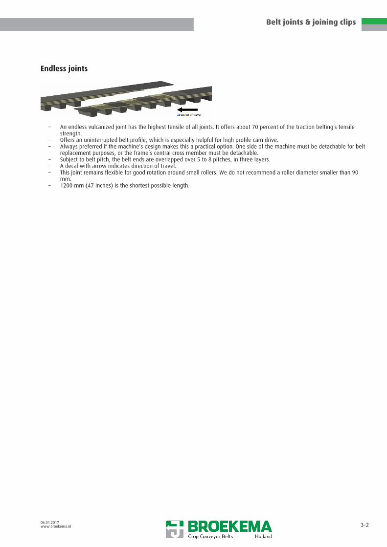
Endless joints
– An endless vulcanized joint has the highest tensile of all joints. It offers about 70 percent of the traction belting´s tensilestrength.
– Offers an uninterrupted belt profile, which is especially helpful for high profile cam drive.– Always preferred if the machine’s design makes this a practical option. One side of the machine must be detachable for belt
replacement purposes, or the frame’s central cross member must be detachable.– Subject to belt pitch, the belt ends are overlapped over 5 to 8 pitches, in three layers.– A decal with arrow indicates direction of travel.– This joint remains flexible for good rotation around small rollers. We do not recommend a roller diameter smaller than 90
mm.– 1200 mm (47 inches) is the shortest possible length.

Belt joints & joining clips
06.01.2017www.broekema.nl 3-3
OVERLAP JOINT
Recommended for heavy duty applications when an endless vulcanized joint is impractical.
– Offers 50 percent of the traction belting's tensile strength.– Offers an uninterrupted belt profile, especially helpful for high profile cam drive.– Retains similar dynamic advantages to an endlessly vulcanized joint.– The belt ends are stepped in either two or three layers.– Minimum end roller diameter 110 mm (4 ¼") for 2 step layered joint type.– Minimum end roller diameter 90 mm (3 1/2") for 3 step layered joint type.– Rivet rods are supplied loose with the conveyor.– The users can assemble or disassemble themselves, but extra care is needed to ensure that securing bolts are well tightened
and rechecked one or twice per season.– Securing options: Compressing the rods and belt ends can either be with M6 nuts and bolts or with M6 socket head screws
using threaded plates. An M6 socket head screw will require a 4 mm hexagon key.

Belt joints & joining clips
06.01.2017www.broekema.nl 3-4
Joining clips, type AB
Design joining rod
Description Opt
ion
al
Belting width[mm]
Pitch[mm]
Hole distance[mm]
Rivet Ø[mm]
Max. rod Ø[mm] Articleno.
4 AB 28-20 40 28 20 5 11M 112000003W 112000004
4 AB 28-24 40 28 24 5 11M 112000005W 112000006
4 AB 32-20 40 32 20 5 11M 112000007W 112000008
4 AB 36-20 40 36 20 5 11M 112000009W 112000010
4 AB 50-20 40 50 20 5 11M 112000011W 112000012
5 AB 28-20 50 28 20 5 11M 112000033W 112000034
5 AB 36-20 50 36 20 5 11M 112000039W 112000040
5 AB 40-20 50 40 20 5 11M 112000041W 112000042
5 AB 42-24 50 42 24 5 11M 112000047W 112000048
5 AB 45-20 50 45 20 5 11M 112000049W 112000050
5 AB 50-20 50 50 20 5 11M 112000051W 112000052
6 AB 28-32 60 28 32 5 11M 112000796W 112000797
6 AB 32-32 60 32 32 5 11M 112000781W 112000782
6 AB 36-20 60 36 20 5 11M 112000109W 112000110
6 AB 36-30 60 36 30 5 11M 112000111W 112000112
6 AB 36-32 60 36 32 5 11M 112000785W 112000786
6 AB 40-30 60 40 30 5 11M 112000115W 112000116
6 AB 42-30 60 42 30 5 11M 112000121W 112000122
6 AB 42-32 60 42 32 5 11M 112000789W 112000790
6 AB 45-32 60 45 32 5 11M 112000798W 112000799

Belt joints & joining clips
06.01.2017www.broekema.nl 3-5
Joining clips, type AF
Design joining rod
Description Opt
ion
al
Belting width[mm]
Pitch[mm]
Hole distance[mm]
Rivet Ø[mm]
Max. rod Ø[mm] Articleno.
5 AF 28-20 50 28 20 5 10 112000053
5 AF 28-24 50 28 24 5,0 10 112000948
5 AF 32-20 50 32 20 5 10 112000054
5 AF 36-20 50 36 20 5 11 112000055
5 AF 40-20 50 40 20 5 11 112000056
5 AF 40-24 50 40 24 5 11 112000946
5 AF 42-20 50 42 20 5 11 112000057
5 AF 42-24 50 42 24 5 10 112000047
5 AF 45-20 50 45 20 5 11 112000058
5 AF 50-20 50 50 20 5 11 112000059
5 AF 56-20 50 56 20 5 11 112000060
6 AF 28-32 60 28 32 5 12 112000838
6 AF 28-30 60 28 30 5 12 112000942
6 AF 32-32 60 32 32 5,0 / 5,5 12 112000131
6 AF 36-30 60 36 30 5,0 12 112000940
6 AF 36-32 60 36 32 5,0 / 5,5 12 112000840
6 AF 40-32 60 40 32 5,0 / 5,5 12 112000841
6 AF 42-32 60 42 32 5,0 / 5,5 12 112000842
6 AF 45-32 60 45 32 5,0 / 5,5 12 112000843
6 AF 50-32 60 50 32 5,0 / 5,5 12 112000844
6 AF 56-32 60 56 32 5,0 / 5,5 12 112000143
6 AAF 28-32 60 28 32 5 11 112000103
6 AAF 32-32 60 32 32 5 11 112000104
* also with 12mm joining rod

Belt joints & joining clips
06.01.2017www.broekema.nl 3-6
Joining clips, type BC
Design joining rod
Description Opt
ion
al
Belting width[mm]
Pitch[mm]
Hole distance[mm]
Rivet Ø[mm]
Max. rod Ø[mm] Articleno.
6 BC 35-20 60 35 20 5 11M 112000145W 112000146
6 BC 35-30 60 35 30 5 11M 112000147W 112000148
6 BC 35-32 60 35 32 5 11M 112000149W 112000151
6 BC 40-30 60 40 30 5 11M 112000153W 112000154
6 BC 40-32 60 40 32 5 11M 112000155W 112000157
6 BC 44-32 60 44 32 5 11M 112000159W 112000160
6 BC 50-32 60 50 32 5 11M 112000161W 112000162

Belt joints & joining clips
06.01.2017www.broekema.nl 3-7
Joining clips, type E
4-hole joining clip plate Design joining rod
Description Opt
ion
al
Belting width[mm]
Pitch[mm]
Hole distance[mm]
Rivet Ø[mm]
Max. rod Ø[mm] Articleno.
6 E 42-32 60 42 32 6 11M 112000176U 112000325W 112000178

Belt joints & joining clips
06.01.2017www.broekema.nl 3-8
Joining clips, type G
Design joining rod
Description Opt
ion
al
Belting width[mm]
Pitch[mm]
Hole distance[mm]
Rivet Ø[mm]
Max. rod Ø[mm] Articleno.
2 G 28-0 20 28 - 5 11 112000965
2 G 32-0 20 32 - 5 11 112000982
2 G 40-0 20 40 - 5 11 112000822
3 G 32-0 30 32 - 5 11M 112000887W 112000888
3 G 35-0 30 35 - 5 11M 112000890W 112000891
3 G 42-0 30 42 - 5 11 112000828
3 G 45-0 30 45 - 5 11M 112000001W 112000002
4 G 28-20 40 28 20 5 11M 112000963W 112000964
4 G 40-20 40 40 20 5 11M 112000899W 112000900
5 G 22-20 50 22 20 5 11M 112000878W 112000879
5 G 28-20 50 28 20 5 11M 112000013W 112000014
5 G 32-20 A * 50 32 20 5 11M 112000015W 112000016
5 G 36-20 50 36 20 5 11M 112000017W 112000017
5 G 36-20 A * 50 36 20 5 11M 112000018W 112000020
5 G 40-20 50 40 20 5 11M 112000021W 112000023
5 G 42-20 50 42 20 5 11M 112000025W 112000027
5 G 42-20 A * 50 42 20 5 11M 112000026W 112000028
5 G 45-20 50 45 20 5 11M 112000031W 112000032
5 G 50-20 50 50 20 5 11M 112000061W 112000062
6 G 22-32 60 22 32 5 11M 112000804W 112000806
6 G 28-32 60 28 32 5 11M 112000063W 112000065
6 G 32-30 60 32 30 5 11M 112000067W 112000068
6 G 32-32 60 32 32 5 11M 112000069W 112000071
6 G 35-30 60 35 30 5 11M 112000073W 112000074
6 G 35-32 60 35 32 5 11M 112000075W 112000076
6 G 36-20 60 36 20 5 11M 112000077W 112000078
6 G 36-30 60 36 30 5 11M 112000079W 112000080
Belt joints & joining clips
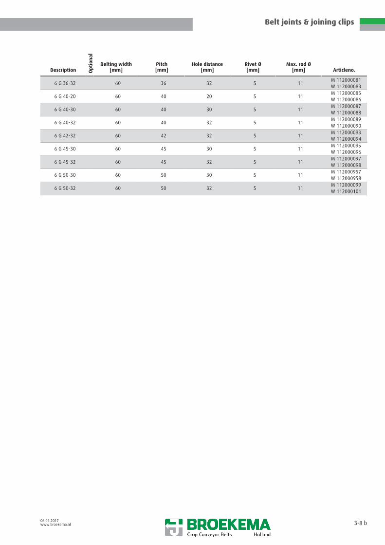
06.01.2017www.broekema.nl 3-8 b
Description Opt
ion
al
Belting width[mm]
Pitch[mm]
Hole distance[mm]
Rivet Ø[mm]
Max. rod Ø[mm] Articleno.
6 G 36-32 60 36 32 5 11M 112000081W 112000083
6 G 40-20 60 40 20 5 11M 112000085W 112000086
6 G 40-30 60 40 30 5 11M 112000087W 112000088
6 G 40-32 60 40 32 5 11M 112000089W 112000090
6 G 42-32 60 42 32 5 11M 112000093W 112000094
6 G 45-30 60 45 30 5 11M 112000095W 112000096
6 G 45-32 60 45 32 5 11M 112000097W 112000098
6 G 50-30 60 50 30 5 11M 112000957W 112000958
6 G 50-32 60 50 32 5 11M 112000099W 112000101

Belt joints & joining clips
06.01.2017www.broekema.nl 3-9
Joining clips, type LW(Low-profile)
joining bolts split pin U-disc
Description Opt
ion
al Hole DistanceLA
[mm]
Max. bolt ØBD
[mm] Articleno.
5 LW 28-24 FZ 24 8 112000795
5 LW 32-24 FZ 24 8
5 LW 33-24 FZ 24 8
5 LW 36-24 FZ 24 8 112000355
5 LW 40-24 FZ 24 8 112000356
5 LW 42-24 FZ 24 8
5 LW 43-24 FZ 24 8
5 LW 44-24 FZ 24 8
5 LW 45-24 FZ 24 8
5 LW 50-24 FZ 24 8
6 LW 36-30/32 FZ 30 / 32 10 112000826
6 LW 40-30/32 FZ 30 / 32 10 112000889
6 LW 42-30/32 FZ 30 / 32 10 112000846
6 LW 50-30/32 FZ 30 / 32 10 112000827

Belt joints & joining clips
06.01.2017www.broekema.nl 3-10
Joining clips, type LW(High-profile)
joining bolts split pin U-disc Tooth block
Description Opt
ion
al Hole DistanceLA
[mm]
Max. bolt ØBD
[mm] Articleno.
5 LW 28-24 HZ 24 8
5 LW 35-24 HZ 24 8
5 LW 40-24 HZ 24 8
5 LW 43-24 HZ 24 8
5 LW 44-24 HZ 24 8
5 LW 50-24 HZ 24 8
6 LW 35-30/32 HZ 30 / 32 10 112000825
6 LW 40-30/32 HZ 30 / 32 10 112000359
6 LW 50-30/32 HZ 30 / 32 10 112000360

Belt joints & joining clips
06.01.2017www.broekema.nl 3-11
Double Pivot, joining'Double Pivot, joining
Design joining rod
Description Opt
ion
al
Belting width[mm]
Pitch[mm]
Max. rod Ø[mm] Articleno.
DP28GAB 60 28 12 112000250
DP32GAB 60 32 12 112000251
DP35GAB 60 35 12 112000254
DP36GAB 60 36 12 112000255
DP40GAB 60 40 12 112000256
DP42GAB 60 42 12 112000257
DP44GAB 60 44 12 112000258
DP45GAB 60 45 12 112000259
DP50GAB 60 50 12 112000260
DP28-50 50 28 12 112000249
DP28-60 60 28 12 112000248
DP35-50 50 35 12 112000253
DP35-60 60 35 12 112000252

Belt joints & joining clips
06.01.2017www.broekema.nl 3-12
Joining clips, type GAB
Design joining rod
Description Opt
ion
al
Belting width[mm]
Pitch[mm]
Hole distance[mm]
Rivet Ø[mm]
Max. rod Ø[mm] Articleno.
5 GAB 32-20 50 32 20 6 12M 112000885W 112000886
6 GAB 28-20 60 28 20 6 12M 112001151W 112001152
6 GAB 28-30 60 28 30 6 12M 112001153W 112001154
6 GAB 28-32 60 28 32 6 12M 112000197W 112000198
6 GAB 32-32 60 32 32 6 12M 112000199W 112000200
6 GAB 36-20 60 36 20 6 12M 112001005W 112001006
6 GAB 36-30 60 36 30 6 12M 112001003W 112001004
6 GAB 36-32 60 36 32 6 12M 112000201W 112000202
6 GAB 40-20 60 40 20 6 12M 112001135W 112001136
6 GAB 40-30 60 40 30 6 12M 112001137W 112001138
6 GAB 40-32 60 40 32 6 12M 112000203W 112000204
6 GAB 42-32 60 42 32 6 12M 112000205W 112000206
6 GAB 44-20 60 44 20 6 12M 112001001W 112001002
6 GAB 44-30 60 44 30 6 12M 112000999W 112001000
6 GAB 45-32 60 45 32 6 12M 112000207W 112000208
6 GAB 50-20 60 50 20 6 12M 112001009W 112001010
6 GAB 50-30 60 50 30 6 12M 112001007W 112001008
6 GAB 50-32 60 50 32 6 12M 112000209W 112000210

Belt joints & joining clips
06.01.2017www.broekema.nl 3-13
Joining clips, type GABL
Design joining rod
Description Opt
ion
al
Belting width[mm]
Pitch[mm]
Hole distance[mm]
Rivet Ø[mm]
Max. rod Ø[mm] Articleno.
6 GABL 36-32 60 36 32 6 12M 112001066U 112001072W 112001067
6 GABL 42-32 60 42 32 6 12M 112001068U 112001073W 112001069

Belt joints & joining clips
06.01.2017www.broekema.nl 3-14
Joining clips, type BS
Design joining rod
Description Opt
ion
al
Belting width[mm]
Pitch[mm]
Hole distance[mm] Bolts
Max. rod Ø[mm] Articleno.
5 BS 30-24 50 30 24 M6 10 112001053
6 BS 28-32 60 28 32 M6 10W 12001255M 12001254
6 BS 32-32 60 32 32 M6 10M 12001257W 12001256
6 BS 35-32 60 35 32 M6 10M 12001258W 12001259
6 BS 40-32 60 40 32 M6 10W 12001261M 12001260
6 BS 42-32 60 42 32 M6 10M 12001262W 12001263
6 BS 45-32 60 45 32 M6 10W 12001265M 12001264
6 BS 50-32 60 50 32 M6 10M 12001266W 12001267
75 BS 35-55 75 35 55 M6 10 112001056

Belt joints & joining clips
06.01.2017www.broekema.nl 3-15
Joining clips, type BSV
Description Opt
ion
al
Belting width[mm]
Pitch[mm]
Hole distance[mm]
Rivet Ø[mm] Articleno.
6 BSV 35-30 60 35 30 5 112001054
6 BSV 40-30 60 40 30 5 112001055

Centre belt construction
06.01.2017www.broekema.nl 4-0
General information 4- 1
NOS 4- 2
Highflex 4- 3
Superflex 4- 4
KS-centre clamp 4- 5
Haulm web clamp 4- 6
Haulm web 3-lips clamp 4- 7
Haulm web 4-lips clamp 4- 8
P-clip 4- 9
WB-type clip 4-10
Centre clip (for a complete rod) 4-11
Centre clip (for half a rod) 4-12
Further centre belt constructions 4-13
centre clamp 4-14
Centre belt construction
06.01.2017www.broekema.nl 4-1
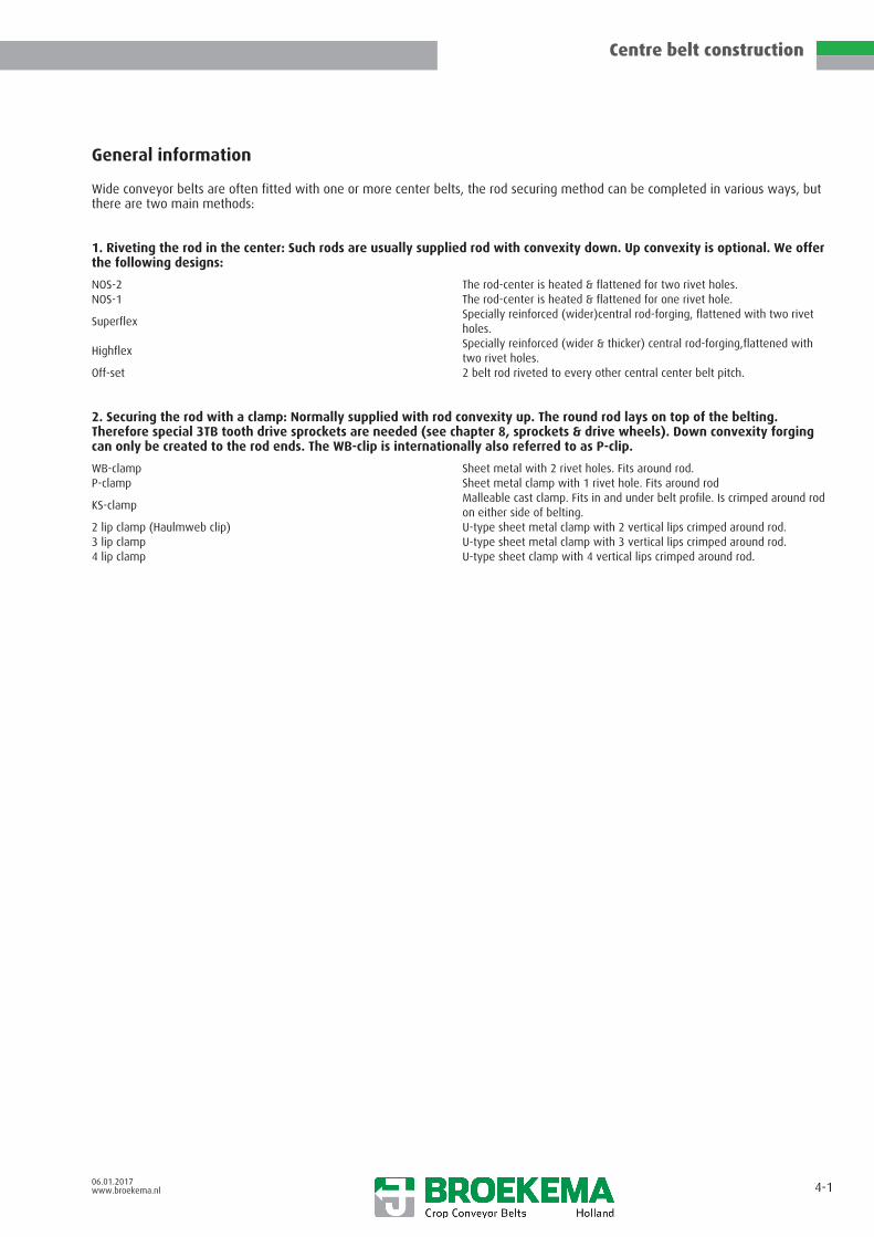
General information
Wide conveyor belts are often fitted with one or more center belts, the rod securing method can be completed in various ways, butthere are two main methods:
1. Riveting the rod in the center: Such rods are usually supplied rod with convexity down. Up convexity is optional. We offerthe following designs:
NOS-2 The rod-center is heated & flattened for two rivet holes.NOS-1 The rod-center is heated & flattened for one rivet hole.
SuperflexSpecially reinforced (wider)central rod-forging, flattened with two rivetholes.
HighflexSpecially reinforced (wider & thicker) central rod-forging,flattened withtwo rivet holes.
Off-set 2 belt rod riveted to every other central center belt pitch.
2. Securing the rod with a clamp: Normally supplied with rod convexity up. The round rod lays on top of the belting.Therefore special 3TB tooth drive sprockets are needed (see chapter 8, sprockets & drive wheels). Down convexity forgingcan only be created to the rod ends. The WB-clip is internationally also referred to as P-clip.
WB-clamp Sheet metal with 2 rivet holes. Fits around rod.P-clamp Sheet metal clamp with 1 rivet hole. Fits around rod
KS-clampMalleable cast clamp. Fits in and under belt profile. Is crimped around rodon either side of belting.
2 lip clamp (Haulmweb clip) U-type sheet metal clamp with 2 vertical lips crimped around rod.3 lip clamp U-type sheet metal clamp with 3 vertical lips crimped around rod.4 lip clamp U-type sheet clamp with 4 vertical lips crimped around rod.

Centre belt construction
06.01.2017www.broekema.nl 4-2
NOSNOS also possible with 1 hole
Description Opt
ion
al
Belting width[mm]
Hole DistanceLA
[mm]
Rod Ød
[mm]Rivet Ø[mm]
NOS-2 40 50 60 75 20-24-30-32 8 5,0
NOS-2 40 50 60 75 20-24-30-32 9 5,0
NOS-2 40 50 60 75 20-24-30-32 10 5,0 / 5,5
NOS-2 40 50 60 75 20-24-30-32 11 5,0 / 5,5 / 6,0
NOS-2 40 50 60 75 20-24-30-32 12 5,0 / 5,5 / 6,0
NOS-2 40 50 60 75 20-24-30-32 13 5,0 / 5,5 / 6,0
NOS-2 40 50 60 75 20-24-30-32 15 5,0 / 5,5 / 6,0
NOS-1 20 30 40 50 60 - 8 5,0
NOS-1 20 30 40 50 60 - 9 5,0
NOS-1 20 30 40 50 60 - 10 5,0 / 5,5
NOS-1 20 30 40 50 60 - 11 5,0 / 5,5 / 6,0
NOS-1 20 30 40 50 60 - 12 5,0 / 5,5 / 6,0
NOS-1 20 30 40 50 60 - 13 5,0 / 5,5 / 6,0
NOS-1 20 30 40 50 60 - 15 5,0 / 5,5 / 6,0

Centre belt construction
06.01.2017www.broekema.nl 4-3
Highflex
Description Opt
ion
al
Belting width[mm]
Hole DistanceLA
[mm]
Rod Ød
[mm]Rivet Ø[mm]
Highflex 40 50 60 75 20-24-30-32 9 5
Highflex 40 50 60 75 20-24-30-32 10 5,0 / 5,5
Highflex 40 50 60 75 20-24-30-32 11 5,0 / 5,5 / 6,0
Highflex 40 50 60 75 20-24-30-32 12 5,0 / 5,5 / 6,0
Highflex 40 50 60 75 20-24-30-32 13 5,0 / 5,5 / 6,0
Highflex 40 50 60 75 20-24-30-32 15 5,0 / 5,5 / 6,0

Centre belt construction
06.01.2017www.broekema.nl 4-4
Superflex
Description Opt
ion
al
Belting width[mm]
Hole DistanceLA
[mm]
Rod Ød
[mm]Rivet Ø[mm]
Superflex 40 50 60 75 20-24-30-32 9 5
Superflex 40 50 60 75 20-24-30-32 10 5,0 / 5,5
Superflex 40 50 60 75 20-24-30-32 11 5,0 / 5,5 / 6,0
Superflex 40 50 60 75 20-24-30-32 12 5,0 / 5,5 / 6,0
Superflex 40 50 60 75 20-24-30-32 13 5,0 / 5,5 / 6,0
Superflex 40 50 60 75 20-24-30-32 15 5,0 / 5,5 / 6,0

Centre belt construction
06.01.2017www.broekema.nl 4-5
KS-centre clamp
Description Opt
ion
al Belting widthRb
[mm]
Width of the bracketL
[mm]
Rod Ød
[mm] Articleno.
KS 10 60 90 10 113000010
KS 11 60 90 11 113000011
KS 12 60 90 12 113000012

Centre belt construction
06.01.2017www.broekema.nl 4-6
Haulm web clamp
Description Opt
ion
al Belting widthRb
[mm]
Hole DistanceLA
[mm]
Rod Ød
[mm]
Rivet ØND
[mm] Articleno.
Haulm web clamp 30 24 8-10 5 113000039
Centre belt construction
06.01.2017www.broekema.nl 4-7
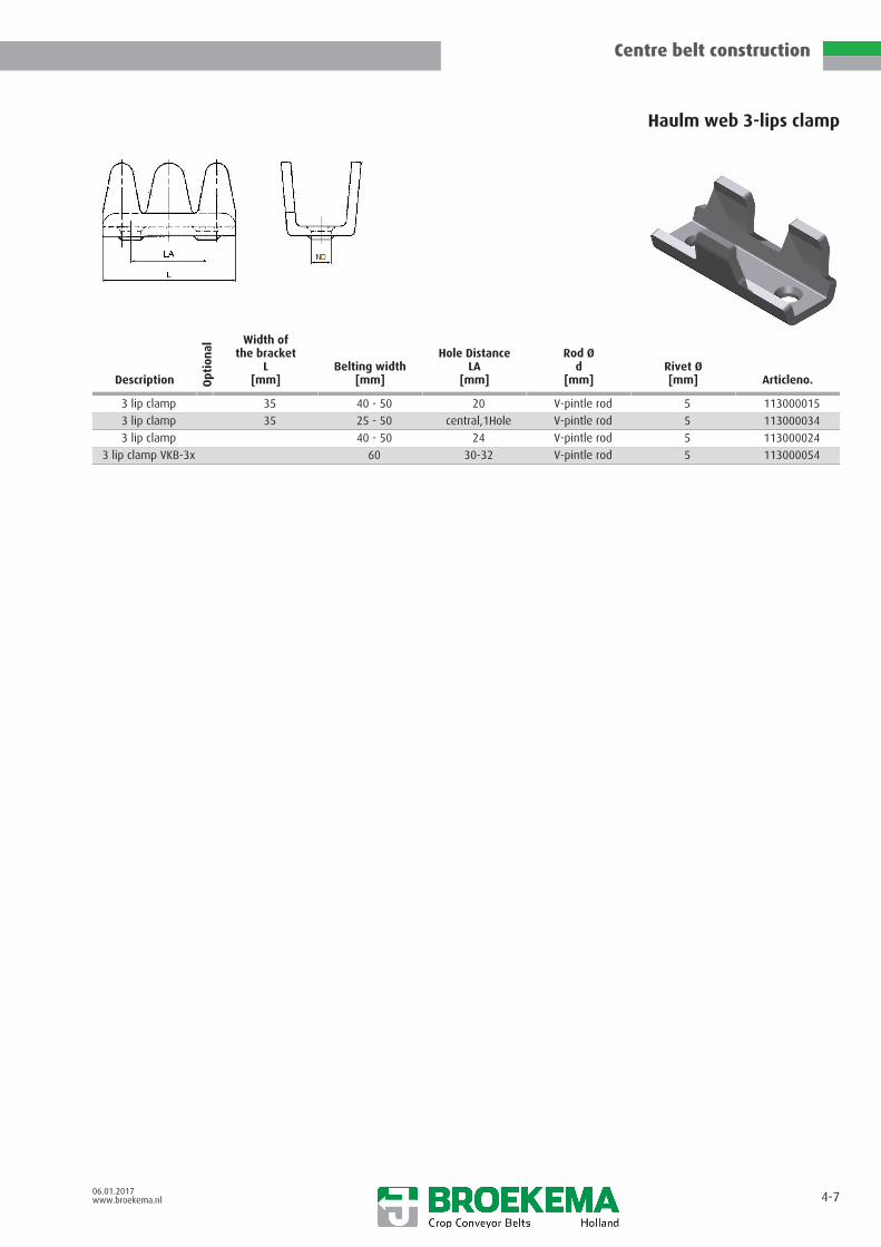
Haulm web 3-lips clamp
Description Opt
ion
al
Width ofthe bracket
L[mm]
Belting width[mm]
Hole DistanceLA
[mm]
Rod Ød
[mm]Rivet Ø[mm] Articleno.
3 lip clamp 35 40 - 50 20 V-pintle rod 5 113000015
3 lip clamp 35 25 - 50 central,1Hole V-pintle rod 5 113000034
3 lip clamp 40 - 50 24 V-pintle rod 5 113000024
3 lip clamp VKB-3x 60 30-32 V-pintle rod 5 113000054

Centre belt construction
06.01.2017www.broekema.nl 4-8
Haulm web 4-lips clamp
Description Opt
ion
al Belting widthRb
[mm]
Hole DistanceLA
[mm]
Rod Ød
[mm]
Rivet ØND
[mm] Articleno.
4-lips clamp 50 – 60 20 12 x 6 (flat) 5 113000013
4-lips clamp 50 – 60 32 12 x 6 (flat) 5 113000014

Centre belt construction
06.01.2017www.broekema.nl 4-9
P-clip
Description Opt
ion
al
Belting width[mm]
Rod Ød
[mm]Rivet Ø[mm] Articleno.
P-clip 20 8 5 113000002
P-clip 20 10 5 113000005
P-clip 20 11 5 113000008
P-clip 30 11 5 113000061
P-clip 20 12 5 113000023

Centre belt construction
06.01.2017www.broekema.nl 4-10
WB-type clip
Description Opt
ion
al
Belting width[mm]
Hole DistanceLA
[mm]
Rod Ød
[mm]Rivet Ø[mm] Articleno.
WB-Type clip 50 20 8 5 113000001
WB-Type clip 60 – 75 32 10 5 113000004
WB-Type clip 60 – 75 30 11 5 113000021
WB-Type clip 60 - 75 30 11 6 113000006
WB-Type clip 60 – 75 32 11 6 113000007
WB-Type clip 60 – 75 32 12 6 113000009

Centre belt construction
06.01.2017www.broekema.nl 4-11
Centre clip (for a complete rod)standard: not hardened
Description Opt
ion
al Belting widthRb
[mm]
Hole DistanceLA
[mm]
Rod Ød
[mm]
Rivet ØND
[mm] Articleno.
Centre clip/21 50 24 10 6 113000042
Centre clip/23 * 50 24 11 6 -
Centre clip/24 * 50 24 12 6 -
Centre clip/25 * 50 24 12.5 6 -
Centre clip/35 * 60 24 10 5.5 113000047
Centre clip/30 * 60 24 10 6 -
Centre clip/32 * 60 24 11 6 113000046
Centre clip/33 * 60 24 12 6 -
Centre clip/34 * 60 24 12.5 6 -
Centre clip/01 60 30 10 6 113000030
Centre clip/03 60 30 11 6 113000031
Centre clip/04 60 30 12 6 113000032
Centre clip/05 60 30 12.5 6 113000033
Centre clip/06 * 60 30 14 6 -
Centre clip/11 * 60 32 10 6 -
Centre clip/13 * 60 32 11 6 -
Centre clip/14 * 60 32 12 6 -
Centre clip/36 * 60 32 12.5 5.5 -
Centre clip/15 * 60 32 12.5 6 113000041
Centre clip/40 75 55 11 6 113000035
Centre clip/41 * 75 55 12 6 -

Centre belt construction
06.01.2017www.broekema.nl 4-12
Centre clip (for half a rod)standard: not hardened
Description Opt
ion
al Belting widthRb
[mm]
Hole DistanceLA
[mm]
Rod Ød
[mm]
Rivet ØND
[mm] Articleno.
Centre clip/21 50 24 10 6 113000045
Centre clip/23 * 50 24 11 6 -
Centre clip/24 * 50 24 12 6 -
Centre clip/25 * 50 24 12.5 6 -
Centre clip/35 * 60 24 10 5.5 113000056
Centre clip/30 * 60 24 10 6
Centre clip/32 * 60 24 11 6 -
Centre clip/33 * 60 24 12 6 -
Centre clip/34 * 60 24 12.5 6 -
Centre clip/01 60 30 10 6 113000029
Centre clip/03 60 30 11 6 113000036
Centre clip/04 60 30 12 6 -
Centre clip/05 60 30 12.5 6 113000037
Centre clip/11 * 60 32 10 6 113000051
Centre clip/13 * 60 32 11 6 113000049
Centre clip/14 * 60 32 12 6 -
Centre clip/36 * 60 32 12.5 5.5 -
Centre clip/15 * 60 32 12.5 6 113000048
Centre clip/40 75 55 11 6 113000038

Centre belt construction
06.01.2017www.broekema.nl 4-13
Further centre belt constructions
overlapped riveted Off-set riveted Off-set riveted 4-belts

Centre belt construction
06.01.2017www.broekema.nl 4-14
centre clamp
Description Opt
ion
al
Width ofthe bracket
L[mm]
Belting width[mm]
Hole DistanceLA
[mm]
Rod Ød
[mm]
Rivet ØND
[mm] Articleno.
HKB / 3X 48 50 - 75 central,3X 5 113000066

Rivet rods
06.01.2017www.broekema.nl 5-0
General information 5- 1
Hole distance 5- 2
Rod ends 5- 3
Cranked rods 5- 4
Rod material 5- 5
Twin-rods 5- 6
Welded twin rod 5- 7
Belt assemblies with square meshdesign
5- 8
Element-droplink 5- 9
Element droplink 5-10

Rivet rods
06.01.2017www.broekema.nl 5-1
General information
The manufacturing process of a rivet rod is comprised of various operations:
– The round steel is cut to length in relationship to the conveyor’s width specification.– If the rod’s centre is to be secured to one or more central traction beltings by rivets, those areas are heated, forged/flattened
and punched. For Super-Flex ® and High-Flex centres the heated rod is subjected to compression which forms a hot bulbousmass at the belting attachment areas.
– These hot areas are formed into the shape of our proprietary Super-Flex ® and High-Flex centres which give the rod anincreased cross-section in its weakest spot, the attachment area/rivet holes of the centre beltings.
– No central area heat treatment takes place if the rod is to be secured to the belting by means of central retainingclamps/clips.
– The rod ends are then heated prior to the forge/flattening process, which also forms the rod’s convexity and, if applicable,the rod is cranked, then punched with optionally spaced rivet holes.
– If required with heavy duty applications, the rod can be hardened and stress relieved to maintain consistent materialproperties over its full length.
The centre to centre distance between a rod’s outer rivet holes is called the ‘Stickmark” or ‘Stokmaat’ which for Broekema Holland &Broekema U.S.A. determines a steel rod length for production purposes to arrive at a total beltwidth.
Artemis Germany requires a rod’s overall length measurement (rod width) to determine the conveyor´s overall width. It is veryimportant to refer to either the stickmark or the rod width when ordering replacement rods.
Steel qualities:
– Spring steel: This steel quality is cold drawn and available in classes B, C or S. It offers a very high hardness & wearresistance. Subject to rod pitch & rod stress loading, these steels are suitable in many normal to heavy applications.
– Hot rolled steel 55Si7 & Boron alloyed steel are suited to post hardening and a stress relief process. They are good forextreme load applications. The Boron-alloyed steel is well suited to applications which involves welding-on metal pins, steelrisers/flights, etc.. Whilst heat treating & forge flattening reduces the base material’s strength, the rod’s strength will beconsistent over its total length, if the rod is hardened & stress relieved.
– Stainless steel rods are available in 305 quality for belt-assemblies which run into salt- or underwater conditions in order notto effect rusting.
Weight saving is possible by using aluminum or fiberglass rods. Their ends are enclosed in special end pieces which allow riveting tothe belting.
Twin rods divides the belt pitch over 2 rods, offering narrow rod clearances which can be further reduced by means of rod coverings.To avoid Twin-rod wear, special Twin-rod conveyors are usually friction or cam driven.

Rivet rods
06.01.2017www.broekema.nl 5-2
Hole distancepossible design
Description Opt
ion
al Belting widthRb
[mm] Standard
Hole DistanceLa
[mm]
Hole DistanceLA
[mm]
Rod Ød
[mm]
Distancea
[mm]
WidthB
[mm]
Rod 50 X 24 11,5
Rod 60 X 30 13,5
Rod 60 X 32 12,5
Rod 75 X 30 21
Rod 75 X 32 20
Rod X 8 13
Rod X 9 15
Rod X 10 17
Rod X 11 19
Rod X 12 17
Rod X 12,5 18
Rod X 7 10
Rod X 8 12
Rod X 9 14
Rod X 10 15
Rod X 11 16
Rod X 12 17
Rod X 13 19
Rod X 15 22
Rod 40 X 20 belt width- 23
Rod 45 20 belt width- 28
Rod 50 X 20 belt width- 33
Rod 50 24 belt width- 29
Rod 60 30 belt width- 35
Rod 60 X 32 belt width- 31
Rod 75 30 belt width- 40
Rod 75 X 32 belt width- 46
Rod 75 38 belt width- 40

Rivet rods
06.01.2017www.broekema.nl 5-3
Rod endspossible design
Description Opt
ion
al
Picture Convexity
Convexity Down Convexity down
Convexity Up Convexity up
Central Convexity * Central convexity

Rivet rods
06.01.2017www.broekema.nl 5-4
Cranked rodspossible design
Description Opt
ion
al
PictureMax. cranked
KBroekema
min. XArtemismin. X
Broekema standardK
Ro -70 0 intervals from 5 mm
Ru + 70 0 intervals from 5 mm

Rivet rods
06.01.2017www.broekema.nl 5-5
Rod material(technical details)
Description Opt
ion
al
Raw material Nr.
Rod Ød
[mm]Possible designnot hardened
Possible designhardened Articleno.
Steel 1.7223 5 X 114000033
Steel 1.7223 6 X 114000034
Steel 1.7223 7 X 114000035
Steel 1.7223 8 X 114000036
Steel 1.7223 9 X 114000037
Steel 1.7223 10 X
Steel 1.7223 8 X
Steel 1.7223 9 X
Steel 1.7223 10 X 114000039
Steel 1.7223 11 X 114000040
Steel 1.7223 12 X 114000041
Steel * 1.7223 13,5 X
Steel 10 X
Steel 11 X
Steel 12 X
Steel 12,5 X
Steel 1.0904 10 X X 114000028
Steel 1.0904 11 X X 114000029
Steel 1.0904 12 X X 114000030
Steel 1.0904 13 X X 114000031
Steel 1.0904 15 X X 114000032
Steel SB27M12CB 10 X 114000001
Steel SB27M12CB 11 X 114000002
Steel SB27M12CB 12 X 114000003
Steel SB27M12CB 13 X 114000004
Stainless Steel 304 6 114000020
Stainless Steel * 304 7 114000021
Stainless Steel * 304 8 114000022
Stainless Steel * 304 9 114000023
Stainless Steel * 304 10 114000024
Stainless Steel * 304 11 114000026
Stainless Steel * 304 12 114000027
Stainless Steel * 304 13 G01RVS13
Fibreglass 6 116000001
Fibreglass 8 116000002
Fibreglass 10 116000003

Rivet rods
06.01.2017www.broekema.nl 5-6
Twin-rods
Description Opt
ion
al
Pitch[mm] Rod pitch
Rod Ød
[mm]
Gap betweenrods
[mm] Steel Stainless Steel GFK
Twin-rods 28 14 5 9 X X
Twin-rods 28 14 6 8 X X
Twin-rods 32 16 5 11 X
Twin-rods 32 16 6 10 X
Twin-rods 32 16 7 9 X
Twin-rods 32 16 8 8 X X X
Twin-rods 35 17.5 5 12.5 X
Twin-rods 35 17.5 6 11.5 X
Twin-rods 35 17.5 7 10.5 X X
Twin-rods 35 17.5 8 9.5 X X X
Twin-rods 35 17.5 9 8.5 X
Twin-rods 36 18 5 13 X
Twin-rods 36 18 6 12 X X
Twin-rods 36 18 7 11 X X
Twin-rods 36 18 8 10 X X X
Twin-rods 36 18 10 8 X X X
Twin-rods 40 20 5 15 X
Twin-rods 40 20 6 14 X X
Twin-rods 40 20 7 13 X X
Twin-rods 40 20 8 12 X X
Twin-rods 40 20 9 11 X
Twin-rods 40 20 10 10 X X X
Twin-rods 42 21 5 16 X X
Twin-rods 42 21 6 15 X
Twin-rods 42 21 7 14 X X
Twin-rods 42 21 8 13 X X
Twin-rods 44 22 5 17 X
Twin-rods 44 22 6 16 X X
Twin-rods 44 22 7 15 X
Twin-rods 44 22 8 14 X X X
Twin-rods 45 22.5 5 17.5 X
Twin-rods 45 22.5 6 16.5 X X
Twin-rods 45 22.5 7 15.5 X
Twin-rods 45 22.5 8 14.5 X X X
Twin-rods 50 25 5 20 X
Twin-rods 50 25 6 19 X
Twin-rods 50 25 7 18 X X
Twin-rods 50 25 8 17 X X
Twin-rods 50 25 9 16 X X
Twin-rods 56 28 5 23 X
Twin-rods 56 28 7 21 X

Rivet rods
06.01.2017www.broekema.nl 5-7
Welded twin rod
Description Opt
ion
al Rod Ød
[mm] Boron Stainless Steel
Welded twin rod 8 X X
Welded twin rod 9 X
Welded twin rod 10 X X
Welded twin rod 11 X X
Welded twin rod 12 X X
This rod type is available in many versions. Ask our technical department for the possibilities.

Rivet rods
06.01.2017www.broekema.nl 5-8
Belt assemblies with square mesh design
standardoptionaloptional

Rivet rods
06.01.2017www.broekema.nl 5-9
Droplink
possible design
Design of belt with two traction beltsstandard
optional
Design of belt with three traction beltsstandard
optional

Rivet rods
06.01.2017www.broekema.nl 5-10
Element droplink
Description Opt
ion
al
Rawmaterial Nr.
Max. rod ØSdmax[mm]
LengthL
[mm]
Min. PitchTmin[mm]
Max. pitchTmax[mm]
WidthB
[mm] Articleno.
droplink * rubber 13 195 40 50 160 -
droplink PU 13 195 40 50 160 -
droplink PU 13 200 40 40 160 115008413

Vulcanised rods
06.01.2017www.broekema.nl 6-0
General information 6- 1
Pintle rod, 1 row 6- 2
Pintle rods, 1-row 6- 3
Pintle rods, 1-row_finger outside 6- 4
Pintle rod, 2 row 6- 5
Pintle rod, 2 row 6- 6
Pintle rod, 4 row 6- 7
Pintle plate rods 6- 8
V-pintle rod 6- 9
Pintle rod, V-profile 6-10
Pintle rod, V-profilel 2 row 6-11
Rivet rods for flights 6-12
Rubber covered rod (bonded) 6-13
C-Flex 6-14
PEG-link 6-15
PES Elavatorweb 6-16

Vulcanised rods
06.01.2017www.broekema.nl 6-1
General information
Vulcanized rods are used in many harvesting machines. We can offer these rods for different applications, such as:
– 1-Row pintle rods to be used as flight– Carefully clean and sieve with V-profile pintle rods– Transporting and cleaning with H-pintle rods and pintle plates– Wear and noise protection for flights and droplinks– C-Flex for bruise protection and to be used as flight– Rods for wide mesh haulm webs
We have extensive possibilities to offer vulcanized rods for many widths and designs.
We can supply V-profile pintle rods for webs with one or more center belts, with the possible use of 3-lip clamps to secure the rodson to the belting.
Pintle rods on flat steel (30x4) can be cut off at each required width.
Rubber compounds with different hardnesses, tailored to your application are available, thus harvesting your fragile crop carefully.High wear resistance will guarantee a long durability.
Our products are characterized by a particularly high bond strength between rubber and metal, where our laboratory ensures a highlevel quality.
We develop new mixtures and have access to our own mixing installation for new or further development of your products.

Vulcanised rods
06.01.2017www.broekema.nl 6-2
Pintle rod, 1 row
Description Opt
ion
al
Rod Steel qualityRod width
[mm]Pintleheight
[mm] Pintle distance
Belt widthBb
[mm]
Pintle rod ona flat strip
30x4 (flat) C 60 30 32 20 < 2000
Pintle rod ona round rod
10 Class C 30 32 20> 456 – 1496
<Interval = 20 mm
Vulcanised rods
06.01.2017www.broekema.nl 6-3
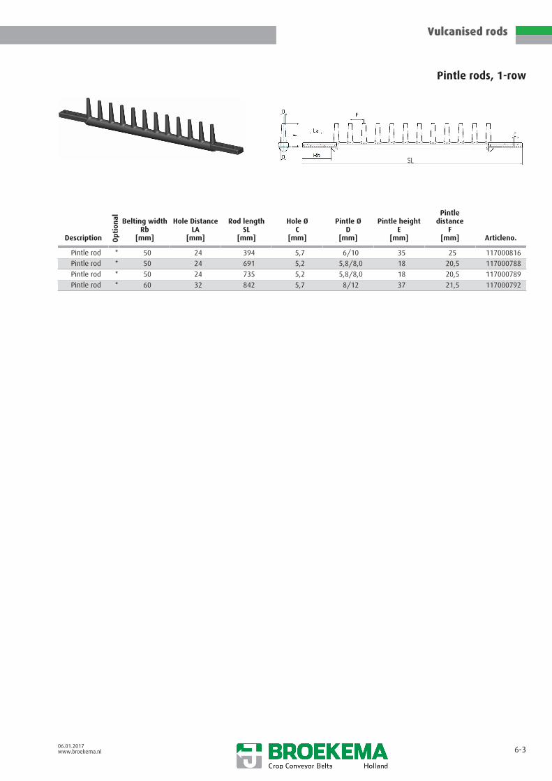
Pintle rods, 1-row
Description Opt
ion
al Belting widthRb
[mm]
Hole DistanceLA
[mm]
Rod lengthSL
[mm]
Hole ØC
[mm]
Pintle ØD
[mm]
Pintle heightE
[mm]
Pintledistance
F[mm] Articleno.
Pintle rod * 50 24 394 5,7 6/10 35 25 117000816
Pintle rod * 50 24 691 5,2 5,8/8,0 18 20,5 117000788
Pintle rod * 50 24 735 5,2 5,8/8,0 18 20,5 117000789
Pintle rod * 60 32 842 5,7 8/12 37 21,5 117000792

Vulcanised rods
06.01.2017www.broekema.nl 6-4
Pintle rods, 1-row_finger outside
Description Opt
ion
al Belting widthRb
[mm]
Hole DistanceLA
[mm]
Rod lengthSL
[mm]
Hole ØC
[mm]
Pintle ØD
[mm]
Pintle heightE
[mm]
Pintledistance
F[mm] Articleno.
Pintle rod 60 20 298 5,2 6/10 35 25 117000125
Pintle rod 60 20 348 5,2 6/10 35 25 117000119
Pintle rod 50 24 594 5,2 7 35 25 117000139
Pintle rod 60 20 673 5,2 6/10 35 25 117000118
Pintle rod 60 20 673 5,2 6/10 35 25 117000118
Pintle rod 60 20 698 5,2 6/10 35 25 117000124
Pintle rod 50 24 748 5,2 5/12 31 21,5 117000111
Pintle rod 50 24 748 5,7 5/12 31 21,5 117000779
Pintle rod 50 24 996 5,7 5/9 34 25 117000759

Vulcanised rods
06.01.2017www.broekema.nl 6-5
Pintle rod, 2 row
Description Opt
ion
al Belting widthRb
[mm]
Hole DistanceLa
[mm]
Rod lengthSL
[mm]
Hole ØC
[mm]
Pintle ØD
[mm]
Pintle heightE
[mm]
Pintledistance
F[mm] Articleno.
Pintle rod 50 24 440 6,2 7 30 20 117000012
Pintle rod 50 24 480 5,7 6 30 20 117000784
Pintle rod 60 30 480 6,2 6 30 20 117000013
Pintle rod 50 24 481 5,7 8,5 32 20 117000014
Pintle rod 60 30 604 5,7 6 30 20 117000015
Pintle rod * 60 32 650 5,7 6 30 20 117000016
Pintle rod 60 30 680 6,2 6 30 20 117000017
Pintle rod * 60 32 848 6,2 6 30 20 117000793
Pintle rod 60 30 895 5,2 7 30 20
Pintle rod 60 30 795 5,2 7 30 20
Pintle rod 60 30 725 5,2 6 30 20

Vulcanised rods
09.01.2017www.broekema.nl 6-6
Pintle rod, 2 row
Description Opt
ion
al Belting widthRb
[mm]
Hole DistanceLa
[mm]
Rod lengthSL
[mm]
Hole ØC
[mm]
Pintle ØD
[mm]
Pintle heightE
[mm]
Pintledistance
F[mm] Articleno.
Pintle rod 50 32 650-1650 6,2 7 30 20 117000012

Vulcanised rods
06.01.2017www.broekema.nl 6-7
Pintle rod, 4 row
Description Opt
ion
al Belting widthRb
[mm]
Hole DistanceLa
[mm]
Rod lengthSL
[mm]
Hole ØC
[mm]
Pintle ØD
[mm]
Pintle heightE
[mm]
Pintledistance
F[mm] Articleno.
Pintle rod * 60 35 648 6,5 4 45 11,7 117000801

Vulcanised rods
06.01.2017www.broekema.nl 6-8
Pintle plate rods
Description Opt
ion
al
Fill-ring[mm]
Hole DistanceLA
[mm]
Hole ØC
[mm]
Pintle ØD
[mm]
Pintle heightE
[mm] Articleno.
Pintle plate rods 509 24 5,7 6 32 117000044
Pintle plate rods * 509 24 5,7 4,5 52 Keine Form
Pintle plate rods 646,5 24 5,7 6 35 117000045
Pintle plate rods 646,5 24 5,7 4,5 38 117000047

Vulcanised rods
06.01.2017www.broekema.nl 6-9
V-pintle rod
Description Opt
ion
al Hole DistanceLa
[mm]
Hole DistanceLA
[mm]
Belt widthBb
[mm]
Rod 32 219 - 2269 255 - 2305
Rod 30 219 - 2269 255 - 2305
Rubber finger *

Vulcanised rods
06.01.2017www.broekema.nl 6-10
Pintle rod, V-profile
Description Opt
ion
al Belting widthRb
[mm]
Hole DistanceLa
[mm]
Rod lengthSL
[mm]
Hole ØC
[mm]
Pintle ØD
[mm]
Pintle heightE
[mm]
Pintledistance
F[mm] Articleno.
Pintle rod * 60 32 796 5,7 cone 33,5 28 117000037
Pintle rod * 60 32 842 5,7 cone 33,5 28 117000804
Pintle rod * 60 32 879 5,7 cone 33,5 28 117000020
Pintle rod * 60 32 879 5,7 cone 33,5 28 117000021
Pintle rod * 60 32 996 5,7 cone 33,5 28 117000039
Pintle rod * 60 32 996 5,7 cone 33,5 28 -
Pintle rod * 60 30 1196 5,7 cone 33,5 28 117000021
Pintle rod * 60 30 1196 5,7 cone 33,5 28 117000776
Pintle rod * 60 32 1246 5,7 cone 33,5 28 117000022
Pintle rod * 60 32 1246 5,7 cone 33,5 28 117000023
Pintle rod * 60 32 1451 5,7 cone 33,5 28 117000025
Pintle rod * 60 32 1451 5,7 cone 33,5 28 117000024
Pintle rod * 60 32 1621 5,7 cone 33,5 28 117000026
Pintle rod * 60 32 1621 5,7 cone 33,5 28 117000027
Pintle rod * 60 32 1646 5,7 cone 33,5 28 117000029
Pintle rod * 60 32 1646 5,7 cone 33,5 28 117000021
Pintle rod * 60 32 1676 5,7 cone 33,5 28 117000030
Pintle rod * 60 32 1676 5,7 cone 33,5 28 117000031
Pintle rod * 60 32 1696 5,7 cone 33,5 28 117000033
Pintle rod * 60 32 1696 5,7 cone 33,5 28 117000032

Vulcanised rods
06.01.2017www.broekema.nl 6-11
Pintle rod, V-profilel 2 row
Description Opt
ion
al Belting widthRb
[mm]
Hole DistanceLa
[mm]
Rod lengthSL
[mm]
Hole ØC
[mm]
Pintle ØD
[mm]
Pintle heightE
[mm]
Pintledistance
F[mm] Articleno.
Pintle rod * 60 30 610 5,7 5,5 26 17 117000799
Pintle rod * 60 32 696 5,7 6 28 17 117000606
Pintle rod 60 30 605 5,2 7-9cone 30 23
Pintle rod 60 32 696 5,7 7-9cone 30 25
Pintle rod 60 30 725 5,2 7-9cone 30 23
Pintle rod 60 30 855 5,2 7-9cone 30 20
Pintle rod 60 30 895 5,2 7-9cone 30 23
Pintle rod 60 30 996 5,2 7-9cone 30 23
Vulcanised rods
06.01.2017www.broekema.nl 6-12
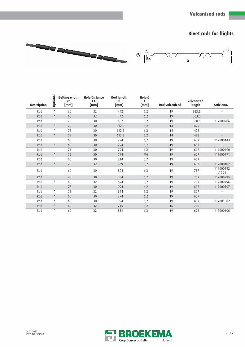
Rivet rods for flights
Description Opt
ion
al Belting widthRb
[mm]
Hole DistanceLA
[mm]
Rod lengthSL
[mm]
Hole ØC
[mm] Rod vulcanizedVulcanized
length Articleno.
Rod * 60 32 442 6,2 19 363,5 -
Rod * 60 32 442 6,2 19 363,5 -
Rod 75 30 482 6,2 19 388.5 117000786
Rod * 75 30 612,5 6,2 14 425 -
Rod * 75 30 612,5 6,2 14 425 -
Rod * 75 30 612,5 6,2 14 425 -
Rod 60 30 794 6,2 19 637 117000143
Rod * 60 30 794 5,7 19 637 -
Rod 75 30 794 6,2 19 607 117000790
Rod * 75 30 794 M6 19 607 117000791
Rod 60 30 814 5,7 19 657 -
Rod * 75 32 839 6,2 19 652 117000107
Rod 60 30 894 6,2 19 737117000142
/ 794Rod 75 30 894 6,2 19 707 117000795
Rod * 60 32 894 6,2 19 737 117000796
Rod 75 30 994 6,2 19 807 117000797
Rod * 75 32 994 6,2 19 807 -
Rod * 60 30 794 6,2 19 637 -
Rod * 60 30 994 6,2 19 807 117001002
Rod * 60 32 745 5,2 16 750 -
Rod * 60 32 831 6,2 19 672 117000106

Vulcanised rods
06.01.2017www.broekema.nl 6-13
Rubber covered rod (bonded)
Description Opt
ion
al Belting widthRb
[mm]
Hole DistanceLA
[mm]
Rod lengthSL
[mm]
Hole ØC
[mm] Rod vulcanizedVulcanized
length Articleno.
Rod 60 30 637 5,7 14 510 117000800
Rod 60 30 586 5,7 14 430 117000798
Rod 60 30 687 5,7 14 560 117000813

Vulcanised rods
06.01.2017www.broekema.nl 6-14
C-Flex
Description Opt
ion
al Belt widthBb
[mm]
Rod Ød
[mm]Design straight
with wingsDesign cranked
with wings Articleno.
620 [24,5 inches] 11 X
760 [30 inches] 11 X X
785 [31 inches] 11 X X
835 [33 inches] 11 X X
885 [35 inches] 11 X X
900 [35,5 inches] 11 X
910 [36 inches] 11 X X
985 [39 inches] 11 X
1015 [40 inches] 11 X X
1065 [42 inches] 11 X X
1520 [60 inches] 11 X
1560 [61,5 inches] 11 X
1570 [62 inches] 11 X
1585 [62,5 inches] 11 X
1610 [63,5 inches] 11 X X
1650 [65 inches] 11 X
1725 [68 inches] 11 X X
1750 [69 inches] 11 X X
1775 [70 inches] 11 X
Vulcanised rods
06.01.2017www.broekema.nl 6-15
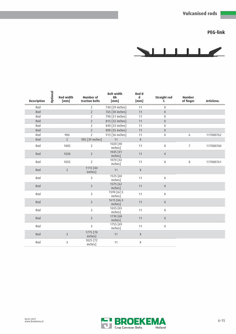
PEG-link
Description Opt
ion
al
Rod width[mm]
Number oftraction belts
Belt widthBb
[mm]
Rod Ød
[mm]Straight rod
SNumberof finger Articleno.
Rod 2 740 [29 inches] 11 X
Rod 2 765 [30 inches] 11 X
Rod 2 790 [31 inches] 11 X
Rod 2 815 [32 inches] 11 X
Rod 2 840 [33 inches] 11 X
Rod 2 890 [35 inches] 11 X
Rod 900 2 915 [36 inches] 11 X 6 117000762
Rod 2 985 [39 inches] 11 X
Rod 1005 21020 [40inches]
11 X 7 117000760
Rod 1030 21045 [41inches]
11 X
Rod 1055 21070 [42inches]
11 X 8 117000761
Rod 21115 [44inches]
11 X
Rod 31525 [60inches]
11 X
Rod 31575 [62inches]
11 X
Rod 31590 [62,5
inches]11 X
Rod 31615 [66,5
inches]11 X
Rod 31655 [65inches]
11 X
Rod 31730 [68inches]
11 X
Rod 31755 [69inches]
11 X
Rod 31775 [70inches]
11 X
Rod 31825 [72inches]
11 X

Vulcanised rods
06.01.2017www.broekema.nl 6-16
PES Elavatorweb
Description Opt
ion
al Belting widthRb
[mm]
Hole DistanceLA
[mm]
Rod lengthSL
[mm]
Hole ØC
[mm]
Pintle ØD
[mm]
Pintle heightE
[mm]
Pintledistance
F[mm] Articleno.
* 60 32 517 5,7 - - 50 117000084
* 60 32 605 5,7 - - 50 -
* 60 32 717 5,7 - 120 100 -
* 60 32 817 5,7 - 120 100 -
* 60 32 917 5,7 - 120 100 117000095
* 60 32 992 5,7 - - 50 117000089
* 60 32 992 5,7 - - 100 117000091
* 60 32 1034 5,7 - - 50 F233C
* 60 32 1062 5,7 - - 50 -
* 60 32 1092 5,7 - - 100 117000094
* 60 32 589 5,7 - - 50 117000085
* 60 32 689 5,7 - - 100 117000096

Rod coverings
06.01.2017www.broekema.nl 7-0
General information 7- 1
PVC covering - Split 7- 2
PVC covering - Pillow-Cushion 7- 3
PVC covering - Star 7- 4
Soft PVC 7- 5
PVC covering - Full 7- 6
Rubber covering - Star 7- 7
Rubber covering - Full 7- 8
Rubber profile 7- 9
C-Flex 7-10

Rod coverings
06.01.2017www.broekema.nl 7-1
General information
Rivet rods & connector rods may be covered to reduce crop damage, or to increase rod diameter and so reduce rod gap clearance.Options are listed below in order of increased crop protection:
–Hard black LDPE tubing: Offers no crop cushioning protection, mainly used to increase rod diameter/reducing rod clearance.
– “Split type” LDPE: This is a lengthwise cut tubing, so may be fitted or removed later. Its friction fit permits a second layer oflarger diameter. May be ordered cut to length or in coils.
–Rubber ‘cushion’ tubing: Fitted at time of manufacture. Undersized friction fit with a bonding agent if sprocket runclearways are needed. Without such clearways covering may be at, or greater than rod diameter. The latter increasescushioning effect. For covering joining rods, order cut to length or in coils.
–Plastic internal star profile: Fitted at time of manufacture. A soft plastic tube with goods cushioning effect, which improveswhen internal diameter need not be a friction fit on rods. For covering joining rods, order cut to length or coils.
–Rubber internal star profile: Same observations as for plastic type.
–PVC ‘Pillow Cushion’ tubing: Fitted at time of manufacture. Available either with friction fit to rods or with bonding agent.Internal cavities offer good crop drop protection, ideal for conveyors without sprocket run clearways. If they are needed,select a rod pitch & covering diameter combination representing an acceptable bare rod sprocket run clearance. Available cutto length or in coils.
–Bonded or vulcanized C-flex covering: Made at time of manufacture. Offers the highest possible level of crop drop &change of direction protection. The highly flexible upper C-profile remain clean of soil with good tear resistance. The bondedtype is not subject to mold size, rod length, or rod crank limitations. An 11 mm rod is used for the vulcanized type in two ormore traction belt applications. Some mold sizes also offer ‘Side Ear’ protection, which keep the crop from scrubbing againstthe machine’s stationary sides.
–Flexible rubber cover profile: Used for completely closed belts without gaps between the rods. Designed for high profilebelt pitches or other profile types at 40 or 50 mm pitch, where no sprocket clearways are needed. These sections bridge overtwo pitches, reducing rod quantity and conveyor weight.
Note: 35 mm wide sprocket runs required for tooth drives of the types HS, RT, Z, NC, and 3TB. Rod covering may be full widthbetween traction belting for types FR, FRD, KW and N. Rod clearance is determined by deducting external diameter from the rodpitch.

Rod coverings
06.01.2017www.broekema.nl 7-2
PVC covering - Split
Description Opt
ion
al Inner Ød
[mm]
Outside ØD
[mm] Material Articleno.
Split PVC 6 9 LDPE 118000024
Split PVC 8 11 LDPE 118000025
Split PVC 9 12 LDPE 118000026
Split PVC 9 13 LDPE 118000027
Split PVC 10 14 LDPE 118000028
Split PVC 10 16 LDPE 118000029
Split PVC 10 20 LDPE 118000035
Split PVC 11 16 LDPE 118000030
Split PVC 12 16 LDPE 118000032
Split PVC 13 17 LDPE 118000033

Rod coverings
06.01.2017www.broekema.nl 7-3
PVC covering - Pillow-Cushion
Description Opt
ion
al Inner Ød
[mm]
Outside ØD
[mm] Material Articleno.
Pillow Cushion 9,3 21,5 PVC 118000115 / 095
Pillow Cushion * 10,4 23,6 PVC
Pillow Cushion 11,4 25,2 PVC
Pillow Cushion 11,5 24 PVC 118000013
Pillow Cushion * 15 27 PVC 118000014

Rod coverings
06.01.2017www.broekema.nl 7-4
PVC covering - Star
Description Opt
ion
al Inner Ød
[mm]
Outside ØD
[mm] Material Articleno.
Star PVC 7,7 14 PVC 118000015
Star PVC 8,5 14 PVC 118000016
Star PVC 9,5 16 PVC 118000017
Star PVC 9,5 19 PVC 118000023
Star PVC 10,5 16 PVC 118000018
Star PVC 10,5 20 PVC 118000329
Star PVC 11,5 16 PVC 118000020
Star PVC 11,5 19 PVC 118000218
Star PVC 13 20 PVC 118000021

Rod coverings
06.01.2017www.broekema.nl 7-5
Soft PVC
Description Opt
ion
al Inner Ød
[mm]
Outside ØD
[mm] Material Articleno.
Soft PVC 6,5 9 PVC 118000092

Rod coverings
06.01.2017www.broekema.nl 7-6
PVC covering - Full
Description Opt
ion
al Inner Ød
[mm]
Outside ØD
[mm] Material Articleno.
covering 14 19 PVC
covering 16 20 HDPE

Rod coverings
06.01.2017www.broekema.nl 7-7
Rubber covering - Star
Description Opt
ion
al Inner Ød
[mm]
Outside ØD
[mm] Material Articleno.
Star rubber 10,7 18 rubber 118000012

Rod coverings
06.01.2017www.broekema.nl 7-8
Rubber covering - Full
Description Opt
ion
al Inner Ød
[mm]
Outside ØD
[mm] Material
Rubber 9 13 rubber
Rubber 9,3 16 rubber
Rubber 12 16 rubber
Rubber 13 23 rubber
Rubber 15 30 rubber
Rubber 19 29 rubber

Rod coverings
06.01.2017www.broekema.nl 7-9
Rubber profile
Description Opt
ion
al PitchT
[mm]
LengthL
[mm]
Rod Ød
[mm]
Thicknesst
[mm] Articleno.
T30/60 60 163 8 - 10 3,8 118000207
T40/80 80 216 8 - 10 3,8 118000036
T50/100 100 271 8 -10 3,8 118000037

Rod coverings
06.01.2017www.broekema.nl 7-10
C-Flex
Description Opt
ion
al Outside ØD
[mm]
Rod Ød
[mm]
HeightH
[mm] Articleno.
C-Flex 16 11 32 18000237
C-Flex 18 12 32 118000238
C-Flex 24 15 118000239

Flights
06.01.2017www.broekema.nl 8-0
General information 8- 1
RFL-series 8- 2
MRF-series 8- 3
Removable flight / Snap on flight 8- 4
Standard synthetic flight 8- 5
Standard synthetic flight 8- 6
Synthetic Element flights 155 8- 7
Standard synthetic flights 65 / Distancekeeper
8- 8
Steel flight BR-type 8- 9
Steel flight 8-10
Bolt-on flight 8-11

Flights
06.01.2017www.broekema.nl 8-1
General information
Our range of flights can be subdivided into five categories:
RFL flights
Extruded rubber flights. Order reference includes height above bare rod. When LF is added to order reference, flight top incorporatesa soft lip to improve crop fall protection.
These extruded profiles are cut to length either straight or with wing shaped ends. Top length is determined by the clearancebetween the return rollers. Base length may be the distance between the traction belting, if friction or cam drive is used.
Toothed sprockets require sprocket run recess clearances to be cut into the base length. Sideway drifting of the flight is prevented bycutting away a central recess, into which a cable clamp is placed & secured around the flight’s trailing support rod.
High stress loads may require the incorporation of hardened rods under the flight. If the flights are heavily loaded, run at steepelevation angle and small 9-10 mm diameter rods are used, then the support rods may require a rod covering to reduce the degreeof flight-on-rod tilting.
MRF type flights
60 or 80 mm high rubber flights (as measured from the top of a bare rod) vulcanized to an 8 mm or 10 mm rod. Incorporates fixedend wing to base length sections, centre is adjustable in 25 mm stages.
Removable flight / Snap-on flight
An extruded 145 mm high flight profile (5 ¾ inches above bare rod) slides into & is retained by the upper section of injectionmoulded plastic segments.
The underside of the plastic segments fits rod pitches between 32 to 42 mm and snaps onto the rods after the belts is made.
Rubber flight profiles renewal is simplified, flights can also be easily repositioned & can be supplied loose with the belt.
Plastic flights
These flights are made in injection moulds from very durable plastic in fixed length and resists high bending & impact forces.
Flight type RM 645 (9 Fingers and length of 645 mm) can be cut to length.
Type PM 460 is recommended for the sugar beet bunker discharge conveyor (7 fingers and length of 460 mm). It offers in relation tothe width and number of traction belting the following overall belt widths:
belting belt width quantity of flights2 x 60 mm 580 mm 12 x 75 mm 610 mm 13 x 60 mm 1.100 mm 23 x 75 mm 1.145 mm 2
Greater belt width variations can be obtained with the element type plastic flights. These are mounted next to each other over tworods. The types 65 and 155 are often used in sugar beet ring type elevators.
Type 155 incorporates 2 fingers at 85 mm spacing. Type 65 has one finger and 65 mm finger to finger spacing. The spacing of thefingers can be increased by spacer elements.
The weight reduction offered by plastic flights reduce centrifugal force influences associated with steel flights.
Steel flights
We manufacture flights to your needs & illustrate here only a small number of popular types. Hardening of pivot & support rods ishighly recommended.
Types BR 75 and BR 77 are sugar beet harvester designs with the load stress spread over two hardened rivet rods. The vertical fingeror loops are welded to an oversized tube, relative to rod diameter and can be of almost any length, diameter or shape. Whilst ourdrawings only illustrate one means of capturing support from the trailing rivet rod, other support design options are also possible.
Two versions of the BR-type flight are available:
– The BR 75 type’s position is retained by means of a hollow clamping pin being passed through the base tube, betweencentral rod ends. This flight is fitted at the time of manufacture unless you specify that the pivot rod is to be secured by nutsand bolts, or bolts with threaded plates.
– The BR 77 type consists of two half sections bolted together in the centre.
A rod covering can be fitted to the pivot rod to reduce the tolerances between tube & rod, thus reducing wear & movement.

Flights
06.01.2017www.broekema.nl 8-2
RFL-series
Description Opt
ion
al
Picture
HeightH
[mm]
Max. rod ØSdmax[mm]
Min. PitchTmin[mm]
Max. pitchTmax[mm]
WidthB
[mm] Articleno.
RFL 20 26,5 12 x 6 (flat) 25 119000004
RFL 30 38 12 28 45 63 119000005
RFL 45 45 11 28 50 84 119000006
RFL 50 58,5 12 28 50 72 119000007
RFL 50 LF 56 11 28 45 65 119000009
RFL 60 66 12 40 50 80 119000010
RFL 75 80 12 28 50 83 119000013
RFL 75 LF 81 12 28 50 78 119000014
RFL 100 LF 106 11 28 50 78 119000015
RFL 125 LF 137 12 28 50 76 119000017
RFL 140 LF 146 30 x4 (flat) 28 50 68 119000018

Flights
06.01.2017www.broekema.nl 8-2 b
Description Opt
ion
al
Picture
HeightH
[mm]
Max. rod ØSdmax[mm]
Min. PitchTmin[mm]
Max. pitchTmax[mm]
WidthB
[mm] Articleno.
RFL 150 net 152,5 30 x 4 (flat) 44 88 83 119000021
RFL 150 LF 157,5 12 28 50 78 119000022
RFL 160 LF 166 12 28 50 76 119000023
E Profile 2 lips 26,5 12 x 6 strip - - 25 119000002
CPP 36 50 20x6 40 - 36 119001538

Flights
06.01.2017www.broekema.nl 8-3
MRF-series
Description Opt
ion
al HeightH
[mm]
Rod Ød
[mm]
Min. lengthupperside
[mm]
Min. lengthdownside
[mm]
Max. lengthupperside
[mm]
Max. lengthdownside
[mm] Articleno.
MRF 60 * 60 8 + 10 300 170 1750 1620
MRF 80 * 80 8 + 10 300 195 1750 1645

Flights
06.01.2017www.broekema.nl 8-4
Removable flight / Snap on flight
Description Opt
ion
al HeightH
[mm]
Max. rod ØSdmax[mm]
Min. PitchTmin[mm]
Max. pitchTmax[mm]
WidthB
[mm] Articleno.
Flight foot 32 42 50 119000041

Flights
06.01.2017www.broekema.nl 8-5
Standard synthetic flight
Description Opt
ion
al Lengthl
[mm]
HeightH
[mm]
Finger distancea
[mm]
PitchT
[mm]
Rod Ød1
[mm]
Rod Ød2
[mm] Articleno.
Flight 325 96,5 66 50 14 14 119001475
Flight 366 96,5 74 50 14 14 119001476
Flight 770 110 70 12 50 12,5 119001229
Flight 770 110 70 12 50 12,5 119001308

Flights
06.01.2017www.broekema.nl 8-6
Standard synthetic flight
Description Opt
ion
al Lengthl
[mm]
HeightH
[mm]
Finger distancea
[mm]Numberof finger
PitchT
[mm]
Rod Ød
[mm] Articleno.
Flight 645 103,5 75 9 50 12,5 119000030
Flight 550 84 75 8 50 12,5 119001228
Flight 548 140 74 8 50 12,5 119001230
Flight 640 80 70 9 50 12,5 119001231
Flight 645 110 70 9 50 12,5 119001232
Flight 644 100 77,5 9 50 12,5 119001309
Flight 745 110 70 11 50 12,5 119001992

Flights
06.01.2017www.broekema.nl 8-7
Synthetic Element flights 155
Description Opt
ion
al Lengthl
[mm]
HeightH
[mm]
Finger distancea
[mm]
PitchT
[mm]
Rod Ød1
[mm]
Rod Ød2
[mm] Articleno.
Flight 155 175 85 40 - 50 19 19 119001418

Flights
06.01.2017www.broekema.nl 8-8
Standard synthetic flights 65 / Distance keeper
Description Opt
ion
al Lengthl
[mm]
HeightH
[mm]
PitchT
[mm]
Rod Ød1
[mm]
Rod Ød2
[mm] Articleno.
Flight 65 175 50 13 13 119000474
Distance keeper 5 5 50 13 13 119001237
Distance keeper 10 10 50 13 13 119000475
Distance keeper 20 20 50 13 13

Flights
06.01.2017www.broekema.nl 8-9
Steel flight BR-Typ
BR 75 Typ: One tube with a tightening screw in the middle
BR 77 Typ: Divided tube with a screwed joining in the middle
Design BR 75 type(other designs upon request)
Design BR 77 type(other designs upon request)

Flights
06.01.2017www.broekema.nl 8-10
Steel flight
Designs with welded strips or pins(other designs upon request)

Flights
06.01.2017www.broekema.nl 8-11
Bolt-on flight
Bottom part
Description Opt
ion
al Lengthl
[mm]
HeightH
[mm]
Finger distancea
[mm]
PitchT
[mm] Articleno.
Flights * 155 175 80 40 - 50 119001255
* with screw M8

Sprockets
06.01.2017www.broekema.nl 9-0
General information 9- 1
Friction Wheel, HS-Type 9- 2
Friction Wheel, RT-Type 9- 3
Friction Wheel, N-Type 9- 4
Friction Wheel, NC-Type 9- 5
Friction Wheel, 3TB-Type 9- 6
Friction Wheel, Z-Type 9- 7
Friction Wheel, ZP-Type 9- 8
Friction Wheel,GW-Type 9- 9
Duratec drive wheel 9-10
Friction Wheel, KW-Type 9-11
Friction-driving wheel, HS-Type 9-12
Friction-driving wheel, FRD-Type 9-13
Hubs 9-14
Hubs 9-15

Sprockets
06.01.2017www.broekema.nl 9-1
General information
We manufacture a complete product line of drive wheels for any kind of belt drive designs which are common in harvestingapplications.
It is important that the belting’s operational characteristics and the type of belt drive are matched for optimum conveyor reliabilityand rod life.
The drive wheels can be subdivided into 4 driving methods:
Driving method Belting profile Type of drive wheelVia the rods Low profiles, double profiles HS, RT and ZVia under belt cams High profiles, double profiles NVia rods and cams High profiles, double profiles NCFriction drive All profiles FR, FRD, HS and KW
Cast iron forms the heart of all drive options. Most sprockets and drive wheels are splittable to facilitate mounting & replacement.Wheel halves are matching pairs and must not be mixed.
Our drive wheels are supplied bored & keyed to your specification and as required, with one set screw over the key way, optionallyalso at 90 degrees. We can also supply a ‘raw bore’ to be machined by yourself.
Clamp fit: Only possible with splittable types. Hub is slightly under bored, plus 1 or 2 optional set screws. Practical when drive shaftsare of reasonable close tolerance.
Keyway types and sizes are cut to German DIN (metric) or imperial standards.
Friction drive types FR, FRD and KW can be used with any belt type and pitch.
Minimum-maximum bore size is indicated in each type´s data sheet. Ideally relate to the most popular standard hub types.Alternative hub types may also be possible.
HS type sprockets
Drive teeth operate directly against down convexity rivet rods.The traction belting is supported by the side cage fingers to prevent wearin the tooth root, and to ensure life long constant pitch circle diameter.Base length of flights or rod covering will require sprocket clear ways.On request tips of teeth can be machined down to avoid crop damage.Upon special (volume related) request a ‘VN’ hub extension is alsopossible, extending the bore/keyway length into the finger cage area.By adding a Z to the order code (HSZ) you will obtain a unit without cagesupport fingers, applicable when two are needed on either side of acentral traction belt.
3TB type sprockets
Drive teeth operate directly against up convexity rivet rods. They arefrequently used in conveyors with 1 or more centre belts, to whichthe rods are attached by clips or clamps (see chapter 4, centre beltconstruction).The rod with a centre clamp is mostly positioned higher and thereforedemands a larger pitch circle diameter.3 TB drive wheels are found among drive types HS, RT, NC and Z.Base length of flights or rod covering requires sprocket run clear ways.
RT type sprockets
Similar to the tooth drive HS type but with solid side ring support flange.A scraper is needed to keep the ring’s work surface clean.RT units offer perfect pitch circle diameter for severest load applications.They are very popular in sugar beet harvester applications.
Z type sprockets
Toothed drive wheel without under belt. Therefore tooth & rod wear ratewill be higher than with HS or RT type drive wheels.Well suited for light duty applications, or when HS or RT type belt supportis impractical.Sometimes fitted in place of an end idler roller when soil compaction orrock is a problem.Base length of flights or rod covering requires sprocket run clear ways.
NC type drive wheels
Designed for a cam profile belting drive in combination with a tooth driveof the rod.Primary drive via cage fingers engaging under the cam profile of thebelting.Designed to prevent cam drive slip under severe load situations. Thendrive teeth engage rods.Base length of flights or rod covering requires sprocket run clear ways.Endless, overlap, BC or E joining clips needed to retain cam profile joint.
N type drive wheels Designed for cam profile belting.
Sprockets
06.01.2017www.broekema.nl 9-1 b
Drive via cage fingers engaging under the cam profile of the belting.To obtain best working characteristics select largest operational diameterpossible.Types with the codes ST or STH indicate, cage fingers do not contact therivet retaining plates.Belt guidance offered via the external flange.The securing hub is incorporated inside the support cage area.The base length of flights or rod covering is the distance between theinternal belting edges.Endless, overlap, BC or E joining clips needed to retain cam profile joint.Low wear rate, no metal to metal contact. Silent running.
FR type drive wheels
Non-splittable friction drive wheels with rubber lining.Bored & keyed to your specification, requiring at least one set screw overthe key way. Optionally with another set screw at 90 degrees.May be used to drive conveyors of any belt pitch or belt profile.The rubber surface offers high rubber to rubber traction, but may requirea scraper to be fitted under severe soil compaction conditions. The thickrubber layer minimizes soil compaction via its flexing operating surface.To obtain best working characteristics select largest operational diameterpossible.Provide a ‘snug’ roller at 7 o´clock position for maximum degree of beltwrap.Low wear rate, no metal to metal contact. Silent running.
FRD type drive wheelsSplittable friction drive wheels with rubber lining to reduce fitting timeOther features see FR type drive wheels.
KW type drive wheels
A splittable all cast iron range of friction drive wheels. Usage as idlerwheel also possible.Under belt cage system is independent of belt pitch.Normally used in conjunction with a low profile type traction belting.Provides a ‘snug’ roller at 7 o´clock position for maximum degree of beltwrap.Bored & keyed to your specification, requiring at least one set screw overthe key way. Optionally with another set screw at 90 degrees.Low wear rate. Silent running.

Sprockets
06.01.2017www.broekema.nl 9-2
Friction Wheel, HS-Type
Description Opt
ion
al PitchT
[mm]
Numberof teeth
[Stk]
FlangeA
[mm]
Cagediameter
B[mm]
ToothwidthC
[mm]
Finger lengthD
[mm]Hub no.
Kap. 9-14 Articleno.
HS 28-14 28 14 146 108 18 48 2 - 4120000001/
02HS 28-16 28 16 165 124 18 48 2 120000003
HS 28-22 28 22 220 180 19 48 2 - 4120000006/
05HS 32-12 32 12 145 105 22 50 2 120000008
HS 32-18 32 18 202 162 27 50 2 - 3120000011/
12HS33-16 CU * 33 16 200 150 24 55 - 120000013
HS 36-10 36 10 135 100 18 50 2 120000014
HS 36-12 36 12 168 118 23 50 2 120000016
HS 36-14 36 14 190 140 18 50 2-3120000018/
19
HS 36-16 36 16 210 166 24 48 2-3120000020/
21HS 36-18 36 18 245 191 80 120000022
HS 36-18 36 18 235 187 25 50 2-3120000022/
23HS 40-10 40 10 160 110 21 50 1 120000024
HS 40-14 WM * 40 14 220 167 35 50 3 120000142
HS 40-16 40 16 229 185 25 50 2 120000026
HS 42-10 42 10 163 113 21 50 2 - 4120000029/
28
HS 42-12 42 12 190 140 27 48 2 - 3120000030/
31
HS 42-14 42 14 218 173 26 48 2-3-4120000033/
34/32HS 45- 9 45 9 160 110 21 50 4 120000039
HS 45-12 45 12 200 153 25 50 2-3120000041/
42
HS 45-14 45 14 230 180 25 50 2-3120000043/
44
HS 50- 8 50 8 150 109 25 50 2-4120000045/
46HS 50-10 50 10 195 142 26 50 2 120000047
HS 50-12 50 12 220 173 30 50 3 120000048
WM special drawingCU Convexity up

Sprockets
06.01.2017www.broekema.nl 9-3
Friction Wheel, RT-Type
Description Opt
ion
al PitchT
[mm]
Numberof teeth
[Stk]
FlangeA
[mm]
Cagediameter
B[mm]
RingwidthC
[mm]
Finger lengthD
[mm]Hub no.
Kap. 9-14 Articleno.
RT 33-12 CU 33 12 164 110 22 50 120000095
RTN 35-17 CU 35 17 234 177 16 50 120000102
RT 42-12 42 12 192 144 24 60 3 120000096
RT 45-14 45 14 254 184 25 60 3 120000097
RT 50-10 50 10 205 144 25 60 120000098
RT 50-14 50 14 264 204 30 65 3 120000099
RT 50-14 50 14 270 208 70
RT 56-10 56 10 230 165 30 60 3 120000100
CU Convexity upRT for low profileRTN for high profile

Sprockets
06.01.2017www.broekema.nl 9-4
Friction Wheel, N-Type
Description Opt
ion
al PitchT
[mm]
Numberof teeth
[Stk]
FlangeA
[mm]
Cagediameter
B[mm]
ToothwidthC
[mm]
Finger lengthD
[mm]Hub no.
Kap. 9-14 Articleno.
N 28-24-12 ST 28 12 243 200 10 50 120000071
N 35-17 35 17 215 175 10 65 2 120000072
N 35-27 35 27 325 288 11 80 1 120000073
N 40-10 40 10 150 115 9 63 120000074
N 40-14 (*) 40 14 215 166 8 60 2 120000075
N 40-15 40 15 223 175 5 70 2 120000076
N 40-16-8 40 8 225 194 10 75 2 120000077
N 40-18-9 40 9 252 217 10 75 2 120000078
N 40-18 * 40 18 260 217 8 65 5 120001781
N 40-18 (***) * 40 18 260 216 8 75
N 40-18 * 40 18 260 242 < l
N 50-12 50 12 220 176 8 65 2 120000081
N 50-12 (IT) * 50 12 - - < l 120000082
N 50-12 (STH) 50 12 219 178 9 65 120000083
N 50-14 (***) * 50 14 255 209.5 8 80 -
N 50-14 50 14 258 210 10 60 4 120000084
N 50-14 (STH) 50 14 243 209 9 65 120000085
N 60-12 (***) * 60 12 260 216 8 80 -
* not splittable** without flange, hub is on the outside*** without hubIT FMC Italy without hubST special tooth shapeSTH special tooth height

Sprockets
06.01.2017www.broekema.nl 9-5
Friction Wheel, NC-Type
Description Opt
ion
al PitchT
[mm]
Numberof teeth
[Stk]
FlangeA
[mm]
Cagediameter
B[mm]
ToothwidthC
[mm]
Finger lengthD
[mm]Hub no.
Kap. 9-14 Articleno.
NC 35-20 35 20 252 210 25 70 3 120000087
NC 44-16 (*) 44 16 265 207 20 50 3 120000088
NC 50-12 50 12 243 178 30 75 3 120000089
NC 50-14 50 14 260 210 15 75 4 120000090
NC 50-14 V (*) 50 14 270 210 30 75 3 120000091
NC 50-16 V (*) 50 16 300 240 30 75 3 120000092
* hub is on the outside

Sprockets
06.01.2017www.broekema.nl 9-6
Friction Wheel, 3TB-Type
Description Opt
ion
al PitchT
[mm]
Numberof teeth
[Stk]
FlangeA
[mm]
Cagediameter
B[mm]
ToothwidthC
[mm]
Finger lengthD
[mm]Hub no.
Kap. 9-14 Articleno.
HS 36-16 3TB 36 16 213 162 30 64 3 120000058
HS 36-18 3TB 36 18 246 189 26 50 3 120000059
HS 42-14 3TB 42 14 226 169 26 60 3 120000060
HS 42-16 3TB 42 16 252 194 26 50 2-3120000061/
62HS 45-14 3TB 45 14 237 182 26 50 3 120000063
HS 50-14 3TB 50 14 273 208 30 50 3 120000064
RT 50-14 3TB 50 14 279 205 29 65 3 120000067RT 50-14
3TBW50 14 289 205 29 65 3 120000068
NC 40-18-9 3TB
40 9 260 215 25 60 3120000065
/ 66
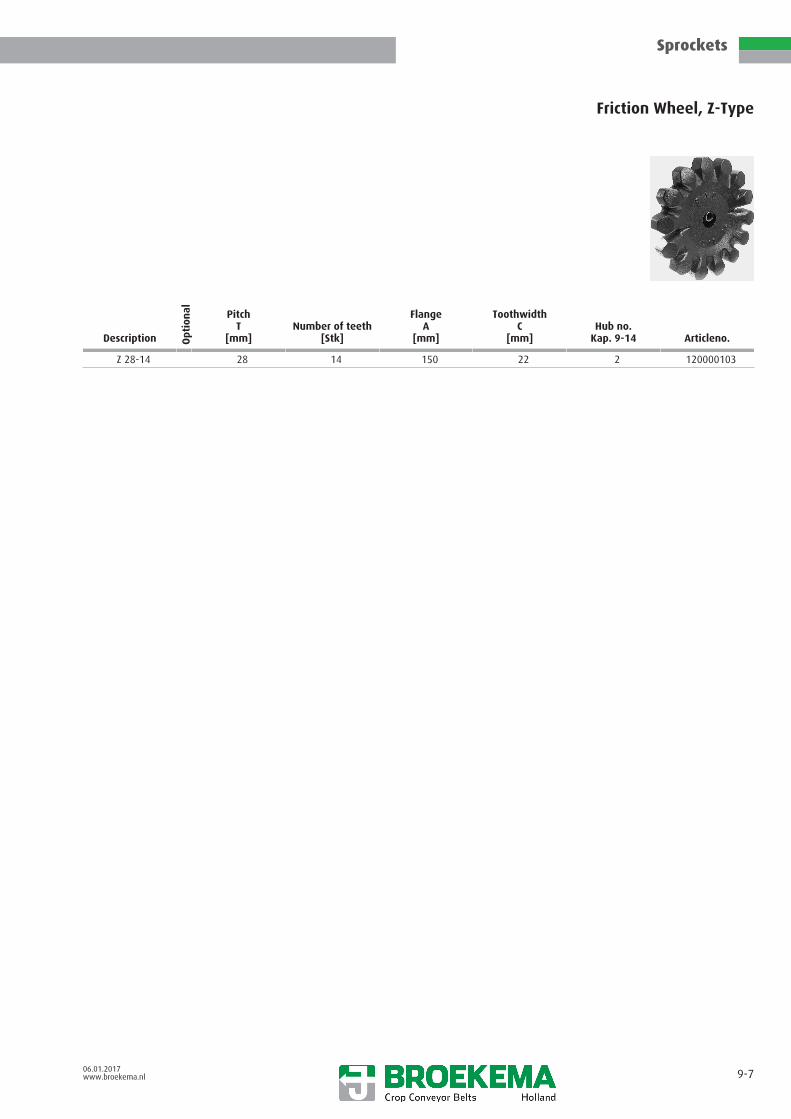
Sprockets
06.01.2017www.broekema.nl 9-7
Friction Wheel, Z-Type
Description Opt
ion
al PitchT
[mm]Number of teeth
[Stk]
FlangeA
[mm]
ToothwidthC
[mm]Hub no.
Kap. 9-14 Articleno.
Z 28-14 28 14 150 22 2 120000103

Sprockets
06.01.2017www.broekema.nl 9-8
Friction Wheel, ZP-Type
Description Opt
ion
al PitchT
[mm]Number of teeth
[Stk]Diameter
[mm]
WidthB
[mm] Articleno.
ZP 32-12 complete30 mm bore
32 12 157 22 120001296
ZP 32-14 complete30 mm bore
32 14 157 22 120001318
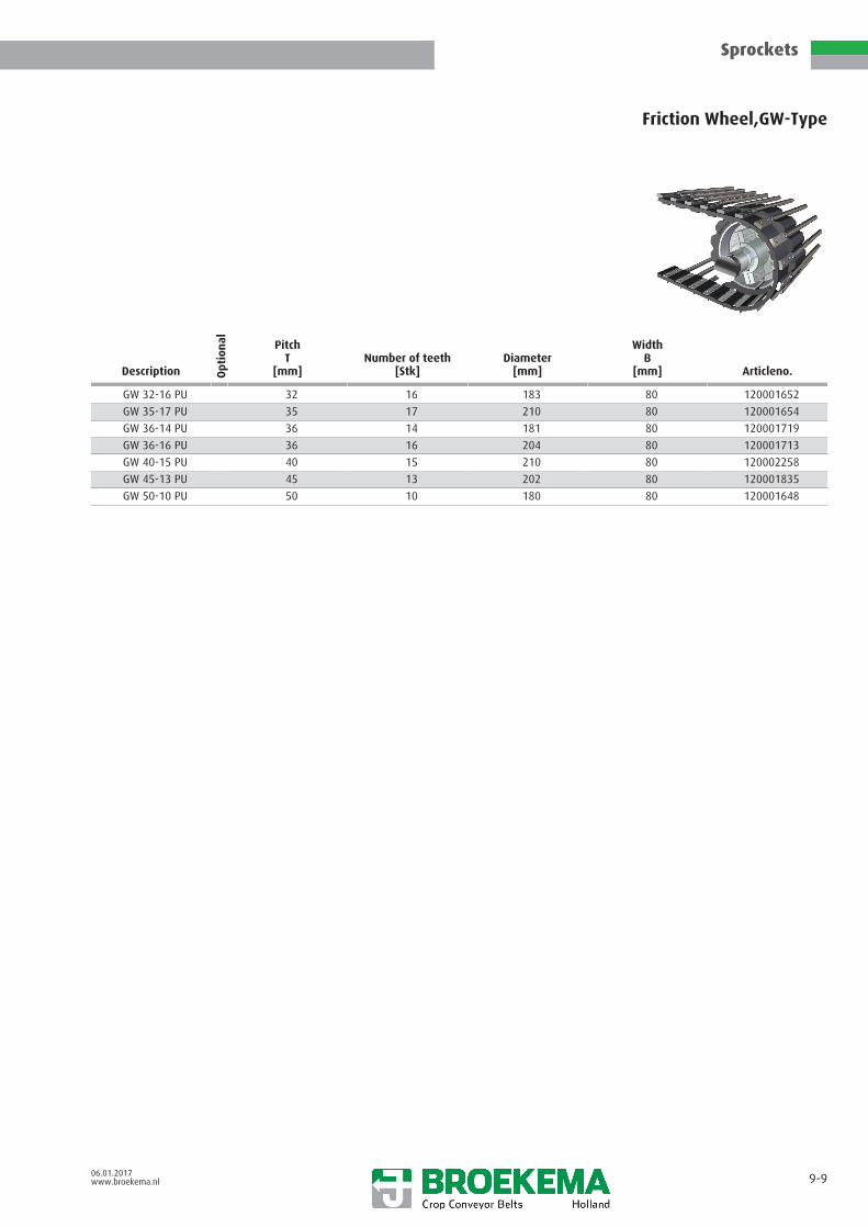
Sprockets
06.01.2017www.broekema.nl 9-9
Friction Wheel,GW-Type
Description Opt
ion
al PitchT
[mm]Number of teeth
[Stk]Diameter
[mm]
WidthB
[mm] Articleno.
GW 32-16 PU 32 16 183 80 120001652
GW 35-17 PU 35 17 210 80 120001654
GW 36-14 PU 36 14 181 80 120001719
GW 36-16 PU 36 16 204 80 120001713
GW 40-15 PU 40 15 210 80 120002258
GW 45-13 PU 45 13 202 80 120001835
GW 50-10 PU 50 10 180 80 120001648

Sprockets
06.01.2017www.broekema.nl 9-10
Duratec drive wheel
Description Opt
ion
al
Pitch[mm]
Number of teeth[Stk]
Diameter[mm]
WidthB
[mm]
Duratec 22.5-28 22,5 28 192,4 20
Duratec 36-16 36 16 207,1 30
Duratec 50-13 50 13 258,8 30
Duratec 56-14 56 14 289 30
Duratec wheel is modular. More versions possible, please ask our technical department

Sprockets
06.01.2017www.broekema.nl 9-11
Friction Wheel, KW-Type
Description Opt
ion
al FlangeA
[mm]
Cage diameterB
[mm]
ToothwidthC
[mm]
Finger lengthD
[mm]
DiameterK
[mm] Articleno.
KW 80 125 80 10 45 20-25 120000107
KW 100 150 100 10 60 20-30 120000108
KW 115 165 115 10 60 20-30 120000109
KW 160 (*) 215 160 10 60 25-40 120000110
* splittable for easy mounting

Sprockets
06.01.2017www.broekema.nl 9-12
Friction-driving wheel, HS-Type
Description Opt
ion
al diameter ØD
[mm]
FlangeA
[mm]
WidthB
[mm]
Support widthC
[mm]
Bore Ømin.-max.
[mm] Articleno.
HS 11 R 110 148 62 53.5 25 - 50 121000112
HS 11 RZ 110 62 62 25 - 50 121000113
HS 14 R 140 180 67 56.5 25 - 50 121000114
HS 14 RZ 140 67 67 25 - 45 121000115
HS 18 180 240 65 65 25 - 50 121000116
HS 18 R 180 248 67 57 25 - 45 121000117
HS 18 Z 180 65 65 25 - 50 121000119
HS 18 RZ 180 67 67 25 - 50 121000118
HS 21 210 300 70 58,5 25 - 50 121000120
HS 21 R 210 240 75 65 25 - 50 121000121
HS 21 RZ 210 65 65 25 - 50 121000122
HS 24 R 240 300 70 58.5 25 - 50 121000123
HS 24 RZ 240 65 65 25 - 50 121000124
HS 41 R 410 448 89 63.5 25 - 50 121000125

Sprockets
06.01.2017www.broekema.nl 9-13
Friction-driving wheel, FRD-Type
Description Opt
ion
al diameter ØD
[mm]
FlangeA
[mm]
WidthB
[mm]
Support widthC
[mm]
Bore Ømin.-max.
[mm] Articleno.
FRD 14 R 140 180 125 56 25 - 45 12000601
FRD 14 RZ 140 125 64 25 - 45 120001000
FRD 18 R 180 220 131 60 25 - 50 120000127
FRD 18 RZ 180 131 68 25 - 50 120000838
FRD 20 R 200 260 155 80 25 - 50 120000128

Sprockets
06.01.2017www.broekema.nl 9-14
Hubs
Description Opt
ion
al
Hub no.Kap. 9-14
Hub lenghtE
[mm]
HeightG
[mm]
HeightH
[mm]
HeightJ
[mm]
DiameterK
[mm] Articleno.
Hubs 1 63 90 58 33 25-40
Hubs 2 60 100 65 40 25-40
Hubs 3 61 120 85 43 35-60
Hubs 4 30 100 60 40 25-40
Hubs 5 60 130 80 40 35-60

06.01.2017www.broekema.nl 9-15

Rollers
06.01.2017www.broekema.nl 10-0
General information 10- 1
Light weight rollers 10- 2
PVC rollers, NP 10- 3
PVC rollers 10- 4
Nylon roller without flange 10- 5
Nylon roller with flange 10- 6
Cast iron rollers, HS-type 10- 7
Cast iron roller 10- 8
Cast iron rollers vulcanized, HS-type 10- 9
Cast iron roller vulcanized 10-10
Shaker/Agitator 10-11
Ball-bearings 10-12
Securing ring 10-13
Felt rings 10-14
Dustcaps 10-15
Seals and filling rings 10-16

Rollers
06.01.2017www.broekema.nl 10-1
General information: Belt support rollers
We offer a wide range of support rollers suited for any kind of conveyor application. Please ask, if you are looking for a roller notincluded here.
A roller’s surface may be plain base material like nylon, urethane or cast metal. It can also be lined with rubber.
An axle’s shoulder length can be specified to position the roller under the rods or to compensate for distance variation from thesecuring point.
Roller types with a vulcanized rubber layer are usually placed in return/carry back positions to prevent rivet head and rod end wear.
A light duty roller can be defined as without bearing or with a single bearing. It must not be confused with light weight rollers. Itsfunctioning is usually only satisfactory if a dual bearing roller types are fitted at all conveyor angle or directional changes.
Cast iron is used as core/hub material of the HS roller line.
A triple seal system is incorporated in the HS roller line: An outer metal cover seal, an oiled felt filler ring and 2 bearings sealed onboth sides. Optionally e.g. for beet & tomato juice compatibilty or similar fluids you may specify Vulkolan or ZZ oil seal types. Highestquality 6005 2RS and 6206 2RS ball bearings are used in the HS-line as standard.
Our heavy duty, light weight rollers of the PA-roller line are completely grease filled for lifetime and sealed off with mulitplelabyrinth type seals. They have been very succesfully used in heavy duty harvesting applications for many years.
Flanged and non-flanged versions of the HS-and PA-roller lines are available.
An S type roller is narrower for elevators with flights, allowing maximum flight length. Bolt head intrusion is avoided if you specify athreaded axle.
Greasable roller versions: Only possible with threaded spindle/axle and nut & lock washer. Axle length can vary to your specification.Contains open sided bearings with internal grease chamber reservoir. A metal seal cap covers one end and the open flange side capallows excess grease to escape. Greasable rollers are fitted with Nilos type seals and the steel caps are retained by expanding snaprings. They are suited to hand or auto-lube applications.
Threaded axles: Standard thread size M16 (5/8”), M18 (11/16”) or M20 (25 mm spindle O.D.) are optional.
Open bore axles: Standard thread size M16 (5/8”), M18 (11/16”) or M20 (25 mm spindle O.D.) are optional.
General information: Shakers/agitation systems
Shakers are available in cast iron and rubber.
The triangular shape offers a good eccentricity effect. The peripheral speed of the shaker is relative to the belt speed.
Cast iron shaker types are designed to be rod driven. They are therefore rod pitch related and need positioning in the sprocket runarea. Careful alignment is needed if the rods of a belt are cranked.
The rubber type shakers are positioned under the belting. They are pitch independent.
Belt width determines the axle stand-off/shoulder length. Please specify when ordering.
All types contain dual bearings with our standard triple seal system as in HS type rollers, only the axle length differs. Shakers areusually ordered as open bore for a M16 or M18 bolt.
Centrally mounted pairs of shakers need to be mounted with long, high tensile strength bolts which must be capable of high shockstresses.
High frequency agitation with less vertical movement can also be achieved by mounting a pair of non flanged, rubber covered rollersunder the conveyor’s sprocket run area. They may be fitted to height adjustable arms for variable effect, or in a fixed position. Thedegree of movement is regulated by the roller diameter, rod diameter and rod pitch. These rollers may also be incorporated in apower driven shaker system where they are mounted onto arms with a reciprocating vertical motion relative to the conveyor´smoving plane.
Half round nylon blocks (at your specified distance) instead of rivet retaining plates can be fitted to the conveyor. This is another(fixed frequency) agitation method. They are usually used with low profile belting, exposing only 4 mm of their 8 mm thickness.Such conveyors are best supported by rubber covered rollers.
Conveyor agitation should not be located at any change in angle, e.g. a pivot point, because any extra belt tautness would create anundesired ‘dampening’ effect.

Rollers
06.01.2017www.broekema.nl 10-2
Light weight rollers
Description Opt
ion
al
Position
diameter ØD
[mm]
WidthB
[mm] MaterialDesign
ball-bearing Articleno.
VRR 7537 2 75 37 rubber with 121000104
HS G1 65 30 cast iron with / without 121000102
HS G1 R 75 30 cast iron & rubber with / without 121000893
KR 9 SZ 90 29 Nylon/rubber with / without 121000731
PA 10 * 106 27 Plastic / Synthetic with
HS 8 PUSZ 80 43,5 Polyurethan with 121000978

Rollers
06.01.2017www.broekema.nl 10-3
PVC rollers, NP
Description Opt
ion
al diameter ØD
[mm]
Flange ØA
[mm]
WidthB
[mm]
Support widthC
[mm]Design ball-
bearing Articleno.Weight
[Kg]
NPK 75 NF 75 115 61,5 50 6005 2RS1 121000106 0,48
NPK 75 Z 75 75 61,5 61,5 6005 2RS1 121000107 0,48
NPK 90 NF 90 130 61,5 50 6005 2RS1 121000949 0,61
NPK 90 Z 90 61,5 61,5 6005 2RS1 121000950 0,58
SF = Steel flangeNF = Nylon flangeZ = without flangeNPK = Nylon body covered with PU, carvedNP = Nylon body covered with PU

Rollers
06.01.2017www.broekema.nl 10-4
PVC rollers
Description Opt
ion
al diameter ØD
[mm]
Flange ØA
[mm]
WidthB
[mm]
Support widthC
[mm] Articleno.
PA 60 ZL 60 60 60 60 121000117
PA 100 ZL 60 100 60 60 121000119
PA 9 R 90 132 65 56
PA 9 RZ 90 65 65
PA 9 RH 90 132 65 56
PA 9 RZH 90 65 65
PA 9 RM 90 132 65 56
M = with threaded axleH = Thorough open boreZ = without flangeR = rubber-covering

Rollers
06.01.2017www.broekema.nl 10-5
Nylon roller without flange(possible design)
Description Opt
ion
al
Position
diameter ØD
[mm]
Support widthC
[mm]
DistanceE
[mm]FF Articleno.
Rollers * 1 90 65 4,5 M16 x 60 121001147
Rollers * 1 90 65 4,5 M16 x 40 121001106
Rollers * 1 90 65 4,5 M16 x 60 121001107
Rollers 2 90 65 4 Ø 16,5 121000855
Rollers 2 90 65 4,5 Ø 16,5 121000004
Rollers 3 90 65 4 Ø 16,5 121000896
Rollers * 3 90 65 - Ø 16,5 -
Rollers * 3 90 65 - -
Rollers * 2 90 89 4,5 121001418

Rollers
06.01.2017www.broekema.nl 10-6
Nylon roller with flange(possible design)
Description Opt
ion
al
Position
diameter ØD
[mm]
Flange ØA
[mm]
WidthB
[mm]
DistanceE
[mm]FF Articleno.
Rollers 2 90 132 65 4 Ø 16,5 121000854
Rollers 3 90 132 65 4 Ø 16,5 121001096
Rollers 3 90 132 65 4 Ø 16,5 121001097
Rollers 3 90 132 65 121000866
Rollers 2 90 132 65 4,5 Ø 16,5 121001100
Rollers 1 90 132 65 4,5 M16 x 40 121000870
Rollers 1 90 132 65 4,5 M16 x 60 121001105
Rollers * 2 90 132 65 4,5 Ø16,5 77010000638
Rollers * - 90 132 89 Ø 16,5 121001101

Rollers
06.01.2017www.broekema.nl 10-7
Cast iron rollers, HS-type
Description Opt
ion
al diameter ØD
[mm]
Flange ØA
[mm]
WidthB
[mm]
Support widthC
[mm] Articleno.
HS 6 62 100 61,5 53 121000063
HS 6 Z 62 61,5 61,5 121000065
HS 6 SZ 62 43,5 43,5 121000064
HS 8 80 120 61,5 52 121000066
HS 8 80 120 65
HS 8 Z 80 61,5 61,5 121000070
HS 9 WBR * 90 130 90 70 121000076
HS 10 100 136 75 63
HS 10 100 135 75 63 121000078 / 79
HS 10 Z 100 75 75 121000083 / 84
HS 10 H 100 180 61,5 50 121000077
HS 10 WDR 100 150 61,5 46 121000082
HS 11 110 150 67 54 121000086 / 87
HS 11 Z * 110 67 67
HS 15 150 250 67 60 121000096
HS 15 Z * 150 67 67
HS 18 180 220 61,5 50 121000097 / 98
HS 18 Z * 180 61,5 61,5
H = high flangeS = small support widthZ = without flange

Rollers
06.01.2017www.broekema.nl 10-8
Cast iron roller(possible design)
Description Opt
ion
al
Position
diameter ØD
[mm]
Flange ØA
[mm]
WidthB
[mm]
DistanceE
[mm]FF Articleno.
Rollers * 4 90 126 75 4 M24 x 40
Rollers 2 100 136 75 4 Ø 20,5 121001098
Rollers 2 100 136 75 4 Ø16,5 121001094

Rollers
06.01.2017www.broekema.nl 10-9
Cast iron rollers vulcanized, HS-type
Description Opt
ion
al diameter ØD
[mm]
Flange ØA
[mm]
WidthB
[mm]
Support widthC
[mm] Articleno.
HS 8 R 80 118 56,5 50 121000068
HS 8 RZ 80 61,5 61,5 121000069
HS 9 R * 90 130 50
HS 9 R 90 130 61,5 54 121000071
HS 9 RZ 90 61,5 61,5 121000075
HS 9 RSZ 90 43,5 43,5 121000074
HS 9 RS 90 130 43,5 35 121000073
HS 9 RH 90 200 67 59 121000072
HS 10 R 100 140 67 55 121000080
HS 10 RZ 100 67 67 121000081
HS 11 R 110 148 62 53,5 121000088/801
HS 11 R 110 150 75
HS 11 R 110 165 75
HS 11 RS 110 148 46,5 42,5 121000089
HS 11 RZ 110 62 62 121000091/92
HS 14 R 140 180 67 56,5 121000093
HS 14 RZ 140 67 67 121000094/95
HS 18 R 180 248 67 57 121000099
HS 18 RZ 180 67 67 121000100
HS 21 R 210 240 75 65 121000101
H = high flangeZ = without flangeS = small support widthR = rubber-covering

Rollers
06.01.2017www.broekema.nl 10-10
Cast iron roller vulcanized(possible design)
Description Opt
ion
al
Position
diameter ØD
[mm]
Flange ØA
[mm]
WidthB
[mm]
DistanceE
[mm]FF Articleno.
Rollers * 2 90 130 50 11 M16 x 52 121000699
Rollers 1 110 150 75 4 Ø 20,5 121000862
Rollers 1 110 165 75 4 Ø 20,5 121000748
Rollers 4 100 - 66 4 Ø 16,5 121001269
Rollers 1 110 165 86 4 Ø 20,5 121000916

Rollers
06.01.2017www.broekema.nl 10-11
Shaker/Agitator
Description Opt
ion
al PitchT
[mm]
diameter ØD
[mm] Eccentricity
WidthB
[mm] Articleno.
HSA 28 28 190 32 61,5 121000125
HSA 32 32 / 33 190 32 61,5 121000126
HSA 36 36 170 37 61,5 121000127
HSA 42 42 195 35 61,5 121000128
USS 45 45 212 40 61,5 121000130
USS 50 50 232 42 61,5 121000131Universal
Shaker/AgitatorAll pitches 175 30 61,5 121000124/129

Rollers
06.01.2017www.broekema.nl 10-12
Ball-bearings(Parts)
Description Opt
ion
al Outside ØD
[mm]
Inner Ød
[mm]
WidthB
[mm] Articleno.
6005 47 25 12 121001139
6005-Z 47 25 12 121000188
6005-2RS 47 25 12 121000187/757
6005-2RS-Stainless 47 25 12 121000654
6205-2RS-BING-ABEC 47 25 12 121001317
6006 1RS * 55 30 13 -
6206 * 62 30 16 -
6206 1RS 62 30 16 121001034
6206-2RS 62 30 16 121000189/759
6308-2RS 90 40 23 121000760
6005-1RS 47 25 1 121001033

Rollers
06.01.2017www.broekema.nl 10-13
Securing ring(Parts)
Description Opt
ion
al
Position
Outside ØD
[mm]Thickness material
[mm] Norm Articleno.
A 25 x 1,2 1 25 1,2 DIN 471 121000152
A 30 x 1,5 1 30 1,5 DIN 471 121000153
A35 1 35 1,5 DIN 471 121001041
J47 2 47 1,75 DIN 472 121000154
J55 2 55 2 DIN 472 121000857
J62 2 62 2 DIN 472 121001037
J65 2 65 2,5 DIN 472 121001043
J78 2 78 2,5 DIN 472 121001042/1039
J72 2 72 2,5 DIN 472 121001038
J80 2 80 2,5 DIN 472 121001040

Rollers
06.01.2017www.broekema.nl 10-14
Felt rings(Parts)
Description Opt
ion
al Outside ØD
[mm]
Inner Ød
[mm]
WidthB
[mm] Articleno.
Felt ring 44 24 7,5 121000179
Felt ring 44 24 4,5 121000178
Felt ring 44 30 7,5 121000180
Felt ring 58 30 6 121000181

Rollers
06.01.2017www.broekema.nl 10-15
Dustcaps(Parts)
Pos. 1 Pos. 2 Pos. 3
Description Opt
ion
al
Position
Outside ØD
[mm]
Inner Ød
[mm]Thickness material
[mm] Articleno.
Closed metal dust cap 1 47 121000169
Closed metal dust cap 1 62 121000170Open centre
metal dust cap2 47 25 121000174
Open centremetal dust cap
2 47 30 121000175
Open centremetal dust cap
2 62 30 121000176
Metal convex ring 3 47 25 1,5 121000155
Metal convex cap 4 47 1,5 121000156
Metal filling ring 47 121000182

Rollers
06.01.2017www.broekema.nl 10-16
Seals and filling rings(Parts)
Description Opt
ion
al
Position
Outside ØD
[mm]
Inner Ød
[mm]
WidthB
[mm] Articleno.
Seal 2 65,5 30 4 121001044
Seal 2 121001069
Seal 2 70 31 3 121001035
Seal 2 121001068
Seal 2 121001067
Fill-ring 2 72 56 2,0 121001070
Seal Z 005 1 47 25 5 121000841
Seal Z 005 F 47 25 5 121000183
Seal Z 006 1 55 30 5 121000849
Seal Z 206 1 62 30 6 121000837
Seal Z 206 F 62 30 6 121000879
Seal Z 207 72 35 6 121000838
Seal Z 207 F 72 35 6 121000185
Seal Z 210 F 90 50 6 121000186
Fill-ring 2 65 52 1,6 121001049
Fill-ring 2 42 30 1,5 121001050
Seal 2 121001064
Fill-ring 2 45 35 0,3 121001046
Fill-ring 2 45 35 1,5 121001047
Fill-ring 2 45 35 2,5 121001048
Oil seal 47 30 7 121001399

Rivets & plates
06.01.2017www.broekema.nl 11-0
General information 11- 1
Rivet retaining plates 11- 2
Threaded plates 11- 3
Set for lapjoint 11- 4
Rivets according to DIN 661 11- 5
Rivets with tapered ends 11- 6
2-phase rivets 11- 7
Rivets according to DIN 661 11- 8
Flat headed rivets DIN 675 11- 9
Flat headed 2-phase rivets 11-10
Half round cylindrical block 11-11

Rivets & plates
06.01.2017www.broekema.nl 11-1
General information
Rivets are formed to fit into the countersunk holes of the rivet retaining plates & rivet rods. They conform to the German DIN 661steel standard. Their length differs in relationship to the combined thickness of the plate, belt and rod.
Our tapered rivets facilitate rod mounting tremendously.
Rivet retaining plates help to create the maximum sandwich compression effect of the belting and underside area of the rivetrod, yet designed to preserve belt flexibility. All our types are galvanization plated with a stamp coding. The first code number isthe centre to centre distance of the rivet holes in millimeters, the second is the rivet diameter in millimeters, (e.g. 32-5.5). All rivetretaining plate holes are countersunk to accept the rivet head.
Large flat headed rivets, conforming to the German DIN 675 steel standard, perform very well in light duty conveyors. Rivetretaining plates are not needed with this kind of rivet. They can be used with any kind of belting also in higher load applications!
Threaded plates are used in conjunction with M5 or M6 securing screws. They are used as an alternative fastening method usingsmall ´Nylon’ self securing nuts. The screw´s head locates into the countersunk holes in the upper rod surface, the screw passesthrough the rod & belt and threads into the threaded plate. The head has a socket wrench recess for screw tightening purposes.Excess screw length must be cut away or ground down so as not to conflict with the fingers of cage drive systems and roller surfaces.
Lapjoints fitted with threaded plates is a good joint combination. Such threaded plates may also be used when replacing rivet rodsor on certain rods for a new belt assembly, e.g. where to retrofit flights etc.. Threaded plates reduce crop damage compared to thenut and bolt securing method.
Half round nylon blocks may be fitted at the time of manufacture under a low profile belting type conveyor in place of rivetretaining plates. Their spacing controls agitation frequency. They lay 4 mm above the level of low profile belting. Normally they areonly fitted to light duty sieving conveyors with 50 mm wide belting.

Rivets & plates
06.01.2017www.broekema.nl 11-2
Rivet retaining plates
Description Opt
ion
al Hole DistanceLA
[mm]
LengthL
[mm]
WidthB
[mm]
Thicknesst
[mm]
Hole ØD
[mm]
Rivet ØND
[mm] Articleno.
Rivetretaining plate
- 26 13 2,5 5,4 5,0 123000001
Rivetretaining plate
- 26 13 2,5 6,4 6,0 123000002
Rivetretaining plate
20 37 13 2,5 5,4 5,0 123000003
Rivetretaining plate
20 37 13 2,5 6,4 6,0 123000067
Rivet retainingplate stainless
20 37 13 2,5 5,4 5,0 123000062
Rivetretaining plate
20 46 15 3 6,4 6 123000011
Rivetretaining plate
20 46 13 2,5 5,4 5,0 123000005
Rivetretaining plate
20 46 15 2,5 6,4 6 123000007
Rivet retainingplate stainless
20 46 13 2,5 5,4 5,0 123000006
Rivetretaining plate
20 46 13 2,5 6,4 6,0 123000068
Rivetretaining plate
24 34,5 13 2,5 6,0 5,5 -
Rivetretaining plate
24 37 13 2,5 6,4 6,0 123000073
Rivetretaining plate
24 37 13 2,5 5,4 5,0 123000004
Rivetretaining plate
24 45 13 2,5 6,0 5,5 123000084
Rivetretaining plate
24 46 13 2,5 6,4 6,0 123000069
Rivetretaining plate
24 46 13 2,5 5,4 5,0 123000008
Rivetretaining plate
24 46 13 2,5 6,4 6,0 123000069
Rivetretaining plate
24 46 13 2,5 6,0 5,5 123000084
Rivetretaining plate
30 56 15 3 6,4 6 123000011
Rivetretaining plate
30 56 13 2,5 6,4 6,0 123000037
Rivetretaining plate
30 56 13 2,5 6,0 5,5 123000010
Rivetretaining plate
30 56 13 2,5 6,4 6,0 123000037
Rivetretaining plate
30 56 13 2,5 5,4 5,0 123000009
Rivetretaining plate
30 56 15 3 6,4 6 123000011
Rivet retainingplate stainless
32 56 13 2,5 6,0 5,5 123000015

Rivets & plates
06.01.2017www.broekema.nl 11-2 b
Description Opt
ion
al Hole DistanceLA
[mm]
LengthL
[mm]
WidthB
[mm]
Thicknesst
[mm]
Hole ØD
[mm]
Rivet ØND
[mm] Articleno.
Rivet retainingplate stainless
32 56 13 2,5 5,4 5,0 123000013
Rivetretaining plate
32 56 15 3 6,4 6,0 123000016
Rivetretaining plate
32 56 13 2,5 6,0 5,5 123000014
Rivetretaining plate
32 56 20 2,5 11 123000116
Rivetretaining plate
32 56 13 2,5 5,4 5,0 123000012
Rivetretaining plate
32 56 13 2,5 6,4 6,0 123000017
Rivetretaining plate
32 62 15 3 6,4 6 123000018

Rivets & plates
06.01.2017www.broekema.nl 11-3
Threaded plates
Description Opt
ion
al
Belting width[mm]
Hole DistanceLA
[mm]
LengthL
[mm]
WidthB
[mm]Thread
D Articleno.
20 M5 40 20 37 14 M5 123000053
20 M5 50 20 46 14 M5 123000020
20 M6 40 20 37 14 M6 123000054
20 M6 50 20 46 14 M6 123000022
20 M6 60 20 56 14 M6 123000021
24 M5 50 24 46 14 M5 123000023
30 M5 60 30 56 14 M5 123000024
32 M5 60 32 56 14 M5 123000027
30 M6 60 30 56 15 M6 123000025
32 M6 60 32 56 15 M6 123000028
32 M8 60 32 56 15 M8 123000030
UNF 12/28 60 32 56 14 UNF 12/28 123000060

Rivets & plates
06.01.2017www.broekema.nl 11-4
Set for lapjoint
Description Opt
ion
al
Belting width[mm]
Hole distance[mm]
Thread[mm] Number of plates Number of bolts Articleno.
20 M5 40 20 M5 6 12 123000055
20 M5 50 20 M5 6 12 123000034
32 M5 60 32 M5 6 12 123000038
32 M6 60 32 M6 6 12 123000035
20 M5 50 20 M5 7 14 123000146
20 M6 50 20 M6 7 14 123000148
30 M5 60 30 M5 7 14 123000147
30 M6 60 30 M6 7 14 123000149

Rivets & plates
06.01.2017www.broekema.nl 11-5
Rivets according to DIN 661(Ø 4,0 / 5,0 / 5,5 / 6,0)
Description Opt
ion
al DiameterD
[mm]
LengthL
[mm] Articleno.
Rivet 4 16 122000259
Rivet 4 19 122000260
Rivet 5 14 122000261
Rivet 5 21 122000264
Rivet 5 22 122000265
Rivet 5 33 122000014
Rivet 5 34 122000015
Rivet 5 35 122000016
Rivet 5,5 25 122000266
Rivet 5,5 27 122000025
Rivet 5,5 29 122000267
Rivet 5,5 31 122000268
Rivet 6 17 122000269
Rivet 6 18 122000270
Rivet 6 19 122000271
Rivet 6 28 122000273

Rivets & plates
06.01.2017www.broekema.nl 11-6
Rivets with tapered ends(Ø 5,0 / 5,5 / 6,0)
Description Opt
ion
al DiameterD
[mm]
LengthL
[mm] Articleno.
Rivet 5 18 122000032
Rivet 5 19 122000033
Rivet 5 20 122000034
Rivet 5 21 122000035
Rivet 5 22 122000036
Rivet 5 23 122000037
Rivet 5 24 122000038
Rivet 5 25 122000039
Rivet 5 26 122000040
Rivet 5 28 122000042
Rivet 5 30 122000043
Rivet 5 32 122000044
Rivet 5,5 18 122000285
Rivet 5,5 21 122000286
Rivet 5,5 22 122000287
Rivet 5,5 24 122000050
Rivet 5,5 26 122000051
Rivet 5,5 28 122000052
Rivet 5,5 30 122000053
Rivet 5,5 32 122000054
Rivet 6 20 122000130
Rivet 6 21 122000055
Rivet 6 22 122000056
Rivet 6 23 122000057
Rivet 6 24 122000058
Rivet 6 25 122000059
Rivet 6 26
Rivet 6 23 122000293
Rivet 6 28 122000295
Rivet 6 29 122000142
Rivet 6 30 122000061

Rivets & plates
06.01.2017www.broekema.nl 11-7
2-phase rivets
Description Opt
ion
al DiameterD
[mm]
LengthL
[mm] Articleno.
2-phase rivet 5 17 122000180
2-phase rivet 5 18 122000181
2-phase rivet 5 19 122000182
2-phase rivet 5 20 122000183
2-phase rivet 5 21 122000184
2-phase rivet 5 22 122000185
2-phase rivet 5 23 122000186
2-phase rivet 5 24 122000187
2-phase rivet 5 25 122000188
2-phase rivet 5 26 122000189
2-phase rivet 5 27 122000190
2-phase rivet 5 28 122000191
2-phase rivet 5 30 122000192
2-phase rivet 5 32 122000193
2-phase rivet 5 33 122000194
2-phase rivet 5 34 122000195
2-phase rivet 5 35 122000196
2-phase rivet 5,5 18 122000197
2-phase rivet 5,5 20 122000198
2-phase rivet 5,5 21 122000199
2-phase rivet 5,5 22 122000200
2-phase rivet 5,5 23 122000201
2-phase rivet 5,5 24 122000202
2-phase rivet 5,5 25 122000203
2-phase rivet 5,5 26 122000204
2-phase rivet 5,5 27 122000205
2-phase rivet 5,5 28 122000206
2-phase rivet 5,5 30 122000207
2-phase rivet 5,5 32 122000208

Rivets & plates
06.01.2017www.broekema.nl 11-8
Rivets according to DIN 661(Ø 5,0 / 6,0) in stainless steel
Description Opt
ion
al DiameterD
[mm]
LengthL
[mm] Articleno.
Rivet 5 16 122000002
Rivet 5 18 122000005
Rivet 5 19 122000006
Rivet 5 20 122000007
Rivet 5 21 122000008
Rivet 5 22 122000009
Rivet 5 25 122000012
Rivet 6 19 122000272

Rivets & plates
06.01.2017www.broekema.nl 11-9
Flat headed rivets DIN 675
Description Opt
ion
al DiameterD
[mm]
LengthL
[mm] Articleno.
Rivet 5 15 122000062
Rivet 5 18 122000064
Rivet 5 21 122000434
Rivet 5 25 122000066
Rivet 5 30 122000157
Rivet 5,5 15 122000274
Rivet 5,5 17 122000275
Rivet 5,5 20 122000276
Rivet 5,5 22 122000364
Rivet 5,5 30 122000157
Rivet 6 17 122000277
Rivet 6 20 122000278
Rivet 6 22 122000246

Rivets & plates
06.01.2017www.broekema.nl 11-10
Flat headed 2-phase rivets
Description Opt
ion
al DiameterD
[mm]
LengthL
[mm] Articleno.
Flat headed rivet 2-phase 5 15 122000233
Flat headed rivet 2-phase 5 16 122000224
Flat headed rivet 2-phase 5 18 122000225
Flat headed rivet 2-phase 5 20 122000226
Flat headed rivet 2-phase 5 22 122000234
Flat headed rivet 2-phase 5,5 18 122000427

Rivets & plates
06.01.2017www.broekema.nl 11-11
Half round cylindrical block
Description Opt
ion
al Hole DistanceLA
[mm]
LengthL
[mm]
WidthB
[mm]
Rivet ØND
[mm] Articleno.
Half roundcylindrical block
20 14 14 5 116000005

Moulded articles
06.01.2017www.broekema.nl 12-0
General information 12- 1
Rubber finger 12- 2
Haulmspring 12- 3
Sorting disk 12- 4
Flights 12- 5
Stars 12- 6
Distance keeper for Stars 12- 7

Moulded articles
06.01.2017www.broekema.nl 12-1
General information
This chapter gives you an overview of our plastic and rubber components which are especially designed for harvesting, cleaning,sorting and grading applications.
– Rubber and plastic vine finger covers for vine/trash separation belts. The protective caps slip over vertical metal fingersmounted/welded onto the rivet rods.
– Spring load flow resistance paddle for removing vine/trash– Disc type elements for sizing/grading spools– Star type elements for sizing/grading spools– 1-STAR® cleaning/trash removal elements for star rollers

Moulded articles
06.01.2017www.broekema.nl 12-2
Rubber finger
Pos. 1 Pos. 2 Pos. 3
Description Opt
ion
al
Position
Outside ØD
[mm]
Inner Ød
[mm]
LengthL
[mm] Material Articleno.
Rubber finger 1 24 8 80 SBR / BR 129000003
Rubber finger 1 24 8 110 SBR / BR 129000006
Rubber finger 2 25 8 78 129000004
Rubber finger 4 23 / 17,5 M8 70 129000009
Rubber finger 24 8 117
Rubber finger 30 / 17 M10 93 129000089

Moulded articles
06.01.2017www.broekema.nl 12-3
Haulmspring
Description Opt
ion
al WidthB
[mm]
LengthL
[mm] Material Articleno.
Haulmspring 60 296 NR / SBR 129000001
Haulmspring 110 296 NR / SBR 129000002
Haulmspring 110 296 NR / SBR 129000209

Moulded articles
06.01.2017www.broekema.nl 12-4
Sorting disk
Description Opt
ion
al
Position
Outside ØD
[mm]
Widthd
[mm]
WidthB
[mm]
Widths
[mm] Material Articleno.
Sorting disk 2 98 21 8 NR / SBR 129000118
Sorting disk 1 98 16 20 8 NR / SBR 121000143
Sorting disk 1 98 19 20 8 NR / SBR 121000144
Sorting disk 1 98 21 20 8 NR / SBR 121000145
Sorting disk 1 98 26 20 8 NR / SBR 121000146
Sorting disk 2 100 15,5 10 NR / SBR
Sorting disk 2 120 21 8 NR / SBR

Moulded articles
06.01.2017www.broekema.nl 12-5
Flights
Description Opt
ion
al Outside ØD
[mm]
Inner Ød
[mm]
Heights
[mm] Material Articleno.
Flight 98 25 77 NR / SBR

Moulded articles
06.01.2017www.broekema.nl 12-6
Stars
Description Opt
ion
al
Number of finger
Outside ØD
[mm]Square[mm]
Heights
[mm] Material Articleno.
Stars 6 162 24 38,5 NR / SBR 121000135
Stars 6 162 29 38,5 NR / SBR 121000136
Stars 6 162 32 38,5 NR / SBR 121000137
Stars 13 164 32
Stars 7 164 32
Stars 7 164 38
Stars 13 164 1-1/4" 32 NR / SBR 121000142
Stars 13 164 1-1/2" 32 NR / SBR 121001198
Stars 10 260 40 40 PU 121000872
Stars 10 260 40 40 PU 121000872
Stars 6 230 40 80 PU 121001130
Stars 13 170 30 32 PU 121000963
Stars 13 170 32 32 PU
Stars 13 170 38 32 PU
Stars 13 168 30 32 121000840

Moulded articles
06.01.2017www.broekema.nl 12-7
Distance keeper for Stars
Description Opt
ion
al
mould
Widthd
[mm]
WidthB
[mm] Articleno.
Distance keeper square 32 1/4”
Distance keeper square 32 3/8”
Distance keeper square 32 7/16”
Distance keeper square 32 1/2”
Distance keeper square 32 5/8”
Distance keeper square 38 1/4”
Distance keeper square 38 3/8”
Distance keeper square 38 7/16”
Distance keeper square 38 1/2”
Distance keeper square 38 5/8”

Spare parts
06.01.2017www.broekema.nl 13-0
rubber cleaner 13- 1
Side protection 13- 2

Spare parts
06.01.2017www.broekema.nl 13-1
rubber cleaner
Description Opt
ion
al WidthB
[mm]
LengthL
[mm] textile layers
Hole ØC
[mm] holes
rubber cleaner 40 260 4 10 1
rubber cleaner 40 260 10 10 1
rubber cleaner 40 225 10 10 1
rubber cleaner 40 300 10 10 2
rubber cleaner 60 80 10 12 1
rubber cleaner 80 255 10 12 2
rubber cleaner 80 255 10 12 2
rubber cleaner 80 255 10 12 2
rubber cleaner 80 270 15 10,5 2
rubber cleaner 80 360 15 10,5 2
rubber cleaner 80 175 15 7,5 2
rubber cleaner 80 185 15 10,5 2
rubber cleaner 30 190 0 9 2
rubber cleaner 30 328 smooth1,5:1,5 4
rubber cleaner 60 100 10 10 2
rubber cleaner 40 250 0 9/6 2
rubber cleaner 40 260 10 2
rubber cleaner 40 250 9/6 2
rubber cleaner 40 220 9/6 2
rubber cleaner * 125 188 8 10 2
rubber cleaner * 135 200 8 10 2
rubber cleaner * 150 200 8 10 2
rubber cleaner * 110 190 8 10 2
rubber cleaner 150 200 15 11 2
rubber cleaner * 60/105 240 8 10,5 2
rubber cleaner 80 165 15 15
rubber cleaner 56 270 15 15
rubber cleaner 80 210 15 15 2
rubber cleaner 120 200 17 2
rubber cleaner 40 153,9 15
rubber cleaner 145
rubber cleaner 30 120 5
rubber cleaner 80 240 15 15 2
rubber cleaner 80 240 8 15 2
rubber cleaner 50 515 3
rubber cleaner 80 185 15 2
rubber cleaner 150 200 15 2
rubber cleaner 40 260 1 2
rubber cleaner 120 235 15 9/6 2

Spare parts
06.01.2017www.broekema.nl 13-2
Side protection
Description Opt
ion
al HeightH
[mm]
WidthB
[mm] Articleno.
side protection 153 32 119001904