Embed Size (px)
Citation preview

FRevision A
February 2004
Guide for AgGPS ReceiversAgRemote Software

Corporate OfficeTrimble Navigation LimitedAgriculture Business Area9290 Bond Street, Suite 102Overland Park, KS 66214USA+1-913-495-2700 [email protected]
Copyright and Trademarks© 2004, Trimble Navigation Limited. All rights reserved.Trimble, the Globe & Triangle logo, and AgGPS are trademarks of Trimble Navigation Limited, registered in the United States Patent and Trademark Office and other countries.
Microsoft and Windows are either registered trademarks or trademarks of Microsoft Corporation in the United States and/or other countries.
All other trademarks are the property of their respective owners.
Release NoticeThis is the February 2004 release (Revision A) of the AgRemote Software Guide for AgGPS Receivers.

ContentsIntroduction . . . . . . . . . . . . . . . . . . . . . . . . . . . . . . . . . 4Downloading and Installing AgRemote . . . . . . . . . . . . . . . . . . 5
Downloading the install software from the Web . . . . . . . . . . . . . . 5Installing the software in your computer . . . . . . . . . . . . . . . . . . 7
Starting AgRemote . . . . . . . . . . . . . . . . . . . . . . . . . . . . . 7AgRemote Keys . . . . . . . . . . . . . . . . . . . . . . . . . . . . . . . 9Navigating Menus and Screens . . . . . . . . . . . . . . . . . . . . . . . 10
Fields . . . . . . . . . . . . . . . . . . . . . . . . . . . . . . . . . . . . . . . 13Positioning Mode . . . . . . . . . . . . . . . . . . . . . . . . . . . . . . 15
General GPS position information . . . . . . . . . . . . . . . . . . . . . . 16Configuring the Receiver . . . . . . . . . . . . . . . . . . . . . . . . . . 21
Display Options . . . . . . . . . . . . . . . . . . . . . . . . . . . . . . . . . 21Configuring the Communication Ports. . . . . . . . . . . . . . . . . . . . 24Configuring input / output communication . . . . . . . . . . . . . . . . . 27Configuring Differential GPS. . . . . . . . . . . . . . . . . . . . . . . . . 31OmniSTAR . . . . . . . . . . . . . . . . . . . . . . . . . . . . . . . . . . . 32WAAS/EGNOS . . . . . . . . . . . . . . . . . . . . . . . . . . . . . . . . . 34
Configuring the Receiver to Operate in RTK Mode . . . . . . . . . . . . 35Configuring Beacon DGPS . . . . . . . . . . . . . . . . . . . . . . . . . 36Installing Passcodes . . . . . . . . . . . . . . . . . . . . . . . . . . . . . 39Navigation Maps . . . . . . . . . . . . . . . . . . . . . . . . . . . . . . 40
AgRemote Software 3

Introduction
2.1 IntroductionThis document describes how to set up and begin using the AgRemote software. It includes an overview of the AgGPS® menu system.
The AgRemote software provides an interface that you can use to access the internal AgGPS menu system. Use the AgRemote menus and screens to configure the receiver settings and review the receiver status. To view the entire AgGPS menu system, see the AgRemote navigation maps document for your receiver firmware, on the Trimble website: www.trimble.com.
4 AgRemote Software

Downloading and Installing AgRemote
2.2 Downloading and Installing AgRemoteAgRemote requires Microsoft® Windows® 95, 98, Me, Windows 2000, or XP.
Note – Later versions of the AgRemote software may not install correctly under Windows 95.
22.1 Downloading the install software from the Web
Note – Some buttons and dialogs described in this procedure appear differently in different versions of Windows. Their functions and the steps to follow remain the same.
1. Go to www.trimble.com/agremote.html.
Click Download it now.
You are prompted to run the install program over the Web or download the install software to your computer.
2. Select Save this program to disk.
3. Click OK.
AgRemote Software 5

Downloading and Installing AgRemote
4. Choose a folder on the hard drive of your computer.
5. Click Save.
The AgRemote install software is downloaded from the website to your computer.
20.1 Installing the software in your computer
1. In Windows Explorer, double-click the AgRemote install software file you downloaded earlier.
The InstallShield message appears:
2. Click Yes.
3. The InstallShield Setup window appears. Follow the prompts to install the AgRemote software.
6 AgRemote Software

Starting AgRemote
2.1 Starting AgRemote1. Using the correct receiver cable, connect the receiver to the
serial port on the computer.
2. Connect a power supply to the receiver.
3. Turn on the receiver.
4. Select / Programs / AgRemote / AgRemote.
The AgRemote window appears.
5. Select File / Connect.
The Port Settings dialog appears.
6. Make sure that the Comm Port field is set to the port to which you have connected the receiver.
7. Click OK.
AgRemote establishes communication with the receiver and displays the Home screen of the AgGPS menu system.
AgRemote Software 7

Starting AgRemote
Figure 1 shows the AgRemote window, the Home screen, and the navigation keys.
Figure 1 AgRemote window, Home screen, and navigation keys
D 3D SV08 DOP02
S 1554.4970 S/N 10
Home screen
Right Down Up Enter
Keys
Left Esc
8 AgRemote Software
AgRemote Keys
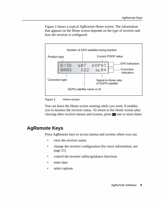
Figure 2 shows a typical AgRemote Home screen. The information that appears on the Home screen depends on the type of receiver and how the receiver is configured.
Figure 2 Home screen
You can leave the Home screen running while you work. It enables you to monitor the receiver status. To return to the Home screen after viewing other receiver menus and screens, press 5 one or more times.
2.1 AgRemote KeysPress AgRemote keys to access menus and screens where you can:
• view the receiver status
• change the receiver configuration (for more information, see page 21)
• control the receiver utility/guidance functions
• enter data
• select options
D/3D í07 DOP03WAAS 122 ÷ø04
Correction type
DGPS satellite name or ID
Signal-to-Noise ratioof DGPS satellite
GPS indicators
Correction
Current PDOP valuePosition type
Number of GPS satellites being tracked
indicators
AgRemote Software 9

Navigating Menus and Screens
The action associated with each of the AgRemote keys depends on whether a menu or a screen is displayed. See Table 1.
2.2 Navigating Menus and ScreensAgRemote uses menus and sub-menus to organize configuration and status screens.
AgRemote displays menus such as Field Operations, Status, and Configuration. These are accessed from the Home screen. Use a menu to navigate to another menu or a sub-menu.
Table 1 AgRemote key actions
Key Action when a menu is displayed Action when a screen is displayed
4 Return to the top of the menu when an Exit screen appears after the last screen in a menu.
From the Home screen: change Satellite DGPS source mode.
From the Lock Display Cfg screen: display the Enter Password screen.
From other screens: perform an action associated with that screen.
2 Move down a menu level.
Display the first screen from a lower level menu.
Move down through the screens in a menu.
Move down through the list of options in multiple-choice fields.
1 Move up a menu level. Move up through the screens in a menu.
Move up through the list of options in multiple-choice fields.
3 Move horizontally through the upper-and lower-level menus.
Move from the last upper-level menu to the Home screen.
Select the next alphanumeric or multiple-choice field on a screen. When alphanumeric or multiple-choice fields are available, the symbol appears in the corner of the screen.
Move to the next letter or digit of a field.
5 Move up one menu level. Ultimately, return to the Home screen.
Move from a screen to the menu screen for that screen.
If pressed again: return to the previous level.
If pressed again: return to the Home screen.
10 AgRemote Software
Navigating Menus and Screens
Each menu has one or more lower level menus (sub-menus) which are used to access status and configuration screens. Use screens to view the receiver status or to change a configuration setting.
Not all menus, sub-menus, and screens are available for all receivers. For a diagram showing the full menu system, see the navigation map for your receiver and associated firmware. See also Navigation Maps, page 40.
When you are using the receiver front panel keypad to navigate the menu system, press 2+1 simultaneously to move to the previous menu. Press and hold (or press repeatedly) 2+1 simultaneously to return to the Home screen.
AgRemote Software 11

Navigating Menus and Screens
Figure 3 shows the structure of a typical sub-menu (accessed from the Home screen).
Figure 3 Typical sub-menu structure (Display Options)
To move between screens, press 2 or 1. When Ð appears in a screen, press 4 to perform the action specified on that screen.
Exit screen indicatesend of the menu
Screens
Home
DisplayOptions
1
Contrast
LockDisplay
Language
Units
ClearMemory
Exit
1
1 2
1
1 2
2
1
1 2
2
21
2
2
UpdateReceiver
Home screen
Display Optionssub-menu
12 AgRemote Software

Navigating Menus and Screens
22.1 Fields
A field in a screen can display status information or a configuration setting. A field can be:
• display-only
• multiple-choice
• alpha, numeric, or alphanumeric
Display-only fields
You cannot edit a display-only field. A display-only field shows status information and other data that is automatically generated by the receiver or acquired from satellite signals. Examples include DGPS data on the Home screen, or details of the current receiver options. See Figure 4.
Figure 4 Example of a display-only field
Multiple-choice fields
In a multiple-choice field, you select one option from a list.
To select a multiple-choice field, press 3. Then press 2 or 1 to move through the list. When the required option appears, press 4 to select it and save the changes.
Receiver Option Details field
AgRemote Software 13

Navigating Menus and Screens
For example, multiple-choice fields appear in the EZ Sat DGPS Configuration screen for some receivers. Figure 5 shows a multiple-choice field that lists available satellite providers and another that lists satellite coverage beams.
Figure 5 Examples of multiple-choice fields
Alpha, numeric, and alphanumeric fields
You can enter only letters in an alpha field, only numbers in a numeric field, or a combination of letters and numbers in an alphanumeric field.
To enter a value in a field:
1. Press 3 to select the field and activate the cursor on the first letter or number.
2. Press 2 or 1 to move through the list of letters or numbers until the required letter or number appears.
3. Press 3 to move to the next place in the field.
4. Repeat Steps 2 and 3 to enter all required characters.
5. Press 4 to save the changes.
Satellite Provider field
Satellite Coverage Beam field
14 AgRemote Software

Positioning Mode
An example of a numeric field appears in the Satellite Freq screen. See Figure 6. You can manually enter the broadcast frequency of a satellite service provider in this field.
Figure 6 Example of a numeric field
2.1 Positioning ModeTrimble AgGPS receivers can operate in the following positioning modes:
• Real-Time Kinematic (RTK) GPS positioning
• Satellite Differential GPS (DGPS) positioning, which includes OmniSTAR VBS, OmniSTAR HP, WAAS, and EGNOS
• Beacon Differential GPS (DGPS) positioning
• Autonomous GPS positioning
The type of positioning mode used depends on the type of receiver, how the receiver is configured, and what correction type is being used.
Satellite Frequency field
AgRemote Software 15

Positioning Mode
21.1 General GPS position information
The first line of the Home screen displays general GPS positioning information for the type of signal that is being used.
Figure 7 shows the GPS status indicators that can appear on the first line of the Home screen display.
Figure 7 GPS status
Table 2 explains the indicators that can appear in the Position Type field.
Table 2 Position types
Display Description
SRCH Searching for satellites
TRCK Tracking satellites
G/2D Outputting 2-dimensional autonomous positions
G/3D Outputting 3-dimensional autonomous positions
h/3D Outputting 3-dimensional unconverged OmniSTAR HP positions
H/3D Outputting 3-dimensional converged OmniSTAR HP positions
D/2D Outputting 2-dimensional differential positions
D/3D í07 DOP03
Current Position Dilution of Precision (PDOP) value
Number of GPS satellites (SVs) being tracked
Position type
16 AgRemote Software

Positioning Mode
Note – RTK and HP modes are not supported by all receivers. If you are unsure, refer to your receiver documentation.
The “/” symbol in the position type spins when the receiver is operating correctly.
RTK mode status indicators
When the receiver is in RTK mode, the second line of the Home screen displays the status indicators shown in Figure 8.
Figure 8 RTK mode status indicators
D/3D Outputting 3-dimensional differential positions
r/3D Outputting 3-dimensional float (uninitialized) RTK positions
R/3D Outputting 3-dimensional fixed (initialized) RTK positions
Table 2 Position types (continued)
Display Description
CMR Q:%86 A:2.0
Receiver is using CMR RTK corrections.
Age of RTK signal, in seconds, since last RTK correction received.
Quality indicator: percentage of good RTK correction received.
AgRemote Software 17

Positioning Mode
Satellite DGPS mode status indicators
When the receiver is in Satellite DGPS mode, the second line of the Home screen displays the status indicators shown in Figure 9.
Figure 9 Satellite DGPS mode status indicators
Table 3 shows the possible satellite differential mode indicators.
Table 4 explains the signal-to-noise ratio values for both Satellite and WAAS/EGNOS DGPS modes.
Table 3 Satellite differential mode status indicators
Indicator Description
S ####.### S/N ## Operating in Satellite Differential mode
S SRCH ###.## Searching for Satellite Differential signal
S TRCK ####.## Tracking satellite without acquiring signal lock
Table 4 Signal-to-noise values
Value Description
Below 4 Unusable
4–8 Fair
>8 Excellent
S 1556.2550 ÷ø10
Receiver is using Satellite DGPS corrections.
Frequency for tracked DGPS satellite. Available frequencies vary according to your location and DGPS service provider.
Signal-to-noise ratio of DGPS signal, see Table 4.
18 AgRemote Software

Positioning Mode
WAAS/EGNOS DGPS mode status indicators
When the receiver is in WAAS/EGNOS DGPS mode, the second line of the Home screen displays the status indicators shown in Figure 10.
Figure 10 WAAS DGPS mode status indicators
WAAS 122 ÷ø07
Signal-to-noise ratio of DGPS signal, see Table 4.
WAAS satellite ID
Receiver is using WAAS/EGNOS corrections.
AgRemote Software 19

Positioning Mode
Beacon DGPS mode
When the receiver is in Beacon DGPS mode, the Home screen displays “B” (Beacon DGPS) in the lower left corner. The second line of the Home screen displays the status indicators shown in Figure 11.
Figure 11 Beacon DGPS status
Note – Beacon DGPS mode is not supported by all receivers. If you are unsure, refer to your receiver documentation.
B A-R 310.0 ÷ø15
The beacon signal-to-noise ratio. S/N values range from 0 to 30. High numbers are best. Above 6 is acceptable.
The beacon frequency. Frequency varies depending upon the beacon used.
The beacon operating mode.
Indicates the receiver is using beacon DGPS.
B A-R 310.0 ÷ø15
20 AgRemote Software

Configuring the Receiver
Table 5 describes messages that can appear when the receiver is in Beacon DGPS mode.
2.2 Configuring the ReceiverThis section describes how to configure the receiver using the menu system.
Note – Not all screens are displayed by AgRemote. The screens that are displayed depend on the type of receiver you are using and what options are enabled for your receiver.
22.1 Display Options
Use the Display Options sub-menu to control how information is displayed in the screens that you can access from the AgRemote menus.
Table 5 Beacon DGPS operating mode messages
Message Description
B The receiver is operating in Beacon mode.
Beacon Searching The receiver is searching for beacon signals.
Beacon Tracking The receiver is tracking beacon signals and is attempting to gain lock.
Beacon Idle Beacon DGPS is not active.
Beacon FFT The receiver is looking for a beacon across the signal spectrum.
Beacon Disabled Beacon DGPS is disabled in the receiver. You need to change configuration settings to enable Beacon DGPS.
External RTCM Differential corrections are being provided by an external source, through port A or port B.
AgRemote Software 21

Configuring the Receiver
To view the Display Options sub-menu:
• From the Home screen, press 2.
Setting the language
To change the language displayed:
1. Navigate to the Language screen:
2. Press 3 to select the Language field.
3. Press 2 or 1 until the required language is displayed.
4. Press 4 to select the language and save the changes.
5. Press 5 to return to the Display Options menu.
The screen automatically displays the selected language.
Setting the units
What you select in the Units screen determines whether US, Metric, or Nautical units are displayed in the screens that you access from the AgRemote menus.
Note – This setting does not affect GPS position data output.
1. Navigate to the Units screen:
2. Press 3 to select the Units field.
22 AgRemote Software

Configuring the Receiver
3. Press 2 or 1 until the required unit is displayed.
4. Press 4 to select it and save the changes.
5. Press 5 to return to the Display Options sub-menu.
6. Press 5 again to return to the Home screen.
Locking the Configuration menus
To prevent unauthorized changes to the configuration, you can lock the Configuration menus:
1. Navigate to the Lock Display Cfg screen.
2. Press 4 to display the Enter Password screen. The cursor is active on the first digit:
3. Use the last five numbers of the receiver serial number as the password (or “passcode”).
Press 2 or 1 until the first digit of the serial number appears.
4. Press 3 to select the next digit.
5. Repeat Step 3 and Step 4 until all five digits are entered.
6. Press 4 to save the changes.
The Valid Password message appears, and the Configuration menus are no longer displayed when you navigate the menus.
If the message Invalid Password appears, enter the password again.
B Tip – When the Configuration menus are locked, you can view most Configuration menu settings from the Status menus.
To unlock the Configuration menus, repeat the above procedure.
AgRemote Software 23
Configuring the Receiver
Clearing battery-backed RAM
C Warning – When you select the Clear BB Ram option, any changes that you have made in the Configuration menus are deleted and cannot be restored.
Use the Clear BB RAM screen to remove all configuration settings in the receiver memory (RAM) and return the receiver to its factory default configuration settings.
To delete battery-backed memory:
1. Navigate to the Clear BB RAM screen.
2. Press 3. This activates the cursor.
3. To select Yes, press 2 or 1.
4. Press 4. This clears the configuration settings.
20.1 Configuring the Communication Ports
Some AgGPS receivers have two serial ports. Through these ports (RS-232 and CANBUS), the receiver can communicate with two devices simultaneously. To do this, it uses the standard power/data cable provided with the receiver.
Configure the communication ports to ensure that the receiver outputs the correct GPS position data type for the hardware device or software program that is connected to the receiver.
Note – As both ports are configured in the same way, this section describes only Port A.
24 AgRemote Software

Configuring the Receiver
To access the configuration sub-menu for Port A:
1. From the Home screen, press 3 until the Configuration menu screen appears.
2. Press 2. The first Config sub-menu appears.
3. Press 3 until the Port A Config sub-menu appears:
4. Press 2 to move through the screens.
The following section describes how to configure the appropriate Port A Config screens. The menu for Port B is identical.
Note – Not all configuration sub-menus appear in all cases. The configuration sub-menus that appear depend on the receiver and the firmware that you are using.
Port A ConfigPress v to Enter
AgRemote Software 25

Configuring the Receiver
Figure 12 shows the menus that you use to access the configuration screens.
Figure 12 Port A Config sub-menu
Port AConfig
1
Port AIn/Out
Port A OutRTS/CTS
2
2
NMEA 2Messages
2
NMEA 3Messages
2
Exit
2
NMEA/TSIPOutput Rate
1
1
1
1
1
1 2
NMEA 1Messages
2
1 Hz NMEA
1 2
Configuration
2
(Guidance Config 3 Lightbar Config 3 ) Func Key Config 3
Log Config (RDL) 3 GPS Config 3 DGPS Config 3 RTK Config 3
26 AgRemote Software

Configuring the Receiver
20.1 Configuring input / output communication
Configure the Port Input/Output communication settings for communicating with the AgGPS Lightbar, other external hardware devices, and software programs. Table 6 describes the input settings.
Table 6 Port input settings
Setting Description
None Inputs nothing to the receiver.
TEXTB The receiver can accept ASCII data from an external device, such as a chlorophyll meter, on Port A, merge it with NMEA GPS data, and output the combined data on Port B. The incoming data must be limited to 66 ASCII characters and must be terminated by a carriage return and line feed (hex characters 0x0D 0x0A). The NMEA string outputs as $PTNLAG001,<up to 66 ASCII characters>*<2 digit checksum><CR><LF>. For the receiver to output the combined NMEA string, NMEA must be selected as the output protocol on Port B.
TEXTA See the description for the TEXTB setting. TEXTA outputs on Port A, not Port B.
RTCM The receiver can accept RTCM data from an external DGPS device, such as an FM pager.
TSIP The receiver can accept or output TSIP data packets from the port when using the AgRemote program.
LBAR The receiver can accept or output data from the AgGPS Lightbar. You must select this setting when you use the AgGPS Parallel Swathing Option.
Note – The AgGPS Lightbar is not supported by all receivers.
CMR The receiver can accept real-time corrections (CMR data) from an external source, such as a Trimble radio.
RTKLNK The receiver can accept real-time corrections (CMR data) from an external source, such as a Trimble radio.
AgRemote Software 27
Configuring the Receiver
When setting the baud rate, note the following:
• If you are using 19200 or 38400, the input rate must match the output rate.
• If Port A is operating at 19200, Port B can operate at 1200, 2400, 9600, or 19200 (not 38400).
• If Port B is operating at 38400, Port A can operate at 1200, 2400, 9600 and 38400 (not 19200).
Note – These limits do not apply to the AgGPS 252 receiver.
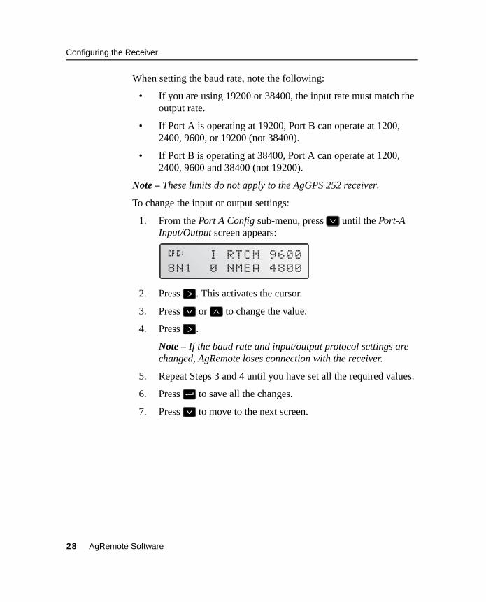
To change the input or output settings:
1. From the Port A Config sub-menu, press 2 until the Port-A Input/Output screen appears:
2. Press 3. This activates the cursor.
3. Press 2 or 1 to change the value.
4. Press 3.
Note – If the baud rate and input/output protocol settings are changed, AgRemote loses connection with the receiver.
5. Repeat Steps 3 and 4 until you have set all the required values.
6. Press 4 to save all the changes.
7. Press 2 to move to the next screen.
åæ I RTCM 96008N1 0 NMEA 4800
28 AgRemote Software

Configuring the Receiver
Selecting NMEA messages for output
When the port output setting has been changed to NMEA, use this screen to select the National Marine Electronics Association (NMEA) messages output from the current port. Only upper-case NMEA message types are output. The default messages are GGA, GSA, VTG, and RMC.
To select the NMEA messages for output:
1. From the Port A Config sub-menu screen, press 2 until the NMEA1 screen appears:
2. Press 3 to activate the cursor on the first NMEA message type.
3. Press 2 or 1 until the NMEA message type appears in uppercase.
4. Press 3 to select the next message type.
5. Repeat Steps 4 and 5 until all the message types that you want to output appear in uppercase.
6. Press 4 to save the changes.
7. Repeat this procedure in the other NMEA screens, as required.
For detailed information about the content and structure of NMEA messages, see the NMEA-0183 Messages guide on the Trimble website at www.trimble.com.
Port output rate
Use the Message Rate screen to vary the NMEA and TSIP output rate. For example, if the AgGPS Parallel Swathing Option is connected, AgGPS Lightbar data is output 5 times per second (5 Hz). At the same time, on the other port, NMEA or Trimble Standard Interface Protocol
åæ NMEA1 GGA gllgrs GSA gst gsv
AgRemote Software 29

Configuring the Receiver
(TSIP) data can be output to a computer software package, yield monitor, variable rate controller, or other equipment. That data can be output at the same rate, or at a slower rate than the lightbar data.
If you require an output rate of 2, 5, or 10 positions per second, you must have the Fast Rate Option installed in the receiver or a receiver that outputs at these rates as standard. All new AgGPS receivers come with the Fast Rate Option as standard.
Note – Select ASAP if you want the output rate to be the same as the output rate selected on the Position Rate screen under the GPS Config sub-menu.
To set the NMEA / TSIP message output rate:
1. From the Port A Config sub-menu screen, press 2 until the Message Rate screen appears:
2. Press 3 twice to set the NMEA output rate. This places the active cursor on the second digit of the NMEA line.
3. Press:
– 2 to set the output rate to ASAP
– 1 to increase the output rate by one second. Press this key as often as necessary, to a maximum of 99 seconds.
4. Press 3 twice to set the TSIP output rate. This moves the cursor to the second digit of the TSIP line. Repeat Step 3.
5. Press 4 to save the changes.
åæNMEA out 01 sTSIP out 01 s
30 AgRemote Software
Configuring the Receiver
20.1 Configuring Differential GPS
For the receiver to output GPS position coordinates of submeter accuracy, select a differential signal from one of the following sources:
• WAAS/EGNOS – free service, limited availability
The Wide Area Augmentation System (WAAS) augments GPS with additional signals for increasing the reliability, integrity, accuracy, and availability of GPS in the United States. EGNOS (European Geostationary Navigation Overlay System) is the European equivalent of WAAS.
• OmniSTAR – paid subscription, available worldwide
You can use the OmniSTAR paid service as an alternative to WAAS/EGNOS. OmniSTAR provides over-the-air DGPS activation.
To use the differential signal from the selected provider:
1. Configure the receiver.
2. Activate the receiver.
3. Enable the receiver.
For details, see the following sections.
To configure the receiver to receive signals from any provider:
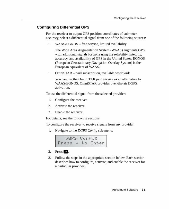
1. Navigate to the DGPS Config sub-menu:
2. Press 2.
3. Follow the steps in the appropriate section below. Each section describes how to configure, activate, and enable the receiver for a particular provider.
AgRemote Software 31

Configuring the Receiver
20.1 OmniSTAR
To use an OmniSTAR subscription service:
1. Identify the OmniSTAR coverage beam for your location.
2. Configure the DGPS source on the receiver.
3. Configure the provider name and coverage beam on the receiver.
4. Activate the subscription.
For more information about each of these steps, see the following instructions.
Note – OmniSTAR can be activated over the air only. The AgGPS 252 does not support manual activation (where OmniSTAR provides you with a usercode).
Contact the service provider for the correct satellite coverage beam for your geographic location.
In the US and Canada, contact OmniSTAR at 1- 888-883-8476 (www.omnistar.com).
You will need to provide a serial number and user code:
1. Navigate to the Serial number screen.
Record the serial number here:
2. Navigate to the Omni* screen.
Record the user code here:
To configure the DGPS Source for the subscription service:
1. In the DGPS Config sub-menu, navigate to the DGPS Source screen.
2. Press 3. This activates the cursor.
32 AgRemote Software

Configuring the Receiver
3. Press 2 until Satellite Only, OmniSTAR VBS, or OmniSTAR HP appears.
4. Press 4 to save the changes.
5. Press 5 to return to the DGPS Config sub-menu.
To configure the provider name and the correct satellite coverage beam:
1. From the DGPS Config sub-menu, press 2 until the EZ Sat screen appears.
Note – The EZ Sat screen includes the Coverage Beam field and the Geographic Location field.
2. Press 3 to activate the cursor.
3. Press 2 until the required provider (Omni*) appears.
4. To move to the next field, press 3.
5. Press 2 until the coverage beam for your location appears.
6. Press 4 to save the changes.
7. Press 5 to return to the DGPS Config sub-menu.
To activate the OmniSTAR DGPS subscription:
1. Contact OmniSTAR on 1-888-883-8476 (US or Canada). Provide OmniSTAR with:
– your billing information
– user code
– satellite beam name
OmniSTAR will activate the receiver. Activation can take5–30 minutes.
AgRemote Software 33

Configuring the Receiver
Note – To track the OmniSTAR satellite, the receiver must be outside with a clear view of the sky, turned on, and configured to receive OmniSTAR VBS or HP corrections.
2. Once the receiver is activated, the Home screen displays “D/3D”:
20.1 WAAS/EGNOS
WAAS is a free satellite-based DGPS service that is available only in North America. EGNOS is a free satellite-based DGPS service that is available only in Europe. To use the WAAS/EGNOS DGPS signal, you must first configure the receiver.
To configure the receiver to use WAAS/EGNOS DGPS:
1. From the DGPS Config sub-menu, press 2 until the DGPS Source screen appears.
2. Press 3. This activates the cursor.
3. Press 2 until WAAS/EGNOS ONLY appears:
4. Press 4 to save the changes.
To enable the WAAS/EGNOS DGPS signal:
1. Press 2 until the WAAS/EGNOS T2 Remap screen appears.
2. Press 3. This activates the cursor.
3. Press 2 until On appears:
åæ DGPS SourceWAAS/EGNOS ONLY
åæ WAAS/EGNOST2 Remap On
34 AgRemote Software

Configuring the Receiver to Operate in RTK Mode
4. To save the changes, press 4.
To enable WAAS reception in the field:
1. Take the receiver outside. Make sure that it has a clear southeast and southwest view of the sky.
2. Switch on the receiver.
WAAS activation can take two or more minutes.
3. Once activation succeeds, the Home screen displays “D/3D”:
2.1 Configuring the Receiver to Operate in RTK ModeUse AgRemote software to configure the receiver for operation in RTK mode.
Note – Your receiver must have the RTK option enabled to operate in this mode. This option is not supported by all receivers.
To configure the receiver:
1. Connect the receiver to the computer. Turn on the receiver and start the AgRemote software.
2. In AgRemote, select Configuration / DGPS Config.
3. Set the Source Select field to RTK.
4. Press 4 then 5 to complete this part of the procedure.
5. For RTK operation, connect the radio to a receiver port. Change the port input settings for that port to RtkLnk.
D/3D í07 DOP03WAAS 122 ÷ø04
AgRemote Software 35

Configuring Beacon DGPS
2.1 Configuring Beacon DGPSFollow these instructions to change an AgGPS receiver to Beacon mode.
Note – Beacon DGPS mode is not supported by all receivers.
Select the frequency of the channels to be used when receiving RTCM SC-104 broadcasts from radiobeacons:
1. Navigate to the DGPS Source screen.
2. If the screen does not display Beacon Only, press 3 to select the Data Source field. Then press 2 until Beacon Only appears.
3. Press 4 to save the changes.
4. Press 2 until the Beacon Mode screen appears:
5. Press 3 to activate the cursor. Press 2 until the required beacon mode appears. See Table 7.
Table 7 Beacon modes
Mode name Description
Auto Range mode Reads the incoming RTCM SC-104 message stream and selects the two closest radiobeacons within range of the AgGPS receiver. The closest radiobeacon is automatically assigned to Beacon DGPS Channel 0, and the second closest is assigned to Channel 1.
Auto Power mode Detects the signal strength of the two most powerful radiobeacons within range of the AgGPS receiver. The most powerful radiobeacon is automatically assigned to Beacon DGPS Channel 0, and the second is assigned to Channel 1.
36 AgRemote Software

Configuring Beacon DGPS
6. If you selected:
– Auto Range Mode or Auto Power Mode, configuration is complete. Press 5 several times to return to the Home screen.
The receiver automatically detects the two closest or two most powerful beacons.
– Manual Freq Mode, see EZ Bcn screens, page 37, or Manually selecting frequencies, page 38.
– Disabled Mode, the receiver ignores incoming RTCM SC-104 messages and operates as a GPS-only receiver.
EZ Bcn screens
The EZ Bcn 0 and EZ Bcn 1 screens use information in RTCM SC-104 broadcasts to create a list of beacon stations that are within range of the receiver.
To manually select frequencies for Beacon Channels 0 and 1:
1. Navigate to the EZ Bcn 0 screen.
2. Press 3 to select the field for Beacon Channel 0.
Disabled mode Disables DGPS and forces the AgGPS receiver to operate in GPS mode only.
Manual Freq mode Disables the automatic selection of radiobeacons so that you can manually select the frequency of radiobeacons for Channel 0 and 1.
Table 7 Beacon modes (continued)
Mode name Description
AgRemote Software 37

Configuring Beacon DGPS
3. Press 2 or 1 until the required beacon station appears:
4. Press 4 to save the changes.
5. Press 2. The EZ Bcn 1 screen appears.
6. To select the station for Beacon Channel 1, repeat Step 2 through Step 4.
Manually selecting frequencies
Note – Use this method only if you cannot find the required radiobeacon name in the list.
To manually select Beacon DGPS radiobeacon frequencies using the EZ Bcn screens:
1. Navigate to the Man Bcn Freqs screen.
2. Press 3. This activates the cursor in the Beacon Channel 0 field:
3. To enter the frequency one number at a time, press 2 or 1. Press 3 to move to the next digit.
4. Press 4 to save the changes.
5. Press 3 to select the Beacon Channel 1 field.
6. To enter the other required frequency, repeat Step 3.
7. Press 4 to save the changes.
38 AgRemote Software

Installing Passcodes
2.1 Installing PasscodesPasscodes are installed on AgGPS receivers to enable extra options or to enable a firmware upgrade.
To install a passcode using AgRemote software:
1. Start AgRemote. See page 7.
2. From the Home screen, press 2 until the Update Receiver screen appears:
3. Press 4.
4. Press 2 or 1 until the first digit of the passcode appears.
5. Press 3 to enter the digit and select the next digit.
6. Repeat Step 4 and Step 5 until all digits are entered.
7. Press 4 and then 2 to finish entering the passcode and exit the screen.
AgRemote Software 39

Navigation Maps
2.1 Navigation MapsThe menus and screens that appear in AgRemote depend on the receiver and firmware that you are using and the options you have installed.
For a diagram (navigation map) of the menus and screens that are available for each receiver, refer to the receiver documentation, or contact your local Trimble reseller.
40 AgRemote Software


![Subsampling Receivers with Applications to Software ...€¦ · Subsampling Receivers with Applications to Software Defined Radio Systems 169 The discrete time signal, x[n], can be](https://img.dokumen.tips/doc/110x75/5f2215b45c0b0c3c3b78e77e/subsampling-receivers-with-applications-to-software-subsampling-receivers-with.jpg)


