Embed Size (px)
Citation preview

AGP ProSpecification
Revision: 1.1aOriginal Date: April 1999

APG Pro -- Specification
2
Revision HistoryFollowing is a brief history of this document. The date indicates when the text was last modified, causing the revision numberto change.
Revision Date Description1.1 April, 1999 Release.
1.1a August, 1999 Reformatted by Communications Tech Pubs. Toni Haysmer & Tony HarrisonSystem Engineering.
This specification is provided “AS IS” with no warranties whatsoever including any warranty of merchantability, non-infringement, fitness for any particular purpose or any warranty otherwise arising out of any proposal, specification, or sample.No license, express or implied, by estoppel or otherwise, to any intellectual property rights is granted or intended hereby.
Intel disclaims all liability, including liability for infringement of any proprietary rights, relating to use of information in thisspecification. Intel does not warrant or represent that such use will not infringe such rights.
This document is an intermediate draft for comment only and is subject to change without notice.*Third party brands and names are the property of their respective owners.

APG Pro -- Specification
3
Table of Contents
1.0 Introduction ...................................................................................................................... 52.0 System Design Implementation....................................................................................... 6
2.1 System Design Requirements ......................................................................................... 62.1.1 High Power AGP Pro110* Card ................................................................................ 82.1.2 AGP Pro50* Card ..................................................................................................... 9
2.2 AGP Pro Motherboard Implementation.......................................................................... 102.3 AGP Card in an AGP Pro Connector............................................................................. 112.4 AGP Pro Card in an AGP Connector............................................................................. 112.5 Usage Rules of PCI Slots for Multi-Slot AGP Pro Cards................................................ 13
3.0 Electrical Specification .................................................................................................. 143.1 AGP Pro Connector Pinout............................................................................................ 143.2 AGP Pro Power............................................................................................................. 16
3.2.1 AGP Pro Power Delivery......................................................................................... 163.2.2 Power for Single-Slot AGP Pro Add-in Cards.......................................................... 163.2.3 Power For Multi-Slot AGP Pro Add-in Cards........................................................... 17
3.3 Power for AGP Pro50 Add-in Cards .............................................................................. 183.3 Power ID Pins AGP Pro Card........................................................................................ 18
4.0 Mechanical Specification............................................................................................... 194.1 Expansion Card Dimensions and Tolerances................................................................ 194.2 AGP Pro Add-in Card Connector Physical Description .................................................. 23
4.2.1 AGP Pro Add-in Card Connectors........................................................................... 234.2.2 Insertion/Extraction Force ....................................................................................... 28
4.3 AGP Pro Connector Electrical Requirements ................................................................ 284.3.1 Determination of Average Contact Resistance........................................................ 284.3.2 Mating Force........................................................................................................... 284.3.3 Unmating Force ...................................................................................................... 28
4.4 AGP Pro Brackets ......................................................................................................... 294.4.1 Three- Slot I/O Bracket Design ............................................................................... 304.4.2 Two-Slot I/O Bracket Design................................................................................... 324.4.3 AGP Pro End Retaining Bracket ............................................................................. 33
5.0 Thermal Specification .................................................................................................... 366.0 Revision History Chronology ........................................................................................ 37
APG Pro -- Specification
4
List of Figures
Figure 1: AGP Pro Connector Orientation. ................................................................................................................ 5Figure 2: AGP Pro System Design Requirements..................................................................................................... 7Figure 3: Orientation for High Power AGP Pro110 Cards. ........................................................................................ 8Figure 4: Orientation for Low Power AGP Pro50 Cards. ........................................................................................... 9Figure 5: AGP Pro Motherboard Implementation. ................................................................................................... 10Figure 6: AGP Pro Key Dimensions......................................................................................................................... 12Figure 7: AGP Pro Connector Pinout Assignments. ................................................................................................ 14Figure 8: AGP Pro Form Factor Add-In Card (3.3V)................................................................................................ 20Figure 9: AGP Pro Form Factor Add-In Card (1.5V)................................................................................................ 21Figure 10: Detail A and B: AGP Pro Card Edge Finger Layout ............................................................................... 22Figure 11: AGP Pro Connector Footprint (Based on AGP Universal Connector). .................................................. 24Figure 12: AGP Pro Connector Layout Dimension (Based on the AGP 1.5V Connector) ...................................... 25Figure 13: AGP Pro Connector Footprint (Based On APG 1.5 V Connector). ........................................................ 26Figure 14: AGP Pro Connector Layout Dimensions (Based On APG 1.5 V Connector)......................................... 27Figure 15: Isometric View of AGP Pro Brackets. ..................................................................................................... 29Figure 16: Detailed Three- Slot I/O Bracket Design. ............................................................................................... 30Figure 17: Three- Slot I/O Bracket Example (Isometric View)................................................................................. 31Figure 18: Detailed Two- Slot I/O Bracket Design. .................................................................................................. 32Figure 19: Two- Slot I/O Bracket Example (Isometric View).................................................................................... 33Figure 20: Detailed Drawing of an AGP Pro End Bracket. ...................................................................................... 34Figure 21: Full Length Card Extension Concept...................................................................................................... 35Figure 22: Thermal Envelope for AGP Pro Implementation. ................................................................................... 36
List of Tables
Table 1: AGP Pro Connector Pinout ........................................................................................................................ 15Table 2: AGP Pro Add-in Card Power Supply Limits............................................................................................... 16Table 3: Single-Slot AGP Pro Add-in Card Power................................................................................................... 16Table 4: Multi-Slot AGP Pro Add-in Card Power ..................................................................................................... 17Table 5: Add-in Card Present Settings .................................................................................................................... 18Table 6: Thermal Specification for AGP Pro System............................................................................................... 36

APG Pro -- Specification
5
1.0 Introduction
This document defines an extension to the AGP interface specification that meets the needs of advanced workstationgraphics. This new specification, AGP Pro, is primarily designed to deliver additional electrical power to the graphics add-incards. The AGP Pro definition includes an extended connector, thermal envelope, and mechanical specifications for cards,I/O brackets, and motherboard layout requirements.
AGP Pro extends the existing AGP connectors on both ends to deliver additional power on the 12 V and 3.3 V rails. Theextension is illustrated in Figure 1. AGP Pro is intended to supplement, but not replace, the existing AGP connector set.
I/O BRACKET
AGP Pro CONNECTOR
AGP CONNECTORADDEDPOWERPINS
AGP Pro END RETAINER BRACKET
MOTHERBOARD
AGP Pro GRAPHICS CARD
SOLDER SIDE
POWERPINS
ADDED
Figure 1: AGP Pro Connector Orientation.

APG Pro -- Specification
6
2.0 System Design Implementation
AGP cards come in three- (3) form factors:
• WTX• ATX• NLX
The WTX* and ATX* form factor cards have the same component area, I/O bulkhead panel, and brackets as PCI cards. TheNLX* form factors are smaller and target Basic PC systems. The AGP Pro* specification targets the WTX and ATX form factorimplementation of the AGP specification. NLX implementations for AGP cards are not defined.
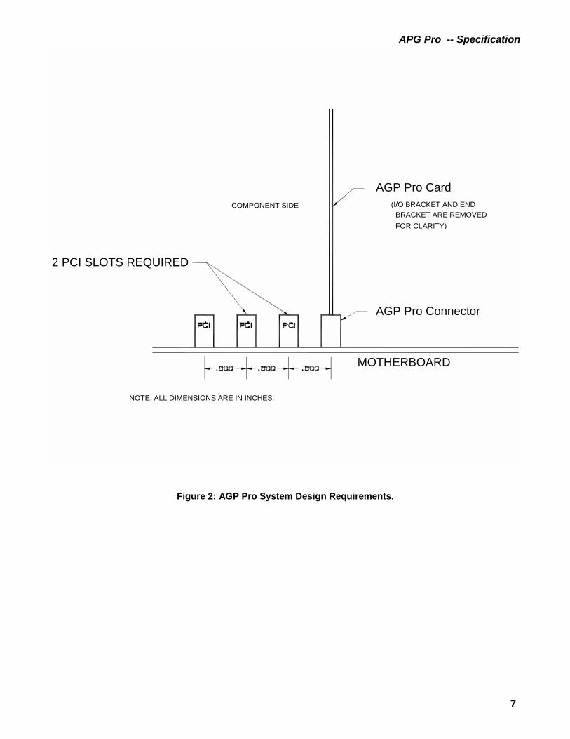
2.1 System Design Requirements
An AGP Pro compliant system must have two- (2) PCI slots adjacent to the AGP Pro connector as illustrated in Figure 2 thatfollows. The PCI slots at minimum, guarantee 33 MHz / 32 bit operation. 66 MHz or 64 bit operations are not guaranteed tobe provided on the two (2) adjacent PCI slots. Section 2.5 describes how PCI slots can be used as an option by the AGP Procard, for electrical, mechanical, or PCI functional purposes.
APG Pro -- Specification
7
AGP Pro Card
AGP Pro Connector
MOTHERBOARD
(I/O BRACKET AND ENDBRACKET ARE REMOVED FOR CLARITY)
NOTE: ALL DIMENSIONS ARE IN INCHES.
2 PCI SLOTS REQUIRED
COMPONENT SIDE
Figure 2: AGP Pro System Design Requirements.

APG Pro -- Specification
8
2.1.1 High Power AGP Pro110* Card
A High Power AGP Pro card consumes 50 to 110 Watts of power, and is called an AGP Pro110 card. This card requiressufficient space on the component side to facilitate cooling as shown in Figure 3. Two (2) adjacent PCI slots must be leftunoccupied to provide this space. The unused PCI connections provide 2.17 inches of clearance space for the card. Aspecial, three-slot wide I/O bracket installed on the AGP Pro110 High Power card reserves the use of this space. This bracketis defined in the Mechanical Specification section of this document.
Note: All retail channel High Power AGP Pro cards must use the 3-slot wide I/O bracket. AGP Pro card vendors may haveOEM specific solutions that do not require this bracket. Also, a chassis that supports an AGP Pro connector on themotherboard must be able to accept a High Power AGP Pro card equipped with up to a three wide I/O bracket.
AGP Pro Card
AGP Pro Connector
MOTHERBOARD
(I/O BRACKET AND ENDBRACKET ARE REMOVED FOR CLARITY)
NOTE: ALL DIMENSIONS ARE IN INCHES.
.600 (PCI Spec)
(PCI Spec) .570
(PCI Spec) .062
.105 (PCI Spec)
(AGP Spec) .062
.105 ( AGP Spec)
COMPONENT SIDE
RESERVED AREA
Figure 3: Orientation for High Power AGP Pro110 Cards.
APG Pro -- Specification
9
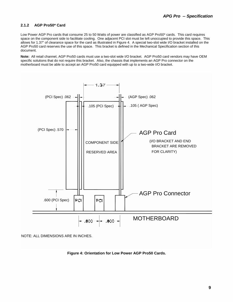
2.1.2 AGP Pro50* Card
Low Power AGP Pro cards that consume 25 to 50 Watts of power are classified as AGP Pro50* cards. This card requiresspace on the component side to facilitate cooling. One adjacent PCI slot must be left unoccupied to provide this space. Thisallows for 1.37” of clearance space for the card as illustrated in Figure 4. A special two-slot wide I/O bracket installed on theAGP Pro50 card reserves the use of this space. This bracket is defined in the Mechanical Specification section of thisdocument.
Note: All retail channel, AGP Pro50 cards must use a two-slot wide I/O bracket. AGP Pro50 card vendors may have OEMspecific solutions that do not require this bracket. Also, the chassis that implements an AGP Pro connector on themotherboard must be able to accept an AGP Pro50 card equipped with up to a two-wide I/O bracket.
AGP Pro Card
AGP Pro Connector
MOTHERBOARD
(I/O BRACKET AND ENDBRACKET ARE REMOVED FOR CLARITY)
NOTE: ALL DIMENSIONS ARE IN INCHES.
.600 (PCI Spec)
(PCI Spec) .570
(PCI Spec) .062
.105 (PCI Spec)
(AGP Spec) .062
.105 ( AGP Spec)
COMPONENT SIDE
RESERVED AREA
Figure 4: Orientation for Low Power AGP Pro50 Cards.

APG Pro -- Specification
10
2.2 AGP Pro Motherboard Implementation
An AGP Pro connector on a motherboard is illustrated in Figure 5.
RESTRICTED COMPONENTHEIGHT .200 [5.08]
RESTRICTED COMPONENT HEIGHT.200 [5.08] MAX. ON 32 BIT MOTHERBOARD FOR64 BIT CARD INTEROPERABILITY
5V PCI REFERENCE DATUM
AGP Pro REFERENCE DATUM
28 PIN BAY
REQUIRED PCI CONNECTOR
I/O BRACKET AREA
BACK OF CHASSIS
RESTRICTED COMPONENTHEIGHT .600 [15.24] MAX
1
1TO A.G.P. Pro BOARDLOCK POSITION.THIS DIMENSION IS FROM PCI BOARDLOCK LOCATION
ALL DIMENSION ARE IN INCHES AND [MM]
NOTES:
2.
20 PIN BAY
AGP Pro UNIVERSAL CONNECTOR
OFFSET DISTANCE BETWEEN BEGINNING OF DRAFTAT TOP OF SURFACE OF CONNECTOR KEY TOTHE CENTERLINE OF 2.49 DIA HOLE IN MOTHERBOARD
3.500 [88.90]
2.420 [61.47]
1.215 [30.86]
0.004 [0.10]
8.170 [207.52]
0.800 [20.32] 0.800 [20.32]
0.800 [20.32]
Figure 5: AGP Pro Motherboard Implementation.

APG Pro -- Specification
11
2.3 AGP Card in an AGP Pro Connector
AGP 3.3 V and 1.5 V connectors use the 1.78-mm wide voltage key to register the AGP add-in card. The AGP Universalconnector makes use of the 3.30-mm ‘end-housing’ in conjunction with the registration tab on the AGP add-in card to register.
The AGP Pro connector is an extension of the existing AGP connector and it accepts existing AGP cards. All versions of theAGP Pro connector make use of the 3.30-mm wide key to register existing AGP cards. Therefore, the AGP cards must have aregistration tab as defined in the AGP specification to work in the AGP Pro connector. Note that the width of the 3.3 V and 1.5V voltage key on the AGP Pro connector has been reduced to 1.68-mm from 1.78-mm, since these keys are not used toregister the AGP card. Also, to ensure correct operation with the AGP Pro connector, no vias or components should be placedon the registration tab.
2.4 AGP Pro Card in an AGP Connector
AGP Pro add-in cards will not fit into systems designed with existing AGP connectors. This is intentional, and is ensured byselecting a shorter height key for AGP Pro connectors as compared to the height of the end-housings on AGP connectors asillustrated in Figure 6. The height of the key on the side closest to the I/O bracket is 2.92-mm for AGP Pro connectors. Thecorresponding height of the ‘end-housing’ for the existing AGP connectors is 8.89-mm. This ensures that AGP Pro add-incards designed to the 2.92-mm height of the key will not fit into the existing AGP connectors.

APG Pro -- Specification
12
AGP UNIVERSAL
2. DRAWING NOT TO SCALE
AGP Pro UNIVERSAL
AGP 3.3V
AGP 1.5V
1. DIMENSIONS ARE IN MM
1.78*
1.78*
3.30* 3.30
3.30* 2.20
AGP Pro 3.3V
AGP Pro 1.5V
3.30* 2.20
3.30* 2.20
2.92
2.92
2.92
* = REGISTRATION KEYING FEATURE
1.68
1.68
I/O BRACKET SIDE
8.89
8.89
8.89
NOTES:
Figure 6: AGP Pro Key Dimensions.Figure 6 shows an AGP Pro connector based on extending the Universal AGP connector. If an AGP Pro connector is built byextending the 3.3 V or 1.5 V AGP connectors, the width of the keys must remain the same as on the AGP Pro connector. Thewidth of the keys is fixed at 2.20-mm on one end and 3.30-mm on the other end.

APG Pro -- Specification
13
2.5 Usage Rules of PCI Slots for Multi-Slot AGP Pro Cards
An AGP Pro compliant system must provide two- (2) PCI slots adjacent to the AGP Pro slot. The AGP Pro card may usethese PCI slots for mechanical support, electrical power, or PCI bus functional purposes. Multi-slot AGP Pro cards must followthe rules below in order to use the PCI slots.
If the PCI slots are used for additional power, then:
• Design a Universal PCI card edge so that it can plug into a 3 or 5 V PCI connector.
• Do not use V I/O pins on the PCI connector for power.
• Use the 3.3 or 5 V rail for power. Note that 3.3 V pins are provided on a 5 V connector also.
• Do not tie M66EN (pin 49-side B) to GND on the card because this slows a 66 MHz bus to 33 MHz operation.
If the multi-slot AGP Pro card is using the PCI slots for PCI Bus functionality, then:
• Design the card to work with 33 MHz/32 bit PCI bus as only this is guaranteed to be available. 66 MHz or 64 bitPCI operation is not guaranteed to be provided on the adjacent PCI slots.
• Design the I/O buffers on the PCI component to operate at 3.3 V with 5 V tolerance.
While it is recommended that the system be designed to deliver 3.3 V to both the PCI and AGP Pro slots from a common 3.3VVcc plane, it is not always possible given the limitations of existing power supplies. Some systems may need to deliver currentfrom both the main power supply and a local 3.3 V DC-DC converter. In this case, the multi-slot AGP Pro solution needs tomake provisions so the two sources of 3.3 V power are not interconnected. Therefore, when designing multi-slot 3.3 V cards,any connector or cable tying the AGP Pro and multiple PCI cards together, cannot bridge the 3.3 V AGP Pro to the 3.3 V PCIslot 1 and PCI slot 2.

APG Pro -- Specification
14
3.0 Electrical Specification
3.1 AGP Pro Connector Pinout
The AGP Pro connector is designed as an extension to the existing AGP connectors. The AGP connectors are extended onboth ends to build the AGP Pro connector. It is a monolithic connector. Any of the specified AGP connectors can be extendedto build the AGP Pro connector. This section illustrates the use of the Universal AGP connector to build the AGP Proconnector. The Universal connector can be replaced with 3.3 V or 1.5 V AGP connectors to build the AGP Pro connector.
Figure 7 shows the AGP Pro connector layout based on extending the Universal AGP connector.Table 1 lists the pinout for the extended part of the AGP Pro connector.
TOP
VIEW
RES
ERVE
D
I/O
PRSN
T2#
PR
SN
T1#
2 PI
NS
2 P
INS
20 P
INS
10 P
INS
6 P
INS
===== 3.3
AGP
Pro
PIN
OU
T
TOTA
L
3.3
3.3
GN
D GN
D
P RSN
T#
GN
D V
CC
3.3
3.3
RES
3.3
3.3
RES
3.3
TOTA
L
RES
RES
RES
ERVE
D
VC
C12
V
A GP
Pro
PIN
OU
T
4 P
INS
12 P
INS
12 P
INS
28 P
INS
12 GN
D
12 GN
D
12 GN
D
RES
GN
D
RES
12
12 GN
D
GN
DG
ND
1212
GN
D
====
GN
D
GN
D
GN
D
GN
D
GN
D1212
1212
12G
ND 3.
3GN
D GN
D
GN
D
3.3
3.3
NO
TE: P
INS
A 1-A
66, B
1-B6
6 AR
E TH
E AG
P U
NIV
ERSA
L C
ON
NEC
TOR
D1
D9
D2
D10C
9 C1
C2
C10
B2 B1A1 A2
NO
TES:
A66
A65
B65
B66
F2F13
F1F14
E1 E13
E14
E2
DR
AWIN
G N
OT
TO S
CAL
E
BRAC
KET
END
Figure 7: AGP Pro Connector Pinout Assignments.

APG Pro -- Specification
15
Table 1: AGP Pro Connector Pinout
AGP Pro ExtendedConnector
Pin # D C
1 VCC3.3 VCC3.3
2 VCC3.3 Ground
3 VCC3.3 VCC3.3
4 VCC3.3 Ground
5 VCC3.3 Ground
6 VCC3.3 Ground
7 VCC3.3 Ground
8 VCC3.3 Ground
9 PRSNT2# Reserved
10 PRSNT1# Reserved
F E
1 Reserved Reserved
2 Reserved Reserved
3 Ground VCC12
4 Ground VCC12
5 Ground VCC12
6 Ground VCC12
7 Ground VCC12
8 Ground VCC12
9 Ground VCC12
10 Ground VCC12
11 Ground VCC12
12 Ground VCC12
13 Ground VCC12
14 Ground VCC12
Note: Since Pins A1–A66 and B1–B66 are the same as for the AGP connector they are not listed in this table.

APG Pro -- Specification
16
3.2 AGP Pro Power
3.2.1 AGP Pro Power Delivery
Table 2 lists the voltage ranges for the 3.3 V and 12 V power supplies and the maximum current that can be supplied via theextended part of the AGP Pro connector. This information is provided for the designer of the DC/DC converters on the AGPPro card.
Table 2: AGP Pro Add-in Card Power Supply Limits
Symbol Parameter Condition Min Max Units
VCC3.3 3.3 V power supply Imax = 7.6 A 3.15 3.45 Volts
VCC12 12 V power supply Imax = 9.2 A 10.2 12.6 Volts
The motherboard must connect all power supply pins on the connector to guarantee proper current delivery and to provideproper AC signal return paths. The AGP Pro add-in card must attach all connector power pins to appropriate power planes onthe card for good power delivery and signal returns. AGP Pro cards must use all ground pins. Appropriate capacitivedecoupling (high frequency and bulk) must be provided on all voltage rails used on the add-in card and on the motherboard.
To prevent interactions with other items powered by the VCC rails, the DC-DC converters on the AGP Pro card cannot inducetransients on either the VCC3.3 or VCC12 input lines greater that 0.1A/µs under any loading conditions. These restrictionsinclude going from low power mode (i.e., sleep mode), to full power mode.
3.2.2 Power for Single-Slot AGP Pro Add-in Cards
An AGP Pro card may draw power either from the existing part of the AGP Pro connector, the extended part, or a combinationof the two. In all cases, the maximum power that may be drawn by an AGP Pro card is limited to 110 W. Power on theexisting part of the connector is delivered on 5.0 V and 3.3 V rails. Power on the extensions is delivered on the 12 V and 3.3 Vrails.
Table 3 lists some of the possible combinations allowed for an AGP Pro add-in card designed for the AGP Pro connector.This add-in card draws no power from the two- (2) adjacent PCI slots. Other combinations are possible within the guidelines.
Table 3: Single-Slot AGP Pro Add-in Card Power
AGP Pro Total Power Comments
Supported Combinations
AGPconnector
(Max Power)
Additional power fromextensions (Max
Power)
0 W 110 W–12 V 110 W
25 W 85 W–12V 110 W
25 W 25 W–3.3 V
60 W–12 V
110 W
Unsupported Combinations
25 W 110 W–12 V 135 W Exceeds total power limit of 110 W
25 W 25 W–3.3 V
110 W–12 V
160 W Exceeds total power limit of 110 W

APG Pro -- Specification
17
3.2.3 Power For Multi-Slot AGP Pro Add-in Cards
Multi-Slot AGP Pro cards draw power from the adjacent PCI slots in addition to the AGP Pro slot. The maximum powerbudget for AGP Pro, plus two- (2) adjacent PCI slots is limited to 110 W. Table 4 that follows, lists some possiblecombinations allowed for an AGP Pro add-in card designed for the multiple slots. Other combinations are possible but mustbe kept below the 110 W maximum range.
Table 4: Multi-Slot AGP Pro Add-in Card Power
AGP PRO CONNECTOR PCI
Slot 1(Max
power)
PCI
Slot 2(Max
Power)
TotalPower
Comments
Supported Combinations
AGPconnector
(MaxPower)
Additional powerfrom extensions
(Max Power)
0 W 110 W–12 V 0 W 0 W 110 W
25 W 85 W–12 V 0 W 0 W 110 W
25 W 25 W–3.3V10 W–12 V
25 W 25 W 110 W
25 W 25 W–3.3 V35 W–12 V
25 W 0 W 110 W
Unsupported Combinations
25 W 25 W–3.3 V20 W–12 V
25 W 25 W 120 W Exceeds total power limitof 110 W
25 W 25 W–3.3 V110 W–12V
25 W 25 W 210 W Exceeds total power limitof 110 W

APG Pro -- Specification
18
3.3 Power for AGP Pro50 Add-in Cards
AGP Pro50 Cards can draw up to 50W of power from either 3.3 V or 12 V or some combination of the two voltage rails. Multi-slot solutions are allowed to draw a total of 50W from the AGP Pro slot and the adjacent PCI slot.
AGP Pro50 systems use the existing AGP Pro connector. The only difference is that 50W of power are provided on the 12 V(4.17A) extension instead of 110W. The power requirement for the 3.3 V extension is still 25W (7.6A) and the powerrequirements for the main part of the AGP connector is also 25W. The systems power supply should allocate 50W (4.17A) at+12V and 50W (15.2A) at 3.3V for a fully configured system.
3.3 Power ID Pins AGP Pro Card
Two- (2) pins are defined specifically on the AGP Pro connector, PRSNT1# and PRSNT2#. They are used for two- (2)purposes:
• Indicating that an AGP Pro cardboard is physically present in the slot.
• Providing information on the maximum power requirements of the card plugged into the AGP Pro connector.Table 5 defines the required settings for the PRSNT# pins for the AGP Pro add-in card.
AGP Pro50 systems can also use the Power ID pins (PRSNT1# and PRSNT2#) to detect APG Pro cards that consume morethat 50W of power. Based on this, the system can take appropriate action to prevent damage and report problems.
Note: No mechanical means has been provided to prevent the insertion of an AGP Pro card into a system that supports onlyAGP Pro50 cards.
Table 5: Add-in Card Present Settings
PRSNT1# PRSNT2# AGP Pro Slot Configuration
Open Open No expansion board present
Ground Open Expansion board present, 50 W Max. power
Ground Ground Expansion board present, 110 W Max. power
Open Ground Reserved
In providing the power level indication, the pin strapping must indicate the total maximum power consumption of a fullyconfigured AGP Pro card. The maximum power consumption may be more than that consumed in the card’s shippingconfiguration. (E.g., sockets for memory expansion, etc.)
The system developer may use these signals for system configuration, diagnostics, or power allocation. If the signals areused by the motherboard, the system developer must provide pull-up resistors for both these signals. The systems developerdetermines the value of the resistor and the pull-up voltage based on the associated circuitry.
Note: On the AGP Pro add-in cards, these signals are either tied-to-ground, or left unconnected based on the information inTable 5.

APG Pro -- Specification
19
4.0 Mechanical Specification
4.1 Expansion Card Dimensions and Tolerances
Figure 8 shows an AGP Pro form factor add-in card based on 3.3 V card edge. AGP Pro add-in cards designed for a 1.5 Vcard-edge must change the location of the 3.3 V key to the 1.5 V key location, as shown in Figure 9. Refer to the AGPspecification for the location and dimension of the 1.5 V key.

APG Pro -- Specification
20
Figure 8: AGP Pro Form Factor Add-In Card (3.3V)

APG Pro -- Specification
21
Figure 9: AGP Pro Form Factor Add-In Card (1.5V)

APG Pro -- Specification
22
Figure 10: Detail A and B: AGP Pro Card Edge Finger Layout

APG Pro -- Specification
23
4.2 AGP Pro Add-in Card Connector Physical Description
Any of the specified AGP connectors can be extended to build the AGP Pro connector. This section illustrates the use of theUniversal AGP connector to build the Universal version of the AGP Pro connector. This section also illustrates the use of 1.5V AGP connectors used to build the 1.5 V version of the AGP Pro connector. The 3.3 V version of the AGP Pro connector isnot illustrated. The 3.3 V AGP Pro connector can easily be designed based on the data provided.
Contact specifications for the AGP connector family, are listed in the AGP Specification. Only the specifications of the AGPPro connector are listed in this section.
4.2.1 AGP Pro Add-in Card Connectors
a) Universal AGP Pro Connector
Refer to the following Figure 11 for the Universal AGP Pro connector dimensions. Refer to Figure 12 for the Universal AGPPro connector layout dimensions.

APG Pro -- Specification
24
Figure 11: AGP Pro Connector Footprint (Based on AGP Universal Connector)

APG Pro -- Specification
25
Figure 12: AGP Pro Connector Layout Dimension (Based on the AGP 1.5V Connector)
APG Pro -- Specification
26
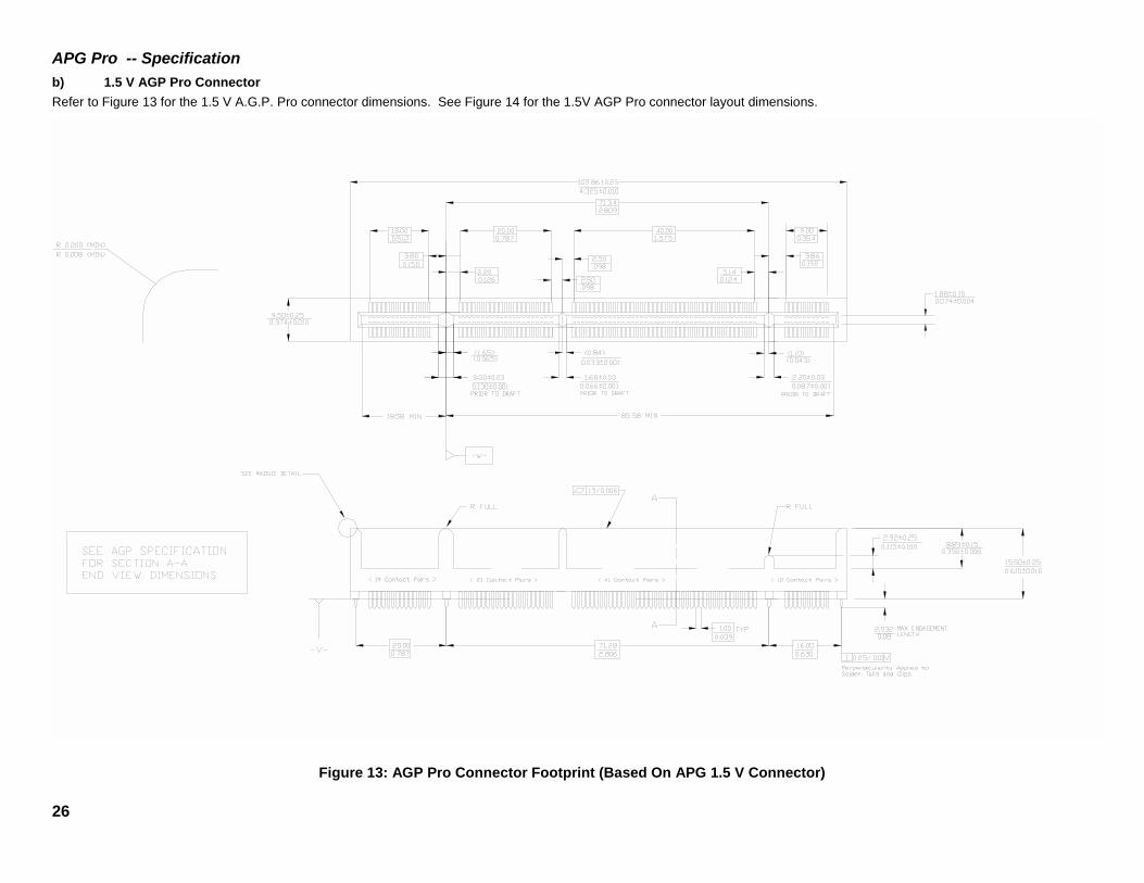
b) 1.5 V AGP Pro ConnectorRefer to Figure 13 for the 1.5 V A.G.P. Pro connector dimensions. See Figure 14 for the 1.5V AGP Pro connector layout dimensions.
Figure 13: AGP Pro Connector Footprint (Based On APG 1.5 V Connector)

APG Pro -- Specification
27
Figure 14: AGP Pro Connector Layout Dimensions (Based On AGP 1.5 V Connector).

APG Pro -- Specification
28
4.2.2 Insertion/Extraction Force
• Insertion force of PCB into AGP Pro connector: 18.6 lbf (max)• Extraction force of PCB from AGP connector: 11.2 lbf (max)• AGP Pro connector shall withstand a minimum of 50 insertion/extraction cycles with an AGP Pro add-in card.
4.3 AGP Pro Connector Electrical Requirements
All AGP Pro connector electrical requirements are the same as the AGP connector specification except for the changes listedin Sections 4.3.1, 4.3.2, and 4.3.3.
4.3.1 Determination of Average Contact Resistance
• Measure Total Contact Resistance RAB for each of the 180 AGP Pro contacts.• Measure Bulk Contact Resistance RAC for each of the 90 AGP Pro lower contacts.• Determine Contact Resistance for each of the 180 AGP Pro contacts using either RCB = RAB for upper contacts
or RCB = RAB - RAC for lower contacts.
4.3.2 Mating Force
The total mating force for the AGP Pro Connector is <18.7 lb. Refer to the AGP specification for specific testing requirements.
4.3.3 Unmating Force
The total extraction force for the AGP Pro connector is <11.3 lb. See the AGP specification for specific testing requirements.

APG Pro -- Specification
29
4.4 AGP Pro Brackets
Specially designed I/O brackets are necessary for proper implementation of the AGP Pro. Figure 15 shows a High PowerAGP Pro add-in card with three- slot wide I/O bracket and an end retainer bracket.
END BRACKET
THREE SLOT I/O BRACKET
COMPONENT SIDEAGP Pro CARD
Figure 15: Isometric View of AGP Pro Brackets.

APG Pro -- Specification
30
4.4.1 Three- Slot I/O Bracket Design
Figure 16 shows a detailed drawing of a three- slot I/O Bracket design. Figure 17 shows an isometric view of the three- slot I/O bracket with holes in the I/O connector, ventingwindow. The size and number of holes must follow proper EMI and thermal design guidelines.
Figure 16: Detailed Three- Slot I/O Bracket Design.

APG Pro -- Specification
31
Figure 17: Three- Slot I/O Bracket Example (Isometric View).

APG Pro -- Specification
32
4.4.2 Two-Slot I/O Bracket Design
Figure 18 shows a detailed drawing of a two- slot I/O Bracket design. Figure 19 shows an isometric view of the two- slot I/O bracket with holes in the I/O connectors, ventingwindow. The size and number of holes must follow proper EMI and thermal design guidelines.
Figure 18: Detailed Two- Slot I/O Bracket Design.

APG Pro -- Specification
33
Figure 19: Two- Slot I/O Bracket Example (Isometric View).
4.4.3 AGP Pro End Retaining Bracket
A full length AGP Pro card must be equipped with an end, retaining bracket as shown in Figure 20, and an isometric view ofthe AGP Pro End Retaining Bracket design. This end bracket provides holes for two- (2) additional hold down locations.OEM’s may use this feature on the end brackets to hold down AGP Pro add-in cards.

APG Pro -- Specification
34
Figure 20: Detailed Drawing of the AGP Pro End Bracket.

APG Pro -- Specification
35
For AGP Pro cards that are not full-length, it is strongly recommended that the card be extended to utilize the AGPPro end, retaining bracket. This provides a retention mechanism for the card. The card can be extended using theconcept shown in Figure 21. Other mechanical means can be used to extend the card.
I/O BRACKET
AGP Pro CONNECTOR
AGP Pro END RETAINER BRACKET
MOTHERBOARD
AGP Pro GRAPHICS CARD
SOLDER SIDE
FULL LENGTH CARD EXTENSION BRACKET
Figure 21: Full Length Card Extension Concept.
The retention mechanism for AGP cards using the notch in the registration tab will not work when AGP cards are used in anAGP Pro system. In order to use AGP cards in an AGP Pro system it is strongly recommended that the cards be extended toutilize AGP Pro end retaining bracket. This provides a retention mechanism for the AGP card. These cards can be extendedusing the concept shown in Figure 21.
In fact the full-length AGP cards can be equipped with the AGP Pro end, retaining bracket to operate in both the AGP andAGP Pro systems.

APG Pro -- Specification
36
5.0 Thermal Specification
Figure 22 represents a thermal envelope for AGP Pro implementations. System vendors will need to provide a minimum of200 LFM of non-obstructed airflow at the inlet of this envelope for AGP Pro110 cards. The maximum inlet temperature is45 °C.
AGP Pro UNIVERSAL CONNECTOR
PCI SLOT
PCI SLOT
DIRECTIONAIR FLOW
THREE SLOT I/O
200 LFM min.
45 C / 5000 FT.
BRACKET
AIR FLOW CROSS SECTIONREFERENCE POINT
NOTE: ALL DIMENSIONS SHOWN IN INCHES 2.1 INCHES IN Z AXISFROM MOTHERBOARD
INTERNAL SYSTEM AMBIENT
Figure 22: Thermal Envelope for AGP Pro Implementation.The AGP Pro add-in card vendor should do thermal modeling based on the requirements listed in Table 6. If the AGP Procard has additional cooling requirements, it must provide its own cooling solutions within the AGP Pro envelop. I/O brackets,(with holes), may be used by graphics vendors to provide venting. These brackets are specified in Section 4.
Table 6: Thermal Specification for AGP Pro System
Symbol Parameter Min Max Units Notes
Ta Ambient Temperature 45 C° 1
Af Air flow 200 LFM 1, 2
Notes:1. Measured at the reference point in the cross section of inlet.2. LFM is linear feet per minute.

APG Pro -- Specification
37
6.0 Revision History Chronology
Revision History:
Revision 1.0 August 1998 Released to www.agpforum.org web site
Revision 1.1 April 1999 Section 2 Added form factor informationSection 2.1.2 Clarification on AGP Pro50Section 2.2 Change Figure 2-4 AGP Pro Planarimplementation, to reflect a change in dimension fromboard lock to center of key are not collinear. Added notefor clarity.Section 2.5 Clarification on the 3.3V separation betweenAGP pro and PCI slots.Section 3.2.1 Change text to show 3.3V power isdelivered through the extended part of the AGP Proconnector. Update Table 3.2 to reflect new 12Vtolerances.Section 3.3 Added section for AGP Pro50 cardsSection 3.4 Added AGP Pro50 ReferenceSection 4.1 Changed dimensions for 3.3V card edge.Added 1.5V card edge Figure 4-1B. Changed Figure 4-1Bto 4-1C.Section 4.2.1.2 Change Figure 4-5 to reflect proper 1.5Vorientation on AGP Pro 1.5V connector layout dimensions.Section 4.4.1 and 4.4.2 Change Three and Two Slot I/OBrackets to reflect changes in dimensions.Section 4.4.3 Added new text regarding retention of AGPcard used in an AGP Pro system.