Embed Size (px)
Citation preview

GAIL (INDIA) LIMITED (A.GOVT OF INDIA UNDERTAKING)
CHAINSA – JHAJJAR PIPELINE PROJECT
BID DOCUMENT FOR
POWER SOURCE
VOL II OF II – TECHNICAL
(BID DOCUMENT NO 11/0230/JPK/GAIL/12-R0)
LIMITED INTERNATIONAL COMPETITIVE BIDDING
ISSUED BY

GAIL (India) Limited CHAINSA – JHAJJAR-BAMNOULI
PIPELINE PROJECT
CLIENT JOB NO. 0230 MATERIAL REQUISITION FOR
SOLAR ELECTRIC POWER SOURCE TOTAL SHEETS 16
DOCUMENT NO 11 0230 01 10 06 001
C 18/11/08 ISSUED FOR TENDER SB SP PKS
B 26/08/08 ISSUED FOR BID SB SP PKS
A 12/08/08 ISSUED FOR REVIEW SB SP PKS
REV DATE DESCRIPTION PREP CHK APPR
Page 1 of 73

Document No. Rev
11-0230-01-10-06-001 C
MATERIAL REQUISITION
FOR SOLAR ELECTRIC POWER SOURCE SHEET 2 of 17
TABLE OF CONTENTS 1.0 LIST OF ATTACHMENTS ………………………………………………………….3 2.0 SCOPE OF SUPPLY ………………………………………………………………….4 3.0 GENERAL NOTES ………………………………………………………………….8 4.0 REMARKS …………………………………………………………………………….8 5.0 SPECIAL INSTRUCTION TO BIDDER …………………………………………....9 6.0 CHECK LIST………………….………………………………………………………10 7.0 COMPLIANCE STATEMENT………………………………………………………11 8.0 FORM-A ………………………………………………………………………………12 9.0 FORM-B ………………………………………………………………………………13 10.0 FORM-C ………………………………………………………………………………14 11.0 VENDOR DRAWING DOCUMENT SUBMISSION SCHEDULE………….……15 12.0 LIST OF VENDORS ………………..………………………………………….......16
Page 2 of 73
Document No. Rev
11-0230-01-10-06-001 C
MATERIAL REQUISITION
FOR SOLAR ELECTRIC POWER SOURCE SHEET 3 of 17
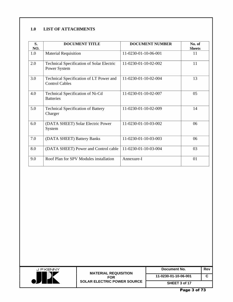
1.0 LIST OF ATTACHMENTS
S. NO.
DOCUMENT TITLE DOCUMENT NUMBER No. of Sheets
1.0 Material Requisition 11-0230-01-10-06-001
11
2.0 Technical Specification of Solar Electric Power System
11-0230-01-10-02-002 11
3.0 Technical Specification of LT Power and Control Cables
11-0230-01-10-02-004 13
4.0 Technical Specification of Ni-Cd Batteries
11-0230-01-10-02-007 05
5.0 Technical Specification of Battery Charger
11-0230-01-10-02-009 14
6.0 (DATA SHEET) Solar Electric Power System
11-0230-01-10-03-002 06
7.0 (DATA SHEET) Battery Banks
11-0230-01-10-03-003 06
8.0 (DATA SHEET) Power and Control cable
11-0230-01-10-03-004 03
9.0 Roof Plan for SPV Modules installation
Annexure-I 01
Page 3 of 73

Document No. Rev
11-0230-01-10-06-001 C
MATERIAL REQUISITION
FOR SOLAR ELECTRIC POWER SOURCE SHEET 4 of 17
2.0 SCOPE OF SUPPLY 2.1 GENERAL
This specification covers the scope of supply of the Solar Electric Power System to be installed in the Chainsa-Jhajjar-Bamnouli Natural Gas Pipeline Project and spurline to Bamnouli PPCL.
The scope of supply covers the design, manufacture, inspection, testing, supply & supervision
of installation, testing and commissioning, transportation, documentation of this item in accordance with the requirements of this requisition.
2.2 Material Delivery Requirements
The finished materials are to be delivered by the Supplier at various stations across the pipeline route. The Supplier shall be responsible for all handling, transportation and storage between his production plant and the delivery points in accordance with this specification.
2.3 DESCRIPTION OF EQUIPMENT AND/ OR SERVICES 2.3.1 LOCATION: DESPATCH STATION AT CHAINSA Item No. Qty. Description
1.0 1 lot Photo voltaic solar panels with mounting accessories, Solar Power Controller Panel for daily load demand of 1200W with system voltage: 24V DC (floating)
2.0 1 lot Ni-Cd Battery set(72 hrs. back up) with Battery float Charger (battery charger shall be hybrid type i.e., battery shall be capable
of charging from Solar system as well as from SEB power), stand and its accessories.
3.0 1 lot Junction boxes and Nickel/Chromium plated double compression
type brass cable glands and tinned copper lugs, as required. 4.0 1 lot Flame retardant low smoke (FRLS) type interconnecting cables
between solar panels and main junction boxes/solar controller panel, between battery, solar controller panel & battery charger as required.
5.0 1 No. Boost charger for battery, transportable for charging the battery of
other station
Page 4 of 73

Document No. Rev
11-0230-01-10-06-001 C
MATERIAL REQUISITION
FOR SOLAR ELECTRIC POWER SOURCE SHEET 5 of 17
6.0 L.S. Supply, Installation, Testing and Commissioning at site.
7.0a 1 lot 2 kVA(load), redundant type battery charger suitable for input power supply voltage of 230V, +/-10%, 50Hz +/-5%, output 24V +/-1%, DC, DCDB(1 no. 100A 2 pole DC MCCB as incomer and min. 6 nos. 10A/20A 2 pole DC MCCB outgoings) and 12 hrs. Battery back-up (Ni-Cd)
7.0b 1 lot All interconnecting cables among charger, battery, DCDB etc. 2.3.2 LOCATION: SV-2 STATION Item No. Qty. Description
1.0 1 lot Photo voltaic solar panels with mounting accessories, Solar Power Controller Panel for daily load demand of approx. 800W with system voltage: 24V DC (floating)
2.0 1 lot Ni-Cd Battery set(72 hrs. back up) with Battery float Charger (battery charger shall be hybrid type i.e., battery shall be capable
of charging from Solar system as well as from SEB power), stand and its accessories.
3.0 1 lot Junction boxes and Nickel/Chromium plated double compression type brass cable glands and tinned copper lugs, as required.
4.0 1 lot Flame retardant low smoke (FRLS) type interconnecting cables
between solar panels and main junction boxes/solar controller panel, between battery, solar controller panel & battery charger as required.
5.0 L.S. Supply, Installation, Testing and Commissioning at site.
2.3.3 LOCATION: SV-3 STATION Item No. Qty. Description
1.0 1 lot Photo voltaic solar panels with mounting accessories, Solar Power Controller Panel for daily load demand of approx. 1200W with system voltage: 24V DC (floating)
Page 5 of 73
Document No. Rev
11-0230-01-10-06-001 C
MATERIAL REQUISITION
FOR SOLAR ELECTRIC POWER SOURCE SHEET 6 of 17
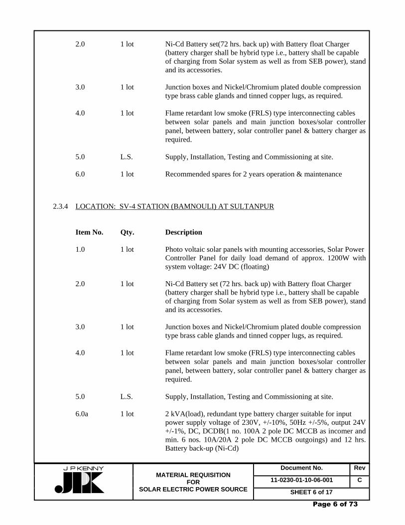
2.0 1 lot Ni-Cd Battery set(72 hrs. back up) with Battery float Charger (battery charger shall be hybrid type i.e., battery shall be capable
of charging from Solar system as well as from SEB power), stand and its accessories.
3.0 1 lot Junction boxes and Nickel/Chromium plated double compression
type brass cable glands and tinned copper lugs, as required. 4.0 1 lot Flame retardant low smoke (FRLS) type interconnecting cables
between solar panels and main junction boxes/solar controller panel, between battery, solar controller panel & battery charger as required.
5.0 L.S. Supply, Installation, Testing and Commissioning at site.
6.0 1 lot Recommended spares for 2 years operation & maintenance
2.3.4 LOCATION: SV-4 STATION (BAMNOULI) AT SULTANPUR Item No. Qty. Description
1.0 1 lot Photo voltaic solar panels with mounting accessories, Solar Power Controller Panel for daily load demand of approx. 1200W with system voltage: 24V DC (floating)
2.0 1 lot Ni-Cd Battery set (72 hrs. back up) with Battery float Charger (battery charger shall be hybrid type i.e., battery shall be capable
of charging from Solar system as well as from SEB power), stand and its accessories.
3.0 1 lot Junction boxes and Nickel/Chromium plated double compression
type brass cable glands and tinned copper lugs, as required. 4.0 1 lot Flame retardant low smoke (FRLS) type interconnecting cables
between solar panels and main junction boxes/solar controller panel, between battery, solar controller panel & battery charger as required.
5.0 L.S. Supply, Installation, Testing and Commissioning at site.
6.0a 1 lot 2 kVA(load), redundant type battery charger suitable for input
power supply voltage of 230V, +/-10%, 50Hz +/-5%, output 24V +/-1%, DC, DCDB(1 no. 100A 2 pole DC MCCB as incomer and min. 6 nos. 10A/20A 2 pole DC MCCB outgoings) and 12 hrs. Battery back-up (Ni-Cd)
Page 6 of 73

Document No. Rev
11-0230-01-10-06-001 C
MATERIAL REQUISITION
FOR SOLAR ELECTRIC POWER SOURCE SHEET 7 of 17
6.0b 1 lot All interconnecting cables among charger, battery, DCDB etc. 2.3.5 LOCATION: RECEIVING STATION AT JHAJJAR Item No. Qty. Description
1.0 1 lot Photo voltaic solar panels with mounting accessories, Solar Power Controller Panel for daily load demand of approx. 1200W with system voltage: 24V DC (floating)
2.0 1 lot Ni-Cd Battery set(72 hrs. back up) with Battery float Charger (battery charger shall be hybrid type i.e., battery shall be capable
of charging from Solar system as well as from SEB power), stand and its accessories.
3.0 1 lot Junction boxes and Nickel/Chromium plated double compression
type brass cable glands and tinned copper lugs, as required. 4.0 1 lot Flame retardant low smoke (FRLS) type interconnecting cables
between solar panels and main junction boxes/solar controller panel, between battery, solar controller panel & battery charger as required.
5.0 L.S. Supply, Installation, Testing and Commissioning at site.
Note that Solar power source should be capable to deliver station critical load in addition to the full charging current of the battery during sunny period.
3.0 GENERAL NOTES
3.1 Solar electric power source/Battery charger shall be as per technical specification.
3.2 Bidder shall quote separately for spares for two years normal operation of Solar electric power source/ Battery charger as per price schedule. List of spares quoted shall be furnished as per Form-C.
3.3 Bidder to include the start up and commissioning spares for Solar electric power source/Battery Charger in the quoted price. However, list of spares (start up and commissioning) shall be made available without cost as per Form-B.
3.4 Bidder must submit duly filled up and signed data sheets, compliance statement, Check List and forms (Form-A, Form-B, & Form-C,) along with his offer.
Page 7 of 73

Document No. Rev
11-0230-01-10-06-001 C
MATERIAL REQUISITION
FOR SOLAR ELECTRIC POWER SOURCE SHEET 8 of 17
In the absence of this information, Company reserves the right to reject bidder’s offer without any reference to Bidder in this regard.
4.0 REMARKS 4.1 Supplier’s Compliance Supplier shall submit his bid in full compliance with the requirements of this Material Requisition (MR) and attachments. Bidder shall include the following statement in his bid: We certify that our bid is fully complying with your enquiry dated …….. and referenced ……,
Compliance with this Material Requisition in any instance shall not relieve the Vendor of his responsibility to meet the specified performance.
4.2 Compliance with Specification The supplier shall be completely responsible for the design, manufacture, inspection, testing, supply & supervision of installation, testing and commissioning, transportation & storage of above material at various stations across the pipeline route in accordance with the MR and all attachments thereto.
4.3 Supplier’s Scope Supplier’s scope of work includes the equipment with all internals & accessories shown on the
specification, data sheet and all unmentioned parts necessary for the completeness and satisfactory operation & testing of the complete system.
4.4 Testing & Inspection
All tests shall be carried out as per relevant standards at Vendor's works. The company reserves the right to have a representative to witness the final testing and inspection. Prior intimation of at least 20 days shall be given to enable the Company depute its representative to witness the tests.
4.5 Certification
Supplier shall have IEC/UL/CE certification for solar photovoltaic module/system & ISO certification for manufacturing of solar photovoltaic module/system/ Renewable Energy System. .
5.0 SPECIAL INSTRUCTIONS TO BIDDERS 5.1 Bidder to note that no correspondence shall be entered into or entertained after the bid
submission. 5.2 Bidder shall furnish quotation only in case he can supply material strictly as per this Material Requisition and specification/data sheet forming part of Material Requisition.
Page 8 of 73
Document No. Rev
11-0230-01-10-06-001 C
MATERIAL REQUISITION
FOR SOLAR ELECTRIC POWER SOURCE SHEET 9 of 17
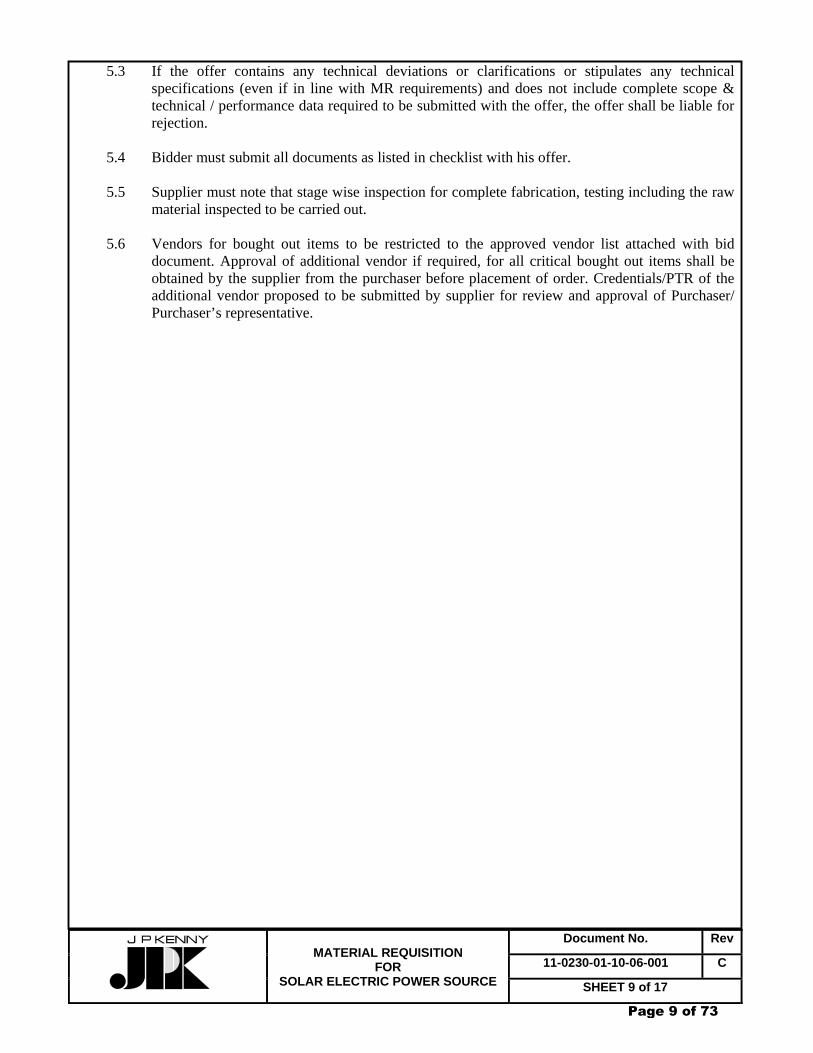
5.3 If the offer contains any technical deviations or clarifications or stipulates any technical specifications (even if in line with MR requirements) and does not include complete scope & technical / performance data required to be submitted with the offer, the offer shall be liable for rejection.
5.4 Bidder must submit all documents as listed in checklist with his offer. 5.5 Supplier must note that stage wise inspection for complete fabrication, testing including the raw
material inspected to be carried out. 5.6 Vendors for bought out items to be restricted to the approved vendor list attached with bid
document. Approval of additional vendor if required, for all critical bought out items shall be obtained by the supplier from the purchaser before placement of order. Credentials/PTR of the additional vendor proposed to be submitted by supplier for review and approval of Purchaser/ Purchaser’s representative.
Page 9 of 73

11-0230-01-10-06-001 Rev. C SHEET 10 of 17
REQUISITION FOR SOLAR ELECTRIC POWER SOURCE
PROJECT CHAINSA-JHAJJAR-BAMNOULI PIPELINE PROJECT
CHECKLIST – TECHNICAL
Bidder confirms following, as a minimum, has been enclosed in the offer.
S.NO. Requirements Compiled by Bidder
1 Reference List of previous supply of Solar Electric Power Source Yes/No
2 Filled – up Data Sheets, duly signed and stamped by bidder enclosed. Yes/No
3 List of recommended commissioning spares and accessories for Solar Electric Power Source enclosed. Yes/No
4 List of recommended spares and accessories for two year normal operation for Solar Electric Power Source. Yes/No
5 Compliance statement duly filled and stamped enclosed. Yes/No
6 GA & assembly drawings, cross section drawings including part list & material list enclosed. Yes/No
7 Other technical details & vendor’s product catalogues enclosed. Yes/No
Page 10 of 73

11-0230-01-10-06-001 Rev. C SHEET 11 of 17
REQUISITION FOR SOLAR ELECTRIC POWER SOURCE
PROJECT CHAINSA-JHAJJAR-BAMNOULI PIPELINE PROJECT
COMPLIANCE STATEMENT
S.No. Requirement Bidder’s Confirmation
1 Bidder confirms that all materials proposed by the bidder are same/ superior to those specified in specification/ data sheets enclosed.
2
Bidder confirms that the offer is in total compliance with the Technical requirements of the Material Requisition. Bidder confirms that deviation expressed or implied any where else in the offer shall not be considered valid.
3 Bidder confirms that all spares and accessories required for two years of normal operation have been quoted separately as per price Performa enclosed with Bid Document.
4
Bidder confirms that prices for start-up/commissioning spares and accessories have been included in the quoted items
5
Bidder confirms that in the event of securing order for the requisitioned item(s), good for manufacturing drawings of ordered item(s) shall have complete details with dimensions, part list and material list including back-up calculations in the first submission, failing which the vendor shall be solely responsible for any likely delay in delivery of item(s).
Bidder’s Signature with Stamp
Page 11 of 73
11-0230-01-10-06-001 Rev. C SHEET 12 of 17
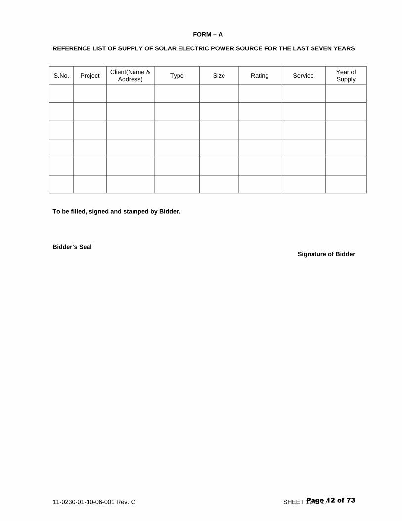
FORM – A
REFERENCE LIST OF SUPPLY OF SOLAR ELECTRIC POWER SOURCE FOR THE LAST SEVEN YEARS
S.No. Project Client(Name & Address) Type Size Rating Service Year of
Supply
To be filled, signed and stamped by Bidder. Bidder’s Seal Signature of Bidder
Page 12 of 73

11-0230-01-10-06-001 Rev. C SHEET 13 of 17
FORM – B
LIST OF SPARES & ACCESSORIES FOR START UP & COMMISIONING FOR SOLAR ELECTRIC POWER SOURCE
S.No. Item No. Description Quantity
Note: Bidder to include the start up and commissioning spares for Solar Electric Power Source in the quoted price.
To be filled, signed and stamped by Bidder. Bidder’s Seal Signature of Bidder
Page 13 of 73

11-0230-01-10-06-001 Rev. C SHEET 14 of 17
FORM - C LIST OF SPARES AND ACCESSORIES FOR TWO YEARS OF NORMAL OPERATION FOR SOLAR ELECTRIC POWER SOURCE
S.No. Item No. Description Quantity
Note: Bidder shall quote separately spares for normal operation for Solar Electric Power Source as per price schedule Performa.
To be filled, signed and stamped by Bidder. Bidder’s Seal Signature of Bidder
Page 14 of 73
11-0230-01-10-06-001 Rev. C SHEET 15 of 17
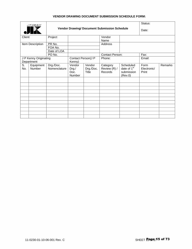
VENDOR DRAWING DOCUMENT SUBMISSION SCHEDULE FORM:
Vendor Drawing/ Document Submission Schedule Status: Date:
Client Project Vendor Name
PR No. FOA No. Date of LOA
Address Item Description
PO No. Contact Person: Fax: J P Kenny Originating Department
Contact Person(J P Kenny)
Phone: Email:
S. No.
Equipment Number
Drg./Doc. Nomenclature
Vendor Drg./ Doc. Number
Vendor Drg./Doc. Title
Category Review (R) / Records
Scheduled date of 1st submission (Rev.0)
Form Electronic/ Print
Remarks
Page 15 of 73
GAIL (India) Limited CHAINSA - JHAJJAR PIPELINE PROJECT
CLIENT JOB NO. 110230TECHNICAL SPECIFICATION FOR
SOLAR ELECTRIC POWER SYSTEM TOTAL SHEETS 11
DOCUMENT NO 11 0230 01 10 02 002
B 26/08/08 ISSUED FOR TENDER SB SP PKS A 02/07/08 ISSUED FOR REVIEW SB SP PKS
REV DATE DESCRIPTION PREP CHK APPR
Page 16 of 73

Document No. Rev
11-0230-01-10-02-002 B
TECHNICAL SPECIFICATION FOR
SOLAR ELECTRIC POWER SYSTEM SHEET 2 of 11
CONTENTS
1. SCOPE 2. CODES AND STANDARDS 3. SITE CONDITIONS 4. SCOPE OF SUPPLY 5. TECHNICAL REQUIREMENT 6. TESTING AND INSPECTION 7. VENDOR DATA REQUIREMENTS 8. CERTIFICATION 9. PACKING AND TRANSPORATION
Page 17 of 73
Document No. Rev
11-0230-01-10-02-002 B
TECHNICAL SPECIFICATION FOR
SOLAR ELECTRIC POWER SYSTEM SHEET 3 of 11
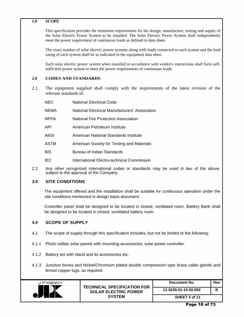
1.0 SCOPE
This specification provides the minimum requirements for the design, manufacture, testing and supply of the Solar Electric Power System to be installed. The Solar Electric Power System shall independently meet the power requirement of continuous loads as defined in data sheet. The exact number of solar electric power systems along with loads connected to each system and the load rating of each system shall be as indicated in the equipment data sheet. Each solar electric power system when installed in accordance with vendor's instructions shall form self-sufficient power system to meet the power requirements of continuous loads.
2.0 CODES AND STANDARDS 2.1 The equipment supplied shall comply with the requirements of the latest revision of the relevant standards of:
NEC National Electrical Code NEMA National Electrical Manufacturers' Association NFPA National Fire Protection Association API American Petroleum Institute ANSI American National Standards Institute ASTM American Society for Testing and Materials BIS Bureau of Indian Standards IEC International Electro-technical Commission
2.2 Any other recognized international codes or standards may be used in lieu of the above, subject to the approval of the Company. 3.0 SITE CONDITIONS
The equipment offered and the installation shall be suitable for continuous operation under the site conditions mentioned in design basis document.
Controller panel shall be designed to be located in closed, ventilated room. Battery Bank shall be designed to be located in closed, ventilated battery room.
4.0 SCOPE OF SUPPLY 4.1 The scope of supply through this specification includes, but not be limited to the following: 4.1.1 Photo voltaic solar panels with mounting accessories, solar power controller. 4.1.2 Battery set with stand and its accessories etc. 4.1.3 Junction boxes and Nickel/Chromium plated double compression type brass cable glands and
tinned copper lugs, as required.
Page 18 of 73

Document No. Rev
11-0230-01-10-02-002 B
TECHNICAL SPECIFICATION FOR
SOLAR ELECTRIC POWER SYSTEM SHEET 4 of 11
4.1.4 Flame retardant low smoke (FRLS) type interconnecting cables between solar panels and main junction boxes, as required.
5.0 TECHNICAL REQUIREMENTS 5.1 POWER SYSTEM
Power system shall include the following equipment: 5.1.1 Photovoltaic solar cell array (Solar panels). 5.1.2 Battery Bank 5.1.3 Solar power controller
The solar power system shall be self sustained type.
The photovoltaic solar cell array (solar panels) and the solar controller shall be sized to meet through battery back-up, the load cycle requirements of the connected loads with the solar energy availability at site under worst weather conditions. The load requirement per day shall be determined on the basis of load data specified in the data sheet.
5.2 SOLAR PANELS
The photovoltaic solar panel array shall consist of required number of individual solar panels. The individual photovoltaic elements shall be connected in suitable series-parallel combinations to obtain the required voltage and current rating of a solar module. Individual solar modules shall be connected in suitable series-parallel combinations to obtain the required voltage and current rating of a solar panel. Solar panel array shall consist of required number of panels in series-parallel combination to meet the system requirements. Solar panels will be mounted on steel support structure of suitable height on the control room rooftop. The solar panel array shall be designed based upon Isolation Data (to be gathered by contractor from metrological department) and following design conditions: i) Output current to be considered at operating point based on following operating conditions: a) Cell temperature while delivering current corresponding to Pmax point on the I-V curve at specified ambient temperature. b) Operating voltage considering: - Charging voltage of the battery. - Voltage drop in cables between solar array and solar controller and solar controller and battery. - Voltage losses in solar controller. - Negative tolerance, if any, on the output voltage at solar controller. After working out the output current at operating point, the following de-rating factors shall be applied: a) Deterioration factor over life span or 15% whichever is higher. b) Losses due to dust deposit or 1% whichever is higher. c) Losses due to module/branch mismatch or 2% whichever is higher. d) Losses due to line resistance cables (panel to controller). e) Losses in field wiring and array wiring. f) Losses in solar controller.
Page 19 of 73

Document No. Rev
11-0230-01-10-02-002 B
TECHNICAL SPECIFICATION FOR
SOLAR ELECTRIC POWER SYSTEM SHEET 5 of 11
g) Battery charge/discharge efficiency or 93% whichever is lower. h) Any other de-rating factor considered essential for satisfactory and guaranteed
performance of Solar Power System (e.g. negative tolerance on nominal rating of solar panels)
i) De-rating factor of 2% or as applicable (whichever is higher) to account for panel orientation other than the specified one as per insolation data.
j) The solar panels shall be able to fully charge the battery bank after "3 NO SUN DAYS" cycle from the surplus power available from the solar panel in next 14 days with 70% Depth of Discharge of battery.
5.2.1 Panel Construction
The Solar modules shall have suitable encapsulation and sealing arrangements to protect the Silicon elements (Cells) from the environment. The arrangement and material of encapsulation shall be compatible with the thermal expansion properties of the silicon cells and the module framing arrangement/ material. The encapsulation arrangement shall ensure complete moisture proofing for the entire life of the solar modules. The solar panel shall have suitable supporting arrangement complete with adjustable mounts, solar module fixing accessories, inter-module connections, cable termination arrangement, double compression, nickel/chromium plated, brass cable glands and all other necessary equipment and hardware. The supporting arrangement shall be such as to utilize minimum space on the control room rooftop. Unless specified otherwise width of the walkway is 1600mm. The panel dimension and its supporting structure shall be so sized as to leave a dear walking space of minimum 750mm. Materials used in the construction of panel frame to support the solar modules, supporting structure and all other accessories shall be suitable for location in extremely corrosive, dusty environment to be encountered. The solar module framing shall be copper free aluminium alloy. Arrangement, such as, vertical stainless steel rods or flexible rods shall be provided to prevent bird landing on the panels. Each panel shall be provided with a weatherproof Junction box with minimum IP 55 enclosure with removable gasketed front cover for termination of external cables. The electrical terminals in the junction box shall be corrosion proof and anti-loosening type. Suitable bypass diodes shall be provided for partial shadowing of modules, if recommended by manufacturer. Suitable arrangement (Stands/stairs) shall be made to facilitate day to day cleaning of solar cell.
5.3 BATTERY BANK 5.3.1 Battery Cells
The battery bank shall be charged from the surplus power available from the solar panel when the sunlight is available and will supply/supplement the solar electric power from the solar panel when the sunlight is inadequate under cloudy condition and during nights. The battery cells shall be low self discharge (up to 3% at 27°C per month) Ni-Cd suitable for photo voltaic application. The battery cells shall be provided with flame arresting type catalytic caps or ceramic plugs. The type of battery cells shall be as specified in equipment data sheet. The battery shall incorporate the following features:
- High charging efficiency. - Good cycle life even for deep discharge. - Extended life expectancy. - Large electrolyte reservoir.
Page 20 of 73
Document No. Rev
11-0230-01-10-02-002 B
TECHNICAL SPECIFICATION FOR
SOLAR ELECTRIC POWER SYSTEM SHEET 6 of 11
The type, AH capacity and no. of cells in the battery bank shall be decided on the following basis: i) Geographical and climatic conditions prevalent at site. ii) Back-up during low insolation periods considering the de-rated solar panel output and insolation data. iii) Unless specified otherwise, the system voltage shall be 24 V (Nominal). v) Battery suitable for 4000 or more charge-discharge cycle for 10% depth of discharge and for 1600 or more charge discharge cycle for 70% depth of discharge. v) 70% Depth of Discharge. vi) Minimum 3 days back-up to independently feed the load plus losses, if any. vii) Design ambient temperature-minimum and maximum site temperatures as given in Specification- "Site Conditions and Climate". viii) Deterioration factor over the life span (Actual or 20% whichever is higher).
x) Self discharge during low insolation periods considering average ambient temperature of 30°C. The battery shall be able to recoup full charge from surplus power available from solar cell in normal operating condition in day to day basis i.e., battery discharged during no sun period (in sunny day) should be recoup full charge during sunny period in the next day itself.
The battery shall be able to fully charge after "3 NO SUN DAYS" cycle from surplus power available from the solar panel in next 14 days with 70% depth of discharge.
5.3.2 General requirements and Performance for Ni-Cd Batteries shall be as per JPK standard spec. 5.4 SOLAR POWER CONTROLLER 5.4.1 Technical requirements
The solar power controller shall regulate the charge of the battery and shall monitor the charging current from the solar array. Power from the battery set & solar arrays shall be routed through the solar controller. The controller shall be provided with low loss type, high efficiency, tested and tropicalized components with overall loss of the solar controller not exceeding 10% of the rated load. MCCBs and MCBs shall be used for the circuit or device protection in place of fuses. However, semiconductor grade fuses shall be used for diodes, SCRs etc. Unless specified otherwise, the solar controller shall be wall mounted type with hinged and gasketed door in the front. The cable entry shall be from top or bottom (to be decided at the time of detailed engineering) through glands and access to all inside equipments shall be from the front only. The supply system shall be suitable for both negative earthed and unearthed system as required. The provision of negative earthing shall be through an isolating link. Apart from required control elements, the following components/ features shall be provided in the controller as a minimum requirements: i) A 2-Pole MCCB with shunt trip to isolate the solar panel from the solar controller/battery
on receipt of 60% LEL signal from the gas detection panel. (The signal will be in the form of a normally open potential-free contact).
ii) The battery bank shall be automatically disconnected from the solar panels when the
state of charge of the battery reaches 110% or maximum permissible charge level (as
Page 21 of 73
Document No. Rev
11-0230-01-10-02-002 B
TECHNICAL SPECIFICATION FOR
SOLAR ELECTRIC POWER SYSTEM SHEET 7 of 11
indicated by the battery manufacturer) and from the load when the depth of discharge reaches 70%. The battery bank shall be automatically reconnected to the Solar Panel when the state of charge of the battery drops to 100%.
iii) Ammeters to measure load current and solar array current. iv) An array fault indicator to indicate solar array failure. v) Voltmeter to indicate system output voltage and Battery voltage. vi) Charge-discharge Ammeter. vii) Battery deep discharge alarm and indication. viii) Control circuit fail alarm and indication. ix) Switches mounted on the front to disconnect all alarms and indications. x) Necessary transducers for providing two wire 4-20 mA signals for the following
parameters :
- Battery voltage - Solar array current - Battery charging current - Load current - Solar panel fault indicators
xi) Current limiting features with active elements. xii) Voltage regulator shall be switching mode type.
xiii) Digital Ampere hour meter.
Protection features to take care of faults in DCDB bus, solar controller, solar panel, battery circuit etc.
5.4.2 General Requirements 5.4.2.1 Panel Construction
The panel shall be fabricated out of minimum 14 SWG sheet steel. The degree of protection of enclosure shall be IP-51 minimum. Panels shall be provided with necessary lifting hooks and mounting brackets/base channels
5.4.2.2 Wiring
The wiring shall be done with minimum 2.5 mm2 PVC insulated copper wire of 650 volts grade. Wiring to door mounted devices shall be with flexible wires. Wire lugs shall be of crimping type. Bundles of wires shall be routed neatly in vertical or horizontal planes. Individual wires and bundles shall be secured with PVC wire ties, cable lacings or by enclosing in PVC wire trays. Unless specified otherwise, all terminal blocks shall be rated for minimum 20A at 650 volts. The terminal block shall have a white plastic marking strip of the length of the terminal block. Each terminal block assembly shall have 20% spare terminals. All wiring shall be identified by permanent slip-on or clip-on marking sleeves on each terminating wire in addition to marking at the terminal block.
5.4.2.3 Bus Bars
Page 22 of 73
Document No. Rev
11-0230-01-10-02-002 B
TECHNICAL SPECIFICATION FOR
SOLAR ELECTRIC POWER SYSTEM SHEET 8 of 11
Bus bars shall be sufficiently sized and adequately braced for the supply conditions specified in data sheet. The bus bars shall be electrolytic copper and shall be sleeved with 1100V grade suitable sleeve. Bus joints shall be bolted type and insulated by flame-retardant insulation tape.
5.4.2.4 Earthing
An earth bus bar of minimum 25mm x 3mm size made of electrolytic copper shall be provided, running the complete length of the solar controller. All non current carrying parts shall be bonded with flexible copper wires with the earth bus. The earth bus shall have provisions at both ends for connecting it to earth grid conductor.
5.4.2.5 Segregation
All electrical devices and live parts in the solar controller panel shall be segregated by means of metallic screens. All power connections in case of solar controller shall be segregated from one another and from the electronic circuits
5.4.2.6 Cabling
All interconnecting cables between various solar panels and main JBs, included in scope of supply, shall be Flame Retardant Low Smoke (FRLS) type. Cables of sizes, as specified, connecting JBs to solar controller, solar controller to battery shall be supplied by contractor. Adequate space shall be provided for termination of external cables. All required Nickel-Chromium plated brass double compression cable glands and tinned copper lugs shall be included in the scope of supply.
5.5 MATERIALS AND FINISH
All materials shall be selected and finished to resist the site conditions and climate specified in Job Specification. All electronic circuit boards shall be tropicalised to prevent corrosion and fungus growth. Painting shall be suitable for the requirements specified in Job Specification.
5.6 IDENTIFICATION All solar panels, batteries, solar controller and related devices and materials shall have permanent tags in contrasting colours affixed on them and lettering of at least 12 mm size. The tag inscription shall be in line with the equipment number list.
6.0 TESTING AND INSPECTION
All tests shall be carried out as per relevant standards at Vendor's works.
The company reserves the right to have a representative to witness the final testing and inspection. Prior intimation of at least 20 days shall be given to enable the Company depute its representative to witness the tests. Testing and inspection shall include but not necessarily limited to the following:
6.1 GENERAL (FOR ALL ITEMS) 6.1.1 A quantitative check to ensure that all items in specified quantity are present. 6.1.2. A visual inspection to check workmanship and compliance with submitted drawings. 6.1.3. Dimensional checks
Page 23 of 73

Document No. Rev
11-0230-01-10-02-002 B
TECHNICAL SPECIFICATION FOR
SOLAR ELECTRIC POWER SYSTEM SHEET 9 of 11
6.2 SOLAR PANELS 6.2.1 Following environmental tests as per applicable IEC/IS shall be carried out on photovoltaic
modules on sampling basis. Minimum 2% of ordered modules or 1 No. module, whichever is higher, shall be subjected to following tests and performance of module before and after each test shall be tabulated and furnished. The tests shall be carried out sequentially on each module selected for testing and the tested module shall be discarded after tests.
In case on account of testing: i) The overall deterioration in the performance of the tested modules after test exceed
5% of rated performance, or ii) The tested module exhibits any open circuits and or ground faults, or iii) The tested module develops cracks or mechanical damage, or iv) The tested module fails to pass the electrical isolation tests The entire ordered lot of modules shall be rejected.
S.No. Test Test Details 1. Cold Temp.:(-) 40ºC
Duration: 16 Hrs.
2. Rapid Change of Temp.
Low Temp.:(-) 40ºC High Temp:+ 85ºC No. of cycles: 10 Duration of Exposure:30 Min.
3. Dry heat Temp.: 85ºC Duration : 16 Hrs. 4. Salt mist Temp.: + 35ºC Duration:48 hrs. 5. Wind Pressure equivalent to an air velocity of
280km/hr. 6. Rain Test as required in the mentioned
standards 7. Dust Test as required in the mentioned
standards 8. Composite
/Humidity Test Test as required in the mentioned standards
9* Mould Growth 84 days 10* Hail Storm test Test as required in the mentioned
standards 11* Shock Test Peak Acceleration : 490m/sec² Duration :
11 msec.
* Vendor shall submit the test procedure for owner’s review. Vendor shall indicate test conditions like temperature limits and duration etc. and also mention the name of the applicable standards.
6.2.2 The following design qualification tests shall also be conducted : i) Earth continuity test. ii) Electrical isolation test. iii) * Hot spot endurance test.
Page 24 of 73

Document No. Rev
11-0230-01-10-02-002 B
TECHNICAL SPECIFICATION FOR
SOLAR ELECTRIC POWER SYSTEM SHEET 10 of 11
NOTE: Type test certificate can be accepted for the tests marked with asterisks (*). 6.3 BATTERY : Refer JPK Standard spec. 6.4 SOLAR CONTROLLER
Tests in the following order shall be conducted for the panel : i) General ii) Earth Continuity Test iii) Functional Tests iv) Insulation Resistance Measurement v) Heat Run Test vi) Functional Test
6.5 Burn out tests for 120 hrs. on the complete system in one assembly. 7.0 VENDOR DATA REQUIREMENTS 7.1 GENERAL
7.1.1* Make, type & catalogue no. of equipment. 7.1.2* Dimension, weight & general arrangement drawings. 7.1.3* Type test certificates. 7.1.4* Routine test certificates. 7.1.5 Applicable International Standards. 7.1.6 Installation, Operating & maintenance manual. 7.1.7 Hazards & safety precaution. 7.1.8* Catalogues & Brochures. 7.1.9 Interconnection diagram for various equipment along with cable size. 7.1.10* Bill of material. 7.1.11* Completed data sheet. 7.2 SOLAR PANELS 7.2.1* I-V characteristics (plotted on graph) indicating values of Voc, Isc. Voltage & current (at
Pmax point & operating point) of modules and arrays at 16°C, 28°C, 40°,60°C cell temperature, at 10 mW/cm2 and 100 mW/cm2 solar insolation.
7.2.2* Temperature co-efficient of voltage & current. 7.2.3* Solar panel sizing calculations. 7.2.4* Expected life span with 20% degradation in output power.
Page 25 of 73

Document No. Rev
11-0230-01-10-02-002 B
TECHNICAL SPECIFICATION FOR
SOLAR ELECTRIC POWER SYSTEM SHEET 11 of 11
7.2.5 Detailed calculations to verify suitability of structure to withstand wind velocities of
280 km/hr. 7.3 BATTERY SET : 7.3.1* Various characteristics curves not limited to the following :
a) Charging-discharging characteristics at various cell voltage & temperature. b) Self discharge at various ambient temperatures. c) Cell voltage V/s. State of charge. d) Capacity V/s. rate of discharge. e) State of charge V/s. Sp. Gravity of electrolyte. f) Depth of discharge V/s. no. of cycles.
7.3.2* Selection criteria including sizing calculation. 7.3.3* Recommended float charging voltage & current. 7.3.4 Memory effect (if any). 7.4 SOLAR CONTROLLER 7.4.1 Operational write up. 7.4.2 Schematic & wiring diagrams. 7.4.3 Expected temperature at critical points for maximum load.
NOTE: 1. Items marked with asterisks (*) must be furnished along with bids. All other items
including the above shall be submitted for Company’s approval/information during detailed engineering.
2. All calculations furnished during bid stage shall be for information only. They shall be
checked during detailed engineering stage. Any change in size of battery, solar panel etc. shall be done without any price implication.
8.0 CERTIFICATION
All offered equipments or equipments of similar design manufactured by the same supplier : - Shall have been type tested by an independent authority. - Shall have been in continuous satisfactory service for a minimum period of two years. - Shall be having current certification/approval/listing by an approved agency.
9.0 PACKING AND TRANSPORTATION
The offered equipments along with accessories shall be shipped to site packed in wooden crates. They shall be wrapped with polythene sheets, before being placed in the crates to prevent damage to finish. Crates shall have skid bottom for handling.
Page 26 of 73

GAIL (India) Limited CHAINSA - JHAJJAR PIPELINE PROJECT
CLIENT JOB NO. 110230TECHNICAL SPECIFICATION FOR
LT POWER & CONTROL CABLES TOTAL SHEETS 13
DOCUMENT NO 11 0230 01 10 02 004
B 26/08/08 ISSUED FOR TENDER SB SP PKS A 02/07/08 ISSUED FOR REVIEW SB SP PKS
REV DATE DESCRIPTION PREP CHK APPR
Page 27 of 73

Document No. Rev
11-0230-01-10-02-004 B
TECHNICAL SPECIFICATION
FOR LT POWER & CONTROL CABLE SHEET 2 of 13
CONTENTS
1. SCOPE 2. STANDARDS 3. GENERAL CONSTRUCTION 4. CABLES ACCESSORIES 5. INSPECTION, TESTING AND ACCEPTANCE 6. MISCELLENOUS MATERIAL SPECIFICATIONS 7. CABLE LAYING 8. TERMINATIONS 9. TESTING 10. PACKING AND DESPATCH
Page 28 of 73
Document No. Rev
11-0230-01-10-02-004 B
TECHNICAL SPECIFICATION
FOR LT POWER & CONTROL CABLE SHEET 3 of 13
1.0 SCOPE
This specification along with data sheets covers requirements for design, manufacture, testing at works and supply of Flame Retardant Low Smoke (FRLS) PVC cables and cable terminating accessories for medium voltage systems.
2.0 STANDARDS 2.1 The cables and cables jointing & terminating accessories shall comply with the latest edition of the following standards as applicable: IS: 1554 [Part-I] PVC insulated (heavy duty) electric cables. IS: 7098 Cross-linked polyethylene insulated PVC sheathed. IS: 8130 Conductors for insulated electric cables and flexible cords. IS: 5831 PVC insulation and sheath of electric cables. IS: 3975 Mild steel wires, strips and tapes for armouring of cables. 10810(Part 41) Methods of test for cables: Mass of zinc coating on steel armour. IS: 209 Specification for zinc.
IS: 3961(Pt-2) Recommended current ratings for cables: Part - 2 PVC Insulated and PVC sheathed heavy-duty cables. IS: 10418 Drums for electric cables. IS: 10462 (Pt-I) Fictitious calculation method for determination of Dimensions of protective coverings of cables: Part - I Electrometric and thermoplastic insulated cables IS: 10810 (Pt-58) Oxygen Index test. IS: 10810 (Pt 61) Flame Retardant test. IS: 10810 (Pt 62) Fire resistance test for bunched cables. IEC: 60332-3 Tests on electric cables under fire conditions. IEC: 60502 Extruded solid dielectric insulated power cables for rated Voltages from 1 kV.up to 30 kV. IEC: 60540 & 60540A Test methods for insulation and sheaths of electric Cables. ASTM: D2863 Standard method of test for flammability of plastics using oxygen index method. ICEA S-61-402 Thermoplastic insulated wire and cable for transmission and distribution of NEMA-WC5 electrical energy. ICEA S-66-524 Cross-linked thermosetting polyethylene insulated wire and cable for NEMA-WC7 transmission and distribution of electrical energy.
SP: 30 (BIS) Special Publication – National Electrical Code. IS: 10810 Method of Test for cables; Part 43 Insulation resistance.
(Part 43) IS: 10810 Method of Test for cables: Part 45 High voltage test. (Part 45) OISD 147 Inspection and safe practice during electrical installation OISD 173 Fire prevention and protection system for electrical installation 2.2 In addition to the above it shall be ensured that the installation conforms to the requirements of
the following as applicable: a. Indian Electricity Act and Rules. b. Regulations laid down by CEA/Electrical Inspectorate.
c. Regulations laid down by CCE/DGMS (as applicable).
Page 29 of 73
Document No. Rev
11-0230-01-10-02-004 B
TECHNICAL SPECIFICATION
FOR LT POWER & CONTROL CABLE SHEET 4 of 13
d. The petroleum rules (Ministry of Industry Government of India). e. Any other regulations laid down by central/state/local authorities and Insurance agencies.
2.3 The cables and accessories shall also conform to the provisions of Indian Electricity Rules and other statutory regulations, as applicable. 2.4 In case of any contradiction between various referred standard/ specification/data sheet and
statutory regulations, the following order of priority shall govern: Statutory Regulations Data Sheets Job Specifications This Specification Codes and Standards
3.0 GENERAL CONSTRUCTION 3.1 The cables shall be suitable for laying in trays, trenches, ducts, and conduits and for underground-buried
installation with uncontrolled backfill and possibility of flooding by water and chemicals. 3.2 Outer sheath of all PVC cables shall be black in colour and the minimum value of oxygen index shall be
29 at 27 ± 2º C. In addition suitable chemicals shall be added into the PVC compound of the outer sheath to protect the cable against rodent and termite attack.
3.3 All cables covered in this specification shall be Flame Retardant Low Smoke(FRLS) unless specified otherwise in the data sheet. The outer sheath of PVC and XLPE cables shall possess flame propagation properties meeting requirements as per IS-l0810 (Part-62) category AF. 3.4 Sequential marking of the length of the cable in metres shall be provided on the outer sheath at every one
metre. The embossing / engraving shall be legible and indelible.
3.5 The overall diameter of the cables shall be strictly as per the values declared by the manufacturer in the technical information subject to a maximum tolerance of ±2 mm up to overall diameter of 60mm and ±3mm for beyond 60mm.
3.6 PVC I Rubber end caps shall be supplied free of cost for each drum with a minimum of eight per thousand metre length. In addition, ends of the cables shall be properly sealed with caps to avoid ingress of water during transportation and storage. 3.7 The cables used in installations under the jurisdiction of Director General of Mines and Safety (DGMS) shall be of copper conductor only, and shall have valid DGMS approvals for the specified locations. The word" Mining Cable" shall be embossed / engraved on the cable outer sheath as per the
applicable Indian Standards
3.8 PVC cables 3.8.1 All power/control cables for use on medium voltage systems shall be heavy-duty type, 650/1100 V grade
with aluminium I copper conductor, PVC insulated, inner-sheathed, armoured and overall PVC sheathed unless specified otherwise in data sheet.
Page 30 of 73

Document No. Rev
11-0230-01-10-02-004 B
TECHNICAL SPECIFICATION
FOR LT POWER & CONTROL CABLE SHEET 5 of 13
3.8.2 The conductors shall be solid for conductor of nominal area up to and including 6mm2 and stranded beyond 6mm2. Conductors of nominal area less than 16 mm2 shall be circular only. Conductors of nominal area 16 mm2 and above may be circular or shaped as per IS 8130. Cables with reduced neutral conductor shall have sizes as per Table I of IS 1554 (Part-I).
3.8.3 The core insulation shall be with PVC compound applied over the conductor by extrusion and shall
conform to the requirements of type 'A' compound as per IS: 5831. The thickness of insulation and the tolerance on thickness of insulation shall be as per Table 2 of IS: 1554 (Part-I). Control cables having 6 cores and above shall be identified with prominent and indelible Arabic numerals on the outer surface of the insulation. Colour of the numbers shall contrast with the colour of insulation with a spacing of maximum 50 mm between two consecutive numbers. Colour coding for cables up to 5 cores shall be as per Indian standard.
3.8.4 The inner sheath shall be applied over the laid-up cores by extrusion and shall be of PVC conforming to
the requirements of Type ST-l PVC compound as per IS: 5831. The minimum thickness of inner sheath shall be as per IS: 1554 (Part-I). Single core cables shall have no inner sheath.
3.8.5 If armouring is specified for multicore cables in the data sheet, the same shall be by single round
galvanised steel wires where the calculated diameter below armouring does not exceed 13 mm and by galvanised steel strips where this dimension is greater than 13 mm .. Requirement and methods of tests for armour material and uniformity of galvanisation shall be as per IS - 3975 and IS -10810 (Part 41). The dimensions of Armour shall be as per method (b) of IS - 1554 (Part -1). If armouring is specified for single core cables in the data sheet, the same shall be with H4 grade hard drawn aluminium round wire of 2.5 mm diameter.
3.8.6 The outer sheath for the cables shall be applied by extrusion and shall be of PVC compound conforming
to the requirements of type ST-1 compound as per IS: 5831. The minimum and average thickness of outer sheath for unarmoured cables and minimum thickness of outer sheath for armoured cables shall be as per IS: 1554 (Part -1).
3.8.7 If heat resisting PVC cables are specified in the data sheet, the following shall be the requirements: It shall be possible to continuously operate the cable at a maximum conductor temperature of 85º C. PVC compounds used for HR PVC cables shall be as follows: a. Conductor insulation - Type C b. Inner sheath - Type ST 2 c. Outer sheath - Type ST 2 3.9 Control Cables:
Control cables shall be 1100 Volt Grade, 2.5 mm2 copper conductor PVC insulated PVC sheathed FRLS, single wire armored with an overall PVC sheath, as per IS: 1554 pt. I. Unarmored cables shall be used wherever specified on the cable schedule.
4.0 CABLE ACCESSORIES 4.1 The termination and straight through jointing kits for use on the systems shall be suitable for the type of
cables offered as per this specification. 4.2 The accessories shall be supplied in kit form. Each component of the kit shall carry the manufacturer's
mark of origin. 4.3 The kit shall include all stress grading, insulating and sealing materials apart from conductor fittings
and consumable items .An installation instruction sheet shall also be included in each kit.
Page 31 of 73
Document No. Rev
11-0230-01-10-02-004 B
TECHNICAL SPECIFICATION
FOR LT POWER & CONTROL CABLE SHEET 6 of 13
4.4 The contents of the accessories kit including all consumable shall be suitable for storage without
deterioration at a temperature of 45° C, with shelf life extending to more than 5 years .. 4.5 Terminating kits The terminating kits shall be suitable for termination of the cables to an indoor switchgear or to a
weatherproof cable box of an outdoor mounted transformer / motor. For outdoor terminations, weather shields / sealing ends and any other accessories required shall also form part of the kit. The terminating kits shall be from one of the makes / types mentioned in the data sheet.
4.6 Jointing kits The straight through jointing kits shall be suitable for installation on overhead trays, concrete lined
trenches, and ducts and for underground burial with uncontrolled backfill and possibility of flooding by water and chemicals. These shall have protection against any mechanical damage and suitably designed to be protected against rodent and termite attack. The inner sheath similar to that provided for cables shall be provided as part of straight through joint. The jointing kits shall be from one of the makes / types mentioned in the data sheet.
5.0 INSPECTION, TESTING AND ACCEPTANCE
The cables shall be tested and inspected at the manufacturer's works. All the materials employed in the manufacture of the cable shall be subjected, both before and after manufacture, to examination, testing and approval by JPK / owner. Manufacturer shall furnish all necessary information concerning the supply to JPK / owner's inspectors. The inspector shall have free access to the manufacturer's works for the purpose of inspecting the process of manufacture in all its stages and he will have the power to reject any material, which appears to him to be of unsuitable description or of unsatisfactory quality. The vendor shall give at least 2 weeks advance notice to the purchaser, regarding the date of testing to enable him or his representative to witness the tests.
5.1 Cables 5.1.1 After completion of manufacture of cables and prior to despatch, the cables shall be subjected to type,
routine, acceptance and special tests as detailed below. JPK/ Owner reserves the right to witness all tests with sufficient advance notice from vendor. The test reports for all cables shall be got approved from the Engineer before despatch of the cables.
5.1.2 All routine tests, acceptance tests, type tests and additional type tests for improved fire performance
shall be carried out as listed in IS: 1554 (Part-I), and IS: 7098 (Part-2) on PVC and XLPE insulated cables respectively.
5.1.3 The test requirements for PVC insulation and sheath of cables shall be as per latest revision of IS: 5831 5.1.4 Test for Resistance to Ultra Violet Radiation: This test shall be carried out as per DIN 53387 or ASTM-
G-53 on outer sheath. The retention value of tensile strength and ultimate elongation after the test shall be minimum 60 % of tensile strength and ultimate elongation before the test. Test certificates with respect to this test (not older than one year) from recognised testing laboratory to be furnished for review by JPK before despatch clearance of cables. In case test certificates are not available, test is to be conducted by vendor at his own cost in any recognised test laboratory or in house testing laboratory, before despatch clearance of cables. Sampling for this test is to be done randomly once for each order, provided outer. sheath remains same.
5.1.5 Acceptance tests as per IS-1554 (Part-I) and IS-7098 (Part-2) and the following special tests to be
performed on the cables as per sampling plan. These tests are required to be witnessed by JPK/owner before despatch of cables.
Page 32 of 73

Document No. Rev
11-0230-01-10-02-004 B
TECHNICAL SPECIFICATION
FOR LT POWER & CONTROL CABLE SHEET 7 of 13
a. Accelerated water absorption test for insulation as per NEMA - WC - 5. (For PVC insulated
cables) and as per NEMA WC - 7 (for XLPE insulated cables). Test certificates with respect to. this test (not older than one year) from recognised testing laboratory to be furnished for review by JPK before despatch clearance of cables. In case test certificates are not available, test is to be conducted by vendor at his own cost in any recognized test laboratory or in house testing laboratory, before despatch clearance of cables. Sampling for this test is to be done randomly once for each order, provided type of insulation remains same.
b. Dielectric Retention Test: The dielectric strength of the cable insulation tested in accordance with
NEMA WC - 5 at 75 ± 10 e shall not be less than 50 % of the original dielectric strength. (For PVC insulated cables). Test certificates with respect to this test (not older than one year) from recognised testing laboratory to be furnished for review by JPK before despatch clearance of cables. In case test certificates are not available, test is to be conducted by vendor at his own cost in any recognized test laboratory or in house testing laboratory, before despatch clearance of cables. Sampling for this test is to be done randomly and once for each order.
c. Oxygen Index Test: The test shall be carried out as per ASTM D2863 or applicable Indian Standard specifications. Sampling to be done for every offered lot/size as per sampling plan.
d. Flammability Test: The test shall be carried out on finished cable as per IS - 10810 (part 61 &
62). Sampling for these tests is to be done randomly once for each order, provided outer sheath remains same. The acceptance criteria for tests conducted shall be as under: Part-61- The cable meets the requirement if there is no visible damage on the test specimen within 300 mm from its upper end. Part-62- The maximum extent of the charred portion measured on the test sample should not have reached a height exceeding 2.5 m above the bottom edge of the burner at the front of the ladder.
e. Test for rodent and termite repulsion property: The vendors shall furnish the test details to analyse the property by chemical method. Sampling to be done for every offered lot / size as per sampling plan.
5.2 Cable Accessories
Type tests should have been carried out to prove the general qualities and design of a given type of termination / jointing system as per IS-l3573. The type test certificates from independent testing laboratory shall be submitted before despatch.
6. MISCELLANEOUS MATERIAL SPECIFICATIONS
All materials and hardwares to be supplied by the contractor shall be new, unused and of best quality and shall conform to the latest specifications of Bureau of Indian Standards.
6.1 Cable Trays:
These shall be ladder type trays either prefabricated hot dip galvanized sheet steel trays or site fabricated angle iron painted trays as specifications of Bureau of Indian Standards.
6.1.1 Pre-fabricated hot dipped galvanized trays The cable trays shall comply to the requirements specified in JPK installation std. 6.1.2 Site fabricated angle iron trays
Angle iron cable trays shall be fabricated from standard rolled angle iron sections of size 75x75x8 for
Page 33 of 73
Document No. Rev
11-0230-01-10-02-004 B
TECHNICAL SPECIFICATION
FOR LT POWER & CONTROL CABLE SHEET 8 of 13
runners for supporting spans limited to 3000 mm. Cross support shall be 25 x 6 mm MS flat for tray width upto 500 mrn and 32 x 6 mm flat for tray of more than 500 mm wide and spacing between two cross supports shall not exceed 250 mm.
6.1.3 Vertical supports for both the prefabricated and site fabricated type trays shall be fabricated out of ISMC 100 and horizontal supports shall be with 65 x 65 x 6 mm angle iron sections. Outer most tier of all vertical cable trays shall be covered with GI sheet for protection against physical damage to cables.
Cable racks and trays shall be covered by removable top covers on upper most tier allowing adequate ventilation in following cases where : - Mechanical damage of cables is likely to occur during maintenance in the plant. - Oil or spillage of chemicals can be expected. - Protection from exposure to sun is required. GI cover sheet shall allow adequate ventilation to the cables and shall be in standard length of 3000 mm, flanged on both sides for fixing on cable tray. Covers shall be complete with required GI hardwares.
6.2 Cable Glands:
Cable glands shall be of nickel plated brass unless otherwise specified. The single compression type cable glands shall be used for indoor panels/equipment (e.g. substation, control room etc). The cable glands for outdoor terminations shall be weather protected, double compression type and shall have PVC shroud for additional weather protection. Cable glands forming a part of relevant FLP enclosure shall be FLP type, tested by CMRI or any other recognized independent testing laboratory and approved by CCE/DGMS or any other statutory authority as applicable. Indigenous FLP glands shall have valid BIS license as per the requirements of statutory authorities. The size of cable glands supplied shall be appropriate to the size of cable so that flame proofness of glands is retained. Entry thread of cable gland shall be compatible to the entry thread provided in the equipment (BS, ET, NPT, PG as applicable). If required, suitable reducers/adopters shall be used.
6.3 Connectors:
Power cable terminations shall be made with crimped type tinned copper solderless lugs which shall be suitable for the cable size mentioned in cable schedule.
6.4 Ferrules:
Ferrules shall be of approved type and of size to suit core size mentioned and shall be employed to designate the various cores of control cable by the terminal numbers to which the cores are connected, for ease of identification.
7. CABLE LAYING 7.1 General
Cable installation shall include power, control, lighting etc. cables. These shall be laid in trenches/ cable trays as detailed in the cable layout drawings. Cable routing given on the cable layout drawings shall be checked in the field so as to avoid interference with structures, heat sources, drains, piping, airconditioning duct etc. Any change in routing shall be done to suit the field conditions wherever deemed necessary, after obtaining approval of Engineer-in-charge.
Page 34 of 73
Document No. Rev
11-0230-01-10-02-004 B
TECHNICAL SPECIFICATION
FOR LT POWER & CONTROL CABLE SHEET 9 of 13
7.1.1 LT power and control cables shall be separated from each other by adequate spacing or by running through independent pipes, trenches or cables trays, as shown on layout drawings/installation standards. Details of cable routes and cable spacing not shown in detail on these drawing shall be determined by the contractor and approved by the engineer in-charge.
When single core cables are laid in flat formation, the individual cable fixing clamps and spacers shall be
of non-magnetic material. As a general practice, the sheath of single core cables shall be earthed at one point to keep sheath at earth potential unless otherwise stated. Single core cables, when laid in trefoil formation shall be braced by suitable clamps at a distance, not exceeding 3 meters along the cable routing.
The Telephone, Communication and Fire alarm cables shall run on instrument trays/ducts/ trenches in the units. Wherever these are not available, cables shall be taken in a separate trench/tray with a min. spacing of 600 mm from power and control cables but in any case such separation shall not be less than 300 mm. Telephone, fire alarm and plant communication cables shall be directly buried in road berm area, (unless otherwise specified in cable layout drawings) .. These cables shall cross power cables preferably at right angles. Street lighting cables shall be laid on the other side of road berm area
7.1.2 The lengths indicated in the cables schedule are only approximate. The contractor shall ascertain the exact
length of cable for a particular feeder by measuring at site. All cable routes shall be carefully measured. Before the start of cable laying, the contractor shall prepare cable drum schedule and get that approved by Engineer-in -charge to minimise/avoid straight through joints and then the cables cut to the required lengths, leaving sufficient lengths for the terminations of the cable at both ends. The various cable lengths cut from the cable reels shall be carefully selected to prevent undue wastage of cables. Extra loop length shall be given for feeder cables where required as per the directions of Engineer-in-charge to meet contingencies
Cables shall be laid in directly buried trench or in RCC trench (underground trench) or in cable tray along pipe sleeves as shown on cable layout drawings.
7.1.3 Cables shall be neatly arranged in the trenches / trays in such a manner that criss-crossing is avoided and final take off to the motor / switchgear is facilitated. Arrangement of cables within the trenches / trays shall be in line with cable layout drawings. Cable routing between cable trench and equipment/motors shall be taken through GI pipe sleeves of adequate size. Pipe sleeves shall be laid at an angle of maximum 45º to the trench wall. Bending radii of pipes shall not be less than 8D. It is to be ensured that both the ends of GI pipe sleeves shall be sealed with approved weather proof sealing plastic compound after cabling. In places where it is not possible, cables shall be laid in smaller branch trenches.
7.1.4 All cables shall be identified close to their termination point by cable tag numbers as per cable schedule.
Cable tag numbers shall be punched on aluminium straps (2mm thick, 20 mm wide and of enough length) securely fastened to the cable and wrapped around it.
Each underground cable shall be provided with cable tags of lead securely fastened every 30 m of its underground length with at least one tag at each end before the cable enters/leaves the ground. In unpaved areas, cable trenches shall be identified by means of cable markers as per installation drawing. These cable markers shall be placed at location of changes in the direction of cables and at intervals of not more than 30 m and also at cable straight through joint locations.
7.1.5 All temporary ends of cables must be protected against dirt and moisture to prevent damage to the
insulation. For this purpose, ends of cables shall be taped with an approved PVC end cap or rubber insulating tape.
7.1.6 Each row of cables shall be laid in place and before covering with sand. All wall openings/pipe sleeves
shall be effectively sealed after installation of cables to avoid seepage of water inside building/lined trench. Every cable shall be given an insulation test in presence of Engineer-in-charge/Owner before filling the cable trench with sand Any cable which is found defective shall be replaced.
Page 35 of 73

Document No. Rev
11-0230-01-10-02-004 B
TECHNICAL SPECIFICATION
FOR LT POWER & CONTROL CABLE SHEET 10 of 13
7.1.7 Where cables pass through foundation walls, the necessary openings shall be provided in advance for the same by another agency. However, should it become necessary to cut holes in existing structures for example floor slab etc., the electrical contractor shall determine their location and obtain approval of the Engineer-in-charge before carrying out the same.
7.1.8 Cables for road crossings shall be taken through ERC (Electrical Road Crossing) as shown in the cable
layout drawings.
At road crossing and other places where cables enter pipe sleeves adequate bed of sand shall be given so that the cables do not slack and get damaged by pipe ends.
7.1.9 Wherever cable trench crosses storm water, waste water channel/drain, cables shall be taken through
PVC/RCC pipes. Where cables are required to cross drains of depth more than 1200 mm, cables shall be taken over the drain on cable trays supported suitably using ISMC 150/200 sections.
7.1.10 Ends of cables leaving trench shall be coiled & capped and provided with protective cover till such time
the final termination to the equipment is completed. 7.2 Cables laid direct in ground
Cables shall be laid underground in excavated cable trenches where specified in cable layout drawings. Trenches shall be of sufficient depth and width for accommodation of all cables. Cables shall be properly spaced and arranged with a view of heat dissipation and economy of design. Maximum number of cable layers in trench shall be preferably limited to 5 layers.
Minimum depth of cable trench shall be 750 mm for LT Cables. The depth and the width of the trench shall vary depending upon the number of layers of cables as per JPK installation Standards
Cables shall be laid in buried trenches at depth as shown in the cable layout drawings. It is to be insured by the contractor that the bottom of buried trenches shall be cleared of all rocks, stones and sharp objects before cables are placed. The trench bottom shall be filled with a layer of sand. This sand shall be leveled and cables laid over it. These cables shall be covered with 150 mm of sand on top of the largest diameter cable and sand shall be lightly compacted. A flat protective covering of 75 mm thick second class red bricks shall then be laid and the remainder of the trench shall then be back -filled with soil, rammed and leveled.
7.3 Cables laid in concrete trench
Cables shall be laid in 3 or 4 tiers in concrete trench as shown on layout drawings. Concrete cables trenches shall be filled with sand in hazardous area to avoid accumulation of hazardous gases and oil. RCC covers of trenches shall be effectively sealed to avoid ingress of chemical and oil in process area. Removal of concrete covers where required for the purpose of cable laying and reinstating them in their proper position after cables are laid shall be done by electrical contractor.
All wall openings/pipe sleeves shall be effectively sealed after installation of cables to avoid seepage of water
7.4 Above ground cables 7.4.1 Cables installed above grade shall be run in cable trays, clamped on walls, ceiling or structures and shall
be run parallel or at right angles to beams, walls or columns. Cable routing shall be planned to be away from heat sources such as hot piping, gas, water, oil drainage piping, air-conditioning duct etc. Each cable tray shall contain only one layer of cables as far as possible for power cables. However control cables may be laid in double layer in the cable trays.
7.4.2 Individual cable or small group of cables (upto 3 to 4 cables) which run along structures / walls etc. shall
be clamped by means of 16 SWG GI saddles on 25 x 6 mm saddle bars. Alternatively small group of cables can be taken through 100/150 mm slotted channel tray / ISMC 100. Cables shall be supported so as
Page 36 of 73

Document No. Rev
11-0230-01-10-02-004 B
TECHNICAL SPECIFICATION
FOR LT POWER & CONTROL CABLE SHEET 11 of 13
to prevent sagging. In general, distance between supports shall be approximately 300 mm for cables upto 25 mm diameter and maximum 450 mm for cables larger than 25 mm dia. to prevent the sagging of cables.
7.4.3 Cable laid on supporting angle in cable trenches, structures, columns and vertical run of cable trays shall
be suitably clamped by means of G.I. saddles / clamps, whereas cables in horizontal run of cable trays shall be tied by means of nylon cords. Distance between supporting angles shall not exceed 600 mm.
7.4.4 All cable trays (other than galvanised trays) and supporting steel structures shall be painted before laying
of cables. The under surfaces shall be properly degreased, derusted, descaled and cleaned. The painting shall be done with one coat of redoxide zinc chromate primer. Final painting shall be done with two coats of approved bituminous aluminium paint unless otherwise specified.
7.4.5 Where cables rise from trench to motor, lighting panel, control station, junction box etc., they shall be
taken in GI pipe for mechanical protection upto a minimum of 300 mm above grade. Cable ends shall be carefully pulled through conduit to prevent damage to cable.
7.4.6 All G.I. Pipes shall be laid as per layout drawings and site conditions. Before fabrication of various
profiles of pipes by hydraulically operated bending machine (which is to be arranged by the contractor) all the burrs from the pipes shall be removed. GI Pipes having bends shall be buried in soil/concrete in such a way that the bend shall be totally concealed. For G.I. pipes buried in soil, bitumen coating shall be applied on the buried lengths, Installation of G.I. pipes shall be undertaken well before paving is completed and necessary co ordination with paving agency shall be the responsibility of Electrical Contractor.
Following guide shall be used for sizing of G.I. pipe. a) 1 cable in a pipe - 53% of pipe cross-sectional area occupied by cables. b) 2 cables in a pipe - 31% of pipe cross-sectional area occupied by cables. c) 3 cables in a pipe - 43 % of pipe cross-sectional area occupied by cables. d) 4 and above cables in a pipe - 40 % of pipe cross-sectional area occupied by cables. 7.4.7 After the cables are installed and all testing is complete, conduit ends above grade shall be plugged with a
suitable weatherproof plastic compound/bitumen/suitable sealing compound. Alternatively rubber bushes shall be employed for the purpose of sealing.
8. TERMINATIONS 8.1 All PVC cables up to 1100V grade shall be terminated at the equipment by means of compression type
cables glands suitable for the cable size. They shall have a screwed nipple with conduit electrical threads and check nut. The cables shall be identified close to their termination points at both the ends of cable(cable numbers shall be punched on aluminium straps 2 mm thick and securely fastened to the cable, wrapped around it) and also along the route at recommended intervals, by cable tag numbers.
All cable entries for outdoor termination shall be preferably through bottom. Outdoor cable termination
through top of equipment shall not be permitted. 8.2 Power cables cores wherever colour coding is not available shall be identified with red, yellow and blue
PVC tapes. Where copper to aluminium connections are made, necessary bimetallic washers shall be used.
8.3 In case of control cables, all cores shall be identified at both ends by their terminal numbers by means of
PVC ferrules suitable for core size. Wire numbers shall be as per schematic/ wiring/inter-connection diagram. All unused spare cores of control cables shall be neatly bunched and ferruled with cable tag at both ends, for future use.
For trip circuit identification additional red ferrules shall be used only in the particular cores of control
cables at the termination points in the Switchgear/ Control panels and Control Switches.
Page 37 of 73

Document No. Rev
11-0230-01-10-02-004 B
TECHNICAL SPECIFICATION
FOR LT POWER & CONTROL CABLE SHEET 12 of 13
8.4 Contractor shall drill holes for fixing glands wherever necessary. Gland plate shall be of non-magnetic
material/ aluminium sheet in case of single core cables. All unused cable entries on equipment/panels shall be plugged/sealed.
8.5 The cable shall be terminated at electrical equipment/switchboards through glands of proper size. The
individual cores shall then be dressed and taken along the cables ways or shall be fixed to the panels with polyethylene straps . The cable glanding shall be done as per manufacturers instructions. Cable armour shall not be exposed after termination is complete. In case of termination of cables at the bottom of a panel over a cable trench having no access from the bottom close fit holes shall be drilled in the gland plate for all the cables in one line, then gland plate shall be split in two parts along the centre line of holes. After fixing bottom plate, uncovered cable holes/gaps shall be sealed with cold setting compound.
8.6 Crimping of lugs to cable leads shall be done by hand crimping / hydraulically operated tool as per
requirement. Insulation of the leads shall be removed before crimping. Conductor surface shall be cleaned and shall not be left open. Suitable conducting jelly shall be applied on the conductor lead. Lugs shall enclose all strands of cable core. Cutting of strands shall not be allowed.
8.7 The contractor shall bring to the notice of Engineer-in-charge any mismatch in cable glands, lugs provided with the equipment vis-a-vis to the cable size indicated in cable schedule for taking corrective action.
8.8 The cable joints in power and control cables shall be avoided as far as possible. In case a joint
is unavoidable, the following shall be insured: - The number of joints shall be restricted to minimum as far as possible. - The location of joints shall be identified with permanent markers. - No joints shall be allowed in hazardous areas without the approval of Engineer-in-charge. The jointing and termination of medium voltage power cables shall be carried out by trained personnel only. Jointing and termination of high voltage cables shall be done by skilled and experienced jointer duly approved by Engineer-in-charge. Only type tested termination kits of approved make shall be used.
8.9 No unauthorised repairs, modifications shall be carried out on the hazardous area equipment terminal
boxes and junction boxes. Damaged enclosures of hazardous area equipment shall be brought to the notice of Engineer-in-charge by contractor. After termination is complete, all the bolts, nuts, hard wares of terminal box shall be properly placed in its position and tightened.
8.10 Where required, cable sealing boxes intended to be used with the apparatus shall be filled with solid
setting type bituminous compound unless otherwise specified. 9. TESTING AND COMMISSIONING 9.1 Field testing and commissioning of electrical installation shall be carried out as per JPK specification. 9.2 Before energizing, the insulation resistance of every circuit shall be measured from phase to phase, phase
to neutral and from phase/ neutral to earth. 9.3 Where terminations are required in circuits rated above 650 volts, insulation resistance of each length of
cable shall be measured before terminating. After completion of terminations measurements shall be repeated.
9.4 The insulation resistance of directly buried cables shall be measured before cable trenches are backfilled. Measurements shall be repeated after back filling.
For cables upto 1.1 kV grade 1000 V Megger shall be used.
9.5 All checks and tests shall be made as per JPK standard test performa available with site engineer.
Page 38 of 73

Document No. Rev
11-0230-01-10-02-004 B
TECHNICAL SPECIFICATION
FOR LT POWER & CONTROL CABLE SHEET 13 of 13
9.6 Cable schedule, cable layout drawings, Interconnection drawings shall be marked by contractor’s ‘AS BUILT STATUS’ and two sets of copies shall be submitted to JPK/Owner.
10. PACKING AND DESPATCH 10.1 Cables shall be despatched in non-returnable wooden or steel drums of suitable barrel diameter, securely
battened, with the take-off end fully protected against mechanical damage. The wood used for construction of the drum shall be properly seasoned, sound and free from defects. Wood preservatives shall be applied to the entire drum. Ferrous parts used shall be treated with a suitable rust preventive finish or coating to avoid rusting during transit or storage.
10.2 On the flange of the drum, necessary information such as project title, manufacturer's name, type, size, voltage grade of cable, length of cable in metres, drum no., cable code, BIS certification mark, gross weight etc. shall be printed. An arrow shall be printed on the drum with suitable instructions to show the direction of rotation of the drum.
10.3 Unless otherwise specified, Cables shall be supplied in drum lengths as follows: LT Cables
Multicore Power cables upto 6 mm2 1000m Multicore Power cables from 10mm2 up to 300 mm2 500m
Single Core Power cables upto 630 mm2 1000m Control cables upto 61 cores 1000m
A tolerance of ±3 % shall be permissible for each drum. However, overall tolerance on each size of cable shall be limited to ± 2%. Offers with short / non-standard lengths are liable for rejection. If non-standard drum lengths are specified in the data sheet, the same shall be supplied.
Page 39 of 73

GAIL (India) Limited CHAINSA - JHAJJAR PIPELINE PROJECT
CLIENT JOB NO. 110230TECHNICAL SPECIFICATION FOR
NICKEL CADMIUM BATTERIES TOTAL SHEETS 05
DOCUMENT NO 11 0230 01 10 02 007
B 26/08/08 ISSUED FOR TENDER SB SP PKS A 14/07/08 ISSUED FOR REVIEW SB SP PKS
REV DATE DESCRIPTION PREP CHK APPR
Page 40 of 73

Document No. Rev
11-0230-01-10-02-007 B
TECHNICAL SPECIFICATION
FOR NICKEL CADMIUM BATTERIES SHEET 2 of 5
CONTENTS
1.0 SCOPE 2.0 CODES AND STANDARDS 3.0 GENERAL REQUIREMENTS 4.0 SITE CONDITIONS 5.0 TECHNICAL REQUIREMENTS 6.0 PERFORMANCE 7.0 INSPECTION, TESTING AND ACCEPTANCE 8.0 PACKING AND DESPATCH
Page 41 of 73
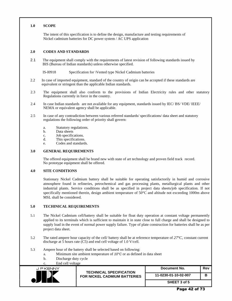
Document No. Rev
11-0230-01-10-02-007 B
TECHNICAL SPECIFICATION
FOR NICKEL CADMIUM BATTERIES SHEET 3 of 5
1.0 SCOPE
The intent of this specification is to define the design, manufacture and testing requirements of Nickel cadmium batteries for DC power system / AC UPS application
2.0 CODES AND STANDARDS 2.1 The equipment shall comply with the requirements of latest revision of following standards issued by BIS (Bureau of Indian standards) unless otherwise specified. IS-I0918 Specification for \Vented type Nickel Cadmium batteries 2.2 In case of imported equipment, standard of the country of origin can be accepted if these standards are equivalent or stringent than the applicable Indian standards. 2.3 The equipment shall also conform to the provisions of Indian Electricity rules and other statutory Regulations currently in force in the country. 2.4 In case Indian standards are not available for any equipment, standards issued by IEC/ BS/ VDE/ IEEE/
NEMA or equivalent agency shall be applicable. 2.5 In case of any contradiction between various referred standards/ specifications/ data sheet and statutory
regulations the following order of priority shall govern: a. Statutory regulations. b. Data sheets c. Job specifications. d. This specifications. e. Codes and standards. 3.0 GENERAL REQUIREMENTS
The offered equipment shall be brand new with state of art technology and proven field track record. No prototype equipment shall be offered.
4.0 SITE CONDITIONS
Stationary Nickel Cadmium battery shall be suitable for operating satisfactorily in humid and corrosive atmosphere found in refineries, petrochemical and gas processing plants, metallurgical plants and other industrial plants. Service conditions shall be as specified in project data sheets/job specification. If not specifically mentioned therein, design ambient temperature of 50°C and altitude not exceeding 1000m above MSL shall be considered.
5.0 TECHINICAL REQUIREMENTS 5.1 The Nickel Cadmium cell/battery shall be suitable for float duty operation at constant voltage permanently
applied to its terminals which is sufficient to maintain it in state close to full charge and shall be designed to supply load in the event of normal power supply failure. Type of plate construction for batteries shall he as per project data sheet.
5.2 The rated ampere hour capacity of the cell/ battery shall be at reference temperature of 27ºC, constant current
discharge at 5 hours rate (C5) and end cell voltage of 1.0 V/cell. 5.3 Ampere hour of the battery shall be selected based on following:
a. Minimum site ambient temperature of 10°C or as defined in data sheet b. Discharge duty cycle c. End cell voltage
Page 42 of 73

Document No. Rev
11-0230-01-10-02-007 B
TECHNICAL SPECIFICATION
FOR NICKEL CADMIUM BATTERIES SHEET 4 of 5
d. Ageing factor of 0.8 e. Design margin if defined in data sheet
5.4 Number of cells and end cell voltage shall be decided by the vendor on the basis of maximum permissible voltage to the load when batteries are float charged while feeding the load and minimum DC system voltage. However the number of cells and end cell voltage shall be as per project data sheet unless other wise specified.
5.5 The battery shall be suitable for being boost charged to fully charged condition from fully discharged
condition within 10 hours unless other wise specified.
5.6 Battery assembly shall be supplied in dry and uncharged. Dry electrolyte and required quantities of electrolyte liquid with 10% extra shall be delivered with the battery in suitable non returnable sealed containers unless otherwise specified.
5.7 Each cell shall have separate container. The cell container shall be of high strength alkali resistant translucent material and designed to withstand mechanical stresses, shocks and vibrations.
5.8 The components such as containers, lids/covers and seals used in manufacture shall meet the Fire, flame and smoke resistance rating as defined in ANSI/UL94 and have an oxygen Index of at least 28 in accordance with ASTM D-2863.
5.9 The terminal posts shall be of nickel plated steel. The terminals shall be suitable for short circuit current and specified discharge current without damage to cell as a result of terminal heating.
5.10 Stationary nickel cadmium cells shall be designed to withstand the mechanical stresses encountered during
normal transportation and handling. 5.11 Flame arrestor shall be mounted on the cell so that all the vented gasses diffuse through the arrestor to the
outside environment. The construction of the arrestor shall be such that hydrogen burning on the external surface of the arrestor shall not propagate back in to the cell to cause explosion.
5.12 The following information shall be permanently marked on the cell.
- Nominal voltage - Name of manufacturer/model reference - Rated capacity in ampere hours (Ah) with End Cell Voltage - Voltage for float operation of 27ºC with tolerance of ±1% - Month and year of manufacture
5.13 Each set of battery shall be supplied with all accessories including but not limited to the following:
a. Battery stand in formation as per enclosed data sheet. Mild steel stand pretreated and epoxy painted / PVC coated.
b. Inter cell, inter row and inter bank connector c. Cell insulator d. Stand insulator e. Cell number plates and fixing pins, Lugs for cable termination as required. f. Other accessories and their quantity as per data sheet. g. Voltmeter(D.C.) to measure individual cell voltage having centre zero with lead. h. Hydrometer, funnel, gloves, spare vent plug
6.0 PERFORMANCE
Nickel Cadmium batteries shall have been type tested to meet the performance requirements for each design and AH rating of cells as per IS-10918.
Page 43 of 73

Document No. Rev
11-0230-01-10-02-007 B
TECHNICAL SPECIFICATION
FOR NICKEL CADMIUM BATTERIES SHEET 5 of 5
7.0 INSPECTION AND TESTING
Batteries shall be subject to inspection by JPK/owner or by an agency authorized by the owner, to assess the progress of work. The manufacturer shall furnish all necessary information concerning the supply to JPK /owner's representative. JPK / owner's representative shall be given free access in the works from time to time for stage wise inspection and progress reporting. Four weeks advance notice shall be given to witness the final routine test and other test as agreed upon. Following routine tests shall be carried out as a minimum as part of acceptance tests for each AH rating of cells/battery. For long duration type tests, type test certificates of identical ampere hour rating shall be furnished. a. Physical examination b. Polarity and absence of short circuit c. Marking and packing d. Verification of dimensions e. Air pressure test f. Test for voltages during discharge g. Test for AH capacity h. Test for charge retention if specified in the data sheet. i. Insulation resistance j Test for impact in variation on ambient temperature Battery duty cycle test to meet the load cycle requirement shall also be performed at site after installation as part of commissioning unless otherwise defined in project data sheet.
8.0 PACKING AND DESPATCH
All the equipment shall be divided into several sections for protection and ease of handling during transportation. The equipment shall be properly packed for transportation by ship/rail or trailer. The equipment shall be wrapped in polythene sheets before being placed in crates/cases to prevent damage to finish. Crates/cases shall have skid bottom for handling. Special notations such as 'Fragile', 'This side up', 'Centre of gravity', 'Weight', 'Owner's particulars', 'PO nos.' etc., shall be clearly marked on the package together with other details as per purchase order. The equipment may be stored outdoors for long periods before installation. The packing shall be completely suitable for outdoor storage in areas with heavy rains/high ambient temperature. * * * * *
Page 44 of 73

GAIL (India) Limited CHAINSA - JHAJJAR PIPELINE PROJECT
CLIENT JOB NO. 110230TECHNICAL SPECIFICATION FOR
BATTERY CHARGER TOTAL SHEETS 14
DOCUMENT NO 11 0230 01 10 02 009
B 18/11/08 ISSUED FOR TENDER SB SP PKS A 14/07/08 ISSUED FOR REVIEW SB SP PKS
REV DATE DESCRIPTION PREP CHK APPR
Page 45 of 73
Document No. Rev
11-0230-01-10-02-009 B
TECHNICAL SPECIFICATION
FOR BATTERY CHARGER SHEET 2 of 14
CONTENTS
1.0 SCOPE 2.0 CODES AND STANDERDS 3.0 GENERAL REQUIREMENTS 4.0 SITE CONDITIONS 5.0 TECHINICAL REQUIREMENTS 6.0 INSPECTION, TESTING AND ACCEPTANCE 7.0 PACKING AND DESPATCH
Page 46 of 73
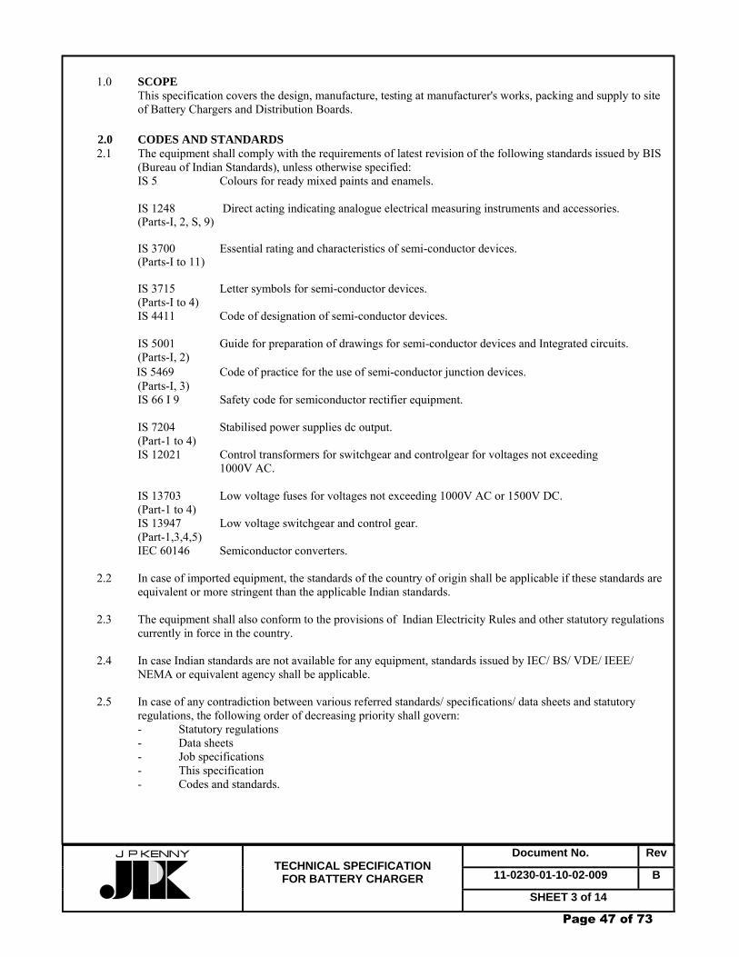
Document No. Rev
11-0230-01-10-02-009 B
TECHNICAL SPECIFICATION
FOR BATTERY CHARGER SHEET 3 of 14
1.0 SCOPE This specification covers the design, manufacture, testing at manufacturer's works, packing and supply to site
of Battery Chargers and Distribution Boards. 2.0 CODES AND STANDARDS 2.1 The equipment shall comply with the requirements of latest revision of the following standards issued by BIS
(Bureau of Indian Standards), unless otherwise specified: IS 5 Colours for ready mixed paints and enamels.
IS 1248 Direct acting indicating analogue electrical measuring instruments and accessories. (Parts-I, 2, S, 9) IS 3700 Essential rating and characteristics of semi-conductor devices. (Parts-I to 11) IS 3715 Letter symbols for semi-conductor devices. (Parts-I to 4)
IS 4411 Code of designation of semi-conductor devices. IS 5001 Guide for preparation of drawings for semi-conductor devices and Integrated circuits. (Parts-I, 2) IS 5469 Code of practice for the use of semi-conductor junction devices. (Parts-I, 3) IS 66 I 9 Safety code for semiconductor rectifier equipment. IS 7204 Stabilised power supplies dc output. (Part-1 to 4) IS 12021 Control transformers for switchgear and controlgear for voltages not exceeding 1000V AC. IS 13703 Low voltage fuses for voltages not exceeding 1000V AC or 1500V DC. (Part-1 to 4) IS 13947 Low voltage switchgear and control gear. (Part-1,3,4,5) IEC 60146 Semiconductor converters. 2.2 In case of imported equipment, the standards of the country of origin shall be applicable if these standards are
equivalent or more stringent than the applicable Indian standards. 2.3 The equipment shall also conform to the provisions of Indian Electricity Rules and other statutory regulations
currently in force in the country. 2.4 In case Indian standards are not available for any equipment, standards issued by IEC/ BS/ VDE/ IEEE/
NEMA or equivalent agency shall be applicable. 2.5 In case of any contradiction between various referred standards/ specifications/ data sheets and statutory
regulations, the following order of decreasing priority shall govern: - Statutory regulations - Data sheets - Job specifications - This specification - Codes and standards.
Page 47 of 73

Document No. Rev
11-0230-01-10-02-009 B
TECHNICAL SPECIFICATION
FOR BATTERY CHARGER SHEET 4 of 14
3.0 GENERAL REQUIREMENTS 3.1 The offered equipment shall be brand new with state of the art technology and a proven field track record. No
prototype equipment shall be offered. 3.2 Vendor shall ensure availability of spare parts and maintenance support services for the offered equipment for
at least 15 years from the date of supply. 3.3 Vendor shall give a notice of at least one year to the end user of equipment and JPK before phasing out the
product/ spares to enable the end user to place order for spares and services. 3.4 The Battery Charger system shall be an integrated system comprising of static rectifiers, DC Distribution
Board, isolating and protection devices and all other equipment! accessories required for completeness of the system whether specifically mentioned herein or not, but necessary for completeness and satisfactory performance of the system. The Battery Charger equipment shall be properly coordinated with the selected Battery to ensure complete compatibility.
3.5 All equipment and components shall be of excellent quality and reliability for providing secure DC power
required for vital equipment performance, controlling, monitoring and safeguarding functions in continuously operating process units and utility installations of petroleum refineries, petrochemical and gas processing facilities and other industrial plants. Components shall be capable of withstanding the thermal and dynamic stresses resulting from internal and external short circuits and circuit switching operations etc. The design of the equipment shall be such as to minimize the risk of short circuits and shall ensure personnel and operational safety.
3.6 The vendor shall be responsible for design, engineering and manufacturing of the complete system to fully
meet the intent and requirements of this specification and attached data sheets. 3.7 The Battery shall meet the requirements of data sheets and specifications attached with the Material
Requisition! Bid document. 4.0 SITE CONDITIONS
The Battery Chargers shall be suitable for installation and satisfactory operation in a pressurised or non-pressurised substation with restricted natural air ventilation in a tropical, humid and corrosive atmosphere. The Battery Chargers shall be designed to operate under site conditions as specified in the data sheet. If not specifically mentioned therein, design ambient temperature of 40º C and altitude not exceeding 1000 m above MSL shall be considered for all equipment.
5.0 TECHNICAL REQUIRENTS 5.1 Input Power Supply 5.1.1 The Battery Chargers shall be suitable for input power supply as defined in the data sheet. If not specified
therein, they shall be suitable for the following input power supply: Voltage : 415V ± 10% Frequency : 50 Hz ± 5% Wherever phase selector has been provided, voltage may be selected accordingly.
In addition to the above variations, the input voltage may be subject to transient variations comprising of voltage dips up to 20% of normal voltage during motor start-up, voltage interruptions during short circuits as well as frequency variations due to large motor start-up. The Battery Chargers shall operate satisfactorily with a total harmonic distortion of up to 5 % in the input power supply.
Page 48 of 73

Document No. Rev
11-0230-01-10-02-009 B
TECHNICAL SPECIFICATION
FOR BATTERY CHARGER SHEET 5 of 14
The Battery Chargers shall also be designed to operate satisfactorily while drawing input power from an emergency diesel generator set.
5.1.2 The incoming power supply to the Battery Charger system shall be provided by 2 independent feeders. One feeder shall supply power to each rectifier.
5.2 Battery Charger 5.2.1 Design Basis 5.2.1.1 The Battery Charger system shall have two chargers(Charger-l & Charger-2). Both chargers shall be of
identical design and rating. The battery to be connected to the chargers shall be of Nickel Cadmium/ flooded electrolyte Lead Acid/ VRLA type as indicated in the data sheet. Battery Chargers for flooded Lead Acid and Nickel Cadmium batteries shall be sized to provide quick charging of the battery within a duration of 10 hours, unless specified otherwise. Battery Chargers for VRLA battery shall be sized to provide quick charging of the battery up to 90 % of rated Amperehours within a duration of 24 hours and to 100% within 4 days. Each charger shall be sized for the most stringent of the following duty conditions, whichever is higher:
a. Offline quick charging of the battery assembly. The charger shall be sized as under: Charger rating in Amps. = 0.14 Ah(C10) of battery (for Lead Acid battery) = 0.2 Ah(C10) of battery (for Lead Acid battery) = 0.2 Ah(C5) of battery (for Nickel Cadmium battery)
b. Online float charging of the battery assembly while feeding the complete DC load. The charger shall be sized as under:
Charger rating in Amps. = 1.15 x Average DC load + float charging current
(Average DC load = Area under the battery duty cycle/ battery duty cycle duration).
c. Initial charging of the uncharged battery assembly to fully charged condition. 5.2.1.2 Each charger shall have a 3 phase full wave, controlled rectifier bridge with protective devices. 5.2.1.3 Independent current limits shall be provided for charger load current and battery charging current. Subsequent
to a discharge cycle and completion of quick charging, when battery is connected to charger under float mode, the battery current shall be monitored, controlled and limited to set value automatically irrespective of the value of load current. Fast acting semi-conductor fuses shall be provided for protection against internal short circuits. In case of external short circuits, the chargers shall be protected by rapid shutdown of the semi-conducting power devices. The high speed semi-conductor fuses used for rectifier protection shall be complete with trip indication.
5.2.1.4 Filter circuits consisting of smoothing choke and condenser, complete with protection to limit the ripple content at the output, shall be provided.
5.2.1.5 Silicon blocking diodes shall be provided in the charger output circuit to prevent back-feed from battery into the charger and filters. 5.2.1.6 Protection against reverse battery connection and DC earth fault relay for earth leakage protection shall be Provided. 5.2.1.7 Silicon blocking diodes (min. 4 nos.) connected to 80% tap of the battery bank shall be provided to maintain continuity in the DC supply to the load. 5.2.1.8 Internal cooling of the charger unit shall preferably be by natural ventilation. If forced air cooling is necessary,
a redundant air cooling fan shall be provided for each service. The charger components shall be capable of delivering their rated output with one forced air cooling fan out of service. Under this condition, maximum continuous temperature of components shall not exceed the permissible limits. In case of chargers with forced cooling, loss of ventilation alarm! trip with override facilities shall be provided.
Page 49 of 73
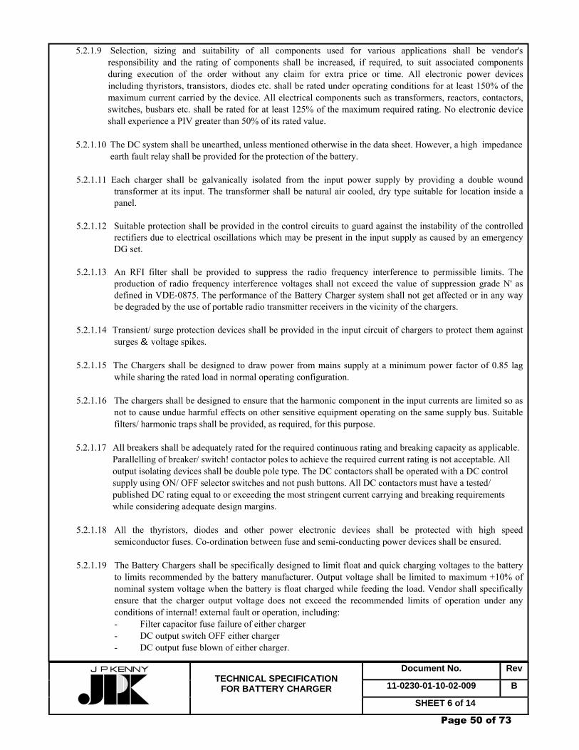
Document No. Rev
11-0230-01-10-02-009 B
TECHNICAL SPECIFICATION
FOR BATTERY CHARGER SHEET 6 of 14
5.2.1.9 Selection, sizing and suitability of all components used for various applications shall be vendor's responsibility and the rating of components shall be increased, if required, to suit associated components during execution of the order without any claim for extra price or time. All electronic power devices including thyristors, transistors, diodes etc. shall be rated under operating conditions for at least 150% of the maximum current carried by the device. All electrical components such as transformers, reactors, contactors, switches, busbars etc. shall be rated for at least 125% of the maximum required rating. No electronic device shall experience a PIV greater than 50% of its rated value.
5.2.1.10 The DC system shall be unearthed, unless mentioned otherwise in the data sheet. However, a high impedance earth fault relay shall be provided for the protection of the battery. 5.2.1.11 Each charger shall be galvanically isolated from the input power supply by providing a double wound
transformer at its input. The transformer shall be natural air cooled, dry type suitable for location inside a panel.
5.2.1.12 Suitable protection shall be provided in the control circuits to guard against the instability of the controlled
rectifiers due to electrical oscillations which may be present in the input supply as caused by an emergency DG set.
5.2.1.13 An RFI filter shall be provided to suppress the radio frequency interference to permissible limits. The
production of radio frequency interference voltages shall not exceed the value of suppression grade N' as defined in VDE-0875. The performance of the Battery Charger system shall not get affected or in any way be degraded by the use of portable radio transmitter receivers in the vicinity of the chargers.
5.2.1.14 Transient/ surge protection devices shall be provided in the input circuit of chargers to protect them against
surges & voltage spikes. 5.2.1.15 The Chargers shall be designed to draw power from mains supply at a minimum power factor of 0.85 lag
while sharing the rated load in normal operating configuration. 5.2.1.16 The chargers shall be designed to ensure that the harmonic component in the input currents are limited so as
not to cause undue harmful effects on other sensitive equipment operating on the same supply bus. Suitable filters/ harmonic traps shall be provided, as required, for this purpose.
5.2.1.17 All breakers shall be adequately rated for the required continuous rating and breaking capacity as applicable.
Parallelling of breaker/ switch! contactor poles to achieve the required current rating is not acceptable. All output isolating devices shall be double pole type. The DC contactors shall be operated with a DC control supply using ON/ OFF selector switches and not push buttons. All DC contactors must have a tested/ published DC rating equal to or exceeding the most stringent current carrying and breaking requirements while considering adequate design margins.
5.2.1.18 All the thyristors, diodes and other power electronic devices shall be protected with high speed semiconductor fuses. Co-ordination between fuse and semi-conducting power devices shall be ensured.
5.2.1.19 The Battery Chargers shall be specifically designed to limit float and quick charging voltages to the battery
to limits recommended by the battery manufacturer. Output voltage shall be limited to maximum +10% of nominal system voltage when the battery is float charged while feeding the load. Vendor shall specifically ensure that the charger output voltage does not exceed the recommended limits of operation under any conditions of internal! external fault or operation, including:
- Filter capacitor fuse failure of either charger - DC output switch OFF either charger - DC output fuse blown of either charger.
Page 50 of 73

Document No. Rev
11-0230-01-10-02-009 B
TECHNICAL SPECIFICATION
FOR BATTERY CHARGER SHEET 7 of 14
Other specific current/ voltage limits during normal charging/ operation of the chargers shall also be incorporated in the design of the chargers.
5.2.2 Operation and Performance 5.2.2.1 Operation a. Normal operation requires that the battery assembly shall be float charged simultaneously by both
Chargers-l & 2 while feeding the DC load, the chargers thus operating in parallel and equally sharing the total load.
b. However in case of failure of either of the chargers, the other charger shall float charge the battery while feeding the complete DC load. Faulty charger shall automatically get disconnected from the healthy system.
c. In case of AC mains failure, the battery shall continue to supply the load. d. The process of changeover from float to quick charging and reverting from quick to float charging
shall be selectable in Automatic or Manual mode by means of an Auto/ Manual selector switch. In Automatic mode, the changeover from float to quick charging shall be initiated through a current sensor, set at a preset value. Similarly, the changeover from quick to float charging shall also be automatic based on current sensing. In Manual mode, both changeovers from float to quick charging and from quick to float charging shall be performed manually using push buttons. When quick charging mode is selected, the battery charger shall initially charge the battery under constant current mode followed by constant voltage (finishing charging) mode or as per the battery manufacturer's recommendation. Changeover from constant current to constant voltage (finishing charging) mode shall be fully automatic. A backup synchronous or digital timer shall also be provided for initiating the changeover to float mode by default after a preset time period. The timer range shall be 0 to 24 hours or the nearest available as per manufacturer's standard range.
e. In the event of failure of the charger feeding the load, when battery is being quick charged by the
other charger, continuity in DC supply shall be maintained from the battery to the load through 80 % tap of the battery bank followed by full battery supplying the load through contactor C-2 .
f. Interlock shall be provided to ensure that when either of the chargers is selected in quick charging
mode, it will be disconnected from both the DC load and the other charger operating under float charging mode.
g. The chargers shall have facility for manual mode of operation in the event of failure of controller under closed loop control The selection shall be done through Auto/ Manual selector switch. h. Energisation of contactor for DC critical lighting shall be initiated by means of an AC mains failure
relay complete with Auto/ Manual selector switch, On/ Off push buttons etc. i. Facility for Initial charging of the uncharged battery shall also be provided.
5.2.2.2 Performance
a. Both chargers shall be of solid state design, constant voltage and current limit type. The output
voltage shall be stabilised to within ± 1 % of set value in float charging mode for mains steady state voltage and frequency variation of ±10% and ±5% respectively, and load variation of 10 to 100 % at any temperature up to the design ambient temperature specified in the data sheet. However, the
Page 51 of 73

Document No. Rev
11-0230-01-10-02-009 B
TECHNICAL SPECIFICATION
FOR BATTERY CHARGER SHEET 8 of 14
variation in output voltage can be up to ±2% for chargers with rated output voltage up to 24V. b. Under constant current boost charging condition, the DC output current shall be maintained within ±2
% of set value.
The output voltage dynamic response of the charger unit with battery disconnected shall not vary more than ± 10 % of nominal output voltage in the event of step load of up to 50 % of the rated output. The output voltage shall be restored to a value within the steady state limits within 250 msec. Voltage feedback shall generally be derived from charger output while current feedback from the DC ammeter.
c. The maximum allowable RMS ripple voltage, with battery disconnected, shall be equal to or less than 2 % of the nominal output voltage.
d. The maximum noise level from the chargers measured at 1 metre distance in any position, at any load
between 0- 100% with all normal cooling fans running shall not exceed 75 dB(A) . 5.2.2.3 Controls Controls shall include but not be limited to the following: a. ON / OFF control switch for AC supply to charger (push buttons are not acceptable) b. Push buttons for float/ quick charging mode selection c. Potentiometers under float mode for voltage and current adjustment d. Potentiometers under quick mode for voltage and current adjustment e. Auto/ Manual selector switch to select mode of operation f. Others as required. 5.2.2.4 Panel Metering and Indication These shall include but are not limited to the following: a. Meters (1) Charger-1 - AC input Voltmeter with selector switch - AC input Ammeter with selector switch - DC output Voltmeter - DC output Ammeter - DC Voltmeter with selector switch (battery voltage) - DC Ammeter (battery) - DC Earth Leakage Ammeter (mA). (2) Charger-2 - AC input Voltmeter with selector switch - AC input Ammeter with selector switch - DC output Voltmeter - DC output Ammeter (3) DC Distribution Board - DC output Voltmeter - DC output Ammeter b. Lamps (1) Chargers-1 & 2 - AC power ON (1 lamp for each phase) - Float charger ON - Quick charger ON
Page 52 of 73
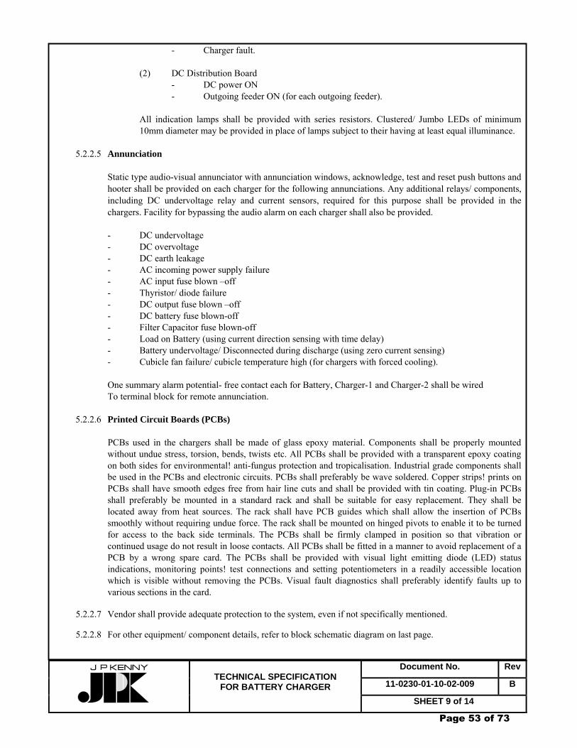
Document No. Rev
11-0230-01-10-02-009 B
TECHNICAL SPECIFICATION
FOR BATTERY CHARGER SHEET 9 of 14
- Charger fault. (2) DC Distribution Board - DC power ON - Outgoing feeder ON (for each outgoing feeder).
All indication lamps shall be provided with series resistors. Clustered/ Jumbo LEDs of minimum 10mm diameter may be provided in place of lamps subject to their having at least equal illuminance.
5.2.2.5 Annunciation
Static type audio-visual annunciator with annunciation windows, acknowledge, test and reset push buttons and hooter shall be provided on each charger for the following annunciations. Any additional relays/ components, including DC undervoltage relay and current sensors, required for this purpose shall be provided in the chargers. Facility for bypassing the audio alarm on each charger shall also be provided.
- DC undervoltage - DC overvoltage - DC earth leakage - AC incoming power supply failure - AC input fuse blown –off - Thyristor/ diode failure - DC output fuse blown –off - DC battery fuse blown-off - Filter Capacitor fuse blown-off - Load on Battery (using current direction sensing with time delay) - Battery undervoltage/ Disconnected during discharge (using zero current sensing) - Cubicle fan failure/ cubicle temperature high (for chargers with forced cooling). One summary alarm potential- free contact each for Battery, Charger-1 and Charger-2 shall be wired To terminal block for remote annunciation. 5.2.2.6 Printed Circuit Boards (PCBs)
PCBs used in the chargers shall be made of glass epoxy material. Components shall be properly mounted without undue stress, torsion, bends, twists etc. All PCBs shall be provided with a transparent epoxy coating on both sides for environmental! anti-fungus protection and tropicalisation. Industrial grade components shall be used in the PCBs and electronic circuits. PCBs shall preferably be wave soldered. Copper strips! prints on PCBs shall have smooth edges free from hair line cuts and shall be provided with tin coating. Plug-in PCBs shall preferably be mounted in a standard rack and shall be suitable for easy replacement. They shall be located away from heat sources. The rack shall have PCB guides which shall allow the insertion of PCBs smoothly without requiring undue force. The rack shall be mounted on hinged pivots to enable it to be turned for access to the back side terminals. The PCBs shall be firmly clamped in position so that vibration or continued usage do not result in loose contacts. All PCBs shall be fitted in a manner to avoid replacement of a PCB by a wrong spare card. The PCBs shall be provided with visual light emitting diode (LED) status indications, monitoring points! test connections and setting potentiometers in a readily accessible location which is visible without removing the PCBs. Visual fault diagnostics shall preferably identify faults up to various sections in the card.
5.2.2.7 Vendor shall provide adequate protection to the system, even if not specifically mentioned. 5.2.2.8 For other equipment/ component details, refer to block schematic diagram on last page.
Page 53 of 73

Document No. Rev
11-0230-01-10-02-009 B
TECHNICAL SPECIFICATION
FOR BATTERY CHARGER SHEET 10 of 14
5.3 Construction of Chargers/ Distribution Board 5.3.1 Each Battery Charger and DC distribution board shall be housed in a separate free standing cubicle. All panels
shall be of the same height so as to form a panel lineup which shall have good aesthetic appearance. Chargers-l & 2 shall be installed side by side whereas DCDB may be located separately and interconnected to the charger through cables. The DC DB shall accommodate outgoing feeders as specified in the data sheet. Each panel shall be provided with an 11 W CFL light with a door operated switch and a thermostatically controlled MCB protected space heater.
Unless specified otherwise in the data sheet, the DCDB shall be compartmentalised with each outgoing feeder
housed in a separate compartment. Cable alley of minimum 200mm width with suitable supports shall be provided for the termination of cables for each vertical arrangement of outgoing feeders in DCDB.
5.3.2 The Chargers, DCDB and Cell Booster enclosures shall be fabricated from structural/ CRCA sheet steel. The
frames shall be fabricated by using minimum 2mm thick CRCA sheet steel while the doors and covers shall be made from minimum 1.6 mm thick CRCA sheet steel. Wherever required, suitable stiffeners shall be provided. The panels shall be provided with suitable louvres for ventilation backed by wire mesh. They must be suitable for use in a tropical climate. Hinged doors shall be provided at the front and back as required. Interpanel sheet steel barriers shall be provided.
5.3.3 The Boost charger panels shall be provided with minimum IP-65 degree of ingress protection and Redundant
type battery charger & DC distribution board shall be provided with minimum IP-31 degree of ingress protection as per 1S-13947 (Part-I).
5.3.4 Bus bars shall be colour coded and live parts shall be shrouded to ensure complete safety to personnel
intending routine inspection by opening the panel doors. All the equipment inside the panel and on the doors shall have suitable nameplates and device tag numbers as per the schematic diagram. All wires shall be ferruled and terminals shall be numbered.
5.3.5 The DCDB incomer and main busbars shall be rated based on the maximum load current considering an
additional 10% design margin for contingencies. The rating shall be selected from standard available ratings and shall be adequate for the expected short circuit current. The busbar voltage shall be higher than the recommended boost voltage for the system. The insulation for all equipment where provided shall be heat resistant, moisture proof and tropicalised.
5.3.6 All power and control switches shall be rotary/ cam operated type. All power switches shall be air insulated load break type. Vendor shall ensure that all equipment/ components such as incomer switches, outgoing DC switches, MCCBs, push buttons, indicating lamps, charger mode selector switches, voltage control switches, annunciator windows etc. are suitably located on the charger and distribution board door such that they can be operated without opening the front door. Power switches shall be provided with a door interlock. In case of difficulty in installation on the charger front panel door, the AC incoming power switches, DC outgoing switches and MCCBs may be installed within the panel provided that they are operable after opening the front panel door. However, all other selector/ control switches, push buttons, indicating lamps, annunciators, meters etc. shall necessarily be installed on the front panel door as specified above.
5.3.7 All instruments shall be switchboard type, back connected and 72 x 72 mm square size. Accuracy class of all
meters shall be 1%. Digital meters capable of displaying different parameters can be considered subject to Owner's/ JPK's approval. Analogue instrument scales shall have a red mark indicating maximum permissible operating rating.
5.3.8 All fuses shall be link type and shall be located inside the panel. 5.3.9 All power and control wiring connections within the panels shall be carried out with 660V grade, PVC
insulated, BIS marked wires having stranded copper conductors. However, copper strip connections shall preferably be used for currents exceeding l00 A. Wires of 1.5 mm2 size shall normally be used for control
Page 54 of 73

Document No. Rev
11-0230-01-10-02-009 B
TECHNICAL SPECIFICATION
FOR BATTERY CHARGER SHEET 11 of 14
circuits with fuse rating of 10 Amps. or less. For control circuits with fuse of 16 Amps. or more, 2.5 mm2 size wire shall be used. Control wiring for electronic circuits/ components shall be through flat ribbon cable or copper wire of minimum 0.5mm diameter. All control wiring shall be enclosed in PVC channels or otherwise neatly bunched together. Each wire sball be suitably identified at both ends by PVC ferrules. Ferrulling of wires shall be as per relevant IS.
5.3.10 For all cabling external to panels, power cables shall be with aluminum/ copper conductors and control cables
shall be with copper conductors. All cable connections shall be from the bottom of the panel, unless specified otherwise in the data sheet. Removable bolted undrilled gland plates shall be provided along with single compression type nickel plated brass cable glands for all external cable connections. Clamp type terminals shall be used for connection of wires up to 10 mm2. Bolted type terminals suitable for cable lugs shall be provided for wire sizes above this. Separate test terminals sball be provided for measuring and testing the equipment to check performance. All panels shall be supplied complete with tinned copper cable termination lugs of required size.
5.3.11 All potential free metallic parts shall be earthed using soft drawn copper conductor wire. A suitably sized
earth bus shall be provided at the bottom of the panels running through the panel lineup with provision for earth connections at both ends to owner's main earth grid. The minimum size of earth bus shall be 25 x 6 mm2 copper (or equivalent aluminium). All potential free metallic parts of equipment shall be suitably earthed to ensure safety.
5.3.12 The maximum height of the operating handles/ switches shall not exceed 1800 mm and the minimum height
shall not be below 300 mm. 5.3.13 All components/ devices/ feeders shall be provided with screwed nameplates. Nameplates shall be 3 ply
white-black-white 2 colour laminated plastic type. Lettering shall be of minimum 6 mm height and edges shall be bevelled at 45°.
5.3.14 The sheet steel used for fabrication shall be thoroughly cleaned and degreased to remove mill scale, rust,
grease and dirt. Fabricated structures shall be pickled and then rinsed to remove any trace of acid. The under-surface shall be prepared by applying a coat of phosphate paint and a coat of zinc oxide/ phosphate primer. The under-surface shall be free from all imperfections before undertaking the finishing coat. After preparation of the under-surface, the panels shall be either spray painted with two coats of epoxy paint or epoxy powder coated to a uniform thickness suitable for rugged industrial use.
Colour of final paint shall be shade 631 as per IS 5, unless specified otherwise. The finished panels shall be dried in stoving ovens in dust free atmosphere. Panel finish shall be free from imperfections like pinholes, orange peels, run off paint etc. All unpainted steel parts shall be cadmium plated or suitably treated to prevent rust corrosion.
5.4 Cell Booster
Cell booster shall be suitable for charging one to six cells within the time duration specified at CI.5. 2 .1. 1. It shall be suitable for charging not only new cells before being introduced to the battery bank but also for any treatment to be given to individual weak cells. Cell booster shall be suitable for 240 V ± 10%, 50 Hz ± 5 % SPN input power supply. Cell booster output voltage shall be in the range of 0-18V and 0-12V for Lead Acid and Nickel Cadmium batteries respectively. Cell booster shall be sized as under: For Lead Acid battery = 0.14 x AH (C10) of cell For VRLA battery = 0.2 x AH (C10) of cell For Ni-Cd battery = 0.2 x AH (C5) of cell
Page 55 of 73

Document No. Rev
11-0230-01-10-02-009 B
TECHNICAL SPECIFICATION
FOR BATTERY CHARGER SHEET 12 of 14
Cell booster shall have a heavy duty switch fuse or MCCB on both AC incomer and DC output sides, along with AC voltmeter, DC ammeter, DC voltmeter and indicating lamps for AC/ DC power ON. The output voltage and current of cell booster shall be manually controlled using a suitably rated variac or a full wave controlled rectifier bridge. Suitable interlock shall be provided so as to ensure that the variac./ controlled rectifier is at its minimum position while switching on the cell booster. Cell booster shall be portable type with wheels. Each cell booster shall be supplied with 5 m long flexible copper conductor, PVC insulated braided cables for both AC incoming power supply and DC output connection to the battery. An industrial type 3 pin 15A plug shall be provided on AC incoming cable end and lugs shall be provided on DC outgoing cable end.
5.5 Reliability
All necessary care shall be taken in selection, design, manufacture, testing and commissioning of the equipment for ensuring high system reliability. The following design considerations shall be taken into account to ensure maximum availability of the system:
5.5.1 There shall be no common device between the two units, the failure of which could cause shutdown of more than one charger. 5.5.2 It shall be possible to attend to any individual power circuit for maintenance without affecting the total
DC supply. 5.5.3 Series-parallel combination of smaller devices to achieve specified rating shall not be acceptable. 5.5.4 All the components used shall be time tested and standardized. Vendor shall state the safety factors used in
selecting such items as semi-conductors, electrolytic capacitors, transformers etc. 6.0 INSPECTION, TESTING AND ACCEPTANCE 6.1 During fabrication, the equipment shall be subjected to inspection by JPK / Owner or by an agency authorised
by the Owner. Manufacturer shall furnish all necessary information concerning the supply to JPK's /Owner's inspector. Tests shall be carried out at manufacturer's works under his care and expense.
6.2 Each Battery Charger/ DCDB / Cell Booster shall be tested in accordance with applicable standards. The
following acceptance tests shall be performed on each Battery Charger and DCDB as a minimum. Detailed test schedule and procedures shall be formulated by the vendor and submitted for JPK's/ Owner's approval. Vendor shall indicate the maximum allowable tolerance against each test parameter in line with applicable standards. All tests shall be witnessed by owner or his authorised representative and 4 weeks prior notice shall be given before the date of commencement of tests. In case the equipment fails to meet any requirements of the specifications, necessary modifications/ corrections shall be made by the vendor to ensure compliance to the specifications, and the equipment shall be retested before acceptance. Test certificates in triplicate indicating the test results shall be submitted to owner.
6.2.1 Insulation Tests Insulation tests shall be performed as per IEC 60146-1-1. The insulation tests shall be carried out using an AC power frequency voltage or a DC voltage at the choice
of the manufacturer. In the case of AC power frequency voltage test, the test voltage at the frequency available in the test facility or at the rated frequency, but not exceeding 100 Hz, shall be increased to the full value shown in the following table in not less than 10 seconds continuously or in maximum steps of 0.05 p.u. of the full value starting at a maximum of 0.5 p.u. The unit on test shall withstand the specified voltage for 1 minute.
Page 56 of 73

Document No. Rev
11-0230-01-10-02-009 B
TECHNICAL SPECIFICATION
FOR BATTERY CHARGER SHEET 13 of 14
In case DC voltage is used for the test, the value of DC voltage shall be equal to the crest value of the test voltage specified in the table.
Vp/ √2
(Vp is the highest crest voltage to be expected Between any pair of terminals
Test Voltage (AC RMS Value)
≤ 60 V 500 V ≤ 60 V 1000 V ≤ 60 V 1500 V ≤ 60 V 2000 V
6.2.2 Printed Circuit Boards
PCBs and other electronic circuits shall undergo a burn-in test for 96 hours at 50°C at a voltage varied between the maximum and minimum supply voltage. In case of failure of any component during testing, the tests shall be repeated after replacement of the faulty component.
6.2.3 Heat Run Test
Prior to execution of functional tests, each of the two chargers of each Battery Charger set shall be subjected to a Heat Run test performed at rated load and voltage for a period not less than 8 hours. The other charger of the set shall be energized under zero load current condition throughout the test period. The temperature of electronic power devices shall be measured and the device junction temperature shall be calculated. The calculated value shall be at least 10-20°C lesser than the maximum rated junction temperature of the device with proper ambient temperature correction applied.
6.2.4 Functional Tests Functional tests shall be performed on each charger. If during execution of functional tests, an electronic component of the charger is required to be replaced, e.g. due to charger malfunction or failure of the unit to fulfill the performance requirements of the specification, then the heat run test shall be repeated at rated current following which functional tests shall be carried out.
6.2.4.1 Charger Testing at Constant Output Voltage
Measurements shall be carried out in the float charging mode and in the quick charging mode. In each mode, measurements shall be carried out at nominal AC input voltage and at zero, 50% and 100% of rated output current. Measurements at 100% rated load current shall be repeated at 90% and 110% of nominal AC supply voltage. Measurements shall include input AC phase voltage, frequency, current and power and DC output voltage, current and output voltage ripple.
6.2.4.2 Charger Testing at Constant Output Current Limit
Measurements shall be carried out both in the float charging and quick charging mode. In each mode, measurements shall be carried out when the charger is operating under DC current limiting conditions with DC output voltage between zero and set value corresponding to constant voltage operation. Measurements shall include DC output voltage and current.
6.2.4.3 Auxiliary Equipment and Control Circuit Tests
The correct functioning of all measuring instruments, alarms, indications, protections and controls mentioned in the specification shall be verified.
Page 57 of 73

Document No. Rev
11-0230-01-10-02-009 B
TECHNICAL SPECIFICATION
FOR BATTERY CHARGER SHEET 14 of 14
6.2.4.4 Parallel Operation
Parallel operation of both chargers, sharing of the load and automatic isolation of faulty charger shall be checked.
6.2.4.5 Charger Efficiency
This shall be determined by measurement of the active power input and output at 50%, 75 % and 100% load.
6.2.4.6 Audible Noise Test
Audible noise shall be measured around each charger at 1 meter distance in at least 4 to 5 positions and its value shall be within the permissible limits.
6.3 Site Acceptance Test
The Battery Chargers, DCDB and Cell Boosters shall be tested at site along with the battery. Vendor shall furnish a Site Acceptance Test (SAT) procedure for owner's approval and all tests shall be performed as per the approved SAT procedure.
7.0 PACKING AND DESPATCH
All the equipment shall be divided into several sections for protection and ease of handling during transportation. The equipment shall be properly packed for transportation by ship/ rail or trailer. It shall be wrapped in polythene sheets before being placed in crates/ cases to prevent damage to finish. The crates/ cases shall have skid bottoms for handling. Special notations such as 'Fragile', 'This side up', 'Center of gravity', 'Weight', 'Owner's particulars', 'PO no.' etc., shall be clearly and indelibly marked on the packages together with other details as per purchase order. The equipment may be stored outdoors for long periods before installation. The packing shall be completely suitable for outdoor storage in areas with heavy rains and high ambient temperature unless otherwise agreed.
* * * * *
Page 58 of 73

GAIL (India) Limited
CHAINSA - JHAJJAR PIPELINE PROJECT
CLIENT JOB NO. 110230TECHNICAL DATA SHEET FOR
SOLAR SYSTEM TOTAL SHEETS 06
DOCUMENT NO 11 0230 01 10 03 002
B 26/08/08 ISSUED FOR TENDER SB SP PKS A 08/07/08 ISSUED FOR REVIEW SB SP PKS
REV DATE DESCRIPTION PREP CHK APPR
Page 59 of 73
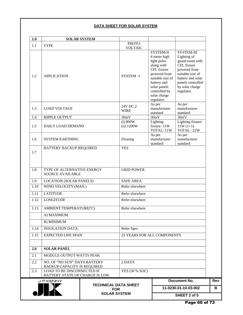
Document No. Rev
11-0230-01-10-03-002 B
TECHNICAL DATA SHEET
FOR SOLAR SYSTEM SHEET 2 of 5
DATA SHEET FOR SOLAR SYSTEM
1.0 SOLAR SYSTEM
1.1 TYPE PHOTO VOLTAIC
1.2 APPLICATION SYSTEM -1
SYSTEM-II 4 meter high light poles along with CFL fixture powered from suitable size of battery and solar panels controlled by solar charge regulator.
SYSTEM-III Lighting of guard room with CFL fixture powered from suitable size of battery and solar panels controlled by solar charge regulator.
1.3 LOAD VOLTAGE 24V DC,2 WIRE
As per manufacturer standard
As per manufacturer standard
1.4 RIPPLE OUTPUT 30mV 30mV 30mV
1.5 DAILY LOAD DEMAND (i) 800W (ii) 1200W
Lighting fixture: 11W TOTAL: 11W
Lighting fixture: 11W (1+1) TOTAL : 22W
1.6 SYSTEM EARTHING Floating As per manufacturer standard
As per manufacturer standard
1.7
BATTERY BACKUP REQUIRED YES
1.8 TYPE OF ALTERNATIVE ENERGY SOURCE AVAILABLE
GRID POWER
1.9 LOCATION (SOLAR PANELS) SAFE AREA 1.10 WIND VELOCITY (MAX.) Refer elsewhere
1.11 LATITUDE Refer elsewhere
1.12 LONGITUDE Refer elsewhere
1.13 AMBIENT TEMPERATURE(ºC) Refer elsewhere
A) MAXIMUM
B) MINIMUM
1.14 INSOLATION DATA Refer Spec.
1.15 EXPECTED LIFE SPAN 25 YEARS FOR ALL COMPONENTS
2.0 SOLAR PANEL
2.1 MODULE OUTPUT WATTS PEAK
2.2 NO. OF “NO SUN” DAYS BATTERY BACKUP CAPACITY IS REQUIRED
2 DAYS
2.3 LOAD TO BE DISCONNECTED IF BATTERY STATE OF CHARGE IS LOW
YES (30 % SOC)
Page 60 of 73

Document No. Rev
11-0230-01-10-03-002 B
TECHNICAL DATA SHEET
FOR SOLAR SYSTEM SHEET 3 of 5
(INDICATE SOC%)
2.4 PV ARRAY MOUNTING CONSIDERATIONS
2.5 CLEAR SPACE REQUIRED FOR MOUNTING THE SOLAR PANEL ARRAY
2.6 SYSTEM DOWNTIME CONSIDERATIONS (TO DETERMINE SYSTEM SAFETY FACTORS)
2.7 SOLAR MODULE FRAMING MATERIAL
2.8 MODULE DIMENSIONS /WEIGHT
2.9 JUNCTION BOX MATERIAL OF SOLAR PANEL
2.10 MATERIAL OF BIRD SPIKES
2.11 NO. OF BIRD SPIKES PER MODULE
2.12 NO. OF BY-PASS DIODES PER MODULE
2.13 MAKE AND TYPE OF BY-PASS DIODES
2.14 NO. OF SOLAR CELLS PER MODULE
2.15 SOLAR CELL MANUFACTURER’S TYPE REF. NO.
2.16 MAKE OF SOLAR MODULES
2.17 COUNTRY OF ORIGIN
2.18 WEIGHT OF SOLAR MODULE
2.19 MAX. TEMPERATURE RISE OF SOLAR CELLS UNDER SEVERE WORKING CONDITION OVER MAX. AMBIENT TEMPERATURE
2.20 NOMINAL VOLTAGE OF SOLAR ARRAY
2.21 ANNUAL DEFICIT OF CAPACITY (AH) FROM SOLAR ARRAY
2.22 WEIGHT OF SOLAR ARRAY
2.23 DIMENSION OF SOLAR ARRAY JUNCTION BOX
2.24 MATERIAL OF SOLAR ARRAY JUNCTION BOX
2.25 DEGREE OF PROTECTION OF SOLAR ARRAY JB
2.26 NO. OF SOLAR PANELS
3.0 SOLAR CONTROLLER PANEL
3.1 TYPE
3.2 ENCLOSURE DEGREE OF PROTECTION IP-51
3.3 DIMENSIONS mm(L) x mm(W) x mm(H)
3.4 WEIGHT
3.5 MOUNTING FLOOR MOUNTED
3.6 CABLE ENTRY FROM Bottom
3.7 ACCESS FROM FRONT ONLY
Page 61 of 73

Document No. Rev
11-0230-01-10-03-002 B
TECHNICAL DATA SHEET
FOR SOLAR SYSTEM SHEET 4 of 5
3.8 INTERNAL WIRING MINIMUM SIZE CONTROL
2.5 SQ. MM. PVC INSULATED COPPER WIRE
3.9 BUS BAR ELECTROLYTIC COPPER, 1100V GRADE, FLAME RETARDANT PVC SLEEVED
3.10 MAKE
3.11 COUNTRY OF ORIGIN
3.12 VOLTAGE REGULATOR
4.0 BATTERY BANK
4.1 APPLACATION SOLAR POWER SYSTEM APPLICATION
4.2 TYPE Ni-Cd
4.3 MAKE
4.4 COUNTRY OF ORIGIN
4.5 MODEL NO.
4.6 BATTERY SELF DISCHARGE
4.7 LOCATIONS/INS TALLATION BATTERY ROOM
4.8 SITE/ ENVIRONMENT CONDITIONS
4.9 NOMINAL VOLTAGE 1.2 V/CELL
4.10 END CELL VOLTAGE AT 70% & 100% DOD
4.11 NO. OF CELLS
4.12 RATTING IN AH (C10) Approx. 4500AH for 1200W load &
4.13 RECOMMENDED VALUE OF FOLAT/BOOST CHARGE VOLTAGE
4.14 RECOMMENDED VALUE OF FLOAT/BOOST CHARGE CURRENT
4.15 RECOMMENDED MOUNTING ARRANGEMENT WITH MINIMUM/STATUTORY CLEARANCES REQUIRED BETWEEN RACKS / STACKS & ALL ROUND CLEARANCES IN THE BATTERY ROOM
4.16 INTERNAL RESISTANCE OF EACH CELL
4.17 SHORT CIRCUIT CURRENT OF BATTERY BANK
4.18 FACTOR FOR CONVERTING DISCHARGE OVER A PERIOD OF 168 HOURS TO A STANDARD C10 RATING
4.19 FACTORS FOR CONVERTING DISCHARGE AH CAPACITY DURING DEFICIT MONTH WHEN PART OF THE LOAD ARE FED FROM SOLAR PANEL AND THE REST BY THE BATTERY
4.20 BATTERY BANK WEIGHT
4.21 BATTERY ACCESSORIES PROVIDED AS PER SPEC.
5.0 BATTERY RACK/STACK
Page 62 of 73

Document No. Rev
11-0230-01-10-03-002 B
TECHNICAL DATA SHEET
FOR SOLAR SYSTEM SHEET 5 of 5
5.1 MAKE
5.2 CONSTRUCTION
5.3 COATING AND COLOUR SHADE
5.4 NO. OF TIERS/STACK
5.5 NO. OF ROWS/ STACK
5.6 DIMENSIONS mm(L) x mm(W) x mm(H)
5.7 WEIGHT (RACK/STACK)
5.8 TOTAL WEIGHT OF THE BATTERY (INCLUDING BATTERY RACK/STACK & BATTERIES)
5.9 MATERIAL OF ENCLOSURE OF BATTERY RACK/STACK
5.10 INTER-ROW/INTER-CELL CONNECTORS
a. NUMBER
b. MATERIAL
6.0 MISCELLANEOUS MATERIALS
6.1 CABLE SIZE/ TYPE
a) ON SOLAR MODULE
b) SOLAR MOUDULE TO ARRAY JB/MAIN JB
c) MAIN JB TO SOLAR CONTROLLER PANEL
d) BATTERY TO SOLAR CONTROLLER PANEL
e) INTERCONNECTING CABLE CONDUCTOR MATERIAL
f) MAKE OF INTERCONNECTING SOLAR PANEL CABLE
g) WHETHER INTERCONNECTING CABLE BETWEEN SOLAR ARRAY/MODULE PANEL & MAIN JB
YES
6.2 CABLE GLAND TYPE DOUBLE COMPRESSION NICKEL/CHROMIUM BRASS
6.3 CABLE GLAND QUANTITY
6.4 WHETHER GLANDS SUPPLIED BY VENDER
6.5 LUGS- TYPE TINNED COPPER
NOTES:- 1. The design load shall be finalized during detail engg. based on actual load of selected
equipment. However, the daily load demands given under item 1.5 are minimum required. 2. AH. Capacity of battery shall be selected considering min. design ambient of 10ºC. 3. The interconnecting cables between solar panel and Main junction boxes shall be
Flame retardant Low Smoke (FRLS) type. All cables shall be in continuous lengths without intermediate joints.
4. Vender shall furnish duly filled –in datasheet along with the Bids.
Page 63 of 73

GAIL (India) Limited CHAINSA - JHAJJAR PIPELINE PROJECT
CLIENT JOB NO. 110230TECHNICAL DATA SHEET FOR
24V BATTERY BANKS TOTAL SHEETS 06
DOCUMENT NO 11 0230 01 10 03 003
B 26/08/08 ISSUED FOR TENDER SB SP PKS A 15/07/08 ISSUED FOR REVIEW SB SP PKS
REV DATE DESCRIPTION PREP CHK APPR
Page 64 of 73

Document No. Rev
11-0230-01-10-03-003 B
TECHNICAL DATA SHEET
FOR 24V BATTERY BANKS SHEET 2 of 6
DATA SHEET BATTERY BANKS (24V) ( BY PURCHASER )
PART-1
A. Site Conditions Design ambient temp. : Max.: 50° C, Min.: 10° C (for battery sizing) Humidity : Highly humid Atmosphere : Highly corrosive and dusty Altitude : Less than 1000m above MSL B. Battery 1.0 Type : Nickel –Cadmium 2.0 Quick charging time : 10 hours 3.0 Discharge duty requirements : # As per Load Analysis
Duty cycle No. of cells End cell voltage
Item No.
Location Nominal DC
System voltage
First 1 min.
Next 28 min.
Next 90 min.
Last 1 min.
Ni-Cd Ni-Cd
1 24 V As per Load analysis By Vendor 1.16
Approx. 4000 AH capacities of batteries are required. In case higher AH capacities of batteries are required, same shall be provided by vendor, without any time and cost implication. Design margin of 10% shall be considered in battery sizing. Detailed calculations shall be reviewed during detail engg. Note: The end cell voltage shall conform to the values specified above. 4.0 Battery stands formation: Double row double/three tier 5.0 Accessories required with each battery set: a) Hydrometer (syringe type) suitable for : 3 Nos. specific gravity reading b) Thermometer with specific gravity : 3 Nos. correction scale
Page 65 of 73

Document No. Rev
11-0230-01-10-03-003 B
TECHNICAL DATA SHEET
FOR 24V BATTERY BANKS SHEET 3 of 6
c) Cell testing voltmeter (3V-0-3V) : 1 No. complete with leads d) Rubber gloves : 4 Pairs e) Spanner : 2 Nos. f) Acid-resistant jugs and funnels : 2 Nos. each g) Wall-mounting type teakwood holder : 1 No. for hydrometer
Page 66 of 73
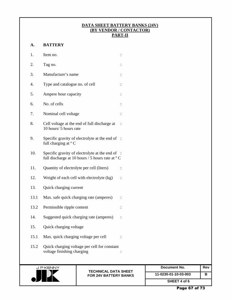
Document No. Rev
11-0230-01-10-03-003 B
TECHNICAL DATA SHEET
FOR 24V BATTERY BANKS SHEET 4 of 6
DATA SHEET BATTERY BANKS (24V)
(BY VENDOR / CONTACTOR) PART-II
A. BATTERY 1. Item no. : 2. Tag no. : 3. Manufacture’s name : 4. Type and catalogue no. of cell : 5. Ampere hour capacity : 6. No. of cells : 7. Nominal cell voltage : 8. Cell voltage at the end of full discharge at : 10 hours/ 5 hours rate 9. Specific gravity of electrolyte at the end of : full charging at º C 10. Specific gravity of electrolyte at the end of : full discharge at 10 hours / 5 hours rate at º C 11. Quantity of electrolyte per cell (liters) : 12. Weight of each cell with electrolyte (kg) : 13. Quick charging current 13.1 Max. safe quick charging rate (amperes) : 13.2 Permissible ripple content : 14. Suggested quick charging rate (amperes) : 15. Quick charging voltage 15.1 Max. quick charging voltage per cell : 15.2 Quick charging voltage per cell for constant voltage finishing charging :
Page 67 of 73
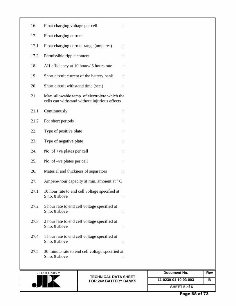
Document No. Rev
11-0230-01-10-03-003 B
TECHNICAL DATA SHEET
FOR 24V BATTERY BANKS SHEET 5 of 6
16. Float charging voltage per cell : 17. Float charging current 17.1 Float charging current range (amperes) : 17.2 Permissible ripple content : 18. AH efficiency at 10 hours/ 5 hours rate : 19. Short circuit current of the battery bank : 20. Short circuit withstand time (sec.) : 21. Max. allowable temp. of electrolyte which the cells can withstand without injurious effects 21.1 Continuously : 21.2 For short periods : 22. Type of positive plate : 23. Type of negative plate : 24. No. of +ve plates per cell : 25. No. of –ve plates per cell : 26. Material and thickness of separators : 27. Ampere-hour capacity at min. ambient at º C 27.1 10 hour rate to end cell voltage specified at
S.no. 8 above : 27.2 5 hour rate to end cell voltage specified at S.no. 8 above : 27.3 2 hour rate to end cell voltage specified at S.no. 8 above : 27.4 1 hour rate to end cell voltage specified at S.no. 8 above : 27.5 30 minute rate to end cell voltage specified at S.no. 8 above :
Page 68 of 73

Document No. Rev
11-0230-01-10-03-003 B
TECHNICAL DATA SHEET
FOR 24V BATTERY BANKS SHEET 6 of 6
28. Dimensions of each battery rack : 28.1 Width (mm) : 28.2 Depth (mm) : 28.3 Height (mm) : 29. Number of battery racks :
Page 69 of 73

GAIL (India) Limited CHAINSA - JHAJJAR PIPELINE PROJECT
CLIENT JOB NO. 110230TECHNICAL DATA SHEET FOR
LT POWER & CONTROL CABLES TOTAL SHEETS 03
DOCUMENT NO 11 0230 01 10 03 004
B 26/08/08 ISSUED FOR TENDER SB SP PKS A 15/07/08 ISSUED FOR REVIEW SB SP PKS
REV DATE DESCRIPTION PREP CHK APPR
Page 70 of 73

Document No. Rev
11-0230-01-10-03-004 B
TECHNICAL DATA SHEET
FOR LT POWER & CONTROL CABLES SHEET 2 of 3
LT POWER CABLE DATA SHEET Part-1
(Data by Purchaser) 1. SITE CONDITIONS a) Ambient temperature : Max. : 50ºC Min. : 10ºC 2. SYSTEM PARAMETERS a) Voltage : Nominal System Voltage Highest System Voltage Voltage grade
415 V 500 V 1100 V b) Frequency : 50 Hz ± 3 % 3. CONDUCTOR MATERIAL
i) LT Power Cables : Aluminum (25 mm² & above) and Copper (up to 16 mm²)
ii) Control Cables : Copper 4. SPECIFIC REQUIREMENTS a) Cable to be Flame Retardant Low Smoke : Yes b) Type of sheath and armour bonding system
adopted for single core cables : N.A. c) Whether installation falls under the
jurisdiction of Directorate General of Mines Safety : No
d) Make of accessories (if applicable) : N.A. e) Type of cable accessories (if applicable) : N.A. f) Drum length required : By Contractor (Indicate whether standard drum lengths as per specification or specific durm lengths are required) Note : N.A. = Not Applicable
Page 71 of 73

Document No. Rev
11-0230-01-10-03-004 B
TECHNICAL DATA SHEET
FOR LT POWER & CONTROL CABLES SHEET 3 of 3
LT POWER CABLE DATA SHEET
Part 2 (Data by Vendor/ Contractor)
1 GENERAL a) Name of manufacturer : b) Cable type / code : c) Year of manufacturing : 2 TECHNICAL PARTICULARS (TO BE FURNISHED SEPARATELY FOR EACH SIZE) a) Size of cable : b) No. of strand : c) Conductor material : d) Thickness of insulation : e) Thickness of inner sheath : f) Calculated diameter of cable : Under armour (as per IS:10462) g) Material/ Type and size of armour : h) Nominal diameter of cable under : outer sheath i) Calculated diameter of cable under outer sheath : j) Thickness of outer sheath : k) Nominal outer diameter of cable : l) Tolerance on outer diameter : m) Type of compound for conductor : insulation, inner sheath and
outer sheath n) Max. Drum length of cable :
Page 72 of 73

Page 73 of 73