Embed Size (px)
Citation preview

Agilent Ion Pumps2-3 Ion Pumps Features and Benefits4-5 Controllers Features and Benefits6-7 SEM Pump Controller Features and Benefits8-11 Typical Applications12-38 Pump Models and Controllers39-49 Technical Notes50-51 Service and Support Plan
��������� ������� ����������� ��� ��������������

2
Agilent Ion Pumps Features and Benefits
Ion Pump Evolution• Since the late 1950’s, when the ion pump was invented at Varian, now Agilent
Technologies, many changes and technical improvements have taken place.Virtually all of the major innovationshave come from us, from the first Diode VacIon pump to the Triode, thento the StarCell series pumps, and theVacIon Plus.
VacIon Plus• VacIon Plus is a complete family of ion
pumps, controllers, options, andaccessories, designed to provide solutions to every application. Parameterssuch as operating pressure, the gas mixture to be pumped, the startingpressure, etc. can vary so dramatically that Varian, today Agilent, decided todevelop dedicated ion pump solutions (including controllers and all otheraccessories) for different applications.
• The VacIon Plus family includes Diode, Noble Diode, and StarCell pumpversions that allow Agilent to provide the best technology for each field ofapplication. The family is complemented by the new 4UHV Ion Pumpcontrollers, that provide different power levels and interface capabilities.
Titanium Sublimation Combination Pumps (TSP)• The titanium sublimation creates extra high getterable gas pumping speed
while the ion pumping mechanisms handle the non-getterable gases such asargon and methane.The combination pump includes the cylindrical cryopanel and TSP sourcemounted to the extra port. Customized pump configurations are also available.
ApplicationSpecificSolutions for SEM:
a complete line ofion getter pumps
dedicated to Electron Microscopy.
Element Cells and Insulators
• Cells’ sizes and geometries areoptimized in order to:- maximize the discharge intensity- maximize the pumping speed.
• The special design of the ceramicinsulators allows:- no buildup of sputtered conductive coating- longer pump life.
Pumping Elements
Three different types of pumpingelements are available to cover allpossible gas mixtures and optimize theapplication specific performances:• Diode.• Noble Diode.• The unique StarCell.
��������� ������� ����������� ��� ��������������

3
Ion
Pum
ps
Ion Pumps
Wide Pumping Speed Range
• Miniature/Appendage pumps from0.2 to 10 l/s.
• Small/Medium pumps from 20 to 75 l/s.• Large size pumps from 150 to 500 l/s.• TSP/Combi pumps.• Custom solutions / larger sizes
available.
Feedthroughs
• Eliminate corrosion.• Implement the “High Voltage Cable
Interlock”.• Provide an easy connection.• Prevent unintentional extraction.• Minimize overall dimensions.
Cables
• Agilent cables have an “HV SafetyInterlock” that prevents any chance ofelectrical shock.
• If the cable is disconnected from the pump, the voltage is automatically cut off.
• Available in different lengths.• Robust, flexible metal-sheathed cable.• 107 Gy radiation tolerance.
Heaters
• The pump can be supplied withheaters designed to perform the pump baking.
• Minimize operational costs.
Vacuum Processing
In order to ensure cleanliness, allpumps are:• Factory processed at high temperature
(450°) in ultra-high vacuum for athorough outgassing of the body andall internal components.
• Shipped under vacuum, and an RGAspectrum can be provided with eachpump.
Custom Design
The pump body can be configured tomeet optional requirements including:• Cryopanel and TSP side or bottom
mounted.• NEG modules.• Integral heaters.• Additional roughing ports.
��������� ������� ����������� ��� ��������������
More Choice and Flexibility• The VacIon Plus pump family is complemented by the new 4UHV Ion Pump
controller, that provides different power levels and interface capabilities.• The compact MiniVac controller, and a dedicated TSP controller
is also available.• The new series of IPCU controller units completes Agilent's offer
(see next pages).• The existing range of ion pump controllers offers more choice and flexibility
than ever before. With the latest in design features, they are simple and easyto operate; just select the right controller to fit your specific application.
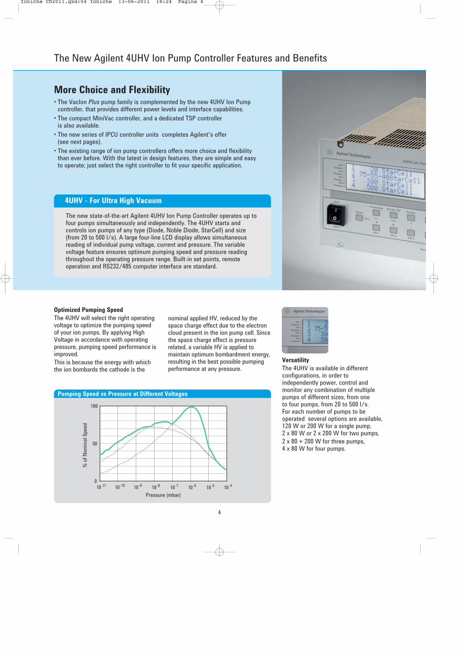
The new state-of-the-art Agilent 4UHV Ion Pump Controller operates up tofour pumps simultaneously and independently. The 4UHV starts andcontrols ion pumps of any type (Diode, Noble Diode, StarCell) and size(from 20 to 500 l/s). A large four-line LCD display allows simultaneousreading of individual pump voltage, current and pressure. The variablevoltage feature ensures optimum pumping speed and pressure readingthroughout the operating pressure range. Built-in set points, remoteoperation and RS232/485 computer interface are standard.
4UHV - For Ultra High Vacuum
Optimized Pumping Speed
The 4UHV will select the right operatingvoltage to optimize the pumping speedof your ion pumps. By applying HighVoltage in accordance with operatingpressure, pumping speed performance isimproved. This is because the energy with whichthe ion bombards the cathode is the
Versatility
The 4UHV is available in differentconfigurations, in order toindependently power, control andmonitor any combination of multiplepumps of different sizes, from one to four pumps, from 20 to 500 l/s. For each number of pumps to beoperated several options are available,120 W or 200 W for a single pump, 2 x 80 W or 2 x 200 W for two pumps,2 x 80 + 200 W for three pumps,4 x 80 W for four pumps.
nominal applied HV, reduced by thespace charge effect due to the electroncloud present in the ion pump cell. Sincethe space charge effect is pressurerelated, a variable HV is applied tomaintain optimum bombardment energy,resulting in the best possible pumpingperformance at any pressure.
0
100
Pressure (mbar)
% o
f Nom
inal
Spee
d
50
10-11 10-10 10-9 10-8 10 -7 10-6 10-5 10 -4
Pumping Speed vs Pressure at Different Voltages
4
The New Agilent 4UHV Ion Pump Controller Features and Benefits
��������� ������� ����������� ��� ��������������

Pressure Reading
The 4UHV is preprogrammed toautomatically convert current reading of any Vaclon Plus pump into pressure.Thanks to its ability to detect ion currentas low as 10 nA, it allows pressuremeasurement in the 10-10 mbar range.To ensure reliable pressure readingdown to the UHV region, the 4UHVoptimizes the applied high voltage as a function of pressure. As a result, theleakage current of the ion pump iseliminated, thereby providing moreaccurate pressure readings.
Intelligence
To access the unit you can use analogor RS232/485 ports. The controller uses the same protocol as our otherintelligent vacuum devices (Navigatorturbo pump Controller and Inverterscroll & rotary vane pumps), giving youfast, convenient access to all elementsof the vacuum system.Profibus and Ethernet communicationsavailable on request, please call Agilentfor details.
Low Noise
For SEM applications especially, theremaining AC component of the HVoutput was reduced to a minimum. It ismuch lower than in any other existingunit, eliminating the need for additionalfilters completely in many cases.
0,1 μ
Pressure (mbar)
Curre
nt (A
)
1 μ
10-10 10-9 10-8 10-7 10-6 10-5
10 μ
100 μ
1000 μ Typical Leakage Current Areawith Conventional Controller
4UHV Reading
Typical Current vs Pressure Curve
5
Ion
Pum
ps
Safety
To protect you against high voltage thecable is equipped with an interlocksystem which immediately shuts downthe high voltage when the plug isremoved from the pump. The protectmode limits the current to protect thepump and the controller.
Ion Pumps
��������� ������� ����������� ��� ��������������

The Agilent Advantage:
Dedicated Solutions for SEM Applications• Agilent is the only manufacturer to offer specially designed SEM ion pumps.
These pumps are ideal for the high vacuum guns where stable vacuum and low leakage current is required to control and preserve the chargedparticle filament.
• The key to this superior performance is Agilent’s patented anode designwhich uses contoured cells and simplified electrical elements. This insuresstable current readings and lower particle generation.
• When combining the SEM ion pump on the gun with a StarCell ion pump onthe lower column, Agilent ion pumps can offer a powerful combinationoptimised for modern E-beam columns.
SEM Ion Pumps are available on request; please ask Agilent for technical details.
Carl Zeiss SMT, global leader in light, electron and ion-optical technologies forindustry and R&D, has designated Agilent Technologies Vacuum ProductsDivision as a Carl Zeiss SMT Supply Chain Partner.
Supply Chain PartnerCarl Zeiss SMT AG
Innovative SEM Anode Geometry
• Better current stability.• Lowest leakage current in the industry
(< 10 nA).• Double Shielded Ceramics.• Longer pump life.• Longer pressure stability.• Maximum uptime.
Wide, Dedicated Range
• A complete range of SEM ion pumpsfrom 10 to 75 l/s, tailored to yourspecific vacuum needs.
• Small footprint for easier systemintegration.
Very Compact Design
Improved design for:• Lighter pump weight.• Fast magnets replacement.• Easy maintenance.
IPCU3 / IPCU 2 Power Supplies
Two versions: 3 or 2 supply channels.• Special low noise electronics for
better SEM imaging.• Battery backup (optional): up to 30
days 24/7 of battery life.• Pressure reading down to –10 range.• Optional display and front panel.New 4UHV Controller
• Special low noise electronics forbetter SEM imaging.
6
Agilent SEM Ion Pumps Features and Benefits
��������� ������� ����������� ��� ��������������

Agilent Feedthrough and Cables
• The HV Safety Interlock prevents anychance of electrical shock.
• The voltage is automatically cut off assoon as the cable is disconnectedfrom the pump.
• Safer pump operation.
Higher Pumping Speed
• Optimized magnetic circuit for max.performance in a very compactpackage.
• Faster pump down.
Dedicated Heaters
• Dedicated Heater for every pump size.• The new heaters are designed to
perform a more effective pump baking.• Lower power and operational costs.
Battery Power Supply
• Enables service without breakingvacuum.
• Allows for column shipping undervacuum.
Dedicated Magnetic Stray Shields
• External magnetic shields for straymagnetic field reduction available.
RGA Guaranteed Ultimate Vacuum
• The pump is vacuum processed at 450 °C to outgas most of gases outof the pump body.
• The pump is shipped under vacuum.• An RGA spectrum is available for each
pump, to guarantee its performanceand the cleanliness of themanufacturing process.
Optical Baffle
Buit-in Optical Baffle (optional) for:• Minimized particle emission.• Minimum conductance reduction.• Total column protection.• Maximum e-gun life.
Available in Round Shape
Integrated ion pump/column allows:• Optimum mass balancing.• Improved pumping conductance.• Compact and modular design.• Simmetric weight distribution for
rugged column integration.
7
Ion
Pum
ps
Ion Pumps
��������� ������� ����������� ��� ��������������

Typical Applications for Agilent VacIon Plus Pumps
8
Research and DevelopmentParticle Accelerators & Synchrotron Light SourcesIn these machines, electrically charged particles (electrons for the production of synchrotron light or ions forparticle accelerators) are forced to follow a curved trajectoryin a ring called a storage ring. Charged particles circulate forhours in the storage ring, at constant energy, in an ultra-highvacuum environment.Before their injection into the storage ring, the particles firsthave to be accelerated inside an injection system composedof one or two accelerators (the Linac and the Booster).All along their path within the machine, the particles(electrons or ions) have to circulate inside a vacuumchamber. Otherwise, they would collide with the airmolecules and would be absorbed very rapidly.• Linac
The linac is a linear accelerator. The charged particles enterinto a first RF cavity which accelerates them and at thesame time groups them into bunches. They are thenaccelerated by a succession of RF cavities throughout thelength of the linac. Vacuum within the linac can be createdby Agilent VacIon Plus pumps from 20 l/s to 70 l/s.
• BoosterCharged particles, which have already been accelerated inthe linac, are accelerated even more strongly by thebooster. The acceleration is produced by RF cavitiesthrough which the charged particles pass many times,gaining in energy at each pass. Once the level of maximumenergy has been reached, the beam of particles istransferred from the booster to the storage ring.
Courtesy CERN. Courtesy Pacific Northwest National Laboratory.
Courtesy: LBNL Advanced Light Source.
Vacuum in the booster is generally produced by small pumps. Small Agilent VacIon Plus pumps fit this application perfectly.
��������� ������� ����������� ��� ��������������

9
Ion
Pum
ps
• Storage RingCharged particles circulate inside the storage ring atconstant energy. All along the ring there are curvedsections as well as straight sections. The storage ring isplaced inside a tunnel with very thick concrete walls inorder to contain emitted radiation in case of beam loss.Ultra high vacuum is an absolute necessity in this part ofthe machine since the particles travel through the storagering for hours. The less residual gas there is, the morefocused the beam remains. Large Agilent VacIon Pluspumps, in the 300 - 500 l/s range are used for thisdemanding application.
• Front EndsThe front end is the pipe work which transports theparticles under a vacuum from the extraction zone up to thebeamline outside of the tunnel of the ring. There you canfind a beam shutter as well as devices allowing theisolation of the vacuum of the ring from that of thebeamline, which is often of lower pressure. Agilent largepumps, as in for the storage ring, can be used in this part ofthe machine.
• Beam LinesThe experimental hall, around the storage ring, houses thebeamlines built tangentially to the ring. The beamlines areusually specialized in a field of research (such as biology,polymers, and magnetism) or an experimental method(such as diffraction, EXAFS, and imaging). Some of thelongest beamlines are built outside the experimental hall.Generally, large pumps are used in this part, from 300 l/s to500 l/s. They can be combined with TSP and cryopanel inorder to pump even the lightest molecules.
• Miscellaneous ProjectsSome fundamental research projects that use very sensitiveequipment (necessitating ultra-high vacuum with nomechanical vibration) will find the solution in AgilentVacIon Plus pumps. The new gravitational waves detectors(GWD) such as VIRGO in Italy and LIGO in the USA useAgilent pumps to produce and maintain the requiredvacuum.
Courtesy PSI SLS.
Courtesy P. Ginter - ESRF Grenoble.
Courtesy P. Ginter - ESRF Grenoble.
Ion Pumps
��������� ������� ����������� ��� ��������������

Agilent Turbo-V Pumps Typical Applications
10
Mass Spectrometry
• Analytical systems that use focused charged particlebeams (CPB) and certain types of mass spectrometers suchas magnetic sector or Fournier Transfer often require ultra-high vacuum.
• These applications have very stringent performancerequirements for sensitivity, resolution, sample throughputand measurement repeatability. These requirements aredriven by the need to analyze ever-smaller samples,especially in semiconductor, manufacturing, and other high-tech applications.
• In general these applications require very clean vacuumpumping, and only VacIon pumps can certify the requiredlevel of cleanliness because Agilent is the only ion pumpmanufacturer that bakes each pump in a vacuum furnace,and supply each pump with an RGA scan.
• Agilent offers a full range of pumps, from 0.2 l/s up to 500 l/s, as well as combination and custom pumps soanalytical system designers can meet all their vacuumrequirements from one supplier.
• Over 50 years of ion pump experience makes Agilentuniquely qualified to supply customized solutions forspecial applications.
Nanotechnologies
• Agilent`s line of high performance VacIon ion pumps arewell suited for the vacuum requirements of TransmissionElectron Microscopes (TEM), Scanning ElectronMicroscopes (SEM), Focused Ion Beam (FIB) and SurfaceAnalysis equipments.
• Agilent is the only manufacturer to offerSEM application-specific ion pumps withunique anode design
Supply Chain PartnerCarl Zeiss SMT AG
• The Diode SEM pump with its extremely low leakagecurrent is ideal for the gun section of the column.
• The StarCell pump elment with its unique design is theideal solution for the high pressure operation of thecolumns. StarCell is also the best pump for noble gases or hydrogen.
• Agilent completes its offering to the microscopemanifacture with a full line of controller/power suppliesincluding the low cost power supplies and the full feature,multiple controllers.
• With the addition of Agilent complete line of oil-free, lowvibration turbo pumps - ideal for sample chamber vacuumrequirements – roughing pumps and vacuum gauges,Agilent can supply all the vacuum components required forelectron microscopes.
• Carl Zeiss SMT, global leader in light, electron and ion-optical technologies for industry and R&D, hasdesignated Agilent Technologies Vacuum Products Divisionas a Carl Zeiss SMT Supply Chain Partner.
Industrial Vacuum Processes
Different applications in industrial sectors such astelecommunication, defense, medical and others make use of
VacIon pumps to process and maintain essentialcomponents under vacuum. Most of the coreequipment in these sectors requires the use ofdifferent electron devices including:• Microwave tubes and devices
• Power grid tubes
• X-ray imaging tubes and devices
• X-ray sources
In the processing cycle of these types of electron devices,small ion pumps from 10 l/s to 50 l/s are being used. Special tube sizes or special applications may require even
Supply Chain PartnerCarl Zeiss SMT AG
��������� ������� ����������� ��� ��������������

11
bigger ion pumps up to 300-500 l/s. VacIon pumps are oftenbeing used in combination with Turbo Molecular Pumps,backing pumps and other components out of the wide rangeof Agilent products. After processing, frequently these electron devices are beingequipped with so-called appendage ion pumps in the range of0.2 l/s to 10 l/s for the purpose of maintaining the electrontube under vacuum for its operational lifetime.The first ion pump was invented by Varian, now Agilent, inthe late 1950’s, for the production of high-quality vacuumtubes used in radar technology. From this point on, VacIonpumps set the pace in the industrial field for a wide range ofapplications using vacuum processed electron devices usedworldwide in:• Space
Electron devices are essential to various space programs,from satellite services and earth observation satellites tospace probes. Microwave tubes and devices are vital tools,which link people and satellites in order to enable globalcommunications. Spaceborne tubes are the powergenerators for the transponders carried on satellites. They retransmit TV or telecommunication signals back tothe ground. The electron tubes used for this application areTravelling Wave Tubes. In these tubes, amplification isproduced under vacuum by the interaction between a beamof electrons and the Radio-Frequency (RF) wave.
• TelecommunicationsMicrowave tubes, devices like Traveling Wave Tubes(TWTs) and Klystrons (powerful radio vacuum tubes) arewidely used in civil and military telecommunicationnetworks and equipment used for: - Satellite and terrestrial communication- High data-rate transmissions for High Speed Internet and
Wireless Cable- Broadband high speed data- Point-to-point and point-to-multipoint microwave links.
• BroadcastRadio and TV broadcasters and transmitter manufacturersuse electron devices in their equipment to enable high powertransmission or digital broadcasting. Power grid tubes ormicrowave tubes are being used in AM radio, FM radio,VHF TV, UHF TV or digital TV transmitters and amplifiers.
• MedicalRadiological equipment manufacturers use electron devicesfor critical components in the radiological chain, such as X-ray image intensifiers and radiological imaging units fordiagnostics, as well as medical linear accelerators forradiation therapy. Typical fields of application include:- Medical Imaging (X-ray image tubes and devices) - Radiation Therapy (high power Klystrons, LINAC)- Magnetic Resonance Imaging.
• DefenseMicrowave tubes and devices are key components inequipment and systems used for different defense applications:- Radar (ground based or airborne)- Electronic Countermeasures (ECM)- Smart Weapons & Electronic Warfare- Missile guidance & Missile seekers
• Industrial and OthersSeveral industrial processes make use of RF & Microwavetubes. Some examples are heat treating, Plastic welding,Food processing, Textile manufacturing, Film curing & drying. Other applications make use of X-ray tubes fornon-destructive testing methods.
Courtesy CPI.
Courtesy University of Modena.
Ion
Pum
ps
Ion Pumps
��������� ������� ����������� ��� ���������������

12
Agilent Ion Pump Models
Miniature Pump 2 l/s Pump 10 l/s Pump Vaclon Plus 20 Vaclon Plus 40
Inlet Flange 2 ¾” OD CFF (NW 35) 2 ¾” OD CFF (NW 35)
Element Type Diode Diode Diode StarCell Noble Diode Diode StarCell Noble Diode Diode
Pumping Speed (l/s)(Saturated Pump at 1-6 mbar)Nitrogen 0.2 2 10 20 22 27 34 36 40
Operating Life (Hours) (at 1-6 mbar) N/A 8 40 80 50 50 80 50 50
Maximum Starting Pressure (mbar) 1 x 10⁻⁴ 1 x 10⁻⁴ ≤ 1 x 10⁻⁴ <10-2 <10-3 <10-3 <10-2 <10-3 <10-3
400 (without magnet) 400 (without magnet)Maximum Baking Temperature (°C) 150 (with magnet) 150 (with magnet) 350 350 350 350 350 350 350
Net 0.3 (0.66) Net 0.3 (0.66) Without magnet Net 7 (15) Net 17 (37)Weight kg (Ibs) Shipping 0.6 (1.33) Shipping 0.6 (1.33) 4 (9) Shipping 11 (24) Shipping 21 (46)
SEM Version Available on Request - - + + +
��������� ������� ����������� ��� ���������������

13
Ion
Pum
ps
Vaclon Plus 55 Vaclon Plus 75 Vaclon Plus 150 Vaclon Plus 300 Vaclon Plus 500
4 ½” OD CFF (NW 63) 6" OD CFF (NW 100) 6" OD CFF (NW 100) 8" OD CFF (NW 150) 8" OD CFF (NW 150)
StarCell Noble Diode Diode StarCell Noble Diode Diode StarCell Noble Diode Diode StarCell Noble Diode Diode StarCell Noble Diode Diode
50 53 55 65 68 75 125 135 150 240 260 300 410 440 500
80 50 50 80 50 50 80 50 50 80 50 50 80 50 50
<10-2 <10-3 <10-3 <10-2 <10-3 <10-3 <10-2 <10-3 <10-3 <10-2 <10-3 <10-3 <10-2 <10-3 <10-3
350 350 350 350 350 350 350 350 350 350 350 350 350 350 350
Net 18 (39) Net 19 (42) Net 43 (94) Net 69 (149) Net 120 (264)Shipping 22 (48) Shipping 23 (51) Shipping 53 (110) Shipping 84 (185) Shipping 135 (297)
+ + - - -
Ion Pumps
��������� ������� ����������� ��� ���������������

Agilent Ion Pump Models
Agilent VacIon Plus 20
23/4" CFF (NW35)
224 (8.80) REF
152
(6.0
0) R
EF
133 (5.20) REF24 (0.90) REF
121 (4.80) REF
Technical Specifications
StarCell Noble Diode Diode
Nominal pumping speed for Nitrogen (*) (l/s) 20 22 27Operating life at 1x10⁻⁶ mbar (hours) 80,000 50,000 50,000Maximum starting pressure (mbar) ≤ 5x10⁻² ≤ 1x10⁻³ ≤ 1x10⁻³
Ultimate pressure Below 10-11
Inlet flange 2 ¾” CFF (NW 35) AISI 304 ESR SSTMaximum baking temperature (°C) 350Weight, kg (Ibs) (with ferrite magnet) Net 7 (15), Shipping 11 (24)(*) Tested according to ISO/DIS 3556-1-1992
Dimensions: millimeters (inches)
SEM version available on request
14
��������� ������� ����������� ��� ���������������
Ion
Pum
ps
Pressure (mbar)
Pum
ping
Spee
d (l/
s)
20
010-11 10-10 10-9 10-8
30
10
40
10-7 10-6 10-5 10-4 Nitrogen unsaturated DiodeNitrogen saturated DiodeArgon saturated StarCell
15
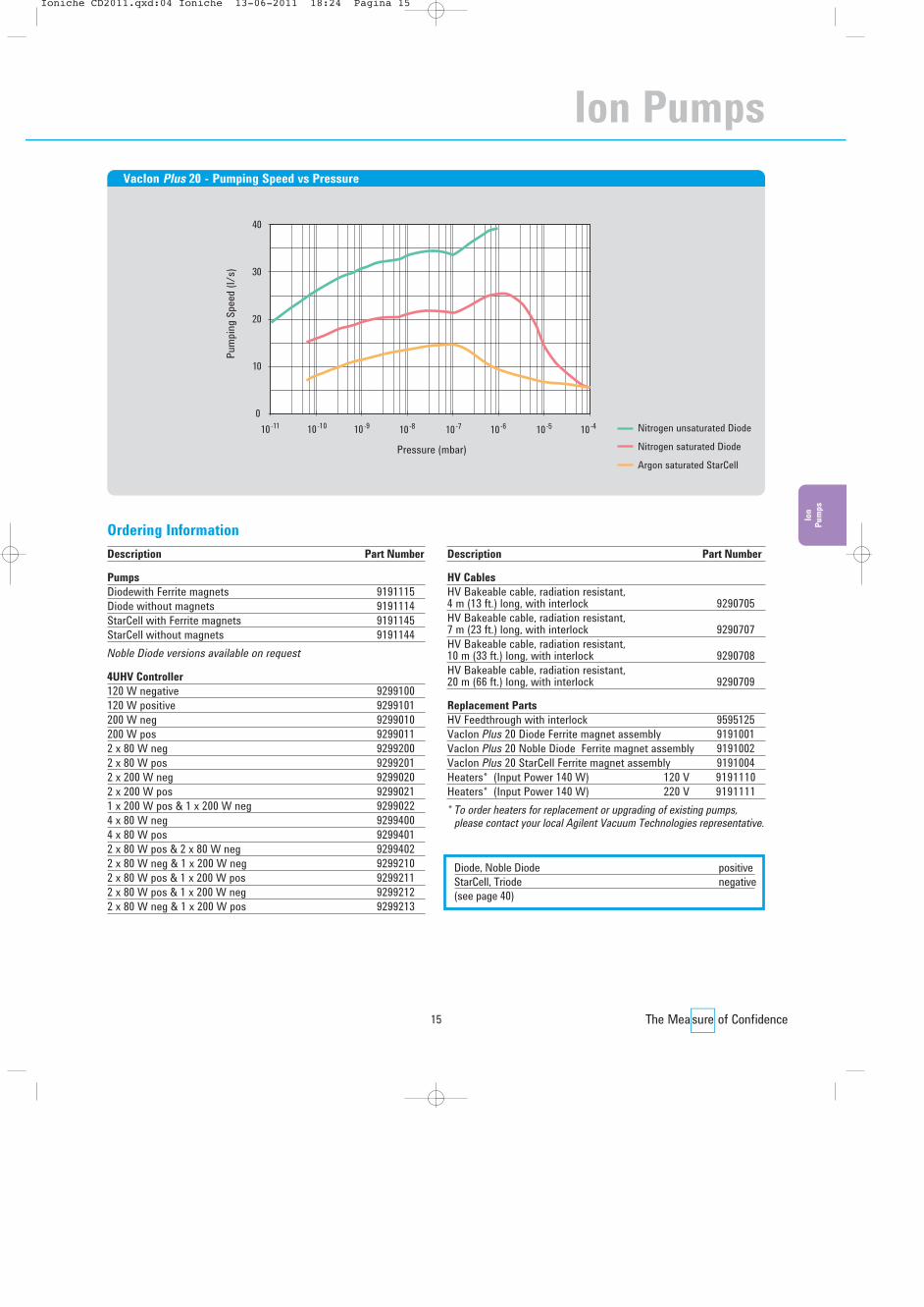
VacIon Plus 20 - Pumping Speed vs Pressure
Description Part Number
Pumps
Diodewith Ferrite magnets 9191115Diode without magnets 9191114StarCell with Ferrite magnets 9191145StarCell without magnets 9191144Noble Diode versions available on request
4UHV Controller
120 W negative 9299100 120 W positive 9299101 200 W neg 9299010 200 W pos 9299011 2 x 80 W neg 9299200 2 x 80 W pos 9299201 2 x 200 W neg 9299020 2 x 200 W pos 92990211 x 200 W pos & 1 x 200 W neg 9299022 4 x 80 W neg 9299400 4 x 80 W pos 92994012 x 80 W pos & 2 x 80 W neg 9299402 2 x 80 W neg & 1 x 200 W neg 9299210 2 x 80 W pos & 1 x 200 W pos 92992112 x 80 W pos & 1 x 200 W neg 92992122 x 80 W neg & 1 x 200 W pos 9299213
Description Part Number
HV Cables
HV Bakeable cable, radiation resistant, 4 m (13 ft.) long, with interlock 9290705HV Bakeable cable, radiation resistant, 7 m (23 ft.) long, with interlock 9290707HV Bakeable cable, radiation resistant, 10 m (33 ft.) long, with interlock 9290708HV Bakeable cable, radiation resistant, 20 m (66 ft.) long, with interlock 9290709
Replacement Parts
HV Feedthrough with interlock 9595125VacIon Plus 20 Diode Ferrite magnet assembly 9191001VacIon Plus 20 Noble Diode Ferrite magnet assembly 9191002VacIon Plus 20 StarCell Ferrite magnet assembly 9191004Heaters* (Input Power 140 W) 120 V 9191110Heaters* (Input Power 140 W) 220 V 9191111* To order heaters for replacement or upgrading of existing pumps,
please contact your local Agilent Vacuum Technologies representative.
Ordering Information
Diode, Noble Diode positiveStarCell, Triode negative(see page 40)
Ion Pumps
��������� ������� ����������� ��� ���������������

16
Agilent Ion Pump Models
Agilent VacIon Plus 40
57 (2
.24)
RE
F
2 3/4" CFF (NW35)
310 (12.20) REF
217.
50 (8
.56)
RE
F
160.50 (6.32) REF
4 HOLES M6
60 (2.36) REF = =160 (6.30) REF
136.
50 (5
.37)
RE
F
==
==
Technical Specifications
StarCell Noble Diode Diode
Nominal pumping speed for Nitrogen (*) (l/s) 34 36 40Operating life at 1x10⁻⁶ mbar (hours) 80,000 50,000 50,000Maximum starting pressure (mbar) ≤ 5x10⁻² ≤ 1x10⁻³ ≤ 1x10⁻³
Ultimate pressure Below 10-11
Inlet flange 2 ¾” CFF (NW 35) AISI 304 ESR SSTMaximum baking temperature (°C) 350Weight, kg (Ibs) 17 (37)(*) Tested according to ISO/DIS 3556-1-1992
Dimensions: millimeters (inches)
SEM version available on request
��������� ������� ����������� ��� ���������������

17
Ion
Pum
ps
Pressure (mbar)
Pum
ping
Spee
d (l/
s)
30
010-11 10-10 10-9 10-8
45
15
60
10-7 10-6 10-5 10-4 Nitrogen unsaturated DiodeNitrogen saturated DiodeArgon saturated StarCell
VacIon Plus 40 - Pumping Speed vs Pressure
Description Part Number
Pumps
Diode 9191210Diode with additional 2 ¾” CFF port 9191213Diode without magnets 9191214StarCell 9191240StarCell with additional 2 ¾” CFF port 9191243StarCell without magnets 9191244Noble Diode versions available on request
4UHV Controller
120 W negative 9299100 120 W positive 9299101 200 W neg 9299010 200 W pos 9299011 2 x 80 W neg 9299200 2 x 80 W pos 9299201 2 x 200 W neg 9299020 2 x 200 W pos 92990211 x 200 W pos & 1 x 200 W neg 9299022 4 x 80 W neg 9299400 4 x 80 W pos 92994012 x 80 W pos & 2 x 80 W neg 9299402 2 x 80 W neg & 1 x 200 W neg 9299210 2 x 80 W pos & 1 x 200 W pos 92992112 x 80 W pos & 1 x 200 W neg 92992122 x 80 W neg & 1 x 200 W pos 9299213
Description Part Number
HV Cables
HV Bakeable cable, radiation resistant, 4 m (13 ft.) long, with interlock 9290705HV Bakeable cable, radiation resistant, 7 m (23 ft.) long, with interlock 9290707HV Bakeable cable, radiation resistant, 10 m (33 ft.) long, with interlock 9290708HV Bakeable cable, radiation resistant, 20 m (66 ft.) long, with interlock 9290709
Replacement Parts
HV Feedthrough with interlock 9595125Heaters*/** (Input Power 250 W) 120 V 9190071Heaters*/** (Input Power 250 W) 220 V 9190070* To order heaters for replacement or upgrading of existing pumps,
please contact your local Agilent Vacuum Technologies representative.** cCSAus marked version available on request.
Ordering Information
Diode, Noble Diode positiveStarCell, Triode negative(see page 40)
Ion Pumps
��������� ������� ����������� ��� ���������������

18
Agilent Ion Pump Models
Agilent VacIon Plus 55
71.1
6 (2
.80)
RE
F
41/2" CFF (NW63)
60 (2.36) REF160 (6.30) REF
136.
50 (5
.37)
RE
F
310 (12.20) REF
231.
66 (9
.12)
RE
F
160.50 (6.32) REF
4 HOLES M6 ==
Technical Specifications
StarCell Noble Diode Diode
Nominal pumping speed for Nitrogen (*) (l/s) 50 53 55Operating life at 1x10⁻⁶ mbar (hours) 80,000 50,000 50,000Maximum starting pressure (mbar) ≤ 5x10⁻² ≤ 1x10⁻³ ≤ 1x10⁻³
Ultimate pressure Below 10-11
Inlet flange 4 ½” CFF (NW 63) AISI 304 ESR SSTMaximum baking temperature (°C) 350Weight, kg (Ibs) 18 (39)(*) Tested according to ISO/DIS 3556-1-1992
Dimensions: millimeters (inches)
SEM version available on request
��������� ������� ����������� ��� ���������������

19
Ion
Pum
ps
Pressure (mbar)
Pum
ping
Spee
d (l/
s)
50
010-11 10-10 10-9 10-8
75
25
100
10-7 10-6 10-5 10-4 Nitrogen unsaturated DiodeNitrogen saturated DiodeArgon saturated StarCell
VacIon Plus 55 - Pumping Speed vs Pressure
Description Part Number
Pumps
Diode 9191310Diode with additional 2 ¾” CFF port 9191313Diode without magnets 9191314StarCell 9191340StarCell with additional 2 ¾” CFF port 9191343StarCell without magnets 9191344Noble Diode versions available on request
4UHV Controller
120 W negative 9299100 120 W positive 9299101 200 W neg 9299010 200 W pos 9299011 2 x 80 W neg 9299200 2 x 80 W pos 9299201 2 x 200 W neg 9299020 2 x 200 W pos 92990211 x 200 W pos & 1 x 200 W neg 9299022 4 x 80 W neg 9299400 4 x 80 W pos 92994012 x 80 W pos & 2 x 80 W neg 9299402 2 x 80 W neg & 1 x 200 W neg 9299210 2 x 80 W pos & 1 x 200 W pos 92992112 x 80 W pos & 1 x 200 W neg 92992122 x 80 W neg & 1 x 200 W pos 9299213
Description Part Number
HV Cables
HV Bakeable cable, radiation resistant, 4 m (13 ft.) long, with interlock 9290705HV Bakeable cable, radiation resistant, 7 m (23 ft.) long, with interlock 9290707HV Bakeable cable, radiation resistant, 10 m (33 ft.) long, with interlock 9290708HV Bakeable cable, radiation resistant, 20 m (66 ft.) long, with interlock 9290709
Replacement Parts
HV Feedthrough with interlock 9595125Heaters*/** (Input Power 250 W) 120 V 9190071Heaters*/** (Input Power 250 W) 220 V 9190070* To order heaters for replacement or upgrading of existing pumps,
please contact your local Agilent Vacuum Technologies representative.** cCSAus marked version available on request.
Ordering Information
Diode, Noble Diode positiveStarCell, Triode negative(see page 40)
Ion Pumps
��������� ������� ����������� ��� ���������������

20
Agilent Ion Pump Models
Agilent VacIon Plus 75
81.6
0 (3
.21)
RE
F
6" CFF (NW100)
60 (2.36) REF= =160 (6.30) REF
136.
50 (5
.37)
RE
F
310 (12.20) REF
242.
10 (9
.53)
RE
F
160.50 (6.32) REF
4 HOLES M6==
==
Technical Specifications
StarCell Noble Diode Diode
Nominal pumping speed for Nitrogen (*) (l/s) 65 68 75Operating life at 1x10⁻⁶ mbar (hours) 80,000 50,000 50,000Maximum starting pressure (mbar) ≤ 5x10⁻² ≤ 1x10⁻³ ≤ 1x10⁻³
Ultimate pressure Below 10-11
Inlet flange 6” CFF (NW 100) AISI 304 ESR SSTMaximum baking temperature (°C) 350Weight, kg (Ibs) 19 (42)(*) Tested according to ISO/DIS 3556-1-1992
Dimensions: millimeters (inches)
SEM version available on request
��������� ������� ����������� ��� ��������������

21
Ion
Pum
ps
Pressure (mbar)
Pum
ping
Spee
d (l/
s)160
120
010-11 10-10 10-9 10-8 10-7 10-6 10-5 10-4
80
40
Nitrogen unsaturated DiodeNitrogen saturated DiodeArgon saturated StarCell
VacIon Plus 75 - Pumping Speed vs Pressure
Description Part Number
Pumps
Diode 9191410Diode with additional 2 ¾” CFF port 9191413Diode without magnets 9191414StarCell 9191440StarCell with additional 2 ¾” CFF port 9191443StarCell without magnets 9191444Noble Diode versions available on request
4UHV Controller
120 W negative 9299100 120 W positive 9299101 200 W neg 9299010 200 W pos 9299011 2 x 80 W neg 9299200 2 x 80 W pos 9299201 2 x 200 W neg 9299020 2 x 200 W pos 92990211 x 200 W pos & 1 x 200 W neg 9299022 4 x 80 W neg 9299400 4 x 80 W pos 92994012 x 80 W pos & 2 x 80 W neg 9299402 2 x 80 W neg & 1 x 200 W neg 9299210 2 x 80 W pos & 1 x 200 W pos 92992112 x 80 W pos & 1 x 200 W neg 92992122 x 80 W neg & 1 x 200 W pos 9299213
Description Part Number
HV Cables
HV Bakeable cable, radiation resistant, 4 m (13 ft.) long, with interlock 9290705HV Bakeable cable, radiation resistant, 7 m (23 ft.) long, with interlock 9290707HV Bakeable cable, radiation resistant, 10 m (33 ft.) long, with interlock 9290708HV Bakeable cable, radiation resistant, 20 m (66 ft.) long, with interlock 9290709
Replacement Parts
HV Feedthrough with interlock 9595125Heaters*/** (Input Power 250 W) 120 V 9190071Heaters*/** (Input Power 250 W) 220 V 9190070* To order heaters for replacement or upgrading of existing pumps,
please contact your local Agilent Vacuum Technologies representative.** cCSAus marked version available on request.
Ordering Information
Diode, Noble Diode positiveStarCell, Triode negative(see page 40)
Ion Pumps
��������� ������� ����������� ��� ���������������

22
Agilent Ion Pump Models
Agilent VacIon Plus 150
47.8
0 (1
.88)
RE
F
6" O.D. CFF (NW100)
170 (6.69) REF100 (3.94) REF
244.
50 (9
.62)
RE
F
272.50 (10.73) REF
362.
80 (1
4.28
) RE
F
205 (8.07) REF
THREADING 1/2"-20 2B
Technical Specifications
StarCell Noble Diode Diode
Nominal pumping speed for Nitrogen (*) (l/s) 125 135 150Operating life at 1x10⁻⁶ mbar (hours) 80,000 50,000 50,000Maximum starting pressure (mbar) ≤ 5x10⁻² ≤ 1x10⁻³ ≤ 1x10⁻³
Ultimate pressure Below 10-11
Inlet flange 6” CFF (NW 100) AISI 304 ESRMaximum baking temperature (°C) 350Weight, kg (Ibs) 43 (94)(*) Tested according to ISO/DIS 3556-1-1992
Dimensions: millimeters (inches)
SEM version available on request
��������� ������� ����������� ��� ���������������
23
Ion
Pum
ps
Pressure (mbar)
Pum
ping
Spee
d (l/
s)
200
010-11 10-10 10-9 10-8
50
250
150
100
300
10-7 10-6 10-5 10-4 Nitrogen unsaturated DiodeNitrogen saturated DiodeArgon saturated StarCell
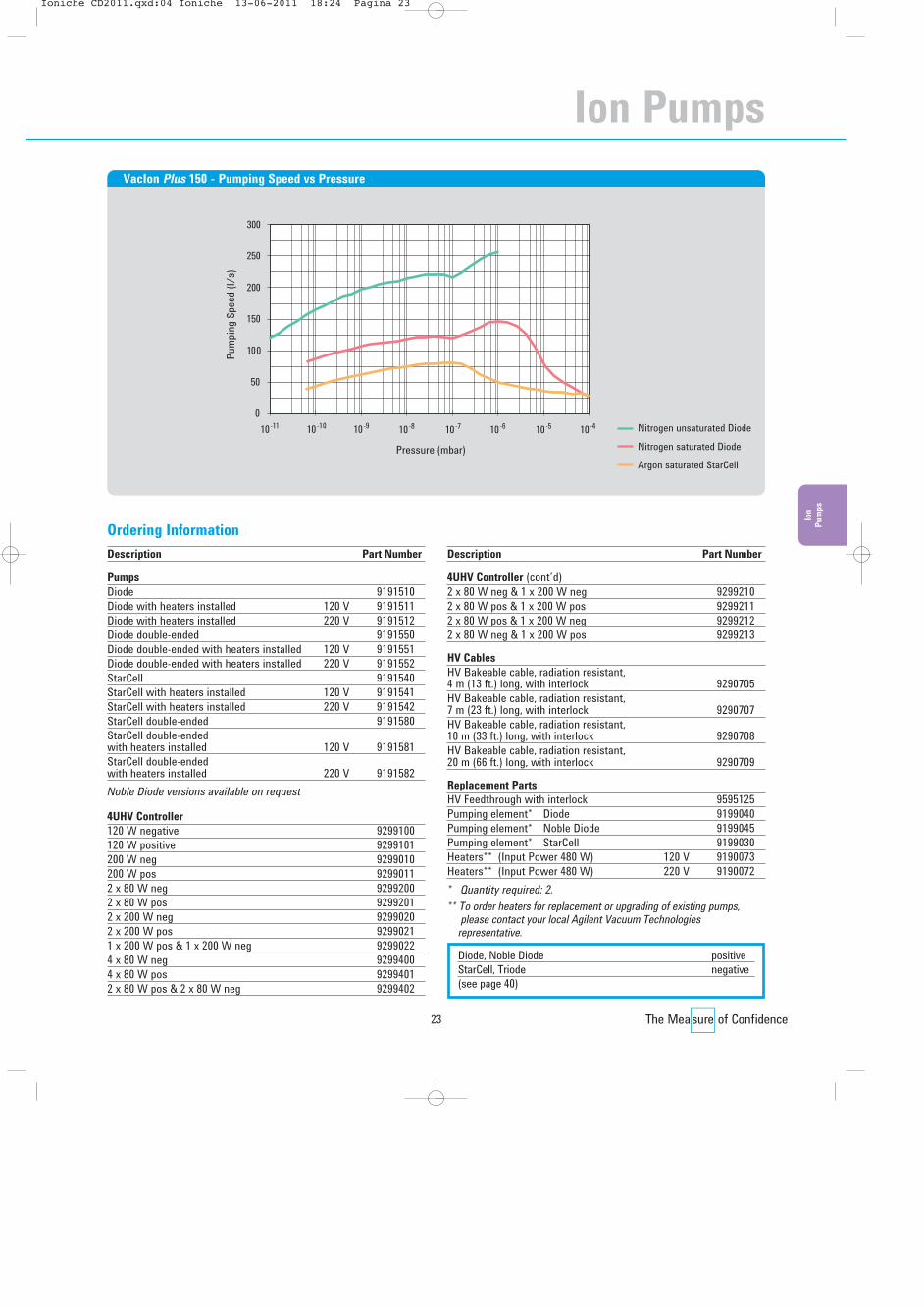
VacIon Plus 150 - Pumping Speed vs Pressure
Description Part Number
Pumps
Diode 9191510Diode with heaters installed 120 V 9191511Diode with heaters installed 220 V 9191512Diode double-ended 9191550Diode double-ended with heaters installed 120 V 9191551Diode double-ended with heaters installed 220 V 9191552StarCell 9191540StarCell with heaters installed 120 V 9191541StarCell with heaters installed 220 V 9191542StarCell double-ended 9191580StarCell double-ended with heaters installed 120 V 9191581StarCell double-ended with heaters installed 220 V 9191582Noble Diode versions available on request
4UHV Controller
120 W negative 9299100 120 W positive 9299101 200 W neg 9299010 200 W pos 9299011 2 x 80 W neg 9299200 2 x 80 W pos 9299201 2 x 200 W neg 9299020 2 x 200 W pos 92990211 x 200 W pos & 1 x 200 W neg 9299022 4 x 80 W neg 9299400 4 x 80 W pos 92994012 x 80 W pos & 2 x 80 W neg 9299402
Description Part Number
4UHV Controller (cont’d)2 x 80 W neg & 1 x 200 W neg 9299210 2 x 80 W pos & 1 x 200 W pos 92992112 x 80 W pos & 1 x 200 W neg 92992122 x 80 W neg & 1 x 200 W pos 9299213
HV Cables
HV Bakeable cable, radiation resistant, 4 m (13 ft.) long, with interlock 9290705HV Bakeable cable, radiation resistant, 7 m (23 ft.) long, with interlock 9290707HV Bakeable cable, radiation resistant, 10 m (33 ft.) long, with interlock 9290708HV Bakeable cable, radiation resistant, 20 m (66 ft.) long, with interlock 9290709
Replacement Parts
HV Feedthrough with interlock 9595125Pumping element* Diode 9199040Pumping element* Noble Diode 9199045Pumping element* StarCell 9199030Heaters** (Input Power 480 W) 120 V 9190073Heaters** (Input Power 480 W) 220 V 9190072* Quantity required: 2.** To order heaters for replacement or upgrading of existing pumps,
please contact your local Agilent Vacuum Technologiesrepresentative.
Ordering Information
Diode, Noble Diode positiveStarCell, Triode negative(see page 40)
Ion Pumps
��������� ������� ����������� ��� ���������������

Agilent Ion Pump Models
Agilent VacIon Plus 300
55.2
0 (2
.17)
RE
F
8" O.D. CFF (NW150)
170 (6.69) REF
THREADING 1/2"-20
130 (5.11) REF
244.
50 (9
.62)
RE
F
450 (17.71) REF
344.
70 (1
3.57
) RE
F
Technical Specifications
StarCell Noble Diode Diode
Nominal pumping speed for Nitrogen (*) (l/s) 240 260 300Operating life at 1x10⁻⁶ mbar (hours) 80,000 50,000 50,000Maximum starting pressure (mbar) ≤ 5x10⁻² ≤ 1x10⁻³ ≤ 1x10⁻³
Ultimate pressure Below 10-11
Inlet flange 8” CFF (NW 150) AISI 304 ESRMaximum baking temperature (°C) 350Weight, kg (Ibs) 69 (149)(*) Tested according to ISO/DIS 3556-1-1992
Dimensions: millimeters (inches)
24
��������� ������� ����������� ��� ���������������

Ion
Pum
ps
Pressure (mbar)
Pum
ping
Spee
d (l/
s)
400
010-11 10-10 10-9 10-8
100
500
300
200
600
10-7 10-6 10-5 10-4 Nitrogen unsaturated DiodeNitrogen saturated DiodeArgon saturated StarCell
VacIon Plus 300 - Pumping Speed vs Pressure
Description Part Number
Pumps
Diode 9191610Diode with heaters installed 120 V 9191611Diode with heaters installed 220 V 9191612Diode double-ended 9191650Diode double-ended with heaters installed 120 V 9191651Diode double-ended with heaters installed 220 V 9191652StarCell 9191640StarCell with heaters installed 120 V 9191641StarCell with heaters installed 220 V 9191642StarCell double-ended 9191680StarCell double-ended with heaters installed 120 V 9191681StarCell double-ended with heaters installed 220 V 9191682Noble Diode versions available on request
4UHV Controller
120 W negative 9299100 120 W positive 9299101 200 W neg 9299010 200 W pos 9299011 2 x 80 W neg 9299200 2 x 80 W pos 9299201 2 x 200 W neg 9299020 2 x 200 W pos 92990211 x 200 W pos & 1 x 200 W neg 9299022 4 x 80 W neg 9299400 4 x 80 W pos 92994012 x 80 W pos & 2 x 80 W neg 9299402
Description Part Number
4UHV Controller (cont’d)2 x 80 W neg & 1 x 200 W neg 9299210 2 x 80 W pos & 1 x 200 W pos 92992112 x 80 W pos & 1 x 200 W neg 92992122 x 80 W neg & 1 x 200 W pos 9299213
HV Cables
HV Bakeable cable, radiation resistant, 4 m (13 ft.) long, with interlock 9290705HV Bakeable cable, radiation resistant, 7 m (23 ft.) long, with interlock 9290707HV Bakeable cable, radiation resistant, 10 m (33 ft.) long, with interlock 9290708HV Bakeable cable, radiation resistant, 20 m (66 ft.) long, with interlock 9290709
Replacement Parts
HV Feedthrough with interlock 9595125Pumping element* Diode 9199040Pumping element* Noble Diode 9199045Pumping element* StarCell 9199030Heaters** (Input Power 580 W) 120 V 9190075Heaters** (Input Power 580 W) 220 V 9190074* Quantity required: 4.** To order heaters for replacement or upgrading of existing pumps,
please contact your local Agilent Vacuum Technologiesrepresentative.
Ordering Information
25
Diode, Noble Diode positiveStarCell, Triode negative(see page 40)
Ion Pumps
��������� ������� ����������� ��� ���������������
Agilent Ion Pump Models
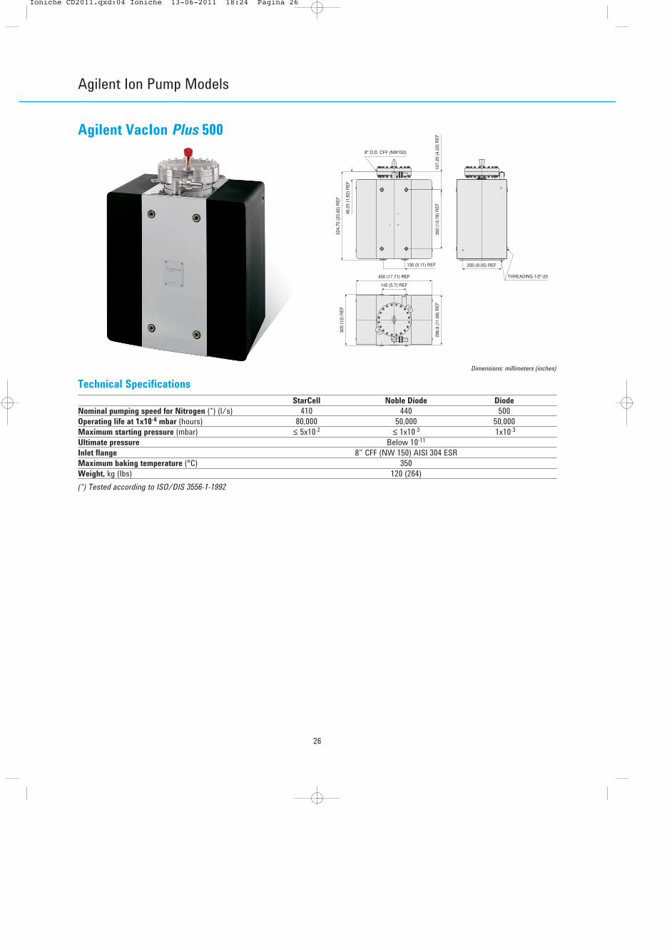
Agilent VacIon Plus 500
107.
25 (4
.22)
RE
F35
0 (1
3.78
) RE
F
46.2
5 (1
.82)
RE
F
8" O.D. CFF (NW150)
230 (9.05) REF
THREADING 1/2"-20
130 (5.11) REF
145 (5.7) REF
296.
8 (1
1.68
) RE
F
305
(12)
RE
F
450 (17.71) REF
524.
70 (2
0.65
) RE
F
Technical Specifications
StarCell Noble Diode Diode
Nominal pumping speed for Nitrogen (*) (l/s) 410 440 500Operating life at 1x10⁻⁶ mbar (hours) 80,000 50,000 50,000Maximum starting pressure (mbar) ≤ 5x10⁻² ≤ 1x10⁻³ 1x10⁻³
Ultimate pressure Below 10-11
Inlet flange 8” CFF (NW 150) AISI 304 ESRMaximum baking temperature (°C) 350Weight, kg (Ibs) 120 (264)(*) Tested according to ISO/DIS 3556-1-1992
Dimensions: millimeters (inches)
26
��������� ������� ����������� ��� ���������������

Ion
Pum
ps
Pressure (mbar)
Pum
ping
Spee
d (l/
s)
400
010-11 10-10 10-9 10-8
100
500
300
200
600
700
800
10-7 10-6 10-5 10-4 Nitrogen unsaturated DiodeNitrogen saturated DiodeArgon saturated StarCell
VacIon Plus 500 - Pumping Speed vs Pressure
Description Part Number
Pumps
Diode 9191710Diode with heaters installed 120 V 9191711Diode with heaters installed 220 V 9191712Diode double-ended 9191750Diode double-ended with heaters installed 120 V 9191751Diode double-ended with heaters installed 220 V 9191752StarCell 9191740StarCell with heaters installed 120 V 9191741StarCell with heaters installed 220 V 9191742StarCell double-ended 9191780StarCell double-ended with heaters installed 120 V 9191781StarCell double-ended with heaters installed 220 V 9191782Noble Diode versions available on request
4UHV Controller
120 W negative 9299100 120 W positive 9299101 200 W neg 9299010 200 W pos 9299011 2 x 80 W neg 9299200 2 x 80 W pos 9299201 2 x 200 W neg 9299020 2 x 200 W pos 92990211 x 200 W pos & 1 x 200 W neg 9299022 4 x 80 W neg 9299400 4 x 80 W pos 92994012 x 80 W pos & 2 x 80 W neg 9299402
Description Part Number
4UHV Controller (cont’d)2 x 80 W neg & 1 x 200 W neg 9299210 2 x 80 W pos & 1 x 200 W pos 92992112 x 80 W pos & 1 x 200 W neg 92992122 x 80 W neg & 1 x 200 W pos 9299213
HV Cables
HV Bakeable cable, radiation resistant, 4 m (13 ft.) long, with interlock 9290705HV Bakeable cable, radiation resistant, 7 m (23 ft.) long, with interlock 9290707HV Bakeable cable, radiation resistant, 10 m (33 ft.) long, with interlock 9290708HV Bakeable cable, radiation resistant, 20 m (66 ft.) long, with interlock 9290709
Replacement Parts
HV Feedthrough with interlock 9595125Pumping element* Diode 9199040Pumping element* Noble Diode 9199045Pumping element* StarCell 9199030Heaters** (Input Power 780 W) 120 V 9190077Heaters** (Input Power 780 W) 220 V 9190076* Quantity required: 8.** To order heaters for replacement or upgrading of existing pumps,
please contact your local Agilent Vacuum Technologiesrepresentative.
Ordering Information
27
Diode, Noble Diode positiveStarCell, Triode negative(see page 40)
Ion Pumps
��������� ������� ����������� ��� ���������������

28
Agilent Ion Pump Models
Agilent VacIon PlusCombination Pumps
Technical Specifications
Nominal net pumping speed at 20°C (l/s) with StarCell elements (water cooled cryopanel)VacIon Plus 150 N2 – 610
H2 – 1,380VacIon Plus 300 N2 – 720
H2 – 1,580VacIon Plus 500 N2 – 880
H2 – 1,930
Titanium Sublimation Combination Pumps
• Ion-Sublimation combination pumps have been a popularchoice for many years for creating ultra high vacuumenvironments. The titanium sublimation creates extra highgetterable gas pumping speed while the ion pumpingmechanisms handle the non-getterable gases such asargon and methane.
• This combination pump is a VacIon Plus 150, 300, or 500with an extra side or bottom-mounted 8” ConFlat port. The combination pump includes the cylindrical cryo paneland TSP source mounted to the extra port. Getterable gasesenter the end of the cylin drical cryo panel and are pumpedby being combined with the freshly-deposited titaniumthere. Liquid nitrogen cooling the cryopanel increases theefficiency of the gettering process and adds greatly to thewater pumping speed.
• The Agilent VacIon Plus series combination pumps allowaddition of a cryopanel from the bottom of the pump orfrom the side. This can be a significant advantage insituations where height restrictions are present.Customized pump configurations are also available.
1/2"-20 2B
123.
50 (
4.86
) R
EF
100.00 (3.94) REF
6" O.D. CFF (NW100)
337.
80 (
13.3
0) R
EF
25.0
0 (.
98)
RE
F
245.50 (9.67) REF
170.00 (6.69) REF
124.35(4.90) REF 200 (7.87) REF 272.50 (10.73) REF
205 (8.07) REF
Vaclon Plus 150 Combination Pump (side-mounted TSP)
449.92 (17.71) REF
124.35(4.90) REF
148.50(5.85) REF
244.45(9.62) REF
170(6.69) REF
8" O.D. CFF (NW150)
348.
65 (
13.7
3) R
EF
123.
50
(4.8
6) R
EF
N4 HOLES Ø1/2"-20 UNC
55.4
5 (2
.18)
RE
F
130 (5.12) REF
Vaclon Plus 300 Combination Pump (side-mounted TSP)52
5 (2
0.67
) R
EF
367.
95 (
14.4
9) R
EF
450 (17.72) REF
8" O.D. CFF (NW150)
297 (11.69) REF142
(5.59) REF
124.35(4.90) REF
Vaclon Plus 500 Combination Pump (side-mounted TSP)
��������� ������� ����������� ��� ���������������
29
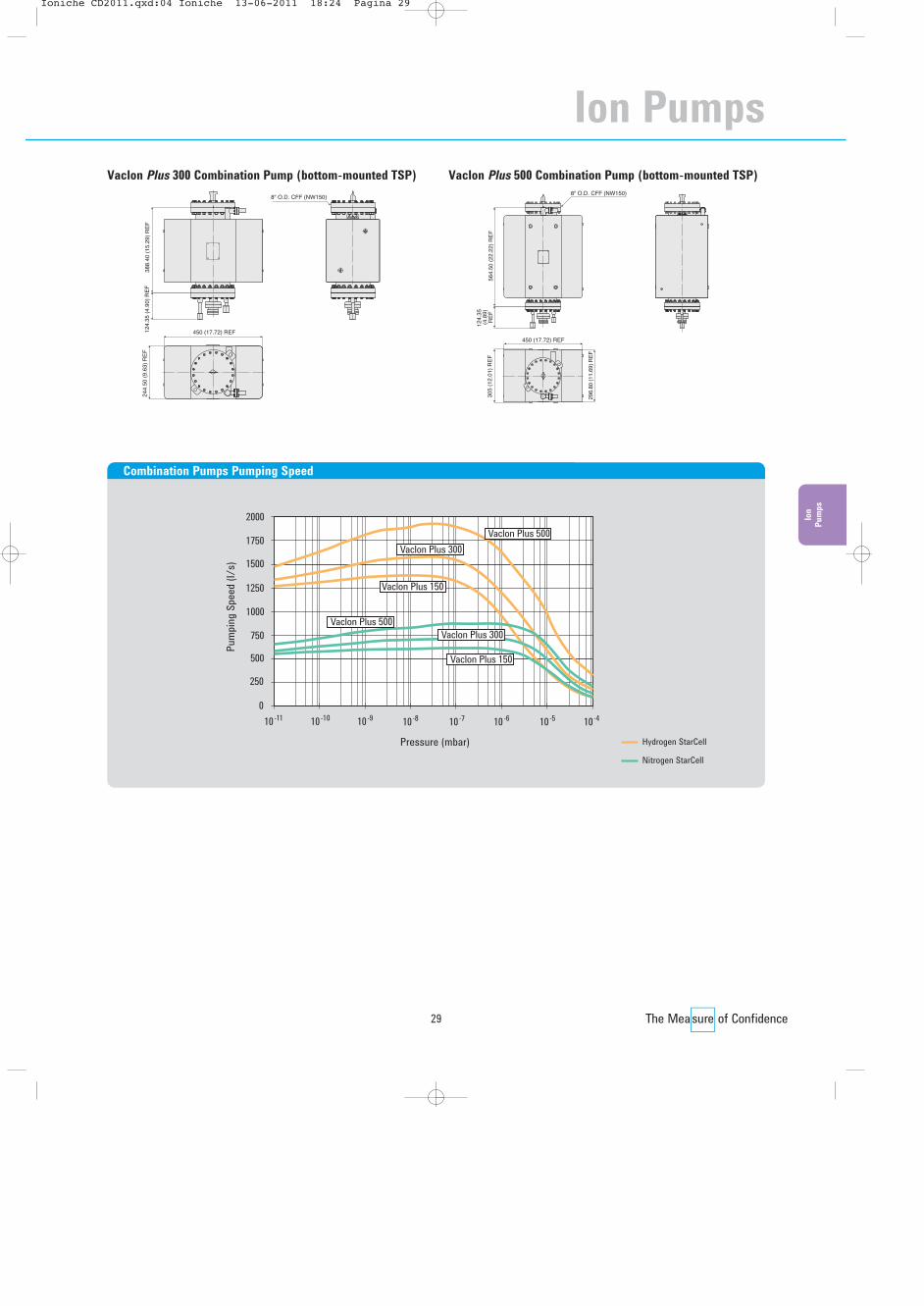
Pressure (mbar)
Pum
ping
Spee
d (l/
s) 1500
010-11 10-10 10-9 10-8
250
1750
1250
1000
2000
10-7 10-6 10-5 10-4
750
500 Vaclon Plus 150
Vaclon Plus 500Vaclon Plus 300
Vaclon Plus 150
Vaclon Plus 300Vaclon Plus 500
Combination Pumps Pumping Speed
244.
50 (
9.63
) R
EF
450 (17.72) REF124.
35 (
4.90
) R
EF
388.
40 (
15.2
9) R
EF
8" O.D. CFF (NW150)
Vaclon Plus 300 Combination Pump (bottom-mounted TSP)
564.
50 (
22.2
2) R
EF
124.
35
(4.8
9)R
EF
296.
80 (1
1.69
) RE
F
305
(12.
01)
RE
F
450 (17.72) REF
8" O.D. CFF (NW150)
Vaclon Plus 500 Combination Pump (bottom-mounted TSP)
Hydrogen StarCell
Nitrogen StarCell
Ion
Pum
ps
Ion Pumps
��������� ������� ����������� ��� ���������������

30
The VacIon Plus 500, 300, and 150 pumps can be supplied with the sublimation cryopanel factory-installed and TSP cartridgeincluded. Cables and controllers are to be ordered separately. For basic pump part number, see pages 22-27.
Description Part Number
Vaclon Plus 500, 300, or 150 combination pumpVacIon Plus 150 Diode, with Side-Mounted Cryopanel, with TSP Cartridge and with Installed Heater 120V 9192510VacIon Plus 150 Diode, with Side-Mounted Cryopanel, with TSP Cartridge and with Installed Heater 220V 9192511VacIon Plus 150 Noble Diode, with Side-Mounted Cryopanel, with TSP Cartridge and with Installed Heater 120V 9192520VacIon Plus 150 Noble Diode, with Side-Mounted Cryopanel, with TSP Cartridge and with Installed Heater 220V 9192521VacIon Plus 150 Starcell, with Side-Mounted Cryopanel, with TSP Cartridge and with Installed Heater 120V 9192540VacIon Plus 150 Starcell, with Side-Mounted Cryopanel, with TSP Cartridge and with Installed Heater 220V 9192541VacIon Plus 300 Diode, with Side-Mounted Cryopanel, with TSP Cartridge and with Installed Heater 120V 9192610VacIon Plus 300 Diode, with Side-Mounted Cryopanel, with TSP Cartridge and with Installed Heater 220V 9192611VacIon Plus 300 Noble Diode, with Side-Mounted Cryopanel, with TSP Cartridge and with Installed Heater 120V 9192620VacIon Plus 300 Noble Diode, with Side-Mounted Cryopanel, with TSP Cartridge and with Installed Heater 220V 9192621VacIon Plus 300 Starcell, with Side-Mounted Cryopanel, with TSP Cartridge and with Installed Heater 120V 9192640VacIon Plus 300 Starcell, with Side-Mounted Cryopanel, with TSP Cartridge and with Installed Heater 220V 9192641VacIon Plus 300 Diode, with Bottom-Mounted Cryopanel, with TSP Cartridge and with Installed Heater 120V 9192612VacIon Plus 300 Diode, with Bottom-Mounted Cryopanel, with TSP Cartridge and with Installed Heater 220V 9192613VacIon Plus 300 Noble Diode, with Bottom-Mounted Cryopanel, with TSP Cartridge and with Installed Heater 120V 9192622VacIon Plus 300 Noble Diode, with Bottom-Mounted Cryopanel, with TSP Cartridge and with Installed Heater 220V 9192623VacIon Plus 300 Starcell, with Bottom-Mounted Cryopanel, with TSP Cartridge and with Installed Heater 120V 9192642VacIon Plus 300 Starcell, with Bottom-Mounted Cryopanel, with TSP Cartridge and with Installed Heater 220V 9192643VacIon Plus 500 Diode, with Side-Mounted Cryopanel, with TSP Cartridge and with Installed Heater 120V 9192710VacIon Plus 500 Diode, with Side-Mounted Cryopanel, with TSP Cartridge and with Installed Heater 220V 9192711VacIon Plus 500 Noble Diode, with Side-Mounted Cryopanel, with TSP Cartridge and with Installed Heater 120V 9192720VacIon Plus 500 Noble Diode, with Side-Mounted Cryopanel, with TSP Cartridge and with Installed Heater 220V 9192721VacIon Plus 500 Starcell, with Side-Mounted Cryopanel, with TSP Cartridge and with Installed Heater 120V 9192740VacIon Plus 500 Starcell, with Side-Mounted Cryopanel, with TSP Cartridge and with Installed Heater 220V 9192741VacIon Plus 500 Diode, with Bottom-Mounted Cryopanel, with TSP Cartridge and with Installed Heater 120V 9192712VacIon Plus 500 Diode, with Bottom-Mounted Cryopanel, with TSP Cartridge and with Installed Heater 220V 9192713VacIon Plus 500 Noble Diode, with Bottom-Mounted Cryopanel, with TSP Cartridge and with Installed Heater 120V 9192722VacIon Plus 500 Noble Diode, with Bottom-Mounted Cryopanel, with TSP Cartridge and with Installed Heater 220V 9192723VacIon Plus 500 Starcell, with Bottom-Mounted Cryopanel, with TSP Cartridge and with Installed Heater 120V 9192742VacIon Plus 500 Starcell, with Bottom-Mounted Cryopanel, with TSP Cartridge and with Installed Heater 220V 9192743
Description Weight kg (lbs) Part Number
Replacement Parts and AccessoriesTSP Filament Cartridge on 2 ¾” CFF 2.7 (6.0) 9160050Replacement filaments, package of 12 each 0.4 (2.0) 9160051Titanium Sublimation Pump Control Unit (Order cables separately) 120V 17.7 (39.0) 9290022Titanium Sublimation Pump Control Unit (Order cables separately) 220V 17.7 (39.0) 9290023TSP Cartridge cable, 3.5 m (12 ft.) 9.1 (20.0) 9240730Sublimation Cryopanel on 8” CFF 10.5 (23.0) 9190180
Ordering Information
Agilent Ion Pump Models
Agilent VacIon PlusCombination Pumps
��������� ������� ����������� ��� ��������������

31
Agilent Ion Pump Controllers
Agilent Mini Vac Controller
Ion
Pum
ps
POLARITY
1V=1mAO
PUMP
CURRENT
OUTPUT
VOLTAGE
I
9
6
5
1
ACCESSORY
OUTPUT5000 VDC
J001
H.V.ON
2
3
4
5
5
mA1
2
4
3
8
6
7
10
9
kV
HIGHLOAD
MODEL
SERIAL
VOLT
made in Italyvarian Spa Lein
A Hz
Ï
120
122.
50 (
4.82
) R
EF
128.
50 (
5.06
) R
EF
91.40 (3.60) REF
106.40 (4.19) REF200 (7.87) REF
110.
50 (
4.35
) R
EF
Dimensions: millimeters (inches)
Input
90 to 130 VAC or 180 to 240 VAC or 24 VDCOutput
Voltage: ± 5000 VDC (open load)Current: 15 mA (short circuit)Maximum Power: 21 W (3 kV at 7 mA)Front Panel
HV ON, HIGH LOAD, and POLARITY LEDsLED bargraph linear scale for current and voltage indicationRecorder Output 0 to +10 VDC linear proportional to current (10 V = 10 mA)Safety Marks
CE, cCSAus
Conformity to Norms
Safety: EN61010-1EMI/EMC: EN61000-4-2, EN61000-4-3, EN61000-4-4Rear Panel
Nine pin “D” type connector with following available signals andcommands Recorder outputs:• 0 to +5 VDC, linear proportional to HV (1 V = 1 kV)• 0 to +10 VDC, linear proportional to current (10 V = 10 mA)• 0 to +10 VDC, linear proportional to current (10 V= 1 mA)HV ON confirm signal: Contact rating – 1 A at 250 VAC; 0.2 A at 30 VDCRemote HV ON/OFF (interlock) commandHV connector: Fischer type 105 or King type, 10 kV
Technical Specifications
The MiniVac Ion Pump Controller is designed to economicallyoperate any Vaclon Plus type and size: Diode, Noble Diode, andStarCell, from Miniature to 500 l/s pumps. The MiniVac is verycompact and light, can be operated in local or remote mode, andis suitable for high radiation environments.Medium pumps (Vaclon Plus 20 to 75) can be operated at anypressure below 1 x 10⁻⁵ mbar (continuous operation).
Large pumps (Vaclon Plus 150 to 500) can be operated at anypressure below 2 x 10⁻⁶ mbar (continuous operation).The MiniVac is designed to withstand continuous operation atshort circuit conditions, without damaging the ion pump oritself. A 24 V battery-operable version is available for portable applications.
Description Weight kg (Ibs) Part Number
MiniVac Controller
With any VacIon Plus pump MiniVac, FISCHER HV connector, US plug, 120 V preset 2.3 (5.0) 9290191MiniVac, FISCHER HV connector, European plug, 220 V preset 2.3 (5.0) 9290290MiniVac, FISCHER HV connector, 24 VDC 2.3 (5.0) 9290196
With small VacIon pumps (2 and 10 l/s) MiniVac, KING HV connector, US plug, 120 V preset 2.3 (5.0) 9290190MiniVac, KING HV connector, European plug, 220 V preset 2.3 (5.0) 9290291MiniVac, KING HV connector, 24 VDC 2.3 (5.0) 9290197
Accessories and Cables
19” Rack adapter 4.5 (10.0) 9699191With any VacIon Plus pump HV bakeable cable, radiation resistant, 4 m (13 ft.) long, with Interlock 0.9 (2.0) 9290705
HV bakeable cable, radiation resistant, 7 m (23 ft.) long, with Interlock 1.6 (3.5) 9290707HV bakeable cable, radiation resistant, 10 m (33 ft.) long, with Interlock 2.2 (5.0) 9290708HV bakeable cable, radiation resistant, 20 m (66 ft.) long, with Interlock 4.4 (10.0) 9290709
With small VacIon pumps (2 and 10 l/s) HV bakeable cable, radiation resistant, 4 m (13 ft.) long, with Interlock for 2 l/s pump 0.9 (2.0) 9290706HV cable, 3 m (10 ft.) long, for 8 l/s VacIon pumps 0.9 (2.0) 9240741
Ordering Information
Diode, Noble Diode positiveStarCell, Triode negative (see page 40)
Ion Pumps
��������� ������� ����������� ��� ���������������

32
How much power do I need for my ion pumps?
Power requirement depends on the pumpsize and starting pressure; the larger thepump and higher the starting pressure,the higher the power consumption. The largest standard Ion Pumpconfiguration, 500 l/s, can be easilystarted with 200W up to 1-5 mbar, while a medium size pump (75 l/s) needs lessthan 80 W to be started at the samepressure, and 80 W are sufficient to operate a 500 l/s in the typical IonPump operating range (below 2-6 mbar).
Why was the higher power ratingnecessary in the past?
In the past ion pumps were started withthe aid of sorption pumps, able to reach10-4 mbar only. As a consequence, muchlarger and more powerful Ion pumpscontroller were needed. The resulting lifeof Ion Pumps started at such highpressures was much shorter (1 minute ofoperation at 10-4 mbar is equivalent to 2months at 10-9 mbar) Today’s oil-freeturbo pumps, backed by oil-free primarypumps, achieve lower pressures, therebyreducing the starting pressure of the ionpump. This reduces the maximum powerrequirement of the ion pump controllerand extends the lifetime of the ion pump.
Negative or positive?
The requirement of negative or positivepotential depends on the pumpingelement installed in the ion pump. Diodestyle elements (Diode & Noble Diode)need positive voltages, while Triode styleelements (old style Triode & StarCell)need negative voltages for operation.
Agilent 4UHV Ion Pump Controller
Agilent Ion Pump Controllers
��������� ������� ����������� ��� ���������������

Ion
Pum
ps
33
211.40 (8,32) 199.60 (7,86)141.20 (5,56)
177.
00 (
6,97
)
164.
30 (
6,47
)
400.50 (15,77)
Dimensions: millimeters (inches)
Description Part Number
4UHV Controller
120 W negative 9299100 120 W positive 9299101 200 W neg 9299010 200 W pos 9299011 2 x 80 W neg 9299200 2 x 80 W pos 9299201 2 x 200 W neg 9299020 2 x 200 W pos 92990211 x 200 W pos & 1 x 200 W neg 9299022 4 x 80 W neg 9299400 4 x 80 W pos 92994012 x 80 W pos & 2 x 80 W neg 9299402 2 x 80 W neg & 1 x 200 W neg 9299210 2 x 80 W pos & 1 x 200 W pos 92992112 x 80 W pos & 1 x 200 W neg 92992122 x 80 W neg & 1 x 200 W pos 9299213
Description Part Number
Accessories and Cables *HV Bakeable cable, radiation resistant, 4 m (13 ft.) long, with interlock 9290705HV Bakeable cable, radiation resistant, 7 m (23 ft.) long, with interlock 9290707HV Bakeable cable, radiation resistant, 10 m (33 ft.) long, with interlock 9290708HV Bakeable cable, radiation resistant, 20 m (66 ft.) long, with interlock 9290709Rack adapter 19” 9290064Mains cable NEMA Plug, 3 m (10 ft.) long 9699958 Mains cable European Plug, 3 m (10 ft.) long 9699957 (*) The unit does not include the power cable, please order the cable
separately.
Ordering Information
Input voltage 100 - 240 Vac (+/-10%)Input frequency 50/60 HzDimensions 400.5 x 211.4 x 177.0 mm (l x w x h)Display 4 rows with 20 charactersAvailable configurations 1 x 120 W, 1 x 200 W, 2 x 80 W,
2 x 200 W, 4 x 80 W, 2 x 80 W +1 x 200 WMinimum Configuration One HV card with 120W, 200W or 2x80WOutput voltage (Open Circuit) 3.5 and 7 kVOutput current (Short Circuit) 40 mA for 80 W channel,
100 mA for 200 W channel
Modes of operation Local / Serial / RemoteFront panel readings Voltage, Pressure, Current, StatusSafety marks CE, C_CSA_USCurrent measurement range 10 nA to 100 mAInput signals On/off; Protect; Step Mode; Output signals Analog Out; NC Set-point; NO Set-pointHV connector Fischer Type 105Output Power Maximum 400 WCommunications RS232/485 standard
Profibus or Ethernet optional
Technical Specifications
Ion Pumps
��������� ������� ����������� ��� ���������������

34
Agilent Ion Pump Models
Agilent Miniature and Small
VacIon Pumps and Controllers
Ordering Information
See page 31 for controllers, cables, and accessories.
Description Weight kg (lbs) Part Number
Miniature PumpWith ⅜” OD 180° stainless steel tube 0.5 (1.0) 9130038With ⅜” OD 90° stainless steel tube 0.5 (1.0) 9130041With ⅜” OD 180° copper tube, vacuum processed 0.5 (1.0) 9130049With ⅜” OD 90° copper tube, vacuum processed 0.5 (1.0) 9130050Magnet for Miniature pump 0.5 (1.0) 9130042HV cable, 2.4 m (8 ft.) long, for Mini VacIon pumps 0.9 (2.0) 9240122
2 l/s Pump
With ¾” OD 180° stainless steel tube 0.9 (2.0) 9190521With ¾“ OD 180° copper tube, vacuum processed 0.9 (2.0) 9190522With ¾” OD 180° stainless steel tube, vacuum processed 0.9 (2.0) 9190523With ¾” OD 90° stainless steel tube, tee style 0.9 (2.0) 9190524With 1 1/3” CFF 180° vacuum processed 0.9 (2.0) 9190520Magnet for 2 l/s pump 0.9 (2.0) 9190038HV bakeable cable, radiation resistant, 4 m (13 ft.) long with interlock for 2 l/s pump 0.9 (2.0) 9290706
10 l/s Pump
10 l/s Vaclon pump, processed, with 2 ¾” CFF 3.6 (8.0) 9195005Magnet assembly for 10 l/s Vaclon pump 5.0 (11.0) 9110030HV cable, 3 m (10 ft.) long, for 10 l/s VacIon pumps 0.9 (2.0) 9240741Magnets must be ordered separately.
Agilent offers a wide variety of small size ion pumps designedespecially for electron device and detector applications. TheMiniature Vaclon pump is a diode configuration and providesapproximately 0.4 l/s of nitrogen pumping speed. The 2 l/smodel is a modified diode configuration to enhance starting at low pressure. The 10 l/s pump is a noble gas optimizeddiode configuration with high efficiency for residual gasessuch as hydrogen. The pumping speed for noble gases isabout 20% of the nominal speed. Pumps that are processed are baked to 400 °C and pinched
off under vacuum, which allows the vacuum integrity to beverified by the user just before use. Non-processed pumpsare tested for no vacuum leaks and minimum leakage current.Modified and Customized Versions
Modified versions of standard pumps can be provided whendiffer ent inlet tube lengths, angles, and diameters arerequired. These pumps can also be customized with differenthigh voltage feed throughs, body geometries, and pumping cellarrangements. Special testing procedures can be quoted forcustomers who have specific requirements in this area.
��������� ������� ����������� ��� ���������������

35
The Miniature and 2 l/s pumps are available with copper orstainless steel inlet tubes in 90- or 180-degree configurations,relative to the high voltage feedthrough.
54.1 (2.1) REF
31.8
(1.
3) R
EF
42.9 (1.7) REF
19.1 (0.8) REF
PROCESSED)(VACUUM
27.2 (1.1) REF
25.7 (1.0) REF
20.1 (0.8) REF
Ø 9
.4 (
0.4)
RE
F
Ø 24.
9 (1
.0) R
EF
APPROX.PINCH OFF
63.0 (2.5) REF
70.1 (2.8) REF
Miniature Pump (180 deg. config.)
Ø 9
.5 (
0.37
) R
EF
43.0 (1.69) REF 20.0 (.79) REF 54.0 (2.13) REF
54.0
(2.
13)
RE
F
25.0 (.98) REF
21.0 (.83) REFØ 25.0 (0.98) REF
27.0
(1.
06)
RE
F
Miniature Pump (90 deg. config.)
2 3/4" O.D. CFF (NW35)
133.00 (5.24) REF
206.00 (8.11) REF
153.
00 (
6.70
) R
EF
78.70 (3.04) REF
95.00 (3.70) REF
10 l/s Pump
Dimensions: millimeters (inches)
55.673 (2.2)
35.800 (1.4)
32.173 (1.3)
40.000 (1.6)
40.000 (1.6)
111.705 (4.4)
Ø 1
9.50
0 (0
.8)
40.000 (1.6)46.000 (1.8)
30.2
00 (
1.2)
60.4
00 (
2.4)
2 l/s Pump
Ion
Pum
ps
Ion Pumps
��������� ������� ����������� ��� ���������������

36
Agilent Titanium Sublimation Pumps and Controllers
Technical Specifications
Usable titanium (per filament) 1.1 gramsTotal usable 3.3 gramsOperating range 10-4 to 10-12 mbar
Titanium sublimation pumps (TSPs) are typically used as aneffective way to pump getterable gases such as hydrogen andnitrogen in UHV systems. TSPs are often combined with ionpumping, since the ion pump is effective with non-get terableUHV gases such as argon and methane. The TSP can be addedto the inside of the ion pump, or as a separate pumping unit. Ifthe TSP is used in conjunction with a liquid nitrogen-cooledcryo panel, extra high water pumping speed will be achieved.Agilent offers two different types of titanium sublimationpumps: filament and titanium ball sources. Filament-type TSPsources are most popular with UHV systems since they canbe turned off between sublimations and thus do not addthermally-induced outgassing. The ball-type sources containlarger amounts of titanium which means longer life whenoperated under conditions that use more titanium, such ashigher operating pressures. However, the ball sources requirestandby power between sublimations to prevent cracks fromforming in the titanium ball.The factors affecting titanium sublimation pumping efficiencyinclude sublimation rate, frequency, surface area, andtemperature. Sublimation pumping speed is generally aconstant value below 10-7 mbar.
FILAMENTSUBLIMATION3 TITANIUM
STAINLESS STEELGROUND ROD
2 " O.D. CFF(NW35)
3/4
130.4 (5.13) REF
281.9 (11.10) REF
324.3 (12.77) REF
TSP Cartridge
TSP Cartridge Filament Source
The popular TSP cartridge is provided on a 2 ¾” OD ConFlatflange and contains three titanium-molybdenum filaments,each with 1.1 grams of usable titanium. The cartridgeassembly is bakeable to 400 °C. Maximum sublimation isachieved at 300 watts of source power.
Technical Specifications
Usable titanium 15.2 gramsOperating range 10-4 to 10-12 mbar
41.1 (1.62) REF185.6 (7.31) REF
61.4 (2.42) REF
SOURCE ASSEMBLYMINI TI-BALL
21.3
(.8
4) R
EF
MINI TI-BALLSOURCE HOLDER
2 " O.D. CFF(NW35)
3/4
Mini Ti-Ball
Mini Ti-Ball Source
The Mini Ti-Ball source provides 15.2 grams of usabletitanium and is mounted on a 2 ¾” OD ConFlat flange.Maximum sublimation is achieved at 300 watts of sourcepower, while the Standby power requirement is 100 watts.
Dimensions: millimeters (inches)
Dimensions: millimeters (inches)
��������� ������� ����������� ��� ���������������

37
Ion
Pum
ps
Dimensions: millimeters (inches)
TSP Cryopanel
Designed for use with the TSP cartridge source*, thissublimation cryopanel is mounted to an 8” OD ConFlat flange.It can operate with water cooling, liquid nitrogen, or uncooledif used at UHV. This cryopanel can be mounted to double-ended or side-ported ion pumps and can also be usedindependently in any 8” (NW 150) CFF port with 11 inchdepth/clearance.The Cryopanel does not include the cartridge.
124.3 (4.89) REF276.6 (10.89) REF
120.
0 (4
.72)
RE
F
8" O.D. CFF (NW150)
Ø 1
40.0
(5.
51)
Technical Specifications
N2 H2 H20
Pumping speed at 20 °C water-cooled (l/s) 515 1200 575Inner pumping surface (cm2) 826Main flange 8” CF (NW150)Reservoir volume (liters) 1.8Cooling connection ⅜” GTitanium source flange 2 ¾” CF
1000
010-11 10-10 10-9 10-8
250
1250
10-7 10-6 10-5 10-4
Pressure (mbar)
Pum
ping
Spee
d (l/
s)
750
500
0,01 gr/h
0,1 gr/hH2
H2O
N2
Pumping Speed vs Pressure at different evaporation rates
Agilent TSP Cryopanel
Ion Pumps
��������� ������� ����������� ��� ���������������
38
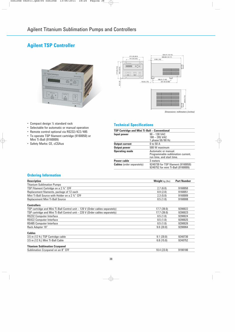
Agilent TSP Controller
177.
04 (
7.0)
164.
3 (6
.5)
6.0
(.3)
141.22 (5.6)
211.33 (8.3)334.01 (13.15)
308.99 (12.17)
3.99 (.16)
188.01 (7.40)251.00 (9.88)19.00 (.75)
200.
0 (7
.9)
• Compact design ½ standard rack• Selectable for automatic or manual operation• Remote control optional via RS232/422/485• To operate TSP filament cartridge (9160050) or
Mini Ti-Ball (9160009)• Safety Marks: CE, cCSAus
Dimensions: millimeters (inches)
Technical Specifications
TSP Cartridge and Mini Ti-Ball – Conventional
Input power 90 – 130 VAC180 – 265 VAC1 phase 50/60 Hz
Output current 0 to 50 AOutput power 500 W maximumOperating mode Automatic or manual.
Programmable sublimation current,run time, and start time.
Power cable 3 metersCables (order separately) 9240730 for TSP filament (9160050)
9240752 for mini Ti-Ball (9160009)
Ordering Information
Description Weight kg (lbs) Part Number
Titanium Sublimation PumpsTSP Filament Cartridge on a 2 ¾” CFF 2.7 (6.0) 9160050Replacement filaments, package of 12 each 0.9 (2.0) 9160051Mini Ti-Ball Source with Holder on a 2 ¾” CFF 2.3 (5.0) 9160009Replacement Mini Ti-Ball Source 0.5 (1.0) 9160008
Controllers
TSP cartridge and Mini Ti-Ball Control unit – 120 V (Order cables separately) 17.7 (39.0) 9290022TSP cartridge and Mini Ti-Ball Control unit – 220 V (Order cables separately) 17.7 (39.0) 9290023RS232 Computer Interface 0.5 (1.0) 9290024RS422 Computer Interface 0.5 (1.0) 9290025RS485 Computer Interface 0.5 (1.0) 9290026Rack Adapter 19” 9.0 (20.0) 9290064
Cables
3.5 m (12 ft.) TSP Cartridge cable 9.1 (20.0) 92407303.5 m (12 ft.) Mini Ti-Ball Cable 6.8 (15.0) 9240752
Titanium Sublimation Cryopanel
Sublimation Cryopanel on an 8” CFF 10.4 (23.0) 9190180
Agilent Titanium Sublimation Pumps and Controllers
��������� ������� ����������� ��� ���������������

39
Agilent Ion Pump Technical Notes
Historical Notes
Ion pumping is used to remove gases from systems in orderto create ultra-high vacuum environments. The earliestevidence of ion pumping was reported by J. Plucker (1858 - Germany) who found that it took ever-increasingvoltages to maintain a current in a gas discharge tube.This, he rightly concluded, is due to a reduction of pressure inthe tube by some mechanism involving the cathode.Later, as an offshoot of his work on electrical discharge ingases, F. Penning (1937 - Holland) developed a cold cathodeionization gauge for measuring pressures in the range of 10-3
to 10-5 Torr. Due to the sputtering effect of the high voltage,ions were both buried in and “gettered” by the cathodematerial. (Gettering is the chemical combination of activegases with a suitably reactive substance).The result of this pumping action was a noticeable pressurereduction. The Penning cell has been used as a commerciallyavailable vacuum gauge ever since, but it was not until thelate 1950's that its pumping characteristics were exploited byAgilent Associates, resulting in the invention of the ion pump.This was done in order to improve the life and performance ofmicrowave tubes by continuous pumping with “appendage”ion pumps.The invention of the sputter ion pump ushered in the era ofultrahigh vacuum, just in time to make a large contribution tothe space age.The availability of vacuum systems that could routinelyachieve pressures in the low 10-11 Torr range enhanced R&Defforts. Space hardware and space-compatible materials weretested by simulating many of the conditions they wouldencounter. Today, ion pumps are used in both research andindustrial applications wherever a pristine, oil-free, vibration-free, cost-effective environment is required.
Operation
Vacuum pumps in general operate on the basis of maintaininga lower gas density within themselves than exists in theenvironment they are pumping. This results in a net gasmigration into the pump due to the random motion of themolecules under molecular flow conditions. Once in thepumps, few escape and they are either displaced or captured,depending on the type of pump.Rather than being a displacement pump that actually movesmolecules of gas through it to the atmosphere, the ion pumpinstead captures and stores them. As a result, at some pointin time the pump must be reconditioned or replaced. This isgenerally required only after many years of use.The generic name Sputter Ion Pump (or Ion Getter Pump)comes from the fact that some of the gas molecules undergoionization and cause sputtering of the gettering agent. Thismaterial chemically reacts with the active gases to formstable compounds that are deposited on the internal walls ofthe pump. The getter, usually titanium, is provided by a plateor electrode of that material, which is in turn sputtered and
eroded by gas ions formed under the influence of the highvoltage. These electrical potentials are usually in the range of3,000 to 7,000 Vdc.Most ionization devices operate in the same way. Gasmolecules are bombarded by high energy electrons when acollision occurs. A molecule may lose one or more of its ownelectrons and thereby is left as a positively charged ion. Underthe influence of a strong electric field, the ion is acceleratedinto the titanium cathode. The force of this collision issufficient to cause atoms to be ejected from the cathode and“sputtered” onto the adjacent walls of the pump. Freshlysputtered titanium is extremely reactive and will chemicallyreact with active gases. The resulting compounds accumulateon surfaces of the pump elements and pump walls.Active gases are those such as oxygen, nitrogen, CO, CO2,and water, as opposed to the noble gases like helium, neon,argon, krypton, and xenon, which are nonreactive. The latterare pumped by “ion burial” (ion burial is the “plastering over”of inert gas atoms by the sputtered getter atoms).The simplest form of ion pump is the Penning cell, which wasoriginally conceived as a cold cathode vacuum gauge. Itconsists of a central anode wire which is at positive highvoltage. In an ion pump the anode can either be a shortsection of metal tubing or a square, box-like structure, openat each end like a unit of an egg crate. Opposite each openend is a plate of titanium that is connected to the ground toform the cathode structure. An external permanent magneticcircuit generates a magnetic field, usually ranging from 800 to2,000 G, parallel to the anode cell axis. A cell configured inthis way is said to be a diode pump (Figure 1). It is thenpackaged in a suitable enclosure and the assembly becomesa pump.To make a higher speed pump, it is now simply a matter ofmaking a package containing more cells with a larger cathode(Figure 2).The function of the anode cell structure is to contain a“cloud” of high energy electrons which are constrained by themagnetic field. This field causes the electrons to move in oscillating spiralpaths (Figure 3) that increase their chances of striking gasmolecules and thereby create positive ions. These ions areaccelerated away from the positive anode voltage and collideinto the titanium cathode plates (Figure 3). This results in theremoval of titanium atoms by “sputtering”.The sputtered titanium is deposited on the internal surfacesof the pump where it reacts with absorbed active gases toform stable compounds.In summary, the pumping efficiency depends on the electron“cloud” density (which determines the number of ionsproduced) and on the sputtering yield (which determines the quantity of active getter material produced).The electron cloud density mainly depends on the Penningcell geometry and on the electric and magnetic fieldstrengths. By adjusting these parameters, the pumpperformance can be modified according to the application.In particular, using an “intelligent” high voltage power supply,
Ion
Pum
ps
Ion Pumps
��������� ������� ����������� ��� ���������������

40
Agilent Ion Pump Technical Notes
Figure 1
Figure 2
Figure 3
Figure 4
Figure 5
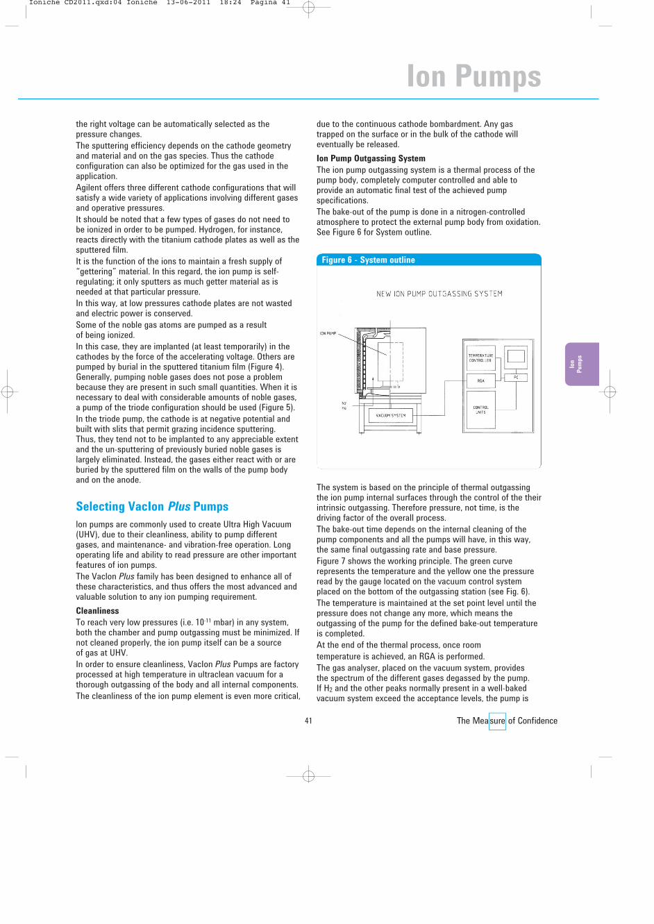
Ion pump cutaway
��������� ������� ����������� ��� ��������������
41
the right voltage can be automatically selected as thepressure changes.The sputtering efficiency depends on the cathode geometryand material and on the gas species. Thus the cathodeconfiguration can also be optimized for the gas used in theapplication.Agilent offers three different cathode configurations that willsatisfy a wide variety of applications involving different gasesand operative pressures.It should be noted that a few types of gases do not need tobe ionized in order to be pumped. Hydrogen, for instance,reacts directly with the titanium cathode plates as well as thesputtered film.It is the function of the ions to maintain a fresh supply of“gettering” material. In this regard, the ion pump is self-regulating; it only sputters as much getter material as isneeded at that particular pressure.In this way, at low pressures cathode plates are not wastedand electric power is conserved.Some of the noble gas atoms are pumped as a resultof being ionized. In this case, they are implanted (at least temporarily) in thecathodes by the force of the accelerating voltage. Others arepumped by burial in the sputtered titanium film (Figure 4).Generally, pumping noble gases does not pose a problembecause they are present in such small quantities. When it isnecessary to deal with considerable amounts of noble gases,a pump of the triode configuration should be used (Figure 5).In the triode pump, the cathode is at negative potential andbuilt with slits that permit grazing incidence sputtering. Thus, they tend not to be implanted to any appreciable extentand the un-sputtering of previously buried noble gases islargely eliminated. Instead, the gases either react with or areburied by the sputtered film on the walls of the pump bodyand on the anode.
Selecting VacIon Plus Pumps
lon pumps are commonly used to create Ultra High Vacuum(UHV), due to their cleanliness, ability to pump differentgases, and maintenance- and vibration-free operation. Longoperating life and ability to read pressure are other importantfeatures of ion pumps.The Vaclon Plus family has been designed to enhance all ofthese characteristics, and thus offers the most advanced andvaluable solution to any ion pumping requirement.Cleanliness
To reach very low pressures (i.e. 10-11 mbar) in any system,both the chamber and pump outgassing must be minimized. Ifnot cleaned properly, the ion pump itself can be a source of gas at UHV.In order to ensure cleanliness, VacIon Plus Pumps are factoryprocessed at high temperature in ultraclean vacuum for athorough outgassing of the body and all internal components.The cleanliness of the ion pump element is even more critical,
due to the continuous cathode bombardment. Any gastrapped on the surface or in the bulk of the cathode willeventually be released.Ion Pump Outgassing System
The ion pump outgassing system is a thermal process of thepump body, completely computer controlled and able toprovide an automatic final test of the achieved pumpspecifications.The bake-out of the pump is done in a nitrogen-controlledatmosphere to protect the external pump body from oxidation.See Figure 6 for System outline.
The system is based on the principle of thermal outgassingthe ion pump internal surfaces through the control of the theirintrinsic outgassing. Therefore pressure, not time, is thedriving factor of the overall process. The bake-out time depends on the internal cleaning of thepump components and all the pumps will have, in this way,the same final outgassing rate and base pressure.Figure 7 shows the working principle. The green curverepresents the temperature and the yellow one the pressureread by the gauge located on the vacuum control systemplaced on the bottom of the outgassing station (see Fig. 6).The temperature is maintained at the set point level until thepressure does not change any more, which means theoutgassing of the pump for the defined bake-out temperatureis completed. At the end of the thermal process, once roomtemperature is achieved, an RGA is performed.The gas analyser, placed on the vacuum system, provides the spectrum of the different gases degassed by the pump. If H2 and the other peaks normally present in a well-bakedvacuum system exceed the acceptance levels, the pump is
Figure 6 - System outline
Ion
Pum
ps
Ion Pumps
��������� ������� ����������� ��� ���������������

42
Agilent Ion Pump Technical Notes
baked again. Otherwise, it is pinched off and its base pressuremonitored. The base pressure is evaluated through the ioncurrent reading.The current decrease is computer monitored, and the pump isready to be shipped only after the base current is reached.Figure 8 shows the result of the residual gas analysisperformed at the end of the bake-out.Pumping of Different Gases
In general, all ion pumps can pump all gases to somedegree. To obtain the best performance and base pressure,different types of ion pumps have been developed withoptimized performance in different pressure ranges and withdifferent gases.
Agilent's VacIon Plus is a complete product family that offersthe choice among three different elements: Diode, NobleDiode and StarCell.Whatever the application, there is a VacIon Plus pumpdesigned for it.
Long Operating Life
All VacIon Plus pumps have rated lives in excess of manythousand of hours at a pressure of 1x10⁻⁶ mbar (50,000 hoursfor the Diode pump, and 80,000 hours for the StarCell).With many ion pumps, maintenance may be required wellbefore the rated life, due to metallization of insulators orpumping element distortion.All VacIon Plus elements are designed to minimize cathodedistortion (even after repetitive bake-outs and starting at highpressure), and the insulators are protected from sputteredtitanium by using a double re-entrant design and a cap shield.Pressure Reading
The ability to read pressures using an ion pump is due to thedirect proportionality between pump current and operatingpressure.The reliability of pressure readings at very low pressure islimited by leakage current, and the leakage current fromfield emission is heavily dependent on the voltage applied to the pump.The Dual controller, designed for use with any VacIon Pluspump, provides the unique ability to adjust the voltage inaccordance with the operating pressure. By doing this, theleakage current is minimized at low pressure, providing areliable pressure reading down to the 10-10 mbar range.Custom Design and Flexibility
All ion pumps can be mounted in any position, and do notneed any isolation valve from the system in case of venting orpower failure.VacIon Plus pumps are the most compact ion pumps in eachspeed range. The pumps can be configured with additionalflanges and can accomodate other pumping systems (likeTSP), allowing the best use of available space.Agilent Feedthrough
The whole Ion Pump line is provided with aninnovative feedthrough.The improved feedthrough of the ion pump line is a majorbreakthrough. The greatest advantages of the ion pumps arelisted here below:• Corrosion Free
The design of the feedthrough will reduce drastically thecorrosion that may occur when the pump is used inhumid environments.Our tests and experience have demonstrated that thecorrosion starts and increases with the presence of humiditybetween feedthrough and connector. The high voltageduring the pump operation ionizes the entrapped watervapor; the ions react with the brazing alloy and corrode it.The design of the feedthrough aims to solve these issues:– On one hand the design structure of the feedthrough
presents a negligible quantity of air.– On the other hand, the brazing is done on the vacuum side
so that the brazing alloy surface exposed to air is minimal.
Figure 7 - Thermal process working principle
Figure 8 - Residual gas analysis
��������� ������� ����������� ��� ���������������

43
• High Voltage Cable Interlock
The feedthrough has been designed for the “HV cable safetyinterlock” implementation. This feature avoids any electricalshock since the voltage is automatically cut off as soon asthe cable is disconnected from the pump.Our Ion Pump control unit (Dual) and the HV cable arealready able to support this safety feature when connectedto an ion pump with the feedthrough.
• Easy Connection
The connection of the cable connector to the feedthroughrequires simply inserting and pushing the connector. No use of retention screws is required.
• Safety against Unintentional Extraction
When the HV cable connector is inserted into the newpatented feedthrough, it is firmly and mechanically securedto it. A latch on the cable prevents disconnection.
• Compactness
The feedthrough design allows a significant gain of spacefor the customer.
The VacIon Plus Family
Diode Vaclon PlusThe diode version of the Vaclon Plus pump has the highestpumping speed among all ion pumps for oxygen (O2), nitrogen(N2), carbon dioxide (CO2), carbon monoxide (CO), and anyother getterable gas. It provides the highest pumping speedand capacity for hydrogen (H2) as well.Its simple mechanical structure allows a reliablecurrent/pressure reading down to very low pressures, as wellas absolutely vibration-free operation. Its geometric andelectrical configuration allows it to be used in the vicinity ofelectron detectors or similar devices.Diode Vaclon Plus pumps are therefore widely andsuccessfully used in general purpose UHV systems, forevacuating electron devices and in the most sensitiveelectron microscopes. However, diodes are not suggested forapplications where noble gases such as argon (Ar), helium(He), and methane (CH4) are to be pumped.Noble Diode Vaclon PlusThe Noble Diode Vaclon Plus element is a version of thediode element, in which a tantalum cathode is substituted inplace of a titanium cathode. This substitution allows a higherpumping speed and stability for pumping noble gases (mainlyargon and helium).The element is otherwise equivalent to the Diode Vaclon Plus.Noble Diode Vaclon Plus pumps are used in any applicationwhere pumping of noble gases is an important characteristic.As with the diode configuration, the Noble Diode retains aconsistent pumping speed for all gases at very low pressures.However, pumping speed for H2 and getterable gases is lowerthan for the corresponding Diode. The Noble Diode VaclonPlus is typically used in UHV applications where a mixture ofgas is to be pumped and where the pressure is quite constant
(i.e., no sudden gas burst or systematic high pressure cycling).Its characteristics of consistent speed for almost any gaseven at very low pressures make it ideal whenever the ionpump alone is used to obtain UHV pressures. This is often thesituation in particle accelerators or synchrotron rings, as wellas in surface analysis applications.Other Vaclon Plus versions are suggested whenever theapplication requires cycling to higher pressures, pumping oflarge amounts of H2, or when the ion pump is combined withother UHV pumps such as Titanium Sublimation Pumps orNon-Evaporable Getters.StarCell Vaclon PlusThe StarCell Vaclon Plus element is the latest variation of theTriode configuration. Its patented design makes this ion pumpthe only one that can handle a high amount of noble gases(better than Noble Diode) and hydrogen (comparable to theDiode). Furthermore, this pump provides the highest speedand capacity for methane, argon, and helium. Its high totalcapacity for all the different gases, together with its very goodspeed performance at relatively higher pressures, makes theStarCell Vaclon Plus ideal for applications requiring constantoperation at 10-8 mbar or above. This typically includesElectron Microscopes and Mass Spectrometers.
Its high pumping speed for argon, helium, and methane (thehighest of any ion pump at any pressure) has made StarCellthe standard for any application where the ion pump is usedin combination with TSP or NEG pumps, where its pumpingperformance is enhanced. The lowest attainable pressurehas been obtained with combinations of StarCell Vaclon Plusand TSP/NEG pumps, thanks to the optimizedcharacteristics of these combinations. Most existing particleaccelerators and synchrotron sources, beam lines, transferlines, and similar devices have used and are successfullyusing these combinations to obtain the maximum speed forall the gas species.For more specific information regarding the pumping speedsfor different element configurations relevant to differentgases, refer to the various curves published in the VaclonPlus Pumping Speed section. The aim of this section is to
Figure 9 - StarCell pumping element
Ion
Pum
ps
Ion Pumps
��������� ������� ����������� ��� ���������������

44
Agilent Ion Pump Technical Notes
help you choose the best Vaclon Plus configuration.Whatever the application, there is a Vaclon Plus versionsuited for it.Do not hesitate to contact your local Agilent representative ifyou need more assistance in making the right choice.For VacIon Plus and NEG integrated pumps, please ask Agilent for a special quotation.
VacIon Plus Pumping Speed
The most common parameter used to express the capabilityof a pump to remove molecules from a given volume ispumping speed. It is usually measured in liters per secondand expresses the volume of gas (at a given pressure)removed per time unit.In an ion pump, the net pumping effect results from the sumof different phenomena:• The pumping action of the getter film produced by the
sputtering of cathode material by ion bombardment.• The pumping action due to the ion implantation and
diffusion into the cathode.• Gas burial on the anodes and pump walls.• The gas re-emission from the cathode due to cathode
heating and erosion.When an ion pump is new or has been regenerated, forexample by baking, the surface layer of the cathode is cleanand the gas re-emission from it is negligible. In this condition,the ion pump is called “unsaturated” and the pumping effectis due both to the gettering effect as well as to ionimplantation and diffusion. As the number of gas moleculesimplanted into the cathode increases, the re-emission of themdue to the ion bombardment increases.As a consequence, the net pumping speed decreases until anequilibrium condition between ion implantation and gas re-emission is reached. In this condition, the ion pump is“saturated” and the net pumping speed, due only to thegettering action of the material sputtered from the cathode, isabout half the pumping speed of the unsaturated pump.Since the saturation effect depends on the quantity of gasmolecules implanted into the cathode, the time required tosaturate an ion pump is inversely proportional to thepressure at which the pump is operated. Thus, the lower thepressure, the longer the time before the pump saturationoccurs (Figure 10).In an ion pumped UHV system with a proper bakeoutprocedure (and consequent pump regeneration), a pressure inthe 10-11 mbar range is possible. At this pressure, the ionpump will work at the higher (unsaturated) pumping speedvalues for a few years before it is saturated.When pump saturation is reached, the pumping speed isconstant and no longer depends on the quantity of pumpedgas. The values of the pumping speed curve after saturationare the lowest obtainable at any given pressure.
Generally, the ion pump works in an intermediate conditionbetween the unsaturated and saturated extremes. The“nominal” pumping speed is defined as the maximum pointon the pumping speed curve for a saturated pump; thereference gas is usually nitrogen.The nominal pumping speed thus defines only a part of thecharacteristics of an ion pump. A more comprehensivedescription of an ion pump performance is given by thecomplete pumping speed vs pressure curve. By using theseplots and keeping in mind the application, the best pump can be chosen.
Active Gases (N2, 02, CO, CO2,…)
A characteristic of these gases is their ability to easily reactwith most metals forming stable compounds. In an ion pump,these active gas molecules react with the fresh titanium filmproduced by the sputtering of the cathode material. Theseactive gas molecules do not diffuse deeply in the cathode.The saturation effect, due to the re-emission of thesemolecules trapped on the cathode surface, is very strong.Diode and Noble Diode elements show a higher pumpingspeed at low pressure while StarCell elements perform betterat higher pressure, because the Penning discharge is betterconfined inside the element (Figures 11, 12).
Pressure (mbar)
% o
f Nom
inal
Pum
ping
Spee
d
110 -11
200
100
70 cm di a
40 cm di a
1O Y
10-10 10-9 10-8 10-7 10-6 10-5 10-4
1 Y
1 M1 d
1 h
1 min
Figure 10 - Saturation effect
��������� ������� ����������� ��� ���������������

45
Hydrogen
Hydrogen is an active gas but, due to its very small mass, the sputtering rate is very low. In spite of this fact, thepumping speed for H2 is very high because it quickly diffusesinto the cathode with negligible re-emission. When pumpingH2, the ion pump always works in the unsaturated condition. As a result, the nominal speed for H2 is about twice thecorresponding value for nitrogen.Furthermore, if some traces of heavier gases are present, theincreased sputtering rate produces an even higher hydrogenpumping speed.The Diode element shows a higher pumping speed than theNoble Diode since the H2 solubility in the tantalum cathode islower than in a titanium cathode. StarCell elements combinegood performance at higher pressures with enhancedcapacity for H2.
Noble Gases (He, Ne, Ar,…)
The main characteristic of noble gases is that they do notreact with any other element. Therefore, the film produced bythe sputtering of cathode material does not provide getterpumping for helium and argon. Moreover, since these gasesdo not tend to diffuse into the cathode, the pumping effectdue to the ion implantation is not permanent. Nevertheless, all the ion pump elements have some capacityto remove these gases.
Noble gases are pumped by being buried by titanium. Noblegas ions can be neutralized and scattered from the cathodewithout losing their energy. These neutral atoms maintainenough energy to implant or stick on the anode and on thepump walls where they will be buried by sputtered titaniumand thus permanently pumped.
% o
f Nom
inal
Spee
d
Pressure (mbar)
0
100
50
10-11 10-10 10-9 10-8 10-7 10-6 10-5 10-4
150
200
Figure 11 - Nitrogen pumping speed before saturation
Diode Noble Diode StarCell
% o
f Nom
inal
Spee
d
Pressure (mbar)
0
100
50
10-11 10-10 10-9 10-8 10-7 10-6 10-5 10-4
Figure 12 - Nitrogen pumping speed after saturation
Diode Noble Diode StarCell
% o
f Nom
inal
Spee
d
Pressure (mbar)
0
250
10-11 10-10 10-9 10-8 10-7 10-6 10-5 10-4
200
150
50
100
Figure 13 - Hydrogen pumping speed
Diode StarCell
% o
f Nom
inal
Spee
d
Pressure (mbar)
0
40
10-11 10-10 10-9 10-8 10-7 10-6 10-5 10-4
30
20
10
Figure 14 - Argon and Helium pumping speed
StarCell, Unsat Noble Diode, UnsatStarCell, Sat Noble Diode, Sat
Ion
Pum
ps
Ion Pumps
��������� ������� ����������� ��� ���������������
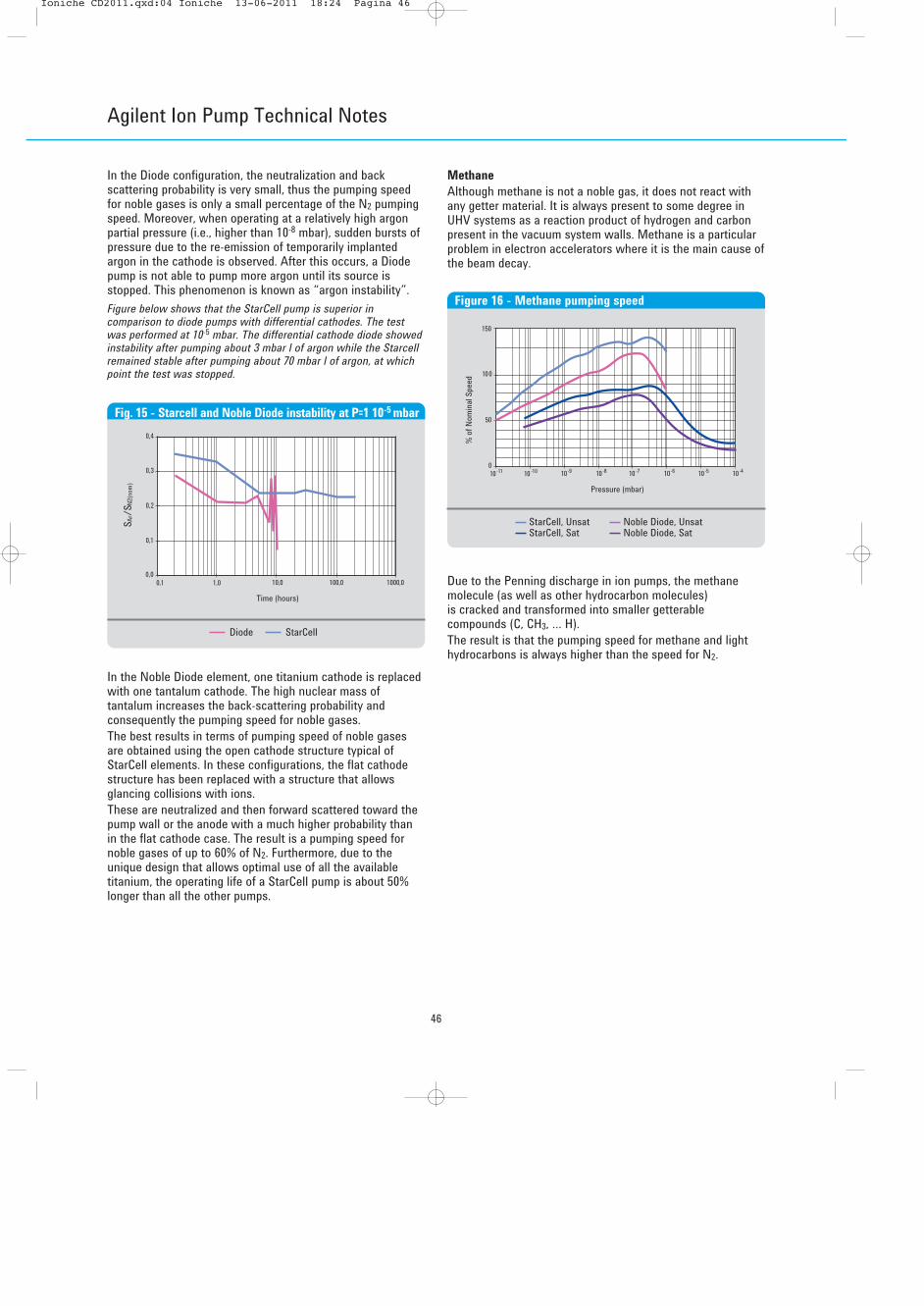
46
Agilent Ion Pump Technical Notes
In the Diode configuration, the neutralization and backscattering probability is very small, thus the pumping speedfor noble gases is only a small percentage of the N2 pumpingspeed. Moreover, when operating at a relatively high argonpartial pressure (i.e., higher than 10-8 mbar), sudden bursts ofpressure due to the re-emission of temporarily implantedargon in the cathode is observed. After this occurs, a Diodepump is not able to pump more argon until its source isstopped. This phenomenon is known as “argon instability”.Figure below shows that the StarCell pump is superior incomparison to diode pumps with differential cathodes. The testwas performed at 10-5 mbar. The differential cathode diode showedinstability after pumping about 3 mbar l of argon while the Starcellremained stable after pumping about 70 mbar l of argon, at whichpoint the test was stopped.
In the Noble Diode element, one titanium cathode is replacedwith one tantalum cathode. The high nuclear mass oftantalum increases the back-scattering probability andconsequently the pumping speed for noble gases.The best results in terms of pumping speed of noble gasesare obtained using the open cathode structure typical ofStarCell elements. In these configurations, the flat cathodestructure has been replaced with a structure that allowsglancing collisions with ions.These are neutralized and then forward scattered toward thepump wall or the anode with a much higher probability thanin the flat cathode case. The result is a pumping speed fornoble gases of up to 60% of N2. Furthermore, due to theunique design that allows optimal use of all the availabletitanium, the operating life of a StarCell pump is about 50%longer than all the other pumps.
Methane
Although methane is not a noble gas, it does not react withany getter material. It is always present to some degree inUHV systems as a reaction product of hydrogen and carbonpresent in the vacuum system walls. Methane is a particularproblem in electron accelerators where it is the main cause ofthe beam decay.
Due to the Penning discharge in ion pumps, the methanemolecule (as well as other hydrocarbon molecules) is cracked and transformed into smaller getterablecompounds (C, CH3, … H).The result is that the pumping speed for methane and lighthydrocarbons is always higher than the speed for N2.
S Ar/S
N2(n
om)
Time (hours)
0,0
0,2
0,1
0,1 1,0 10,0 100,0 1000,0
0,3
0,4
Fig. 15 - Starcell and Noble Diode instability at P=1 10-5 mbar
Diode StarCell
% o
f Nom
inal
Spee
d
Pressure (mbar)
0
150
10-11 10-10 10-9 10-8 10-7 10-6 10-5 10-4
100
50
Figure 16 - Methane pumping speed
StarCell, Unsat Noble Diode, UnsatStarCell, Sat Noble Diode, Sat
��������� ������� ����������� ��� ���������������

47
Basic Performance Factors
• Pumping speed, as in the case of any high vacuum pump, is one of the factors determining the ultimate (base)pressure of a system. However, ion pumps pump variousgases at different rates – from very fast for hydrogen toquite slow for argon. Thus, it is necessary to checkspecifications to match the pump properly to theapplication. The pump’s history in terms of gas load after abakeout also influences pumping speed. Agilent pumps arerated by their equilibrium or “saturated” speed levels.Unsatu r ated pumps temporarily deliver higher speeds,especially at UHV. A typical pumping speed vs pressurecurve is shown on page 44.
• Maximum throughput of an ion pump is located in the 10-4
to 10-5 mbar pressure range. Since ion pumps are generallyoperated at much lower pressures, throughput is generallynot a major consideration.
• Starting pressure is the pressure to which the ion pumpmust first be rough-pumped before the glow discharge willbe confined to the anode cell structure and the pumpingeffect begins. To prevent pump overheating and possibledamage when the pump is saturated at higher pressure, thecontrollers automatically reduce the output voltage tomaintain power below a safety level.
• Pump life is determined by various factors, includingcathode life; this is limited by cathode erosion, which isproportional to the aver age operating pressure. At 10-6
mbar, cathode life ranges from 35,000 to 80,000 hours.• Bakeability. In general, baking a UHV system and its ion
pump to 200 to 250 °C is adequate for outgassing, attaininglow pressures after atmospheric exposure. Some processesrequire higher bakeout temperatures. In general, ion pumpbodies can be baked at 450 °C when the magnets areremoved, or 350 °C when the magnets are on the pump.When bakeable cables are connected to the ion pumps,temperature should not exceed 220 °C.
Ion
Pum
ps
Ion Pumps
��������� ������� ����������� ��� ���������������

48
Agilent Titanium Sublimation Pump Technical Notes
Titanium Sublimation Pumps
Thin films of reactive materials have been used for “gascleanup” or “gettering” for over a century. The early electrontube makers were only able to mechanically pump to about1x10-4 mbar, but through the use of “getters” flashed on theinternal surfaces, pressures in the low 10-7 mbar scale wereattained. These getters were typically metals like barium,titanium, zirconium, or thorium. Gettering materials are stillused in tubes today even though pressures of 1 x 10⁻⁸ mbarare readily attained by the pumps in themanufacturing process.Gettering was not employed extensively in vacuum systemsuntil the 1960’s, when it was found to be highly compatiblewith ion pumping. Titanium was the metal commonly usedbecause of its availability and its ability to sublime readilyover a moderate temperature range.Applications
Due to cleanliness, bakeability, low power consumption,vibration-free operation, long pumping life, and high pumpingspeed, Titanium Sublimation Pumping (TSP) is the ideal cost-effective companion to ion pumping in ultrahigh vacuum.Applications for this pumping mode are found in many areas,such as:• Auger electron spectrometry• Electron spectroscopy for chemical analysis• Electron tube manufacturing• Mass spectrometers• Materials science conductor R&D• Nuclear physics• Outer space simulation• Particle accelerators• Secondary ion mass spectroscopy• Solid state semiconductorsBasic Performance Factors
• Pumping Speed. The pumping speed of a Ti film isproportional to the film area and to the sticking coefficient,that is the probability that an impinging gas molecule reactswith Ti forming a stable compound. The pumping speedsper unit area of a fresh evaporated Titanium film arereported in Table 1. Using these coefficients the intrinsicpumping speed (Si) of a Ti film can be evaluated using thefollowing equation:
Si[l/s] = Coefficient x Surface.
As the gas molecules react with the surface Ti atoms, thenumber of active sites decreases and, as a consequence, thepumping speed decreases. A plot of the specific pumpingspeed vs time at different pressures is reported in Figure 17.Using this plot it is possible to estimate how frequently the Tifilm has to be renewed.It must be noted that the actual pumping speed S of a TSPdepends on the conductance C between the active surfaceand the vacuum vessel according to the following equation:
1/S = 1/C + 1/Si
• Throughput. When the impingement rate of the gasmolecules on the active film becomes higher than the Tisublimation rate (excess of gas molecules respect theavailable Ti atoms), the pumping speed does not dependany more on the sticking coefficient. It is simply controlledby the quantity of the available Ti atoms according tostoichiometric reaction.
If n Ti atoms need to pump a gas molecule (example: 2Ti + N2 ’ 2TiN, n = 2), the gas throughput Q is given by:
Q [mbar l/s] = 0.13 R [gr ]____ __n h
Pluswhere R is the Ti sublimation rate. In this condition thepumping speed is not constant but it depends on the pressureand is directly proportional to the sublimation rate (Figure 18).
Time (minutes)
% o
f Max
imum
Pum
ping
Spee
dfo
r Nitr
ogen 50
0
70
30
100
10
20
40
60
8090
5E-7 mbar
1E-7 mbar1E-8 mbar
1E-9 mbar
1E-10 mbar
1E-11 mbar
1E-12 mbar
1 10 102 103 104 105 106
Figure 17 - Pumping speed vs time at different pressures
Table 1
Typical pumping speeds per square inch (per square centimeter) of titanium sublimation surface for various gases (liters per second)
Gas H2 N2 O2 CO CO2 H20 CH4 Ar He
Surface Temperature 20 °C 20 (3.1) 30 (4.7) 60 (9.3) 60 (9.3) 50 (7.8) 20 (3.1) 0 0 0–195 °C 65 (10.1) 65 (10.1) 70 (10.9) 70 (10.9) 60 (9.3) 90 (13.9) 0 0 0
��������� ������� ����������� ��� ���������������

49
Ion
Pum
ps
• Other factors. The overall performance of a titaniumsublimation pump is a function of several variables,including gas species, pressure, gas temperature, getterfilm temperature, getter film area, the geometry of the area,sublimation rate, sticking coefficient, and the conductancefrom the film to the area being evacuated. For furtherinformation, write for “Predicting and Evaluating TitaniumSublimation Pump Performance” by D.J. Harra, 1974(Vacuum Report VR-88).
Operation
Titanium Sublimation Pumping is accomplished by coating theinner surfaces of a vacuum system with sublimed titaniumfilms. Since it involves a chemical reaction, this kind ofpumping is useful where mainly active gases are present.The pumping speed of a unit area varies with various reactivegas species as shown in the following table. It can also beseen that cooling the substrate to liquid nitrogen temperaturemarkedly increases the speed for hydrogen and water.The gases thus “gettered” form stable compounds withtitanium and are stored in the system as such until they areremoved by cleaning. Since there is generally un-reactedpyrophoric titanium buried in the deposits, caution should beused in cleaning. If the desired gas throughput is known (Q = pumping speed x pressure) the maximum theoreticaloperating time is given by:
Operating time [h] = 0.13 T [gr]___ ____n Q [mbar l/s]
where T is the usable TitaniumFor example, using our cryopanel at 1 x 10⁻⁸ mbar with a threefilaments cartridge Ti source, the theoretical operating time isgiven by:
0.13 3.6 [gr] = 46,800 hrs = about 5 years___ _________________2 500 [l/s] x 10-8 [mbar]
After this time the filament cartridge should be replaced.Design Features
• All sources are mounted on 2 ¾” Agilent ConFlat Flangesand fit through 1 ½” ports.
• The three-filament source contains 3.3 grams of useful titanium.
• The Agilent Mini Ti-Ball source contains 15.2 grams of useful titanium.
Pressure (mbar)
Pum
ping
Spee
d (l/
sec)
110 -11
100000
10
100
1000
10000
70 cm dia
40 cm dia
10 cm dia
0,1 gr/h0,01 gr/h
10-10 10 -9 10-8 10-7 10-6 10-5 10-4 10-3 10-2
gas: nitrogen
temperature: 20 ° C
mode: continuoussublimation
Figure 18 - Pumping speed vs pressure
Ion Pumps
��������� ������� ����������� ��� ���������������

50
Agilent Ion Pump Service and Support Plan
Agilent Vacuum Technologies Products offers one of the mostcomprehensive service and support plans in the industry.As a worldwide, first class company we strive to offer addedvalue to our Customers wherever they may be located.Excellence in Service and Support is a key factor in added value.Support can be accomplished with qualified Engineers and anappropriate logistic infrastructure.Technical skills and infrastructure are two areas where weare continuously making medium and long-term investments.Our daily customer support philosophy is focused on twoimportant factors: quick response and no hassle.Agilent Vacuum Products is committed to providing ourCustomers with the most comprehensive service planspossible.The following pages detail the standard sections of our IonPump Service and Support Plan. For more information, or ifyou have a need for customized solutions, please contactyour Agilent representative.Often, excellent products are not enough: Agilent’s constantpresence with Customer Service as a responsive partner iswhat really makes a difference.
Worldwide Parts Sourcing Plan
• Exchange and Repair Programs
Agilent’s Ion Pumps and Controllers offer unmatchedreliability, performance and cleanliness.To maximize uptime, and for those occasions where time isessential, Agilent offers exchange units for advanceshipment.Exchange units are fully remanufactured to the same strictstandards as new products.If requested, your Exchange unit can be shipped forovernight delivery. This efficiency is due to our logisticinfrastructure and is the result of excellent teamworkamong our Service and Customer Service Teams!
The Repair Program is available for those situations wherethe control of assets is important and when the requestedturn around time is less critical.The Exchange and Repair Programs allow global OEMs andEnd-Users consistent delivery time, pricing, part numbers,and order processing procedures.
• End User Extended Warranty
The End User Extended Warranty is a Service Agreementthat provides coverage extension beyond the standard 12months warranty of a product. It extends for additional 12months the coverage from failures due to defects inmaterial and workmanship.By extending the warranty of purchased products, post-sales satisfaction is guaranteed. This is the result of therelevant cost decrease while cost predictability isincreased.The End User Extended Warranty has been designed tocover the needs of the High Energy Physics Ultra HighVacuum applications.
• Ordering Information for End User Extended Warranty
High Energy Physics UHV Applications
Pumps Part Number
Extd. Warr. HEP 12M Ion Pump 20 l/s class EW919VIP20Extd. Warr. HEP 12M Ion Pump 40 l/s class EW919VIP40Extd. Warr. HEP 12M Ion Pump 55 l/s class EW919VIP55Extd. Warr. HEP 12M Ion Pump 75 l/s class EW919VIP75Extd. Warr. HEP 12M Ion Pump 150 l/s class EW919VIP150Extd. Warr. HEP 12M Ion Pump 300 l/s class EW919VIP300Extd. Warr. HEP 12M Ion Pump 500 l/s class EW919VIP500Extd. Warr. HEP 12M Ion Pump (other config.) EW919VIP
Controllers Part Number
Extd. Warr. 12M Minivac Controller EW929MINIVACExtd. Warr. HEP 12M 4UHV CTRL 1-2 Pumps EW919UHV2PExtd. Warr. HEP 12M 4UHV CTRL 3-4 Pumps EW919UHV4PExtd. Warr. 12M TSP Controller EW929TSP
��������� ������� ����������� ��� ��������������

51
Technical Assistance
As a Agilent Customer, you can rely on an attentive andprofessional support staff, dedicated to providing you with theeasiest and most personalized service possible.• Customer Support
Our toll-free lines, with mother tongue Technical SupportEngineers at worldwide locations, allow us to provide youwith quick, corrective responses to your needs.Whenever a new problem is identified and solved by oursupport personnel, it is entered into our technical supportsystem and becomes available to all Agilent technicalsupport centers. This system allows all Agilent locations toprovide excellent first and second level technical support tocustomers worldwide. In addition, the technical supportcenters are in daily contact with our R&D departments forthird level support.Call us today for more information.
Americas
North America: Tel. 1.800.882.7426 (toll-free)Fax (1) 781.860.5437
Central and South America: Tel. (1) 781.861.7200Fax (1) 781.860.5437
Asia
Japan: Tel. 0120-655-040 (toll-free)Fax (81) 3.5232.1710 (dedicated line)
Korea: Tel. 080.222.2452 (toll-free)Fax (82) 2.3452.2451 (dedicated line)
Taiwan Tel. 0800-051342 (toll-free)Fax (886) 2.2698.9678 (dedicated line)
China Tel. 800.820.8266 (toll-free)Fax (86) 10.6439.1318 (dedicated line)
Europe and Israel
Austria, Belgium, Finland, France, Germany, Holland, Ireland,Israel (*), Italy, Portugal, Spain, Switzerland, UK:
Tel. 00.800.234.234.00 (toll-free)Fax 00.800.345.345.00 (fax free)
(*) From Israel dial 012 instead of initial 00Other Countries
Tel. (39) 011.9979.369 (dedicated line)Fax (39) 011.9979.330 (dedicated line)
• Application Support - Application Training
Agilent has a leadership position in vacuum technologywith continuous search for innovative solutions throughresearch and development.To meet the most demanding needs, our ApplicationEngineer Team can bring our knowledge into your factory.Application Support is a project-based activity where ourexperts assist you towards the solution of your applicationissues that might arise both at pre and post-sale level.By designing solutions that meet Customers’ needs, Agilent aims to create a positive and synergetic relationship with customers.Our experts can keep you well-informed and up-to-date onindustrial and scientific applications with the goal ofoptimizing the use of our products on your system as wellas the development of new vacuum techniques.
Ion
Pum
ps
Ion Pumps
��������� ������� ����������� ��� ���������������
![AGILENT SPUTTER ION PUMPS A 60 YEAR HISTORY · In the same years triode pumps were invented by W.M. Brubaker (Consolidated Electrodynamics Corporation) [7,8] and Varian began to sell](https://img.dokumen.tips/doc/110x75/5e31f70f482ba47b871b3358/agilent-sputter-ion-pumps-a-60-year-history-in-the-same-years-triode-pumps-were.jpg)