Embed Size (px)
Citation preview

Agenda for the meeting
for the Preparatory Survey on the Project for Rehabilitation of Trunk Road, Phase IV
in the Federal Democratic Republic of Ethiopia
Venue: ERA Central Regional Directorate Office, Alemgena Time: 2010/10/19, 14:30 16:00 Agenda: The meeting will discuss matters related to the abovementioned project with
particular attention to the following items; 1. Applicable Design Standard 2. Typical Cross Sections of Road 3. Countermeasure for the Expansive soil (Black Cotton soil) 4. Bridge Planning (Bridges and culverts) including cross sections Meeting Material Content
(1) Table of Geometric Design Conditions (2) Figure of Typical Cross Section of Road (3) Figure of Countermeasure for the BC soil (4) Table of Subgrade Condition in the Project Road (5) Table of Concept of Structures (Bridges and Culverts)
A-6-12
The Preparatory Survey on the Project for Rehabilitation of Trunk Road, Phase IV in the Federal Democratic Republic of Ethiopia
1
Discussion for the Design Conditions and Concepts 1. Applicable Design Standard
(1) Design Standards
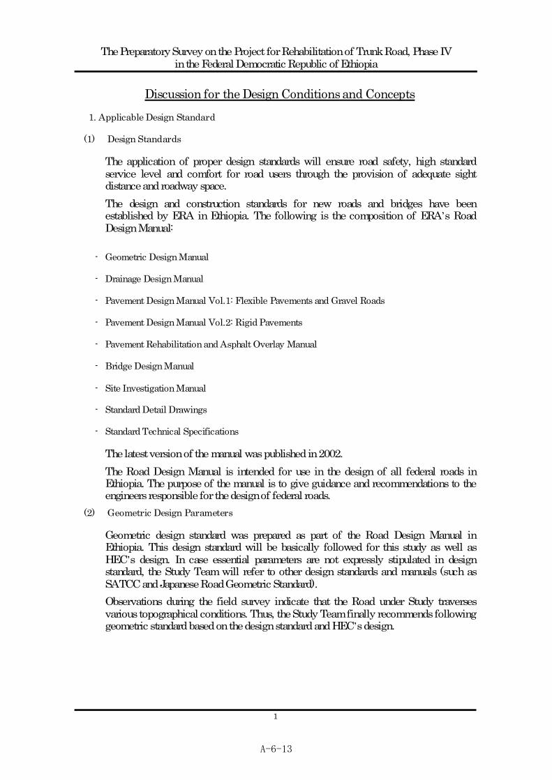
The application of proper design standards will ensure road safety, high standard service level and comfort for road users through the provision of adequate sight distance and roadway space. The design and construction standards for new roads and bridges have been established by ERA in Ethiopia. The following is the composition of ERA s Road Design Manual:
- Geometric Design Manual
- Drainage Design Manual
- Pavement Design Manual Vol.1: Flexible Pavements and Gravel Roads
- Pavement Design Manual Vol.2: Rigid Pavements
- Pavement Rehabilitation and Asphalt Overlay Manual
- Bridge Design Manual
- Site Investigation Manual
- Standard Detail Drawings
- Standard Technical Specifications
The latest version of the manual was published in 2002. The Road Design Manual is intended for use in the design of all federal roads in Ethiopia. The purpose of the manual is to give guidance and recommendations to the engineers responsible for the design of federal roads.
(2) Geometric Design Parameters
Geometric design standard was prepared as part of the Road Design Manual in Ethiopia. This design standard will be basically followed for this study as well as HEC s design. In case essential parameters are not expressly stipulated in design standard, the Study Team will refer to other design standards and manuals (such as SATCC and Japanese Road Geometric Standard). Observations during the field survey indicate that the Road under Study traverses various topographical conditions. Thus, the Study Team finally recommends following geometric standard based on the design standard and HEC s design.
A-6-13
The Preparatory Survey on the Project for Rehabilitation of Trunk Road, Phase IV in the Federal Democratic Republic of Ethiopia
2
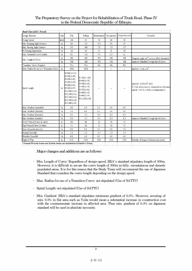
Major changes and additions are as follows:
- Min. Length of Curve: Regardless of design speed, ERA s standard stipulates length of 300m. However, it is difficult to secure the curve length of 300m in hilly, mountainous and densely populated areas. It is for this reason that the Study Team will recommend the use of Japanese Standard that considers the curve length depending on the design speed.
- Max. Radius for use of a Transition Curve: not stipulated (Use of SATTC)
- Spiral Length: not stipulated (Use of SATTC)
- Min. Gradient: ERA s standard stipulates minimum gradient of 0.5%. However, securing of min. 0.5% in flat area such as Yeda would mean a substantial increase in construction cost with the commensurate increase in affected area. Thus min. gradient of 0.3% on Japanese standard will be used in absolute necessity.
A-6-14
The Preparatory Survey on the Project for Rehabilitation of Trunk Road, Phase IV in the Federal Democratic Republic of Ethiopia
3
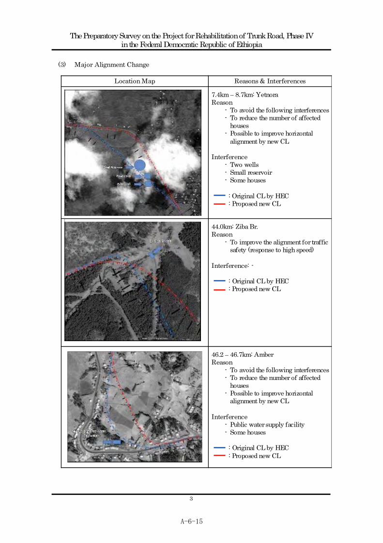
(3) Major Alignment Change
Location Map Reasons & Interferences
7.4km 8.7km: Yetnora Reason
- To avoid the following interferences- To reduce the number of affected
houses - Possible to improve horizontal
alignment by new CL Interference
- Two wells - Small reservoir - Some houses
: Original CL by HEC : Proposed new CL
44.0km: Ziba Br. Reason
- To improve the alignment for traffic safety (response to high speed)
Interference: -
: Original CL by HEC : Proposed new CL
46.2 46.7km: Amber Reason
- To avoid the following interferences- To reduce the number of affected
houses - Possible to improve horizontal
alignment by new CL Interference
- Public water supply facility - Some houses
: Original CL by HEC
: Proposed new CL
A-6-15
The Preparatory Survey on the Project for Rehabilitation of Trunk Road, Phase IV in the Federal Democratic Republic of Ethiopia
4
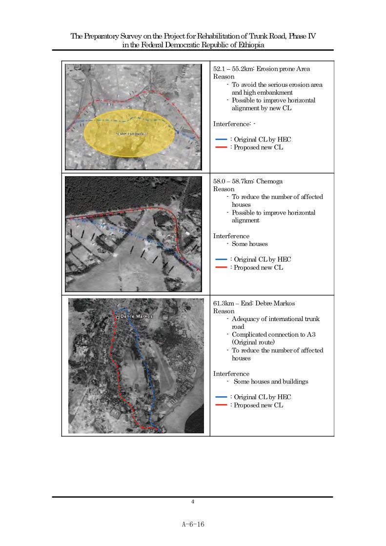
52.1 55.2km: Erosion prone Area Reason
- To avoid the serious erosion area and high embankment
- Possible to improve horizontal alignment by new CL
Interference: -
: Original CL by HEC : Proposed new CL
58.0 58.7km: Chemoga Reason
- To reduce the number of affected houses
- Possible to improve horizontal alignment
Interference
- Some houses
: Original CL by HEC : Proposed new CL
61.3km End: Debre Markos Reason
- Adequacy of international trunk road
- Complicated connection to A3 (Original route)
- To reduce the number of affected houses
Interference
- Some houses and buildings
: Original CL by HEC : Proposed new CL
A-6-16

The Preparatory Survey on the Project for Rehabilitation of Trunk Road, Phase IV in the Federal Democratic Republic of Ethiopia
5
(4) Pavement Design
Pavement Design Condition: It is based on the HEC s design
Design Life: 15years
Sub-grade Strength Class: S2 (0km 53km), S3 (53km 65km)
Vehicle Equivalent Factor (VEF): see table below:
Vehicle Category Base year Traffic Tc EF CESA
Large Bus 72 675853.48 2.29 1547704.47 Medium Truck 45 403331.17 2.76 1113194.03 Heavy Truck 36 322664.93 7.25 2339320.78 Truck and Trailer 46 412294.08 12.26 5054725.42 Total 10,054,944.70Applying lane distribution factor of 90% for single lane i.e. .9*10054944.7
9,049,450.23(Class T6)
Based on ERA s manuals, for traffic classes of T6, the required pavement layers with asphalt concrete surfacing, crushed granular road base and granular sub-base for the design periods of 15 years are as shown in the table below.
Pavement Layers (mm) for 15 years & traffic class T6 Station Sub-grade
class AC Base course Sub- base G.C 0km-53km S2 100 200 225 200 53km-65km S3 100 200 250 -
Detail design report by HEC had finally recommended the following pavement layers because uncertainties such as the traffic volume and analysis as well as the sub grade soil testing and evaluation should be considered.
Pavement Layers (mm) for 15 years & traffic class T6 Station Sub-grade
class Traffic class AC Base course Sub- base G.C
0km-53km S2 T6 100 200 225 200 53km-65km S3 T6 100 250 300 -
However, for Japanese ODA policy, minimum requirement based on technical theory is acceptable. Thus the Study Team will recommend the following pavement layers:
Pavement Layers (mm) for 15 years & traffic class T6
Station Sub-gradeclass
Traffic class
AC Base course Sub- base G.C 0km-53km S2 T6 100 200 250* 200 53km-65km S3 T6 100 200 250 -
*225mm of sub-base required by the manual will be changed to 250mm in consideration of easy construction and supervision.
A-6-17
The Preparatory Survey on the Project for Rehabilitation of Trunk Road, Phase IV in the Federal Democratic Republic of Ethiopia
6
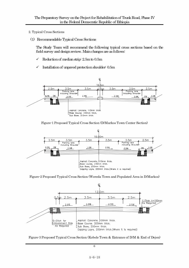
2. Typical Cross Sections
(1) Recommendable Typical Cross Sections
The Study Team will recommend the following typical cross sections based on the field survey and design review. Main changes are as follows:
Reduction of median strip: 2.5m to 0.5m
Installation of unpaved protection shoulder: 0.5m
Figure-1 Proposed Typical Cross Section (D/Markos Town Center Section)
Figure-2 Proposed Typical Cross Section (Wereda Town and Populated Area in D/Markos)
Figure-3 Proposed Typical Cross Section (Kebele Town & Entrance of D/M & End of Dejen)
A-6-18
The Preparatory Survey on the Project for Rehabilitation of Trunk Road, Phase IV in the Federal Democratic Republic of Ethiopia
7
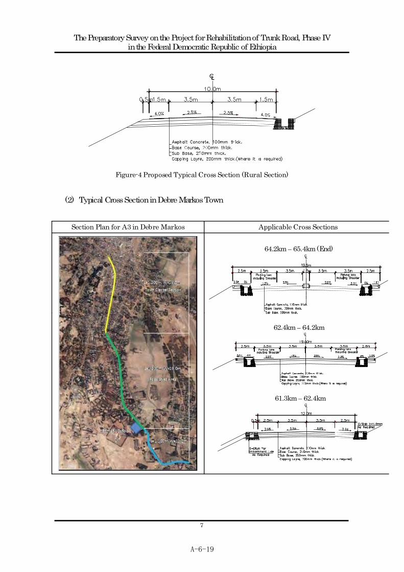
Figure-4 Proposed Typical Cross Section (Rural Section)
(2) Typical Cross Section in Debre Markos Town
Section Plan for A3 in Debre Markos Applicable Cross Sections
64.2km 65.4km (End)
62.4km 64.2km
61.3km 62.4km
A-6-19

The Preparatory Survey on the Project for Rehabilitation of Trunk Road, Phase IV in the Federal Democratic Republic of Ethiopia
8
3. Countermeasures for the BC Soil (Expansive Soil):e.g. Rural Area
Black cotton soils are problematic for Civil Engineers, because of their unconventional behavior. These soils show large volumetric changes with respect to seasonal variation of moisture content. These soils when subjected to vehicular traffic, road pavement heaves and cracks due to cycles of swelling and shrinkage. The Study Team will recommend the following measures based on the field survey, soil testing and visits made to similar projects.
Figure-1 Existing Pavement Section in Rural Area
Figure-2 New Road Section (Bypass) in Rural Area
A-6-20

The Preparatory Survey on the Project for Rehabilitation of Trunk Road, Phase IV in the Federal Democratic Republic of Ethiopia
9
Subgrade condition between Dejen and Lumame Boringor Pit Chainage Location BCS Red.
/ BrnN
value CBR Swell% PI NMC S.L. Eex
NTP 01 1+500 0.8-2.0 < 10 38 NTP 02 4+000 0.6-2.6 < 10 2 10.0 51 112NBH 01 5+060 1.0-2.5 8-9 77 39 3.2 NTP 03 5+500 0.5-1.9 < 10 48 BH 09 8+500 Yetnora 0.95-2.7 2-6 47 NTP 05 9+500 0.8-2.8 < 10 46 BH 10 10+500 0.0-2.0 3-10 36 31 BH 11 11+400 0.0-4.0 4-9 25 40 NTP 06 11+500 0.5-3.1 < 10 73 BH 12 12+500 Bechet 0.5-2.5 1-6 52 46 NTP 07 13+500 0.7-2.5 < 10 2 8.0 42 97 NBH 02 14+560 0.6-2.0 8 72 39 2.8 NTP 08 15+500 0.8-2.5 < 10 62 NTP 09 16+500 0.9-2.6 < 10 73 NTP 10 17+500 0.6-2.4 < 10 74 BH 13 18+500 Taba 0.0-3.0 1-4 78 51 NTP 11 19+500 Wejel 0.5-2.4 < 10 47 BH 14 20+000 Aba Adem 0.0-2.1 3-4 52 NBH 03 20+090 Aba Adem 0.5-3.5 9-14 70 44 4,4 NTP 12 21+500 1.1-2.4 < 10 51 NBH 04 22+040 Abeya 1.0-13.0 2-9 51 46 7.3 NBH 05 22+080 Abeya 1.0-11.0 4-11 53 44 NTP 13 23+000 0.6-3.0 < 10 2 8.4 51 128NTP 14 24+000 1.6-2.5 < 10 57 NTP 15 26+500 0.8-3.0 < 10 2 12.4 43 53 9 90 NBH 06 26+500 0.6-2.5 4-5 52 53 6.2 NTP 16 27+500 0.7-2.7 < 10 71 NTP 17 29+000 0.5-3.0 < 10 63 NBH 07 29+300 Bogena 0.6-3.9 10 43 31 NBH 08 29+390 Bogena 1.0-3.9 5-6 70 61 NPT 18 30+000 1.1-3.0 < 10 59 Note; BCS: Black cotton soil, Eex: Expansiveness
A-6-21
The Preparatory Survey on the Project for Rehabilitation of Trunk Road, Phase IV in the Federal Democratic Republic of Ethiopia
10
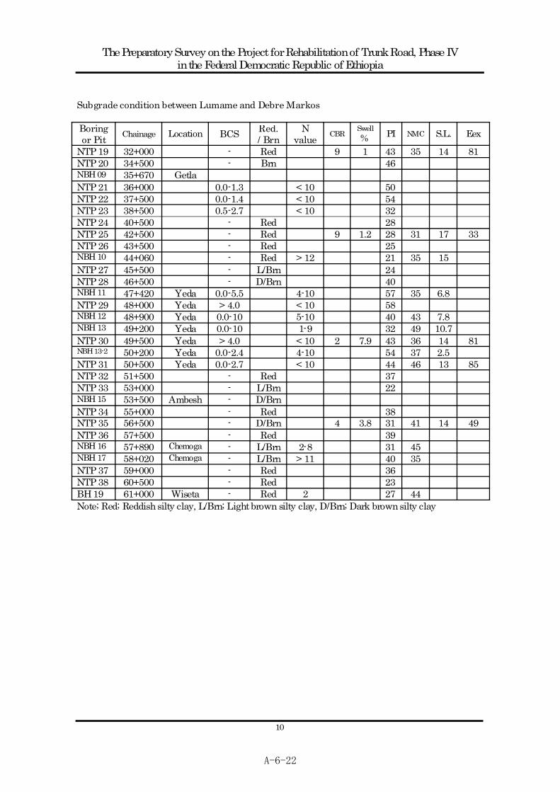
Subgrade condition between Lumame and Debre Markos Boringor Pit Chainage Location BCS Red.
/ BrnN
value CBRSwell% PI NMC S.L. Eex
NTP 19 32+000 - Red 9 1 43 35 14 81 NTP 20 34+500 - Brn 46 NBH 09 35+670 Getla NTP 21 36+000 0.0-1.3 < 10 50 NTP 22 37+500 0.0-1.4 < 10 54 NTP 23 38+500 0.5-2.7 < 10 32 NTP 24 40+500 - Red 28 NTP 25 42+500 - Red 9 1.2 28 31 17 33 NTP 26 43+500 - Red 25 NBH 10 44+060 - Red > 12 21 35 15 NTP 27 45+500 - L/Brn 24 NTP 28 46+500 - D/Brn 40 NBH 11 47+420 Yeda 0.0-5.5 4-10 57 35 6.8 NTP 29 48+000 Yeda > 4.0 < 10 58 NBH 12 48+900 Yeda 0.0-10 5-10 40 43 7.8 NBH 13 49+200 Yeda 0.0-10 1-9 32 49 10.7 NTP 30 49+500 Yeda > 4.0 < 10 2 7.9 43 36 14 81 NBH 13-2 50+200 Yeda 0.0-2.4 4-10 54 37 2.5 NTP 31 50+500 Yeda 0.0-2.7 < 10 44 46 13 85 NTP 32 51+500 - Red 37 NTP 33 53+000 - L/Brn 22 NBH 15 53+500 Ambesh - D/Brn NTP 34 55+000 - Red 38 NTP 35 56+500 - D/Brn 4 3.8 31 41 14 49 NTP 36 57+500 - Red 39 NBH 16 57+890 Chemoga - L/Brn 2-8 31 45 NBH 17 58+020 Chemoga - L/Brn > 11 40 35 NTP 37 59+000 - Red 36 NTP 38 60+500 - Red 23 BH 19 61+000 Wiseta - Red 2 27 44 Note; Red; Reddish silty clay, L/Brn; Light brown silty clay, D/Brn; Dark brown silty clay
A-6-22

The Preparatory Survey on the Project for Rehabilitation of Trunk Road, Phase IV in the Federal Democratic Republic of Ethiopia
11
4. BRIDGE PLANNING
(1) Use of Existing Bridges
Existing bridges will be used if they meet the criteria for compatibility to the new road alignment, structural soundness, and functional requirements. The Bridge Design manual of ERA requires the minimum carriageway of 7.0 m for 2-lane bridges. If necessary and if feasible, repair works will be conducted to improve the function and to satisfy the requirements.
(2) Bridge Length
Based on the necessary clearance under the superstructure such as waterway function and topography, the bridge length will be decided.
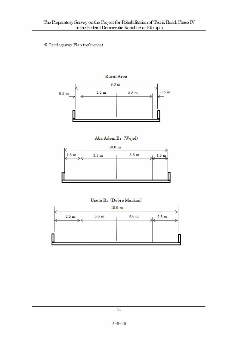
(3) Carriageway
Carriageway will be decided according to the Bridge Design Manual of ERA, in consideration of the continuity with approach roads and expected number of pedestrians. The carriageway width of bridges in rural area is 8.0 , (0.5 +3.5 +3.5
+0.5 ). The Aba Adem Bridge which is located in Wejel and the Useta Bridge in Debre Markos are expected to be used by many pedestrians. The carriageway of the Aba Adem Bridge and the Useta Bridge is 10 , (1.5 +3.5 +3.5 +1.5 ), and 12m, (2.5 +3.5 +3.5 +2.5 ), respectively taking into account the traffic conditions.
(4) Bridge Type
Type by Material
The Reinforced Concrete Bridge (RC Bridge) is the most suitable bridge type for short spans. Table-1 shows the comparison of bridge types by materials.
Type Features Evaluation
Reinforced Concrete Bridge
Suitable for short spans No major technical difficulties No difficulty in obtaining necessary materials No difficulty in Quality Control Cost-effective Suitable for Technology Transfer
Concrete Bridge
Prestressed Concrete Bridge
Suitable for longer spans than RC bridges Light weight than RC bridges Advance technology Need of imported materials Difficulty in Quality Control Costly than RC bridges
Steel Bridge
Imported materials Difficulty in construction Costly than concrete bridges Difficulty at maintenance stage Easy to repair than concrete bridges
A-6-23

The Preparatory Survey on the Project for Rehabilitation of Trunk Road, Phase IV in the Federal Democratic Republic of Ethiopia
12
Structural Type
Structural Type will be decided by the following criteria.
Structural Type Span Range
Reinforced Concrete Slab Bridge 5 10
Reinforced Concrete Girder Bridge 10 20
RC Box Culvert
When the bridge construction is judged to be difficult or not appropriate due to difficult site conditions, the RC Box Culvert will be planned. The following table compares the bridges and RC box culverts.
Structure Features
Bridges
Suitable for longer spans Wider clearance under the superstructure Concentration of forces at abutments and piers Need of strong ground layer Need of bearing supports and expansion joints
RC Box Culverts
Smaller clearance than that of bridges No bearing supports and expansion joints No need of abutments and piers Applicable to less strong ground condition No difficulty in adjustment of road surface
(5) Design Method
The bridge design shall meet the Bridge Design Manual of ERA. However, calculation is based on Japanese bridge design methods and check if the result meets the Bridge Design Manual of ERA.
Bridge Planning a) Existing Bridges
Bridge Length Carriageway Type Major Repair Asamatech 5.0 m 7.0 m RC Girder Slab, Parapet Taba 13+13 m 7.3 m RC Girder None Bogena 13.1 m 7.0 m RC Girder Slab, Parapet Chemoga 67.0 m 7.0 m Masonry Arch Slab, Parapet
b) New Bridges
Bridge Length Carriageway Type Substructure TypeBechet 17+17 m 8.0 m RC Girder Direct Foundation Abadem 15 m 10.0 m RC Girder Direct Foundation Abeya 3@ 4.5 m 8.0 m RC Culvert A3-4-012 2@ 4.5 m 8.0 m RC Culvert Getla 15+15 m 8.0 m RC Girder Direct Foundation
A-6-24

The Preparatory Survey on the Project for Rehabilitation of Trunk Road, Phase IV in the Federal Democratic Republic of Ethiopia
13
A3-4-017 15 m 8.0 m RC Girder Direct Foundation Zeba 15 m 8.0 m RC Girder Direct Foundation Yeda-A 2@ 4.5 m 8.0 m RC Culvert Yeda-B 2@ 4.5 m 8.0 m RC Culvert Yeda-C 5@ 4.5 m 8.0 m RC Culvert Ambesh 2@ 4.5 m 8.0 m RC Culvert Useta 10+10 m 12.0 m RC Girder Direct Foundation
c) Existing and New Bridges (reference)
Existing Bridge New Bridge Bridge
Length Carriageway Type Length Carriageway Type Asamatech
5.0 m 7.0 m RC Girder
Bechet
32.0 m 6.0 m Masonry Arch
17+17 m 8.0 m RC Girder
Taba
13+13 m
7.3 m RC Girder
Abadem
12.0 m 6.0 m Masonry Arch
15m 10.0 m RC Girder
Abeya
7+7+7 m
6.0 m RC Girder
3@ 4.5 m 8.0 m RC Culvert
Bogena
13.1 m 7.0 m RC Girder
A3-4-012
7.8 m 5.5 m Masonry Arch
2@ 4.5 m 8.0 m RC Culvert
Getla
13.1 m 7.0 m RC Girder
15+15 m 8.0 m RC Girder
A3-4-017
7.0 m 6.0 m Masonry Arch
15 m 8.0 m RC Girder
Zeba
11.0 m 5.5 m RC Girder
15 m 8.0 m RC Girder
Yeda-1
4@ 5.0m
7.0 m RC Girder
2@ 4.5 m 8.0 m RC Culvert
Yeda-2
4@ 5.0m
7.0 m RC Girder
2@ 4.5 m 8.0 m RC Culvert
Yeda-3
6+6+6 m
7.0 m RC Girder
Yeda-4
3.5+4 m
7.0 m RC Girder
5@ 4.5 m 8.0 m RC Culvert
Ambesh
8.0 m 6.0 m Masonry Arch
2@ 4.5 m 8.0 m RC Culvert
Chemoga
67.0 m 7.0 m Masonry Arch
Useta
12.3 m 5.0 m RC Girder
10+10 m 12.0 m RC Girder
A-6-25
The Preparatory Survey on the Project for Rehabilitation of Trunk Road, Phase IV in the Federal Democratic Republic of Ethiopia
14
d) Carriageway Plan (reference)
A-6-26

A-6-27

A-6-28

The Preparatory Survey on the Project for Rehabilitation of Trunk Road, Phase IV in the Federal Democratic Republic of Ethiopia
1
1. Acceptable Minimum Gradient (Acceptable Geometric Parameter)
As discussed in the previous meetings held on 19th and 22nd of October, 2010, the JICA Study Team recommended using 0.3% as min. gradient as follows:
- Min. Gradient: ERA s standard stipulates minimum gradient of 0.5%. However, securing of min. 0.5% in flat area such as Yeda would mean a substantial increase in construction cost with the commensurate increment of affected area. Thus min. gradient of 0.3% according to Japanese standard will be used in absolute necessity.
For this recommendation, the Study Team fills in the gaps as follows.
2. Other Standards Recommendation
A. SATCC: not stipulated B. AASHTO: Flat grades can typically be used without any problem on uncurbed highways where the cross slope is adequate to drain the surface water laterally. With curbed highways or streets, longitudinal grade should be provided to facilitate surface drainage. An appropriate minimum grade is typically 0.5 percent, but grades of 0.30 percent may be used where there is a high-type pavement accurately sloped and supported on firm sub-grade. C. Japanese Standard: Flat grades are normally preferable, but long section with flat
A-6-29
The Preparatory Survey on the Project for Rehabilitation of Trunk Road, Phase IV in the Federal Democratic Republic of Ethiopia
2
grade will create some problem. Surface water on road should be drained by cross fall, but surface water sometimes remains on road surface due to problems such as rainfall intensity, drainage size, etc. It is therefore usual to set vertical gradient at least between 0.3 and 0.5 percent.
3. Reasons of Recommendation of 0.3 %
1) Livestock Corridor
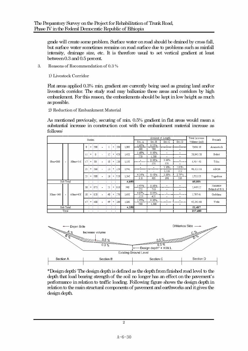
Flat areas applied 0.3% min. gradient are currently being used as grazing land and/or livestock corridor. The study road may balkanize these areas and corridors by high embankment. For this reason, the embankments should be kept in low height as much as possible. 2) Reduction of Embankment Material
As mentioned previously, securing of min. 0.5% gradient in flat areas would mean a substantial increase in construction cost with the embankment material increase as follows:
*Design depth: The design depth is defined as the depth from finished road level to the depth that load bearing strength of the soil no longer has an effect on the pavement s performance in relation to traffic loading. Following figure shows the design depth in relation to the main structural components of pavement and earthworks and it gives the design depth.
A-6-30

The Preparatory Survey on the Project for Rehabilitation of Trunk Road, Phase IV in the Federal Democratic Republic of Ethiopia
3
Table: Standard for the Design Depth (i.e. Tanzania, S.A., Japan)
Tanzania Standard S.A. Standard Design Depth (m) Road Type General Heavy Load Road Class Design
depth
Japanese Standard
A 1.0 1.2 Paved Trunk 0.8 1.2 B 0.8 1.0 C 0.8 Others 0.6 1.0 D 0.7
1.0m from bottom of sub-base
4. Conclusion
From the results of study mentioned above, the Study Team recommend using gradient of 0.3% as minimum gradient under the following conditions based on AASHTO.
- To use asphalt concrete pavement: 10cm - To set accurate slope (Cross slope) - To support on firm sub-grade (well-compacted improved sub-grade)
A-6-31

The Preparatory Survey on the Project for Rehabilitation of Trunk Road, Phase IV in the Federal Democratic Republic of Ethiopia
1
Countermeasure for expansive soil on the Trunk Road A3 between Dejen and Debre Markos
1. Principle (ERA Site Investigation Manual 2002)
Mitigation measures for expansive soils are mentioned as follows in the Manual
(a) Realignment; this solution is possible only if the areas covered with expansive clays are of limited extent.
(b) Excavation and replacement; this simple procedure effectively eliminates the problems and is therefore recommended as much as possible. The investigations should focus on minimizing haulage of the materials, and this method will be economically viable only if suitable backfill material is available in the vicinity of the project road.
(c) Treatment with lime; treatment of expansive soils with hydrated lime can give good results. The addition of 4 to 6% of lime is usually required. This treatment is, however, costly, in particular because it is necessary to treat a substantial thickness of soil (minimum 30cm compacted thickness). Lime treatment would therefore be considered advantageous only where investigations failed to locate suitable backfill material.
(d) Minimizing Moisture Changes and Consequent Movements; if the above methods cannot be utilized, because of excessive costs or the absence of suitable backfill or replacement material, expansive clays may be used for fill and sub-grade. Special Practices are then necessary to avoid ingress of moisture into the road pavement that results in detrimental volume changes in the swelling soils. (Confining expansive clays under protective blankets, etc)
As the manual states, in case suitable backfill material is available, replacement procedure is applied as countermeasure for expansive soils. Since suitable backfill material is available in the vicinity of the project road, replacement method is preferable.
A-6-32
The Preparatory Survey on the Project for Rehabilitation of Trunk Road, Phase IV in the Federal Democratic Republic of Ethiopia
2
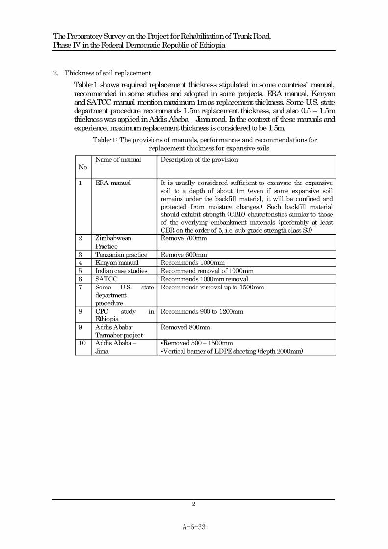
2. Thickness of soil replacement
Table-1 shows required replacement thickness stipulated in some countries manual, recommended in some studies and adopted in some projects. ERA manual, Kenyan and SATCC manual mention maximum 1m as replacement thickness. Some U.S. state department procedure recommends 1.5m replacement thickness, and also 0.5 1.5m thickness was applied in Addis Ababa Jima road. In the context of these manuals and experience, maximum replacement thickness is considered to be 1.5m.
Table-1: The provisions of manuals, performances and recommendations for replacement thickness for expansive soils
NoName of manual Description of the provision
1 ERA manual It is usually considered sufficient to excavate the expansive soil to a depth of about 1m (even if some expansive soil remains under the backfill material, it will be confined and protected from moisture changes.) Such backfill material should exhibit strength (CBR) characteristics similar to those of the overlying embankment materials (preferably at least CBR on the order of 5, i.e. sub-grade strength class S3)
2 Zimbabwean Practice
Remove 700mm
3 Tanzanian practice Remove 600mm 4 Kenyan manual Recommends 1000mm 5 Indian case studies Recommend removal of 1000mm 6 SATCC Recommends 1000mm removal 7 Some U.S. state
department procedure
Recommends removal up to 1500mm
8 CPC study in Ethiopia
Recommends 900 to 1200mm
9 Addis Ababa- Tarmaber project
Removed 800mm
10 Addis Ababa Jima
Removed 500 1500mm Vertical barrier of LDPE sheeting (depth 2000mm)
A-6-33
The Preparatory Survey on the Project for Rehabilitation of Trunk Road, Phase IV in the Federal Democratic Republic of Ethiopia
3
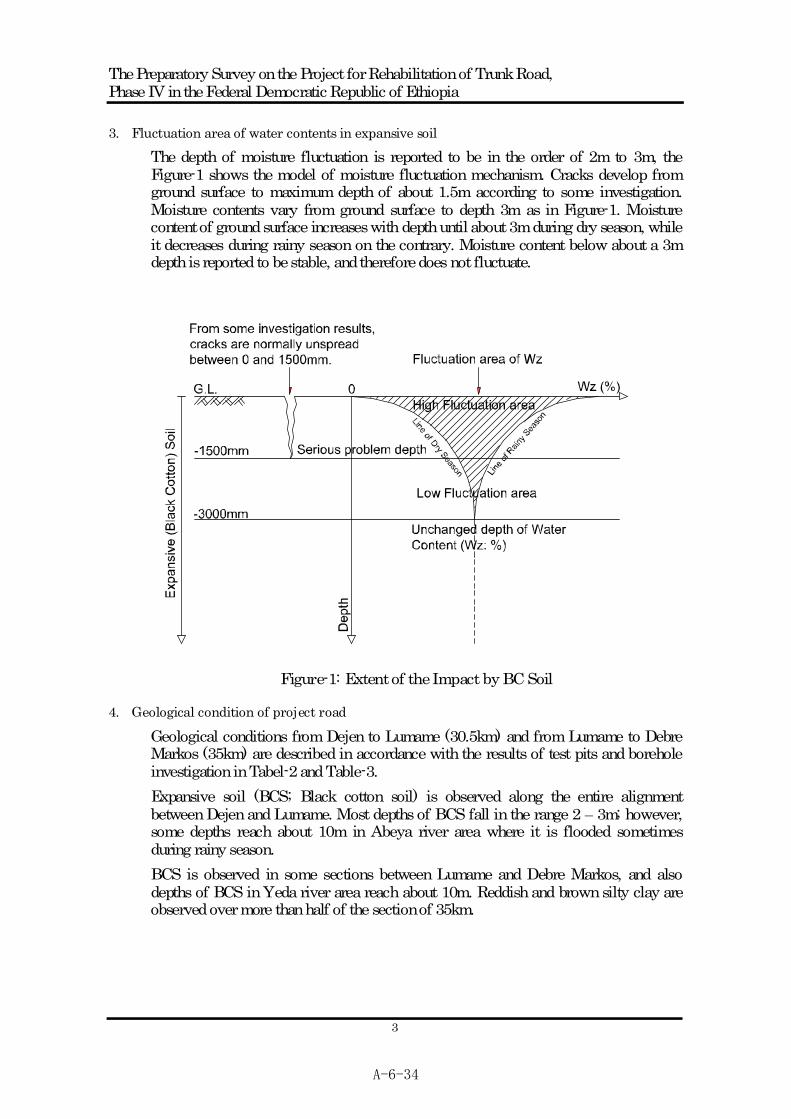
3. Fluctuation area of water contents in expansive soil
The depth of moisture fluctuation is reported to be in the order of 2m to 3m, the Figure-1 shows the model of moisture fluctuation mechanism. Cracks develop from ground surface to maximum depth of about 1.5m according to some investigation. Moisture contents vary from ground surface to depth 3m as in Figure-1. Moisture content of ground surface increases with depth until about 3m during dry season, while it decreases during rainy season on the contrary. Moisture content below about a 3m depth is reported to be stable, and therefore does not fluctuate.
Figure-1: Extent of the Impact by BC Soil
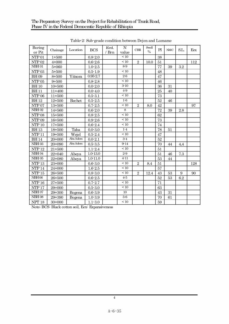
4. Geological condition of project road
Geological conditions from Dejen to Lumame (30.5km) and from Lumame to Debre Markos (35km) are described in accordance with the results of test pits and borehole investigation in Tabel-2 and Table-3. Expansive soil (BCS; Black cotton soil) is observed along the entire alignment between Dejen and Lumame. Most depths of BCS fall in the range 2 3m; however, some depths reach about 10m in Abeya river area where it is flooded sometimes during rainy season. BCS is observed in some sections between Lumame and Debre Markos, and also depths of BCS in Yeda river area reach about 10m. Reddish and brown silty clay are observed over more than half of the section of 35km.
A-6-34
The Preparatory Survey on the Project for Rehabilitation of Trunk Road, Phase IV in the Federal Democratic Republic of Ethiopia
4
Table-2: Sub-grade condition between Dejen and Lumame
Boringor Pit Chainage Location BCS Red.
/ BrnN
value CBRSwell% PI NMC S.L. Eex
NTP 01 1+500 0.8-2.0 < 10 38 NTP 02 4+000 0.6-2.6 < 10 2 10.0 51 112NBH 01 5+060 1.0-2.5 8-9 77 39 3.2 NTP 03 5+500 0.5-1.9 < 10 48 BH 09 8+500 Yitnora 0.95-2.7 2-6 47 NTP 05 9+500 0.8-2.8 < 10 46 BH 10 10+500 0.0-2.0 3-10 36 31 BH 11 11+400 0.0-4.0 4-9 25 40 NTP 06 11+500 0.5-3.1 < 10 73 BH 12 12+500 Bechet 0.5-2.5 1-6 52 46 NTP 07 13+500 0.7-2.5 < 10 2 8.0 42 97 NBH 02 14+560 0.6-2.0 8 72 39 2.8 NTP 08 15+500 0.8-2.5 < 10 62 NTP 09 16+500 0.9-2.6 < 10 73 NTP 10 17+500 0.6-2.4 < 10 74 BH 13 18+500 Taba 0.0-3.0 1-4 78 51 NTP 11 19+500 Wejel 0.5-2.4 < 10 47 BH 14 20+000 Aba Adem 0.0-2.1 3-4 52 NBH 03 20+090 Aba Adem 0.5-3.5 9-14 70 44 4,4 NTP 12 21+500 1.1-2.4 < 10 51 NBH 04 22+040 Abeya 1.0-13.0 2-9 51 46 7.3 NBH 05 22+080 Abeya 1.0-11.0 4-11 53 44 NTP 13 23+000 0.6-3.0 < 10 2 8.4 51 128NTP 14 24+000 1.6-2.5 < 10 57 NTP 15 26+500 0.8-3.0 < 10 2 12.4 43 53 9 90 NBH 06 26+500 0.6-2.5 4-5 52 53 6.2 NTP 16 27+500 0.7-2.7 < 10 71 NTP 17 29+000 0.5-3.0 < 10 63 NBH 07 29+300 Bogena 0.6-3.9 10 43 31 NBH 08 29+390 Bogena 1.0-3.9 5-6 70 61 NPT 18 30+000 1.1-3.0 < 10 59 Note; BCS: Black cotton soil, Eex: Expansiveness
A-6-35

The Preparatory Survey on the Project for Rehabilitation of Trunk Road, Phase IV in the Federal Democratic Republic of Ethiopia
5
Table-3: Sub-grade condition between Lumame and Debre Markos
Boringor Pit Chainage Location BCS Red.
/ BrnN
value CBRSwell% PI NMC S.L. Eex
NTP 19 32+000 - Red 9 1 43 35 14 81 NTP 20 34+500 - Brn 46 NBH 09 35+670 Getla NTP 21 36+000 0.0-1.3 < 10 50 NTP 22 37+500 0.0-1.4 < 10 54 NTP 23 38+500 0.5-2.7 < 10 32 NTP 24 40+500 - Red 28 NTP 25 42+500 - Red 9 1.2 28 31 17 33 NTP 26 43+500 - Red 25 NBH 10 44+060 - Red > 12 21 35 15 NTP 27 45+500 - L/Brn 24 NTP 28 46+500 - D/Brn 40 NBH 11 47+420 Yeda 0.0-5.5 4-10 57 35 6.8 NTP 29 48+000 Yeda > 4.0 < 10 58 NBH 12 48+900 Yeda 0.0-10 5-10 40 43 7.8 NBH 13 49+200 Yeda 0.0-10 1-9 32 49 10.7 NTP 30 49+500 Yeda > 4.0 < 10 2 7.9 43 36 14 81 NBH 13-2 50+200 Yeda 0.0-2.4 4-10 54 37 2.5 NTP 31 50+500 Yeda 0.0-2.7 < 10 44 46 13 85 NTP 32 51+500 - Red 37 NTP 33 53+000 - L/Brn 22 NBH 15 53+500 Ambesh - D/Brn NTP 34 55+000 - Red 38 NTP 35 56+500 - D/Brn 4 3.8 31 41 14 49 NTP 36 57+500 - Red 39 NBH 16 57+890 Chemoga - L/Brn 2-8 31 45 NBH 17 58+020 Chemoga - L/Brn > 11 40 35 NTP 37 59+000 - Red 36 NTP 38 60+500 - Red 23 BH 19 61+000 Wiseta - Red 2 27 44 Note; Red; Reddish silty clay, L/Brn; Light brown silty clay, D/Brn; Dark brown silty clay
A-6-36
The Preparatory Survey on the Project for Rehabilitation of Trunk Road, Phase IV in the Federal Democratic Republic of Ethiopia
6
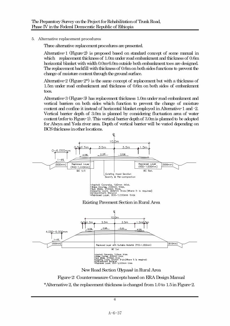
5. Alternative replacement procedures
Three alternative replacement procedures are presented. Alternative-1 (Figure-2) is proposed based on standard concept of some manual in which replacement thickness of 1.0m under road embankment and thickness of 0.6m horizontal blanket with width 0.0m-6.0m outside both embankment toes are designed. The replacement backfill with thickness of 0.6m on both sides functions to prevent the change of moisture content through the ground surface. Alternative-2 (Figure-2*) is the same concept of replacement but with a thickness of 1.5m under road embankment and thickness of 0.6m on both sides of embankment toes. Alternative-3 (Figure-3) has replacement thickness 1.0m under road embankment and vertical barriers on both sides which function to prevent the change of moisture content and confine it instead of horizontal blanket employed in Alternative-1 and -2. Vertical barrier depth of 3.0m is planned by considering fluctuation area of water content (refer to Figure-1). This vertical barrier depth of 3.0m is planned to be adopted for Abeya and Yeda river area. Depth of vertical barrier will be varied depending on BCS thickness in other locations.
Existing Pavement Section in Rural Area
New Road Section (Bypass) in Rural Area Figure-2: Countermeasure Concepts based on ERA Design Manual
*Alternative 2, the replacement thickness is changed from 1.0 to 1.5 in Figure-2.
A-6-37

The Preparatory Survey on the Project for Rehabilitation of Trunk Road, Phase IV in the Federal Democratic Republic of Ethiopia
7
Existing Road Section in Town Area
Existing Road Section in High Embankment (Rural) Area
New Road Section (Bypass) in Rural Area
Figure-3 Countermeasure Concepts Proposed by the Study Team
A-6-38

The Preparatory Survey on the Project for Rehabilitation of Trunk Road, Phase IV in the Federal Democratic Republic of Ethiopia
8
6. Recommendation
Table-4 shows advantages and disadvantages of the three Alternatives. Only Alternative-3 can be applied for countermeasure to expansive soils in Abeya and Yeda river area, therefore Alternative-3 is recommended as the most appropriate procedure on the project road.
Table-4: Comparison of replacement methods and recommendation
Replacement thickness Under
embankment No Section Carriage
way Toe
Slope protection
Application to Abeya &
Yeda
Measures to gap between existing road and widened
part
Side protection to moisture
change
Recommendation
Realignment 1m 0.6m (L; 6m) Not suitable Enough
1 Rehabilitation of existing road 1.0m 0.6m
(L; 6m) Not enough Enough
Realignment 1.5m By thickness Not suitable Enough
2 Rehabilitationof existing road 1.5m By
thickness Enough Enough
Realignment 1.0m 3.0mBy
thickness Suitable Enough 3 Rehabilitation
of existing road 1.5m By thickness Enough Enough
Recommendable
Note: The maximum thickness of soil replacement is 1.5m according to many Manuals and experiences.
A-6-39

A-6-40

The Preparatory Survey on the Project for Rehabilitation of Trunk Road, Phase IV in the Federal Democratic Republic of Ethiopia
1
Discussion for the Design Conditions and Concepts
In a series of previous meetings, following matters were left as pending issues.
- Road alignment at Chemoga - Applicable cross sections in Debre Markos Town
We hereby report results of the study based on the data of the detail topographic survey completed on 5th of November.
1. Alignment Change at Chemoga
(1) Outline of Alignment Change
Design Condition: Urban/Peri-urban
Design speed: 50km/h Min. Radius: 85m Transition curve: not required Max. Grade: 8.0% Min. Stopping Sight Distance: 55m
Table-1
Location Reasons & Interferences
Chemoga Bridge: Reuse
L=67.2m, W=7.0m
Chemoga Area: L=1.4km
Proposed route by HEC DDProposed new route
Chemoga Area
58.0 – 59.4km (L=1.4km)
Reason - To reduce the number
of affected houses
Interference - Some houses
(2) Recom mendation
New road construction would m ean a commensurate increment of affected area and houses. Although horizontal alignment is im proved by new construction road, it makes vertical alignment worse . On the other hand, existing route provided gentler grade in comparison to new road alignment. In addition, stopping sight distance for design speed of 50km/h is also satisfied. Thus up grading of ex isting route (proposed new alignment) is recommend ed as much as possible .
A-6-41

The Preparatory Survey on the Project for Rehabilitation of Trunk Road, Phase IV in the Federal Democratic Republic of Ethiopia
2
(3) Result of the Study based on Detail Topographic Data
Table-2
HEC Alignment New Alignment Min. Radius 270m 100m Max. Grade 8.0% 5.8%
Applicable design speed 50km/h 50km/h
Regulatory Speed 30 – 50km Geometric
Calculated Sight Distance 111m > 55m 68m > 55m
Applicable Cross Section
CL
No. of affected houses 3 0
Road reserve New land is required because of new road construction
Width of upgraded road will be within ex isting road reserve area. Land
required Diversion during
construction stage It is not required because of new construction road.
Diversion with 6m will be provided by use of a part of ERA’s land.
: Affected Houses
Chemoga Area L=1.4km
Chemoga Bridge: Reuse
: Check of Sight Distance
ERA'sland will be t emporarily provided as diversion during construction st age.
Figure-1 Comparative Illustration at Chemoga
A-6-42

The Preparatory Survey on the Project for Rehabilitation of Trunk Road, Phase IV in the Federal Democratic Republic of Ethiopia
3
2. Applicable Cross Sections in Debre Markos
(1) Recom mended Cross Section on Previous Meeting
Table-3
Section Plan for A3 in Debre Markos Applicable Cross Sections
L=1,200m, W=19.5m
L=1,800m, W=19.0m
L=1,100m, W=12.0m
Populat ed Area
Town Center Sect ion
Pr imary School
64.2km – 65.4km (End) CL
62.4km – 64.2km CL
61.3km – 62.4km CL
(2) Result of the Study
In report of previous m eeting, beginning point of D/Markos was set at div erging point of A3 and city road proposed by HEC. However beginning point of D/Markos was specified to be at the entrance of small village (see Table-4 in next page) in the meeting. Thus length of D/Markos section is extended from 4.1km (Sta.61.3-65.4) to 4.6km (Sta.60.8-65.4).
A-6-43
The Preparatory Survey on the Project for Rehabilitation of Trunk Road, Phase IV in the Federal Democratic Republic of Ethiopia
4
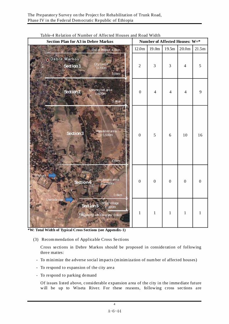
Table-4 Relation of Number of Affected Houses and Road Width Section Plan for A3 in Debre Markos Number of Affected Houses: W=*
12.0m 19.0m 19.5m 20.0m 21.5m
2 3 3 4 5
0 4 4 4 9
0 5 6 10 16
0 0 0 0 0
Beginning of D/Markos: 0.0km
Useta BridgeSmall Village
L=800m
Low density areaL=1,000m
P/School
Populated areaL=1,500m
0.8km
1.8km
3.3km
City CenterL=700m
Commercial areaL=600m
3.9km
End of Project: 4.6km
Section 1
Section 2
Section 3
Section 4
Section 51 1 1 1 1
*W: Total Width of Typical Cross Sections (see Appendix-1)
(3) Recom mendation of Applicable Cross Sections
Cross sections in Debre Markos should be proposed in consideration of following three mattes:
- To minimize the adverse social impacts (minimization of num ber of affected houses)
- To respond to expansion of the city area
- To respond to parking demand
Of issues listed above, considerable expansion area of the city in the immediate future will be up to Wiseta River. For these reasons, following cross sections are
A-6-44
The Preparatory Survey on the Project for Rehabilitation of Trunk Road, Phase IV in the Federal Democratic Republic of Ethiopia
5
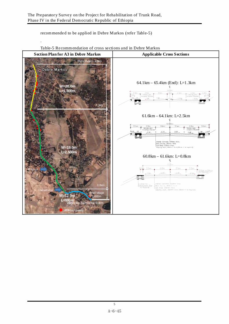
recommended to be applied in Debre Markos (refer Table-5)
.
Table-5 Recomm endation of cross sections and in Debre Markos Section Plan for A3 in Debre Markos Applicable Cross Sections
Beginning of D/Markos: 0.0km
Useta BridgeSmall Village
L=800m
P/School
Endof Project : 4.6km
3.3km
W=20.0m L=1,300m
0.8km
W=19.0m L=2,500m
W=12.0m L=800m
: Affected Houses
64.1km – 65.4km (End): L=1.3km CL
61.6km – 64.1km: L=2.5km CL
60.8km – 61.6km: L=0.8km CL
A-6-45

The Preparatory Survey on the Project for Rehabilitation of Trunk Road, Phase IV in the Federal Democratic Republic of Ethiopia
6
Appendix-1 CL
W =21.5m (Proposed by HEC DD)
CL
W=20.0m (Median Strip: 1.0m)
CL
W=19.5m (Median Strip: 0.5m)
CL
W=19.0m (No Median Strip) CL
W=12.0m
A-6-46

The Preparatory Survey on the Project for Rehabilitation of Trunk Road, Phase IV in the Federal Democratic Republic of Ethiopia
7
Appendix-2
Table: Number of Affected Houses (Whole Sections)
DD Route by HEC
Proposed New Alignment Sections Width
PAHs PAHs PAPs Sta.00+000-00+500 Dejen 12.0m 8 0 0 Sta.06+800-09+100 Yetnora 12.0m 9 0 0 Sta.18+600-20+200 Wejel 19.0m 24 1 5 Sta.28+700-30+400 Lumame 19.0m 9 5 1 0
Sta.30+400-39+300 Unpopulated Area 10.0m 3 2 8
Sta.39+300-39+900 Gudalema 12.0m 1 0 0 Sta.45+720-46+800 Amber 19.0m ND 16 70
Sta.46+800-52+000 Unpopulated Area 10.0m 1 2 10
Sta.52+000-52+900 Filiklik 12.0m ND 0 0 Sta.58+000-59+400 Chemoga 12.0m 11 0 0
Sta.59+400-60+900 Unpopulated Area 10.0m 9 0 0
Sta.60+900-61+700 12.0m 1 5 Sta.61+700-64+200 19.0m 5 24 Sta.64+200-65+500
D/Markos 20.0m
848 37
Total 159 40 159 1: Kiosk
A-6-47

A-6-48

A-6-49

A-6-50

Appendix ;
Cross section of Debre Markos Town
A-6-51

A-6-52

A-6-53
6.2 RAP 関連協議議事録

A-6-54
Ref.No.n3-138/00-16 Date 4/11/2009
From: The Amhara National Regional State Debre Markos City Administration Mayer Office To : Highway Engineering Consultants Addis Ababa Subject : Road Construction Works We refer to our letter addressed to Ethiopia Road Authority of the engineering regulatory division 19/5/2009 with Ref.No.2526/nl/00-18.In the letter we address ERA of the direction of the new road construction in Dejen town. Currently, we understand that HEC is contracted for the consultancy service of the project by a letter sent to us with Ref.No. HEC/1991/09 and dated 02/11/2009. Therefore, we request the route for the new road construction in the direction of Debre Markos district to Tekle-haimanot Square (old road). Attached here with please find a minute signed by City Mayer Committee concerning the dicision of the road al/ Route in the Debre Markos town.
Signature and Seal
Abebaw Yaynwaga Debre Markos City Mayor

A-6-55
Date 3/11/2009 Mayor’s Committee Minutes of Meeting Attendants:
1. Mr. Migbaru Kebede Mayor’s committee chairperson 2. Mr. Alemahehu Tekeste Committee Member 3. Mr. Abebaw Yaynwaga » 4. Mr. Asmamaw Atnafu » 5. Mr. Tekel Yitayew » 6. Mr. Menberu Mengistu » 7. Mr. Dereje Denekew » 8. Mr. Melesachew Demelash » 9. Mr. Kefale Adinew » 10. Mr. Yohannes Amno » 11. Mr. Belaynew Tsega » 12. Mr. Mesfin Gesesse »
Agenda: Selection of road corridor/route in Debre Markos town The Mayor’s committee has discussed and agreed on the following points:
1. The road segment in Debre Markos town should be wide and median separated and should be in accordance with the master plan. 2. The road should pass along the corridor from the Debre Markos District of ERA and Kebele 07 office and along the Mosque to the Tekle haimanot round about.
The reason for the above decision is as follows:
1. If the existing road is to be rehabilitated, it is going to be costly as there will be big volume of slope cutting and filling works. 2. The existing road horizontal alignment has many curves; therefore, number of accident will be high. 3. There are big building structures along the existing road; therefore, the amount of compensation will be extremely high. In addition, resettlement action will create an immense pressure on the people to be resettled and the city administration. 4. The terrain along the proposed alignment is more suitable for the road construction. In addition the construction of the road will bring an economic growth to all the people living along the road.
Therefore, we recommend the alignment of the road to be as agreed above for the reasons mentioned above. The above decision by the committee should be informed to the Design Firm by the name Highway Engineering Consultants PLC. The committee has already informed of its decision to ERA.
Signature of the committee members
Seal of the Debre Markos Town Administration

A-6-56
Date: 4/11/2009 Discussion to effectively carryout the Road construction Works from Dejen to Debre Markos Time: 9:30 am Place: Aneded Woreda Office Attendants
1. Mr. Abdulahi Mohammed HEC 2. Mr. Badeg Lake Representative of Agricultural Office 3. Mr. Abebaw Adane » » 4. Mr. Yalkibetal Admase Representative of Aneded Woreda Administration 5. Mr. Aderaw Abitew Land Administration Office
Agenda: Concerning families that will be affected by the Road Construction Works Mr. Abdulahi Mohammed: He said that he will make discussion concerning the compensation of farm land and houses with the concerned bodies. If a farm land or house is affected by the road works, we have to pay compensation according to the regulations. The road will have a width of 22m in towns. Mr. Abebaw Adane: How is the road construction work go along with the Reservoir? Mr. Badege Lake: Compensation must be paid for those affected by the road work. Mr. Abebaw Adane: We have to make ready of ourselves anD/Deliver what is expected of us. Eventhough the people and the administration was expecting for long time, it is disappointing that the road is no going to pass through Aneded woreda village. Since the road is not going to pass through the village, the people are not going to benefit from the road construction. Therefore, the people will be disappointed anD/Distance themselves from the government. Mr. Abdulahi Mohammed: Concerning the above, a discussion has to be made with the Designers, the Zone and Regional Offices of ERA. Mr. Badege Lake: We have to disscuss with a tangible information and we have to understand that the economic development of the village will be hindered. That is because the road is not passing through the Aneded woreda village.
Signature of the attendants
Seal of the Eastern Gojam Administration Zone
Aneded Woreda Trade & Industry Office
Date 4/11/2009

A-6-57
Preparation for necessary precautions to be taken for the Dejen Debre Markos Road Construction Project Attendants:
1. Mr. Abdulahi Mohammed HEC (Chairperson) 2. Mr. Abebe Melese Awabel Woreda Administration 3. Mr. Kumilachew Damte Environmental Protection Agency 4. Mr. Edme alem Andualem Revenue Authority Office 5. Mr. Sima Kebede Awabel Woreda Municipality 6. Mr. Azeze Kasahun Women’s Associaltion representative
Agenda:
1. Compensation Matter 2. How to consider affected people in urban and rural area
Minutes of meeting are as follows: Mr. Abdulahi Mohammed: The Government will pay compensation to properties like farm land and houses that are affected by the road construction. He requested if there is any question from the people and administration so that HEC can accommodate the matter in the study. Mr. Kumilachew Damte: According to government regulation a compensation will be paid for farmers who are affected. However property evaluation and paying the compensation money will take a very long time. So what are you thinking in this regard? Mr. Abdulahi Mohammed: compensation will be evaluated and will be paid by Ethiopian Roads Authority so it is difficult to answer this question by HEC. Mr. Azeze Kasahun: Is the road construction going to affect seriously specially the farmlands? Mr. Abdulahi Mohammed: The road alignment is almost following the existing centerline around this village. Therefore farmlands are not going to be affected seriously.
Sign by the participants
Seal of the Amhara Regional Government, Western Gojam Administration
Awabel Woreda Administration Office
Date: 4/11/2009

A-6-58
Meeting Venue: Dejen Woreda Water Resource Office Time: 2:00 pm Attendants:
1. Mr. Abdulahi Mohammod HEC 2. Mr. Birilew Mossa Environmental Protection Agency 3. Mr. Melisew Tamiru Agricultural Office 4. Mr. Abedje Asamirew General Manager Municipality 5. Mr. Tamir Adam Land Administration Office
Agenda: Concerning resettlement and compensation for the Dejen Debre Markos Road Project Minutes of Discussion Mr. Tamiru: He suggested each and every property that will be affected should be identified with a photo of the property. Mr. Melisew: For a farm land the type of crop, number of trees and productivity should be considereD/During the property evaluation stage and compensation. Mr. Birilew: Farmers who have settled recently should be compensated according to the new regulation of the government. Mr. Abeje: New construction near the road should be prohibited and the people should be informed about this. Therefore, all participants have reached on agreement on the above issues unanimously.
Signature of the participants Seal of the Amhara Regional Government, Eastern Gojam Administration
Dejen Town Municipality

A-6-59
6.3 EEPCO ダム計画
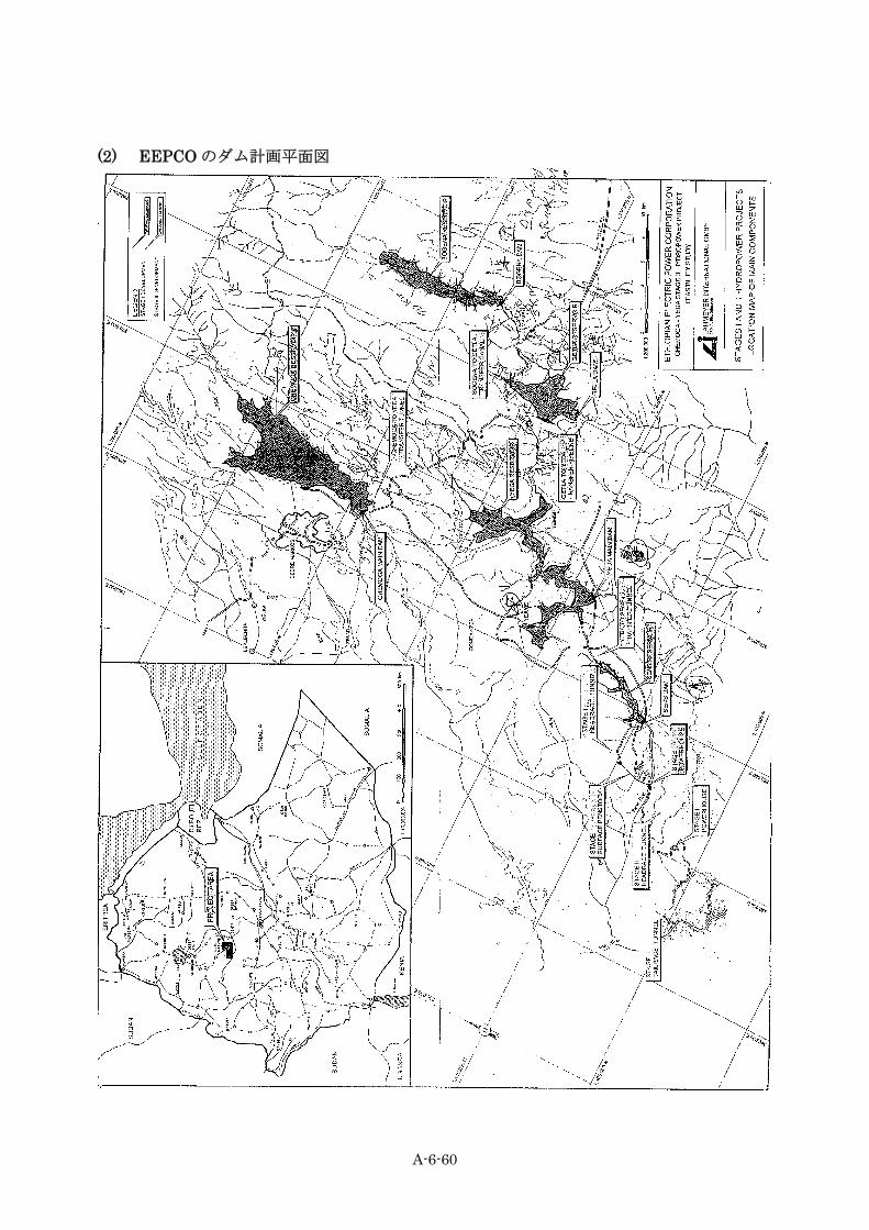
(1) 対象区間に係るダム計画 EEPCO による発電ダム計画(Chemoga Veda Project)が実施されており(2009 年 9 月 22 日契約
工期 4 年 9 カ月)、当該計画道路に係る河川の状況は図 6.3.1のとおりである。
図 6.3.1 ダム計画概要図
図 6.3.1に示すように計画は 5 ダムである。この内センスダムは計画道路にかかわらない。イエ
ダダムは 20km 以上下流にあり道路への影響は及ばない。チェモガダムは計画道路の約 300m 上流、
ボゲナダムは計画道路の約 3km 上流にあり、適切な放水計画を設定すれば計画道路への影響はな
い。 ゲトラダムについてはダム貯水池が現況道路に影響するため ERA により道路線形が 1.7km 上流
に変更された。
Chemoga Abesh Yeda Ziba Mintkat Getla Yekeyet Bogena
BOGENACHEMOGA
←Debre Markos Dejen→
Ziba
SENS YEDA GETLA Bogena
Chemoga Sens Yeda Getla
ABEYA
A-6-60
(2) EEPCO のダム計画平面図

A-6-61
(3) EEPCO のダム水路計画縦断図

A-6-62
6.4 交通量調査結果と将来予測(ERA・D/D より)
A-6-63
6.5 地質調査
(1) 地質調査
1) 調査目的と調査内容 地質調査は計画道路の施設の設計および施工上必要な地質状況の把握を目的として実施した。特
に本区間には、ブラックコットンソイルと呼ばれる膨潤性の高い粘土が分布しており、その分布、
層厚、特性を把握することを主眼としている。 本調査は次の三つの調査を含んで
いる。
ボーリング調査(基礎地盤調査と土質試験) テストピット調査(道路構成の確認とブラックコットンソイルの分布とその層厚の確 認及
び土質試料採取とそれに伴う CBR 試験) 材料調査(土取場、採石場のボーリング及びテストピットによる試料採取と土質試験)
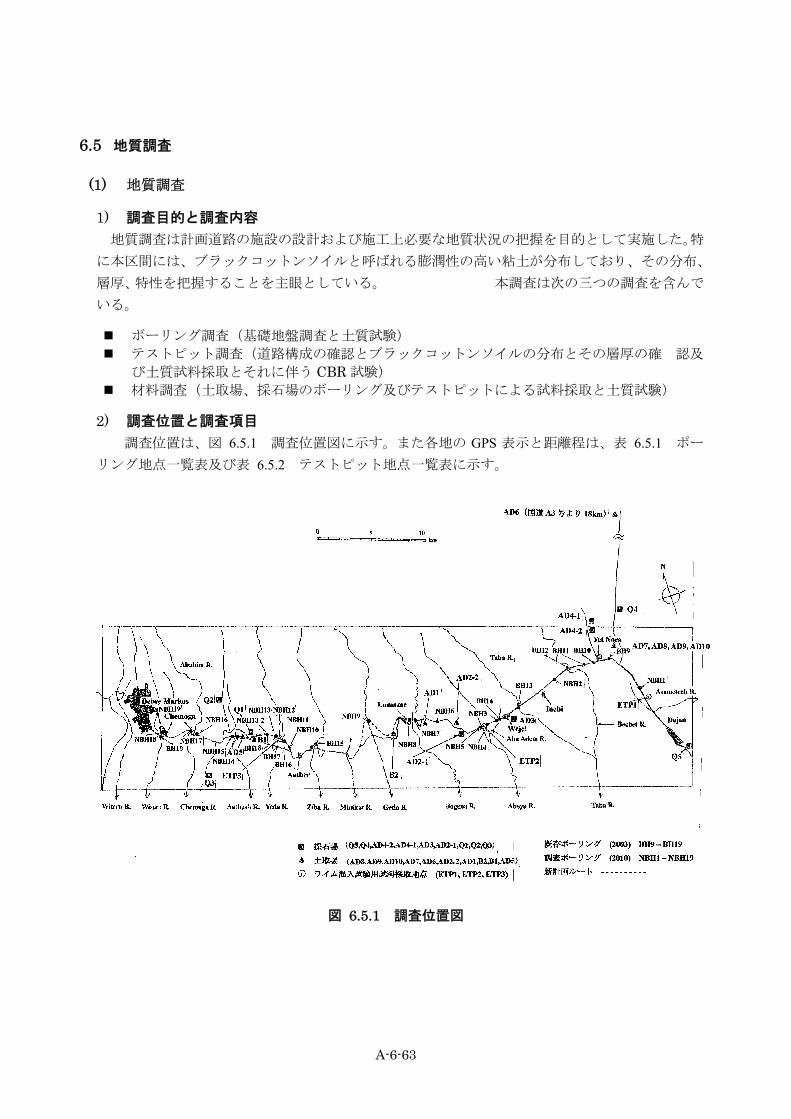
2) 調査位置と調査項目 調査位置は、図 6.5.1 調査位置図に示す。また各地の GPS 表示と距離程は、表 6.5.1 ボー
リング地点一覧表及び表 6.5.2 テストピット地点一覧表に示す。
図 6.5.1 調査位置図
A-6-64
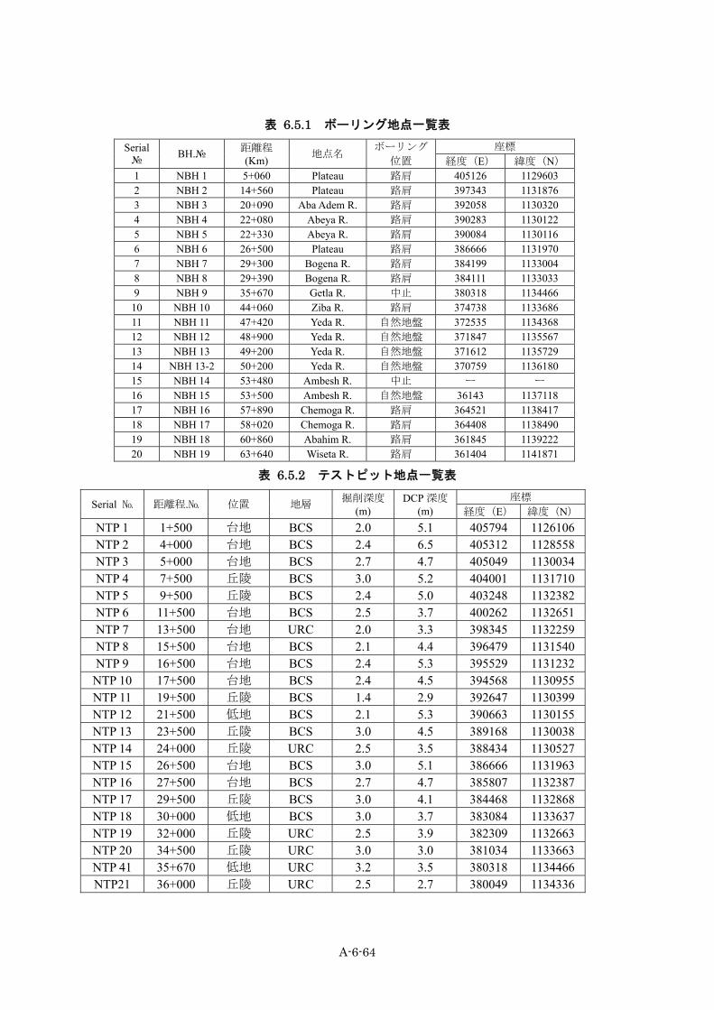
表 6.5.1 ボーリング地点一覧表 Serial № BH.№ 距離程
(Km) 地点名 ボーリング
位置 座標
経度(E) 緯度(N) 1 NBH 1 5+060 Plateau 路肩 405126 1129603 2 NBH 2 14+560 Plateau 路肩 397343 1131876 3 NBH 3 20+090 Aba Adem R. 路肩 392058 1130320 4 NBH 4 22+080 Abeya R. 路肩 390283 1130122 5 NBH 5 22+330 Abeya R. 路肩 390084 1130116 6 NBH 6 26+500 Plateau 路肩 386666 1131970 7 NBH 7 29+300 Bogena R. 路肩 384199 1133004 8 NBH 8 29+390 Bogena R. 路肩 384111 1133033 9 NBH 9 35+670 Getla R. 中止 380318 1134466
10 NBH 10 44+060 Ziba R. 路肩 374738 1133686 11 NBH 11 47+420 Yeda R. 自然地盤 372535 1134368 12 NBH 12 48+900 Yeda R. 自然地盤 371847 1135567 13 NBH 13 49+200 Yeda R. 自然地盤 371612 1135729 14 NBH 13-2 50+200 Yeda R. 自然地盤 370759 1136180 15 NBH 14 53+480 Ambesh R. 中止 ー ー 16 NBH 15 53+500 Ambesh R. 自然地盤 36143 1137118 17 NBH 16 57+890 Chemoga R. 路肩 364521 1138417 18 NBH 17 58+020 Chemoga R. 路肩 364408 1138490 19 NBH 18 60+860 Abahim R. 路肩 361845 1139222 20 NBH 19 63+640 Wiseta R. 路肩 361404 1141871
表 6.5.2 テストピット地点一覧表
Serial № 距離程.№ 位置 地層 掘削深度 (m)
DCP 深度 (m)
座標 経度(E) 緯度(N)
NTP 1 1+500 台地 BCS 2.0 5.1 405794 1126106 NTP 2 4+000 台地 BCS 2.4 6.5 405312 1128558 NTP 3 5+000 台地 BCS 2.7 4.7 405049 1130034 NTP 4 7+500 丘陵 BCS 3.0 5.2 404001 1131710 NTP 5 9+500 丘陵 BCS 2.4 5.0 403248 1132382 NTP 6 11+500 台地 BCS 2.5 3.7 400262 1132651 NTP 7 13+500 台地 URC 2.0 3.3 398345 1132259 NTP 8 15+500 台地 BCS 2.1 4.4 396479 1131540 NTP 9 16+500 台地 BCS 2.4 5.3 395529 1131232
NTP 10 17+500 台地 BCS 2.4 4.5 394568 1130955 NTP 11 19+500 丘陵 BCS 1.4 2.9 392647 1130399 NTP 12 21+500 低地 BCS 2.1 5.3 390663 1130155 NTP 13 23+500 丘陵 BCS 3.0 4.5 389168 1130038 NTP 14 24+000 丘陵 URC 2.5 3.5 388434 1130527 NTP 15 26+500 台地 BCS 3.0 5.1 386666 1131963 NTP 16 27+500 台地 BCS 2.7 4.7 385807 1132387 NTP 17 29+500 丘陵 BCS 3.0 4.1 384468 1132868 NTP 18 30+000 低地 BCS 3.0 3.7 383084 1133637 NTP 19 32+000 丘陵 URC 2.5 3.9 382309 1132663 NTP 20 34+500 丘陵 URC 3.0 3.0 381034 1133663 NTP 41 35+670 低地 URC 3.2 3.5 380318 1134466 NTP21 36+000 丘陵 URC 2.5 2.7 380049 1134336

A-6-65
Serial № 距離程.№ 位置 地層 掘削深度 (m)
DCP 深度 (m)
座標 経度(E) 緯度(N)
NTP22 37+500 丘陵 BCS 2.7 1.9 379460 1133045 NTP23 38+500 丘陵 BCS 2.7 2.9 405312 1128557 NTP24 40+500 丘陵 URC 2.2 2.4 377275 1131559 NTP25 42+500 丘陵 URC 3.0 4.8 375867 1132737 NTP26 43+500 丘陵 URC 1.5 0.6 374888 1133305 NTP27 45+000 丘陵 URC 2.5 1.5 373855 1133439 NTP28 46+500 丘陵 URC 2.5 3.8 372682 1133218 NTP29 48+000 低地 BCS 3.0 4.2 372449 1134930 NTP30 49+500 低地 UBC 2.4 4.1 371094 1135753 NTP31 50+500 丘陵 BCS 2.7 2.0 370494 1136336 NTP32 51+500 丘陵 URC 2.4 2.0 369608 1136339 NTP33 53+000 丘陵 URC 1.8 4.0 369607 1137014 NTP34 55+000 丘陵 URC 1.0 2.1 366762 1136787 NTP35 56+500 丘陵 URC 1.8 2.5 365900 1137161 NTP36 57+500 丘陵 URC 2.0 4.9 364841 1138197 NTP37 59+000 丘陵 URC 3.0 1.5 363493 1138706 NTP38 60+500 台地 URC 2.5 4.7 362131 1139006 NTP39 62+000 台地 URC 2.8 4.2 361868 1140312 NTP40 63+000 台地 URC 2.6 3.8 381429 1141731
BCS = ブラックコットンソイル/URC = 上部赤色粘土/UBC = 上部褐色粘土(沖積土)
調査内容は、次の通りである。
全ルートのブラックコットンソイルの分布状況の踏査(63km) 代表的なブラックコットンソイル分布区間のボーリング調査(3 孔) イエダ川、アベヤ川洪水区間のボーリング調査(6 孔) 調査対象橋梁のボーリング調査(9 橋梁、11 孔) ブラックコットンソイル調査のためのテストピットと DCP 試験(44 ヶ所) CBR 調査のためのサンプリング(10 ヶ所) 採石場調査のためのボーリングとサンプリング(5 ヶ所、2 孔) 土取場調査のためのテストピットとサンプリング(8 ヶ所、21 試料) 採取試料の土質試験一式
3) 調査数量 調査数量は、表 6.5.3 ボーリング及び土質試験数量 ( デジェン-デブレマルコス)、表 6.5.4 テ
ストピット及び土質試験数量表、表 6.5.5~表 6.5.7 材料調査及び土質試験一覧表に示す。なお、
ボーリング調査のうち、ゲトラ川の NBH9は、アクセス道路がなく、かつ雨季のため搬入が著し
く困難なため DCP で代用した。また、アンベシュ川の NBH14 は両岸に岩盤が露出しており、地
質状況が明らかなため、NBH15 のみの削孔とし、中止した。

A-6-66
表 6.5.3 ボーリング及び土質試験数量 ( デジェン-デブレマルコス)
B. H。№ 位置 (m) 深度 (m)
貫
入
試
験
不
撹
乱
試
料
比
重
含
水
比
粒
度
液
性
塑
性
一
軸
圧
縮
三
軸
圧
縮
圧
密 収
縮 岩
石
NBH1 Plateau Area 10.0 8 2 2 2 2 2 1 0 1 1 0 NBH2 Plateau Area 10.0 8 2 2 2 2 2 1 1 1 1 0 NBH3 Aba Adem R. 10.0 7 2 1 1 1 1 0 1 1 2 0 NBH4 Abeya R. 27.2 23 2 13 13 13 12 0 1 1 2 1 NBH5 Abeya R. 26.6 23 1 1 1 1 1 0 0 0 0 0 NBH6 Plateau Area 8.0 5 1 1 1 1 1 1 0 1 1 0 NBH7 Bonega R. 7.0 3 1 1 1 1 1 0 0 0 0 1 NBH8 Bonega R. 7.2 2 1 1 1 1 1 0 0 0 0 0 NBH9 Getla R.(中止) - - - - - - - - - - - -
NBH10 Ziba R. 12.2 8 2 2 2 2 2 1 1 1 1 0 NBH11 Yeda R. 27.0 25 2 2 2 2 2 1 1 0 1 0 NBH12 Yeda R. 30.0 25 2 2 2 2 2 1 1 1 1 1 NBH13 Yeda R. 31.2 30 2 17 17 17 16 1 1 1 1 0
NBH13-2 Yeda R. 20.0 15 1 1 1 1 1 1 1 0 1 0 NBH14 Ambesh R. (中止) - - - - - - - - - - - - NBH15 Ambesh R. 6.5 1 0 0 0 0 0 0 0 0 0 0 NBH16 Chemoga R. 6.9 2 1 1 1 1 1 0 0 0 0 0 NBH17 Chemoga R. 6.6 2 1 1 1 1 1 0 0 0 0 0 NBH18 Abahim R. 18.0 15 1 1 1 1 1 1 0 0 0 0 NBH19 Wiseta R. 8.0 0 0 0 0 0 0 0 0 0 0 1
Total 272.4 202 24 49 49 49 47 9 8 8 12 4
表 6.5.4 テストピット及び土質試験数量表 試掘数量 比重 含水比 粒度 液性塑性 収縮 CBR 現場密度 DCP
40 10 10 50 50 10 10 10 40
表 6.5.5 採石場ボーリング及び土質試験数量表 地点 No. 種別 密度と吸水率 安定性 ロサンジェルステスト 破砕テスト AD 2-1 サンプリング 1 1 1 1 AD 4-2 ボーリング( 10m ) 1 1 1 1
Q 4 ボーリング( 10m ) 1 1 1 1 Q 5 サンプリング 1 1 1 1
AD 6 サンプリング 1 1 1 1 計 5 5 5 5
表 6.5.6 土取場テストピット、サンプリング及び土質試験数量表
地点 No. 種別 粒度 (沈降)
液性塑性 線収縮 CBR
( 3 点 ) 透水試験
B 2 サンプリング 2 2 2 2 0 AD 1 Test Pit ( H : 5 m ) 2 2 2 2 1
AD 2-2 Test Pit ( H : 3 m ) 1 1 1 1 0 AD 6 サンプリング 2 2 2 2 1 AD 7 サンプリング 3 3 3 3 0 AD 8 サンプリング 1 1 1 1 0 AD 9 サンプリング 1 1 1 1 0 AD 10 サンプリング 2 2 2 2 0 計 14 14 14 14 2
(注)透水試験は、上記の 2 試料のほか参考としてブラックコットンソイル、赤色土等で 13 試料、計 15 試料につ
いて実施した。

A-6-67
表 6.5.7 ライム混入試料の CBR テスト
既存 新 TP No.
距離程 (km) 位置 経度
(E) 緯度
(N)ライム
2% ライム
4% ライム
6% 計
NTP 2 ETP 1 4+000 Dejen 405312 1128558 2 2 2 6 NTP 13 ETP 2 23+000 Abeya R. 389168 1130038 2 2 2 6 NTP 30 ETP 3 49+000 Yeda R. 371094 1135753 2 2 2 6
計 - - - - - 6 6 6 18
4) 調査地の地形地質概要 図 6.5.2にエチオピアの地質図を示す。エチオピアはその国土の中央部を南西から走るアフリ
カ大地溝帯によって西部と東部に二分されている。このアフリカ大地溝帯は南のモザンピークから
タンザニア、ケニアを経てエチオピアに至る幅 50~100km、延長 6.000kmに達する大地溝帯で
ある。アフリカ大地溝帯は第三紀以降主にケニアとエチオピアを中心として隆起運動が開始され、
現在までの隆起量は 2.000~3.000mに達している。
図 6.5.2 エチオピア地質図
この隆起運動とほぼ同時に隆起帯の中心部が陥没して現在の地溝帯が形成されると共に、割れ目
噴火による膨大な玄武岩の流出が行われた。現在でもこの活動は続いており、地溝帯中は多数の活
火山が分布し、小規模な地震も各所で発生している。また地溝帯の中心部には、陥没によって形成
された多数の湖が南北に配列している。エチオピアでの玄武岩の流出は大地溝帯中で最大規模を示
し、幅 500km、長さ 1.000kmにわたるエチオピア台地を形成した。エチオピア台地の標高は 2.000m~2.500mを示し、大地溝帯中で最も高い。溶岩流の層厚は台地内部では数 100mにすぎないが、

A-6-68
周縁部では 2.000m以上に達している。一方、エチオピアの地震活動や火山活動はタンザニアやケ
ニアに比較して低調であり、台地の内部では殆ど発生していない。大地溝帯の北端は首都アディス
アベバ付近で扇状に開き、その東端はアデン湾に接してアデン湾地溝帯に、西端は紅海に接して紅
海地溝帯に連続する。この扇状の三角地帯はアファー凹地と呼ばれ、3本の地溝帯が交差する複雑
な地質構造を示し、エチオピアの地震活動と火山活動はほぼこの地に集中している。エチオピア台
地の基盤を構成するのは、中生代の海成堆積岩類で主として砂岩、頁岩、泥岩、石灰岩などからな
る。これらの各層はほぼ水平に堆積しており、台地内部では、厚さ 300~400mの玄武岩層に覆わ
れている。台地面は比高 50~100mの傾斜の緩い丘陵と平坦面の組み合わせからなり、丘陵は幅数
kmの谷底平野によって分断されている。丘陵部には玄武岩が露出し、その表面は、熱帯赤土によ
って覆われている。谷底平野には玄武岩の強風化によって生成された無機質のブラックコットンソ
イルが沖積土として分布している。ブラックコットンソイルは東アフリカの玄武岩地帯に広く分布
し、綿花や穀類の栽培には適しているが、乾季には収縮し、雨季には膨潤が著しく、土工には不適
な土壌である。アディスアベバ北西約 300kmの台地上にはエチオピア最大の湖 タナ湖(南北 75km、東西 60km、標高 1.830m)が存在する。タナ湖からは、アバイ川(青ナイル川)が流出し、
スーダンで白ナイル川と合流し、ナイル川となってエジプトへ流入している。アバイ川は、台地中
央部では隆起運動と共に下方浸食が拡大し、基盤岩まで深く切り込み河床よりの比高約 1.500mの
大峡谷を形成している。エチオピア台地全体は緩く西側に傾斜しており、このため台地上の殆どの
河川はアバイ川をはじめとしてナイル水系の支流となっている。調査区間であるデジェン~デブレ
マルコス間の約 63kmはアバイ峡谷の西側の玄武岩台地上に位置している。
5) 調査ルートの地質状況 本区間はエチオピア台地のほぼ中心部に位置し、台地面は南西~緩く傾斜しており、デジェン
の標高は約 2.500m、西へ約 63km離れたデブレマルコスの標高は約 2.400mを示す。台地上の河
川は谷を刻みつつ、調査ルートに直交して南流しアバイ川に合流する。主要な河川は、東から西へ、
アサマテッチ川、ベケット川、タバ川、アバアデム川、アベヤ川、ボゲナ川、ゲトラ川、ジバ川、
イエダ川、アンベッシュ川、チェモガ川、アバヒム川、ウセタ川の計 13 河川である。本区間は台
地上には比高 100~150m程度の集落を載せた丘陵が南北方向に 5 列存在する。上記河川のうちア
ベヤ川、ゲトラ川、ジバ川、イエダ川の 4 河川はこれらの丘陵の間に幅 1~3kmの谷底平野を形
成しており、このうちアベヤ川とイエダ川が最も広い。丘陵部は、主として玄武岩の岩盤とそれを
覆う厚さ数 m の赤色土が分布している。台地(浸食平坦面)や谷底平野には褐色土が分布し、そ
の下部にブラックコットンソイルが分布する。ブラックコットンソイルは、谷底平野で厚く 10mに達し、台地上では 2~3m程度である。 本区間に分布する地層は、次の通りである。
上部褐色粘土~シルト(UBC) 主として谷底平野の氾濫原に分布し、部分的に台地上の凹地に薄く分布する。層厚は 1~3mで
河川流出による沖積堆積物である。 本層は粘土質シルトで軟弱である。

A-6-69
上部赤色粘土~シルト(URC) 主として丘陵頂部から斜面に分布する赤色~赤褐色を呈する粘土質シルトで部分的に玄武岩礫
を混入する。本層は玄武岩の強風化によって生じたものが、降水やソリフラクションによって移動
して二次堆積したものである。本層は上部褐色粘土に比較して締まりは良好である。層厚は 2~3m程度であるが、斜面下部では 5~6mに達する場合もある。
ブラックコットンソイル(BCS) 主として台地面と谷底平野の氾濫原に分布する。黒色~黒灰色を呈する粘土質シルトである。層
厚は台地部で 2~3m、谷底平野特にアベヤ川・イエダ川では約 10mに達する。本層は丘陵部頂部
には分布しないが斜面下部では赤色土がブラックコットンソイル化している部分も認められる。雨
季には膨潤化するが、乾季には収縮してひび割れ状を呈する。
下部粘土(LC) 主として谷底平野のブラックコットンソイルの下位に分布し、部分的に台地の凹地にわずかに分
布する。本層は灰色を呈する硬質粘土である。層厚は、アベヤ川、イエダ川で 12~17mに達し台
地下部では 2~3m程度である。
残留風化土(RS) 主として丘陵部の赤色土の下位に分布する。灰色~黄灰色を呈し、礫を混入する場合もある。本
層は玄武岩が原位置で風化したものである。全体として砂質シルト~シルト質砂状で固結して極め
て硬い。層厚は場所による変化が著しく 2~8m程度である。
凝灰岩(TF) 本層は上位赤色土又は風化残留土の下位に分布し、アバアデム川及びイエダ川右岸に分布する。
本層は黄灰色~灰緑色を呈したシルト質の軟岩である。露頭では明瞭な層理を有し、固結度も高い。
層厚は 2~10m程度と推定される。
変質玄武岩(DB a) 強風化玄武岩で径 2~10cmの玄武岩の角礫と風化粘土が混在する礫層である。礫の含有率の高
い部分は、支持層として十分な強度を持つが、粘土分が多い場合は支持層としては不適である。層
厚は変化が激しいが、およそ 5~10m程度である。
玄武岩(B a) 黒色~黒灰色の堅硬緻密な玄武岩であり、本区間の基盤岩である。露頭では、柱状節理を持つも
のと多孔質で塊状のものの 2 タイプが認められるが、ボーリングコアでは、いずれも新鮮で堅硬な
ものが確認された。

A-6-70
6) 標準貫入試験結果 標準貫入試験試験結果を 表 6.5.8に示す。
表 6.5.8 標準貫入試験結果(SPT)
地層名 試験 回数 最大値 ( 回/30cm) 最小値( 回/30cm) 平均値 ( 回/30cm)
上部褐色シルト(UBC) 6 9 1 5 上部赤色シルト(URC) 6 19 2 13 ブラックコットン ソイル (BCS)
43 11 2 7
下位粘土 (LC) 80 18 5 12 風化残留土 (RS) 30 50 9 28
凝灰岩 (TF) 5 50 50 50 変質風化玄武岩 (DBa) 12 50 25 41
玄武岩(Ba) 8 反発 50 50
上表によれば最も低い N 値を示すのは上位褐色シルトである。上位赤色シルトは、沖積堆積物
である褐色シルトに比較して高い N 値を示し、ことに礫混じりの部分の N 値は高い。なお N 値 2を示すのは、例外的な強風化部である。ブラックコットンソイルの N 値は殆ど 10 以下の値を示す。
下位粘土は、固結の進んだ硬質粘土であり、N 値 5 を示すのは極所的な強風化部である。風化残留
土は、シルト質~砂質であり全体として他の上位地層に比して著しく N 値は高い。凝灰岩は軟岩
ではあるが、すべての N 値は 50 以上を示し、支持層として問題はない。玄武岩礫と風化粘土の混
在する変質玄武岩も殆ど N 値 50 以上を示すが、粘土分の含有量の高いものは 50 以下であり、支
持層としてはやや問題がある。玄武岩は、貫入時に反発するか、またはすべて 50 以上のものであ
り、支持層としては全く問題ない。
7) 地下水調査結果 表 6.5.9に地下水調査結果を示す。 ボーリングを実施した全 18 本のうち、台地平坦面上に位置する NBH1、NBH2、NBH6では
地下水位は確認されていない。上記3地点のうち NBH1、NBH2では深度 5~6m付近で風化残留
土、NBH6では深度約 6mで玄武岩に到達している。これらの3地点の位置する台地平坦面上では、
地下水位はボーリング深度以深(10m以上)にあると思われる。他のボーリングはいずれも橋梁予
定地点付近の現道の路肩で実施している。河川にはいずれも十分な流水があり、地下水位は河川水
位と平衡していると考えれば、ボーリングの地下水位はボーリング地点の地盤から河川水位までの
深度となり、現況とほぼ一致する。また、アベヤ川は現道の盛土がほぼ 1mなので地下水位は、洪
水時の水位(現地盤)と一致している。また、イエダ川は自然地盤上のボーリングであるが、地下
水位は河川水位より、やや高い程度である。アンベシュ川は河道に極めて近い自然地盤上のボーリ
ングのため、浅い地下水位となっている。なお、丘陵上では、ボーリングを実施してないが、玄武
岩で構成されているため、地下水位は、裂罅水となり、深いものと推定される。

A-6-71
表 6.5.9 ボーリング孔内地下水位測定結果 ボーリング№ 位置 深度(m) 測定日
1 Plateau なし 29-Jul-10 2 Plateau なし 30-Jul-10 3 Aba Adem R. -5.6 31-Jul-10 4 Abeya R. -1.0 07-Aug-10 5 Abeya R. -1.0 07-Aug-10 6 Plateau なし 31-Jul-10 7 Bogena R. -1.8 04-Aug-10 8 Bogena R. -1.6 05-Aug-10 9 Getla R. 削孔中止 ― 10 Ziba R. -6.0 05-Aug-10 11 Yeda R. -0.9 20-Aug-10 12 Yeda R. -1.7 14-Aug-10 13 Yeda R. -1.2 12-Aug-10
13-2 Yeda R. -1.4 25-Aug-10 14 Ambesh R. 削孔中止 ― 15 Ambesh R. -0.1 25-Aug-10 16 Chemoga R. -1.5 07-Aug-10 17 Chemoga R. -2.4 08-Aug-10 18 Abahim R. -3.4 11-Aug-10 19 Wiseta R. -1.8 12-Aug-10
8) ブラックコットンソイルの分布と層厚 ブラックコットンソイル分布と層厚は、地表踏査、ボーリング、テストピット及びオーガーボー
リングに代わる DCP(ダイナミックコーンペネトロメーター)の結果に基いて決定した。表 6.5.10にテストピットによる地層観察結果と DCP による換算 N 値 10 以下の深度を示した。また表 6.5.11にはこれらの結果に基いた各区間毎の地層(盛土、上位褐色粘土又は赤色粘土、ブラックコットン
ソイル、下位粘土)の層厚を示している。これらの地層は地形の変化に伴いその層厚を変化させる。
デジェンアベヤ川(台地と緩い斜面)約 21km区間、層厚 2.0~3.0m アベヤ川(谷底平野)約 3km区間、深度 5.0~11.0m 層厚 10.0~11.0m アベヤ川―ルマメ(丘陵間の谷底平野)約 5km区間、層厚 2.0~3.0m ゲトラ川右岸付近(台地と緩い斜面)約 1km区間、層厚 1.5~2.0m イエダ川(谷底平野)約 3km区間、層厚 5.0~10.0m 以上のようにブラックコットンソイルの層厚の最も厚いのはアベヤ川とイエダ川の谷底平野で
あり、いずれも 10mを超える。また、台地平坦面、小規模な丘陵間の谷底平野及び丘陵の下部斜
面には、層厚 1.5~3.0m程度のブラックコットンソイルが部分的に分布する。なお、イエダ川~デ
ブレマルコス間は丘陵であり、ブラックコットンソイルは全く分布しない。またデブレマルコスは
台地上に位置するが、ブラックコットンソイルは分布していない。

A-6-72
表 6.5.10 テストピットにおけるブラックコットンソイル(BCS)の深度
TP No. 地層名 BCS 深度 (TP)(m)
BCS 深度 (DCP)(m)
N<10
BCS 深度 (ボーリング)
N<10
推定深度 (m)
1 BCS 2.00 3.31 2.5 2 BCS 2.40 2.12 2.5 3 BCS 1.90 1.79 2.50(NBH1) 2.5 4 BCS 2.30 2.55 2.5 5 BCS 2.40 2.84 2.5 6 BCS,LC 3.00 0.00 6.00(NBH2) 3.2 7 URC 2.50 1.13 - 8 BCS 2.50 0.85 2.5 9 BCS 2.40 2.11 2.5 10 BCS 2.40 2.81 2.5 11 BCS 2.40 0.71 3.50(NBH3) 2.5 12 BCS 2.40 2.17 10.00(NBH4.5) 10.0~11.0 13 BCS 3.00 2.65 3.0 14 BCS 2.50 0.00 2.5 15 BCS,LC 3.00 2.32 5.90(NBH6) 3.0 16 BCS 2.70 2.27 2.8 17 BCS 3.00 1.40 3.90(NBH7.8) 3.2 18 BCS 3.00 1.89 3.0 19 URC 3.00 0.53 - 20 URC 3.00 1.50 - 21 URC 2.40 0.00 - 22 BCS 1.40 1.60 1.4 23 BCS 2.70 0.80 2.8 24 URC 2.20 0.00 - 25 URC 3.00 0.00 - 26 URC 1.50 0.57 - 27 URC 2.40 0.00 - 28 URC 2.40 0.00 - 29 BCS 3.00 - 5.50(NBH11) 5.0 30 BCS 2.40 0.55 10.00(NBH12.13) 10.0 31 BCS 2.70 0.72 2.4(NBH13-2) 2.5 32 URC 2.40 0.78 - 33 URC 1.80 1.56 - 34 URC 1.00 0.00 - 35 URC 1.80 1.49 - 36 URC 2.00 0.00 - 37 URC 3.00 0.00 - 38 URC 2.50 0.00 - 39 URC 2.80 1.59 - 40 URC 2.60 0.00 -

A-6-73
表 6.5.11 第四紀層の層厚 (デジェンデブレマルコス)
位置 距離程(km)
層厚 (m) 計 (m) 基盤
盛土 上位粘土
ブラック
コットン
ソイル 下位
Dejen 0+000 0.8 0.0 0.0 0.0 0.8 玄武岩 0+450 0.8 0.0 0.0 0.0 0.8 玄武岩 1+600 0.8 0.0 1.5 0.0 2.3 玄武岩 2+200 0.8 0.0 0.0 0.0 0.8 玄武岩 3+200 0.8 0.0 2.0 0.0 2.8 玄武岩 6+200 0.8 0.0 1.7 3.0 5.5 風化残留土 6+700 0.8 0.0 1.5 3.0 5.3 玄武岩 8+500 0.0 1.5 2.0 0.0 3.5 玄武岩 10+300 0.5 0.0 2.5 0.0 3.0 玄武岩 10+800 0.5 0.0 1.2 0.5 2.2 変質玄武岩 11+200 0.5 1.0 0.0 0.0 1.5 変質玄武岩
Bechet R. 12+400 0.5 0.0 2.5 0.0 3.0 玄武岩 14+300 0.7 0.7 0.0 0.0 1.4 変質玄武岩 18+000 0.8 0.0 1.5 3.0 5.3 変質玄武岩
Taba R. 18+300 2.0 0.0 3.0 4.8 9.8 変質玄武岩 19+900 0.5 0.0 2.0 0.0 2.5 変質玄武岩
Aba Adem R. 20+200 0.5 0.0 3.0 3.0 6.5 凝灰岩 21+300 0.5 0.0 1.5 1.5 3.5 変質玄武岩
Abeya R. 22+400 1.0 0.0 10.0 13.0 24.0 変質玄武岩 23+200 0.5 0.0 1.5 0.0 2.0 変質玄武岩 24+200 0.5 1.0 1.0 0.0 2.5 変質玄武岩 25+800 0.5 0.5 0.0 0.0 1.0 変質玄武岩
(Marsh) 26+700 0.5 0.0 2.0 3.5 6.0 玄武岩 27+300 0.5 0.5 0.0 0.0 1.0 玄武岩
(Marsh) 27+650 0.7 0.0 2.0 0.0 2.7 玄武岩 29+200 0.5 1.0 0.0 0.0 1.5 変質玄武岩
Bogena R. 29+700 1.0 0.0 3.0 0.0 4.0 玄武岩 Lumame 30+700 0.5 0.0 1.5 0.0 2.0 玄武岩
32+700 0.0 3.0 0.0 0.0 3.0 玄武岩 Getla R. 35+630 0.0 3.0 0.0 0.0 3.0 玄武岩
36+900 0.0 3.0 0.0 0.0 3.0 玄武岩 37+900 0.0 0.0 1.5 0.0 1.5 変質玄武岩 38+640 0.0 2.0 0.0 0.0 2.0 変質玄武岩 37+700 0.0 1.0 2.2 0.0 3.2 変質玄武岩 40+260 0.5 3.0 0.0 0.0 3.5 変質玄武岩 41+060 0.0 2.2 0.0 0.0 2.2 玄武岩 42+640 0.5 3.0 0.0 0.0 3.5 玄武岩 42+980 0.0 4.0 0.0 0.0 4.0 玄武岩 43+500 0.0 3.0 0.0 0.0 3.0 玄武岩
Ziba R. 44+000 0.9 5.1 0.0 0.0 6.0 風化残留土 46+260 0.5 5.0 0.0 0.0 5.5 風化残留土 46+880 0.0 3.0 0.0 0.0 3.0 玄武岩
Yeda R. 48+420 0.0 0.0 5.5 13.5 19.0 変質玄武岩 Yeda R. 49+500 0.0 2.0 8.0 18.0 28.0 玄武岩 Yeda R. 49+800 0.0 2.0 4.0 14.0 20.0 玄武岩
50+140 0.0 2.0 1.0 1.0 4.0 風化残留土 50+340 0.0 2.0 2.0 0.0 4.0 風化残留土 50+660 0.0 1.5 1.0 0.0 2.5 風化残留土 51+420 0.0 1.5 0.0 0.0 1.5 風化残留土 55+020 0.0 2.0 0.0 0.0 2.0 玄武岩 57+100 0.0 1.5 0.0 0.0 1.5 玄武岩 60+820 0.5 3.0 0.0 0.0 3.5 玄武岩
Abahim R. 60+920 4.0 5.5 0.0 6.0 15.5 風化残留土 Debre M. 64+880 0.0 3.0 0.0 0.0 3.0 変質玄武岩

A-6-74
9) 架橋地点の地質状況 アバアデム川地点(NBH 3) アバアデム川は、台地上を流れる小河川である。両岸には、上位より層厚 3.5mのブラックコッ
トンソイル、層厚 2.6mの下位粘土が分布する。深度 6.1m以深は N 値 50 以上を示す凝灰岩であり、
支持層として問題ない。
アベヤ川地点(NBH4、NBH5) アベヤ川は、谷幅約 2~3kmの谷底平野を形成している。左岸を構成するのは上位より凝灰岩、
変質玄武岩及び玄武岩である。凝灰岩は N 値 50 以上を示す良好な岩盤である。右岸及び谷底の基
盤を構成するのは変質玄武岩であり、最上部は粘土質及び礫質の強風化部であるが、下位では十分
な強度を有している。但し地表からの深度は約 23mである。谷底平野は、第 4 紀の河床堆積物で
埋積されており、上位は層厚約 10~11mのブラックコットンソイル、下位は層厚 12~13mの礫混
じりの下位粘土からなる。ブラックコットンソイルは N 値 10 以下の軟弱層であり、盛土による圧
密沈下の可能性がある。下位粘土は N 値 10 以上の硬質粘土である。
ボゲナ川地点(NBH7、NBH8) ボゲナ川は、谷幅約 1kmの谷底平野を構成している。谷底には層厚 3.9mのブラックコットン
ソイルが堆積しているが、深度 3.9m以深は N 値 50 以上の新鮮な玄武岩が分布しており、支持層
として十分な強度をもっている。
ゲトラ川地点(NBH9-削孔中止) 本地点は、現道より約 1.7km上流に位置する。アクセス道路がなく、両岸は耕作地からなると
共に両側丘陵より支流が合流しており、ボーリングマシンの運搬が困難なため、削孔を中止した。
架橋地点の地表踏査によれば、河川は、河道から比高 3mの赤色シルト層を刻んで流下しており、
河床底には、強風化の玄武岩が認められる。なおボーリングマシンに代わって DCP(ダイナミッ
クコーンペネトロメーター)による調査を実施した。調査結果によれば深度3mで換算 N 値50
の強風化玄武岩に達した。但し本層は著しく風化がすすんでおり支持層はこれより2~3m下位の
新鮮岩とするのが望ましい。
ジバ川地点(NBH10) 本地点には、地表より厚さ 6mの上位赤色粘土が分布する。本層は礫混じりで N 値 10 以上の高
い値を示すが、下位の風化残留土が N 値 10 以下の低い値を示す。基盤岩は、深度 9.2m以深が新
鮮な N 値 50 以上の玄武岩であり、支持層として十分な強度を有す。
イエダ川地点(NBH11、NBH12、NBH13,NBH13-2) イエダ川は、谷幅約 3kmの谷底平野を形成している。左岸を構成するのは、変質玄武岩とその
下位の N 値 50 以上の新鮮堅硬な玄武岩でこれらは、赤色粘土に覆われている。右岸を構成するの
は、N 値 40 以上の風化残留土と N 値 50 以上の凝灰岩である。これらも、左岸同様赤色粘土に覆
われている。谷底平野は、第四紀の河床堆積物で埋積され、上位より、層厚 2~3mの軟弱な褐色
シルト(N 値 10 以下)、層厚 10mのブラックコットンソイル(N 値 10 以下)、層厚 16~18mの硬
質な下位粘土(N 値 10~15)から構成される。このうち上位褐色シルトとブラックコットンソイ
ルは盛土による圧密沈下の可能性がある。これらの基底には、基盤岩として N 値 50 以上の変質玄
武岩が分布する。

A-6-75
アンベッシュ川地点(NBH15) アンベッシュ川は、丘陵部を開析して流れる小河川で、明瞭な谷底平野を形成していない。架橋
予定地点では、両岸に堅硬な玄武岩が深度 2mの浅所に分布しており、支持層として全く問題ない。
チェモガ川地点(NBH16、NBH17) チェモガ川は架橋地点では幅約 300mの浸食段丘を開析して流下している。段丘面は層厚 3.0~
3.7mの赤色粘土に覆われており、その下位には N 値 50 以上の玄武岩が分布し、支持層として問題
ない。
アバヒム川地点(NBH18) アバヒム川は、デブレマルコス市街地の東側に位置する小河川で小起伏の丘陵を開析して流下す
る。現道は、この小河川を高さ 4mの盛土と橋梁で通過している。盛土の下位は層厚約 5mの赤色
粘土が分布し、さらにその下位には層厚 6mの礫まじり風化残留土(N 値 10~20)が分布する。盛
土面から深度 15.5mで変質玄武岩に達する。本層は強風化岩ではあるが、N 値は 50 以上を示し、
支持層として問題ない。
ウセタ川地点(NBH19) ウセタ川は、デブレマルコス市街地東端に接して台地面を開析して流下する。前述のアバヒム川
は本川の支流である。地表より深度 1.7mまでは玄武岩礫を混入する赤色粘土、それ以深は強風化
変質玄武岩、深度 5m以深は新鮮な玄武岩となる。いずれも硬岩のため貫入試験は実施していない
が、支持層として問題はない。
ウセタ川地点、国道 3 号線(BH19-2003) 本地点は、国道3号線に位置するウセタ川の橋梁地点であり、上記のウセタ川橋梁地点の約 3k
m下流に位置する。本地点では、2003 年 11 月にボーリングが実施されており、その結果に基いて
記述する。本地点では、地表より深度 4mまでは上位赤色粘土、4m以深 6mまでは強風化の変質玄
武岩(N 値 33~50)、深度 6m以深は新鮮な玄武岩となり、支持層はこの新鮮岩とする。
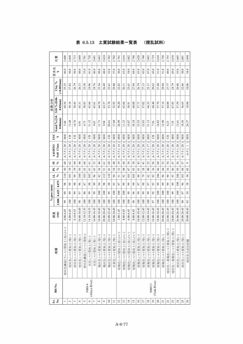
10) 土質試験結果 土質試験は、ボーリングによる不撹乱試料及び撹乱試料またテストピットによる試料に対して
実施した。これらの結果は、表 6.5.12 土質試験結果一覧表(不撹乱試料)、表 6.5.13 土質試験
結果一覧表 (撹乱試料)、表 6.5.14~表 6.5.16のテストピット試料土質試験結果一覧表に示す。 一覧表の記号は次の通りである。
LL(%) 液性限界 PL(%) 塑性限界 PI 塑性指数 SL(%) 収縮限界 OMC(%) 最適含水比 MDD(g/cm3) 最大乾燥密度 USCS 統一土質分類

A-6-76
表 6.5.12 土質試験結果一覧表(不撹乱試料)
C
,K
Paφ
e oe f
Cc
1暗
灰色
シル
ト質
粘土
2.00
-2.5
010
010
099
115
3877
A-7
-5(
20)
CH23
.10
59.5
117
.39
41.5
2.73
33.
231.
855
69-
-1.
0573
0.82
0.38
9
2黄
灰色
シル
ト質
粘土
5.40
-5.7
510
099
9710
240
62A
-7-5
(20
)CH
25.0
352
.92
22.0
534
.02.
717
-1.
397
--
--
--
3灰
色シ
ルト質
粘土
2.00
-2.5
010
099
9810
735
72A
-7-5
(20
)CH
13.7
367
.85
18.4
240
.02.
675
2.83
1.66
423
137
12°
--
-
4灰
色シ
ルト質
粘土
2.50
-300
100
9998
105
4065
A-7
-5(
20)
CH9.
8067
.78
22.4
238
.02.
630
-1.
764
--
-0.
8858
0.84
870.
11
5暗
灰色
シル
ト質
粘土
2.00
-2.5
098
9594
102
3270
A-7
-5(
20)
CH11
.49
66.1
820
.23
38.0
2.27
01.
871.
727
--
-1.
193
1.10
050.
07
6暗
灰色
シル
ト質
粘土
2.50
-3.0
010
010
098
116
4769
A-7
-5(
20)
CH21
.95
61.3
916
.66
45.0
2.73
64.
401.
613
-42
16°
--
-
7暗
灰色
シル
ト質
粘土
2.00
-250
100
100
9998
4751
A-7
-5(
20)
MH
12.0
865
.34
22.5
737
.82.
625
3.84
1.78
5-
--
0.97
640.
7284
0.48
28
暗灰
色シ
ルト質
粘土
2.50
-3.0
010
010
099
9937
62A
-7-5
(20
)CH
6.44
76.7
816
.77
34.7
2.71
57.
261.
635
-38
12°
--
-
9A
beya
R.( 右
岸)
NBH
5暗
灰色
シル
ト質
粘土
3.00
-3.5
010
010
099
9037
53A
-7-5
(20
)CH
29.1
448
.31
22.5
544
.02.
698
-1.
223
--
--
--
10台
地N
BH6
暗灰
色シ
ルト質
粘土
2.50
-300
100
9997
9644
52A
-7-5
(20
)M
H12
.44
64.4
623
.11
40.1
2.65
26.
171.
725
13-
-1.
0992
0.74
950.
575
11Bo
gena
R.( 左
岸)
NBH
7暗
灰色
礫混
じり
シル
ト質
粘土
3.00
-3.5
010
093
8780
3743
A-7
-5(
20)
MH
18.6
757
.91
22.9
431
.02.
865
-1.
463
--
--
--
12Bo
gena
R.( 右
岸)
NBH
8暗
灰色
シル
ト質
粘土
2.50
-3.0
010
099
9811
646
70A
-7-5
(20
)CH
25.5
253
.79
20.6
961
.02.
747
-1.
124
--
--
--
13赤
褐色
色シ
ルト質
粘土
2.00
-2.4
010
010
099
5231
21A
-7-5
(15
)M
H10
.45
63.6
325
.92
35.3
2.66
015
.06
1.67
1-
--
1.06
540.
958
0.21
614
赤褐
色色
シル
ト質
粘土
2.40
-2.8
010
010
099
6338
25A
-7-5
(18
)M
H24
.45
59.4
216
.13
31.0
2.76
0-
1.61
230
845
17°
--
-
15Y
eda
R.( 左
岸)
NBH
11暗
灰色
シル
ト質
粘土
2.50
-3.0
010
097
9694
3757
A-7
-5(
20)
CH18
.10
56.1
625
.74
42.3
2.62
76.
791.
782
4428
14°
--
-
16暗
灰色
シル
ト質
粘土
2.00
-2.5
010
010
010
080
4040
A-7
-5(
20)
MH
24.5
545
.27
30.1
843
.12.
712
7.75
1.72
735
--
0.90
70.
630.
233
17暗
灰色
シル
ト質
粘土
2.50
-3.0
010
010
099
8241
41A
-7-5
(20
)M
H11
.10
62.7
526
.15
43.5
2.60
9-
1.69
4-
3615
°-
--
18暗
褐色
シル
ト質
粘土
2.00
-2.5
010
098
9261
3427
A-7
-5(
19)
MH
18.5
552
.84
28.6
130
.52.
804
10.7
31.
685
104
--
0.90
70.
560.
258
19暗
褐色
シル
ト質
粘土
2.50
-3.0
010
010
099
6836
32A
-7-5
(20
)M
H31
.55
51.9
916
.46
49.3
2.72
8-
1.66
7-
127°
--
-
20Y
eda
R.N
BH13
-2
暗褐
色シ
ルト質
粘土
2.00
-2.5
010
097
9594
4054
A-7
-5(
20)
MH
12.4
963
.33
24.1
821
.32.
698
2.45
1.69
451
3810
°-
--
21Ch
emog
a R.
( 左岸
)N
BH16
明褐
色シ
ルト質
粘土
2.00
-2.5
010
097
9670
3931
A-7
-5(
20)
MH
32.4
540
.53
27.0
245
.02.
793
-1.
143
--
--
--
22Ch
emog
a R.
( 右岸
)N
BH17
暗灰
色砂
質粘
土2.
50-3
.00
9584
8377
3740
A-7
-5(
20)
MH
16.0
156
.95
22.0
835
.02.
836
-1.
410
--
--
--
23A
bahi
m R
.( 左岸
)N
BH18
暗褐
色シ
ルト質
粘土
5.00
-5.5
099
9795
5332
21A
-7-5
(15
)M
H14
.73
60.8
023
.51
45.0
2.65
2-
1.69
732
--
--
-
一軸
(K
Pa )
USC
S
沈降
分析
Sand
%(2
.0-
0.06
mm
)
Silt
%(0
.06-
0.02
mm
)
Cla
y%(<
0.00
2m
m)
Sr.
No
地層
圧密
試験
三軸
(UU
)
NBH
2
NBH
3
0.425
0.075
深度
(m)
単体
体積
重量
(γ
t)
(g/
cm
3)
AA
SHTO
土質
区分
含水
比
%比
重S.
L %
Ziba
R.( 右
岸)N
ear t
he
Yed
a R.
( 左岸
)N
BH12
NBH
13Y
eda
R.( 左
岸)
Nea
r the
rive
r
PI %B
H N
o.LL %
NBH
4
PL %
NBH
10
NBH
1
% p
ass
(mm
)
調査
地点
2.000
ブラ
ック
コッ
トン
ソイ
ル(台
地)
ブラ
ック
コッ
トン
ソイ
ル(台
地)
Aba
dem
R.( 右
岸)
Abe
ya R
.( 左岸
)
A-6-77
表 6.5.13 土質試験結果一覧表 (撹乱試料)
1暗
灰色
礫混
じり
シル
ト質
粘土
(柔ら
かい
)4.
00-4
.45
9999
9811
050
60A
-7-5
(20
)M
H5.
4468
.54
25.2
546
.02.
606
2暗
灰色
シル
ト質
粘土
(堅
い)
6.00
-6.4
510
099
9910
139
62A
-7-5
(20
)C
H13
.48
58.1
627
.82
50.0
2.66
0
3暗
灰色
シル
ト質
粘土
(堅
い)
8.10
-8.5
510
099
9899
3960
A-7
-5(
20)
CH
14.7
658
.45
26.7
950
.02.
715
4暗
灰色
シル
ト質
粘土
(堅
い)
10.0
0-10
.45
9897
9610
456
48A
-7-5
(20
)M
H6.
9165
.31
26.1
348
.02.
660
5暗
灰色
礫混
じり
シル
ト質
粘土
12.1
0-12
.55
100
8887
103
4360
A-7
-5(
20)
MH
6.71
58.8
325
.58
53.0
2.70
1
6灰
色シ
ルト質
粘土
(堅い
)14
.10-
14.5
510
099
9810
241
61A
-7-5
(20
)C
H11
.12
63.6
624
.96
41.0
2.72
8
7灰
色シ
ルト質
粘土
(堅い
)16
.00-
16.4
510
099
9996
4353
A-7
-5(
20)
MH
9.63
65.6
124
.76
46.0
2.64
1
8褐
灰色
シル
ト質
粘土
(堅
い)
18.0
0-18
.45
100
100
9482
3646
A-7
-5(
20)
MH
11.7
164
.74
23.5
449
.02.
665
9褐
灰色
シル
ト質
粘土
(堅
い)
20.0
0-20
.45
100
100
9811
251
61A
-7-5
(20
)M
H9.
9463
.57
26.4
948
.02.
624
10褐
灰色
シル
ト質
粘土
(堅
い)
22.0
0-22
.45
100
9998
110
4169
A-7
-5(
20)
CH
20.6
153
.78
25.6
152
.02.
702
11灰
黄色
シル
ト質
粘土
(堅
い)
24.0
0-24
.45
100
100
9394
5440
A-7
-5(
20)
MH
17.6
852
.92
29.4
057
.02.
702
12暗
褐色
シル
ト質
粘土
(柔
らか
い)
1.00
-1.4
510
010
097
5132
19A
-7-5
(14
)M
H26
.99
50.2
022
.82
30.0
2.74
1
13暗
褐色
シル
ト質
粘土
(柔
らか
い)
4.00
-4.4
510
010
099
9248
44A
-7-5
(20
)M
H11
.23
62.6
626
.11
63.0
2.61
6
14暗
褐色
シル
ト質
粘土
(柔
らか
い)
6.00
-6.4
510
099
9910
147
54A
-7-5
(20
)M
H15
.07
58.9
125
.61
54.0
2.68
2
15暗
褐色
シル
ト質
粘土
(柔
らか
い)
8.00
-8.4
598
9694
103
4558
A-7
-5(
20)
MH
10.1
860
.08
27.9
469
.02.
740
16暗
褐色
シル
ト質
粘土
(堅
い)
10.0
0-10
.45
100
9997
8441
43A
-7-5
(20
)M
H15
.55
57.7
126
.74
43.0
2.62
8
17暗
褐色
シル
ト質
粘土
(堅
い)
12.0
0-12
.45
100
9998
7938
41A
-7-5
(20
)M
H15
.83
57.0
227
.15
45.0
2.74
0
18暗
褐色
シル
ト質
粘土
(堅
い)
14.0
0-14
.45
100
9997
6240
22A
-7-5
(17
)M
H11
.13
66.3
322
.11
47.0
2.60
3
19暗
褐色
シル
ト質
粘土
(堅
い)
16.0
0-16
.45
9795
9392
3656
A-7
-5(
20)
CH
7.56
68.4
020
.63
45.0
2.71
9
20暗
褐色
シル
ト質
粘土
(堅
い)
18.0
0-18
.45
100
100
9910
646
60A
-7-5
(20
)M
H14
.82
57.7
027
.48
51.0
2.61
0
21暗
褐色
シル
ト質
粘土
(堅
い)
20.0
0-20
.45
100
100
9996
4452
A-7
-5(
20)
MH
12.9
057
.16
29.9
451
.02.
728
22暗
灰色
~黄
褐色
シル
ト質
粘土
(堅
い)
22.0
0-22
.45
100
100
9990
3654
A-7
-5(
20)
CH
8.23
64.0
027
.77
49.0
2.75
5
23暗
灰色
~黄
褐色
シル
ト質
粘土
(堅
い)
24.0
0-24
.45
100
9999
9346
47A
-7-5
(20
)M
H7.
3567
.85
24.7
945
.02.
618
24暗
灰色
シル
ト質
粘土
(堅
い)
26.0
0-26
.45
100
100
100
106
5056
A-7
-5(
20)
MH
13.6
157
.59
28.8
055
.02.
605
25暗
灰色
シル
ト質
粘土
(堅
い)
28.0
0-28
.45
9897
9610
144
57A
-7-5
(20
)M
H18
.56
56.6
522
.66
30.0
2.60
1
26暗
灰色
玄武
岩砂
礫30
.00-
30.4
563
5438
5445
9A
-5(
1)
MH
26.3
718
.06
18.0
634
.02.
694
US
C SPL %
PI %S
ilt %
(0.0
6-0.
02m
m)
Cla
y %
(<0.
002m
m)
LL %含
水比
%
沈降
分析
San
d %
(2.0
-0.
06m
m)
深度
(cm
)
% p
ass
(mm
)B
H N
o.比
重2.
000
0.42
5
NB
H13
(Yed
a R
iver
)
NB
H-4
(Abe
ya R
iver
)
AA
SH
TO
Soi
l C
lass
Sr. No
地層
0.07
5
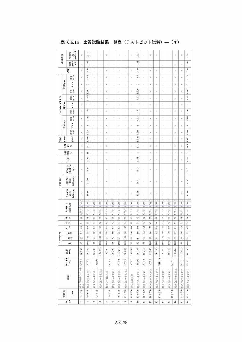
A-6-78
表 6.5.14 土質試験結果一覧表(テストピット試料)―(1)
MD
D
距離
程T-
180
(km
)g/
cm3
密度
g/cm
3C
BR
膨張
率 %
密度
g/cm
3C
BR
膨張
率 %
密度
g/cm
3C
BR
膨張
率 %
密度
gm/c
m3
乾燥
密
度gm
/cm
3
11
+ 50
0暗
灰色
礫混
じり
シル
ト
質粘
土N
TP
180
-200
6562
5569
3138
A-7
-5(
14)
--
--
--
--
--
--
--
--
--
-
24
+ 00
0暗
灰色
シル
ト質
粘土
NT
P 2
60-2
4010
010
098
8938
51A
-7-5
(20
)10
.10
61.3
028
.60
2.60
311
24.0
1.49
01.
220
111
.43
1.38
71
11.0
41.
501
29.
9638
.01.
763
1.27
8
3暗
灰色
シル
ト質
粘土
45-3
0098
9488
8741
46A
-7-5
(20
)-
--
--
--
--
--
--
--
--
--
4暗
灰色
シル
ト質
粘土
190-
270
100
100
9810
936
73A
-7-5
(20
)-
--
--
--
--
--
--
--
--
--
5褐
色シ
ルト質
粘土
0-70
100
9994
8343
40A
-7-5
(20
)-
--
--
--
--
--
--
--
--
--
6暗
灰色
シル
ト質
粘土
70-3
0096
8380
8743
44A
-7-5
(20
)-
--
--
--
--
--
--
--
--
--
79
+ 50
0暗
灰色
シル
ト質
粘土
NT
P 5
110-
240
100
9795
8541
44A
-7-5
(20
)-
--
--
--
--
--
--
--
--
--
811
+ 5
00暗
灰色
シル
ト質
粘土
NT
P 6
50-2
5010
010
098
117
4473
A-7
-5(
20)
--
--
--
--
--
--
--
--
--
-
913
+ 5
00風
化玄
武岩
礫N
TP
713
5-20
067
5446
8038
42A
-7-5
(10
)-
--
--
--
--
--
--
--
--
--
1013
+ 5
00暗
灰色
シル
ト質
粘土
NT
P770
-135
9288
8680
3842
A-7
-5(
20)
13.5
059
.41
19.3
92.
651
817
.01.
510
1.26
61
9.13
1.45
01
8.60
1.52
62
7.95
38.0
1.83
11.
327
1115
+ 5
00暗
灰色
シル
ト質
粘土
NT
P 8
55-2
1098
9592
105
4362
A-7
-5(
20)
--
--
--
--
--
--
--
--
--
-
1216
+ 5
00暗
灰色
シル
ト質
粘土
NT
P 9
85-2
4010
098
9612
249
73A
-7-5
(20
)-
--
--
--
--
--
--
--
--
--
13暗
灰色
シル
ト質
粘土
60-1
3010
098
9598
4454
A-7
-5(
20)
--
--
--
--
--
--
--
--
--
-
14暗
灰色
シル
ト質
粘土
130-
240
100
100
9912
147
74A
-7-5
(20
)-
--
--
--
--
--
--
--
--
--
15暗
灰色
シル
ト質
粘土
50-1
3010
098
9089
4247
A-7
-5(
20)
--
--
--
--
--
--
--
--
--
-
16暗
灰色
シル
ト質
粘土
130-
140
100
9992
8153
28A
-7-5
(19
)-
--
--
--
--
--
--
--
--
--
1721
+ 5
00暗
灰色
シル
ト質
粘土
NT
P12
110-
210
9998
9610
453
51A
-7-5
(20
)-
--
--
--
--
--
--
--
--
--
1823
+ 0
00暗
灰色
シル
ト質
粘土
NT
P13
55-3
0010
097
9486
3551
A-7
-5(
20)
11.1
061
.54
27.3
62.
784
626
.51.
561
1.16
61
8.80
1.39
72
8.66
1.49
72
8.38
33.0
1.70
71.
283
比重
収縮
限界 %
沈降
分析
Sand
%(2
.0-
0.06
mm
)
Silt
%(0
.06-
0.02
mm
)
Cla
y%(<
0.00
2mm
)
NM
C
% p
ass
(mm
)
LL %
2.000
0.425
OM C %
3 - P
oint
CB
R %
10
blow
s30
blo
ws
65 b
low
sSr
.N
o
5 +
500
NT
P3
NT
P 10
7 +
500
NT
P 4
17 +
500
AA
SHTO
土質
区分
0.075
地層
深度
(cm
)Te
st P
itN
o.PL %
PI %
NT
P11
19 +
500
現場
密度

A-6-79
表 6.5.15 土質試験結果一覧表(テストピット試料)―(2)
MD
D
距離
程T-
180
(km
)g/
cm3
密度
g/cm
3C
BR
膨張
率 %
密度
g/cm
3C
BR
膨張
率 %
密度
g/cm
3C
BR
膨張
率 %
密度
gm/c
m3
乾燥
密
度gm
/cm
3
19褐
色~
暗褐
色シ
ルト
質粘
土50
-160
9792
8374
4034
A-7
-5(
20)
--
--
--
--
--
--
--
--
--
-
20暗
灰色
シル
ト質
粘土
160-
250
9683
8095
3857
A-7
-5(
20)
--
--
--
--
--
--
--
--
--
-
2126
+ 5
00暗
灰色
シル
ト質
粘土
NT
P15
75-3
0094
9189
8643
43A
-7-5
(20
)17
.72
58.0
818
.50
2.64
59
20.0
1.53
01.
238
113
.34
1.42
32
13.2
01.
522
212
.37
53.0
1.74
71.
142
2227
+ 5
00暗
灰色
シル
ト質
粘土
NT
P 16
70-2
7097
9287
112
4171
A-7
-5(
20)
--
--
--
--
--
--
--
--
--
-
23暗
灰色
シル
ト質
粘土
50-2
5097
9287
7538
37A
-7-5
(20
)-
--
--
--
--
--
--
--
--
--
24暗
灰色
シル
ト質
粘土
250-
300
100
9795
102
3963
A-7
-5(
20)
--
--
--
--
--
--
--
--
--
-
2530
+ 0
00暗
灰色
シル
ト質
粘土
NT
P 18
110-
300
100
100
9910
243
59A
-7-5
(20
)-
--
--
--
--
--
--
--
--
--
2632
+ 0
00赤
褐色
シル
ト質
粘土
NT
P19
0-25
010
010
098
7936
43A
-7-5
(20
)23
.65
48.3
528
.00
2.75
914
26.3
1.45
01.
106
14.
041.
347
32.
781.
429
90.
9935
.01.
737
1.20
7
2734
+ 5
00暗
褐色
シル
ト質
粘土
NT
P 20
0-30
010
099
9788
4246
A-7
-5(
20)
--
--
--
--
--
--
--
--
--
-
28暗
灰色
シル
ト質
粘土
0-13
010
094
9187
4146
A-7
-5(
20)
--
--
--
--
--
--
--
--
--
-
29明
褐色
シル
ト質
粘土
130-
250
9283
7789
3950
A-7
-5(
20)
--
--
--
--
--
--
--
--
--
-
30暗
灰色
シル
ト質
粘土
0-14
098
9491
9341
52A
-7-5
(20
)-
--
--
--
--
--
--
--
--
--
31明
褐色
シル
ト質
粘土
と玄
武岩
礫14
0-27
088
8279
9036
54A
-7-5
(20
)-
--
--
--
--
--
--
--
--
--
3238
+ 5
00暗
灰色
シル
ト質
粘土
NT
P 23
50-2
7097
9392
7846
32A
-7-5
(20
)-
--
--
--
--
--
--
--
--
--
3340
+ 5
00赤
褐色
シル
ト質
粘土
NT
P 24
0-22
010
099
9763
3726
A-7
-5(
18)
--
--
--
--
--
--
--
--
--
-
3442
+ 5
00赤
褐色
シル
ト質
粘土
NT
P25
70-3
0010
099
9762
3428
A-7
-5(
20)
11.0
062
.38
26.1
72.
732
1721
.71.
483
1.11
41
3.24
1.37
34
2.59
1.47
39
1.15
31.0
1.58
91.
213
3543
+ 5
00玄
武岩
礫N
TP
260-
150
9594
9062
3725
A-7
-5(
18)
--
--
--
--
--
--
--
--
--
-
3645
+ 0
00明
褐色
シル
ト質
粘土
NT
P 27
50-2
5010
010
097
6339
24A
-7-5
(18
)-
--
--
--
--
--
--
--
--
--
3746
+ 5
00暗
褐色
シル
ト質
粘土
NT
P 28
60-2
5099
9691
8444
40A
-7-5
(20
)-
--
--
--
--
--
--
--
--
--
3848
+ 0
00暗
灰色
シル
ト質
粘土
NT
P 29
0-30
098
9594
106
4858
A-7
-5(
20)
--
--
--
--
--
--
--
--
--
-
3949
+ 5
00暗
灰色
~暗
褐色
沖積
粘土
NT
P30
0-24
010
099
9810
057
43A
-7-5
(20
)9.
8061
.58
28.6
22.
783
1429
.01.
385
1.12
62
9.88
1.32
42
8.39
1.39
32
7.85
36.0
1.54
61.
137
Silt
%(0
.06-
0.02
mm
)
Cla
y%(<
0.00
2mm
)
沈降
分析
Sand
%(2
.0-
0.06
mm
)
Sr.
No
地層
Test
Pit
No.
36 +
000
深度
(cm
)
% p
ass
(mm
)
PL %
0.425
0.075
2.000
24 +
000
NT
P14
29 +
000
NT
P17
37 +
500
NT
P 22
NT
P 21
30 b
low
s65
blo
ws
10
blow
sPI %
AA
SHTO
土質
区分
LL %
現場
密度
NM
C比
重
収縮
限界 %
3 - P
oint
CB
R %
OM C %
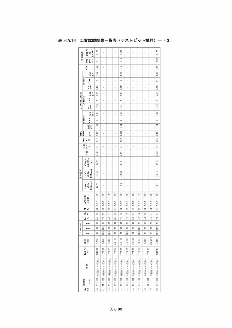
A-6-80
表 6.5.16 土質試験結果一覧表(テストピット試料)―(3)
MD
D
距離
程T-
180
(km
)g/
cm3
密度
g/cm
3C
BR
膨張
率 %
密度
g/cm
3C
BR
膨張
率 %
密度
g/cm
3C
BR
膨張
率 %
密度
gm/c
m3
乾燥
密
度gm
/cm
3
4050
+ 5
00暗
灰色
シル
ト質
粘土
NT
P31
0-27
099
9490
8642
44A
-7-5
(20
)16
.35
56.5
526
.23
2.80
213
24.0
1.46
31.
159
18.
851.
370
27.
331.
474
26.
3946
.01.
711
1.17
2
4151
+ 5
00明
褐色
シル
ト質
粘土
NT
P 32
0-24
010
010
098
7033
37A
-7-5
(20
)-
--
--
--
--
--
--
--
--
--
4253
+ 0
00明
褐色
シル
ト質
粘土
NT
P 33
0-18
010
097
9363
4122
A-7
-5(
17)
--
--
--
--
--
--
--
--
--
-
4355
+ 0
00赤
褐色
シル
ト質
粘土
NT
P 34
60-1
0097
9694
8143
38A
-7-5
(20
)-
--
--
--
--
--
--
--
--
--
4456
+ 5
00明
褐色
シル
ト質
粘土
NT
P 35
80-1
8097
8785
7645
31A
-7-5
(20
)19
.453
.89
24.0
12.
771
1423
.51.
542
1.23
42
6.55
1.45
33
5.34
1.52
74
3.79
41.0
1.91
01.
355
4557
+ 5
00赤
褐色
シル
ト質
粘土
NT
P 36
45-2
0010
099
9871
3932
A-7
-5(
20)
--
--
--
--
--
--
--
--
--
-
4659
+ 0
00赤
褐色
シル
ト質
粘土
NT
P 37
50-3
0092
9089
8044
36A
-7-5
(20
)-
--
--
--
--
--
--
--
--
--
4760
+ 5
00赤
褐色
シル
ト質
粘土
NT
P 38
40-2
5010
010
095
5936
23A
-7-5
(17
)-
--
--
--
--
--
--
--
--
--
48赤
褐色
シル
ト質
粘土
0-18
098
9389
6433
31A
-7-5
(20
)-
--
--
--
--
--
--
--
--
--
49赤
褐色
シル
ト質
粘土
180-
280
9897
9565
3431
A-7
-5(
20)
--
--
--
--
--
--
--
--
--
-
5063
+ 0
00赤
褐色
シル
ト質
粘土
NT
P40
0-26
010
010
098
7444
30A
-7-5
(20
)10
.160
.16
29.4
42.
753
1727
.01.
464
1.15
42
3.86
1.34
26
2.84
1.38
311
2.07
43.0
1.68
21.
176
PL %LL %
AA
SHTO
土質
区分
PI %
62 +
000
NT
P 39
% p
ass
(mm
)
2.000
3 - P
oint
CB
R %
30 b
low
s沈
降分
析
Sand
%(2
.0-
0.06
mm
)
Silt
%(0
.06-
0.02
mm
)
Cla
y%(<
0.00
2mm
)
Sr.
No
地層
Test
Pit
No.
深度
(cm
)
0.425
0.075
現場
密度
NM
C比
重
収縮
限界 %
OM C %
65 b
low
s 1
0 bl
ows

A-6-81
収縮試験 収縮試験から求められる収縮限界は、土が塑性状態から固体状態に変化するときの含水比であり、
土の基本的な物理的指標の一つである。試験結果によれば、収縮限界(SL)と収縮比(R)は、次
の通りである。
表 6.5.17 収縮限界と収縮比 地層 SL(%) R 平均 SL(%) 平均 R ブラックコットンソイル 3.2~12.5 2.0~2.2 6.7 2.1 赤色土 14.1~16.8 1.9~2.0 15.7 1.9
平均収縮限界はブラックコットンソイルと赤色土では 2 倍以上の差が認められる。これはブラッ
クコットンソイルが粘土質で間隙比が大きく、赤色土がシルト質で間隙比が小さいことによるもの
である。次に収縮限界を利用して土の膨潤度(Expansiveness)を求めることができる。 エチオピア ERA 野外調査マニュアル(2002)及びタンザニア道路設計マニュアル(1999)によ
れば膨潤度は、次式によって求められる。 Εex = 2.4Wp-3.9Ws+32.5
Εex = 膨潤度(Expansiveness) W p(%)= PI (0.425mm フルイを通過した試料の塑性指数)/100 Ws(%)= SL (0.425mm フルイを通過した試料の収縮限界)/100
これらの指標値は上記マニュアルによって、次のように区分され、地層の良否の判定に利用され
ている。
表 6.5.18 膨潤度の判定区分
膨潤度 程度 <20 低位
20-50 中位 >50 高位
次に調査結果に基く膨潤度(Εex)の計算結果を次表に示す。
表 6.5.19 膨潤度の計算結果
Km 地層 通過% 0.425mm LL(%) PL(%) PI(%) SL(%)
Wp(%) Ws(%) Eex
4+000 BCS 99 89 38 51 11 50.5 10.9 111 13+500 BCS 92 80 38 42 8 38.6 7.4 97 23+000 BCS 96 86 35 51 6 49.0 5.8 128 26+500 BCS 85 86 43 43 9 36.6 7.7 90 32+000 赤色シルト 100 79 36 43 14 43.0 14.0 81 42+500 赤色シルト 99 62 34 28 17 27.7 16.8 33 49+500 褐色粘土 100 100 57 43 14 43.0 14.0 81 50+500 BCS 95 86 42 44 13 41.8 12.4 85 56+500 褐色粘土 86 76 45 31 14 26.7 12.0 50 63+000 赤色シルト 99 74 44 30 17 29.7 16.8 38
上表の結果によれば、すべてのブラックコットンソイルは膨潤度 85 以上を示し、著しく膨潤度
は高い。一方、赤色土(シルト)の膨潤度は、33~81 を示し、ブラックコットンソイルに比較す
ると低いものの、中位~高位に区分される。

A-6-82
一軸圧縮試験 一軸圧縮試験は、次の 9 試料で実施した。結果は次の通りである。
表 6.5.20 一軸圧縮試験結果 BH No. 地層名 一軸圧縮強度( KPa ) NBH 1 ブラックコットンソイル(BCS) 69 NBH 2 下位粘土(LC) 231 NBH 6 ブラックコットンソイル(BCS) 13
NBH 10 赤色シルト(URC) 308 NBH 11 ブラックコットンソイル(BCS) 44 NBH 12 ブラックコットンソイル(BCS) 35 NBH 13 褐色粘土(UBC) 104
NBH 13-2 褐色粘土(UBC) 51 NBH18 褐色粘土(UBC) 32
上表のうち、NBH 2 の下位粘土(LC)と NBH10 の赤色シルト(URC)が著しく高い値を示す。
この 2 試料はいずれも N 値 10~15 を示す硬質シルト~粘土である。ブラックコットンソイルの一
軸圧縮強度は、13~69KPa の範囲にある。
三軸圧縮試験(UU) 三軸圧縮試験(UU)は、次の 8 試料で実施した。結果は次の通りである。
表 6.5.21 三軸圧縮試験結果
BH No. 地層名 粘着力 C (KPa)
内部摩擦角Φ
(°) NBH 2 ブラックコットンソイル(BCS) 37 12 NBH 3 ブラックコットンソイル(BCS) 42 16 NBH 4 ブラックコットンソイル(BCS) 38 12
NBH 10 赤色粘土(URC) 45 17 NBH 11 ブラックコットンソイル(BCS) 28 14 NBH 12 ブラックコットンソイル(BCS) 36 15 NBH 13 褐色粘土(UBC) 12 7
NBH 13-2 褐色粘土(UBC) 38 10
上表のうち NBH10 の赤色シルト(URC)は、粘着力、内部摩擦角とも最大値を示す・
圧密試験 圧密沈下の検討は、台地上のデジェン側のブラックコットンソイル分布区間、アベヤ川、イエダ
川の谷底平野の計 3 地点を代表地点として実施した。計算は⊿e 法により次の 4 ケースで実施した。
表 6.5.22 圧密試験結果 ケース 1 デジェン(NBH2)
盛土高=1m 盛土γt=19.0 KN/m2 e 0=0.8858 上面幅=11m 沈下層γt=17.6 KN/m2 e f=0.8487 底面幅=15m 沈下層の厚さ=5.0m Cc=0.07 法勾配=1:2 地下水位=なし
表 6.5.23 圧密試験結果 ケース 2 デジェン(NBH2)
盛土高=3m 盛土γt=19.0 KN/m2 e 0=0.8858

A-6-83
上面幅=11m 沈下層γt=17.6 KN/m2 e f=0.7284 底面幅=23m 沈下層の厚さ=5.0m Cc=0.07 法勾配=1:2 地下水位=なし
表 6.5.24 圧密試験結果 ケース 3 アベヤ(NBH4)
盛土高=5m 盛土γt=19.0 KN/m2 e 0=0.9764 上面幅=11m 沈下層γt=17.9KN/m2 e f=0.7284 底面幅=31m 沈下層の厚さ=10.0m Cc=0.482 法勾配=1:2 地下水位=-1.0m
表 6.5.25 圧密試験結果 ケース 4 イエダ(NBH13)
盛土高=5m 盛土γt=19.0 KN/m2 e 0=0.907 上面幅=11m 沈下層γt=16.9KN/m2 e f=0.560 底面幅=31m 沈下層の厚さ=10.0m Cc=0.258 法勾配=1:2 地下水位=-1.2m
解析結果は次の通りである。
表 6.5.26 圧密解析結果
地点名 デジェン
(NBH2) デジェン
(NBH2) アベヤ
(NBH4) イエダ
(NBH13) 盛土高 H =1m H =3m H =5m H =5m
最終沈下量 0.028cm 0.067cm 4.2cm 25.1cm 圧密沈下度 90%に達する時間 490 ヶ月 494 ヶ月 903 ヶ月 119 ヶ月
沈下量は、イエダ川が最大を示す。これは、イエダ川がアベヤ川に比べて氾濫回数、時間共に多
く、軟弱な粘土が堆積しているためと推定される。沈下時間は CV 値が小さく、いずれも長時間を
示す。
CBR 試験 CBR 試験は、40 ヶ所のテストピットのうち 10 ヶ所から採取した試料に対し実施した。 結果
は次の通りである。
表 6.5.27 CBR 試験結果
TP No. 地層 最適含水比OMC (%)
最大乾燥密度MDD(g/cm3)
CBR (65blows)
膨張比Swell(%)
NTP2 ブラックコットンソイル 24.0 1.490 2 9.96 NTP7 ブラックコットンソイル 17.0 1.510 2 7.95
NTP13 ブラックコットンソイル 26.5 1.561 2 8.38 NTP15 ブラックコットンソイル 20.0 1.530 2 12.37 NTP19 赤色シルト 26.3 1.450 9 0.99 NTP25 赤色シルト 21.7 1.483 9 1.15 NTP30 褐色粘土 29.0 1.385 2 7.85 NTP31 ブラックコットンソイル 24.0 1.463 2 6.39 NTP35 赤色シルト 23.5 1.542 4 3.79 NTP40 赤色シルト 27.0 1.464 11 2.07
上表によれば、ブラックコットンソイルの CBR 値はすべて 2 を示す。これに対し、赤色粘土の
CBR値は 4~11であり、明瞭な強度の違いが認められる。またCBR試験に伴う吸水膨張試験(Swell)

A-6-84
は、突き固めた試料に対して水浸後の体積変化を見るものであるが、ブラックコットンソイルが
6.39~12.37(%)と高い値を示すのに対し、赤色粘土は 0.99~3.79 と著しく低い値を示す。 日本の土質工学会基準によれば膨張比については次のような区分がある。
表 6.5.28 膨張比区分
路床の状態 膨張比(%) 良好な路床 1 以下 通常な路床 3 以下 不良な路床 3 以上 腐植土 7~20
これによれば、ブラックコットンソイルはすべて 3 以上の不良な路床に区分される。
岩石試験 岩石試験は、次の 3 試料について実施した。結果は次の通りである。
表 6.5.29 岩石試験結果
BH No. 岩石 層相 圧縮強度(MPa) NBH 4 玄武岩 強風化礫状コア 7 NBH 7 玄武岩 新鮮な棒状コア 25 NBH12 玄武岩 変質した棒状コア 12
上記の結果は、玄武岩の風化過程における強度変化を明瞭に示している。 一般
に、岩盤は風化程度に応じて A~D 級岩盤まで区分される。
表 6.5.30 岩盤区分
岩質区分 A B C D 圧縮強度(MPa) 120 以上 25~120 18.5 8
この区分に従えば NBH4 は D 級、NBH7 は B 級、NBH12 は C 級岩盤に区分される。但し、これ
らの岩盤は、N 値 50 以上を示しており、支持層として問題はない
11) ブラックコットンソイルの施工上の問題点 ブラックコットンソイルの特徴は一般的な粘性土に比較して著しく膨潤度(Expansiveness)が高
いことである。膨潤は、乾季と雨季の繰り返しによる含水量の変化によって発生する。即ち、雨季
には含水量の増加に伴い膨潤が発生し、乾季には含水量の減少と共に収縮が発生する。この繰り返
しが地盤に変状をもたらす結果となる。乾季と雨季の含水量の違いを比較するには、それぞれの季
節における同一の地形条件、同一地質条件、同一深度での比較が必要である。そこで、2003 年 11月(乾季)と 2010 年 9 月(雨季)における同じ平坦な台地面で直接ブラックコットンソイルが地
表に露出している地点の含水量を比較すると次の通りである。
表 6.5.31 雨季(2010 年 9 月)ブラックコットンソイル含水量
ボーリング 深度(m) 含水量(%) NBH 1 2.0~2.5 41.5 BNH 2 2.0~2.5 38.0

A-6-85
表 6.5.32 乾季(2003 年 11 月)ブラックコットンソイル含水量
ボーリング 深度(m) 含水量(%) BH 1 2.0~3.0 31.0
両者を比較すると、雨季は乾季に比較して約 7~10%程度含水量が増加する。この含水量の変化
を収縮試験結果と比較した結果を 表 6.5.33に示す。線収縮は収縮試験による体積変化を立方体 1辺の長さの変化に換算したものである。これによれば、ブラックコットンソイルは含水比が 10%増加すると線収縮は 2~6%(平均 3.6%)増加する。逆に含水比が 10%減少すれば線収縮は同じ割
合で減少する。即ち、ブラックコットンソイルを 1m3 の立方体と仮定すると 1 辺 1m当たり、平
均 3.6%の割合で増減が発生することとなる。但し、一般に季節変化に伴う含水量の変化が発生す
るのは、凍結の起こる寒冷地を除き、地表よりおよそ数m程度と言われている。とは言え、膨潤、
収縮の繰り返しは地表面の変形を引き起こす。この問題を解決するには、ブラックコットンソイル
の一部を膨潤性の低い良質土で置き換えるか又は、ライム(消石灰)などを混入する地盤改良が必
要となる。さらに、地盤の変状を引き起こすのは含水量の変化であることから、路床への水の浸入
を防ぐため路床、法尻などにおける十分な排水対策が必要とされる。
表 6.5.33 自然含水比と線収縮の関係
C(%) Ls(%) C(%) Ls(%) Rise(%) C(%) Ls(%) Rise(%) C(%) Ls(%) Rise(%)
NTP2 4+000 0.6-2.4 ブラックコットンソイル 38.0 11.2 2.1 56.3 14.0 77.3 18.0 4.0 98.3 21.0 7.0 119.3 23.0 9.0
NBH1 5+060 2.0-2.5 ブラックコットンソイル 41.5 3.2 2.1 80.7 18.0 101.9 21.0 3.0 123.0 23.0 5.0 144.0 26.0 8.0
NTP7 13+500 0.7-1.4 上位褐色粘土 38.0 8.1 2.3 68.8 16.0 91.8 20.0 4.0 114.8 22.0 6.0 137.8 25.0 9.0
NBH2 14+560 2.0-2.5 ブラックコットンソイル 40.0 2.8 2.2 81.8 18.0 103.8 22.0 4.0 125.8 24.0 6.0 147.8 26.0 8.0
NBH3 20+080 2.0-2.5 ブラックコットンソイル 38.0 1.9 2.2 61.8 15.0 101.4 21.0 6.0 123.4 23.0 8.0 145.4 26.0 11.0
3.0-3.5 ブラックコットンソイル 45.0 4.4 2.1 85.3 19.0 106.3 22.0 3.0 127.3 24.0 5.0 148.3 26.0 7.0
NBH4 22+040 2.0-2.5 ブラックコットンソイル 37.8 3.8 2.1 71.4 17.0 92.4 20.0 3.0 113.4 22.0 5.0 134.4 25.0 8.0
2.5-3.0 ブラックコットンソイル 34.7 7.3 2.1 57.5 14.0 78.5 18.0 4.0 99.5 21.0 7.0 120.5 23.0 9.0
NTP13 23+000 0.5-3.0 ブラックコットンソイル 33.0 5.7 2.3 62.8 15.0 85.8 19.0 4.0 108.8 22.0 7.0 131.8 25.0 10.0
NTP15 26+320 0.7-3.0 ブラックコットンソイル 53.0 9.2 2.1 92.0 20.0 113.0 22.0 2.0 134.0 25.0 5.0 155.0 27.0 7.0
NBH6 26+500 2.5-3.0 ブラックコットンソイル 40.1 6.2 2.0 67.8 16.0 87.8 19.0 3.0 107.8 22.0 6.0 127.8 24.0 8.0
NTP19 32+000 0.0-2.5 上位赤色粘土 35.0 15.1 1.9 37.8 10.0 56.8 14.0 4.0 75.8 17.0 7.0 94.8 20.0 10.0
NTP25 42+500 0.7-3.0 上位赤色粘土 31.0 16.8 1.9 27.0 8.0 46.0 12.0 4.0 65.0 15.0 7.0 84.0 19.0 11.0
NBH10 44+060 2.0-2.4 上位赤色粘土 35.3 15.1 1.9 37.4 10.0 57.4 14.0 4.0 76.4 17.0 7.0 95.4 20.0 10.0
NBH11 47+420 2.5-3.0 ブラックコットンソイル 42.3 6.8 2.1 74.6 17.0 95.6 20.0 3.0 116.6 23.0 6.0 137.6 25.0 8.0
NBH12 48+900 2.0-2.5 ブラックコットンソイル 43.1 7.8 2.0 70.6 16.0 90.6 20.0 4.0 110.6 23.0 7.0 130.6 25.0 9.0
NBH13 49+200 2.0-2.5 ブラックコットンソイル 30.5 10.7 2.0 39.6 10.0 59.6 14.0 4.0 79.6 18.0 8.0 99.6 21.0 11.0
NTP30 49+500 0.0-2.4 上位褐色粘土 36.0 14.1 1.9 41.6 11.0 60.6 15.0 4.0 79.6 18.0 7.0 98.6 21.0 10.0
NBH13-2 50+200 2.0-2.5 上位赤色粘土 21.3 2.5 2.1 41.6 11.0 60.6 15.0 4.0 79.6 18.0 7.0 98.6 21.0 10.0
NTP31 50+500 0.0-2.7 ブラックコットンソイル 46.0 12.5 2.1 30.4 16.0 91.4 20.0 4.0 112.4 22.0 6.0 133.4 25.0 9.0
NTP35 56+500 0.8-2.3 上位赤色粘土 41.0 14.4 2.0 53.2 13.0 73.2 17.0 4.0 93.2 20.0 7.0 113.2 22.0 9.0
NTP40 63+000 0.0-2.6 上位赤色粘土 43.0 18.3 1.9 46.9 12.0 65.9 16.0 4.0 84.9 19.0 7.0 103.9 21.0 9.0
NMC=自然含水比、SL=収縮限界、R=収縮比、C=体積変化、LS=線収縮、Rise=増加率
深度(m)NMC+20%NMC+10%NMC
地層 NMC(%) SL(%) RNMC+30%
No. Sta. (Km)
12) 材料調査 材料調査は、採石場(コンクリート用骨材)、土取場(盛土材料)に分けて調査を実施した。表 6.5.34、
表 6.5.35にテジェン~テブレマルコス間に位置する既設及び未開発の採石場及び土取場の一覧表
を示す。新たな採石場と土取場は、耕作地、放牧地を除き、車によるアクセス可能な未開発地を選
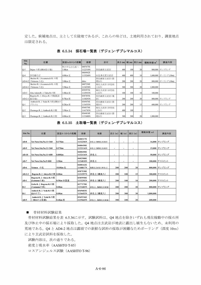
A-6-86
定した。候補地点は、主として丘陵地であるが、これらの殆どは、土地利用されており、調査地点
は限定される。
表 6.5.34 採石場一覧表(デジェン-デブレマルコス)
SiteNo. 位置 国道A-3からの距離 座標 岩石 長さ (m) 幅 (m) 高さ (m) 概略体積 m3 調査内容
Q-5 Dejen の南 (ERA採石場)町の中心から南へ1.0Km
0407675E1122318N 黒色緻密玄武岩 400 100 20 800,000 サンプリング
Q-4 23号線そば 4.0Km 北0404942E1135268N 灰色多孔質玄武岩 400 400 10 1,600,000 ボーリング (10m)
AD-4-2 Bechet R. とAsametech R. の間
(Yetnora の北) 3.0Km 北 ditto黒色緻密玄武岩(節理あり) 200 200 20 800,000 ボーリング (10m)
AD-4-1 Bechet R. とAsametech R. の間
(Yetnora の北) 3.5Km 北0407230E1134558N
風化玄武岩(赤色粘土あり) 300 300 20 1,800,000
AD-3 Aba Adem R. と Taba R.の間 1.0Km 南0392975E1129553N
風化玄武岩(赤色粘土あり) 100 100 10 100,000
AD-2-1Bogena R. と Abeya R. の間(既設
採石場) 0.7Km 南0387855E1130293N
黒色緻密玄武岩(塊状) 200 200 20 800,000 サンプリング
Q-1 Ambesh R. と Yeda R.の間 (ERAの
プラント) 0.2Km 南0369476E1136555N
黒色緻密玄武岩(節理あり) 200 200 15 600,000 サンプリング
Q-2 Chemoga R. と Ambesh R.の間 3.5Km 北0368376E1141783N
風化玄武岩(赤色粘土あり) 400 100 - -
Q-3 Chemoga R. と Ambesh R.の間 4.0Km 南0364818E1133488N
黒色緻密玄武岩(節理あり) 300 300 20 1,800,000
表 6.5.35 土取場一覧表(デジェン-デブレマルコス)
Site No. 位置 国道A-3からの距離 座標 地層 長さ (m) 幅 (m) 高さ (m)概略体積 m3
調査内容
AD-8 Yet Nora Sta.No.11+360 0.37Km0400317E1132256N 赤色土(強風化玄武岩) - - - 16,000 サンプリング
AD-9 Yet Nora Sta.No.11+360 0.57Km0400450E1132116N 赤色土(強風化玄武岩) - - - 15,000 サンプリング
AD-10 Yet Nora Sta.No.11+680 0.80Km0400450E1132116N 赤色土 - - - 50,000 サンプリング
AD-7 Yet Nora Sta.No.9+000 2.5Km0402588E1134818N 赤色土 - - - 180,000 テストピット
AD-6 Yetmen の北 18.0Km 北0408162E1148817N 強風化玄武岩(赤色土) 200 200 20 800,000 サンプリング
AD-2-2 Bogena R. と Abeya R.の間 0.0Km 0387538E1131597N 赤色土(礫混入) 200 100 15 300,000 テストピット
AD-1Bogena R. と Abeya R.の間
(Lumameの東) 0.5Km 旧国道
0385950E1132292N 赤色土(礫混入) 200 100 10 200,000 テストピット
B-2Getla R. と Bogena R.の間
( Lumameの西) 0.0Km 0377378E1131683N 赤色土、強風化玄武岩 200 200 20 800,000 サンプリング
B-1Ambesh R. と Yeda R.の間
(Q-1の下) 0.0Km 0369683E1136453N 赤色土(礫混入) 200 300 30 1,800,000
AD-5 Ambesh R. と Yeda R.の間
( ERAの土取場) 0.4Km 西0369336E1135665N 赤色土、強風化玄武岩 300 100 20 600,000
骨材材料試験結果 骨材材料試験結果を表 6.5.36に示す。試験試料は、Q4 地点を除きいずれも現在稼動中の採石所
及び休止中の採石場により採取した。Q4 地点は玄武岩が地表に露出し植生もないため、未利用の
荒地である。Q4 と AD4-2 地点は露頭での新鮮な試料の採取が困難なためボーリング(深度 10m)
により玄武岩試料を採取した。 試験内容は、次の通りである。 密度と吸水率(AASHTO T-85) ロスアンジェルス試験(AASHTO T-96)

A-6-87
破砕試験(BS812) 安定性試験(AASHTO T-104)
表 6.5.36 採石試料材料試験結果一覧表
破砕試験(BS 812 :
1990 )
安定性試験(硫酸ナトリウム)(ASHTO T-104)
比重
(Dry)比重(SSD) 見掛比重 吸水率 (%) 粒度区分 LAA % ACV % Soundness Loss %
1Dejenの南
1.4kmQ5
ブロックサンプル
節理のある玄武岩 2.892 2.936 3.026 1.5 B 14 11 0.5
26+780, Rt.4.4km
Q4コアサン
プル節理のある新鮮な玄武岩(上
部多孔質)2.741 2.819 2.973 2.8 B 14 13 0.5
39+000, Rt.2.3Km
AD4-2コアサン
プル新鮮なやや風化した玄武岩 2.922 2.966 3.057 1.5 B 12 11 1.1
424.6Km, Lt.700m
AD2-1ブロックサンプル
急崖を形成する多孔質玄武岩
2.834 2.882 2.976 1.7 B 15 15 0.7
56.78Km, Rt.18km
AD6ブロックサンプル
暗灰~黄灰色玄武岩 2.889 2.938 3.040 1.7 B 12 11 0.7
ロスアンジェルス試験
(ASHTO T-96)SrNo
位置 (Km) 試料
比重と吸水率(AASHTO T-85)
地層地点№
‐密度と吸水率 一般的に使用されるコンクリート骨材の密度は 2.55~2.70程度、吸水率は 0.5~3.5%程度である。
試験結果によれば密度は 2.741~2.992の範囲にあり、かなり高い値を示す。また吸水率は 1.5~2.8%の範囲にある。即ちこれらの試料はいずれも緻密、硬質な玄武岩であり、材料として問題ない。
‐ロスアンジェルス試験 本試験はコンクリート用粗骨材が道路舗装やダムに適するか否かの判断に利用される。JIS 規格
によればすりへり減量限度は、舗装については 35%と規定されている。試験結果によれば、すり
へり減量(LAA)は 12~15%の範囲にあり、材料として問題ないと言える。
‐破砕試験 本試験は骨材に一定の荷重を加えて破砕させ骨材の使用の可否を判断するものである。JIS 規格
では破砕値が 30%を超えるものを軟弱な骨材としている。試験結果によれば、破砕値は 11~15%の範囲にあり、材料として問題ないと言える。
‐安定性試験(硫酸ナトリウム) 本試験は気象作用に対する骨材の耐久性を知るために実施する。日本道路協会コンクリート示方
書では骨材の損失質量パーセントは細骨材 10%以下、粗骨材 12%以下である。試験結果によれば、
損失率は 0.5~1.1%の範囲にある。これらはいずれも極めて小さな値であり、材料として問題ない
と言える。
土取場試料土質試験結果 盛土材料は畑地、牧草地などの土地利用のされていない、赤色土、礫混じり赤色土、強風化玄武
岩等の分布する丘陵及び丘陵斜面を中心に計 8 ヶ所選定した。これらの試料について比重、含水量、
粒度、液性塑性、CBR 試験を実施した。試験結果は表 6.5.37、表 6.5.38に示す。またブラックコ
ットンソイルにライム(消石灰)を混入した試料に対する CBR 試験結果を表 6.5.39に示す。
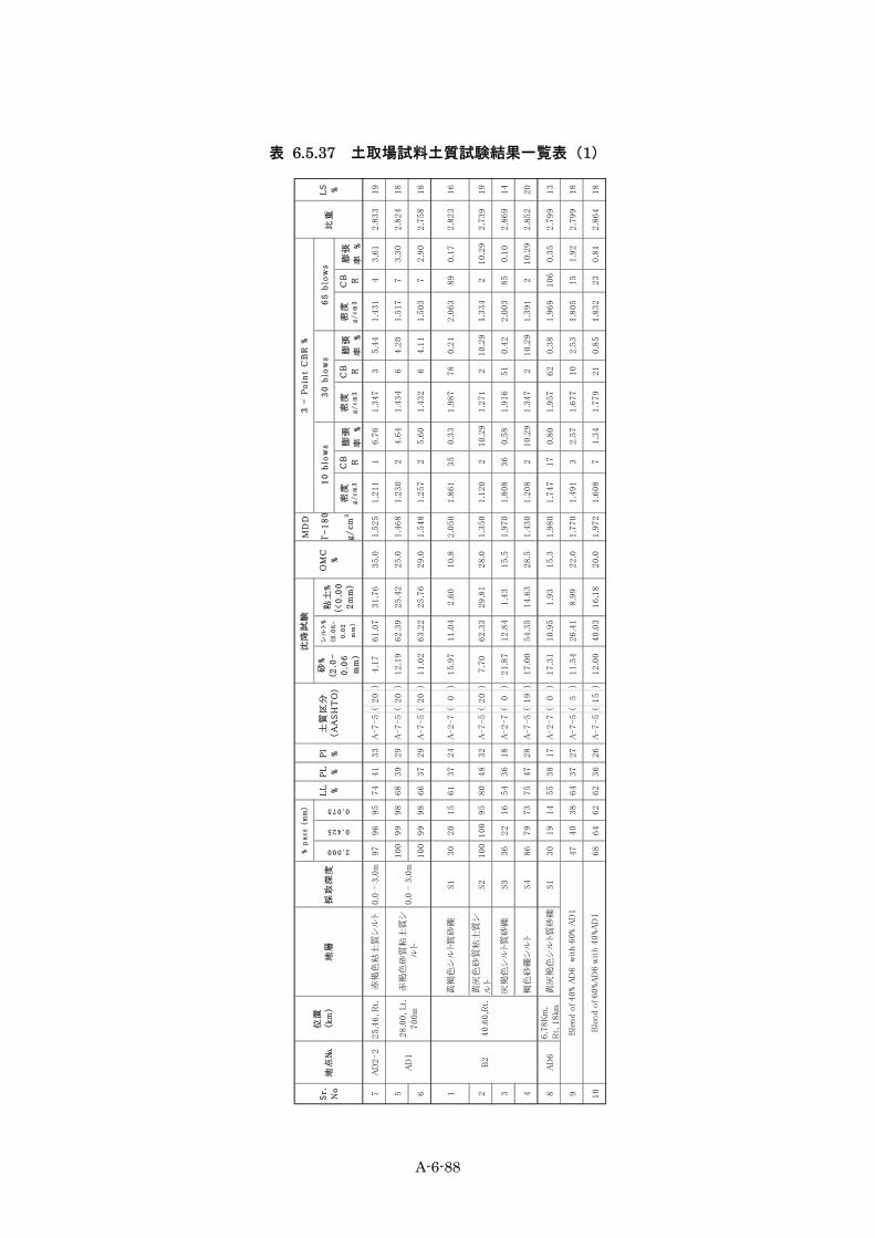
A-6-88
表 6.5.37 土取場試料土質試験結果一覧表(1)
MD
D
T-
18
0
g/
cm
3密
度g
/c
m3
CB R
膨張
率
%
密度
g/
cm
3
CB R
膨張
率
%
密度
g/
cm
3
CB R
膨張
率
%
7A
D2-2
25.4
6, R
t.赤
褐色
粘土
質シ
ルト
0.0
- 3
.0m
97
96
95
74
41
33
A-7-5
(20
)4.1
761.0
731.7
635.0
1.5
25
1.2
11
16.7
61.3
47
35.4
41.4
31
43.6
12.8
33
19
5100
99
98
68
39
29
A-7-5
(20
)12.1
962.3
925.4
225.0
1.4
68
1.2
30
24.6
41.4
34
64.2
01.5
17
73.3
02.8
24
18
6100
99
98
66
37
29
A-7-5
(20
)11.0
263.2
225.7
629.0
1.5
48
1.2
57
25.6
01.4
32
64.1
11.5
03
72.9
02.7
58
18
1黄
褐色
シル
ト質
砂礫
S1
30
20
15
61
37
24
A-2-7
(0
)15.9
711.0
42.6
010.8
2.0
50
1.8
61
35
0.3
31.9
87
78
0.2
12.0
63
89
0.1
72.8
23
16
2黄
灰色
砂質
粘土
質シ
ルト
S2
100
100
95
80
48
32
A-7-5
(20
)7.7
062.3
329.8
128.0
1.3
50
1.1
20
210.2
91.2
71
210.2
91.3
34
210.2
92.7
39
19
3灰
褐色
シル
ト質
砂礫
S3
36
22
16
54
36
18
A-2-7
(0
)21.8
712.8
41.4
315.5
1.9
70
1.8
08
36
0.5
81.9
16
51
0.4
22.0
03
85
0.1
02.8
69
14
4褐
色砂
礫シ
ルト
S4
86
79
73
75
47
28
A-7-5
(19
)17.0
054.3
514.6
328.5
1.4
30
1.2
08
210.2
91.3
47
210.2
91.3
91
210.2
92.8
52
20
8A
D6
6.7
8K
m,
Rt.
18km
黄灰
褐色
シル
ト質
砂礫
S1
30
19
14
55
38
17
A-2-7
(0
)17.3
110.9
51.9
315.3
1.9
80
1.7
47
17
0.8
01.9
57
62
0.3
81.9
69
106
0.3
52.7
99
13
947
40
38
64
37
27
A-7-5
(5
)11.5
426.4
18.9
922.0
1.7
70
1.4
91
32.5
71.6
77
10
2.5
31.8
05
15
1.9
22.7
99
18
10
68
64
62
62
36
26
A-7-5
(15
)12.0
040.0
316.1
820.0
1.9
72
1.6
08
71.3
41.7
79
21
0.8
51.8
32
23
0.8
12.8
64
18
砂%
(2.0
-
0.0
6
mm
)
比重
Ble
nd o
f 40% A
D6 w
ith 6
0% A
D1
Ble
nd o
f 60%A
D6 w
ith 4
0%A
D1
65
blo
ws
シル
ト%
(0.0
6-
0.0
2
mm
)
LS %
2.000
0.425
3 -
Po
int
CB
R %
% p
ass (
mm
)沈
降試
験
粘土
%
(<0
.00
2m
m)
OM
C
%
10
blo
ws
30
blo
ws
Sr.
No
0.0
- 3
.0m
28.0
0, Lt.
700m
赤褐
色砂
質粘
土質
シ
ルト
採取
深度
B2
AD
1
PL %
PI %
土質
区分
(A
AS
HT
O)
0.075
位置
(km
)L
L %地
層地
点№
40.6
0,R
t.

A-6-89
表 6.5.38 土取場試料土質試験結果一覧表(2)
MD
D
T-
18
0
g/
cm
3密
度g
/c
m3
CB R
膨張
率
%
密度
g/
cm
3
CB R
膨張
率
%
密度
g/
cm
3
CB R
膨張
率
%1
0 - 1
m (S
1)10
010
098
6335
28A
-7-5
(19
)26
.01.
400
1.20
21
2.43
1.34
39
2.30
1.43
415
1.97
2.68
718
21
- 2m
(S2)
100
9998
7034
36A
-7-5
(20
)11
.94
50.3
237
.74
30.5
1.50
01.
280
42.
471.
410
102.
301.
494
190.
942.
709
203
2 - 3
m (S
3)99
9796
6935
34A
-7-5
(20
)-
--
29.0
1.45
81.
260
25.
141.
357
44.
521.
428
62.
982.
725
204
0 - 2
m (S
1)10
099
9770
3436
A-7
-5(
20)
--
-26
.51.
525
1.21
81
7.10
1.39
23
7.04
1.48
24
4.45
2.78
620
52
- 3m
(S2)
7065
6367
3730
A-7
-5(
16)
--
-25
.51.
653
1.38
53
2.66
1.60
19
2.35
1.65
411
2.12
2.78
619
63
- 4m
(S3)
100
9996
7235
37A
-7-5
(20
)11
.01
46.9
042
.09
29.5
1.48
01.
238
37.
861.
393
46.
281.
468
44.
042.
941
197
0 - 1
m (S
1)96
9593
6233
29A
-7-5
(20
)9.
5064
.65
25.8
630
.01.
520
1.25
43
3.20
1.39
99
2.66
1.53
011
2.02
2.73
218
81
- 2m
(S2)
7167
6567
4225
A-7
-5(
15)
--
-32
.01.
519
1.39
08
1.71
1.46
512
1.28
1.50
713
1.11
2.86
518
92
- 3m
(S3)
8075
7266
3729
A-7
-5(
19)
--
-27
.51.
549
1.34
97
3.48
1.45
610
2.93
1.51
410
2.38
2.89
018
10A
D811
.36,
Lt.
370m
灰色
シル
ト質
砂礫
S140
3432
6038
22A
-2-7
(2
)9.
0828
.86
2.38
20.2
1.64
01.
446
46.
021.
551
45.
491.
667
53.
772.
900
16
11A
D911
.36,
Lt.
570m
黄褐
色シ
ルト
質砂
礫S1
5835
3066
4719
A-2
-7(
1)
29.4
525
.96
2.60
19.3
1.78
01.
359
101.
021.
499
390.
981.
595
550.
942.
793
11
12S1
9795
9370
3535
A-7
-5(
20)
--
-27
.01.
542
1.26
62
7.51
1.43
94
6.50
1.55
34
3.42
2.74
120
13S2
100
9688
7040
30A
-7-5
(20
)15
.28
49.4
725
.88
27.5
1.60
11.
294
32.
441.
496
54.
971.
563
65.
962.
915
18
LL
=液
性限
界、
PL
=塑
性限
界、
PI=
塑性
指数
、O
MC
=最
適含
水比
、M
DD
=最
大乾
燥密
度、
LS=線
収縮
限界
AD7
9.00
, Rt.
2.5k
m
赤褐
色粘
土質
シル
ト
褐色
砂質
シル
ト質
粘
土
赤褐
色砂
質粘
土質
シ
ルト
赤黄
褐色
砂質
シル
トA
D10
PL %
1.68
, Lt.
800m
LS %
2.000
0.425
0.075
砂%
(2.0
-
0.0
6
mm
)
シル
ト%
(0.0
6-
0.0
2
mm
)
粘土
%
(<0
.00
2m
m)
1
0 b
low
s6
5 b
low
sP
I %
土質
区分
(A
AS
HT
O)
沈降
試験
OM
C
%
3 -
Po
int
CB
R %
30
blo
ws
比重
Sr.
No
地点
№
位置
(km
)地
層採
取深
度
% p
ass (
mm
)
LL %

A-6-90
表 6.5.39 消石灰混入試験に対する CBR 試験結果
% ラ
イム
LL %
PL %
PI %
LL %
PL %
PI %
密度
g/
cm
3C
BR
膨張
率
%
密度
g/
cm
3C
BR
膨張
率
%
密度
g/
cm
3C
BR
膨張
率
%
12%
65
46
19
79
51
28
25.0
1.5
05
1.2
48
20.1
21.2
60
40.1
81.3
08
90.3
9
24%
52
42
10
65
48
17
25.0
1.5
01
1.3
96
20.2
71.3
92
14
0.1
31.4
15
11
0.2
5
36%
56
42
14
64
50
14
24.0
1.4
90
1.5
13
30.7
21.4
73
17
0.2
11.4
95
17
0.1
2
42%
71
46
25
67
47
20
18.0
1.5
62
1.2
54
41.0
81.5
64
60.9
81.6
36
11
0.9
4
54%
53
42
11
59
47
12
23.0
1.5
60
1.3
27
60.1
21.4
54
12
0.2
51.5
54
19
0.1
3
66%
51
44
751
46
523.0
1.5
40
1.3
04
11
0.2
01.4
32
20
0.2
11.5
09
50
0.1
5
72%
68
45
23
71
47
24
30.0
1.4
48
1.2
06
30.2
31.3
46
60.2
11.4
35
70.1
5
84%
54
41
13
57
46
11
33.0
1.3
95
1.1
95
70.2
11.3
29
16
0.1
81.4
01
31
0.1
3
96%
50
46
453
46
732.0
1.3
69
1.1
77
13
0.3
21.3
30
42
0.1
21.4
04
64
0.1
1
NT
P30
(ET
P3)
赤色
シル
ト質
粘土
を帯
状に
混入
する
暗
灰色
シル
ト質
粘土
1
0 b
low
s3
0 b
low
s6
5 b
low
s
アッ
ター
ベル
グ試
験
NT
P 2
(ET
P1)
暗灰
色シ
ルト質
粘土
NT
P 1
3
(ET
P2)
暗灰
色シ
ルト質
粘土
Sr.
No
地点
№地
層
3 -
Po
int
CB
R %
消
石灰
によ
る安
定化
試料
Befo
re C
BR
Aft
er
CB
R
OM
C
%
MD
D
T-
18
0
g/
cm
3
A-6-91
‐盛土材料 アベヤ川、イエダ川などの沖積低地では高さ 3m程度の盛土が計画されている。一般に盛土材料
としては地盤強度が大きく、圧縮性が小さく、かつ自然含水比が最適含水比に近い材料が望ましい。
さらに施工時のトラフィカビリティなどの考慮も必要となる。これらをほほ満足させる材料として
は B2 のシルト質砂礫(玄武岩の強風化帯)及び AD1,AD7 の砂混じりシルト質赤色土である。AD6の礫質土も良好な材料であるが、国道 A3 線より約 18kmも離れており、運搬上の問題がある。
AD9 の礫質土も良好であるが賦存量(15000m3)が極めて少ない。また AD7 の赤色土はシルト質
でありかつ強度も十分にあり利用可能である。
‐置き換え材料 本ルート上には低地及び台地の一部にブラックコットンソイルが分布する。ブラックコットンソ
イルはすでに述べたように、膨張性が高く、強度(CBR2 以下)も低い。これらは良質土で置き換
える必要があるが、置き換え材料として、エチアピア国 ERA 野外調査マニュアル(2002)によっ
て次のような規定がある。 CBR=5 以上 また上記の規定には含まれないが水によるブラックコットンソイルの膨張収縮をおさえるため
にある程度透水性の低い材料が必要とされる。AD7 の赤色土は砂混じりシルトであり、透水性の
低いことが期待される。またつき固めた試料の CBR 値も高い。
‐ライム混合試料 CBR 試験結果 デジェンの台地(ETP1)、アベヤ川(ETP2)、イエダ川(ETP3)で採取したブラックコットンソ
イルに各々2%、4%、6%のライム(消石灰)を混入し、CBR 試験を実施した。調査結果から明ら
かなように 4%以上のライムの混入によって、塑性指数 PI は 20%以下となり CBR 値は 5 以上に増
加し、膨張率は著しく低下した。改良効果は著しいものがあるが、施工コストの大幅な増大を招く
ものと思われる。
‐透水試験結果(変水位法) 土取場試料 AD1,AD6,AD7,AD9 及び AD10 の透水試験結果を表 6.5.40に示す。詳細設計時に更に
詳細な調査を実施する予定である。

A-6-92
表 6.5.40 透水試験結果
シリアル
№
テストピット
№ 試料№ 深度(m)
最大乾燥密
度(kg/m3)
透水係数 K
(cm/sec) 地層名
1 AD7(TP1) S-1 0.00-1.00 1375 2.50×10⁻⁵ 赤褐色粘土質シルト
2 AD7(TP1) S-2 1.00-2.00 1380 2.53×10⁻⁵ 赤褐色粘土質シルト
3 AD7(TP1) S-3 2.00-3.00 1364 2.47×10⁻⁵ 赤褐色粘土質シルト
4 AD7(TP2) S-1 0.00-2.00 1368 2.49×10⁻⁵ 赤褐色粘土質シルト
5 AD7(TP2) S-2 2.00-3.00 1362 2.46×10⁻⁵ 赤褐色粘土質シルト
6 AD7(TP2) S-3 3.00-4.00 1392 2.50×10⁻⁵ 赤褐色粘土質シルト
7 AD7(TP3) S-1 0.00-1.00 1360 2.46×10⁻⁵ 赤褐色粘土質シルト
8 AD7(TP3) S-2 1.00-2.00 1380 2.23×10⁻⁵ 赤褐色粘土質シルト
9 AD7(TP3) S-3 2.00-3.00 1390 2.44×10⁻⁵ 赤褐色粘土質シルト
10 AD9 S-2 ‐ 1498 1.05×10⁻⁵ 黄灰色シルト質砂礫
11 AD10 S-1 ‐ 1370 2.49×10⁻⁵ 赤褐色粘土質シルト
12 AD10 S-2 ‐ 1395 2.48×10⁻⁵ 赤褐色粘土質シルト
13 AD1 ‐ ‐ 1370 2.49×10⁻⁵ 赤褐色粘土質シルト
14 AD1+AD6 混合試料 (40%+60%) 1834 4.69×10⁻⁵ 赤褐色シルト質砂礫
15 AD1+AD6 混合試料 (60%+40%) 1794 4.19×10⁻⁶ 赤褐色シルト質砂礫