Embed Size (px)
Citation preview

Agenda and Objectives
Trane Engineers Newsletter Live Series
Ice Storage Design and Application
The electrical supply chain of the future will incorporate a higher percentage of renewable energy (i.e. wind and PV solar).
While clean and unlimited, these forms of energy are intermittent in nature and will require some form of energy storage
to meet their potential. Thermal storage is not only an easy way to store energy but it is reemerging as a valuable energy
and energy cost saving technology for building owners.
We’ll cover a bit of theory and application, then demonstrate the design steps for a small ice storage system from layout
to operation and control. We’ll discuss how to make it affordable, expose hidden costs in energy tariffs which raise ROI,
and identify and address the most common stumbling blocks.
By attending this ENL you will be able to:
1. Provide a clear understanding of how an ice storage system operates
2. Provide an economic rationale for ice storage
3. Dispel common myths about ice storage
4. Understand how to avoid the most common stumbling blocks
Agenda
1) Opening (welcome, agenda, introductions)
2) Why ice storage
a) Electrical infrastructure
b) Economics
c) Environmental stewardship
d) Myths about ice storage
3) Typical applications
4) Electricity rate introduction
5) Design overview
a) Partial versus full
b) Influences driving partial storage
c) Influences driving full storage
d) Considerations
6) Controls
4) Economic summary
Agenda_APPCMC036.ai 1 6/19/2014 11:22:59 AM

Presenters
Trane Engineers Newsletter Live Series
Ice Storage Design and Application(2009)
Susanna Hanson | applications engineer | Trane
Susanna is an applications engineer at Trane with over eleven years of experience with chilled-water systems and HVAC building
load and energy analysis. Her primary responsibility is to aid system design engineers and Trane personnel in the proper design
and application of HVAC systems. Her main areas of expertise include chilled-water systems and ASHRAE Standard 90.1.
She is also a Certified Energy Manager.
She has authored several articles on chilled water plant design, and is a member of ASHRAE SSPC 90.1 Energy Standard for
Buildings Except Low-Rise Residential Buildings. Susanna earned a bachelor’s degree in industrial and systems engineering from
the University of Florida, where she focused on building energy management and simulation.
Lee Cline | senior systems engineer | Trane
Lee is an engineer in the Systems Engineering Department with over 28 years experience at Trane. His career at Trane started
as a factory service engineer for heavy refrigeration, helping to introduce the CVHE centrifugal chiller with electronic controls
to the industry. Following that Lee was a member of the team that kicked off the microelectronic building automation and
Integrated Comfort Systems controls – ICS - offering at Trane. He continues to push new unit and system control and
optimization concepts into the industry. As a Systems Engineer Lee also has the opportunity to discuss HVAC system
application and control with owners, engineers and contractors on a daily basis.
Lee has a Bachelors degree in Mechanical Engineering from Michigan Technological University. He is a Registered
Professional Engineer in the State of Wisconsin.
Paul Valenta | Vice-President Sales and Marketing | CALMAC Mfg. Corp.
Paul is a vice-president at CALMAC Manufacturing Corporation with over 20 years experience in the ice energy field. CALMAC
celebrated its 60th birthday in 2008 and has a long history of providing valuable energy saving products. Paul’s career at
CALMAC started as a regional sales manager responsible for sales and distribution of ice storage systems in the Midwest.
Without utility incentives and off peak rates, Paul specialized in developing partial ice energy storage applications in schools
and offices and demonstrating their viability with life cycle costs. He has been involved in several hundred ice storage
projects all over the world. Currently Paul is Marketing and Sales Manager for CALMAC. He has authored several articles
on ice energy storage and rightsizing cooling plants with energy storage, is a member or ASHRAE and is a LEED Accredited
Professional. Paul has a degree in Electrical Engineering from the University of Nebraska.
Biographies_APPCMC036.ai 1 6/19/2014 11:22:13 AM

Ice Storage and Application© 2009 Trane, a business of Ingersoll-Rand. 1
Ice Storage Design and Application
EngineersNewsletter Live
© 2009 Trane2
© 2008 Trane Inc.
“Trane” is a Registered Provider with The American Instituteof Architects Continuing Education Systems. Credit earned on completion of this program will be reported to CES Records for AIA members. Certificates of Completion for non-AIA members available on request.
This program is registered with the AIA/CES for continuing professional education. As such, it does not include content that may be deemed or construed to be an approval or endorsement by the AIA of any material of construction or any method or manner of handling, using, distributing, ordealing in any material or product.Questions related to specific materials,methods, and services will be addressedat the conclusion of this presentation.

Ice Storage and Application© 2009 Trane, a business of Ingersoll-Rand. 2
© 2009 Trane3
Copyrighted Materials
This presentation is protected by U.S. and international copyright laws. Reproduction, distribution, display, and use of the presentation without written permission of Trane is prohibited.
© 2009 Trane, Inc. All rights reserved.
© 2009 Trane4
Ice Storage Design and Application
Today’s Topics
Overview—why ice now?
Typical applications
Qualifying a job
Design process
Minimizing first cost, maximizing ROI
Project level considerations
Controls
Economics

Ice Storage and Application© 2009 Trane, a business of Ingersoll-Rand. 3
© 2009 Trane5
Today’s Presenters
Lee Cline
SystemsEngineer
Paul Valenta
Calmac NationalSales Manager
Susanna Hanson
Applications Engineer
Ice Storage Design and Application
Why Ice Storageand Why Now?
Ice Storage and Application© 2009 Trane, a business of Ingersoll-Rand. 4
© 2009 Trane7
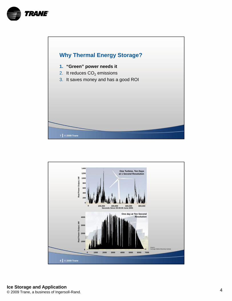
Why Thermal Energy Storage?
1. “Green” power needs it
2. It reduces CO2 emissions
3. It saves money and has a good ROI
© 2009 Trane8
1400
1200
1000
800
600
400
200
0
Rea
l Po
wer
Ou
tpu
t, k
W
Seconds Since 00:00:00 June 2005
One Turbine, Ten Days at 1 Second Resolution
0 200,000 400,000 600,000 800,000
Rea
l Po
wer
Ou
tpu
t, k
W
One day at Ten Second Resolution
0 1000 2000 3000 4000 5000 6000 7000
4000
3000
2000
1000
0Source:Carnegie Mellon Electricity Institute

Ice Storage and Application© 2009 Trane, a business of Ingersoll-Rand. 5
© 2009 Trane9
Source: Carnegie Mellon Research Institute
© 2009 Trane10
Source: Carnegie Mellon Research Institute

Ice Storage and Application© 2009 Trane, a business of Ingersoll-Rand. 6
© 2009 Trane11
Why Thermal Energy Storage?
1. “Green” power needs it
2. It reduces CO2 emissions
3. It saves money and has a good ROI
Simulation of Source Energy Utilization and Emissions for HVAC Systems
A report ASHRAE TC 6.9 in response to the 991-TRP work statement
© 2009 Trane12
ASHRAE TC 6.9 Research Project
Monthly Power Plant Fuel Source
Coal Dominate Generation(MG&E Profile)
Balanced Generation(WEPCO Profile)
800
700
600
500
400
300
200
100
0
800
700
600
500
400
300
200
100
0
1 12 1 12month month
ho
ur
ho
ur

Ice Storage and Application© 2009 Trane, a business of Ingersoll-Rand. 7
© 2009 Trane13
ASHRAE TC 6.9 Research Project
Ice Storage Site, Source, & CO2 Savings
System
Coal Dominant Utility Generation Profile
Coal/Natural Gas Utility Generation Profile
SiteElectricity(% of base)
SourceEnergy
(% of base)
CO2
Emission(% of base)
SiteElectricity(% of base)
SourceEnergy
(% of base)
CO2
Emission(% of base)
Electric Chiller(base)
100% 100% 100% 100% 100% 100%
OfficeIce Storage
86% 86% 86% 86% 86% 86%
SchoolW/C—Ice
88% 88% 87% 88% 88% 88%
SchoolA/C—Ice
87% 87% 86% 87% 87% 88%
© 2009 Trane14
“Thermal energy storage systems should be promoted as an environmentally beneficial technology. These systems have been historically touted as beneficial in terms of operation cost. This study suggests that the economic benefits can be accompanied by environmental ones…”
“…Source energy reductions were generally on the order of 10%. Global warming impact reductions were also on the order of 10%...”
Simulation of Source Energy Utilization and Emissions for HVAC Systems
Conclusions

Ice Storage and Application© 2009 Trane, a business of Ingersoll-Rand. 8
© 2009 Trane15
Why Thermal Energy Storage?
1. “Green” power needs it
2. It reduces CO2 emissions
3. It saves money and has a good ROI
© 2009 Trane16
Why Concentrate on Ice?
Thermal Storage Incremental Cost
Thermal Storage – Installed Ton Hours
Co
st P
er T
on
Ho
ur
1. Rapid discharge2. Emergency use
Chilled Water
Modular Ice

Ice Storage and Application© 2009 Trane, a business of Ingersoll-Rand. 9
Ice Storage Design and Application
Ice StorageOverview
Paul Valenta
© 2009 Trane18
Energy Storage Background
Ice harvesters
Ice on pipe—external melt
Encapsulated ice storage
Modular ice on pipe —internal melt

Ice Storage and Application© 2009 Trane, a business of Ingersoll-Rand. 10
© 2009 Trane19
Six Modes of Energy Storage Systems
1. Charging
2. Charging and cooling a night time load
3. Chiller cooling
4. Energy storage cooling
5. Chiller and energy storage cooling
6. Off
© 2009 Trane20
Ice on Pipe—Internal Melt
Strengths Six modes of operation
Efficient, modular, reliable
Cataloged data
Fast installation
Weaknesses Secondary heat transfer fluid
Not easily direct buried

Ice Storage and Application© 2009 Trane, a business of Ingersoll-Rand. 11
© 2009 Trane21
Ice on Coil—Internal Melt
Easily adapts to chilled-water system
Added:
• Blending valve
• Diverting valve
• Ice tank(s)
• Controls
• Heat transfer fluid
Temperature
Control Valve
© 2009 Trane22
Ice Building and Melting Cycle Ice on Pipe—Internal Melt

Ice Storage and Application© 2009 Trane, a business of Ingersoll-Rand. 12
© 2009 Trane23
Rules of Thumb for Partial Ice Storage Designs
Most projects are partial storage unless utilities support full storage with rebates
Chiller loses 1/3 of capacity during ice build
Ice making time is usually 8 to 10 hours
Typical systems store about 1/4 to 1/3 of the total design day ton-hours
Chiller reduction• To 50% in schools, 35%–40% office buildings
Design for high delta T, 15°F to 18°F
Ice Storage Design and Application
Design OverviewSusanna Hanson

Ice Storage and Application© 2009 Trane, a business of Ingersoll-Rand. 13
© 2009 Trane25
Visualize the Potential Impact
Building kW load duration curve
Diversity factor• Average load/peak load
• Total kW
• HVAC kW
• Chiller tons
k-12 school
average
peak200
100
0
total kW
cooling kW
© 2009 Trane26
University of Arizona
21 chillers33,000 tons
156 ice tanks23,400 ton-hours
Ice storagesaves $423,000/year
Self-generates at 4–5 cents/kWh
Purchases at 7.5-8.5 cents/kWh
Ice flattens load profile for utility rate negotiation

Ice Storage and Application© 2009 Trane, a business of Ingersoll-Rand. 14
© 2009 Trane27
Design Day Load Profile
0
100
200
300
400
500
600
700
800
900
Time
Ton
s
© 2009 Trane28
How Much Chiller Capacity?
0
100
200
300
400
500
600
700
800
900 Idle Chiller Capacity
Design Day Cooling Load profile
Conventional System(3)—240 ton chillers
Time
Ton
s

Ice Storage and Application© 2009 Trane, a business of Ingersoll-Rand. 15
© 2009 Trane29
Comparable Ice Storage Design
0
100
200
300
400
500
600
700
800
900 Storage System Excess Capacity
Design Day Load
Storage System(2)—240 ton chillers2,130 ton-hrs. storage
Time
Ton
s
© 2009 Trane30
Comparable Ice Storage Design
0
100
200
300
400
500
600
700
800
900
Conventional System (3) 240 ton chillers
Storage System Excess Capacity
Design Day Load
Time
Ton
s
Storage System(2)—240 ton chillers2,130 ton-hrs. storage

Ice Storage and Application© 2009 Trane, a business of Ingersoll-Rand. 16
© 2009 Trane31
Time
Ton
s
Conventional2 (3)—240 ton chillers
Design Day With Chiller Outage
0
100
200
300
400
500
600
700
800
Storage Chiller
Stored Cooling
Storage System Shortfall
© 2009 Trane32
Time
Ton
s
Storage System1 (2) 240 ton chillers2,130 ton-hr storage
Design Day With Chiller Outage
0
100
200
300
400
500
600
700
800
Storage Chiller
Stored Cooling
Storage System Shortfall

Ice Storage and Application© 2009 Trane, a business of Ingersoll-Rand. 17
© 2009 Trane33
Design OverviewFull Storage
Short on-peak windows or
Good rebates available
downsized chiller
makeice
meltice
chiller
chiller capacity
midnight 6 a.m.
makeice
makeice
meltice
chiller
chiller capacity
downsized chillermidnight
Partial Storage
Reduces peak demand
Shifts load to more efficient time
© 2009 Trane34
Air-cooled or Water-cooled?
Not that much design difference
Air-cooled • Reduces initial investment for efficient system
• Fewer components to select
Water-cooled• Large chiller capacities (>500 tons)
• May require multiple stages of compression
• Expanded economizer cycle

Ice Storage and Application© 2009 Trane, a business of Ingersoll-Rand. 18
© 2009 Trane35
Expand “Free” Cooling Cycle
Ice extends the hours for water economizer free cooling cycle
Reduces tower energy by charging tanks at night with fans unloaded
© 2009 Trane36
Condenser Relief
Ice Making
Dry Bulb
Wet BulbIce
Making
WB design
DB design
RELIEF
65
70
75
80
85
90
95
1 2 3 4 5 6 7 8 9 10 11 12 13 14 15 16 17 18 19 20 21 22 23 24
Typical August Day in Memphis
Tem
per
atu
re

Ice Storage and Application© 2009 Trane, a business of Ingersoll-Rand. 19
© 2009 Trane37
EERLeaving Solution Temp and Ambient Relief
7
8
9
10
11
12
13
14
15
20 25 30 35 40 45 50 55
Leaving Solution Temp (F)
EE
R 95 Air
85 Air
75 Air
© 2009 Trane38
Fossil Ridge High School
260,000 ft2 conditioned space
Grades 10–12
1,800 students
• Rule of thumb
• 400 sq. ft./ton
Peak load—250 Tons
• 1,040 sq. ft./ton
Actual chiller—130 tons, 1,280 ton hrs ice storage
• 2,000 sq. ft./ton

Ice Storage and Application© 2009 Trane, a business of Ingersoll-Rand. 20
© 2009 Trane39
Retrofits
Chillers/systems being replaced anyway• Ice chillers of equal capacity cost the same
• Cost less if downsize the chillers
Energy prices are high
Energy shortages are common
Rebates or incentives are available• States (California, New York)
• Utilities (Duke Power, FPL)
© 2009 Trane40
Simple Air-Cooled Chilled Water System
Chiller
Downstream ice tanks
Blending valve
Diverting valve
Controls
Heat transfer fluid

Ice Storage and Application© 2009 Trane, a business of Ingersoll-Rand. 21
© 2009 Trane41
Ice Tanks in SeriesDownstream of Screw/Scroll Chiller
ICEBANK
air handlers
V1V2
P1
P2
back pressure regulating valve
© 2009 Trane42
Ice Tanks in Series Upstream of Centrifugal Chiller
air handlers
V2
P1
P2
V1A
B
C
A
B C
regulating valve

Ice Storage and Application© 2009 Trane, a business of Ingersoll-Rand. 22
© 2009 Trane43
Ice and Chillers in Series
Chiller in upstream position:• Increases chiller efficiency (screws more than CTVs)• Increases chiller capacity (screws more than CTVs)• Decreases ice capacity• Simplifies system layout• Tank capacity loss doesn’t exceed chiller efficiency and
capacity benefits• Smaller system, screw or scroll—tanks downstream
Chiller in downstream position:• Decreases chiller efficiency• Decreases chiller capacity• Increases ice capacity (reduced number of tanks?)• Tank capacity benefit is substantial• Larger system, centrifugals—tanks upstream
S.I.C.
Ice Storage Design and Application
QualifyingLee Cline

Ice Storage and Application© 2009 Trane, a business of Ingersoll-Rand. 23
© 2009 Trane45
Qualify Job
Ice Storage Design Process
• New/existing• Preliminary
load profile• Peak• Daily curve
•Utility rate•Future use
AcquireData
TargetProspective
Job
• Chilled water • Doing
something• Utility cost
conscious• Day loading• Tank siting • Code
compliance
• Ice Pick
InitialSystemSizing
InitialFinancialAnalysis
• SystemAnalyzer
• First Pass
InitialFinancialProposal
•Proforma•ROI•Schedule
© 2009 Trane46
Ice Energy Storage Design
Project Specifics
Chilled water
Building usage and future plans• Emergency cooling
• Enhanced redundancy
• Expansion
• Green energy
• Teaching tool

Ice Storage and Application© 2009 Trane, a business of Ingersoll-Rand. 24
© 2009 Trane47
Ice Energy Storage Design
Project Specifics
Chilled water
Building usage and future plans
Space for tank farm• Outside
• Inside
• Stacked
• Partial or complete burial
© 2009 Trane48
Ice Energy Storage Design
Project Specifics
Chilled water
Building usage and future plans
Space for tank farm
System distribution design• Glycol throughout system
• Wide delta T/low flow / low temp
• Constant/variable flow
• Dedicated ice/cooling chillers

Ice Storage and Application© 2009 Trane, a business of Ingersoll-Rand. 25
© 2009 Trane49
Qualify Job
Ice Storage Design Process
• New/existing• Preliminary
load profile• Peak• Daily curve
•Utility rate•Future use
AcquireData
TargetProspective
Job
• Chilled water • Doing
something• Utility cost
conscious• Day loading• Tank siting • Code
compliance
• Ice Pick
InitialSystemSizing
InitialFinancialAnalysis
• SystemAnalyzer
• First Pass
InitialFinancialProposal
•Proforma•ROI•Schedule
© 2009 Trane50
Ice Energy Storage Design
Acquire Data
Cooling load • Design day hourly profile Tall peak?
Low and flat?
Off peak usage?
Acquire from…• Load program
• Chiller logs
• BAS logs
July
75°
Partn/Floors
Rooms
Roofs
Walls
Int. Loads
AirflowsInt. Loads

Ice Storage and Application© 2009 Trane, a business of Ingersoll-Rand. 26
Ice Storage Design and Application
Qualifying Preliminary Analysis
Paul Valenta
© 2009 Trane52
Ice Energy Storage Design
Cooling Load
24 hour design day load profile from• Load program
• Chiller logs
• BAS logs
Night loads• > 20% of peak loads
• If > 20% consider night chiller
July
75°
Partn/Floors
Rooms
Roofs
Walls
Int. Loads
AirflowsInt. Loads

Ice Storage and Application© 2009 Trane, a business of Ingersoll-Rand. 27
© 2009 Trane53
Internal-Melt Tank Dynamics
Performance dependencies• Flow rate
• Temperatures
• Ice capacity remaining
Performance requirements• Peak discharge rate
• Hourly discharge rate
• Total storage capacity
© 2009 Trane54
Equipment Selection Criteria
Heat transfer fluid type and concentration
Ice tank model
Chiller daytime contribution as a % of nominal
Chiller charging capacity as a % of nominal
Supply and Return delta T
24 hour load profile• Full or partial storage

Ice Storage and Application© 2009 Trane, a business of Ingersoll-Rand. 28
© 2009 Trane55
IcePick—Input Screens
© 2009 Trane56
Design Day Load Profile

Ice Storage and Application© 2009 Trane, a business of Ingersoll-Rand. 29
© 2009 Trane57
Equipment Selection Example
© 2009 Trane58
Equipment Selection Example

Ice Storage and Application© 2009 Trane, a business of Ingersoll-Rand. 30
© 2009 Trane59
Equipment Selection Example
© 2009 Trane60
Design Day Analysis

Ice Storage and Application© 2009 Trane, a business of Ingersoll-Rand. 31
© 2009 Trane61
Ice Storage Selection Options
46 ton nominal chiller/3 ice tanks
58 ton nominal chiller/2 ice tanksLess charging time
Demand limit chiller on peak day
or
70 ton nominal chiller/3 ice tanksHigher first cost
Will it pay back?
or
Ice Storage Design and Application
Qualifying Design—Utility Rates
Lee Cline

Ice Storage and Application© 2009 Trane, a business of Ingersoll-Rand. 32
© 2009 Trane63
Qualify Job
Ice Storage Design Process
• New/existing• Preliminary
load profile• Peak• Daily curve
•Utility rate•Future use
AcquireData
TargetProspective
Job
• Chilled water • Doing
something• Utility cost
conscious• Day loading• Tank siting • Code
compliance
• Ice Pick
InitialSystemSizing
InitialFinancialAnalysis
• SystemAnalyzer
• First Pass
InitialFinancialProposal
•Proforma•ROI•Schedule
© 2009 Trane64
Ice Energy Storage Design
Acquire Data
Cooling load
Utility rates• kW charge—Ratcheted?
• On-Peak/Off-Peak—kW and/or KWh
• Real time pricing
• Up front or on-going incentives

Ice Storage and Application© 2009 Trane, a business of Ingersoll-Rand. 33
© 2009 Trane65
Ice Energy Storage Design
Monthly Load Factor
Month's kWh Usage _
Peak Demand (kW) x 730 hours per month
© 2009 Trane66
Ice Energy Storage Design
Monthly Load Factor
Load Factor = 63 Load Factor = 37
0
10
20
30
40
5060
7080
Lo
ad (
Ton
s)
1 3 5 7 9 11 13 15 17 19 21 23
Hour
High Load Factor
0
10
20
30
4050
60
7080
Lo
ad (
Ton
s)
1 3 5 7 9 11 13 15 17 19 21 23
Hour
Low Load Factor

Ice Storage and Application© 2009 Trane, a business of Ingersoll-Rand. 34
Ice Storage Design and Application
Qualifying RatesPaul Valenta
© 2009 Trane68
Electric Rates and Types
Demand rate—most common• Ratchet
• Time of day

Ice Storage and Application© 2009 Trane, a business of Ingersoll-Rand. 35
© 2009 Trane69
$ 11.00/kW and $.08/kWh*
Ton-hr Cost on a Standard Demand Rate
Nighttime Costs Daytime Costs
Demand Cost $/kWhEnergy Cost $/kWh Ton-hr cost $/Tn. Hr.
$.016
$.08
$.108
$.1884
$.08$.08
$.06
$.00
* Assumes building with daytime peak
© 2009 Trane70
Electric Rates and Types
Demand rate—most common• Ratchet
• Time of day
Stepped rate

Ice Storage and Application© 2009 Trane, a business of Ingersoll-Rand. 36
© 2009 Trane71
Georgia Power Electric Rates PLM-4 All consumption (kWh) not greater than
200 hours times the billing demand:First 3,000 kWh .................................................................@...................... 9.317¢ per kWhNext 7,000 kWh .................................................................@.......................8.540¢ per kWhNext 190,000 kWh .............................................................@.......................7.350¢ per kWhOver 200,000 kWh..............................................................@.......................5.696¢ per kWh
All consumption (kWh) in excess of 200hours and not greater than 400 hourstimes the billing demand.................................................. @.......................... 0.949¢ per kWh
All consumption (kWh) in excess of 400hours and not greater than 600 hourstimes the billing demand.................................................. @.......................... 0.715¢ per kWh
All consumption (kWh) in excess of 600hours times the billing demand....................................... @........................... 0.623¢ per kWhMinimum Monthly Bill:
A. $15.00 base charge plus $6.83 per kW of billing demand with a ratchet of 95% of peak
B. Summer demand
© 2009 Trane72
Electric Rates and Types
Demand rate—most common• Ratchet
• Time of day
Stepped rate
Flat rate
Real-time pricing

Ice Storage and Application© 2009 Trane, a business of Ingersoll-Rand. 37
Ice Storage Design and Application
Qualifying ROILee Cline
© 2009 Trane74
Qualify Job
Ice Storage Design Process
• New/existing• Preliminary
load profile• Peak• Daily curve
•Utility rate•Future use
AcquireData
TargetProspective
Job
• Chilled water • Doing
something• Utility cost
conscious• Day loading• Tank siting • Code
compliance
• Ice Pick
InitialSystemSizing
InitialFinancialAnalysis
• SystemAnalyzer
• First Pass
InitialFinancialProposal
•Proforma•ROI•Schedule

Ice Storage and Application© 2009 Trane, a business of Ingersoll-Rand. 38
© 2009 Trane75
Qualify Job
Ice Storage Design Process
• New/existing• Preliminary
load profile• Peak• Daily curve
•Utility rate•Future use
AcquireData
TargetProspective
Job
• Chilled water • Doing
something• Utility cost
conscious• Day loading• Tank siting • Code
compliance
• Ice Pick
InitialSystemSizing
InitialFinancialAnalysis
• SystemAnalyzer
• First Pass
InitialFinancialProposal
•Proforma•ROI•Schedule
© 2009 Trane76
Ice Storage Design Process
DetailedJob
Data
RefineStorageSizing
• Design temps
• RefinedChiller Selection
• Refined Storage Selection• Ice Pick
Detailed Design
RefinedFinancialAnalysis
• Operating modes
• Productionsystem
• Distributionsystem
• Control• Seq• Mode chart• Pts List
DesignWater
System
• TRACE 700• Financial goals
• Detailed loadprofile• Peak• Daily curve
• Utility rate• Future use• Tank location
Commissioning
SystemValidation
• Piping• Controls

Ice Storage and Application© 2009 Trane, a business of Ingersoll-Rand. 39
Ice Storage Design and Application
DesignSusanna Hanson
© 2009 Trane78
Proper Use of Glycol
EG v PG• EG more efficient
• PG less toxic
Affect on coils• New
• Existing
Affect on chillers• Reduced heat transfer
• Reduced flow rates, wider delta T

Ice Storage and Application© 2009 Trane, a business of Ingersoll-Rand. 40
© 2009 Trane79
freeze specificsolution point heat viscosity
water 32°F 1.0 Btu/lb-°F 1.5 cp
ethylene 11.4°F 0.90 Btu/lb-°F 3.2 cpglycol (25%)
propylene 9.3°F 0.92 Btu/lb-°F 5.2 cpglycol (30%)
fluid temperature = 40°F
Proper Use of Glycol
© 2009 Trane80
Proper Use of Glycol
Do you want glycol through the whole building?• Smaller systems—yes Freeze protection in coils (no need for coil pumping)
Not a lot of glycol, avoid HX cost
• Larger systems—maybe not First cost of glycol
Pumping cost
Glycol compatible control valves
Heat exchangers are a one time cost
Head pressure requirements for larger systems

Ice Storage and Application© 2009 Trane, a business of Ingersoll-Rand. 41
© 2009 Trane81
Proper Use of Glycol—Coils
solution
enteringfluid°F
coilrows
totalcapacityMBh
pressuredrop (air)in. H2O
fluidflow rategpm
pressuredrop (fluid)ft. H2O
water 45 6 455 0.64 75.5 6.89
25% EG 45 6 395 0.62 86.4 7.83
© 2009 Trane82
Proper Use of Glycol—Coils
solution
enteringfluid°F
coilrows
totalcapacityMBh
pressuredrop (air)in. H2O
fluidflow rategpm
pressuredrop (fluid)ft. H2O
water 45 6 455 0.64 75.5 6.89
25% EG 45 6 395 0.62 86.4 7.83
25% EG 45 8 455 0.83 86.4 9.81

Ice Storage and Application© 2009 Trane, a business of Ingersoll-Rand. 42
© 2009 Trane83
Proper Use of Glycol—Coils
solution
enteringfluid°F
coilrows
totalcapacityMBh
pressuredrop (air)in. H2O
fluidflow rategpm
pressuredrop (fluid)ft. H2O
water 45 6 455 0.64 75.5 6.89
25% EG 45 6 395 0.62 86.4 7.83
25% EG 45 8 455 0.83 86.4 9.81
25% EG 45 6 455 0.65 120.7 14.3
© 2009 Trane84
Proper Use of Glycol—Coils
solution
enteringfluid°F
coilrows
totalcapacityMBh
pressuredrop (air)in. H2O
fluidflow rategpm
pressuredrop (fluid)ft. H2O
water 45 6 455 0.64 75.5 6.89
25% EG 45 6 395 0.62 86.4 7.83
25% EG 45 8 455 0.83 86.4 9.81
25% EG 45 6 455 0.65 120.7 14.3
25% EG 40 6 455 0.64 84.1 7.52
We didn’t change the coil, so this works in existing building retrofits too

Ice Storage and Application© 2009 Trane, a business of Ingersoll-Rand. 43
© 2009 Trane85
Proper Use of Glycol—Coils
solution
enteringfluid°F
coilrows
totalcapacityMBh
pressuredrop (air)in. H2O
fluidflow rategpm
pressuredrop (fluid)ft. H2O
water 45 6 455 0.64 75.5 6.89
25% EG 45 6 395 0.62 86.4 7.83
25% EG 45 8 455 0.83 86.4 9.81
25% EG 45 6 455 0.65 120.7 14.3
25% EG 40 6 455 0.64 84.1 7.52
25% EG 38 6 455 0.64 76.8 6.41
© 2009 Trane86
chillerpumps
existingchillers
coolingcoil
ice storagetanks
icepump
loadpump
VFD
icevalve
ice-makingchiller
heatexchanger
Dedicated Ice Chillers with HX
Ice chiller on tank loop shields building from glycol
Tanks shielded from building pressure
Ice chiller can be used as a backup

Ice Storage and Application© 2009 Trane, a business of Ingersoll-Rand. 44
© 2009 Trane87
Chiller Impact of Glycol
Chiller plus ice cooling mode• 48–56 for upstream chiller
• 60-ton nominal chiller
• 25% glycol
• Ice making capable
Ice charging mode• 21.6 average leaving chiller (from IcePick)
• 134 gpm (from IcePick)
• 60-ton nominal chiller
• 25% glycol
© 2009 Trane88
Chiller Selections—Dual Modes

Ice Storage and Application© 2009 Trane, a business of Ingersoll-Rand. 45
© 2009 Trane89
Chiller Selections—Dual Modes
© 2009 Trane90
Proper Use of Glycol—Chillers
Tank surface area affects tank charging temperature• Ice tank types and tank manufacturers vary May need another tank if the charging temp is too low
• Make sure chiller can handle the charging temperature Chiller types and chiller manufacturers vary
Chillers are selected for lower leaving water temperatures—why not take advantage of it? Wider system T—lower flows
Lower supply water temperatures

Ice Storage and Application© 2009 Trane, a business of Ingersoll-Rand. 46
Ice Storage Design and Application
ArchitectureSusanna Hanson
© 2009 Trane92
Design—Project Level Considerations
How should it be piped• Constant volume—3-way valves on AHU coils
• Constant primary/variable secondary
• Variable primary flow
Direction of flow during charge and discharge• Same direction for best operation

Ice Storage and Application© 2009 Trane, a business of Ingersoll-Rand. 47
© 2009 Trane93
Chilled Water Distribution DesignConstant Volume
3-way valves on coils
Wider delta Ts reduce pumping horsepower • Larger CV system justified
Better for small systems
© 2009 Trane94
Chilled Water Distribution DesignConstant Volume
air handlers
back pressureregulating valve
ICEBANK
V1
P1

Ice Storage and Application© 2009 Trane, a business of Ingersoll-Rand. 48
© 2009 Trane95
Chilled Water Distribution DesignVariable Primary Flow
Preference for high system delta T in systems with ice
• Gives the chiller more flow turndown
• New chiller designs don’t need this for good turndown
If glycol throughout system
• Variable flow and pump pressure optimization save more energy than primary secondary
• Wide delta T may have eliminated pump penalty already
Not as much experience
• IcePick does not currently model it
Controls more complicated
• Cool plus charge mode more difficult
© 2009 Trane96
Chilled Water Distribution DesignVariable Primary Flow
air handlers
back pressureregulating valve
ICEBANK
V1
P1
variable speed pump

Ice Storage and Application© 2009 Trane, a business of Ingersoll-Rand. 49
© 2009 Trane97
ICEBANK
air handlers
back pressure regulating valve
V1V2
P1
P2
Chilled Water Distribution DesignConstant Primary/Variable Secondary
variable speed pump
© 2009 Trane98
Chilled Water Distribution DesignConstant Primary/Variable Secondary
Ice chillers and cooling only chillers • Simplified pumping and control
Natural way to blend water temps to control the distribution supply water temp• Needed for simultaneous Freeze + Cool mode
If glycol throughout system • Variable flow and pump pressure optimization
• Increased net-usable ton hours from higher return water temperatures

Ice Storage and Application© 2009 Trane, a business of Ingersoll-Rand. 50
© 2009 Trane99
Alternative Designs
How many pumps? Pump location?
Bypass location?
Valves location?
© 2009 Trane100
ICEBANK
air handlers
V1V2
P1
P2
Alternative Designsback pressure regulating valve

Ice Storage and Application© 2009 Trane, a business of Ingersoll-Rand. 51
© 2009 Trane101
air handlers
regulating valve
V2
P1
P2
V1A
B
C
A
B C
Alternative Designs
© 2009 Trane102
Series, Decoupled, Chiller Downstream
P1
V1
HX
water
glycol
simple bypass
V2
V2
P1
V1
HX
water
glycol
recirculation to temper hx supply
P2 P3P2

Ice Storage and Application© 2009 Trane, a business of Ingersoll-Rand. 52
6. Controls
Controls
Ice Storage Design and Application
© 2009 Trane104
Thermal Storage
Control of an ICE System
Define and document the modes
Define the goal
Coordinate with the utility rate structure
Operator interface

Ice Storage and Application© 2009 Trane, a business of Ingersoll-Rand. 53
© 2009 Trane105
1. Cool building with chiller only2. Cool building with ice only3. Cool building with chiller & ice4. Make ice5. Make ice & cool building6. Off
Thermal Storage Control
System Operating Modes
© 2009 Trane106
System Mode Diagrams
Ice Making Mode
ice valve
31°F
blendvalve
131 gpm
20°F
20°F CHW SP
100%

Ice Storage and Application© 2009 Trane, a business of Ingersoll-Rand. 54
© 2009 Trane107
Ice StorageFreeze Mode Termination
1 2 3 4 5 6 7 8
charge time, hours
flu
id t
emp
erat
ure
lea
vin
g s
tora
ge
tan
k
9 10
26°F(-3.3°C)
28°F(-2.2°C)
30°F(-1.1°C)
32°F(0°C)
0
terminatefreeze mode
© 2009 Trane108
Control Mode Definition
Making Ice
Mode ChillerPump
Chiller IceValve
BlendValve
DistributionPump
Make Ice On
at design
Enable
CHWSP: 20°F
Terminate @ CHWR 27°F
15°F
(100% thru ice)
-- Off
31°F
131 gpm
20°F
ice valve blendvalve
20°F CHW SPTerminate @CHWR 27°F
100%

Ice Storage and Application© 2009 Trane, a business of Ingersoll-Rand. 55
© 2009 Trane109
Control Mode Definition
Making Ice and Cool
Mode ChillerPump
Chiller IceValve
BlendValve
DistributionPump
Make Ice On
at design
Enable
CHWSP: 20°F
Terminate @ CHWR 27°F
15°F
(100% thru ice)
42°F Modulate on
remote ∆P
12°F
131 gpm
20°F
42°F
20°F CHW SP
blendvalve
ice valve
100%
42°F
© 2009 Trane110
Control Mode Definition
Chiller + Ice Cooling
50% RLA42°F CHW SP
131 gpm
46°F56°F
32°F
ice valve blendvalve
42°F
100%

Ice Storage and Application© 2009 Trane, a business of Ingersoll-Rand. 56
© 2009 Trane111
Ice Energy Storage
Energy Saving Goal
Peak shaving—kW reduction
Load shifting—kWh deferral
Real-Time pricing response
© 2009 Trane112
makeice
midnight 6 a.m. noon 6 p.m. midnight0
25
50
75
cool
ing
load
, % o
f des
ign
100
controlledmeltice
chiller
kW avoidance Do not run out of ice!
cool
ing
load
, % o
f des
ign
makeice
midnight 6 a.m. noon 6 p.m. midnight0
25
50
75
100
meltice
chiller
Energy Saving Goal
Peak Shaving—kW Reduction

Ice Storage and Application© 2009 Trane, a business of Ingersoll-Rand. 57
© 2009 Trane113
Energy Saving Goal
Load Shifting—kWh Deferral
kWh deferralMelt as much ice as possible!
makeice
midnight 6 a.m. 6 p.m. midnight
completemeltice
noon
chiller
© 2009 Trane114
Mode ChillerPump
Chiller IceValve
BlendValve
DistributionPump
Chiller + Ice Cooling
On
at design
Enable
RLA Limit: 50%
CHWSP: 42°F
42°F 40°F
(100% to load)
Modulate on remote ∆P
Chiller + Ice Cooling
On
at design
Enable
RLA Limit: 30%
CHWSP: 42°F
42°F 40°F
(100% to load)
Modulate on
remote ∆P
makeice
midnight 6 a.m. noon 6 p.m. midnight0
25
50
75
cool
ing
load
, % o
f des
ign 100
controlledmeltice
chiller
makeice
midnight 6 a.m. 6 p.m. midnight
completemeltice
noon
chiller
Control Mode Definition
Peak Shaving vs. Load Shifting

Ice Storage and Application© 2009 Trane, a business of Ingersoll-Rand. 58
© 2009 Trane115
Mode ChillerPump
Chiller IceValve
BlendValve
DistributionPump
Chiller Only
On Enable
CHWSP 42°F
55°F(0% Ice)
40°F(100% to load)
Modulate on remote ∆P
Ice Only
On OFF 42°F 40°F(100% to load)
Modulate on remote ∆P
Chiller & Ice
On EnableCHWSP 42°F
RLA Limit 30-50%
42°F 40°F(100% to load)
Modulate on remote ∆P
Make Ice On EnableCHWSP 23°F
15°F(100% to ice)
80°F0% to load)
Off
Make Ice & Cool
On EnableCHWSP 23°F
15°F(100% to ice)
42°F Modulate on remote ∆P
Off Off Off - - Off
Ice Storage
Control Mode Definition
© 2009 Trane116
Control Mode Definition
Diagnostics
131 gpm
23°F56°F
32°F
ice valve blendvalve
32°F

Ice Storage and Application© 2009 Trane, a business of Ingersoll-Rand. 59
© 2009 Trane117
Time of day based mode selection
Direct measurement of building demand
Demand response signal from utility
Monitoring of real-time pricing
Control of an Ice System
Utility Rate Coordination
© 2009 Trane118
makeice
midnight 6 a.m. 6 p.m. midnight
kWh deferralMelt as much ice as possible!
responsivemeltice
noon
chiller
Energy Saving Goal
Real Time Pricing Response

Ice Storage and Application© 2009 Trane, a business of Ingersoll-Rand. 60
© 2009 Trane119
Operator interface
• Well-documented sequence of operation
• Mode diagram based graphical interface
Flexible chiller demand control
• Three button manual control
Control of an Ice System
Informed Operators
© 2009 Trane120
0
10
20
30
40
50
60
70
80
90
100
Ton
s
Noon
PARTIAL STORAGE—CHILLER PRIORITY(HOT-HUMID DAY)
ICE
DISCHARGING
ICE
MAKING
CHILLER
0
10
20
30
40
50
60
70
80
90
100
Ton
s
Noon
PARTIAL STORAGE—ICE PRIORITY(WARM DAY)
ICE
DISCHARGING
CHILLER
ICE
MAKING
0
10
20
30
40
50
60
70
80
90
100
Ton
s
Noon
FULL STORAGE(COOL DAY)
ICE
DISCHARGING
ICE
MAK-
ING
Control of an Ice SystemKeep It Simple
WarmDay
Hot &Humid
Day
CoolDay

Ice Storage and Application© 2009 Trane, a business of Ingersoll-Rand. 61
© 2009 Trane121
Thermal Storage
Control of an ICE System
Define the modes• Support all six
Define the goal• Peak shaving—kW reduction• Load shifting—kWh deferral• Real-time pricing response
Coordinate with the utility rate structure• Direct measurement of building demand• Time of day based mode selection• Demand response signal from utility• Monitoring of real-time pricing
Operator interface
Ice Storage Design and Application
Economics First Cost
Paul Valenta

Ice Storage and Application© 2009 Trane, a business of Ingersoll-Rand. 62
© 2009 Trane123
Making the Economics Work
Use actual utility rate for life cycle costs if possible
Use storage for the safety factor
Use actual load profile for equipment selection
Take credit for smaller electrical and mechanical ancillary equipment
Take advantage of any utility rebates that might be available
Use low flow high delta T energy distribution
Use low temperature air distribution
© 2009 Trane124
10% less energy/sq ft. than average Florida state building
Energy Charges:
$ 0.0700/kWh On-Peak
$ 0.0477/kWh Off Peak
Demand Charge:
$ 8.33/kW/month
Fort Myers Regional Service Center

Ice Storage and Application© 2009 Trane, a business of Ingersoll-Rand. 63
© 2009 Trane125
Fort Myers Regional Service Center
Conventional A/C System Energy Storage
Chillers $717,000 $447,000
Ice Storage $0 $357,000
Pipe & Pumps $ 395,000 $264,000
Air Distribution $ 988,000 $976,000
TOTAL COST $ 2,100,000 $2,044,000
FPL Rebate $0 $187,500
NET Cost to Customer $ 2,100,000 $1,856,500Net Cost/Ton $2,800 $2,475
Net First Cost Savings $ 243,500
Annual Savings over past 3 years
Electricity (Demand & Energy) $119,500
Maintenance & Water (no cooling towers) $25,000
Total Annual Operating Savings $144,500
Ice Storage Design and Application
Economic AnalysisTRACE
Susanna Hanson

Ice Storage and Application© 2009 Trane, a business of Ingersoll-Rand. 64
© 2009 Trane127
Economic Assumptions
Electricity: $0.09198 per kWh, first 15,000$0.04347 thereafter
Demand: $0.00 first 50 kW$12.91 thereafter
Base: (2) 50-ton air-cooled chillers, no ice
Alt 1: 60-ton air-cooled chiller, 320 ton-hours of ice
Alt 2: 70-ton air-cooled chiller, 464 ton-hours of ice
© 2009 Trane128
Load Profile
Peak design: 77 tons
4°F unoccupied setback
Minimal unoccupied load
Optimum start
Base case: (2) 50-ton chillers

Ice Storage and Application© 2009 Trane, a business of Ingersoll-Rand. 65
© 2009 Trane129
ICEBANK
air handlers
V1V2
P1
P2
Thermal Storage Possibilities
320 ton/hrs2 tanks
60-ton air-cooled chiller back pressureregulating valve
•1
© 2009 Trane130
ICEBANK
V1V2
P1
P2
Thermal Storage Possibilities
464 ton-hrs3 tanks
70-ton air-cooled chiller
40
56
air handlers
back pressureregulating valve
•1

Ice Storage and Application© 2009 Trane, a business of Ingersoll-Rand. 66
© 2009 Trane131
Economics
Alt 1: (2) 50-ton chillers
Alt 2: (1) 60-ton chiller(2) tanks (320 t-h)
Alt 1: $51,600/yr
Alt 2: $48,300/yr
Alt 1: $143,000 first cost
Alt 2: $158,000 first cost
3.7 year payback
IRR 30%
© 2009 Trane132

Ice Storage and Application© 2009 Trane, a business of Ingersoll-Rand. 67
© 2009 Trane133
Reduced Demand
© 2009 Trane134
Larger Storage System

Ice Storage and Application© 2009 Trane, a business of Ingersoll-Rand. 68
© 2009 Trane135
Lower kW
About the same kWh
11 year payback versus no storage, 10.5% IRR
Smaller storage system better
Larger Storage System
© 2009 Trane136

Ice Storage and Application© 2009 Trane, a business of Ingersoll-Rand. 69
© 2009 Trane137
What If We Got a Rebate?
© 2009 Trane138
Could We Have Done Moreto Maximize ROI?
Other benefits
Focus on incremental cost to the project
Negotiate with utility for different tariff

Ice Storage and Application© 2009 Trane, a business of Ingersoll-Rand. 70
Ice Storage Design and Application
Conclusion
© 2009 Trane140
Ice Storage Design and Application Summary
Reduces a building’s utility bill and benefits the environment as well
Will play a significant role in the utility grid of the future
Applicable over a wide range of building sizes and types
Simple and economical
You don’t need a time-of-day rate, an expensive kilowatt-hour charge, or even a demand ratchet to get an attractive return on investment

Ice Storage and Application© 2009 Trane, a business of Ingersoll-Rand. 71
© 2009 Trane141
References for This Broadcast
Where to Learn More
Subscribe at www.trane.com/engineersnewsletter
© 2009 Trane142
Watch Past Broadcasts
ENL Archives
www.trane.com/bookstore
Insightful topics on HVAC system design:• Chilled-water plants• Air distribution• Refrigerant-to-air systems• Control strategies• Industry standards and LEED• Energy and the environment• Acoustics• Ventilation• Dehumidification

Ice Storage and Application© 2009 Trane, a business of Ingersoll-Rand. 72
© 2009 Trane143
2009 ENL Broadcasts
November 4 Air-Handling Systems, Energy, and IAQ