Embed Size (px)
Citation preview
After Sales Service Guide
300025452-001-B 21/01/2011
INNOVENS MCA wall-hung gas condensing boilers

2
Use of this guide is reserved for qualified professionals
Used symbols
�Any intervention on the appliance and heating equipmentmust be carried out by a qualified engineer.
Abide by prevailing local regulations.
For Belgium: Any work on the gas block must be carried outby a factory technician.
� Caution danger Risk of injury and damage to equipment. Attention must be paid to the warnings on safety of persons and equipment
� Specific information Information must be kept in mind to maintain comfort
� Reference Reference to other paragraphs in the guide

3
1234567
1. PRESENTATION - SPECIFICATIONSContents: page 6
2. OPERATING PRINCIPLEContents: page 22
3. PRODUCT DEVELOPMENTContents: page 34
4. TROUBLESHOOTING DIAGRAMSContents: page 44
5. INSTALLATION - COMMISSIONINGContents: page 76
6. CONTROLS AND SETTINGSContents: page 98
7. ELECTRICAL DIAGRAMSContents: page 160

4

5
1
PRESENTATIONSPECIFICATIONS

6
1
CONTENTS
1. Presentation . . . . . . . . . . . . . . . . . . . . . . . . . . . . . . . . . . . . . . . . . . . . . . . . . . . . . . . . . . . . . . . . 71.1 The various models . . . . . . . . . . . . . . . . . . . . . . . . . . . . . . . . . . . . . . . . . . . . . . . . . . . . . . . . . . . . . . . . . . . . . 71.2 Performance (in accordance with RT 2005 for France) . . . . . . . . . . . . . . . . . . . . . . . . . . . . . . . . . . . . . . . . . . 81.3 Strong points . . . . . . . . . . . . . . . . . . . . . . . . . . . . . . . . . . . . . . . . . . . . . . . . . . . . . . . . . . . . . . . . . . . . . . . . . . 81.4 Boiler options . . . . . . . . . . . . . . . . . . . . . . . . . . . . . . . . . . . . . . . . . . . . . . . . . . . . . . . . . . . . . . . . . . . . . . . . . . 9
2. Specifications . . . . . . . . . . . . . . . . . . . . . . . . . . . . . . . . . . . . . . . . . . . . . . . . . . . . . . . . . . . . . . 112.1 Technical characteristics - All countries except: Belgium, Poland . . . . . . . . . . . . . . . . . . . . . . . . . . . . . . . . . 112.2 Technical characteristics - For Belgium . . . . . . . . . . . . . . . . . . . . . . . . . . . . . . . . . . . . . . . . . . . . . . . . . . . . . 132.3 Technical characteristics - For Poland . . . . . . . . . . . . . . . . . . . . . . . . . . . . . . . . . . . . . . . . . . . . . . . . . . . . . . 172.4 Location of the rating plate . . . . . . . . . . . . . . . . . . . . . . . . . . . . . . . . . . . . . . . . . . . . . . . . . . . . . . . . . . . . . . 192.5 Characteristics of DHW tanks for MCA .../BS60, MCA .../SR130 . . . . . . . . . . . . . . . . . . . . . . . . . . . . . . . . . 192.6 Characteristics of the heating pumps . . . . . . . . . . . . . . . . . . . . . . . . . . . . . . . . . . . . . . . . . . . . . . . . . . . . . . 19

7
1
1. PresentationThe boilers in the INNOVENS MCA range are wall-hung gas condensing boilers, developed and sized for all types of installation.They are innovative in their modern design and meticulous finish and particularly in their use of state of the art technologies whichoffer exceptional performance combining comfort, energy savings and environmental friendliness.MCA boilers are delivered fully assembled, fully equipped and ready for connection. The boilers are factory-set to operate on natural gas.
1.1 The various models
(1) Model available only in the following countries: Italy, Slovenia.(2) Model available only in the following countries: Belgium.(3) For Italy: 7.0 - 35.6(4) For Italy: 6.3 - 33.7
Boiler ModelUseful output range (kW)
Heating modeby 50 / 30°C
Useful output range (kW)DHW modeby 80 / 60°C
Heating only
MCA 10(1)MCA 15MCA 25 MCA 35
3.4 - 11.23.4 - 15.85.6 - 25.5
7.0 - 35.9(3)
-
Heating + DHWBoiler with integrated DHW tank (40 litres)
MCA 25/28 BIC 5.6 - 25.5 5.0 - 29.9
Heating + DHW BS60 calorifierThe DHW calorifier can be placed to the left or right of the boiler.
MCA 10(1) + BS60MCA 15 + BS60MCA 25 + BS60MCA 35 + BS60
3.4 - 11.23.4 - 15.85.6 - 25.5
7.0 - 35.9(3)
3.0 - 10.13.0 - 14.55.0 - 24.1
6.3 - 34.0(4)
Heating + DHW SR130 calorifierDHW tank placed under the boiler.
MCA 10(1) + SR130MCA 15 + SR130MCA 25 + SR130MCA 35 + SR130
3.4 - 11.23.4 - 15.85.6 - 25.5
7.0 - 35.9(3)
3.0 - 10.13.0 - 14.55.0 - 24.1
6.3 - 34.0(4)
Heating + instant DHW MCA 25/28 MIMCA 35/40 MI(2)
5.6 - 25.57.0 - 35.9
5.0 - 28.66.3 - 38.7
MC
A_Q
0001
AM
CA_
Q00
05M
CA_
Q00
06
MC
A_Q
0003
AM
CA_
Q00
01A

8
1
1.2 Performance (in accordance with RT 2005 for France)
(1) Model available only in the following countries: Italy, Slovenia.(2) For Belgium
1.3 Strong points- High energy performance boiler- Compact, user-friendly boiler thanks to its accessibility and the easy dismantling of all its components.- Optional horizontal or vertical forced flue, bi-flow or chimney connection.- Reduced dimensions and weight.- Electrical protection index: IPX4D.- Heating body (Heat exchanger):
- One-piece construction in cast aluminium/silicium (highly resistant to corrosion),- Large heat exchange surface,- Low water resistance,- High operating efficiency up to 109%,- Accessible from the front for easy maintenance.
- Stainless steel gas burner with total premix and modulating:- Wide modulation range: Modulation range of 22 to 100% of output for perfect adjustment to needs,- Fitted with a silencer on the air suction,- Electronic ignition and flame control by ionization,- Low pollutant emissions.
- Control panel included in the top of the range DIEMATIC iSystem control system.- The boiler is fitted with a modulating pump which is regulated by the control panel as a fuction of �T .- Integrated reversal valve for DHW production- Cascade Management: 2 to 10 boilers can be connected in a cascade.
Generator type:- MCA 10(1), MCA 15, MCA 25, MCA 35 : Heating only- MCA 25/28 MI, MCA 35/40 MI : Heating and domestic hot water.
Boiler with < 10 litres of additional storage integrated in thesecondary circuit.
- MCA 25/28 BIC : Heating and domestic hot water (Boiler withintegrated DHW tank > 10 litres)
Boiler type: CondensationBurner: Modulating with premixing
Energy used: Natural gas or PropaneCombustion evacuation: Chimney or Flue gas outletMin. return temperature: 20 °CMin flow temperature: 20 °C"EC certificate" reference: 0063BT3444
G000125A
Modulating burner
Heat exchanger
Fan
Condensate receiver tank

9
1.4 Boiler optionsStand-off frame (For all models except MCA 25/28 BIC) - Package HR39Stand-off frame (For MCA 25/28 BIC) - Package HR50.The stand-off frame replaces the mounting frame delivered as standard with the boiler in order to make it possible to pass the water and gas connection pipes behind the boiler (upwards). The plumbing fixtures are taken from the original frame and fitted to the stand-off frame.
Pipework kit for stand-off frame - Package HR40/....This kit comprises the 5 water and gas connecting pipes to be connected to the plumbing features on the MCA mounting frames to be passed behind the top rear section of the boiler through the stand-off frame.
Pipe cover (For all models except MCA 25/28 BIC) - Package HR42 Pipe cover (For MCA 25/28 BIC)- Package HR52.Provides a neat finish underneath the boiler.
Flue gas thermostat (For all models except MCA 25/28 BIC) - Package HR43 Flue gas thermostat (For MCA 25/28 BIC)- Package HR53.The flue gas thermostat shuts down the boiler if the flue gas temperature reaches 110 °C
Boiler body cleaning tool - Package HR45.Connects to a classic vacuum cleaner and allows an easy boiler body cleaning.
Cleaning knife - Package HC246.Boiler body cleaning tool.
Plate exchanger cleaning tool - Package HR44.For versions MCA 25/28 MI and MCA 25/28 BIC only
Hydraulic modules- Hydraulic module for one direct circuit - Package EA65 or Package EA135- Hydraulic module for one circuit with mixing valve - Package EA67 or Package EA136- Hydraulic modules, fully assembled, insulated, tested and fitted with following elements:- Electronic pump (Package EA65 and EA67) or electronic pump, class A (Package EA135 and
EA136)- 3-way mixing valve (only with package EA67, EA136)- Gate valves with built in thermometers- Outlet valve with built in non-return valve
MC
A_F
0015
MC
X_F0
005
MC
A_F
0015
MC
A_F
0015
MC
A_F
0015
C210_Q0016
MC
A_F
0015
8575
Q02
5
EA 135/136 :

10
1
Hydraulic module for one direct circuit and one circuit with mixing valve - Package EA104.Hydraulic module fully assembled, insulated, tested and fitted with following elements:- 4 gate valves with built in thermometers- 3-speed pump- Motorised mixing valve- one manual air vent for each circuitThe module is connected directly under the boiler to the hydraulic connection kit. If a DHW tank is fitted under the boiler, it can be relocated to the side.
Collector - For an installation with 2 or 3 circuits.Package EA59: For 2 circuitsPackage EA60: For 3 circuits
Set of 2 wall consoles for hydraulic modules - Package EA74.These consoles are used to fix the hydraulic modules to the wall.
G in R connection kit - Package BH84.This kit is used to switch from flat gasket fittings to conical fittings (leakproof threading). Package BH84 comprises:- 2 G1 - R1 connections + Gaskets- 1 G3/4 - R3/4 fitting + GasketsDisconnecting cylinder (HWPlus 70) - Package HC28.For all installations with several circuits or installations in cascade up to 70 kW, the use of a low-loss header is highly recommended. The HWPlus 70 low-loss header is delivered with a manual air vent and a drain valve. The low-loss header can be pivoted on itself to connect it to the left or right of the boiler. It comes already insulated and fitted with a wall-hanging bracket.
Condensates neutralisation station - Package HC33.Wall bracket for neutralisation station - Package HC34.2 kg refill of granulats to neutralisation station - Package HC35.Use pipes resistant to acidic condensate. We recommend the installation of a condensates neutralisation system to protect the pipes and the environment. The effectiveness of neutralisation can be checked by verifying the pH of the neutralised condensates at the appliance output (using pH testing paper).
Stove fittings accessories, specific to INNOVENS MCA boilers Ø 80/125 mm adaptater - Package HR38 (delivered with MCA... /VV versions).Is fitted instead and in the place of the Ø 60/100 mm fitting delivered mounted on the boiler. The adapter enables the direct connection of a vertical Ø 80/125 mm forced flue or a boiler connection kit if connected to the 3 CEP duct.
Bi-flow adaptater Ø 60/100 mm to 2 x 80 mm - Package DY868.
Connecting kit on 3 CEP duct, with Ø 80/125 mm adapter - Package DY887.If connected to a 3 CEP duct, the adapter Ø 60/100 mm delivered with the boiler should be removed and replaced by this kit.
8531
Q06
8
125
125
500
750 8575
F074
B85
75F0
74B
DTG
130_
Q00
2185
75Q
026
8531
Q02
8A85
31Q
027
HC 33
HC 34
MC
A_Q
0004
MC
A_F
0015
MC
X_F0
008

11
1
2. Specifications2.1 Technical characteristics - All countries except: Belgium, Poland
(1) Model available only in the following countries: Italy, Slovenia.
Boilers MCA 10(1) MCA 15 MCA 25 MCA 25/28 MIGeneralSetting the volume flow Adjustable Modulating, ON/OFF, 0 - 10 VPower range (Pn) Heating mode (80/60 °C)
min./max kW 3.0 - 10.1 3.0 - 14.5 5.0 - 24.1 5.0 - 24.1Factory setting kW 10.1 14.5 24.1 19.4
Power range (Pn) Heating mode (50/30 °C)
min./max kW 3.4 - 11.2 3.4 - 15.8 5.6 - 25.5 5.6 - 25.5Factory setting kW 11.2 15.8 25.5 20.5
Power range (Pn) In DHW mode
min./max kW - - - 5.0 - 28.6Factory setting kW - - - 28.6
Nominal input (Qn)Heating mode (Hi)
min./max kW 3.1 - 10.5 3.1 - 15.0 5.2 - 25.0 5.2 - 25.0Factory setting kW 10.5 15.0 25.0 20.1
Nominal input (Qn)Heating mode (Hs)
min./max kW 3.4 - 11.7 3.4 - 16.7 5.8 - 27.8 5.8 - 27.8Factory setting kW 11.7 16.7 27.8 22.3
Nominal input (Qnw)In DHW mode (Hi)
min./max kW - - - 5.2 - 28.0Factory setting kW - - - 28.0
Nominal input (Qnw)In DHW mode (Hs)
min./max kW - - - 5.8 - 31.1Factory setting kW - - - 31.1
Heating efficiency under full load (Hi) (80/60 °C) % 96.6 96.5 96.3 96.3(50/30 °C) % 107.0 105.3 102.0 102.0
Heating efficiency under partial load (Hi)(Return temperature: 60 °C) % 94.9 94.9 96.1 96.1
Heating efficiency under partial load (EN92/42)(Return temperature: 30 °C) % 108.8 108.5 108.0 108.0
Data on the gases and combustion gasesGas consumption - Natural gas H (G20) min./max m3/h 0.33 - 1.11 0.33 - 1.59 0.55 - 2.65 0.55 - 2.96Gas consumption - Natural gas L (G25) min./max m3/h - 0.38 - 1.85 0.64 - 3.08 0.64 - 3.45Gas consumption - Propane (G31) min./max m3/h 0.13 - 0.43 0.13 - 0.61 0.21 - 1.02 0.21 - 1.15Mass flue gas flow rate min./max Kg/h 5.3 - 17.7 5.3- 25.2 8.9 - 42.1 8.9 - 47.1Flue gas temperature min./max °C 30 - 62 30 - 65 30 - 80 30 - 85Available pressure at boiler outlet Pa 22 80 120 130Specifications of the heating circuitWater content l 1.7 1.7 1.7 1.7Water operating pressure minimum kPa (bar) 80 (0.8) 80 (0.8) 80 (0.8) 80 (0.8)Water operating pressure (PMS) maximum kPa (bar) 300 (3.0) 300 (3.0) 300 (3.0) 300 (3.0)Water temperature maximum °C 110 110 110 110Operating temperature maximum °C 90 90 90 90Rated net head (�T = 20 K) mbar 615 545 295 295Domestic hot water specificationsSpecific hot water flow (�T = 50 K) l/min - - - 8.2Specific hot water flow (�T = 30 K) l/min - - - 14.0Domestic water resistance mbar - - - 490Flow rate threshold minimum l/min - - - 1.2Water content l - - - 0.33Operating pressure (Pmw) maximum kPa (bar) - - - 800 (8.0)Electrical specificationsPower supply voltage V AC 230 230 230 230
Power consumption - Full load maximum W 92 101 116 124Factory setting W 56 63 76 76
Power consumption - Part load maximum W 25 25 25 25Power consumption - Standby maximum W 4 4 4 4Electrical protection index IPX4D IPX4D IPX4D IPX4DOther characteristicsWeight (empty) kg 43 43 43 44Sound power Lw(A) - At nominal output dB(A) 35.7 39.8 45.1 45.1Average sound pressure level at a distance of 1 m from the boiler - at high speed dB(A) 32 35 42 44

12
1
(1) Not valid for Italy: Refer to the boiler's installation and service manual.
Boilers MCA 25/28 BIC MCA 35Except Italy(1)
GeneralSetting the volume flow Adjustable Modulating, ON/OFF, 0 - 10 VPower range (Pn) - Natural gas H (G20)Heating mode (80/60 °C)
min./max kW 5.0 - 24.1 6.3 - 34.0Factory setting kW 19.4 34.0
Power range (Pn) - Natural gas H (G20)Heating mode (50/30 °C)
min./max kW 5.6 - 25.5 7.0 - 35.9Factory setting kW 20.5 35.9
Power range (Pn) - Natural gas H (G20)In DHW mode
min./max kW 5.0 - 29.9 -Factory setting kW 29.9 -
Nominal input (Qn)Heating mode (Hi)
min./max kW 5.2 - 25.5 6.5 - 35.1Factory setting kW 20.1 35.1
Nominal input (Qn)Heating mode (Hs)
min./max kW 5.8 - 27.8 7.2 - 39.0Factory setting kW 22.3 39.0
Nominal input (Qnw)In DHW mode (Hi)
min./max kW 5.2 - 29.3 -Factory setting kW 29.3 -
Nominal input (Qnw)In DHW mode (Hs)
min./max kW 5.8 - 32.6 -Factory setting kW 32.6 -
Heating efficiency under full load (Hi) (80/60 °C) % 96.3 96.9(50/30 °C) % 102.0 102.2
Heating efficiency under partial load (Hi)(Return temperature: 60 °C) % 96.1 96.3
Heating efficiency under partial load (EN92/42) - at 30% Pn(Return temperature: 30 °C) % 108.0 108.2
Data on the gases and combustion gasesGas consumption - Natural gas H (G20) min./max m3/h 0.55 - 3.10 0.69 - 3.71Gas consumption - Natural gas L (G25) min./max m3/h 0.64 - 3.61 0.80 - 4.32Gas consumption - Propane (G31) min./max m3/h 0.21 - 1.20 0.27 - 1.44Mass flue gas flow rate min./max Kg/h 8.9 - 49.3 11.1 - 57.3Flue gas temperature min./max °C 30 - 85 30 - 75Available pressure at boiler outlet Pa 130 140Specifications of the heating circuitWater content l 1.8 2.3Water operating pressure minimum kPa (bar) 80 (0.8) 80 (0.8)Water operating pressure (PMS) maximum kPa (bar) 300 (3.0) 300 (3.0)Water temperature maximum °C 110 110Operating temperature maximum °C 90 90Manometric height central heating circuit (�T = 20 K) mbar 295 358Domestic hot water specificationsSpecific hot water flow (�T = 50 K) l/min 7.5 -Specific hot water flow (�T = 30 K) l/min 20.0 -Domestic water resistance mbar 20 -Water content l 40.5 -Operating pressure (Pmw) maximum kPa (bar) 800 (8.0) -Electrical specificationsPower supply voltage V AC 230 230
Power consumption - Full load maximum W 162 173Factory setting W 76 151
Power consumption - Part load maximum W 25 68Power consumption - Standby maximum W 4 4Electrical protection index IPX4D IPX4DOther characteristicsWeight (empty) kg 70 39Sound power Lw(A) - At nominal output dB(A) 49.3 50.1Average sound pressure level at a distance of 1 m from the boiler - at high speed dB(A) 44 45

13
1
2.2 Technical characteristics - For BelgiumBoilers MCA 15 BE MCA 25 BE MCA 25/28 MI BE
GeneralSetting the volume flow Adjustable Modulating, ON/OFF, 0 - 10 VPower range (Pn) - Natural gas H (G20)Heating mode (80/60 °C)
min./max kW 3.0 - 14.5 5.0 - 24.1 5.0 - 24.1Factory setting kW 14.5 24.1 19.4
Power range (Pn) - Natural gas L (G25)Heating mode (80/60 °C)
min./max kW 2.5 - 12.0 4.2 - 20.0 4.2 - 20.0Factory setting kW 12.0 20.0 16.1
Power range (Pn) - Natural gas H (G20)Heating mode (50/30 °C)
min./max kW 3.4 - 15.8 5.6 - 25.5 5.6 - 25.5Factory setting kW 15.8 25.5 20.5
Power range (Pn) - Natural gas L (G25)Heating mode (50/30 °C)
min./max kW 2.8 - 13.1 4.6 - 21.2 4.6 - 21.2Factory setting kW 13.1 21.2 17.0
Power range (Pn) - Natural gas H (G20)In DHW mode
min./max kW - - 5.0 - 28.6Factory setting kW - - 28.6
Power range (Pn) - Natural gas L (G25)In DHW mode
min./max kW - - 4.2 - 23.7Factory setting kW - - 23.7
Nominal input (Qn) - Natural gas H (G20)Heating mode (Hi)
min./max kW 3.1 - 15.0 5.2 - 25.0 5.2 - 25.0Factory setting kW 15.0 25.0 20.1
Nominal input (Qn) - Natural gas L (G25)Heating mode (Hi)
min./max kW 2.6 - 12.5 4.3 - 20.8 4.3 - 20.8Factory setting kW 12.5 20.8 16.7
Nominal input (Qn) - Natural gas H (G20)Heating mode (Hs)
min./max kW 3.4 - 16.7 5.8 - 27.8 5.8 - 27.8Factory setting kW 16.7 27.8 22.3
Nominal input (Qn) - Natural gas L (G25)Heating mode (Hs)
min./max kW 2.8 - 13.9 4.8 - 23.1 4.8 - 23.1Factory setting kW 13.9 23.1 18.5
Nominal input (Qnw) - Natural gas H (G20)In DHW mode (Hi)
min./max kW - - 5.2 - 28.0Factory setting kW - - 28.0
Nominal input (Qnw) - Natural gas L (G25)In DHW mode (Hi)
min./max kW - - 4.3 - 23.2Factory setting kW - - 23.2
Nominal input (Qnw) - Natural gas H (G20)In DHW mode (Hs)
min./max kW - - 5.8 - 31.1Factory setting kW - - 31.1
Nominal input (Qnw) - Natural gas L (G25)In DHW mode (Hs)
min./max kW - - 4.8 - 25.8Factory setting kW - - 25.8
Heating efficiency under full load (Hi) (80/60 °C) % 96.5 96.3 96.3(50/30 °C) % 105.3 102.0 102.0
Heating efficiency under partial load (Hi)(Return temperature: 60 °C) % 94.9 96.1 96.1
Heating efficiency under partial load (EN92/42) - at 30% Pn(Return temperature: 30 °C) % 108.5 108.0 108.0
Data on the gases and combustion gasesGas consumption - Natural gas H (G20) min./max m3/h 0.33 - 1.59 0.55 - 2.65 0.55 - 2.96Gas consumption - Natural gas L (G25) min./max m3/h 0.32 - 1.53 0.53 - 2.55 0.53 - 2.86Gas consumption - Propane (G31) min./max m3/h 0.13 - 0.61 0.21 - 1.02 0.21 - 1.15Mass flue gas flow rate min./max Kg/h 5.3- 25.2 8.9 - 42.1 8.9 - 47.1Flue gas temperature min./max °C 30 - 65 30 - 80 30 - 85Available pressure at boiler outlet Pa 80 120 130Specifications of the heating circuitWater content l 1.7 1.7 1.7Water operating pressure minimum kPa (bar) 80 (0.8) 80 (0.8) 80 (0.8)Water operating pressure (PMS) maximum kPa (bar) 300 (3.0) 300 (3.0) 300 (3.0)Water temperature maximum °C 110 110 110Operating temperature maximum °C 90 90 90Rated net head (�T = 20 K) mbar 489 290 270Domestic hot water specificationsSpecific hot water flow (�T = 50 K) l/min - - 8.2Specific hot water flow (�T = 30 K) l/min - - 13.7Domestic water resistance mbar - - 490Flow rate threshold minimum l/min - - 1.2Water content l - - 0.33Operating pressure (Pmw) maximum kPa (bar) - - 800 (8.0)

14
1
Boilers MCA 15 BE MCA 25 BE MCA 25/28 MI BE
Electrical specificationsPower supply voltage V AC 230 230 230
Power consumption - Full load maximum W 95 114 126Factory setting W 81 100 100
Power consumption - Part load maximum W 53 53 53Power consumption - Standby maximum W 4 4 4Electrical protection index IPX4D IPX4D IPX4DOther characteristicsWeight (empty) kg 43 43 44Sound power Lw(A) - At nominal output dB(A) 39.8 45.1 45.1Average sound pressure level at a distance of 1 m from the boiler - at high speed dB(A) 35 42 44

15
1
Boilers MCA 35 BE MCA 35/40 MI BE
GeneralSetting the volume flow Adjustable Modulating, ON/OFF, 0 - 10 VPower range (Pn) - Natural gas H (G20)Heating mode (80/60 °C)
min./max kW 6.3 - 34.0 6.3 - 34.0Factory setting kW 34.0 23.3
Power range (Pn) - Natural gas L (G25)Heating mode (80/60 °C)
min./max kW 5.2 - 28.2 5.2 - 28.2Factory setting kW 28.2 19.3
Power range (Pn) - Natural gas H (G20)Heating mode (50/30 °C)
min./max kW 7.0 - 35.9 7.0 - 35.9Factory setting kW 35.9 24.5
Power range (Pn) - Natural gas L (G25)Heating mode (50/30 °C)
min./max kW 5.8 - 29.8 5.8 - 29.8Factory setting kW 29.8 20.4
Power range (Pn) - Natural gas H (G20)In DHW mode
min./max kW - 6.3 - 38.7Factory setting kW - 38.7
Power range (Pn) - Natural gas L (G25)In DHW mode
min./max kW - 5.2 - 32.1Factory setting kW - 32.1
Nominal input (Qn) - Natural gas H (G20)Heating mode (Hi)
min./max kW 6.5 - 35.1 5.2 - 25.0Factory setting kW 35.1 20.1
Nominal input (Qn) - Natural gas L (G25)Heating mode (Hi)
min./max kW 5.4 - 29.1 5.4 - 29.1Factory setting kW 29.1 19.9
Nominal input (Qn) - Natural gas H (G20)Heating mode (Hs)
min./max kW 7.2 - 39.0 7.2 - 39.0Factory setting kW 39.0 26.7
Nominal input (Qn) - Natural gas L (G25)Heating mode (Hs)
min./max kW 6.0 - 32.4 6.0 - 32.4Factory setting kW 32.4 22.1
Nominal input (Qnw) - Natural gas H (G20)In DHW mode (Hi)
min./max kW - 6.5 - 38.8Factory setting kW - 38.8
Nominal input (Qnw) - Natural gas L (G25)In DHW mode (Hi)
min./max kW - 5.4 - 32.2Factory setting kW - 32.2
Nominal input (Qnw) - Natural gas H (G20)In DHW mode (Hs)
min./max kW - 7.2 -43.1Factory setting kW - 43.1
Nominal input (Qnw) - Natural gas L (G25)In DHW mode (Hs)
min./max kW - 6.0 - 35.8Factory setting kW - 35.8
Heating efficiency under full load (Hi) (80/60 °C) % 96.9 96.9(50/30 °C) % 102.2 102.2
Heating efficiency under partial load (Hi)(Return temperature: 60 °C) % 96.3 96.3
Heating efficiency under partial load (EN92/42) - at 30% Pn(Return temperature: 30 °C) % 108.2 108.2
Data on the gases and combustion gasesGas consumption - Natural gas H (G20) min./max m3/h 0.69 - 3.71 0.69 - 4.11Gas consumption - Natural gas L (G25) min./max m3/h 0.66 - 3.59 0.66 - 3.96Gas consumption - Propane (G31) min./max m3/h 0.27 - 1.44 0.27 - 1.59Mass flue gas flow rate min./max Kg/h 11.1 - 57.3 11.1 - 63.9Flue gas temperature min./max °C 30 - 75 30 - 80Available pressure at boiler outlet Pa 140 160Specifications of the heating circuitWater content l 2.3 2.3Water operating pressure minimum kPa (bar) 80 (0.8) 80 (0.8)Water operating pressure (PMS) maximum kPa (bar) 300 (3.0) 300 (3.0)Water temperature maximum °C 110 110Operating temperature maximum °C 90 90Rated net head (�T = 20 K) mbar 358 358Domestic hot water specificationsSpecific hot water flow (�T = 50 K) l/min - 11.1Specific hot water flow (�T = 30 K) l/min - 19.5Domestic water resistance mbar - 810Flow rate threshold minimum l/min - 1.2Water content l - 0.49Operating pressure (Pmw) maximum kPa (bar) - 800 (8.0)

16
1
(1) Front panel removed.
Boilers MCA 35 BE MCA 35/40 MI BE
Electrical specificationsPower supply voltage V AC 230 230
Power consumption - Full load maximum W 173 185Factory setting W 151 151
Power consumption - Part load maximum W 68 68Power consumption - Standby maximum W 4 4Electrical protection index IPX4D IPX4DOther characteristics
Weight (empty) Total kg 39 40Mounting(1) kg 32 33
Sound power Lw(A) - At nominal output dB(A) 50.1 50.1Average sound pressure level at a distance of 1 m from the boiler - at high speed dB(A) 45 47

17
1
2.3 Technical characteristics - For Poland
(1) Front panel removed
Boilers MCA 15 MCA 25 MCA 25/28 MI
GeneralSetting the volume flow Adjustable Modulating, ON/OFF, 0 - 10 VPower range (Pn) Heating mode (80/60 °C)
min./max kW 3.0 - 14.5 5.0 - 24.1 5.0 - 24.1Factory setting kW 14.5 24.1 19.4
Power range (Pn) Heating mode (50/30 °C)
min./max kW 3.4 - 15.8 5.6 - 25.5 5.6 - 25.5Factory setting kW 15.8 25.5 20.5
Power range (Pn) In DHW mode
min./max kW - - 5.0 - 28.6Factory setting kW - - 28.6
Nominal input (Qn)Heating mode (Hi)
min./max kW 3.1 - 15.0 5.2 - 25.0 5.2 - 25.0Factory setting kW 15.0 25.0 20.1
Nominal input (Qn)Heating mode (Hs)
min./max kW 3.4 - 16.7 5.8 - 27.8 5.8 - 27.8Factory setting kW 16.7 27.8 22.3
Nominal input (Qnw)In DHW mode (Hi)
min./max kW - - 5.2 - 28.0Factory setting kW - - 28.0
Nominal input (Qnw)In DHW mode (Hs)
min./max kW - - 5.8 - 31.1Factory setting kW - - 31.1
Heating efficiency under full load (Hi) (80/60 °C) % 96.5 96.3 96.3(50/30 °C) % 105.3 102.0 102.0
Heating efficiency under partial load (Hi)(Return temperature: 60 °C) % 94.9 96.1 96.1
Heating efficiency under partial load (EN92/42) - at 30% Pn(Return temperature: 30 °C) % 108.5 108.0 108.0
Data on the gases and combustion gasesGas consumption - Natural gas E (G20) min./max m3/h 0.33 - 1.59 0.55 - 2.65 0.55 - 2.96Gas consumption - Propane (G31) min./max m3/h 0.13 - 0.61 0.21 - 1.02 0.21 - 1.15Mass flue gas flow rate min./max Kg/h 5.3- 25.2 8.9 - 42.1 8.9 - 47.1Flue gas temperature min./max °C 30 - 65 30 - 80 30 - 85Available pressure at boiler outlet Pa 80 120 130Specifications of the heating circuitWater content l 1.7 1.7 1.7Water operating pressure minimum kPa (bar) 80 (0.8) 80 (0.8) 80 (0.8)Water operating pressure (PMS) maximum kPa (bar) 300 (3.0) 300 (3.0) 300 (3.0)Water temperature maximum °C 110 110 110Operating temperature maximum °C 90 90 90Rated net head (�T = 20 K) mbar 489 290 270Domestic hot water specificationsSpecific hot water flow (�T = 50 K) l/min - - 8.2Specific hot water flow (�T = 30 K) l/min - - 13.7Domestic water resistance mbar - - 490Flow rate threshold minimum l/min - - 1.2Water content l - - 0.33Operating pressure (Pmw) maximum kPa (bar) - - 800 (8.0)Electrical specificationsPower supply voltage V AC 230 230 230
Power consumption - Full load maximum W 95 114 126Factory setting W 81 100 100
Power consumption - Part load maximum W 53 53 53Power consumption - Standby maximum W 4 4 4Electrical protection index IPX4D IPX4D IPX4DOther characteristics
Weight (empty) Total kg 43 43 44Mounting(1) kg 36 36 37
Sound power Lw(A) - At nominal output dB(A) 39.8 45.1 45.1Average sound pressure level at a distance of 1 m from the boiler - at high speed dB(A) 35 42 44

18
1
� Boilers for the other countries: Refer to the instructions supplied with the product.
Boilers MCA 25/28 BIC MCA 35GeneralSetting the volume flow Adjustable Modulating, ON/OFF, 0 - 10 VPower range (Pn) - Natural gas E (G20)Heating mode (80/60 °C)
min./max kW 5.0 - 24.1 6.3 - 34.0Factory setting kW 19.4 34.0
Power range (Pn) - Natural gas E (G20)Heating mode (50/30 °C)
min./max kW 5.6 - 25.5 7.0 - 35.9Factory setting kW 20.5 35.9
Power range (Pn) - Natural gas E (G20)In DHW mode
min./max kW 5.0 - 29.9 -Factory setting kW 29.9 -
Nominal input (Qn)Heating mode (Hi)
min./max kW 5.2 - 25.5 6.5 - 35.1Factory setting kW 20.1 35.1
Nominal input (Qn)Heating mode (Hs)
min./max kW 5.8 - 27.8 7.2 - 39.0Factory setting kW 22.3 39.0
Nominal input (Qnw)In DHW mode (Hi)
min./max kW 5.2 - 29.3 -Factory setting kW 29.3 -
Nominal input (Qnw)In DHW mode (Hs)
min./max kW 5.8 - 32.6 -Factory setting kW 32.6 -
Heating efficiency under full load (Hi) (80/60 °C) % 96.3 96.9(50/30 °C) % 102.0 102.2
Heating efficiency under partial load (Hi)(Return temperature: 60 °C) % 96.1 96.3
Heating efficiency under partial load (EN92/42) - at 30% Pn(Return temperature: 30 °C) % 108.0 108.2
Data on the gases and combustion gasesGas consumption - Natural gas E (G20) min./max m3/h 0.55 - 3.10 0.69 - 3.71Gas consumption - Propane (G31) min./max m3/h 0.21 - 1.20 0.27 - 1.44Mass flue gas flow rate min./max Kg/h 8.9 - 49.3 11.1 - 57.3Flue gas temperature min./max °C 30 - 85 30 - 75Available pressure at boiler outlet Pa 130 140Specifications of the heating circuitWater content l 1.8 2.3Water operating pressure minimum kPa (bar) 80 (0.8) 80 (0.8)Water operating pressure (PMS) maximum kPa (bar) 300 (3.0) 300 (3.0)Water temperature maximum °C 110 110Operating temperature maximum °C 90 90Manometric height central heating circuit (�T = 20 K) mbar 295 358Domestic hot water specificationsSpecific hot water flow (�T = 50 K) l/min 7.5 -Specific hot water flow (�T = 30 K) l/min 20.0 -Domestic water resistance mbar 20 -Water content l 40.5 -Operating pressure (Pmw) maximum kPa (bar) 800 (8.0) -Electrical specificationsPower supply voltage V AC 230 230
Power consumption - Full load maximum W 162 173Factory setting W 76 151
Power consumption - Part load maximum W 25 68Power consumption - Standby maximum W 4 4Electrical protection index IPX4D IPX4DOther characteristicsWeight (empty) kg 70 39Sound power Lw(A) - At nominal output dB(A) 49.3 50.1Average sound pressure level at a distance of 1 m from the boiler - at high speed dB(A) 44 45

19
1
2.4 Location of the rating plate
The data plate located on top of the boiler provides important information on the appliance: serial number, model, gas category,etc.
2.5 Characteristics of DHW tanks for MCA .../BS60, MCA .../SR130Conditions of validity of the table: Ambient temperature 20 °C, Cold water temperature 10 °C, Primary hot water temperature85°C, Storage temperature 60 °C.
(1) Model available only in the following countries: Italy, Slovenia.
2.6 Characteristics of the heating pumpsThe following graphs show the manometric height at various outputs.The boiler is fitted with a modulating pump which is regulated by the control panel as a fuction of �T(�T = BOILER TEMP. - BACK TEMP).The parameters MIN.PUMP SPEED and MAX.PUMP SPEED are used to modify the pump settings. (See: "Installer" level,#PRIMARY LIMITS menu).If flow noise can be heard in the system, it is possible to reduce the maximum pump speed with the parameter MAX.PUMP SPEED(First of all, vent the heating system).If circulation in the radiators is too low or the radiators do not fully heat up, increase the minimum pump speed with the parameterMIN.PUMP SPEED.
Specifications DHW tank BS 60 DHW tank SR 130
MCA 10(1) MCA 15 MCA 25 MCA 35 MCA 10(1) MCA 15 MCA 25 MCA 35Tank capacity (Domestic hot water) l 60 60 60 60 130 130 130 130
Power exchanged kW 10 14.5 22 25 10 14.5 24 25
Flow per hour at �T =35 K l/h 245 355 540 615 245 355 590 615
Flow in 10 min. at �T =30 K l/10 mm 100 125 145 150 200 200 200 200
Specific flow at �T=30 K (in accordance with EN 13203-1) l/min 10,0 12,5 14,5 15,0 20,0 20,0 20,0 20,0
T001539-B

20
1
� Pump GRUNDFOS UPM 15-70 RES1 (Pump class A)*
� Pump UPERO 15-60*
� Pump UPERO 15-70*
* Appliances concerned: See table below.
(1) Model available only in the following countries: Italy, Slovenia.(2) Only for Belgium
H: Manometric height available with the pump, at �T=20 K.Q: Water flow
H: Manometric height available with the pumpat �T=20 K.
Q: Water flow
H: Manometric height available with the pumpat �T=20 K.
Q: Water flow
Countryside Appliances concerned Pump type
Switzerland, Austria, Luxemburg
All models as of the following serial number: 1004908445480
Pump GRUNDFOS UPM 15-70 RES1 (Pump class A)
For all models except MCA 35 Before the following serial number: 1004908445480 Pump UPERO 15-60
MCA 35Before the following serial number: 1004908445480 Pump UPERO 15-70
BelgiumPoland
MCA 15 - MCA 25 - MCA 25/28 MI - MCA 25/28 BIC Pump UPERO 15-60MCA 35 - MCA 35/40 MI(2) Pump UPERO 15-70
Other countries
As of serial number 1004908445480: MCA 10(1) - MCA 15 - MCA 25 - MCA 25/28 MI - MCA 25/28 BIC
Pump GRUNDFOS UPM 15-70 RES1 (Pump class A)
MCA 10(1) - MCA 15 - MCA 25MCA 25/28 MI - MCA 25/28 BIC
Before the following serial number: 1004908445480Pump UPERO 15-60
MCA 35 Pump UPERO 15-70
T002537-B
0 200 400 600 800 1000 1200Q (l/h)
10 kW15 kW
20 kW
25 kW
615
545
435
295
437 623 830 1037
0
100
200
300
400
500
700
H (m
bar)
600
T001748-B
0 250 500 750 1000 1250 0
100
200
300
400
500
700
800
H (m
bar)
Q (l/h)
60020 kW
25 kW
30 kW
35 kW
835 1252 10381465
606
418
530
291
MCA 10(1)MCA 15 - 25
MCA 35
T001901-B
0 200 400 600 800 1000 12000
100
200
300
400
500
700
H (m
bar)
Q (l/h)
600 10 kW15 kW
20 kW
25 kW
535
470
380
270
437 623 830 1037
T001965-A
0 250 500 750 1000 12500
100
200
300
400
500
700
H (m
bar)
Q (l/h)
600 20 kW25 kW
30 kW35 kW
835 125210381465
573520
445
358

21
2
OPERATING PRINCIPLE

22
2
CONTENTS
1. Main parts . . . . . . . . . . . . . . . . . . . . . . . . . . . . . . . . . . . . . . . . . . . . . . . . . . . . . . . . . . . . . . . . . . 231.1 Boilers MCA 10(1), MCA 15, MCA 25, MCA 35, MCA 25/28 MI, MCA 35/40 MI(2), MCA 25/28 BIC . . . . . . . 231.2 Boiler MCA 25/28 BIC . . . . . . . . . . . . . . . . . . . . . . . . . . . . . . . . . . . . . . . . . . . . . . . . . . . . . . . . . . . . . . . . . . 241.3 DIEMATIC iSystem control panel . . . . . . . . . . . . . . . . . . . . . . . . . . . . . . . . . . . . . . . . . . . . . . . . . . . . . . . . . 25
2. Operating principle . . . . . . . . . . . . . . . . . . . . . . . . . . . . . . . . . . . . . . . . . . . . . . . . . . . . . . . . . . 272.1 Operating principle diagram . . . . . . . . . . . . . . . . . . . . . . . . . . . . . . . . . . . . . . . . . . . . . . . . . . . . . . . . . . . . . . 272.2 Operating principle . . . . . . . . . . . . . . . . . . . . . . . . . . . . . . . . . . . . . . . . . . . . . . . . . . . . . . . . . . . . . . . . . . . . . 282.3 Pump logic . . . . . . . . . . . . . . . . . . . . . . . . . . . . . . . . . . . . . . . . . . . . . . . . . . . . . . . . . . . . . . . . . . . . . . . . . . . 30
23
2
1. Main parts
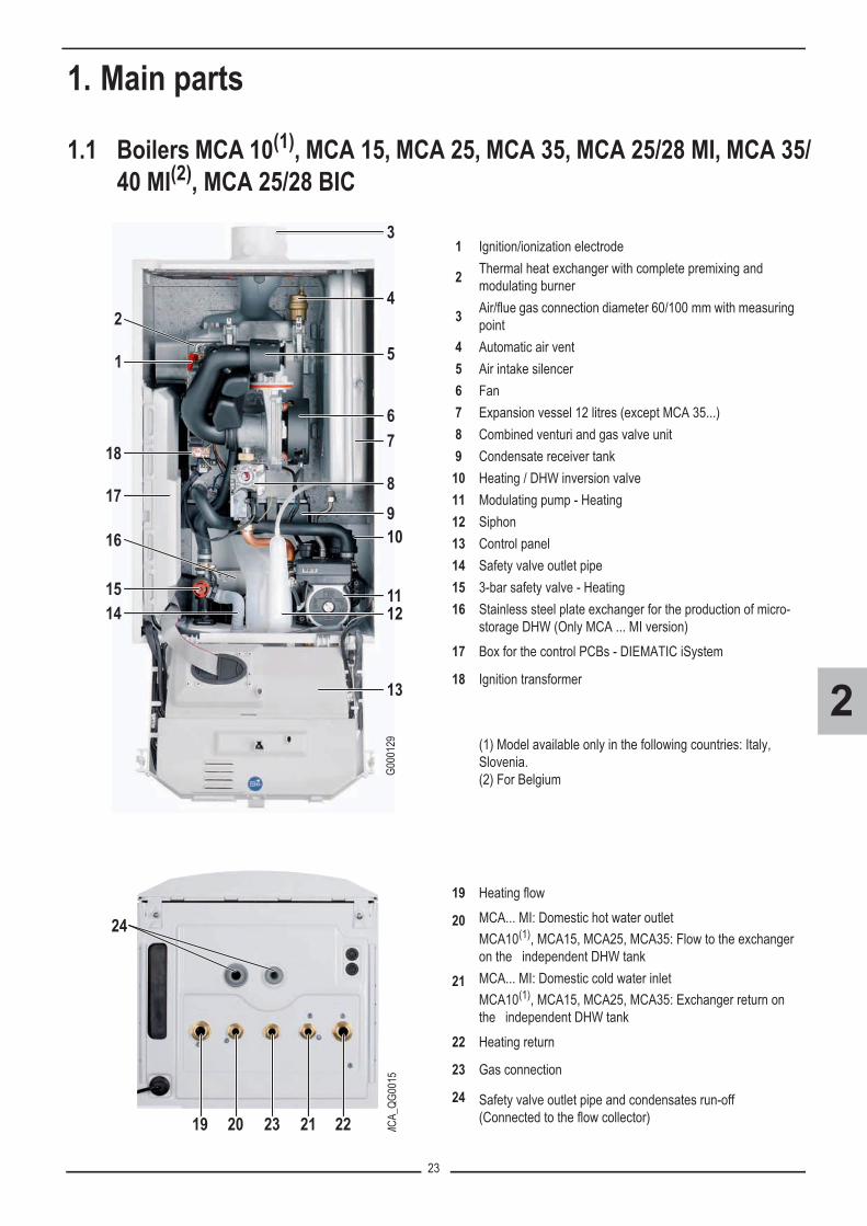
1.1 Boilers MCA 10(1), MCA 15, MCA 25, MCA 35, MCA 25/28 MI, MCA 35/40 MI(2), MCA 25/28 BIC
1 Ignition/ionization electrode
2 Thermal heat exchanger with complete premixing and modulating burner
3 Air/flue gas connection diameter 60/100 mm with measuring point
4 Automatic air vent5 Air intake silencer6 Fan7 Expansion vessel 12 litres (except MCA 35...)8 Combined venturi and gas valve unit9 Condensate receiver tank
10 Heating / DHW inversion valve11 Modulating pump - Heating12 Siphon13 Control panel14 Safety valve outlet pipe15 3-bar safety valve - Heating16 Stainless steel plate exchanger for the production of micro-
storage DHW (Only MCA ... MI version)17 Box for the control PCBs - DIEMATIC iSystem
18 Ignition transformer
(1) Model available only in the following countries: Italy, Slovenia.(2) For Belgium
19 Heating flow
20 MCA... MI: Domestic hot water outletMCA10(1), MCA15, MCA25, MCA35: Flow to the exchanger on the independent DHW tank
21 MCA... MI: Domestic cold water inletMCA10(1), MCA15, MCA25, MCA35: Exchanger return on the independent DHW tank
22 Heating return
23 Gas connection
24 Safety valve outlet pipe and condensates run-off (Connected to the flow collector)
1
1415
17
18
16
2
3
4
5
67
8910
1112
13
G000
129
24
19 20 23 21 22 MCA_
QG00
15
24
19 20 23 21 22 MCA_
QG00
15

24
2
1.2 Boiler MCA 25/28 BIC
Specific parts:25 Domestic expansion vessel
26 DHW calorifier comprising 3 interconnected stainless steel tanks
27 DHW load pump28 7-bar safety valve - Domestic hot water
19 Heating flow
20 Domestic hot water outlet
21 Domestic cold water inlet
22 Heating return
23 Gas connection
24 Safety valve outlet pipe and condensates run-off (Connected to the flow collector)
25
26
27
28
MCA_
QG00
08A
24
19 20 23 21 22 MCA_
QG00
15
24
19 20 23 21 22 MCA_
QG00
15

25
2
1.3 DIEMATIC iSystem control panel
The DIEMATIC iSystem control panel is an electronic regulator which can be programmed, and ensures the following functions:- Boiler temperature regulation via action on the modulating burner in accordance with the outside temperature and, where
applicable, the room temperature if a CDI4, CDR4 or simplified interactive remote control (optional) is connected,- Command and control of a direct circuit without mixing valve- Command and control of a first circuit with mixing valve, with the flow sensor option (Option package AD199),- Command and control of a second mixing valve circuit, with the PCB + flow sensor option (Option package AD249).
Nota: Each of these 3 heating circuits can be equipped with a CDI4, CDR4 or simplified FM52 remote control (Options).- Programming and priority control of a DHW circuit, with DHW sensor option (Package AD212),- Anti-freeze protection for the installation and the environment if the home is empty- 2 to 10 boilers can be connected in a cascade,- Option of connecting 1 to 10 DIEMATIC VM control systems- Management of systems combining various heating generators (boiler + heat pump or boiler + solar system…)
This allows the installer to set the parameters for the heating system as a whole.
� Refer to the specific after sales guide: DIEMATIC iSystem control panel.
Main ON/OFF switch

26
2
Description of the keys and the display
bar
STD
0 2 4 6 8 10 12 14 16 18 22 2420
AUTO
A
B
C
D E �
G
G00
0011
-A
I
�
A Temperature setting key (heating, DHW, swimming pool)
B Operating mode selection keyC DHW override keyD Key to access the parameters reserved for the installerE Keys on which the function varies as and when
selections are madeF Rotary setting button and push button:
���: Turn the rotary button to scroll through the menus or modify a value
���: Press the rotary button to access the menu selected or confirm a value modification
G A bar is displayed when a DHW override is activated:��Flashing bar: Temporary override��Steady bar: Permanent override
H Name of the circuit for which the parameters are displayed
I Timer programmes graphic display bar:��Dark area �: Heating period in comfort mode or DHW
production enabled or operation enabled periods.��Light area �: Heating period in reduced mode or DHW
production not enabled or not enabled operation periods.
Symbols�� Comfort mode: The symbol is displayed when a DAY
override (comfort) is activated��Flashing symbol: Temporary override��Steady symbol: Permanent override
� Reduced mode: The symbol is displayed when a NIGHT override (reduced) is activated��Flashing symbol: Temporary override��Steady symbol: Permanent override
� Holiday mode: The symbol is displayed when a HOLIDAY override (antifreeze) is activated��Flashing symbol: Holiday mode programmed��Steady symbol: Holiday mode active
� Manual mode� The symbol is displayed when domestic hot water
production is running� Valve indicator: The symbol is displayed when a 3-way
valve is connected�: Opening the 3-way valve: Closing the 3-way valve
The symbol is displayed when the pump is operating� Access to the various menus� Used to scroll through the menus Used to scroll through the parameters
� Used to display the curve of the parameter selected? The symbol is displayed when help is availableSTD Reset of all time programmes (Press for 5 sec.)�/� Comfort/reduced selection or selection of the days to
be programmed Back to the previous levelESC Back to the previous level without saving the
modifications made� Manual reset�� Arrows are displayed when lines are masked higher or
lower in the list. Both arrows flash when it is possible to modify a value.
�� Flame status� Pressure indicator: The symbol is displayed when a
water pressure sensor is connected��Flashing symbol: The quantity of water is insufficient��Steady symbol: The quantity of water is sufficient.
Water pressure level:�: 0,9 to 1,1 bar�: 1,2 to 1,5 bar�: 1,6 to 1,9 bar�: 2,0 to 2,3 bar�: > 2,4 bar
� Summer mode: Reheating the domestic hot water remains ensured
� WINTER mode: Heating and domestic hot waterworking
AUTO Operation in automatic mode according to the timerprogramme

27
2
2. Operating principle2.1 Operating principle diagram
MCA 10(1), MCA 15, MCA 25 MCA 351 Heat exchanger (Heating circuit)2 Heating flow
3 Primary flow to DHW tank (when DHW tank is connected)
4 Primary return, DHW tank (when DHW tank is connected)
5 Heating return6 Reversal valve7 Heating pump 8 Expansion vessel
(1) Model available only in the following countries: Italy, Slovenia.
MCA 25/28 MI MCA 35/40 MI(2)1 Heat exchanger (Heating circuit)2 Hydrobloc3 Plate heat exchanger4 Heating flow5 Domestic hot water outlet6 Domestic cold water inlet7 Heating return8 Reversal valve9 Heating pump
10 Expansion vessel
(2) Only for Belgium
MCA 25/28 BIC 1 Heat exchanger (Heating circuit)2 Hydrobloc3 Plate heat exchanger 4 Heating flow5 Domestic hot water outlet6 Domestic cold water inlet7 Heating return8 DHW pump9 Expansion vessel (DHW circuit)
10 Reversal valve11 Heating pump
12 DHW calorifier comprising 3 interconnected stainless steel tanks
13 Expansion vessel (Heating circuit)
T001884-C
1 8
7
6
2 3 4 5T002885-A
1
7
6
2 3 4 5
T001868-B
1
23
10
9
8
4 5 6 7T001874-A
1
23
9
8
4 5 6 7
1
23
11
10
12
13
8
9
4 5 6 7

28
2
2.2 Operating principle• CombustionThe casing fitted to the boiler is also used as an air box.Air is sucked in by the fan and gas injected into the venturi by the fan intake. The fan rotation speed is set according to the settingsparameters, the thermal energy requirement and the temperatures measured by the temperature sensors. The gas and air are mixed in the venturi. The gas/air ratio ensures that the quantities of gas and air are adjusted to each other.This provides optimum combustion on the entire output range. The gas/air mixture is fed into the burner on top of the exchanger.The mixture is ignited by the ignition/ionization combination electrode which also monitors the flame.The modulating burner heats the water flowing through the heat exchanger. When the combusted gas temperatures are lowerthan the dew point (approx. 55°C, the temperature as of which the steam in the combusted gases starts to condense), the steamin the combusted gases will condense in the lower part of the heat exchanger. The heat released during this condensation process(the latent heat or condensing heat) is also transferred to the heating water. The cooled combustion gases are evacuated via the combustion gas outlet flue. The condensation water is evacuated via asiphon.• Control systemThe boiler's DIEMATIC iSystem control panel guarantees a permanent heat supply adapted to needs. The boiler managesnegative influences from the environment (particularly an insufficient water flow rate and venting problems). In the presence ofsuch influences, the boiler doesn't switch into locking mode, but first reduces his power and, depending on the nature of thecircumstances, will be temporarily out of service (blocking or stop). The boiler continues to supply heat as long as safetyrestrictions allow.• Boiler regulation - Heating water regulationThe DIEMATIC iSystem control panel modulates boiler output between the minimum and maximum values based on the heatingflow temperature.The boiler is fitted with an electronic temperature regulator with a flow temperature sensor (boiler sensor) and a return temperaturesensor. The flow temperature can be set between 20°C and 90°C. The boiler reduces its power when the set outlet-temperatureis attained. The burner shutdown temperature is the heating flow temperature setting +5°C.
• SafetyThe boiler is protected against overheating by a safety thermostat (HLS) fitted to the heat exchanger. The safety thermostat shutsdown the boiler if the water temperature reaches 110°C.
�TMAX = BACK TEMP + 20 K
CALC.T. BOILER = Boiler temperature setting
• If the flow rate is too low �T�45 K or the heating flow temperature increases too quickly, the boiler is locked out for 10 minutes.
• When there is no water in the boiler or the pump is not running, the boiler goes into safety shutdown at �T��� K. The following message is displayed: DEP-RET>MAX (L11).
(�T = BOILER TEMP. - BACK TEMP)
ΔTMAX
CALC.T. BOILER
Boilertemperature
t
BOILER. T.
BACK TEMP
G00
0185

29
2
• Low flow rate safety device
The boiler is fitted with a low flow rate safety device, based on temperature measurements. By reducing its output when the waterflow rate is in danger of becoming insufficient, the boiler continues to operate as long as possible. If the flow rate is too low �T�45 K or the heating flow temperature increases too quickly, the boiler is locked out for 10 minutes.When there is no water in the boiler or the pump is not running, the boiler goes into safety shutdown at �T��� K. The followingmessage is displayed: DEP-RET>MAX (L11).
• Regulating the domestic hot water : MCA 10(1) - MCA 15 - MCA 25 - MCA 35On boilers without a plate exchanger, a reversal valve carries the heating water either to the heating circuit or to the primary circuitin the DHW tank. If domestic hot water reheating is required, the control panel switches the reversal valve to the DHW positionand engages the boiler pump.
• Regulating the domestic hot water : MCA 25/28 MI, MCA 35/40 MI(2)
On boilers used for heating and micro-acucmulated domestic hot water production, an integrated plate exchanger heats thedrinking water. A reversal valve is used to carry the heated water either to the heating system or to the plate exchanger. Aflowmeter signals that a hot water tap has been turned on. This signal is transmitted to the control panel, which then switches thereversal valve to the domestic hot water position and engages the boiler pump. The heating water reheats the domestic water in the plate exchanger. In comfort mode, if there is no hot water draw-off, the boilerhandles the periodic reheating of the plate exchanger. Any particles are kept out of the plate exchanger by a water filter.• Regulating the domestic hot water (MCA 25/28 BIC)An integrated plate exchanger handles domestic hot water production. A reversal valve is used to carry the heated water either tothe heating system or to the plate exchanger. A DHW sensor signals domestic hot water demands. This signal is transmitted tothe control panel, which then switches the reversal valve to the domestic hot water position and engages the DHW pump.The heating water reheats the domestic water in the plate exchanger. This water is pumped into the boiler tank to provide aconstant plentiful supply of domestic hot water. In comfort mode, if the domestic hot water is not drawn off, the boiler reheats the plate exchanger and the domestic hot water inthe tanks at regular intervals. Any particles are kept out of the plate exchanger by a water filter. • Burner operationIn heating mode, the burner operates for a minimum duration of 30 seconds.In DHW mode: no minimum burner operating duration.An anti-short burner cycle is active when the boiler temperature exceeds the burner regulation set point by 5°C (BURNERSETPOINT) . The anti-short cycle varies between 3 and 15 minutes, depending on the boiler temperatures and the set points.
(1) Model available only in the following countries: Italy, Slovenia.(2) Only for Belgium
MCA 10(1)... MCA 25
�p: Pressure dropQ: Water flow: Max = 1680 l/h
MCA 35
�p: Pressure dropQ: Water flow: Max = 2460 l/h
The boiler's modulating control system limits the maximum difference in temperature between the heating flow and return andthe maximum speed at which the flow temperature increases. In this way, the boiler does not require a minimum water flow rate.
T001978-A
0
100
200
300
400
500
600
700
0 5001037437
15001000 2000 2500
∆p [m
bar]
Q [l/h]623 830
∆T = 20K
10 kW15 kW
20 kW
25 kW
T001749-B
0
100
200
300
400
500
600
0 5001043 1252 1465835
15001000 2000 2500
∆p [m
bar]
Q [l/h]
∆T = 20K
20 kW25 kW
30 kW35 kW

30
2
2.3 Pump logic� Venting cycleWhen switching on or on restart after an fault generated by the PCU board (type Lxx), the control panel launches a 3-minuteventing cycle. The display shows M20 VENTING and the boiler temperature. During the venting phase, the boiler pump is running and switches alternately from the set min speed to the set maxspeed(Parameters: MIN.PUMP SPEED and MAX.PUMP SPEED).The boiler pump and the reversal valve are switched alternately until the end of the venting cycle.
� Boiler pumpThe modulating boiler pump runs whenever heating is required (Heating or DHW).Pump modulation: the pump speed is modulated to maintain a �T of 20 K between the flow and return temperature.The boiler pump shuts down in the following cases:- If there is no heating requirement (heating or DHW) after a post-operation time delay of 3 minutes (Factory setting, parameter
TIMER GENE P. in menu #PRIMARY INSTAL.P).- If an Lxx type fault occurs
� DHW pump (MCA 25/28 BIC)The DHW sensor (WS) triggers the request:- The DHW pump starts up whenever there is a draw-off or a DHW reheating requirement, or, at the latest, after a time delay of
20 seconds (when the boiler temperature is too low). - The burner and the boiler pump start up- The reversal valve switches to the DHW positionWhen the temperature measured by the DHW sensor (WS) reaches the DHW set point, the burner is shut down, the reversal valveswitches to the heating position and the boiler pump shuts down if there is no heating requirement. The DHW pump is shut downafter a time delay of 15 seconds. The DHW sensor (TS) located on the DHW pump outlet is used to regulate / adapt burner modulation to compensate for thevariations in temperature until the temperature setting is reached.

31
2
� Secondary pumps• Anti blocking of pumps:
In SUMMER mode, the pumps are run for 1 minute every Saturday at 24 hours to avoid their blocking.• Influence of the room temperature sensor(s):
Room temperature correction is activated if the influence of the room sensor is higher than 0 (Parameter INFL.ROOM S. in themenu #SECONDARY INSTAL.P, Factory setting: 3).Self-adaptivity is active if the following conditions are met:- If the parameter ADAPT in the menu #SECONDARY INSTAL.P is set to ON (Factory setting = ON)- If the influence of the room temperature sensor is higher than 0 (Parameter INFL.ROOM S. in the menu #SECONDARY
INSTAL.P, Factory setting: 3)- If the operating time in comfort mode is higher than 3 hours- If the average water temperature does not transgress any limits at the moment of adaptation.
• Without room sensor:There can be no correction of room temperature, autoadaptivity or room antifreeze protectionComfort mode: The pump continuously runs.Reduced mode:
1.If #FITTER PARAM. = LOW NIGHT: (reduced night temperature) Pumps are permanently switched on.2.If #FITTER PARAM. = NIGHT OFF: (shutdown at night) The pumps are off unless antifreeze is activated.
21,516,5
15,51620,5
20
G000217
ON
Roomtemp.
OFF ON ON OFF ON
Time Time
Set point
Set point
Time Time
°C
Roomtemp.
°C
Set point +1,5 K
Set point +0,5 K
Set point +0,5 K
Set point -0,5 K
Comfort mode Reduced mode

32
2
� SUMMER modeThe control unit integrates 2 different SUM/WIN functions:
• Summer mode selected used the MODE button: the symbol � is displayed.In SUMMER mode, the pumps are run for 1 minute every Saturday at 24 hours to avoid their blocking. The heating is off. DHWtank programme active. The installation's antifreeze protection remains active.
• Su: automatic “Summer“ cut-off: the symbol � is displayed.Two functions operate in parallel on the automatic shutdown:- Fast automatic SUM/WIN function: this takes 2 hours.- Slow automatic SUM/WIN function: this depends on the inertia of the building (10-50 hours)
In the following example: the switch to winter mode is made as the outside temperature has remained below the temperatureset point -1 K for 10 hours
.
Remarks:- To go back to heating mode, at least one circuit must be in demand. Take care to ensure that the room sensor is set
correctly.- Protecting the installation from frost
If the installation's antifreeze protection is requested: the pumps restart and the installation is heated so as to meet the variousminimum set points.
- If OFF has been selected in the SUM/WIN parameter, the automatic function is deactivated.
G00
0218
-04
222
t� 2 h 2 h 2 h 8 h
OutsideTemp.� C
Set point - 1 K
Time (h)
Switching toWINTER mode
Switching toSUMMER mode
Slow activation of SUMMER mode
10 h
4 6 8 10 12 14 16 18 20 22 24 26 28 30 32 34 36 38 40 42 44 46 48
19
25
Switching toSUMMER mode
Switching toWINTER mode
Example with SUM/WIN set point temperature = 22°C and I=0 i.e. 10 hours

33
3
PRODUCT DEVELOPMENT

34
3
Contents
1. History . . . . . . . . . . . . . . . . . . . . . . . . . . . . . . . . . . . . . . . . . . . . . . . . . . . . . . . . . . . . . . . . . . . . 351.1 Product launch date/ Modifications . . . . . . . . . . . . . . . . . . . . . . . . . . . . . . . . . . . . . . . . . . . . . . . . . . . . . . . . 351.2 Software versions . . . . . . . . . . . . . . . . . . . . . . . . . . . . . . . . . . . . . . . . . . . . . . . . . . . . . . . . . . . . . . . . . . . . . 35
2. Details of the modification . . . . . . . . . . . . . . . . . . . . . . . . . . . . . . . . . . . . . . . . . . . . . . . . . . . . 362.1 IT2549 (27/10/2009): New SCU EPROM software version . . . . . . . . . . . . . . . . . . . . . . . . . . . . . . . . . . . . . . 362.2 IT2554B (08/04/2010): Modification of the gas valve and of the pump . . . . . . . . . . . . . . . . . . . . . . . . . . . . . 39
2.2.1 Description of the modifications . . . . . . . . . . . . . . . . . . . . . . . . . . . . . . . . . . . . . . . . . . . . . . . . . . . . . . . . . . . . . . 392.2.2 Appliances concerned - Application date . . . . . . . . . . . . . . . . . . . . . . . . . . . . . . . . . . . . . . . . . . . . . . . . . . . . . . . 392.2.3 Spare parts . . . . . . . . . . . . . . . . . . . . . . . . . . . . . . . . . . . . . . . . . . . . . . . . . . . . . . . . . . . . . . . . . . . . . . . . . . . . . . 402.2.4 Gas settings . . . . . . . . . . . . . . . . . . . . . . . . . . . . . . . . . . . . . . . . . . . . . . . . . . . . . . . . . . . . . . . . . . . . . . . . . . . . . 41
2.3 IT2557A: New SCU EPROM software version . . . . . . . . . . . . . . . . . . . . . . . . . . . . . . . . . . . . . . . . . . . . . . . 42

35
3
1. History
1.1 Product launch date/ Modifications
(1) Model available only in the following countries: Italy, Slovenia.(2) Only for Belgium.
1.2 Software versions
Appliance Date Details
MCA 15 - MCA 25 - MCA 25/28 MIApril , 2009 On sale in FRANCEFrom: may/June 2009 Commercialization in other countries
MCA 35 - MCA 35/40 MI(2) November 2009 On sale in FRANCEFrom: February 2010 Commercialization in other countries
MCA 25/28 BICNovember 2009 On sale in FRANCEFrom: February 2010 Commercialization in other countries
MCA 10(1) November 2009 On sale in FRANCEFrom: may/June 2010 Commercialization in other countries
For all models except MCA 35 19/02/2010New pump, Class A - All countries except: Belgium, PolandApplied in factory from following serial number:1004908445480
For all models 19/02/2010New gas valve.Applied in factory from following serial number:1004908445480
Appliance Card Reference of the SCU PCB (mounted board)
Reference in spare parts Versions Application date
MCA 15-25MCA 25/28 MI Card SCU
121742 / 200014268 S101048
V1.1 21/04/2009(since lounching)
MCA 15-25MCA 25/28 MI Card SCU V1.2 15/09/2009
MCA 35 Card SCU V1.2 since lounchingMCA 25/28 BIC Card SCU V1.2 since lounchingFor all models Card SCU 123986 / 200014268 S101048 V1.5 30 June 2010

36
3
2. Details of the modification
2.1 IT2549 (27/10/2009): New SCU EPROM software version
The SCU PCB software version changes from V1.1 to V1.2
� Application in factory - Concerned PCB's
� The SCU PCB available in the Spare Part Centre under the reference S101048, are up to date since 15/09/2009.
� To check the SCU PCB software version� Display menu #MEASURES (Press the � key)� Turn the rotary button to display parameter CTRL� The software version is displayed : CTRL V...
or: check the label sticked on the SCU PCB:
Reference of the SCU PCB (mounted board) Reference in spare parts SCU programme
version Application date
121742 / 200014268 S101048 V1.2 15/09/2009
G000068 SCU PCB software versionSCU-board IOBL software version (not changed)

37
3
� Updating of the software version
• The updating of the SCU PCB software version is necessary in following cases:- Skipping of days on the display- False warning of following defects on the display: IOBL.3WV B DEF and IOBL.3WV C DEF
• The updating of the software version is made by using the programming tool.
� The programming tool allows the software version updating of the following control panels: - DIEMATIC iSystem (Boilers MCA....) - DIEMATIC-m3 (Boilers C 230, GT 330... ).
� Programming tool� Connector for the programming tool
�Refer to the instructions delivered with the package.
G000065A
TS + B AB
0-10V S AMB C
4 3 2 1 2 1+ -S AMB B
2 1S AMB A
2 1
S SYST + TA - S ECS S EXT S DEP C
2 12 12 12 1 2 1S DEP B
2 1
2
1
SCU

38
3
� Details of the modification - IT 2549
• Main modifications:- Corrected the skipping of days on the display- Corrected the problem of false warning on the display for following defects: IOBL.3WV B DEF and IOBL.3WV C DEF
• Modifications on the display:- In the menu #TEST INPUTS: addition of clock calibration on the display (CALIBRA.CLOCK). The parameter is only
displayed if INSTALLATION parameter is set to EXTENDED.- Addition of a vertical dotted line which means that a defect took place, on all the curves and not only on the curve
OUTLET TEMP. B.- Correction of several translations (for example, the translation of OUI / NON in French is YES / NO in English and JA /
NEIN in German)- In the menu #TEST INPUTS: addition on the display of boiler radio module (MC.VERSION) and outside radio-controlled
temperature sensor (OUTSI.S.VERSION) software versions.- Correction of the descriptive texts for parameters TOTAL RESET and RESET PROG (they were inverted).- Correction of the descriptive texts for parameters VER.ROM and VERS.PARAM.PCU (they were inverted).- When adjusting a parameter and when a defect appears, the regulator stays in the menu. Previously it went back on the
main display with the display of the defect.- At the boiler start up: Deleted the sensor defect display for not connected sensors.- Deleted the sensor defect display SYST.SENS.FAIL., when activating a cascade and pairing with a DIEMATIC VM, if
the system sensor is not connected.
• Modifications at the regulation level:- "The relative DHW-priority (parameter PRIORITY DHW set on SLIDING) is no more taken into account by circuit A when
it is configured in ""high temperature"" (parameter CIRC. A: set to H.TEMP)".- If parameter OUT.ANTIFREEZE is set to NO, the installation antifreeze protection is no longer ensured.- If parameter O.DHW: is set to RV, it is no more necessary to set parameter B.P. DELAY to 0 to avoid the time-delay to
start after a domestic hot water production.- In cascade, the calculated set-point temperature sent to the PCU is equal to the measured boiler temperature, minus 2 K
(and no more minus 0.2 K), if the boiler temperature is above the boiler set point temperature. It leaves more time for theboiler to modulate downwards, without stopping it.
- The 3-way valves B and C do not remain any more closed permanently between the tenth and the twentieth minute afterswitching on the boiler.
- When an IOBL (In One By Legrand) scenario switch sends an override to the control panel, it is now possible, from theDIEMATIC iSystem control panel to modify this overrideFor example:
- the scenario puts the boiler into DAY mode- on DIEMATIC iSystem control panel, an other operating mode can be choosen, for example automatic
mode.- In summer mode (�), if parameter O.DHW: is set to RV and if the installation antifreeze becomes active or a chimney
sweeping is in progress, the switchover valve doesn't stay in DHW position, but switches into heating position.

39
3
2.2 IT2554B (08/04/2010): Modification of the gas valve and of the pump
2.2.1 Description of the modifications
� Gas valveTo allow better air / gas ratio setting and control, for all gas types, the whole INNOVENS MCA boiler range has been equippedwith a new gas valve. From now on, a diaphragm is only necessary for operation with propane, for boilers up to 28 kW.The new gas valve replaces the previous gas valve in spare parts.The settings, depending on the gas type, are modified (see below).
� PumpSome boiler models (see table below), have also been fitted with a new, high energy performance Class A pump. The previous pump and the new pump are interchangeable and remain available in spare parts.
2.2.2 Appliances concerned - Application date
* Belgium, Poland, Switzerland, Austria, Luxemburg
(1) Model available only in the following countries: Italy, Slovenia.(2) Current version available as soon as the stock of previous versions (which are not convertible to propane) will be sold out.
For propane version: Consult us.
Countryside Appliance Package no. Article no. New pumpApplied in factory from
following serial number
Application date
All countries except (*)
MCA 10(1) HR2 100013601 yes
1004908445480 19/02/2010
MCA 15 HR3 100013602 yesMCA 25 HR4 100013603 yes
MCA 35(2) HR5 100013604 noMCA 25/28 MI HR1 100013600 yes
MCA 25/28 BIC HR6 100013605 yes
Belgium
MCA 15 BE HR9 100013608 noMCA 25 BE HR10 100013609 no
MCA 35 BE HR11100013610
or90621
no
MCA 25/28 MI BE HR7 100013606 no
Poland
MCA 15 PL HR14 100013613 noMCA 25 PL HR15 100013614 noMCA 35 PL HR16 100013615 no
MCA 25/28 MI PL HR13 100013612 noMCA 25/28 BIC PL HR17 100013616 no

40
3
2.2.3 Spare parts
(1) Model available only in the following countries: Italy, Slovenia.* All models
Previous version New versionMarkers Reference Description Markers Reference Description
Pump Pump: boiler models fitted with the Class A pump
2003 S100812Pump UPERO 15-60MCA 10(1) - MCA 15 - MCA 25MCA 25 / 28 MI,
2003 S100703Pump Grundfos UPM 15-70 RES Class AMCA 10(1) - MCA 15 - MCA 25MCA 25 / 28 MI, MCA 25/28 BIC
2003 S101187 Pump UPERO 15-70MCA 35 Pump: boiler models not fitted with the Class A pump
Gas valve 2003 S100812Pump UPERO 15-60MCA 15 BE/PL - MCA 25 BE/PLMCA 25/28 MI BE/PL, PL3001 S100887 Gas valve
Diaphragm 2003 S101187 Pump UPERO 15-70MCA 35 - MCA 35 BE - MCA 35 PL
3009 S101262 Propane diaphragm 2.85 mmMCA 10(1) - MCA 15 Gas valve
3009 S101263 Propane diaphragm 3.80 mm MCA 25, MCA 25 / 28 MI, 3001 S101507 Gas valve*
3009 S101256 Gas diaphragm H 3.7 mm MCA 10(1) - MCA 15 Diaphragm
3009 S101257 Gas diaphragm H 4.95 mm MCA 25, MCA 25 / 28 MI, 3009 S101541 Propane diaphragm 3.00 mm
MCA 10(1) - MCA 15*
3009 S101400 Gas diaphragm H 6.45 mm MCA 35 3009 S101542 Propane diaphragm 4.00 mm
MCA 25*, MCA 25 / 28 MI*, *
3009 S101245 Gas diaphragm L 4.4 mm MCA 15 MCA 35*: no diaphragm.
For gas H or L: no diaphragm.Propane air (For Italy): no diaphragm.Gas Lw, Gas Ls (For Poland): no diaphragm.
3009 S100883 Gas diaphragm L 5.80 mmMCA 25, MCA 25 / 28 MI,
3009 S101269 Gas diaphragm L 5.4 mm MCA 35
G000097 T001943-A
3009
3001
G000096_T001942-A
2003

41
3
2.2.4 Gas settings
� For operation with propane - MCA 10(1)- MCA 15 (BE/PL) - MCA 25/28 MI / BIC (BE/PL)For operation with propane: Fit the diaphragm for propane into the gas valve.Changing gas: Refer to the instruction booklets provided in the conversion kits.
� Setting the air/gas ratio - Full load / Part load (with new gas valve version)
� Setting procedure: See section 6, chapter 8.2
� O2/CO2 checking and setting value (with new gas valve version)
� See section 6, chapter 8.3
� Fan speeds depending on the gas usedThe settings of the fan speed depending on the gas type were not changed (Parameters: MIN.VENT., MAX.VENT.BOIL, MAX.VENT.DHW, START SP.).
� Setting values: See section 6, chapter 10
(1) Model available only in the following countries: Italy, Slovenia.

42
3
2.3 IT2557A: New SCU EPROM software version The SCU PCB software version changes from V1.2 to V1.5Details of the modification:- Parameter BS60 added in menu #SYSTEM (Possible setting: YES/NO, Factory setting: NO)
Allows to add the BS60 DHW calorifier to the hot water regulation, to allow a quicker heating of this calorifier.
� The parameter is displayed only under the following conditions: - if the INSTALLATION parameter is set to EXTENDEDand- if the software version of the boiler PCU card is version 1.4 or later.
To check the PCU PCB software version: � Set the parameter INSTALLATION to EXTENDED,� In the menu #TEST INPUTS, display the parameter VER.ROM.
- Correction of the "screed drying" algorithm: from now on, any second or further programmed screed drying, will functioncorrectly.
- Message display throughout the anti-short cycle. When the burner stops, the anti-short cycle prevents the burner from restartingtoo quickly. During this period, no message was displayed. Now, from version 1.5, the question mark "?" flashes and if the "?"key is pressed, the following message is displayed:"Operation assured when the restart temperature will be reached."
- If an external gas valve is connected on one of the terminal blocks marked AUX (on the PCB option AD249 for mixing valve)or A (on the SCU-board), and one of parameters S.AUX or O.PUMP A in the #SYSTEM menu is set on ORDER BURNER:the SCU-board will actually take into account all burner requests (coming from SCU-board and PCU-board) and no more onlythe ones coming from the SCU-board (heating requests).
- When in summer mode, the heating circuit pumps don't start systematically anymore, when the boiler is switched on.- Parameter SEQUENCE added (control system sequence) in #MEASURES menu, where it is more directly accessible.
� The parameter SEQUENCE is present also in the #TEST INPUTS menu.- Parameter BURNER SETPOINT added in the menu #PARAMETERS: corresponds to the effective set point calculated and
taken into account by the PCU. This set point should be equal to CALC.T. BOILER in steady-state operation. If this is not thecase, check the installation.
- Correction of several translations (NL,...)- Improved the TAS anode control, whereby the D38 TA-S DISCONNEC defect, no more appears unnecessarily (in particular
with BS60 calorifier).
43
4
TROUBLESHOOTINGDIAGRAMS

44
4
Contents1. Messages / Faults . . . . . . . . . . . . . . . . . . . . . . . . . . . . . . . . . . . . . . . . . . . . . . . . . . . . . . . . . . . 45
1.1 Troubleshooting . . . . . . . . . . . . . . . . . . . . . . . . . . . . . . . . . . . . . . . . . . . . . . . . . . . . . . . . . . . . . . . . . . . . . . . 451.2 "SAV" level of the DIEMATIC iSystem control system . . . . . . . . . . . . . . . . . . . . . . . . . . . . . . . . . . . . . . . . . 451.3 Messages: Bxx or Mxx . . . . . . . . . . . . . . . . . . . . . . . . . . . . . . . . . . . . . . . . . . . . . . . . . . . . . . . . . . . . . . . . . . 451.4 History . . . . . . . . . . . . . . . . . . . . . . . . . . . . . . . . . . . . . . . . . . . . . . . . . . . . . . . . . . . . . . . . . . . . . . . . . . . . . . 46
2. Diagrams . . . . . . . . . . . . . . . . . . . . . . . . . . . . . . . . . . . . . . . . . . . . . . . . . . . . . . . . . . . . . . . . . . 472.1 B00, B08, B09: Parameter error . . . . . . . . . . . . . . . . . . . . . . . . . . . . . . . . . . . . . . . . . . . . . . . . . . . . . . . . . . 482.2 L00: PSU fault . . . . . . . . . . . . . . . . . . . . . . . . . . . . . . . . . . . . . . . . . . . . . . . . . . . . . . . . . . . . . . . . . . . . . . . . 492.3 L01: Parameters are not correct . . . . . . . . . . . . . . . . . . . . . . . . . . . . . . . . . . . . . . . . . . . . . . . . . . . . . . . . . . 502.4 L02, L03, L04 ,L06, L07, L08 : Flow sensor or boiler return sensor fault . . . . . . . . . . . . . . . . . . . . . . . . . . . 512.5 L05, L09 - Temperature too high . . . . . . . . . . . . . . . . . . . . . . . . . . . . . . . . . . . . . . . . . . . . . . . . . . . . . . . . . . 522.6 L10, L11: Fault of the difference between flow and return temperature . . . . . . . . . . . . . . . . . . . . . . . . . . . . 532.7 L12: Maximum boiler temperature exceeded . . . . . . . . . . . . . . . . . . . . . . . . . . . . . . . . . . . . . . . . . . . . . . . . 542.8 L14: Igniter fault . . . . . . . . . . . . . . . . . . . . . . . . . . . . . . . . . . . . . . . . . . . . . . . . . . . . . . . . . . . . . . . . . . . . . . . 552.9 L16: Parasite flame . . . . . . . . . . . . . . . . . . . . . . . . . . . . . . . . . . . . . . . . . . . . . . . . . . . . . . . . . . . . . . . . . . . . 562.10 L17: Problem of the Gas valve control . . . . . . . . . . . . . . . . . . . . . . . . . . . . . . . . . . . . . . . . . . . . . . . . . . . . . 572.11 L34: Fan fault . . . . . . . . . . . . . . . . . . . . . . . . . . . . . . . . . . . . . . . . . . . . . . . . . . . . . . . . . . . . . . . . . . . . . . . . 582.12 L35: Connection or outlet and return sensor reversed . . . . . . . . . . . . . . . . . . . . . . . . . . . . . . . . . . . . . . . . 592.13 L36: Ionization fault during operation . . . . . . . . . . . . . . . . . . . . . . . . . . . . . . . . . . . . . . . . . . . . . . . . . . . . . . 602.14 L37: SU PCB . . . . . . . . . . . . . . . . . . . . . . . . . . . . . . . . . . . . . . . . . . . . . . . . . . . . . . . . . . . . . . . . . . . . . . . . 612.15 L38: PCU PCB . . . . . . . . . . . . . . . . . . . . . . . . . . . . . . . . . . . . . . . . . . . . . . . . . . . . . . . . . . . . . . . . . . . . . . . 622.16 L39: The contact inlet BL is open . . . . . . . . . . . . . . . . . . . . . . . . . . . . . . . . . . . . . . . . . . . . . . . . . . . . . . . . 632.17 L40 . . . . . . . . . . . . . . . . . . . . . . . . . . . . . . . . . . . . . . . . . . . . . . . . . . . . . . . . . . . . . . . . . . . . . . . . . . . . . . . . 642.18 L250: The water pressure is too low . . . . . . . . . . . . . . . . . . . . . . . . . . . . . . . . . . . . . . . . . . . . . . . . . . . . . . 652.19 L251: Pressure gauge fault (Pressure sensor) . . . . . . . . . . . . . . . . . . . . . . . . . . . . . . . . . . . . . . . . . . . . . . 662.20 D03, D04, D05, D07, D09, D16 or D17: Sensor errors . . . . . . . . . . . . . . . . . . . . . . . . . . . . . . . . . . . . . . . . 672.21 D11, D12 or D13: Room sensor errors . . . . . . . . . . . . . . . . . . . . . . . . . . . . . . . . . . . . . . . . . . . . . . . . . . . . 682.22 D14: Communication with the boiler radio module (AD252) . . . . . . . . . . . . . . . . . . . . . . . . . . . . . . . . . . . . 692.23 D27 or B13: Communication fault . . . . . . . . . . . . . . . . . . . . . . . . . . . . . . . . . . . . . . . . . . . . . . . . . . . . . . . . 702.24 D29 or D30 . . . . . . . . . . . . . . . . . . . . . . . . . . . . . . . . . . . . . . . . . . . . . . . . . . . . . . . . . . . . . . . . . . . . . . . . . 712.25 D31 . . . . . . . . . . . . . . . . . . . . . . . . . . . . . . . . . . . . . . . . . . . . . . . . . . . . . . . . . . . . . . . . . . . . . . . . . . . . . . . 712.26 D32 . . . . . . . . . . . . . . . . . . . . . . . . . . . . . . . . . . . . . . . . . . . . . . . . . . . . . . . . . . . . . . . . . . . . . . . . . . . . . . . 722.27 D37 . . . . . . . . . . . . . . . . . . . . . . . . . . . . . . . . . . . . . . . . . . . . . . . . . . . . . . . . . . . . . . . . . . . . . . . . . . . . . . . 732.28 D38 . . . . . . . . . . . . . . . . . . . . . . . . . . . . . . . . . . . . . . . . . . . . . . . . . . . . . . . . . . . . . . . . . . . . . . . . . . . . . . . 74

45
4
1. Messages / Faults
1.1 TroubleshootingIn the case of failure, the control panel displays a message and a corresponding code.
� Switch the boiler off and switch back on. If the fault is no longer displayed: Check and ensure that the sensor and 230 Vcables are separated.
� If the message is not cleared: Correct the malfunction of the appliance.� Press the � button to clear the message or fault. The boiler starts up again automatically when the reason for the blocking
has been removed.
1.2 "SAV" level of the DIEMATIC iSystem control system� Access the "After Sales" level: Press key � for 10 seconds.
The menu #PARAMETERS is used to read the values when running and not running regarding the boiler and the variouscomponents connected.The #TEST OUTPUTS page supplies power to the outputs independently one by one to check that they are operating (pumps, 3-way valve, telephone relay.) The menu #TEST INPUTS is used to display the operating sequences and miscellaneous information...
� Refer to the specific after sales guide: DIEMATIC iSystem
1.3 Messages: Bxx or Mxx For the messages, code B00, B08 and B09: See following chapter " 2.1 B00, B08, B09: Parameter error" For the message, code B13: See following chapter " 2.23 D27 or B13: Communication fault"
For the other messages: Refer to the specific after sales guide: DIEMATIC iSystem

46
4
1.4 History� Access the "After Sales" level:Press key � for 10 seconds.� The menu #PARAMETERS is displayed� Select the menu #DEFAULT HISTORIC or Select the menu #MESSAGE HISTORIC
The menu #MESSAGE HISTORIC is used to consult the last 10 messages displayed by the control panel.The menu #DEFAULT HISTORIC is used to consult the last 10 faults displayed by the control panel.
� Refer to the specific after sales guide: DIEMATIC iSystem
bar
1
1
2
2
��
STD� � �
�
0 2 4 6 8 10 12 14 16 18 22 2420
�� AUTO� � � �
SUNDAY 11:45
10"C002483-A-04
TEMP.: 68°bar
1
1
2
2
��
STD� � �
�
0 2 4 6 8 10 12 14 16 18 22 2420
�� AUTO� � ����
#PARAMETERS#DEFAULT HISTORIC #MESSAGE HISTORIC#TEST OUTPUTS#TEST INPUTS
C002314-C-04

47
4
2. Diagrams
� Fault or message display:B...: Blocking messageM...: MessageL...: Fault generated on the PCU PCBD...: Fault generated on the SCU PCB.
� PCU, SU, SCU PCBs:The PCU, SCU and SU PCBs each include a light emitting diode (LED):- Green LED: normal operation, - Blinking LED: fault detected by the board on which the LED is flashing or defective PCB- LED off: the PCB is not powered electrically or is faulty.
� Used symbols
�
Before repair work:- Check that the fuses are in good working condition- Ensure that all connectors are engaged, that there are no loose wires, by pulling them gently,
nor any trapped or damaged wires.
Before and after each intervention : - Press the � key to clear the fault,- Check and ensure that the sensor and 230 V cables are separated.
Fault displayXXX FAULT
END
Check to be made (yes/no)
Processing to be carried out or comment
End of processing

48
4
2.1 B00, B08, B09: Parameter error
� Before and after each intervention, press the � key to clear the message or fault.
B00 - BL.PSU ERROR: The PSU PCB is incorrectly configuredB08 - BL.RL OPEN: The RL inlet on the PCU PCB terminal block is openB09 - BL.INV. L/N: Configuration error
END
noOK ?
yes
Reconfigure the boiler type:��Access the "After Sales" level��Select the menu #CONFIGURATION��Select the parameter TYPE and choose another type of boiler.
Validate by pressing the rotary setting button.��Set the parameter TYPE to the correct boiler type and confirm.��Carry out the specific settings of the parameters again in the
menus #PRIMARY LIMITS and #PRIMARY INSTAL.P (Allparameter settings in these menus are replaced by their factorysetting).
Replace PSU PCB.

49
4
2.2 L00: PSU fault
� Before and after each intervention, press the � key to clear the message or fault.
L00 - PSU FAIL : PSU PCB not connected or faulty.
Bad connection:- Check the wiring between the PCU and PSU PCBs - Check that the SU PCB has been correctly put in place on the
PCU PCB (The SU board communicates with the PCU board)
Connection OK?
yes
Replace the harness
Change the SU PCB
END
no
noOK ?
yes
Change the PSU PCB.
no
OK ?yes
Clear the fault by pressing the �button.

50
4
2.3 L01: Parameters are not correct
� Before and after each intervention, press the � key to clear the message or fault.
L01: PSU PARAM FAIL: The safety parameters are incorrect
Change the PSU PCB.
END
Clear the fault by pressing the � button
OK ?yes
no

51
4
2.4 L02, L03, L04 ,L06, L07, L08 : Flow sensor or boiler return sensorfault
� Before and after each intervention, press the � key to clear the message or fault.
Check the ohmic value of the sensor on the X10 terminal block after removing the SU board (This allows also to check the harness)
(See section 6, chapter 6.2.4)
L02 - DEF.OUTLET S.: The boiler flow sensor has short-circuited (150 °C)L03 - DEF.OUTLET S.: The boiler flow sensor is on an open circuit (-40 °C)L04 - DEF.OUTLET S.: Boiler temp too low (-40 °C)L06 - BACK S.FAILURE: The return temperature sensor has short-circuited (150 °C)L07 - BACK S.FAILURE: The return temperature sensor is on an open circuit (-40 °C)L08 - BACK S.FAILURE: Return temperature too low (-40 °C)
Check the Ohmic value of the sensor(See section 6, chapter 6.2.4)
Ohmic value OK ?
yes
yes
Ohmic value OK ?
Change the sensor
Replace the harness
END
no
no
Change the SU board fitted to the PCU PCB
Preliminary checks to be carried out:��Check whether the water circulation is correct (Heating
pump, Circulation, Pressure, Bleed...)��Carry out a visual check on the wiring and the sensor
connections.

52
4
2.5 L05, L09 - Temperature too high
� Before and after each intervention, press the � key to clear the message or fault.
L05 - STB OUTLET: Boiler temperature too high (110 °C)L09 - STB BACK: Return temperature too high (110 °C)
Power supply and modulation OK?
Check the water circulation direction in the boiler.
Hydraulic circuit OK?
Check the boiler pump.
END
no
yes
Preliminary checks to be carried out:��Check whether the water circulation is
correct (Heating pump, Circulation,Pressure, Bleed...)
��Check the cleanliness of the heatexchanger (sludging)
��Carry out a visual check on the wiring andthe sensor connections.
no Rectify the hydraulic circuit.
yes
Check the ohmic value of the sensor on the X10 terminal block after removing the SU board (This allows also to check the harness)
(See section 6, chapter 6.2.4).
Check the power supply to and the modulation of the pump(See section 6, chapter 6.7).
Ohmic value OK ?
Change the SU board fitted to the PCU PCB.
Replace the harness.
no
yes
OK ?
Replace the boiler pump.
yesTemperature displayed matches actual temperature?
yes
no
Check the boiler's input.
no

53
4
2.6 L10, L11: Fault of the difference between flow and returntemperature
� Before and after each intervention, press the � key to clear the message or fault.
Change the sensor.
��Check the connection of the flow and return sensors: - X114 connector on the return sensor- Connector X115 on the flow sensor.
Check the ohmic value of the flow and return sensors.
L10 - DEP-RET<MIN: Difference between the flow and return temperatures insufficient
L11 - DEP-RET>MAX: Difference between the flow and return temperatures too great
Preliminary checks to be carried out:��Check whether the water circulation is
correct (Heating pump, Circulation,Pressure, Bleed...)
��Check the cleanliness of the heatexchanger (sludging)
��Carry out a visual check on the wiring andthe sensor connections.
Check the power supply to and the modulation of the pump(See section 6, chapter 6.7).
Power supply and modulation OK?
Check the water circulation direction in the boiler.
Hydraulic circuit OK?
no
yes
no Rectify the hydraulic circuit.
yes
yes
Ohmic value OK ? no
OK ?
END
Check the ohmic value of the sensor on the X10 terminal block after removing the SU board (This allows also to check the
harness) (See section 6, chapter 6.2.4).
yes
Ohmic value OK ? Replace the harness.no
Change the SU board fitted to the PCU PCB.
Check the connection.no
yes
Check the boiler pump.
yes OK ?
Replace the boiler pump.
no
Change the SU board fitted to the PCU PCB.

54
4
2.7 L12: Maximum boiler temperature exceeded
� Before and after each intervention, press the � key to clear the message or fault.
L12: STB OPEN:Maximum boiler temperature exceeded
Preliminary checks to be carried out:��Check whether the water circulation is
correct (Heating pump, Circulation,Bleed...)
��Check the cleanliness of the heatexchanger (sludging)
��Carry out a visual check on the wiring andthe sensor connections.
Check the ohmic value of the safety thermostat(See section 6, chapter 6.11).
yes
Ohmic value of between 0 and 1
Ohm?Replace the safety thermostat.no
Check the connection or Replace the harness.
Safety thermostat connection OK? no
END
Change the SU board fitted to the PCU PCB.
Check that the SU PCB has been correctly put in place on the PCU PCB.
OK ?Put the SU board back
in place on the PCU board.
yes
no
yes

55
4
2.8 L14: Igniter fault
� Before and after each intervention, press the � key to clear the message or fault.
OK ?
OK ?
OK ?
Check the ignition transformer: See section 6, chapter 6.3.
SU defective. Replace it.
Check the wiring.
Replace the harness.
Replace the ignition
transformer.
Replace the electrode.
yes
PCU defective. Replace it.
yes
END
Replace the gas valve.
Check the drop in pressure upstream when opening the gas valve (See section 5, chapter 8.1.).
- Check the setting of the CO2ratio and the fan rotation speed for the type of gas used: See section 6, chapter 6.10- Check fouling on the burner.
Flame stable and well formed ?
Checking the ignition electrodeSee section 6, chapter 6.3.
L14: BURNER FAILURE5 unsuccessful start-up attempts
Presence of ignition arc ?
Flame present ?
Ionization current<3 to 9 µA> ?
OK ?
yes
no
no
no
yes
no
no
yes
yes
yes
no
no
yes
yes
no
Preliminary checks to be carried out:��Check that the gas valve is fully opened��Check that the gas supply pressure is present��Check that the gas pipe has been sufficiently vented��Check that the air/flue gas pipe is not blocked and has no
leaks��Check that the siphon has been filled and is not blocked��Check that there is no recirculation of combusted gases
inside or outside the boiler.
OK ?
Check the coil on the gas valveSee section 6, chapter 6.4.
yes
noEND
OK ?
noChecking the ignition
electrodeSee section 6, chapter
6.3.
Replace the electrode.no
OK ?yes
END

56
4
2.9 L16: Parasite flame
� Before and after each intervention, press the � key to clear the message or fault.
END
Switch the boiler off.
Check through the inspection hole whether there are any burner fibres or filaments in
contact with the electrodes.
L16: PARASIT FLAMEDetection of a parasite flame
Flame present ?
Flame still present ?
yes
no
no
yes
Carry out the cleaning
yes
Is this the case?
no
Check that the SU PCB has been correctly put in place on the PCU PCB.
OK ?Put the SU board
back in place on the PCU board.
yes
no
The burner continues to be incandescent owing to too high a CO2 percentage:
Set the CO2.
OK ?
Check the ignition transformer: See section 6, chapter 6.3.
Replace the ignition transformer.
yes
no
OK ?
Check the wiring.
Replace the harness.
yes
no
SU defective. Replace it.
OK ?
PCU defective. Replace it.
no
yes
OK ? Replace the electrode
yes
Checking the ignition electrodeSee section 6, chapter 6.3
no
� Isolate the gas supply.
� Replace the gas valve.

57
4
2.10 L17: Problem of the Gas valve control
� Before and after each intervention, press the � key to clear the message or fault.
Change the SU PCB.
END
L17: VALVE FAIL
no
Switch the boiler off and switch back on.Press the � key to clear the fault.
OK ? yes

58
4
2.11 L34: Fan fault
� Before and after each intervention, press the � key to clear the message or fault.
L34: FAN FAILUREThe fan is not running at the right speed.
yesyes
no
Change the PCU PCB.
Compare the display of the fan speed (SPEED FAN) and the fan set point (SETPOINT FAN) in the menu #PARAMETERS.
Set point = 0 and the fan is running.
Check the fan wiring.
Set point > 0 and Fan OFF.
Check the voltage on terminals 1 and 5 on the X91 connector (See section 6, chapter 6.10).
Set point > 0 and SPEED FANdifferent from
SETPOINT FAN.
yes
no
OK ?
no
yes
Replace the harness.
Clean the silencer and the fan (See section 6, chapter 4.11).
Check the fanSee section 6, chapter 6.10.
OK ?
no
yes
OK ?
no
yes
Replace the fan.
OK ?
no
yes
Voltage equal to approximately 28
V?
no
yes
Check the fan wiring.
OK ?no
yes
Replace the harness.
END
END

59
4
2.12 L35: Connection or outlet and return sensor reversed
� Before and after each intervention, press the � key to clear the message or fault.
Change the SU PCB.
END
Check the connection orReplace the harness.
L35: BACK>BOIL FAILFlow and return reversed.
Connections:OK ?
no
yes
noOK ?
Replace the defective sensor.
yes
Check the ohmic values of the boiler sensor and the return sensorSee section 6, chapter 6.2.
Check whether the boiler and return sensors have been correctly fittedSee section 6, chapter 6.2.
Preliminary checks to be carried out:��Check whether the water circulation is correct
(Heating pump, Circulation, Pressure, Bleed...)��Check the cleanliness of the heat exchanger
(sludging)��Carry out a visual check on the wiring and the
sensor connections.

60
4
2.13 L36: Ionization fault during operation
� Before and after each intervention, press the � key to clear the message or fault.
END
Make the correct CO2 settingSee section 6, chapter 8-9 (According to the type of gas valve).
L36: I-CURRENT FAILThe flame went out more than 5 times in 24 hours while the burner was operating.
Gas/air setting : OK ? no
yes
Preliminary checks to be carried out:��Check that the gas valve is fully opened��Check that the gas supply pressure is present��Check that the gas pipe has been sufficiently vented��Check that the air/flue gas pipe is not blocked and has no leaks��Check that the siphon has been filled and is not blocked��Check that there is no recirculation of combusted gases inside or
outside the boiler.
OK ?
OK ?
OK ?
Check the ignition transformer:See section 6, chapter 6.3.
Change the SU PCB.
Check the wiring.
Replace the electrode.
yes
OK ?
Change the PCU PCB.
yes
Checking the ignition electrodeSee section 6, chapter 6.3.
yes
no
no
no
yes
no
Replace the gas valve.
Check the drop in pressure upstream when opening the gas valveSee section 5, chapter 8.1.
OK ?noOK ? Check the coil on the gas valve See section 6, chapter 6.4
yes
no
yes
Replace the ignition transformer.
Replace the harness.

61
4
2.14 L37: SU PCB
� Before and after each intervention, press the � key to clear the message or fault.
L37: SU COM.FAIL : Communication failure with the SU PCB
Change the SU PCB.
END
no
Check that the SU PCB has been correctly put in place on the PCU PCB.
OK ?Put the SU board back in place on the PCU board.
yes

62
4
2.15 L38: PCU PCB
� Before and after each intervention, press the � key to clear the message or fault.
Run an AUTODETECTION in the menu #CONFIGURATION.
END
noOK ?
Check the connection orReplace the harness.
yes
no
OK ? yes
Change the PCU PCB.
L38: PCU COM.FAIL : Communication failure between the PCU andSCU PCBs.
Check the wiring between the PCU and SCU PCBs.
OK ?
Change the SCU* PCB.
yes
no
* If replacing the SCU PCB: redo the pairing of the IOBL peripherals if necessary.

63
4
2.16 L39: The contact inlet BL is open
� Before and after each intervention, press the � key to clear the message or fault.
L39: BL OPEN FAIL :The BL inlet opened for a short time.
The component or component harness connected to IN.BL is defective: Check / Replace.
END
no
��Check the device connected to the BL contact.If it is a flue gas thermostat: check the chimney,clean the heat exchanger.
��Check the setting of the parameter IN.BL in themenu #PRIMARY INSTAL.P.
��Press the � key to clear the fault.
yes
no
yesyes
Measure the ohmic value on the flue gas thermostat connector.
Replace the flue gas thermostat.
IN.BL used? no
yes
Fit the bridge to the BL input on the PCU board.
Fault still present ?
Fault still present ?
Change the PCU PCB.
no
��Fit the bridge to the BL input on the PCU board (Seesection 6, chapter 6.12)
��Press the � key to clear the fault.
Ohmic value equal to approximately 63 Ohm
?
noyes
Flue gas thermostat connected to IN.BL?

64
4
2.17 L40
� Before and after each intervention, press the � key to clear the message or fault.
L40: TEST.HRU.FAIL :HRU/URC unit test error.
END
no
��Switch the boiler off and switch back on.��Clear the fault by pressing the �
button.
OK ?
Run an AUTODETECTION in the menu #CONFIGURATION("After Sales" level).
no
OK ? yes
yes
Reconfigure the boiler type:��Access the "After Sales" level��Select the menu #CONFIGURATION��Select the parameter TYPE and choose another type of boiler.
Validate by pressing the rotary setting button.��Set the parameter TYPE to the correct boiler type and confirm.��Carry out the specific settings of the parameters again in the
menus #PRIMARY LIMITS and #PRIMARY INSTAL.P (Allparameter settings in these menus are replaced by theirfactory setting).

65
4
2.18 L250: The water pressure is too low
� Before and after each intervention, press the � key to clear the message or fault.
L250: DEF.WATER MIS.Water pressure too low.
Check the pressure sensorSee section 6, chapter 6.9.
END
no
Check the hydraulic circuit on the installation: check whether the actual water pressure is higher than 0.8 bar.
OK ?Rectify the hydraulic
circuit.
yes
noOK ?
yes
Replace the pressure sensor.
Preliminary checks to be carried out:��Check whether the water circulation is
correct (Boiler pump, Circulation,...)��Vent the heating installation.
Replace the PCU PCB.
� During the venting phase (display: DISGAS M20), if the pressure isinsufficient (less than 0.8 bar), the fault DEF WATER MISSING (code L250)is displayed.
� Press the � key to clear the fault. The boiler restarts. During operation, ifa lack of pressure occurs, the bar symbol flashes but no fault is displayed.

66
4
2.19 L251: Pressure gauge fault (Pressure sensor)
� Before and after each intervention, press the � key to clear the message or fault.
L251: MANOMETRE FAIL
Check the pressure sensorSee section 6, chapter 6.9.
END
no
Check the wiring.
OK ?Check the connection or
Replace the harness.
yes
noOK ?
yes
Replace the PCU PCB.
Replace the pressure sensor.
� The fault DEF.MANOMETER (code L251) only appearsduring the venting phase (display: VENT M20). The boilergoes into default, and then restarts automatically after 30minutes or when the fault is cleared using the � key.When running, if the pressure switch is defective, no faultis displayed.

67
4
2.20 D03, D04, D05, D07, D09, D16 or D17: Sensor errors
� Before and after each intervention, press the � key to clear the message or fault.
Disconnect the sensor and check the ohmic value on the connector terminals
See section 6, chapter 6.2.
END
��Check that the sensor has been correctly fitted.��Check the link and the connectors.
OK ?
OK ? Change the sensor.
Change the SCU* PCB.
D03: OUTL S.B FAIL.D04: OUTL S.C FAIL.D05: OUTSI. S.FAIL.D07: SYST.SENS.FAIL.D09: DHW S.FAILURED16: SWIM.P.B. S.FAIL(1) or SWIM.P.C. S.FAIL(1)
no Check the connection orReplace the harness.
yes
no
yes
Delete the sensor from the SCU PCB memoryRefer to the specific after sales guide: DIEMATIC iSystem, Heading 5 (Deletion of sensors from the memory in the SCU PCB).
no
yes
(1) Sensor connected to DEP B or DEP C on the SCU board.(2) Sensor connected to S SYST on the SCU board.
* If replacing the SCU PCB: redo the pairing of the IOBL peripherals if necessary.
Check whether the sensor has been fitted.
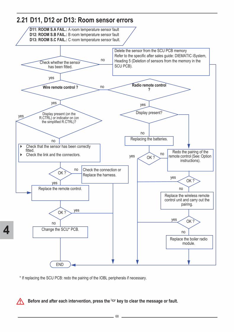
68
4
2.21 D11, D12 or D13: Room sensor errors
� Before and after each intervention, press the � key to clear the message or fault.
Display present (on the R.CTRL) or indicator on (on
the simplified R.CTRL)?
��Check that the sensor has been correctly fitted.
��Check the link and the connectors.
END
OK ?
Change the SCU* PCB.
Check whether the sensor has been fitted.
Wire remote control ?
Replace the remote control.
OK ?
D11: ROOM S.A FAIL.: A room temperature sensor faultD12: ROOM S.B FAIL.: B room temperature sensor faultD13: ROOM S.C FAIL.: C room temperature sensor fault.
no
Replacing the batteries.
yes
no
Radio remote control ?no
Check the connection or Replace the harness.
yes
yes
yes
no
no
yes
Display present?
no
noOK ?yes
Replace the wireless remote control unit and carry out the
pairing.
Redo the pairing of the remote control (See: Option
instructions).
OK ?yes
no
Replace the boiler radio module.
OK ?yes
no
yes
* If replacing the SCU PCB: redo the pairing of the IOBL peripherals if necessary.
Delete the sensor from the SCU PCB memoryRefer to the specific after sales guide: DIEMATIC iSystem, Heading 5 (Deletion of sensors from the memory in the SCU PCB).

69
4
2.22 D14: Communication with the boiler radio module (AD252)
� Before and after each intervention, press the � key to clear the message or fault.
D14: MC COM.FAILCommunication failure between the SCU PCB and the boiler radio module.
END
OK ?
Replace the boiler radio module and carry out the pairing (See: Option instructions).
��Check the installation of the boiler radiomodule (Refer to the instructionsdelivered with the option).
��Check the link and the connectors.
OK ?
no
yes
no
yes
Change the SCU* PCB.
* If replacing the SCU PCB: redo the pairing of the IOBL peripherals if necessary.
Replace the harness.

70
4
2.23 D27 or B13: Communication fault
� Before and after each intervention, press the � key to clear the message or fault.
- B13: BL. PCU COM: Communication error with the SCU PCB.- D27: PCU COM.FAILCommunication failure between the SCU and PCU PCBs.
END
Replace the harness.
Change the PCU PCB.
��Check the fuse: F2 on PCU (See section 6, chapter 5).��Check the connection and the connectors between the PCU and
SCU boards: connection between X11 (PCU) and J2 on SCU.��Check that the PCU / SCU PCB is powered up (green LED on or
flashing) See section 6, chapter 5.
noOK ?
yes
noOK ?
yes
Change the SCU* PCB.
* If replacing the SCU PCB: redo the pairing of the IOBL peripherals if necessary.

71
4
2.24 D29 or D30
� Before and after each intervention, press the � key to clear the message or fault.
2.25 D31
� Before and after each intervention, press the � key to clear the message or fault.
D29: IOBL.3WV B DEFD30: IOBL.3WV C DEFCommunication failure between the SCU PCB and the V3V module.
END
Set the IOBL parameter in the menu #CONFIGURATION to OFF.
D31: COM.IOBL FAIL.IOBL function OFF.
Change the SCU* PCB.
END
� Switch the boiler off and switch back on.� Set the IOBL parameter in the menu
#CONFIGURATION to OFF.
OK ?
Is the IOBL function used?
yes
Set the IOBL parameter in the menu #CONFIGURATION to OFF.
no
yes
no
* If replacing the SCU PCB: redo the pairing of the IOBL peripherals if necessary.

72
4
2.26 D32
D32: 5 RESET:ON/OFF5 resets done in less than an hour.
END
Switch off the boiler and wait 10 seconds. Then switch the boiler back on.

73
4
2.27 D37
� Before and after each intervention, press the � key to clear the message or fault.
D37: TA-S SHORT-CIRThere is a short circuit in the TAS.
END
OK ?
Disconnect the TAS connector on the SCU board:check that the fault displayed is TA-S DISCONNEC.
- Reconnect the TAS connector to the SCU board- Disconnect the TAS cable on the tank and check that the fault displayed is TA-S DISCONNEC.
Reconnect the TAS cable on the tank and reverse wires + and - on the SCU board.
OK ?
OK ?
yes
* If replacing the SCU PCB: redo the pairing of the IOBL peripherals if necessary
no
yes
Change the anode cable.
yes
no
no Change the SCU* PCB.
Replace the anode.

74
4
2.28 D38
� Before and after each intervention, press the � key to clear the message or fault.
D38: TA-S DISCONNECThe TAS is in open circuit or the tank is empty.
END
OK ?
Short circuit the TAS connector on the SCU board: check that the fault displayed is TA-S SHORT-CIR.
- Clear the short circuit on the TAS connector on the SCU board- Short circuit the TAS on the tank and check that the fault displayed is TA-S SHORT-CIR.
Check that the tank is full of water.
Check the programme version of the SCU board: this must be 1.5 or higher.
Replace the anode.
OK ?
OK ?
OK ?
Change the SCU* PCB.no
yes
OK ?
yes
yes
no
Update the programme version of the SCU board.
yes
yes
no
no
Change the anode cable.
Fill the tank with water.no
* If replacing the SCU PCB: redo the pairing of the IOBL peripherals if necessary.
TAS connector present?
yes
no Set the TAS parameter in the #CONFIGURATIONmenu to OFF.

75
5
INSTALLATIONCOMMISSIONING
G000008

76
5
Contents
1. Location of the appliance . . . . . . . . . . . . . . . . . . . . . . . . . . . . . . . . . . . . . . . . . . . . . . . . . . . . . 771.1 Location . . . . . . . . . . . . . . . . . . . . . . . . . . . . . . . . . . . . . . . . . . . . . . . . . . . . . . . . . . . . . . . . . . . . . . . . . . . . . 771.2 Ventilation . . . . . . . . . . . . . . . . . . . . . . . . . . . . . . . . . . . . . . . . . . . . . . . . . . . . . . . . . . . . . . . . . . . . . . . . . . . 77
2. Hydraulic connections . . . . . . . . . . . . . . . . . . . . . . . . . . . . . . . . . . . . . . . . . . . . . . . . . . . . . . . 782.1 Water treatment in the heating circuit . . . . . . . . . . . . . . . . . . . . . . . . . . . . . . . . . . . . . . . . . . . . . . . . . . . . . . 782.2 Installing the boiler in new installations (installations less than 6 months old) . . . . . . . . . . . . . . . . . . . . . . . 782.3 Installing the boiler in existing installations . . . . . . . . . . . . . . . . . . . . . . . . . . . . . . . . . . . . . . . . . . . . . . . . . . 792.4 Connection underfloor heating . . . . . . . . . . . . . . . . . . . . . . . . . . . . . . . . . . . . . . . . . . . . . . . . . . . . . . . . . . . . 792.5 Hydraulic connection of the heating circuit . . . . . . . . . . . . . . . . . . . . . . . . . . . . . . . . . . . . . . . . . . . . . . . . . . 802.6 Hydraulic connection of the water circuit for domestic use . . . . . . . . . . . . . . . . . . . . . . . . . . . . . . . . . . . . . . 812.7 Connecting the expansion vessel . . . . . . . . . . . . . . . . . . . . . . . . . . . . . . . . . . . . . . . . . . . . . . . . . . . . . . . . . 812.8 Connecting the condensate discharge pipe . . . . . . . . . . . . . . . . . . . . . . . . . . . . . . . . . . . . . . . . . . . . . . . . . . 82
3. Gas connection . . . . . . . . . . . . . . . . . . . . . . . . . . . . . . . . . . . . . . . . . . . . . . . . . . . . . . . . . . . . . 833.1 Connecting . . . . . . . . . . . . . . . . . . . . . . . . . . . . . . . . . . . . . . . . . . . . . . . . . . . . . . . . . . . . . . . . . . . . . . . . . . . 833.2 Gas categories . . . . . . . . . . . . . . . . . . . . . . . . . . . . . . . . . . . . . . . . . . . . . . . . . . . . . . . . . . . . . . . . . . . . . . . . 84
4. Flue gas system connections . . . . . . . . . . . . . . . . . . . . . . . . . . . . . . . . . . . . . . . . . . . . . . . . . 854.1 Installation . . . . . . . . . . . . . . . . . . . . . . . . . . . . . . . . . . . . . . . . . . . . . . . . . . . . . . . . . . . . . . . . . . . . . . . . . . . 854.2 Classification . . . . . . . . . . . . . . . . . . . . . . . . . . . . . . . . . . . . . . . . . . . . . . . . . . . . . . . . . . . . . . . . . . . . . . . . . 864.3 Maximum length for the air/flue connection pipes . . . . . . . . . . . . . . . . . . . . . . . . . . . . . . . . . . . . . . . . . . . . . 87
5. Electrical connections . . . . . . . . . . . . . . . . . . . . . . . . . . . . . . . . . . . . . . . . . . . . . . . . . . . . . . . 89
6. Filling the installation with water . . . . . . . . . . . . . . . . . . . . . . . . . . . . . . . . . . . . . . . . . . . . . . . 906.1 Filling . . . . . . . . . . . . . . . . . . . . . . . . . . . . . . . . . . . . . . . . . . . . . . . . . . . . . . . . . . . . . . . . . . . . . . . . . . . . . . . 906.2 Venting the heating . . . . . . . . . . . . . . . . . . . . . . . . . . . . . . . . . . . . . . . . . . . . . . . . . . . . . . . . . . . . . . . . . . . . 91
7. Draining the boiler . . . . . . . . . . . . . . . . . . . . . . . . . . . . . . . . . . . . . . . . . . . . . . . . . . . . . . . . . . 92
8. Check points before commissioning . . . . . . . . . . . . . . . . . . . . . . . . . . . . . . . . . . . . . . . . . . . 938.1 Checking the gas supply pressure . . . . . . . . . . . . . . . . . . . . . . . . . . . . . . . . . . . . . . . . . . . . . . . . . . . . . . . . . 938.2 Check the hydraulic circuit . . . . . . . . . . . . . . . . . . . . . . . . . . . . . . . . . . . . . . . . . . . . . . . . . . . . . . . . . . . . . . . 948.3 Check the electrical connections . . . . . . . . . . . . . . . . . . . . . . . . . . . . . . . . . . . . . . . . . . . . . . . . . . . . . . . . . . 94
9. Commissioning . . . . . . . . . . . . . . . . . . . . . . . . . . . . . . . . . . . . . . . . . . . . . . . . . . . . . . . . . . . . . 959.1 The boiler does not start up . . . . . . . . . . . . . . . . . . . . . . . . . . . . . . . . . . . . . . . . . . . . . . . . . . . . . . . . . . . . . . 959.2 In the event of run-off noise . . . . . . . . . . . . . . . . . . . . . . . . . . . . . . . . . . . . . . . . . . . . . . . . . . . . . . . . . . . . . . 95

77
5
1. Location of the appliance
1.1 LocationMCA boilers must be installed in a frost-free room.
The warranty does not apply to damage to the boiler caused by these instances. When installing the boiler, it is necessary tocomply with degree of protection IPX4D.
1.2 Ventilation
�If the heating appliance is installed in residential premises where people are present all the time, ensure sufficient ventilation pursuant to prevailing regulations.
�
In order to avoid damage to the boiler, it is necessary to prevent the contamination of combustion air bychlorine and/or fluoride compounds, which are particularly corrosive. These compounds are present, forexample, in aerosol sprays, paints, solvents, cleaning products, washing products, detergents, glues, snowclearing salts, etc.Therefore:
- Do not pull in air evacuated from premises using such products: hairdressing salons, drycleaners, industrial premises (solvents), premises containing refrigeration systems (risk ofrefrigerant leakage), etc.
- Do not stock such products close to the boilers.If the boiler and/or peripheral equipment are corroded by such chloride or fluoride compounds, thecontractual guarantee cannot be applied.
If the boiler is installed in a closed casing, respect the minimum dimensionsgiven in the diagram opposite. Also allow openings to obviate the followinghazards:
- Accumulation of gas- Heating of the box
Minimum cross section of the openings: S1 + S2 = 150 cm2
(1) Distance between the front of the appliance and the internal wall of the casing box.(2) Distance to allow on either side of the appliance.
100min.(1)
250min.
550 min.550 min.
250min.
S1
S2
G000198
50 min.(2)

78
5
2. Hydraulic connectionsThe installation must comply in all matters to the standards and rules which govern the work and interventions in individual andcollective homes, and other constructions. The boiler must be used only in closed circuit heating installations.A minimum water level safety device is not necessary; protection is guaranteed by the control system according to thedevelopment of the flow/return �T on the main exchanger.
2.1 Water treatment in the heating circuitCentral heating systems must be cleaned to eliminate debris (copper, strands, brazing flux) linked to the installation of the systemand deposits that can cause malfunctions (noise in the system, chemical reaction between metals). On the other hand, it isimportant to protect central heating systems against corrosion, scaling and microbiological growth by using a corrosion inhibitoradapted to all types of systems (steel, cast iron radiators, heated floor, PER).For Switzerland : The water quality must comply with the SICC directives No. 97-1F "Treatment of water intended for heating,steam, refrigeration and air conditioning installations".
� Specifications required for the heating water:The characteristics of the heating water are essential to guarantee good performance, operating safety and the longevity of theequipment used. Poor water quality in the heating circuits may damage the installation by leaving limescale deposits or causingcorrosion.To implement a condensing boiler with an aluminium-silicium heating body, we recommend the limiting values of the principalcharacteristics of the heating water with reference to the requirements of prevailing regulations(1):
- pH 6.5 to 8.5,- Conductivity < 500 µS/cm at 25°C.- Chloride content < 20 mg/l,- Suspended particles < 20 mg/l.
The requirements on water hardness are directly related to the total volume of the installation. The limiting value takes the installedoutput as its frame of reference. In the case of a cascade installation, the reference will be the limiting value of the water used forinitial filling corresponding to the smallest boiler.
(1) For Germany: VDI 2035
� Recommendations:- If the aforementioned conditions are not met or to provide additional protection to the unit (network, radiators, etc.), it will benecessary to resort to water treatment in the installation (product, filtration and tracking of parameters), which will factor in thevariety of materials present, including the aluminium heating body.
�- Take any precautions necessary to prevent the introduction into and formation of oxygen in the water in the installation by checking that the expansion vessel, the safety valve(s), etc. are correctly sized- Antifreeze products: ensure that these are compatible with aluminium and, if need be, with other components in the installation.
- Limit topping up the installation with water to the minimum. If using treatment, check the properties of the water and theconcentrations of active substances in the installation at least 2 times a year.- De Dietrich Thermique recommends the following manufacturers: Cillit - Climalife - Permo - Sentinel.
2.2 Installing the boiler in new installations (installations less than 6months old)
Water hardness
Useful output Pn (kW)Concentration
°dH °f� 70 2.8 - 20 5 - 2070 - 200 2.8 - 20 5 - 15
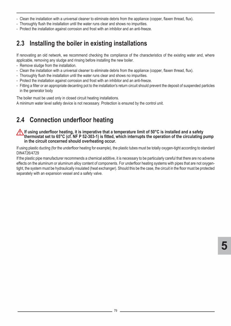
79
5
- Clean the installation with a universal cleaner to eliminate debris from the appliance (copper, flaxen thread, flux).- Thoroughly flush the installation until the water runs clear and shows no impurities.- Protect the installation against corrosion and frost with an inhibitor and an anti-freeze.
2.3 Installing the boiler in existing installationsIf renovating an old network, we recommend checking the compliance of the characteristics of the existing water and, whereapplicable, removing any sludge and rinsing before installing the new boiler.- Remove sludge from the installation.- Clean the installation with a universal cleaner to eliminate debris from the appliance (copper, flaxen thread, flux).- Thoroughly flush the installation until the water runs clear and shows no impurities.- Protect the installation against corrosion and frost with an inhibitor and an anti-freeze.- Fitting a filter or an appropriate decanting pot to the installation's return circuit should prevent the deposit of suspended particles
in the generator bodyThe boiler must be used only in closed circuit heating installations. A minimum water level safety device is not necessary. Protection is ensured by the control unit.
2.4 Connection underfloor heating
�If using underfloor heating, it is imperative that a temperature limit of 50°C is installed and a safety thermostat set to 65°C (cf. NF P 52-303-1) is fitted, which interrupts the operation of the circulating pump in the circuit concerned should overheating occur.
If using plastic ducting (for the underfloor heating for example), the plastic tubes must be totally oxygen-tight according to standardDIN4726/4729If the plastic pipe manufacturer recommends a chemical additive, it is necessary to be particularly careful that there are no adverseeffects on the aluminum or aluminum alloy content of components. For underfloor heating systems with pipes that are not oxygen-tight, the system must be hydraulically insulated (heat exchanger). Should this be the case, the circuit in the floor must be protectedseparately with an expansion vessel and a safety valve.

80
5
2.5 Hydraulic connection of the heating circuit
{ Heating flowConnection by internal brazing : Ø 22 mmorPressfitting: Ø 22 mm.
z Heating returnConnection by internal brazing : Ø 22 mmorPressfitting: Ø 22 mm.
1. Disconnector2. Discharge hose connection3. Connection to the cold water supply4. Connection hose to the heating circuit
� The boiler is factory fitted with a safety valve mounted on the lefthydrobloc.
T001625-A
41
32
G000
167A
T001633-B
Models shown: MCA... MI / BIC

81
5
2.6 Hydraulic connection of the water circuit for domestic use
2.7 Connecting the expansion vesselThe boiler is fitted as standard with an 12-litre expansion vessel (Except MCA 35... models). If the water volume is greater than150 litres or the static height of the system exceeds 5 metres, an additional expansion vessel must be fitted.
Conditions of validity of the table:� 3-bar safety valve� Average water temperature: 70 °C
Flow temperature: 80 °CReturn temperature: 60 °C
� The filling pressure in the system is lower than or equal to the initial pressure in the expansion vessel.
(1) Factory configuration
� Domestic cold water inlet : MCA...MI, MCA...BIC VersionsorPrimary return, DHW tank : MCA 10 - 15 - 25 - 35 Versions (when DHW tank is connected)Connection by internal brazing: Ø 16 mm.
� Domestic hot water outlet : MCA...MI, MCA...BIC VersionsorPrimary flow to DHW tank : MCA 10 - 15 - 25 - 35 Versions (when DHW tank is connected)Connection by internal brazing: Ø 16 mmorPressfitting - Depending on country.
Initial pressure of the expansion vessel
Volume of the expansion vessel depending on the volume of the installation (in litres)
100 125 150 175 200 250 300 > 3000.5 bar 4.8 6.0 7.2 8.4 9.6 12.0 14.4 Volume of the installation x 0.0481 bar 8.0 10.0 12.0(1) 14.0 16.0 20.0 24.0 Volume of the installation x 0.0801.5 bar 13.3 16.6 20.0 23.3 26.6 33.3 39.9 Volume of the installation x 0.133
T001626-A

82
5
2.8 Connecting the condensate discharge pipe
�Do not make a fixed connection owing to maintenance work on the siphon.� Do not plug the condensate discharge pipe.� Set the discharge pipe at a gradient of at least 30 mm per metre, maximum horizontal length 5 metres.� Do not drain condensation water into a roof gutter at any time (corrosion).� Connect the condensate discharge pipe in accordance with prevailing standards.
� For Germany: Standard DIN 1986 and ATV working instructions no A251.
� Fit a PVC discharge pipe, diameter 32 mm or more, leading to thesewers
� Mount the flow collector� Into this, insert the condensate collector hose coming from the siphon� and the safety valve �.
� Into this, insert the discharge hose from the disconnector� Mount a trap or a siphon in the discharge pipe.
T001873-C

83
5
3. Gas connection
3.1 Connecting
�Caution� Close the main gas valve before starting work on the gas pipes.� Before mounting, check that the gas meter has sufficient capacity. To do this, you should keep in mind the consumption of
all domestic appliances. � If the gas meter has too low a capacity, inform the energy supply company.� Ensure that there is no dust in the gas pipe. Blow into the pipe or shake it before mounting.� We recommend installing a gas filter on the gas pipe to prevent clogging of the gas valve unit. � Connect the gas pipe in accordance with prevailing standards and regulations.
� All countries: The diameters of the pipes must be defined inaccordance with the standards in force in your country.France: Pipe diameters must be defined in accordance with ATG's(Association Technique de Gaz) B171 specifications.
� Gas inlet pipe (diameter: Depending on country)France: Connection by internal brazing: Ø 18 mm.
For Belgium:� The boiler installation and gas connection must be carried out by a
qualified professional in compliance with the NBN D 51.003, NBN D30.003, NBN B 61.001, NBN B 61.002 and NBN D 51.006 standards.An ARGB approved stop valve must be fitted in the pipe leading to andclose to the boiler.
1. Connect the gas inlet pipe2. Mount a gas isolation valve on this pipe, directly under the boiler3. Connect the gas pipe to the gas shut off valve
��Connection by clamping Ø 15.
�Do not touch sealed components.
T001621-A
T002915-A

84
5
3.2 Gas categories� For FranceThe boiler is preset in the factory to operate on natural gas H (G20)
� For Belgium
� The boiler is preset in the factory to operate on natural gases H (G20) and L (G25)
� For ItalyThe boiler is preset in the factory to operate on natural gas H (G20)
� For PolandThe boiler is preset in the factory to operate on natural gas E (G20)
� For other countries: see the nameplate or the instructions that come with the appliance.
Boiler type Gas category Gas type Connection pressure (mbar)
MCA 15 -MCA 25MCA 25/28 MIMCA 25/28 BICMCA 35
II2ESi3P
Natural gas H (G20) 20
Natural gas L (G25) 25
Propane (G31) 37
Boiler type Gas category Gas type Connection pressure (mbar)
MCA 15 -MCA 25MCA 25/28 MIMCA 35MCA 35/40 MI
I2E(S)BNatural gas H (G20) 20
Natural gas L (G25) 25
I3P Propane (G31) 37
Boiler type Gas category Gas type Connection pressure (mbar)
MCA 10 - MCA 15 - MCA 25MCA 25/28 MIMCA 25/28 BICMCA 35
II2HM3P
Natural gas H (G20) 20
Propane (G31) 37
Propane air (G230) 20
Boiler type Gas category Gas type Connection pressure (mbar)
MCA 15 - MCA 25MCA 25/28 MI II2ELwLs3P
Natural gas E (G20) 20Natural gas Lw (G27) 20Natural gas Ls (G2.350) 13Propane (G31) 37
MCA 35 II2ELw3P
Natural gas E (G20) 20Natural gas Lw (G27) 20Propane (G31) 37

85
5
4. Flue gas system connections
4.1 Installation- The boiler must be connected in compliance with prevailing provisions and standards, i.e. with conduits intended to evacuate
pressurized flue gases.- The pipes must allow no leakage of flue gases and be resistant to corrosion. They must be installed in such a way that their
relative position in relation to the special evacuation system cannot be modified even after service interventions.- The appliance, including its connection conduit, must remain accessible with a view to maintenance and repair.- Maximum length = lengths of the straight air/flue gas ducts + equivalent lengths of other components.
�Caution� For France: Boilers can only be installed with flue gas connection pipes provided by the constructor.
For other countries: the boiler must be connected with an approved flue gas system.� The clear section must comply with the standard.� The chimney must be swept before the installation of the evacuation conduit.
� Equivalent conduit lengths (metres) - flue gas system delivered by De Dietrich Thermique
Connection diameter Ø 60/100 Ø 80/125 Ø 60 - rigidØ 80 - rigid
Ø 80 - FlexiblePPS Alu
Elbow 87° 1.1 1.5 1.1 1.9 1.2 -
Elbow 45° 0.8 1.0 0.6 1.2 0.9 -
Elbow 30° 0.7 - 0.9 0.4 - -
Elbow 15° 0.5 - 0.6 0.2 - -
Right inspection tube 0.5 0.6 0.3 0.3 0.5 0.3
87° inspection elbow - 2.0 - 0.7 -
Inspection T 2.2 2.7 2.9 4.2 2.8
Inspection tube for flexible pipe - - - - - 0.3

86
5
4.2 Classification� As a guide for France. Other connections are possible. Comply with current regulations and national and local standards.
x : (For Germany only) The letter x means that none of the components carrying pressurized flue gases, comes into direct contact with the ambiant air of the room.
1. Configuration type C13XAir/flue gas connection by means of concentric pipes to a horizontal terminal (so-called forced flue)
2. Configuration type C33xAir/flue gas connection by means of concentric pipes to a vertical terminal (roof outlet)
3. Configuration type C93xAir/flue gas connection by concentric pipes in the boiler room and single pipes in the chimney (combustive air in counter current in the chimney)or
4. Configuration type C93xAir/flue gas connection by concentric pipes in the boiler room and single "flex" in the chimney (combustive air in counter current in the chimney)
5. Configuration type C53Air and flue gas connection separated by means of a bi-flow adapter and single pipes (combustive air taken from outside)
6. Configuration type B23PConnection to a chimney using a connection kit - combustive air taken from the boiler room
12. Configuration type C43XAir/flue gas connection to a collective conduit for watertight boilers (3CE system)
C93x C93x
MCR_F0011-C

87
5
4.3 Maximum length for the air/flue connection pipes� MCA 10 - MCA 15 - MCA 25 - MCA 35
�(1) The max length in the flue gas pipe (configurations C93, B23P) of the elbow bracket at the outlet must not exceed:- 30 m for rigid PPS- 25 m for flexible PPSIf longer lengths are used, holding clamps must be added per sections of 25 or 30 metres.
On concentric flue gas discharge systems (forced flue), the C02 level in the annular space in the measurement piping can also bechecked. The flue gas discharge system is considered leak-proof if the measured CO2 level is lower than 0.2% (When the boileroperates at maximum output).
Type of air/flue gas connection DiameterMaximum length Lmax (m)
INNOVENS MCA10 15 25 35
C13xConcentric pipes connected to a horizontal terminal Alu or PPS
60/100 mm 4.1 12 3.5 3.580/125 mm 8 12.3 20 17.6
C33xConcentric pipes connected to a vertical terminal Alu or PPS
60/100 mm 5.9 13 4.9 -80/125 mm 6.8 10.7 20 19
C93x
Concentric pipes in the boiler roomSingle conduits in the chimney (combustive air in counter-current)
Alu or PPS 60/100 mm60 mm (Rigid duct) 8.5 15 8.1 2.8
PPS 60/100 mm80 mm (Rigid duct) 5.8 9.9 20 18
PPS 80/125 mm80 mm (Rigid duct) - - - 20
Concentric pipes in the boiler roomSingle flexible pipe in the chimney (combustive air in counter-current)
PPS 80/125 mm80 mm (Flexible duct) 11.1 20 20
C53
Bi-flow adapter and separate single air/flue gas ducts (combustive air taken from outside)
Alu 60/100 mm2 x 80 mm 50 40 40 32
B23PChimney (rigid or flexible duct in chimney,combustive air taken from the premises) PPS
80 mm (Rigid duct) 50 40(1) 40(1) 40(1)80 mm (Flexible duct) 45 40(1) 40(1) 28(1)
C43x Collective conduit for sealed boiler (3CE) To determine the size of such a system, consult the supplier of the 3CE conduit

88
5
� MCA 25/28 MI - MCA 35/40 MI - MCA 25/28 BIC
�(1) The max length in the flue gas pipe (configurations C93x, B23P) of the elbow bracket at the outlet must not exceed: - 30 m for rigid PPS- 25 m for flexible PPSIf longer lengths are used, holding clamps must be added per sections of 25 or 30 metres.
� On concentric flue gas discharge systems (forced flue), the C02 level in the annular space in the measurement piping canalso be checked. The flue gas discharge system is considered leak-proof if the measured CO2 level is lower than 0.2% (Whenthe boiler operates at maximum output).
Type of air/flue gas connection Connectiondiameter
Maximum length Lmax (m)INNOVENS MCA
25/28 MI25/28 BIC 35/40 MI
C13xConcentric pipes connected to a horizontal terminal Alu or PPS
60/100 mm 4.2 380/125 mm 20 16.6
C33x Concentric pipes connected to a vertical terminal Alu or PPS60/100 mm 5.5 -80/125 mm 20 18.5
C93x
Concentric pipes in the boiler roomSingle conduits in the chimney (combustive air in counter-current)
Alu or PPS 60/100 mm60 mm (Rigid duct) 9 2.4
PPS 60/100 mm80 mm (Rigid duct) 20 8
Concentric pipes in the boiler roomSingle flexible pipe in the chimney (combustive air in counter-current)
80/125 mm80 mm (Flexible duct) 20 -
C53Bi-flow adapter and separate single air/flue gas ducts (combustive air taken from outside) Alu 60/100 mm
2 x 80 mm 40 21
B23PChimney (rigid or flexible duct in chimney,combustive air taken from the premises) PPS
80 mm (Rigid duct) 40(1) 4080 mm (Flexible duct) 40(1) 26.5
C43x Collective conduit for sealed boiler (3CE) To determine the size of such a system, consult the supplier of the 3CE conduit

89
5
5. Electrical connections
�
- Any interventions inside the boiler must be done by a qualified and authorised person- Before any interventions, ensure that the electrical power is disconnected. - Only qualified professionnals may carry out electrical connections, always with the power off. - The earthing shall comply with local standardsThe earthing must comply with the NFC 15.100 (France) or the RGPT (Belgium) standards.- Under no circumstances must sensor cables (very low voltage) be placed in cable ducts or channelscarrying cables supplying 230 V. Furthermore, a minimum distance of 10 cm should be kept betweencables supplying very low voltage and cables supplying 230 V.
The mains supply is made via the cable C connected to themains:230 V, 50 Hz.
A. Routing of the 230 V cablesB. Routing of the sensor cablesC. Power supply cableD. Spare fuses: Main fuse: 6.3 AT (F1)E. Spare fuses: 2 AT fuse (F2)
C002336-E
C
A BE
D
�Danger:The PCU PCB remains at a voltage of 230 V regardless of the position of the ON/OFF switch.

90
5
6. Filling the installation with water
6.1 Filling
�The first start-up is to be performed by your installation/commissioningengineer. Operation while the condensation water siphon is empty maydamage the boiler.
�Before filling, open the valves on every radiator in the installation.Water treatment in the heating circuit: See section 5, chapter 2.1.
1. Open the cold water inlet and heating outlet valves.
2. Open the disconnector valves (During filling, air can escape from thesystem via the automatic air vent).
3. Close the disconnector valves when the manometer indicates a pressureof 2 bar.
� Calibration of the safety valve: 3 bar
4. Checking the water-side connections for tightness.
1 23
4
T000181-B
T001618-A
1
2
T001619-A
2
12 bar
T001507-B
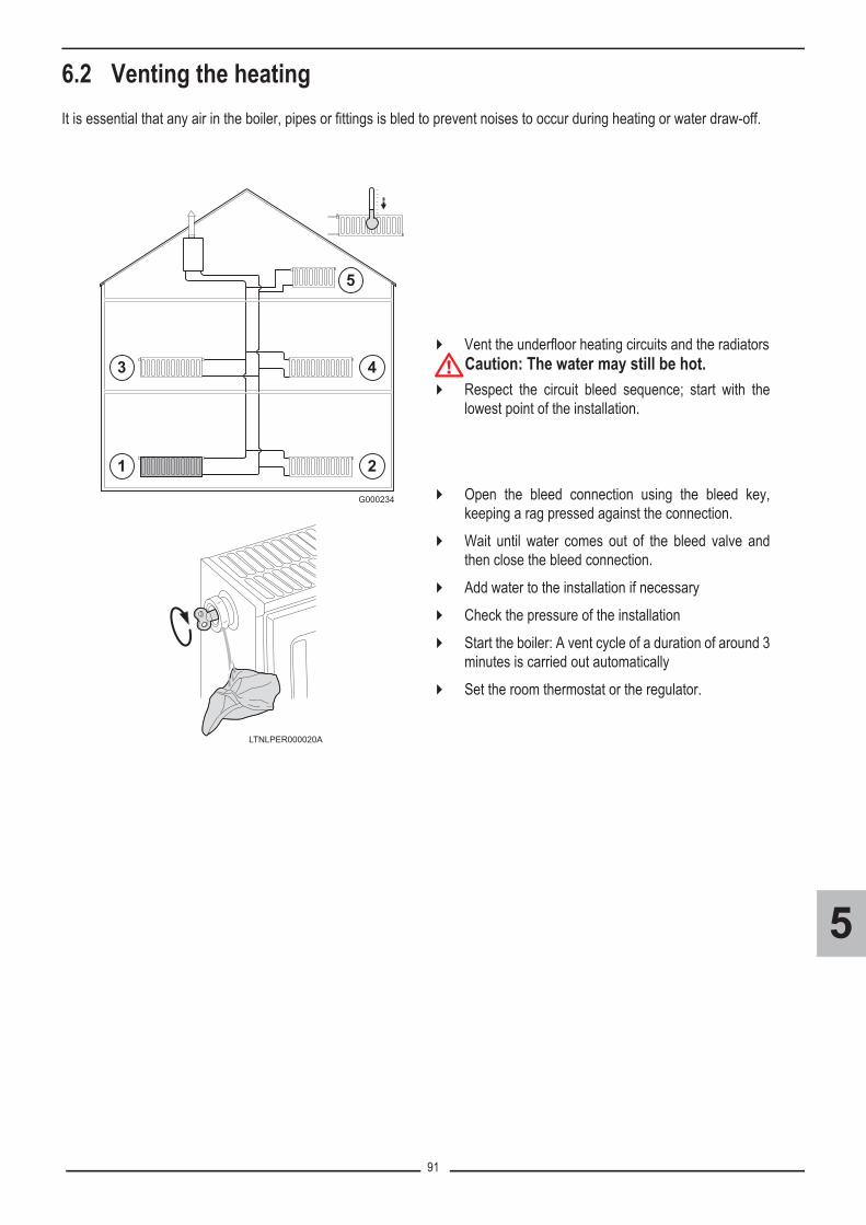
91
5
6.2 Venting the heatingIt is essential that any air in the boiler, pipes or fittings is bled to prevent noises to occur during heating or water draw-off.
� Vent the underfloor heating circuits and the radiators
�Caution: The water may still be hot.� Respect the circuit bleed sequence; start with the
lowest point of the installation.
� Open the bleed connection using the bleed key,keeping a rag pressed against the connection.
� Wait until water comes out of the bleed valve andthen close the bleed connection.
� Add water to the installation if necessary� Check the pressure of the installation� Start the boiler: A vent cycle of a duration of around 3
minutes is carried out automatically� Set the room thermostat or the regulator.
G000234

92
5
7. Draining the boiler
�Caution: The water may still be hot.� Switch off the boiler.� Cut the gas supply to the boiler.� Close the main water valve,� If it is not necessary to drain the entire installation, close the
boiler's isolating valves.
� The isolating flow and return valves are fitted with a drainvalve (see illustration opposite)
� Drain the boiler.
H2O
21
G000141
G000
181A

93
5
8. Check points before commissioning
8.1 Checking the gas supply pressure� Check that the gas type supplied matches the data shown on the boiler's data plate.
�Caution: Do not put the boiler into operation if the supplied gas is not in accordance with the approved gas types. To ascertain the gas types permitted, see chapter: Gas categories - Heading 5 - Chapter 3.2.
.
�The first start-up is to be performed by your installation/commissioningengineer. Operation while the condensation water siphon is empty maydamage the boiler.
�
Water treatment in the heating circuit: As most heating systems are designed from various materials, itis recommended to provide a water treatment to prevent or reduce the problems(metal corrosion,formation of scale and sludge, microbiological contamination, chemical changes in the untreated systemwater).See section 2, chapter 1.
�If the pressure exceeds the authorised pressure range (Natural gas G20 = 17-25 mbar,Natural gas G25 = 20-30 mbar; Propane G31 = 37-50 mbar): Suspend commissioning. Inform the gas supply company.
�Caution: Ensure that the boiler is switched off.1. Open the main gas supply.2. Unscrew the two screws located under the front panel by a quarter turn
and remove the panel.3. Tilt the control box forwards by opening the holding clips located at the
sides.4. Check the gas supply pressure at the pressure outlet C on the gas valve
unit - Connect the manometer.5. Check the tightness of the gas connections made after the gas valve
unit in the boiler.6. Check the tightness of the gas line, including the gas valves. The test
pressure must not exceed 60 mbar.7. Purge the gas supply pipe within the boiler by unscrewing the pressure
outlet on the gas block. Tighten the measurement point when the pipehas been sufficiently purged.
8. Check the tightness of the gas connections in the boiler.
T001518-B
C

94
5
8.2 Check the hydraulic circuit� Check that there are no leaks on the hydraulic connections� Check the water pressure in the heating system. The hydraulic pressure must reach a minimum of 0.8 bar. If necessary, top
up the water level in the heating system (recommended hydraulic pressure between 1.5 and 2 bar)If the hydraulic pressure is lower than 0.8 bar, the symbol bar flashes .
� During the venting phase (display: DISGAS M20), if the pressure is insufficient (less than 0.8 bar), the fault DEF WATERMISSING (code L250) is displayed. The boiler goes into default, and then restarts automatically after 30 minutes or when thefault is cleared using the � key.
The hydraulic pressure can be read as follows:- On the mechanical pressure gauge, located under the boiler- On the screen, via the symbol �
Water pressure level:�: 0,9 to 1,1 bar�: 1,2 to 1,5 bar�: 1,6 to 1,9 bar�: 2,0 to 2,3 bar�: > 2,4 bar
- by pressing the � button, #MEASURES menu, Parameter PRESSUREor In the menu SUPPORT / #PARAMETERS / PRESSURE (Key�: Used to display the curve of the parameterselected).
� Filling the siphon:
8.3 Check the electrical connections� Check the electrical connections to the thermostat and the other external controls.� Check the other connections.
� Remove the air vent hose above the siphon,� Remove the siphon,� Fill the siphon with clean water up to the mark,� Re-assemble the siphon. Mount the vent hose above the siphon.
T001523-B

95
5
9. Commissioning
� Description of the DIEMATIC iSystem control panel: See section 1, chapter 1, or:Refer to the specific after sales guideDIEMATIC iSystem.
�Caution: Operation while the condensation water siphon is empty may damage the boiler� Check the condensate discharge siphon; it must be filled with clean water up to the mark� Tilt the control box upwards again and fasten it using the clips located at the sides� Open the main gas supply� Open the gas valve on the boiler� Turn on the boiler using the on/off switch. � The first time the boiler is powered up, the #LANGUAGE menu is displayed.Select the desired language by turning the
rotary button. To confirm, press the rotary button.� The boiler will begin an automatic venting-programme (which lasts approx. 3 minutes) and will do this every time the power
supply is isolated.� The rest of the operation is automatic.� The boiler operates according to the settings programmed in the factory.
9.1 The boiler does not start up� No information is shown on the display.
- Check the mains supply voltage- Check the fuses- Check the connection of the power cable to the connector X1 on the PCU PCB
� If there is a problem, the error is displayed on the screen.
� See section 4.
� If a DHW sensor is connected and the anti-legionella function is activated, the boiler starts to heat the water in the DHW tankas soon as the vent programme has been completed. The heating time depends on the size of the DHW installation.
9.2 In the event of run-off noise� Vent the air in the heating system� If flow noise can be heard in the system, it is possible to reduce the maximum pump speed with the parameter MAX.PUMP
SPEED. First of all, vent the heating system.If circulation in the radiators is too low or the radiators do not fully heat up, increase the minimum pump speed with theparameter MIN.PUMP SPEED.
� The first start-up is to be performed by your installation/commissioning engineer.
Français - Deutsch - English - Italiano - Espanol - Nederlands- Pycck - Polski - Türk -
bar
1
1
2
2
��
STD� � �
�
0 2 4 6 8 10 12 14 16 18 22 2420
�� � � ��
LANGUE FRANCAIS
C002286-C
C002366-B

96
5

97
6
CONTROLS AND SETTINGS
3,8 k

98
6
Contents
1. Information to be noted before contacting Technical Assistance . . . . . . . . . . . . . . . . . . . . 99
2. Accessing the boiler components . . . . . . . . . . . . . . . . . . . . . . . . . . . . . . . . . . . . . . . . . . . . . 100
3. Re-assembling the boiler . . . . . . . . . . . . . . . . . . . . . . . . . . . . . . . . . . . . . . . . . . . . . . . . . . . . 101
4. Maintenance . . . . . . . . . . . . . . . . . . . . . . . . . . . . . . . . . . . . . . . . . . . . . . . . . . . . . . . . . . . . . . 1024.1 Checking the hydraulic pressure . . . . . . . . . . . . . . . . . . . . . . . . . . . . . . . . . . . . . . . . . . . . . . . . . . . . . . . . . . . . . . . . . 1024.2 Checking the expansion vessel . . . . . . . . . . . . . . . . . . . . . . . . . . . . . . . . . . . . . . . . . . . . . . . . . . . . . . . . . . . . . . . . . . 1024.3 Checking the ionization current . . . . . . . . . . . . . . . . . . . . . . . . . . . . . . . . . . . . . . . . . . . . . . . . . . . . . . . . . . . . . . . . . . 1024.4 Checking the transfer capacity . . . . . . . . . . . . . . . . . . . . . . . . . . . . . . . . . . . . . . . . . . . . . . . . . . . . . . . . . . . . . . . . . . 1024.5 Checking the tightness of the flue gas evacuation and air inlet connections . . . . . . . . . . . . . . . . . . . . . . . . . . . . . . . . 1034.6 Checking combustion . . . . . . . . . . . . . . . . . . . . . . . . . . . . . . . . . . . . . . . . . . . . . . . . . . . . . . . . . . . . . . . . . . . . . . . . . 1034.7 Checking the automatic air vent . . . . . . . . . . . . . . . . . . . . . . . . . . . . . . . . . . . . . . . . . . . . . . . . . . . . . . . . . . . . . . . . . 1044.8 Checking the safety valve (Heating) . . . . . . . . . . . . . . . . . . . . . . . . . . . . . . . . . . . . . . . . . . . . . . . . . . . . . . . . . . . . . . 1054.9 Checking the safety valve, DHW (Only MCA 25/28 BIC) . . . . . . . . . . . . . . . . . . . . . . . . . . . . . . . . . . . . . . . . . . . . . . . 1054.10 Inspection of the siphon and the condensate discharge pipe . . . . . . . . . . . . . . . . . . . . . . . . . . . . . . . . . . . . . . . . . . 1064.11 Checking and cleaning the burner, the fan and the heat exchanger . . . . . . . . . . . . . . . . . . . . . . . . . . . . . . . . . . . . . 1064.12 Cleaning the plate exchanger and the water filter cartridge (depending on the version)
. . . . . . . . . . . . . . . . . . . . . . . . . . . . . . . . . . . . . . . . . . . . . . . . . . . . . . . . . . . . . . . . . . . . . . . . . . . . . . . . . . . . . . . . . . . 1094.13 Checking the domestic hot water tank (When the boiler is connected to a DHW tank) . . . . . . . . . . . . . . . . . . . . . . . 111
5. Checking the mains supply and connections between boards . . . . . . . . . . . . . . . . . . . . . 114
6. Checking the components . . . . . . . . . . . . . . . . . . . . . . . . . . . . . . . . . . . . . . . . . . . . . . . . . . . 1186.1 Switching off . . . . . . . . . . . . . . . . . . . . . . . . . . . . . . . . . . . . . . . . . . . . . . . . . . . . . . . . . . . . . . . . . . . . . . . . . . . . . . . . 1186.2 Sensors . . . . . . . . . . . . . . . . . . . . . . . . . . . . . . . . . . . . . . . . . . . . . . . . . . . . . . . . . . . . . . . . . . . . . . . . . . . . . . . . . . . . 1196.3 Ignition/ionization electrode - Ignition transformer . . . . . . . . . . . . . . . . . . . . . . . . . . . . . . . . . . . . . . . . . . . . . . . . . . . . 1246.4 Gas valve (Gas Block) . . . . . . . . . . . . . . . . . . . . . . . . . . . . . . . . . . . . . . . . . . . . . . . . . . . . . . . . . . . . . . . . . . . . . . . . . 1256.5 Reversal valve (or 3-way valve) . . . . . . . . . . . . . . . . . . . . . . . . . . . . . . . . . . . . . . . . . . . . . . . . . . . . . . . . . . . . . . . . . . 1276.6 Flowmeter (...MI versions only) . . . . . . . . . . . . . . . . . . . . . . . . . . . . . . . . . . . . . . . . . . . . . . . . . . . . . . . . . . . . . . . . . . 1286.7 Boiler pump . . . . . . . . . . . . . . . . . . . . . . . . . . . . . . . . . . . . . . . . . . . . . . . . . . . . . . . . . . . . . . . . . . . . . . . . . . . . . . . . . 1296.8 DHW pump (Only MCA 25/28 BIC) . . . . . . . . . . . . . . . . . . . . . . . . . . . . . . . . . . . . . . . . . . . . . . . . . . . . . . . . . . . . . . . 1306.9 Pressure sensor (or Pressure switch, PS) . . . . . . . . . . . . . . . . . . . . . . . . . . . . . . . . . . . . . . . . . . . . . . . . . . . . . . . . . . 1306.10 Fan . . . . . . . . . . . . . . . . . . . . . . . . . . . . . . . . . . . . . . . . . . . . . . . . . . . . . . . . . . . . . . . . . . . . . . . . . . . . . . . . . . . . . . . 1316.11 Safety thermostat (HLS) . . . . . . . . . . . . . . . . . . . . . . . . . . . . . . . . . . . . . . . . . . . . . . . . . . . . . . . . . . . . . . . . . . . . . . 1326.12 Connecting the PCU PCB to IN BL . . . . . . . . . . . . . . . . . . . . . . . . . . . . . . . . . . . . . . . . . . . . . . . . . . . . . . . . . . . . . . 133
7. Specific maintenance operations . . . . . . . . . . . . . . . . . . . . . . . . . . . . . . . . . . . . . . . . . . . . . 1347.1 Replacing the reversal valve . . . . . . . . . . . . . . . . . . . . . . . . . . . . . . . . . . . . . . . . . . . . . . . . . . . . . . . . . . . . . . . . . . . . 1347.2 Replacing the flue gas non-return valve . . . . . . . . . . . . . . . . . . . . . . . . . . . . . . . . . . . . . . . . . . . . . . . . . . . . . . . . . . . 1357.3 Replacing the gas valve . . . . . . . . . . . . . . . . . . . . . . . . . . . . . . . . . . . . . . . . . . . . . . . . . . . . . . . . . . . . . . . . . . . . . . . . 1367.4 Replacing the boiler tanks (MCA 25/28 BIC) . . . . . . . . . . . . . . . . . . . . . . . . . . . . . . . . . . . . . . . . . . . . . . . . . . . . . . . . 137
8. Gas settings / Adapting to another gas type (with new gas valve version) . . . . . . . . . . . 1388.1 Installation / Checking the gas diaphragm (with new gas valve version) . . . . . . . . . . . . . . . . . . . . . . . . . . . . . . . . . . . 1398.2 Setting the air/gas ratio (Full load / Part load) (with new gas valve version) . . . . . . . . . . . . . . . . . . . . . . . . . . . . . . . . 1408.3 O2/CO2 checking and setting value (with new gas valve version) . . . . . . . . . . . . . . . . . . . . . . . . . . . . . . . . . . . . . . . . 1428.4 Basic setting for the gas/air ratio . . . . . . . . . . . . . . . . . . . . . . . . . . . . . . . . . . . . . . . . . . . . . . . . . . . . . . . . . . . . . . . . . 145
9. Gas settings / Adapting to another gas type (with old gas valve) . . . . . . . . . . . . . . . . . . . . . . 1469.1 Checking the gas diaphragm (with old gas valve) . . . . . . . . . . . . . . . . . . . . . . . . . . . . . . . . . . . . . . . . . . . . . . . . . . . . 1479.2 Setting the air/gas ratio (Full load / Part load, with old gas valve) . . . . . . . . . . . . . . . . . . . . . . . . . . . . . . . . . . . . . . . . 1489.3 O2/CO2 checking and setting value (with old gas valve) . . . . . . . . . . . . . . . . . . . . . . . . . . . . . . . . . . . . . . . . . . . . . . . 150
10. Setting the fan speeds in accordance with the gas type . . . . . . . . . . . . . . . . . . . . . . . . . 153

99
6
1. Information to be noted before contacting TechnicalAssistance
* The parameter is only displayed if the corresponding option is connected.
� Information on the appliance (to be found on the nameplate):Boiler modelGas typeSerial number� Other information to be noted:��User parameter level (� key), #MEASURES menu:
Parameter Display ? Description
CTRL ... 1.2, 1.3, 1.4, 1.5... Version of the SCU PCB programme��Installer parameter level - #SYSTEM menu (Displaying the parameters in extended mode):
Parameter Display ? Description
CIRC. A:* DIRECTPROGRAM.H.TEMPDHWDHW ELECDISAB.
CIRC. B:* 3WV / SWIM.P. /DIRECTCIRC. C:* 3WV / SWIM.P. /DIRECTO.PUMP A CH.PUMP A
CIRC.AUXDHW LOOPPRIMARY PUMPORDER BURNERFAILURE
O.DHW: PUMP / RV��"After Sales" level - #TEST INPUTS menu
Parameter Display ? Description
TYPE Generator typeVER.ROM Version of the PCU PCB programmeVERS.PARAM PCU Version of the PCU PCB parametersMC.VERSION* Version of the boiler radio module programmeOUTSI.S.VERSION* Version of the radio outside temperature sensor programmeR.CTRL A* ON/OFFR.CTRL B* ON/OFFR.CTRL C* ON/OFFID MC IOBL* Identifying number of the IOBL boiler moduleIOBL.VERSION* IOBL version of the SCU PCB

100
6
2. Accessing the boiler components
Board access
1. Unscrew the 2 screws under the front panel by a quarter turn2. Remove the front panel
3. Open the holding clips located on the sides4. Tilt the control panel forward
5. Lift the clip located in front of the control panel6. Lift the control panel cover
7. Unclip the PCB cover
C002325-C
2
1
C002326-B
4
3
3
C002327-B
5
6
6
C002330-C
7

101
6
3. Re-assembling the boiler
� Ensure that the fastening clips are correctly put in place.
�Observe the assembly sequence
� Filling and refitting the syphon.� Mount the vent hose above the siphon.
� Close the boiler
� Carefully open the main water valve, fill the installation, vent it and, if need be, top it up with water.
T001523-B
G000170
CheckContrôler
Clips

102
6
4. MaintenanceMCA boilers require little maintenance. An annual inspection is compulsory.If, on annual inspection, the combusted gas analysis is not in compliance, a setting combustion operation must be carried out (Seesection 6, chapter 8 / 9).
�Maintenance operations must be done by a qualified engineer.Only original spare parts must be used.During inspection and maintenance operations, always replace all gaskets on the parts removed.
4.1 Checking the hydraulic pressureThe hydraulic pressure must reach a minimum of 0.8 bar. If the hydraulic pressure is lower than 0.8 bar, the symbol bar flashes.� If necessary, top up the water level in the heating system (recommended hydraulic pressure between 1.5 and 2 bar).The hydraulic pressure can be read as follows:
- On the mechanical pressure gauge, located under the boiler- On the screen, via the symbol :
Water pressure level:�: 0,9 to 1,1 bar�: 1,2 to 1,5 bar�: 1,6 to 1,9 bar�: 2,0 to 2,3 bar�: > 2,4 bar
- by pressing the � button, To select the #MEASURES menu, Parameter PRESSUREorIn the menu SUPPORT / #PARAMETERS / PRESSURE.
4.2 Checking the expansion vesselCheck the expansion vessel and replace it if necessary. See section 5, chapter 2.7 Connecting the expansion vessel.Version MCA 25/28 BIC: Check also the DHW expansion vessel (pre-loading pressure 2.5 bar)
4.3 Checking the ionization current� The ionization current is displayed in the menu #MEASURES, Parameter CURRENT. The value displayed for this
parameter corresponds to the ionization current.� Replace the ionization/ignition electrode in the following cases:
- Ionization current <3 µA- Electrode worn.
See section 6, chapter 6.3: Checking the ignition / ionization sensor electrode.
4.4 Checking the transfer capacity� For versions MCA ... MI and MCA ... BIC only.If the transfer capacity is noticably low (temperature too low and/or flow rate less than 6.2 l/min), clean the plate exchanger(domestic hot water side) and the water filter cartridge (See following chapter: 4.12 Cleaning the plate exchanger (domestic hotwater end) and the water filter cartridge) .

103
6
4.5 Checking the tightness of the flue gas evacuation and air inletconnections
The connection pipes must be serviced at least once a year.� Check the tightness of the flue gases evacuation and air inlet connections. � Check the concentric flue gas evacuation and combustive air inlet pipes� Check that the pipe and the terminal are empty along their entire length.
On concentric flue gas discharge systems (forced flue), the C02 level in the annular space in the measurement piping can also be checked. The flue gas discharge system is considered leak-proof if the measured CO2 level is lower than 0.2% (When the boiler operates at maximum output).
Dismantling the combustion products discharge flue:
4.6 Checking combustion
G000159G000153A
The check on combustion is done by measuring the percentage of O2/CO2 in the flue gas discharge flue. To do so: Check the setting of the gas/air ratio and, if necessary, correct itSee chapter: Setting the air/gas ratio (Full load / Part load) - Heading 6,chapter 8.2 or 9.2 (According to the type of gas valve).
T001581-A

104
6
4.7 Checking the automatic air vent� Cut the power supply to the boiler� Close the gas valve on the boiler.� Close the main gas inlet valve� Unscrew the two screws located under the front panel by a quarter
turn and remove the panel.
� Tilt the control box forwards by opening the holding clips located atthe sides.
� Check whether there is any water in the small hose on the automaticair vent.
� If any leaks are detected, replace the air vent.
T001514-A
2
1
90º
T001576-A
11
2
T001582-A

105
6
4.8 Checking the safety valve (Heating)
4.9 Checking the safety valve, DHW(Only MCA 25/28 BIC)
� Take out the flow collector located under the boiler.� Check whether there is any water in the end of the flow pipe on the
safety valve.� If any leaks are detected, replace the safety valve.
1. Check whether there is any water in the end of the flow pipe on thesafety valve.
2. If there is a leak, check the DHW expansion vessel. Replace the safety valve if it is leaking.
T001633-B
T001873-C
G000
172

106
6
4.10 Inspection of the siphon and the condensate discharge pipe
4.11 Checking and cleaning the burner, the fan and the heat exchanger� Accessing the boiler components
1. Remove the air vent hose above the siphon2. Remove the siphon, empty it and rinse it.3. Fill the siphon with clean water up to the mark.4. Re-assemble the siphon. Mount the vent hose above the siphon.5. Condensates discharge:
� Check the condensates evacuation device in the boiler and on the pipe if used.
� Replace the leakproof seals and sections of pipe if these no longer offer a perfect guarantee of leak tightness after being dismantled during a maintenance operation (only for the visible part of the pipe)
� During inspection and maintenance operations, alwaysreplace all gaskets on the parts removed.
�Before any operation, ensure that:- The mains supply is disconnected,- The gas supply is shut off,- The boiler is hydraulically isolated and drained.
1. Remove the air inlet flue on the venturi (Silencer)2. Unscrew the top connection on the gas valve unit.3. Disconnect the connector located under the fan (Connector
X91).4. Release the 2 clips holding the fan/mixing elbow unit in place on
the heat exchanger. 5. Completely remove the fan/mixing elbow unit. Tilt the burner
and remove it, along with the heat exchanger gasket.
T001523-B
2
X91
3
G000199
1
4
2x
5

107
6
� Cleaning the fan
� Checking the burner and cleaning the heat exchanger
6. Dismantle the venturi by pulling its centre7. Clean the inside of the fan using a vacuum cleaner.
� During inspection and maintenance operations, always replace all gaskets on the parts removed.
8. Remove the gasket on the heat exchanger9. Use a vacuum cleaner fitted with a special endpiece (accessory) to
clean the top part of the heat exchanger (combustion chamber)10. Thoroughly clean with the vacuum cleaner again without the top
cleaning brush on the endpiece11. Check (using a mirror, for example) whether any dust can still be
seen. If so, remove it with a vacuum cleaner or clean withcompressed air. To do so, keep the endpiece of the vacuum cleanertowards the bottom on the condensates run-off outlet. If particularly dirty, the heat exchanger can be cleaned with acleaning cutter (Option - Package HC246). Rinse the exchangerwith water.
12. The burner does not require any maintenance, it is self-cleaning.Should dust accumulate in exceptional circumstances, clean withcompressed air.Check that there are no cracks and/or other tears on the surface ofthe dismantled burner. If this is the case, replace the burner.
13. Checking the ignition electrode / ionization sensor:Check the good general appearance (particularly that there are noshards, cracks, fouling on the porcelain) and the state of wear of theelectrodes. Replace if necessary: see chapter "6.3 Ignition/ionization electrode - Ignition transformer".In all cases, replace the gasket on the ionization/ignition electrode.
14. Replace the gasket
�Check that the gasket is correctly positioned between the mixing elbow and the heat exchanger: Place the gasket completely flat in the groove to ensure tightness.
G000
203
7
G000204
6
G000201A
12
13
14
9
10 11
8

108
6
� Flue gas non-return valve / Reassembly15. Unscrew the 2 holding screws on the fan (Torx screw)16. Check the condition of the flue gas non-return valve or check
valve, replace it if necessary.17. Observe the assembly sequence.18. To re-assemble, perform the above actions in reverse order.
Reconnect the fan connector (X91)19. Open the gas inlet valves and switch on the mains supply to the
boiler.
G000
1962x
15
16
17

109
6
4.12 Cleaning the plate exchanger and the water filter cartridge(depending on the version)
Depending on the water quality and the operating mode, limescale deposits may form in the plate exchanger and the water filtercartridge. Periodic descaling may therefore be necessary. As a general rule, a periodic inspection, along with cleaning, ifnecessary, is sufficient. The following factors may affect the periodicity:
- Water hardness, Composition of the limescale- Number of hours' operation of the boiler- Draw-off rate- DHW set temperature.
� Cleaning the plate exchanger (... MI / BIC Versions)If descaling of the plate exchanger is necessary, proceed as follows:1. Close the main water valve.2. Drain the boiler.3. Remove the air vent hose above the siphon.4. Remove the siphon.5. Remove the clip holding the heating flow hose in place on the left side
of the hydrobloc.6. Dismantle the heating flow hose on the left side of the hydrobloc and
not on the heat exchanger side (heating circuit).7. Unscrew the 2 hexagonal socket screws located to the right and left of
the plate exchanger.8. Slightly turn the plate exchanger and carefully remove it from the boiler.9. Clean the plate exchanger with a descaling product (e.g. citric acid with
a pH of approximately 3). To do this, a specific cleaning appliance isavailable as an accessory (Option package HR44). After cleaning,rinse thoroughly under running water.
10. Re-assemble all of the components.
3
4
5
6
7
7
3
2
1
8
H2O
21
+/+ H2O

110
6
� Cleaning the domestic water cartridge (Only ...MI version)If cleaning or replacement of the water filter cartridge is necessary, proceed as follows:1. Close the main water valve2. Drain the boiler3. Remove the air vent hose above the siphon4. Remove the siphon5. Remove the clip holding the water filter cartridge in place.6. Remove the domestic water cartridge (Marker C). Be sure that
the flow restrictor D (located between the Hydrobox and thecartridge C) is left in place.
7. Rinse the water filter cartridge with tap water and, if need be,clean it with a descaling product (e.g. citric acid with a pH ofapproximately 3). After cleaning, rinse thoroughly underrunning water.
8. Replace the water filter cartridge if faulty or when themaintenance kit includes one.
9. Re-assemble all of the components
G000215
+/+ pH 3
+/+ H2O
3
4
5
6
7 8
H2O
21
D
C C

111
6
4.13 Checking the domestic hot water tank (When the boiler is connectedto a DHW tank)
4.13.1 Components to be checked
� Magnesium anodeThe magnesium anode must be checked at least every 2 years. After the first check, determine the frequency of future checks onthe basis of anode wear. The anode can be checked by one of the two methods below:
• Inspection:� Open the domestic hot water tank: the anode must be replaced if its diameter is less than 15 mm (original diameter =
33 mm).
• Checking by electrical measurement:� Remove the cover� disconnect the earth wire from the anode� measure the strength of the current between the tank and the anode. if the current is less than 0.1 µA, the anode must be
replaced.
� DHW tank and exchangerIn hard water regions, we recommend the annual descaling of the DHW tank in order to maintain its performance. The first checkis usually done after 2 years at the same time as the visual check on the magnesium anode when the DHW tank is open.The periodicity of the following checks will be defined according to the scaling noted.
• Descaling the exchanger� Descale the exchanger in order to maintain its performance levels.
• Descaling the DHW tank� Remove limescale deposits in the form of sludge or strips in the bottom of the tank (If necessary, remove the DHW tank or
use a water vaccum cleaner for floor-standing tanks located under the boiler). On the other hand, do not touch limescale adhering to the walls of the tank as it provides effective protection against corrosion and improves the insulation of the DHW tank.
� Safety valve or safety unitThe safety valve or unit must be operated at least once a month to ensure proper operating and to prevent from any excesspressure which may damage the DHW tank.
� CasingThe tank casing can be cleaned with a soft cloth and soapy water.

112
6
4.13.2 Opening the SR 130 tank for maintenance
� Use a new leak tight seal on the inspection trap,� Turn off the domestic cold water inlet,� Open the hot water taps to drop the pressure and drain the pipes to the DHW tank.
• Removing the anode� Remove the cover A using a broad-bladed screwdriver
(see detail) and then remove the insulation,� Remove the sensor B from its sensor tube,� Remove the trap C (13 mm spanner).
• Check the condition of the anode and replace it if necessary. Check the extent of scaling in the tank and on the exchanger.
• Reassembly� To re-assemble, perform the above actions in reverse
order,� Replace the leakproof seal E on the trap. Position the
gasket with the retainer ring F, taking care to place the positioning lug on the gasket to the outside of the DHW tank and the retainer ring,
� Engage the B DHW sensor fully in the sensor tube.
• Filling and tightness check� Open the cold water inlet,� Fill the tank,� Bleed the tank using the hot water taps,� Close all hot water taps when the water flows normally and
no more air is being flushed out,� Restart the boiler,� Heat the DHW tank to the operating temperature,� Check the tightness of the flange on the DHW tank,� Put the cover A back in place.
�The operations described below shall only be performed with the boiler and powersupply off.
�
The flange mounting bolts must not be excessivelytight: 8 N·m ± 1. Use a dynamometric spanner. Nota: An approximate torque of 8 N·m is obtainedby hand-tightening the nut and adding ¼ of a turnwith a spanner.

113
6
4.13.3 Opening the BS 60 tank for maintenance
� Use a new leak tight seal on the inspection trap,� Turn off the domestic cold water inlet,� Open the hot water taps to drop the pressure and drain the pipes to the DHW tank� Drain the domestic hot water tank.
• Check the condition of the anode and replace it if necessary.
• Check the extent of scaling in the tank and on the exchanger
• Filling and tightness check� Open the cold water inlet,� Fill the tank,� Bleed the tank using the hot water taps,� Close all hot water taps when the water flows normally and no more air is being flushed out,� Restart the boiler,� Heat the DHW tank to the operating temperature,� Check the tightness of the flange on the DHW tank.� If necessary: Vent the tank exchanger circuit using the bleed valve provided for this purpose (Marker A).
�The operations described below shall only be performed with the boiler and powersupply off.
C002616-D
A
A: Echanger bleed valve

114
6
5. Checking the mains supply and connectionsbetween boards
�The mains supply is made via the cable C connected to the mains: 230 V, 50 Hz. Caution: The following components of the appliance are at a voltage of 230 V:
Boiler pump - Gas valve - Reversal valve - The majority of components in the control panel and the terminal box - Power supplycable - PCU PCB.
LED: The PCU, SCU and SU PCBs each include a light emitting diode (LED):- LED on: the PCB is powered electrically.- LED off: the PCB is not powered electrically or is faulty.- Blinking LED : a fault is detected by the PCB or faulty board
�
- Any interventions inside the boiler must be done by a qualified and authorised person.- Before any interventions, ensure that the electrical power is disconnected. - The earthing shall comply with local standardsThe earthing must comply with the NFC 15.100 (France) or the RGPT (Belgium) standards.- Under no circumstances must sensor cables (very low voltage) be placed in cable ducts or channelscarrying cables supplying 230 V. Furthermore, a minimum distance of 10 cm should be kept betweencables supplying very low voltage and cables supplying 230 V.
A Routing of the 230 V cables X1 Power supply 230 VB Routing of the sensor cables X2 Connection to the SCU board (230 V)C Power supply cable X3 Connection to the ON/OFF switchD Spare fuses (6.3 AT + 2 AT) X10 Connection to PSU and sensorsF1 Main fuse: 6.3 AT. Located on the PCU board, it
protects the boiler as a whole. X11 Connection to the SCU board (bus)
F2 2 AT fuse. This fuse protects the PCU PCB. * Board for 3-way-valve (option)
SCU
PCU
SU
AD249*
D
C
AB
PSU
F2
F1
X1
LED
X2
SU X10
X11
X3
��Danger: The PCU PCB remains at a voltage of 230 V regardless of the position of the ON/OFF switch.

115
6
� Card PCU: Electricity supply - Main ON/OFF switch (S)
Terminal X1: � Terminals 3- 4: 230 V regardless of the position of the ON/OFF switch� Terminal 2: Earthing
Terminal X2: � Terminals 1 - 3: Connection between mains supply 230 and SCU
Terminal X3: � terminals 4 and 5: 230 V regardless of the position of the ON/OFF switch� terminals 2 and 3: 230 V (ON/OFF switch in the ON position)� Terminal 1: Earthing
Terminal X10: PCU board connection to PSU board:� Terminals 4 - 5: 5 VDC (power supply to the PSU)� Terminals 6 - 7: bus
Terminal X11: PCU board connection to SCU board� terminals 1 and 3: bus� Terminals 2 - 4: 5 VDC� Terminals 2 - 5: 24 VDC� Terminals 2 - 6: External reset (Not used)
2 3 1K1
SCU-C
X111 2 3 4 5 6
WHGY
RDGN
YWOR
PWMPUMP
12 13
BKBK
1 2
X116
91 8 10 112 3
X104 5 7 6
X111
BKBK
BK
BK
1 2 3 4
PSU
P230V, 50Hz
L N
SCU-C
X21 3 2
BL
BR
GN/YW
X14 2 3
BRBL
GN/YW
X34 3 2 15
BRBL
BRBL
GN/YW
3 1
4 2X51
S
DISX10(PCU) 7 6 5 4 1
G00
0155
A
BK Black DIS DisplayBL Blue P Electricity supplyBR Brown PSU Parameter Storage Unit
GN/YWGreen /Yellow PWM
PUMP Pump modulationGY GreyOR Orange SCU-C SCU PCBRD Red
S Main ON/OFF switchWH White

116
6
� Card SU
LED: The SU PCB integrates a light emitting diode (LED)- LED on: the PCB is powered electrically.- LED off: the PCB is not powered electrically or is faulty.- Blinking LED : a fault is detected by the PCB or faulty board.
� Card SCU and Card PSU
SCU PSU
� 230 V main supply (coming from PCU)
� Terminal block 230 V
� Sensor terminal block
� Mini-DIN connector for cascade bus
� Connector for the programming tool (for updating of the SCU software version)
� Bus PCU - SCU connector
� Connector HMI
LED: The SCU PCB integrates a light emitting diode (LED)- LED on: the PCB is powered electrically.- LED off: the PCB is not powered electrically or is faulty.- Blinking LED : a fault is detected by the PCB or faulty board.
SU
LED
G000191A
� Caution danger: The PCU PCB remains at a voltage of 230 V regardless of the position of the ON/OFF switch.
1
7
42
G000151A
3
5 6LED

117
6
� HMI module (Human Machine Interface)
The HMI display is connected to the SCU board via two flat cables and an interface. If the HMI module fails (failure of the buttons, the rotary button or the display...), carry out the following checks:
� Dismantle the HMI module (Flat screwdriver).� Check whether the various connectors are correctly
plugged in.� Put the HMI module back in place: OK ? Otherwise:� Disconnect the flat cable between the HMI module and the
interface� Disconnect the flat cable at the back of the control panel
(remove the rubber protection) and then connect the module directly to the flat cable from the SCU board.
� If the module works correctly, it is a failure of the interface or the flat cable between the module and the interface.
� If the module does not work, replace it.� If the new module installed presents the same faults,
replace the flat cable on the SCU or replace the SCU.�When refitting the HMI module, be sure to put the
rubber protection back in place, which guarantees tightness on the back of the control panel.
G000
194A
HMI
SCU

118
6
6. Checking the components
6.1 Switching off
�
Before any operation, ensure that:- The mains supply is disconnected,- The gas supply is shut off,- The boiler is hydraulically isolated and drained.
G000214

119
6
6.2 Sensors
6.2.1 Check and calibration of sensors on the DIEMATIC iSystem control system
� Refer to the specific after sales guide: DIEMATIC iSystem.
6.2.2 Sensor location
� For all models
�
Before any operation, ensure that:- The mains supply is disconnected,- The gas supply is shut off,- The boiler is hydraulically isolated and drained.
Boiler flow sensor (FTS)(Flow Temperature Sensor)
Return sensor (RTS)(Return Temperature Sensor)
Safety thermostat / Maximum temperature protection (HLS)(High Limit Sensor)
FTS
RTS
HLS
G000
130
G000136
G000136
G000135

120
6
� Specific sensors on MCA 25/28 BIC
Domestic hot water sensor (TS)(Temperature Sensor)
Tank sensor (WS)(Water Sensor)
G000
134A
TS
WS
G000137
G000138

121
6
6.2.3 Ohmic values of the sensorsThe temperature/resistance correlation is shown below.
Outside sensor
- Outlet sensor circuit B+C (AD199)
- Domestic hot water sensor (AD212)
- System sensor (AD250)
- Boiler sensor (or Outlet sensor FTS)- Return sensor (RTS)
- Domestic hot water sensor (TS)
- Tank sensor (WS)
Sensor NTC, 10 kohm by 25°C Sensor NTC, 12 kohm by 25°C-20 °C 2392 � 0 °C 32014 � -20 °C 98932 �
-16 °C 2088 � 10 °C 19691 � -10 °C 58879 �
-12 °C 1811 � 20 °C 12474 � 0 °C 36129 �
-8 °C 1562 � 25 °C 10000 � 10 °C 22804 �
-4 °C 1342 � 30 °C 8080 � 20 °C 14773 �
0 °C 1149 � 40 °C 5372 � 25 °C 12000 �
4 °C 984 � 50 °C 3661 � 30 °C 9804 �
8 °C 842 � 60 °C 2535 � 40 °C 6652 �
12 °C 720 � 70 °C 1794 � 50 °C 4607 �
16 °C 616 � 80 °C 1290 � 60 °C 3252 �
20 °C 528 � 90 °C 941 � 70 °C 2337 �
24 °C 454 � 80 °C 1707 �
90 °C 1266 �
100 °C 952 �
110 °C 726 �
G000136
G000138

122
6
6.2.4 Boiler flow sensor / Return sensor
� Measurement of the ohmic value:
� Measurement of the ohmic value of the sensors on the PCU board
�Switch off the boiler electrical power supply
� Disconnect the sensor to check its ohmic value
If the values measured on the ohmmeter do not correspond to those in the table, replace the sensor.
� This allows also to check the harness.
�Switch off the boiler electrical power supply
� Remove the SU PCB
� Measure the ohmic values of the flow and return sensors of the X10 terminal on the PCU board:- Terminals 1 - 8 : Return sensor- Terminals 1 - 9: Boiler flow sensor
� Refer to the table of ohmic values of the sensors, Chapter:"6.2.3 Ohmic values of the sensors", page 121.
12 kΩ
G00
0015
2APCU SU
G000190
PWMPUMP
12 13
BKBK
1 2
X116
FTSRTS
9
RD
1
2 2
X115
8
BL
1
2
X114
PS
10 11
BKBK
3 1
X112
K
X104 5 7 6
X111
BKBK
BK
BK
1 2 3 4
PSU
G0000161A
189
BK Black RTS Return sensor (Return Temperature Sensor)BL Blue
BR Brown FTS Boiler sensor (Flow Temperature Sensor)GN/YW Green / Yellow
GY Grey PS Pressure sensor (Pressure Switch)OR Orange
RD Red PSU Parameter Storage UnitWH White PWM
PUMP Pump modulationYW Yellow

123
6
6.2.5 Outside sensor / outlet sensor for valve circuit / DHW sensor
6.2.6 Specific sensors on MCA 25/28 BIC
Measurement of the ohmic value:� Disconnect the sensor to check its
ohmic value� 2 pt connector outside temperature
sensor (on SCU board)� Flow sensor connector after valve
(on SCU board)
If the values measured on the ohmmeter do not correspond to those in the table, replace the sensor.
� Refer to the table of ohmic valuesof the sensors: page 121.
Domestic hot water sensor (TS)� Disconnect the sensor to check
its ohmic value� Measure the resistance on the
sensor terminals. If the values measured on the ohmmeter do not correspond to those in the table, replace the sensor.
� Refer to the table of ohmic values of the sensors: page 121.
Tank sensor (WS)� Disconnect the sensor to check its
ohmic value (Tdhw, on PCU board).
� Measure the resistance of the sensor on the connector terminals. If the values measured on the ohmmeter do not correspond to those in the table, replace the sensor.
� Refer to the table of ohmic values of the sensors: page 121.
1 2G000157A
12 kΩ
G000160A
1 2 7 8 9 1 0
X12PCU
3 4 5 6
WS
G00
0158
A
1
2

124
6
6.3 Ignition/ionization electrode - Ignition transformer
� The ignition electrode also acts as the ionization sensor.
� Checking the ionization current: The ionization current is displayedin the menu #MEASURES, Parameter CURRENT.
� Replace the ionization/ignition electrode in the following cases:- Ionization current <3 µA- Electrode worn : Check the good general appearance
(particularly that there are no shards, cracks, fouling on the porcelain) and the state of wear of the electrodes. Replace the gasket even if refitting the old electrode.
�None of the metal fibres from the burner should be in contact with the electrodes (risk of parasite flame) : check through the inspection hole.
� If replacement is necessary, proceed as follows:� Remove the cable from the ionization/ignition electrode on the
ignition transformer. � Unscrew the 2 screws and remove the ionization/ignition
electrode. � Replace the ionization/ignition electrode and the gasket.
Terminal X5� Terminals 3 - 4: 230 V Power supply from the ignition transformer
on start-up, for 5 seconds.� Terminal 1: Earthing� Terminal 2: Flame signal from the ionization sensor. � Check the wiring (continuity) between the ignition transformer and
the PCU board :For example: check the continuity between terminal 2 on the X5 terminal block and terminal 3 on the disconnected X22 connector
T001528-A
1
2
3
IT
X52 3 4 1
E
BKBL
GN/YW
GY
1 23
X22
X22
134 2
123
BK BlackBL BlueBR Brown
GN/YW Green / YellowGY GreyOR OrangeRD Red WH WhiteYW YellowE Ignition electrodeIT Ignition transformer

125
6
� Checking the ignition transformer
6.4 Gas valve (Gas Block)
� Checking the gas valve:� Connect the manometer� Check the drop in pressure upstream when opening the gas valve (See section 5, chapter 8.1).
Between the left pin and the ignition cable outlet, you can measure a resistance of around 1.4 MOhm,or:Measurement between terminals 1 and 2: 1.5 MOhm.
Previous version - Reference S100887Type: HONEYWELL VK4115V E1054
New version - Reference S101507Type: HONEYWELL VK4115V E1311(As of serial number 1004908445480)
B. Setting at PMINA. Setting at PMAXB. Setting at PMIN
G000
176B
1,4 M
1,5 M
B
G000
147
A
G000132
B

126
6
� Serial measurement of the coils on the gas valve
��Open the Phillips head screw��Disconnect connector X21��The value measured is around 4.3 kOhm
� Measurements on the PCU PCB:
Terminal X6 � Terminals 2 - 3: gas valve open command.
rectified current 230 V (measurement in direct current volts): approximately 200 Volts.
� Terminal 1: Earthing.
G000173
X6 X6
X21
1 2 3
GN/YW
WHBL
GB
153
X21
123
5
1G000169A
BL BlueGN/YW Green / Yellow
WH WhiteYW YellowGB Gas valve (Gas Block)

127
6
6.5 Reversal valve (or 3-way valve) Terminal X7 (PCU PCB)Power supply to the reversal valve:
� Terminals 1 - 3: 230 V, In heating mode� Terminals 2 - 3: 230 V, In DHW mode� Terminal 3: Neutral
To check switching of the reversal valve: increase the DHW temperature, for example.
� Venting cycle: The boiler pump and the reversal valve are switched alternately until the end of the venting cycle.
BK BlackRD Red WH White DV Reversal valve
(Direction Valve)
DV
X7
X7 (PCU)
1 2 3
WHBK
RD
1 3 2
X121
230V
1 3 2
123
G0000187A

128
6
6.6 Flowmeter (...MI versions only)
Flow rate in litres/min = Measured frequency x 60 / 179
The flowmeter (FS = Flow Switch) measures the hot water flow rate.
� Open a hot water tap� Measure the frequency on terminals 1 and 2 on
the X10 terminal block on the PCU board.� Refer to the graph below, which gives the flow
rate corresponding to the frequency measured.� If the measured flow rate does not match to the
actual flow rate, the flowmeter is defective.Terminal X10 (PCU PCB)
� Terminals 1 - 2: measurement of a variable frequency (Hz) in accordance with the hot water flow rate.For example: 10 Hz measured = 3.3 litres per min..
� Terminals 1 - 3: 5 VDC(power supply to the flowmeter).
G000182A
123
FTSRTS
9
RD
1
BK
1
2 2
X115
8
BL
1
22
X114
PS
10 11
BKBK
3 1
X112
FS
2 3
BKBK
1 3
X113
X10X10 (PCU)
BK BlackBL BlueRD Red
FS Flowmeter(Flow Switch)
RTS Return sensor (Return Temperature Sensor)FTS Boiler sensor (Flow Temperature Sensor)PS Pressure sensor (Pressure Switch)
(l/min)Q
F(Hz)
G00
0184
B
00 1 2 3
3,34 5 6 7 8 9 10 11 12
5
10
15
20
25
30
35

129
6
6.7 Boiler pump
Terminal X8 (PCU PCB):� Terminals 2 - 3: 230 V (power supply to the pump)� Terminal 1: Earthing
Terminal X10:� Terminals 1 - 13: Measurement of a voltage of
between 18 and 24 V, which corresponds to the variation in speed of rotation of the pump (modulation) - refer to the graph below.
� Pump modulation: the pump speed is modulated tomaintain a �T of 20 K between the flow and returntemperature.During the venting phase (display DISGAS), the pumpmodulates between speeds MIN.PUMP SPEED andMAX.PUMP SPEED.
T Direct voltage measured on terminals 1 - 13 on the X10 connector (on PCU board)
V Corresponding speed of the boiler pump
For example:19.5 V � 40 %Compare the value that corresponds to the measuredvoltage with the value displayed in the menu #MEASURES.
If the voltage varies, while the pump speed remainsconstant, the pump is defective.If measurement = 24 V : pump defective or PCU boarddefective.
BK BlackBL BlueBR Brown
GN/YW Green / YellowYW Yellow
PUMP A Boiler pumpPWMPUMP Pump modulation
X81 2 3
PUMP A
BRBL
GN/YW
3 1 2
X41
PWMPUMP
12 13
BKBK
1 2
X116
X104 5 7 6
3 1 13
PCU
X41
1
G0000179A
0(V)
V(%)
10
20
30
40
50
60
70
80
90
100
18 19 19,5 20 21 22 23 24
T
G00
0175

130
6
6.8 DHW pump (Only MCA 25/28 BIC)
6.9 Pressure sensor (or Pressure switch, PS)
Terminal X4� Terminals 2 - 3: 230 V, Power supply to the DHW pump.� Terminal 1: Earthing� Check the presence of the 230 V power supply to the
terminals 2-3.
The pressure sensor (PS) controls the water pressure in theheating installation.During the venting phase (display: DISGAS M20), if the pressure is insufficient (less than 0.8 bar), the fault DEFWATER MISSING (code L250) is displayed.Press the � key to clear the faultThe boiler restarts.(The fault is automatically cleared after 30 minutes).During operation, if a lack of pressure occurs, the bar symbol flashes but no fault is displayed.Terminal X10 (on PCU board)
� Terminals 1 - 10: 5 VDC, power supply to the pressure sensor
� Terminals 1 - 11: voltage in accordance with the pressure- If the measured voltage does not match the actual pressure, the pressure sensor is defective.- If the pressure displayed is incorrect in relation to the voltage measured, the PCU board is defective.- The measured pressure must match the pressure shown on the HMI display (the measurement is transmitted by the PCU).
X41 2 3
BRBL
GN/YW
X81
PUMP B
X4(PCU)
3 2 1
G000186ABL BlueBR Brown
GN/YW Green / YellowPUMP B DHW pump
PWMPUMP
12 13
BKBK
1 2
X116
2
PS
10 11
BKBK
3 1
X112
X104 5 7 6
X111
BKBK
BK
BK
1 2 3 4
PSU
G000148A
11011
X10(PCU)
� Pressure = (Voltage / 1,5) - 0,2Voltage = (Pressure x 1,5) + 0.3For example: 2.55 V corresponds to 1.5 bar
BK BlackPS Pressure sensor
(Pressure Switch)PSU Parameter Storage UnitPWMPUMP Pump modulation
P(bar)
T(V)
G00
0193
A
01 2 2,55 3 4
1
1,5
2
3
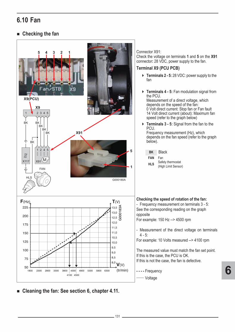
131
6
6.10 Fan
� Checking the fan
� Cleaning the fan: See section 6, chapter 4.11.
Connector X91:Check the voltage on terminals 1 and 5 on the X91connector: 28 VDC, power supply to the fan.Terminal X9 (PCU PCB)
� Terminals 2 - 5: 28 VDC: power supply to the fan
� Terminals 4 - 5: Fan modulation signal from the PCU.Measurement of a direct voltage, which depends on the speed of the fan:0 Volt direct current: Stop fan or Fan fault14 Volt direct current (about): Maximum fan speed (refer to the graph below)
� Terminals 3 - 5: Signal from the fan to the PCU.Frequency measurement (Hz), which depends on the fan speed (refer to the graph below).
Checking the speed of rotation of the fan:- Frequency measurement on terminals 3 - 5:See the corresponding reading on the graph oppositeFor example: 150 Hz --> 4500 rpm
- Measurement of the direct voltage on terminals4 - 5:
For example: 10 Volts measured --> 4100 rpm
The measured value must match the fan set point.If this is the case, the PCU is OK.If this is not the case, the fan is defective.
- - - - Frequency____ Voltage
HLS
X9
X9(PCU)
2 3 4 5
X91
BKBK
BK
BK
1 2 4 5
FAN
1
BK
BK1
2
X117
X91
12345
G000180A
5
1
BK BlackFAN Fan
HLS Safety thermostat(High Limit Sensor)
(tr/min)
F(Hz) T(V)
V(V)
G00
0183
A
50
8,0
8,5
9,0
9,5
10,0
10,5
11,0
11,5
12,0
12,5
13,0
13,5
1800 2300 2800 3300 3800 4300
4100 4500
4800 5300 5800 6300
75
100
125
150
175
200
225

132
6
6.11 Safety thermostat (HLS)
� Check the ohmic value of the safety thermostat after disconnecting the connector:- 0 to 1 Ohm: Safety thermostat (HLS) OK- If resistance infinite: Safety thermostat
(HLS) open, or safety thermostat defective.
Terminal X9 (on PCU board)
Terminals 1 - 2: - Measurement when switched off: 0 to 1
Ohm: Safety thermostat (HLS) + cable form: OK
- If resistance infinite: Safety thermostat (HLS) open, or Safety thermostat or harness defective.
0,9 Ω
G000143
HLS
X92 3 4 5
X91
BKBK
BK
BK
1 2 4 5
FAN
1
BK
BK1
2
X117
12
X9(PCU)
G000195BK Black
FAN Fan
HLS Safety thermostat(High Limit Sensor)

133
6
6.12 Connecting the PCU PCB to IN BLFor example: Flue gas thermostat (Option - packageHR43 or HR53)The flue gas thermostat is connected to the X12connector on the PCU board, to the input marked INBL
� Measurement of the ohmic value of the flue gas thermostat: disconnect the connector on the X12 terminal block on the PCU boardThe measured value is approximately 63 Ohm
In case of BL OPEN FAIL fault:� Check the device connected to the ENT BL
contact: If it is a flue gas thermostat: check the chimney, clean the heat exchanger
� Press the � key to clear the fault� If the fault is not cleared: install a bridge on
the ENT BL contact and then clear the fault.� If the fault is no longer displayed: the TF or
the component which was connected to ENT BL is defective; replace it.
� If the fault is not cleared: Defective PCU PCB
T001
634-
A
G000
192A
2 1
PCU
X12

134
6
7. Specific maintenance operations7.1 Replacing the reversal valve
�Before any operation, ensure that:- The mains supply is disconnected,- The gas supply is shut off,- The boiler is hydraulically isolated and drained.
� During inspection and maintenance operations, always replace allgaskets on the parts removed.
If replacement is necessary, proceed as follows:
1. Close the main water valve2. Drain the boiler3. Remove the air vent hose above the siphon4. Remove the siphon5. Remove the clip holding the heating return hose in place on the right
side of the hydrobloc6. Remove the heating return hose on the right side of the hydrobloc and
not on the heat exchanger side (heating circuit).7. Remove the connector on the reversal valve8. Remove the clip holding the reversal valve in place9. Remove the reversal valve: Lift and rotate by a quarter turn10. Reassembly: Proceed as for dismantling in reverse
�Caution: Pay attention to the positioning cams on the reversal valve.
T002639-C
3
4
5
6
21
7
8
9
1
2
10
1 2

135
6
7.2 Replacing the flue gas non-return valve
� Replace the nonreturn valve when faulty or when the maintenance kitcontains one.
To do this, proceed as follows:1. Remove the air inlet flue on the venturi. 2. Unscrew the top connection on the gas valve unit.3. Disconnect the connector located under the fan. 4. Release the 2 clips holding the fan/mixing elbow unit in place on the
heat exchanger.5. Completely remove the fan/mixing elbow unit.6. Replace the non-return valve located between the mixing elbow and
the fan.
�Observe the assembly sequence.7. Reassembly: Proceed as for dismantling in reverse (Replace the
seals).
T002517-B
2x
6
2
X91
3
1
4
2x
5

136
6
7.3 Replacing the gas valve
�Before any operation, ensure that:- The mains supply is disconnected,- The gas supply is shut off.
1. Close the main gas inlet valve2. Close the gas valve of the boiler.3. Cut the power supply to the boiler.4. Disconnect the connectors5. Unscrew the fittings on the gas valve. 6. Install the new gas valve with the new gaskets and connect the wiring
harness.7. Check the leak tightness of the connections.8. Check the settings according to the gas type: See section 6, chapter
8.
G000173
G000197

137
6
7.4 Replacing the boiler tanks (MCA 25/28 BIC)
� Replace the boiler tanks when they are defectiveTo do this, proceed as follows:1. Close the main water valve. Drain the boiler.2. Remove the air vent hose above the siphon.3. Remove the siphon.4. Remove the clip holding the plug in place.5. Remove the plug. 6. Open the drainage valve on the tank hydrobloc to drain the boiler
tanks.7. Unscrew the connection on the domestic hot water outlet8. Unscrew the connection on the pipe that links the hydrobloc to the
boiler tanks.9. Remove the pipes connected to the boiler tanks.10. Pull out the DHW sensor11. Remove the cord holding the control panel in place.12. Unscrew the 4 screws located on the front and back of the boiler tanks.13. Remove the boiler tanks with the left-hand section of the insulation.14. Follow in reverse order for re-assembly.
T001903-D
2
3
H2O
6
1
87
4x
9
12
13
10
11
4
5

138
6
8. Gas settings / Adapting to another gas type (with new gas valve version)
� France: The boiler is preset in the factory to operate on natural gas H (G20).
Gas valve, Reference: S101507 - Type: HONEYWELL VK4115V E1311
A. Setting at PMAX
B. Setting at PMIN
Operations required to operate on a different gas type:1. For propane only (For all models except MCA_35): installation of a diaphragm - See section 8.1.2. Setting the air/gas ratio (Full load / Part load): see chapters 8.2 and 8.33. Setting of the fan speed: See section 10.
�Only a qualified engineer may carry out the following operations.For Belgium: The operations required to adapt from one gas to another must becarried out by a Serv’Elite technician.
A
G000132
B

139
6
8.1 Installation / Checking the gas diaphragm (with new gas valveversion)
� All countries except: Belgium, Poland
(1) Model available only in the following countries: Italy, Slovenia.
� Belgium
� Poland
Gas typeDiameter of the gas diaphragm
MCA 10(1) MCA 15 MCA 25 MCA 25/28 MI MCA 25/28 BIC MCA 35Propane (G31) 3.00 3.00 4.00 4.00 4.00 -
Gas typeDiameter of the gas diaphragm
MCA 15 BE MCA 25 BE MCA 25/28 MI BE MCA 35 BE MCA 35/40 MI BEPropane (G31) 3.00 4.00 4.00 - -
Gas typeDiameter of the gas diaphragm
MCA 15 PL MCA 25 PL MCA 25/28 MI PL MCA 25/28 BIC PL MCA 35 PLPropane (G31) 3.00 3.00 4.00 4.00 -
T001569-A
X.XX

140
6
8.2 Setting the air/gas ratio (Full load / Part load)(with new gas valve version)
� If an automatic vent cycle is running, it is not possible to perform these operations.
1. Unscrew the plug of the flue gas measurement point. 2. Connect the flue gas analyser.
� Ensure that the opening around the sensor is completely sealed whentaking measurements.
3. In the main display, press key �.The menu EMISSION MEASURMENTS is displayed on thescreen.
4. Select the generator desired. The characteristics of the generatorare displayed.
T001581-A
1
1
2
2
��
STD� � �
�
0 2 4 6 8 10 12 14 16 18 22 2420
�� AUTO� � ���
SUNDAY 11:45
TEMP.: 68°
C002271-F-04
bar
1
1
2
2
��
STD� � �
�
0 2 4 6 8 10 12 14 16 18 22 2420
�� AUTO� �� ��
EMISSION MESURMENTSGENERATOR : GENE �
C002346-E-04

141
6
� Repeat the high speed test and the low speed test as often as necessary until the correct values are obtained without havingto make additional adjustments.
5. Full load:Turn the rotary button until PMAX is displayed.
� The display GENE : OFF signifies normal operation.6. Measure the percentage of O2 or CO2 in the flue gases (Front
panel removed).
� Setting values: See following chapter.
7. If this rate does not match the required value, correct the gas/airratio using the adjustment screw A on the gas valve unit. The screw A is a worm screw, which adjusts the restrictor A’.Depending on the position of the restrictor A', the O2 or CO2 leveldecreases or increases.
� For more detailed information, see chapter: 8.4 Basic setting for thegas/air ratio.
8. Check the flame through the flame inspection window: The flamemust not be detached.
9. Part load: Turn the rotary button until PMIN is displayed.10. Measure the percentage of O2 or CO2 in the flue gases (Front
panel removed).11. If this rate does not match the required value, correct the gas/air
ratio using the adjustment screw B on the gas valve unit.
� Setting values: See following chapter
�Turn the screw B anticlockwise to obtain a lower CO2 value.�Turn the screw B clockwise to obtain a higher CO2 value.
12. Check the flame through the flame inspection window: The flamemust be stable and blue in colour with orange particles around theedge of the burner.
bar
1
1
2
2
��
STD� � �
�
0 2 4 6 8 10 12 14 16 18 22 2420
�� AUTO� �� ��
GENE :BOILER TEMP.CURRENTFAILURE
PMAX68°C10µA
5600 tr/min �
C002347-E-04
OFF => PMAX
A
A’G
0002
35
bar
1
1
2
2
��
STD� � �
�
0 2 4 6 8 10 12 14 16 18 22 2420
�� AUTO� �� ��
GENE :BOILER TEMP.CURRENTFAILURE
PMIN68°C10µA
1850 tr/min �
C002348-E-04
OFF => PMIN
B
T000933-B
B

142
6
8.3 O2/CO2 checking and setting value (with new gas valve version)� Gas H (G20) - All countries except Belgium
� Gas H (G20 BE) - For Belgium
Gas H - At full load (at high speed)
Boiler typeSetting value Checking value
O2 (%) CO2 (%) O2 (%) CO2 (%)
All countries except:
Switzerland, Austria, Belgium
MCA 10(1) - MCA 15 (PL) - MCA 25 (PL) MCA 25/28 MI (PL) - MCA 25/28 BIC (PL)
5.2 ± 0.4 8.8 ± 0.2 5.2 ± 0.5 8.8 ± 0.3
MCA 35 (PL) 4.8 ± 0.4 9.0 ± 0.2 4.8 ± 0.5 9.0 ± 0.3
SwitzerlandMCA 25 5.9 ± 0.4 8.4 ± 0.2 5.9 ± 0.5 8.4 ± 0.3MCA 35 5.7 ± 0.4 8.5 ± 0.2 5.7 ± 0.5 8.5 ± 0.3
Austria MCA 25 - MCA 35 5.7 ± 0.4 8.5 ± 0.2 5.7 ± 0.5 8.5 ± 0.3
Gas H - at low speed
Boiler typeSetting value Checking value
O2 (%) CO2 (%) O2 (%) CO2 (%)
All countries except:
Switzerland,Austria, Belgium
MCA 10(1) - MCA 15 (PL) - MCA 25 (PL) MCA 25/28 MI (PL) - MCA 25/28 BIC (PL)
5.9 ± 0.4 8.4 ± 0.2 5.9 ± 0.4 8.4 ± 0.2
MCA 35 (PL) 5.5 ± 0.4 8.6 ± 0.2 5.5 ± 0.4 8.6 ± 0.2
SwitzerlandMCA 25 6.6± 0.4 8.0 ± 0.2 6.6 ± 0.5 8.0 ± 0.3MCA 35 6.4 ± 0.4 8.1 ± 0.2 6.4 ± 0.5 8.1 ± 0.3
Austria MCA 25 - MCA 35 6.4 ± 0.4 8.1 ± 0.2 6.4 ± 0.5 8.1 ± 0.3
Gas H - At full load (at high speed)
Boiler typeSetting value Checking value
O2 (%) CO2 (%) O2 (%) CO2 (%)
MCA 15 BE 5.2 ± 0.4 8.8 ± 0.2 5.2 ± 0.5 8.8 ± 0.3MCA 25 BE - MCA 25/28 MI BE 4.3 ± 0.4 9.3 ± 0.2 4.3 ± 0.5 9.3 ± 0.3MCA 35 BE - MCA 35/40 MI BE 4.4 ± 0.4 9.25 ± 0.2 4.4 ± 0.5 9.25 ± 0.3
Gas H - at low speed
Boiler typeSetting value Checking value
O2 (%) CO2 (%) O2 (%) CO2 (%)
MCA 15 BE 5.9 ± 0.4 8.4 ± 0.2 5.9 ± 0.4 8.4 ± 0.2MCA 25 BE - MCA 25/28 MI BE 5.0 ± 0.4 8.9 ± 0.2 5.0 ± 0.4 8.9 ± 0.2
35 BE - MCA 35/40 MI BE 5.1 ± 0.4 8.85 ± 0.2 5.1 ± 0.4 8.85 ± 0.2

143
6
� Gas L (G25) - All countries except Belgium
� Gas L (G25 BE) - For Belgium
� Propane (G31) - All countries
Gas L - At full load (at high speed)
Boiler typeSetting value Checking value
O2 (%) CO2 (%) O2 (%) CO2 (%)
MCA 15 - MCA 25 - MCA 25/28 MI MCA 25/28 BIC 4.9 ± 0.4 8.8 ± 0.2 4.9 ± 0.5 8.8 ± 0.3
35 4.6 ± 0.4 9.0 ± 0.2 4.6 ± 0.5 9.0 ± 0.3
Gas L - at low speed
Boiler typeSetting value Checking value
O2 (%) CO2 (%) O2 (%) CO2 (%)
MCA 15 - MCA 25MCA 25/28 MI - MCA 25/28 BIC 5.6 ± 0.4 8.4 ± 0.2 5.6 ± 0.4 8.4 ± 0.2
35 5.3 ± 0.4 8.6 ± 0.2 5.3 ± 0.4 8.6 ± 0.2
Gas L - At full load (at high speed)
Boiler typeSetting value Checking value
O2 (%) CO2 (%) O2 (%) CO2 (%)
MCA 15 BE 8.6 ± 0.4 6.8 ± 0.2 8.6 ± 0.5 6.8 ± 0.3MCA 25 BE - MCA 25/28 MI BE 7.9 ± 0.4 7.2 ± 0.2 7.9 ± 0.5 7.2 ± 0.3
MCA 35 BE 6.8 ± 0.4 7.75 ± 0.2 6.8 ± 0.5 7.75 ± 0.3
Gas L - at low speed
Boiler typeSetting value Checking value
O2 (%) CO2 (%) O2 (%) CO2 (%)
MCA 15 BE 9.3 ± 0.4 6.4 ± 0.2 9.3 ± 0.4 6.4 ± 0.2MCA 25 BE 8.6 ± 0.4 6.8 ± 0.2 8.6 ± 0.4 6.8 ± 0.2
MCA 25/28 MI BE 8.3 ± 0.4 6.9 ± 0.2 8.3 ± 0.4 6.9 ± 0.2MCA 35 BE 7.5 ± 0.4 7.35 ± 0.2 7.5 ± 0.4 7.35 ± 0.2
Propane - At full load (at high speed)
Boiler typeSetting value Checking value
O2 (%) CO2 (%) O2 (%) CO2 (%)
MCA 10(1) - MCA 15 (BE / PL) - MCA 25 (BE / PL)MCA 35 (BE / PL)
MCA 25/28 MI (BE / PL) - MCA 25/28 BIC (BE / PL)5.2 ± 0.3 10.3 ± 0.2 5.2 ± 0.5 10.3 ± 0.3
Propane - at low speed
Boiler typeSetting value Checking value
O2 (%) CO2 (%) O2 (%) CO2 (%)
MCA 10(1) - MCA 15 (BE / PL) - MCA 25 (BE / PL)MCA 35 (BE / PL)
MCA 25/28 MI (BE / PL) - MCA 25/28 BIC (BE / PL)5.8 ± 0.3 9.9 ± 0.2 5.8 ± 0.3 9.9 ± 0.2

144
6
� For Italy: Propane air (G230)
(1) Model available only in the following countries: Italy, Slovenia.* Except for: Switzerland, Austria.
� For Poland: Gas Lw(G27)
� For Poland: Gas Ls (G2.350)
Propane air - At full load (at high speed)
Boiler typeSetting value Checking value
O2 (%) CO2 (%) O2 (%) CO2 (%)
MCA 10(1) - MCA 15 - MCA 25MCA 25/28 MI - MCA 25/28 BIC
MCA 354.4 ± 0.3 10.2 ± 0.2 4.4 ± 0.5 10.2 ± 0.3
Propane air - at low speed
Boiler typeSetting value Checking value
O2 (%) CO2 (%) O2 (%) CO2 (%)
MCA 10(1) - MCA 15 - MCA 25MCA 25/28 MI - MCA 25/28 BIC
MCA 355.1 ± 0.3 9.8 ± 0.2 5.1 ± 0.3 9.8 ± 0.2
Gas Lw - At full load (at high speed)
Boiler typeSetting value Checking value
O2 (%) CO2 (%) O2 (%) CO2 (%)
MCA 15 PL - MCA 25 PLMCA 25/28 MI PL- MCA 25/28 BIC PL 4.8 ± 0.4 8.8 ± 0.2 4.8 ± 0.6 8.8 ± 0.3
MCA 35 PL 4.6 ± 0.4 8.9 ± 0.2 4.6 ± 0.6 8.9 ± 0.3
Gas Lw - at low speed
Boiler typeSetting value Checking value
O2 (%) CO2 (%) O2 (%) CO2 (%)
MCA 15 PL - MCA 25 PLMCA 25/28 MI PL - MCA 25/28 BIC PL 5.5 ± 0.4 8.4± 0.2 5.5 ± 0.4 8.4± 0.2
MCA 35 PL 5.3 ± 0.4 8.5 ± 0.2 5.3 ± 0.4 8.5 ± 0.2
Gas Ls - At full load (at high speed)
Boiler typeSetting value Checking value
O2 (%) CO2 (%) O2 (%) CO2 (%)
MCA 15 PL - MCA 25 PLMCA 25/28 MI PL - MCA 25/28 BIC PL 5.1 ± 0.4 8.5 ± 0.2 5.1 ± 0.6 8.5 ± 0.3
MCA 35 PL not released
Gas Ls - at low speed
Boiler typeSetting value Checking value
O2 (%) CO2 (%) O2 (%) CO2 (%)
MCA 15 PL - MCA 25 PLMCA 25/28 MI PL - MCA 25/28 BIC PL 5.9 ± 0.4 8.1 ± 0.2 5.9 ± 0.4 8.1 ± 0.2
MCA 35 PL not released

145
6
8.4 Basic setting for the gas/air ratioIf the gas/air ratio is out of adjustment, the gas valve unit has a basic setting. To go back to the basic setting, proceed as follows:
�Before any operation, ensure that:- The mains supply is disconnected,- The gas supply is shut off,- The boiler is hydraulically isolated and drained.
1. Remove the air inlet flue on the venturi (Silencer)2. Unscrew the top connection on the gas valve unit.3. Disconnect the connector located under the fan (Connector X91).4. Release the 2 clips holding the fan/mixing elbow unit in place on the
heat exchanger. 5. Completely remove the fan/mixing elbow unit. Tilt the burner and
remove it, along with the heat exchanger gasket.
6. Turn the setting screw A on the gas valve unit to set the restrictor A’ tothe position shown in the illustration opposite:Turning the screw A clockwise causes the restrictor A’ to rotate clockwise and vice versa.
7. Turn the setting screw B on the gas valve unit anti-clockwise until it isflush with the front (see illustration).
8. Turn the setting screw B on the gas valve unit by 6 turns clockwise.9. Follow the procedure in reverse to re-assemble all of the components.
Replace the seals.
2
X91
3
G000199
1
4
2x
5
B
G00
0200
A
A’6
7 8

146
6
9. Gas settings / Adapting to another gas type (with old gas valve)
� France: The boiler is preset in the factory to operate on natural gas H (G20).
Gas valve, Reference: S100887 - Type: HONEYWELL VK4115V E1054
B. Setting at PMIN
Operations required to operate on a different gas type:1. Check on the diaphragm diameter for the gas type: See section 9.12. Setting the air/gas ratio (Full load / Part load): see chapters 9.1 and 9.23. Setting of the fan speed: See section 10.
�Only a qualified engineer may carry out the following operations.For Belgium: The operations required to adapt from one gas to another must becarried out by a Serv’Elite technician.
B
G000
147

147
6
9.1 Checking the gas diaphragm (with old gas valve)
� All countries except: Belgium, Poland
(1) Model available only in the following countries: Italy, Slovenia.* Factory setting(**) Old version, cannot be converted to propane
� Belgium
* Factory setting(**) Old version, cannot be converted to propane
� Poland
* Factory setting(**) Old version, cannot be converted to propane
Gas typeDiameter of the gas diaphragm
MCA 10(1) MCA 15 MCA 25 MCA 25/28 MI MCA 25/28 BIC MCA 35Gas H (G20) 3.70* 3.70* 4.95* 4.95* 4.95* 5.40*Gas L (G25) 4.40 4.40 5.80 5.80 5.80 6.05Propane (G31) 2.85 2.85 3.80 3.80 3.80 (**)Propane air (G230)(Italy) 4.40 4.40 5.80 5.80 5.80 6.15
Gas typeDiameter of the gas diaphragm
MCA 15 BE MCA 25 BE MCA 25/28 MI BE MCA 35 BE MCA 35/40 MI BEGas H (G20) 3.70* 5.10* 5.10* 5.40* 5.40*Gas L (G25) 3.70 5.10 5.10 5.40 5.40Propane (G31) 2.85 3.80 3.80 4.10 (**) 4.10 (**)
Gas typeDiameter of the gas diaphragm
MCA 15 PL MCA 25 PL MCA 25/28 MI PL MCA 25/28 BIC PL MCA 35 PLGas H (G20) 3.70* 4.95* 4.95* - 5.40*Gas Lw (G27) 4.70 6.05 6.05 - 7.00Gas Ls (G2.350) 5.80 7.90 7.90 - 8.80Propane (G31) 2.85 3.80 3.80 - 4.10 (**)
T001569-A
X.XX

148
6
9.2 Setting the air/gas ratio (Full load / Part load, with old gas valve)
� If an automatic vent cycle is running, it is not possible to perform these operations.
1. Unscrew the plug of the flue gas measurement point. 2. Connect the flue gas analyser.
� Ensure that the opening around the sensor is completely sealed whentaking measurements.
3. In the main display, press key �.The menu EMISSION MEASURMENTS is displayed on thescreen.
4. Select the generator desired. The characteristics of the generatorare displayed.
T001581-A
1
1
2
2
��
STD� � �
�
0 2 4 6 8 10 12 14 16 18 22 2420
�� AUTO� � ���
SUNDAY 11:45
TEMP.: 68°
C002271-F-04
bar
1
1
2
2
��
STD� � �
�
0 2 4 6 8 10 12 14 16 18 22 2420
�� AUTO� �� ��
EMISSION MESURMENTSGENERATOR : GENE �
C002346-E-04

149
6
� Repeat the high speed test and the low speed test as often as necessary until the correct values are obtained without havingto make additional adjustments.
5. Full load:Turn the rotary button until PMAX is displayed. Theboiler runs at maximum output
6. Measure the percentage of O2 or CO2 in the flue gases (Frontpanel removed).
7. Compare the values measured with the checking values given inthe table. See following chapter: 9.3 O2/CO2 checking and settingvalue (with old gas valve). When the values measured fall outsidethe limits of the set point values:
- Check that the diameter allowed for the diaphragm in thegas valve is suitable for the boiler and the gas type used
- Check that the gas diaphragm is not clogged- Check the supply pressure
� No adjustment in output PMAX is possible on the old gas valve.8. Check the flame through the flame inspection window: The flame
must not be detached.
9. Part load: Turn the rotary button until PMIN is displayed.10. Measure the percentage of O2 or CO2 in the flue gases (Front
panel removed).11. If this rate does not match the required value, correct the gas/air
ratio using the adjustment screw B on the gas valve unit.
� See following chapter: 9.3 O2/CO2 checking and setting value(with old gas valve)
�Turn the screw B anticlockwise to obtain a lower CO2 value.�Turn the screw B clockwise to obtain a higher CO2 value.
12. Check the flame through the flame inspection window: The flamemust be stable and blue in colour with orange particles around theedge of the burner.
bar
1
1
2
2
��
STD� � �
�
0 2 4 6 8 10 12 14 16 18 22 2420
�� AUTO� �� ��
GENE :BOILER TEMP.CURRENTFAILURE
PMAX68°C10µA
5600 tr/min �
C002347-E-04
OFF => PMAX
T001569-A
X.XX
bar
1
1
2
2
��
STD� � �
�
0 2 4 6 8 10 12 14 16 18 22 2420
�� AUTO� �� ��
GENE :BOILER TEMP.CURRENTFAILURE
PMIN68°C10µA
1850 tr/min �
C002348-E-04
OFF => PMIN
T001579-B
B
B

150
6
9.3 O2/CO2 checking and setting value (with old gas valve)• Gas H (G20) - All countries except Belgium
• Gas L (G25) - All countries except Belgium
• Gas H (G20) - For Belgium
Gas H (G20) - At full load (at high speed)
Boiler typeChecking value
O2 (%) CO2 (%)
MCA 10(1) - MCA 15 (PL) - MCA 25 (PL) MCA 25/28 MI (PL) - MCA 25/28 BIC (PL)
5.2 ± 1.0 8.8 ± 0.5
35 (PL) 4.8 ± 1.0 9.0 ± 0.5
Italie : MCA 10(1) - MCA 15 - MCA 25 - MCA 25/28 MI 5.9 ± 1.0 8.4 ± 0.5
Gas H (G20) - at low speed
Boiler typeSetting value Checking value
O2 (%) CO2 (%) O2 (%) CO2 (%)
MCA 10(1) - MCA 15 (PL) - MCA 25 (PL) MCA 25/28 MI (PL) - MCA 25/28 BIC (PL)
5.9 ± 0.3 8.4 ± 0.2 5.9 ± 1.0 8.4 ± 0.5
35 (PL) 5.6 ± 0.3 8.6 ± 0.2 5.6 ± 1.0 8.6 ± 0.5
Gas L (G25) - At full load (at high speed)
Boiler typeChecking value
O2 (%) CO2 (%)
MCA 15 - MCA 25 - MCA 25/28 MI MCA 25/28 BIC 4.9 ± 1.0 8.8 ± 0.5
35 4.6 ± 1.0 9.0 ± 0.5
Gas L (G25) - at low speed
Boiler typeSetting value Checking value
O2 (%) CO2 (%) O2 (%) CO2 (%)
MCA 15 - MCA 25 - MCA 25/28 MI 5.7 ± 0.3 8.4 ± 0.2 5.7 ± 1.0 8.4 ± 0.5MCA 25/28 BIC 5.9 ± 0.3 8.4 ± 0.2 5.9 ± 1.0 8.4 ± 0.5
35 5.3 ± 0.3 8.6 ± 0.2 5.3 ± 1.0 8.6 ± 0.5
Gas H (G20) - At full load (at high speed)
Boiler typeChecking value
O2 (%) CO2 (%)
MCA 15 BE 5.2 ± 1.0 8.8 ± 0.5MCA 25 BE - MCA 25/28 MI BE 4.3 ± 1.0 9.3 ± 0.5
35 BE - MCA 35/40 MI BE 4.8 ± 1.0 9.0 ± 0.5
Gas H (G20) - at low speed
Boiler typeSetting value Checking value
O2 (%) CO2 (%) O2 (%) CO2 (%)
MCA 15 BE 5.9 ± 0.3 8.4 ± 0.2 5.9 ± 1.0 8.4 ± 0.5MCA 25 BE - MCA 25/28 MI BE 5.0 ± 0.3 8.9 ± 0.2 5.0 ± 1.0 8.9 ± 0.5
35 BE - MCA 35/40 MI BE 5.6 ± 0.3 8.6 ± 0.2 5.6 ± 0.1 8.6 ± 0.5

151
6
• Gas L (G25 BE) - For Belgium
• Propane (G31) - All countries
• For Italy: Propane air (G230)
(1) Model available only in the following countries: Italy, Slovenia.
Gas L (G25) - At full load (at high speed)
Boiler typeChecking value
O2 (%) CO2 (%)
MCA 15 BE 8.6 ± 1.0 6.8 ± 0.5MCA 25 BE - MCA 25/28 MI BE 7.9 ± 1.0 7.2 ± 0.5
35 BE - MCA 35/40 MI BE 8.4 ± 1.0 6.9 ± 0.5
Gas L (G25) - at low speed
Boiler typeSetting value Checking value
O2 (%) CO2 (%) O2 (%) CO2 (%)
MCA 15 BE 8.8 ± 0.3 6.7 ± 0.2 8.8 ± 1.0 6.7 ± 0.5MCA 25 BE 8.2 ± 0.3 7.0 ± 0.2 8.2 ± 1.0 7.0 ± 0.5
MCA 25/28 MI BE 8.2 ± 0.3 7.0 ± 0.2 8.2 ± 1.0 7.0 ± 0.535 BE - MCA 35/40 MI BE 8.7 ± 0.3 6.8 ± 0.2 8.7 ± 1.0 6.8 ± 0.5
Propane - At full load (at high speed)
Boiler typeChecking value
O2 (%) CO2 (%)
MCA 10(1) - MCA 15 (BE / PL) - MCA 25 (BE / PL)MCA 25/28 MI (BE / PL) - MCA 25/28 BIC (PL)
5.2 ± 1.0 10.3 ± 0.5
France, be : MCA 15 - MCA 25 - MCA 25/28 - MI CA 25/28 BIC 5.2 ± 1.0 10.3 ± 0.5
Propane - at low speed
Boiler typeSetting value Checking value
O2 (%) CO2 (%) O2 (%) CO2 (%)
MCA 10(1) - MCA 15 (BE / PL) - MCA 25 (BE / PL)MCA 25/28 MI (BE / PL) - MCA 25/28 BIC (BE / PL)
5.7 ± 0.3 10.0 ± 0.2 5.7 ± 1.0 10.0 ± 0.5
FR, BE, Italie : MCA 10(1) - MCA 15 - MCA 25 - MCA 25/28 MI - MCA 25/28 BIC
5.8 ± 0.3 9.9 ± 0.2 5.8 ± 1.0 9.9 ± 0.5
Propane air - At full load (at high speed)
Boiler typeChecking value
O2 (%) CO2 (%)
MCA 10(1) - MCA 15 - MCA 25MCA 25/28 MI - MCA 25/28 BIC
MCA 354.4 ± 1.0 10.2 ± 0.5
Propane air - at low speed
Boiler typeSetting value Checking value
O2 (%) CO2 (%) O2 (%) CO2 (%)
MCA 10(1) - MCA 15 - MCA 25MCA 25/28 MI - MCA 25/28 BIC
MCA 355.0 ± 0.3 9.8 ± 0.2 5.0 ± 1.0 9.8 ± 0.5

152
6
• For Poland: Gas Lw (G27)
• For Poland: Gas Ls (G2.350)
Gas Lw - At full load (at high speed)
Boiler typeSetting value Checking value
O2 (%) CO2 (%) O2 (%) CO2 (%)
MCA 15 PL - MCA 25 PLMCA 25/28 MI PL- MCA 25/28 BIC PL 4.8 ± 0.4 8.8 ± 0.2 4.8 ± 0.6 8.8 ± 0.3
MCA 35 PL 4.6 ± 0.4 8.9 ± 0.2 4.6 ± 0.6 8.9 ± 0.3
Gas Lw - at low speed
Boiler typeSetting value Checking value
O2 (%) CO2 (%) O2 (%) CO2 (%)
MCA 15 PL - MCA 25 PLMCA 25/28 MI PL - MCA 25/28 BIC PL 5.5 ± 0.4 8.4± 0.2 5.5 ± 0.4 8.4± 0.2
MCA 35 PL 5.3 ± 0.4 8.5 ± 0.2 5.3 ± 0.4 8.5 ± 0.2
Gas Ls - At full load (at high speed)
Boiler typeSetting value Checking value
O2 (%) CO2 (%) O2 (%) CO2 (%)
MCA 15 PL - MCA 25 PLMCA 25/28 MI PL - MCA 25/28 BIC PL 5.1 ± 0.4 8.5 ± 0.2 5.1 ± 0.6 8.5 ± 0.3
MCA 35 PL not released
Gas Ls - at low speed
Boiler typeSetting value Checking value
O2 (%) CO2 (%) O2 (%) CO2 (%)
MCA 15 PL - MCA 25 PLMCA 25/28 MI PL - MCA 25/28 BIC PL 5.9 ± 0.4 8.1 ± 0.2 5.9 ± 0.4 8.1 ± 0.2
MCA 35 PL not released

153
6
10.Setting the fan speeds in accordance with the gastype
� The fan speed settings are identical, regardless of the gas valve type (Previous version / New version).� Set the parameter INSTALLATION to EXTENDED� To set the following parameters:
- MIN.VENT.,- MAX.VENT.BOIL,- MAX.VENT.DHW,- START SP..
� Recommended Settings - All countries except: Belgium, Poland
(1) Model available only in the following countries: Italy, Slovenia.* Factory setting
Gas type Parameter Unit MCA 10(1) MCA 15 MCA 25 MCA 25/28 MI
Gas H (G20) MIN.VENT. rpm 1800* 1800* 1800* 1800*MAX.VENT.BOIL rpm 3300* 4500* 5600* 4600*MAX.VENT.DHW rpm 3300* 4500* 5600* 6200*START SP. rpm 3300* 3700* 3000* 3000*
Gas L (G25) MIN.VENT. rpm 1800 1800 1800 1800MAX.VENT.BOIL rpm 3200 4400 5300 4300MAX.VENT.DHW rpm 3200 4400 5300 5900START SP. rpm 3200 3700 3000 3000
Propane (G31) MIN.VENT. rpm 2200 2200 1800 1800MAX.VENT.BOIL rpm 3200 4400 5300 4300MAX.VENT.DHW rpm 3200 4400 5300 5900START SP. rpm 3200 3700 3000 3000
Propane air (G230)(Italy)
MIN.VENT. rpm 2100 2100 1800 1800MAX.VENT.BOIL rpm 3200 4200 4900 4100MAX.VENT.DHW rpm 3200 4200 4900 5400START SP. rpm 3200 3700 3000 3000
All types of gas MAX.PUMP SPEED % 60* 60* 60* 60*MIN.PUMP SPEED % 20* 20* 20* 20*

154
6
� Recommended Settings - All countries except: Belgium, Poland
* Factory setting
� Recommended Settings - Belgium
* Factory setting
Gas type Parameter Unit MCA 25/28 BIC MCA 35Gas H (G20) MIN.VENT. rpm 1800* 1700*
MAX.VENT.BOIL rpm 4600* 6200*MAX.VENT.DHW rpm 6300* 6200*START SP. rpm 3000* 4000*
Gas L (G25) MIN.VENT. rpm 1800 1700MAX.VENT.BOIL rpm 4300 6200MAX.VENT.DHW rpm 5900 6200START SP. rpm 3000 4000
Propane (G31) MIN.VENT. rpm 1800 1700MAX.VENT.BOIL rpm 4300 6200MAX.VENT.DHW rpm 5900 6200START SP. rpm 3000 4000
Propane air (G230)(Italy)
MIN.VENT. rpm 1800 1700MAX.VENT.BOIL rpm 4100 6200MAX.VENT.DHW rpm 5400 6200START SP. rpm 3000 4000
All types of gas MAX.PUMP SPEED % 60* 60*MIN.PUMP SPEED % 20* 20*
Gas type Parameter Unit MCA 15 BE MCA 25 BE MCA 25/28 MI BE MCA 35 BEGas H (G20) MIN.VENT. rpm 1800* 1800* 1800* 1700*
MAX.VENT.BOIL rpm 4500* 5200* 4200* 6200*MAX.VENT.DHW rpm 4500* 5200* 5800* 6200*START SP. rpm 3700* 3000* 3000* 4000*
Gas L (G25) MIN.VENT. rpm 1800 1800 1800 1700MAX.VENT.BOIL rpm 4500 4200 4200 5400MAX.VENT.DHW rpm 4500 5800 5800 6800START SP. rpm 3700 3000 3000 4000
Propane (G31) MIN.VENT. rpm 2200 1800 1800 1700MAX.VENT.BOIL rpm 4400 5300 4300 6200MAX.VENT.DHW rpm 4400 5300 5900 6200START SP. rpm 3700 3000 3000 4000
All types of gas MAX.PUMP SPEED % 60* 60* 60* 60*MIN.PUMP SPEED % 20* 20* 20* 20*

155
6
� Recommended Settings - Poland
* Factory setting
Gas type Parameter Unit MCA 15 PL MCA 25 PL MCA 25/28 MI PLGas H (G20) MIN.VENT. rpm 1800* 1800* 1800*
MAX.VENT.BOIL rpm 4500* 5600* 4600*MAX.VENT.DHW rpm 4500* 5600* 6200*START SP. rpm 3700* 3000* 3000*
Gas Lw (G27)Gas Ls (G2.350)
MIN.VENT. rpm 1800 1800 1800MAX.VENT.BOIL rpm 4400 5300 4300MAX.VENT.DHW rpm 4400 5300 6000START SP. rpm 3700 3000 3000
Propane (G31) MIN.VENT. rpm 2200 1800 1800MAX.VENT.BOIL rpm 4400 5300 4300MAX.VENT.DHW rpm 4400 5300 5900START SP. rpm 3700 3000 3000
All types of gas MAX.PUMP SPEED % 60* 60* 60*MIN.PUMP SPEED % 20* 20* 20*
Gas type Parameter Unit MCA 25/28 BIC PL MCA 35 PLGas H (G20) MIN.VENT. rpm 1800* 1700*
MAX.VENT.BOIL rpm 4600* 6200*MAX.VENT.DHW rpm 6300* 6200*START SP. rpm 3000* 4000*
Gas Lw (G27)Gas Ls (G2.350)
MIN.VENT. rpm 1800 1700MAX.VENT.BOIL rpm 4300 6200MAX.VENT.DHW rpm 6000 6200START SP. rpm 3000 4000
Propane (G31) MIN.VENT. rpm 1800 1700MAX.VENT.BOIL rpm 4300 6200MAX.VENT.DHW rpm 5900 6200START SP. rpm 3000 4000
All types of gas MAX.PUMP SPEED % 60* 60*MIN.PUMP SPEED % 20* 20*

156
6

157
6

158
6

159
7
ELECTRICAL DIAGRAMS

160
7
Contents
1. Electrical diagram - For all models except MCA 25/28 BIC . . . . . . . . . . . . . . . . . . . . . . . . . 161
2. Electrical diagram - MCA 25/28 BIC . . . . . . . . . . . . . . . . . . . . . . . . . . . . . . . . . . . . . . . . . . . . 162

161
7
1. Electrical diagram - For all models except MCA 25/28 BIC
DISHMI DIEMATIC iSystem-display PCU PCU PCB
(Primary Control Unit)
DV Reversal valve (Direction Valve) PS Pressure sensor
(Pressure Switch)E Ignition/ionization electrode PSU Parameter storage for PCBs PCU and SU
(Parameter Storage Unit)FAN Fan
FS Flowmeter (Only ... MI version) (Flow Switch) PUMP A Boiler pump
FTS Boiler sensor(Flow Temperature Sensor)
PWMPUMP Pump modulation
GB Gas valve (Gas Block) P 230 V main supplyHLS Safety thermostat
(High Limit Sensor) RTS Return sensor (Return Temperature Sensor)
IT Ignition transformer(Ignition Transformer)
S On/Off switch (Switch)
SCU-C SCU PCB(Secondary Control Unit)
2 31K1
X1
X14X13 X12
X3X2 X4 X5
X6X7
X8X9
X10 X11
HLS
1 2 7 8 9 1 0
X123 4 5 6
X61 2 3
GN/YW
WHBL
GB
153
X21
X81 2 3
PUMP A
BRBL
GN/YW
3 1 2
X41
SCU-C
X111 2 3 4 5 6
WHGY
RDGN
YWOR
DV
X71 2 3
WHBK
RD
1 3 2
X121
IT
X52 3 4 1
E
BKBL
GN/YW
GY
1 23
X22
PWMPUMP
12 13
BKBK
1 2
X116
FTSRTS
9
RD
1
BK
1
2 2
X115
8
BL
1
22
X114
PS
10 11
BKBK
3 1
X112
FS
2 3
BKBK
1 3
X113
X104 5 7 6
X111
BKBK
BK
BK
1 2 3 4
PSU
X92 3 4 5
X91
BKBK
BK
BK
1 2 4 5
FAN
1
BK
BK1
2
X117
P230V, 50Hz
L N
SCU-C
X21 32
BL
BR
GN/YW
X11 23
BRBL
GN/YW
X34 3 2 15
BRBL
BRBL
GN/YW
3 1
4 2X51
S
DIS
PCU
HMI T001871
BK BlackBL BlueBR BrownGN Green
GN/YW Green / YellowGY GreyOR OrangeRD RedWH White YW Yellow

162
7
2. Electrical diagram - MCA 25/28 BIC
DISHMI DIEMATIC iSystem-display PS Pressure sensor
(Pressure Switch)
DV Reversal valve (Direction Valve) PSU Parameter storage for PCBs PCU and SU
(Parameter Storage Unit)E Ignition/ionization electrodeFAN Fan PUMP A Boiler pump
FTS Boiler sensor(Flow Temperature Sensor)
PUMP B DHW pumpPWMPUMP Pump modulationGB Gas valve (Gas Block)
HLS Safety thermostat(High Limit Sensor) S On/Off switch (Switch)
IT Ignition transformer(Ignition Transformer) RTS Return sensor
(Return Temperature Sensor)
P 230 V main supply SCU-C SCU PCB(Secondary Control Unit)
PCU PCU PCB(Primary Control Unit)
TS DHW sensor (Temperature Sensor)WS DHW sensor (Water Sensor)
2 31K1
X1
X14X13 X12
X3X2 X4 X5
X6X7
X8X9
X10 X11
1 2 7 8 9 1 0
X123 4 5 6
X61 2 3
GN/YW
WHBL
GB
153
X21
X81 2 3
PUMP A
WS
BRBL
GN/YW
X41
X41 2 3
BRBL
GN/YW
X81
SCU-C
X111 2 3 4 5 6
WHGY
ORRD
GN
YW
DV
X71 2 3
WHBK
RD
X121
IT
X52 3 4 1
E
BKBL
GN/YW
GY
1 23 3 211 23 1 23
X22
PWMPUMP
12 13
BKBK
1 2
X116
FTSRTS
9
RD
1
BK
1
2 2
X115
8
BL
1
22
X114
PS
10 11
BKBK
3 1
X112
TS
2
BK
1
X80
X104 5 7 6
X111
BKBK
BK
BK
1 2 3 4
PSU
X92 3 4 5
X91
BKBK
BK
BK
1 2 4 5
FAN
HLS
1
BK
BK1
2
X117
P230V, 50Hz
L N
SCU-C
X21 32
BL
BR
GN/YW
X14 23
BRBL
GN/YW
X34 3 2 15
BRBL
BRBL
GN/YW
3 1
4 2X51
S PUMP B
DISHMI
PCU
T001963-D
BK BlackBL BlueBR Brown
GN/YW Green / YellowGY GreyOR OrangeRD Red WH WhiteYW Yellow

163
7

© CopyrightIn the interest of customers, DE DIETRICH THERMIQUE are continuously endeavouring to make improvements in product quality. All thespecifications stated in this document are therefore subject to change without notice.
DE DIETRICH THERMIQUE � BP30 � 57 Rue de la Gare � F-67580 MERTZWILLERTel.: (+33) 3 88 80 27 00 � Fax: (+33) 3 88 80 27 99
www.dedietrich-thermique.com