Embed Size (px)
Citation preview

AFSM 100 STANDARD OPERATING PROCEDURES
Prepared by Systems Integration Support
Headquarters U.S. Postal Service
March 2002
AFSM 100 SOP
TABLE OF CONTENTS
TABLE OF CONTENTS ............................................................................................................................................2
AUTOMATED FLAT SORTING OPERATIONS POLICY ..................................................................................4
INTRODUCTION .......................................................................................................................................................6
PURPOSE..................................................................................................................................................................6 SCOPE.......................................................................................................................................................................7 BACKGROUND.......................................................................................................................................................7
RESPONSIBILITIES OF DIFFERENT MANAGEMENT LEVELS....................................................................7
HEADQUARTERS...................................................................................................................................................7 AREAS......................................................................................................................................................................8 DISTRICT .................................................................................................................................................................8 PROCESSING AND DISTRIBUTION CENTER / FACILITY...............................................................................9
AFSM 100 CHARACTERISTICS ...........................................................................................................................10
SAVINGS ...................................................................................................................................................................11
PROCESSING AND DISTRIBUTION CENTER/FACILITY OPERATIONS..................................................12
MANAGEMENT OPERATING DATA SYSTEM (MODS)..................................................................................14 PROCESSING PRIORITIES ..................................................................................................................................14 OPERATIONAL MAINTENANCE .......................................................................................................................16
AFSM 100 OPERATORS .........................................................................................................................................18
STAFFING..............................................................................................................................................................18 TRAINING..............................................................................................................................................................18
VIDEO CODING SYSTEM (VCS)..........................................................................................................................19
DATA CONVERSION OPERATORS (DCOS) ......................................................................................................20 DCO TRAINING.....................................................................................................................................................21
RECIRCULATION...................................................................................................................................................22
MAIL PREPARATION ............................................................................................................................................23
ATTACHMENT 1 .....................................................................................................................................................24
AFSM 100 AREA COORDINATORS....................................................................................................................24
ATTACHMENT 2 .....................................................................................................................................................25
EXAMPLE OF COST MODEL...............................................................................................................................25
ATTACHMENT 3 .....................................................................................................................................................26
OPERATIONAL TIPS ............................................................................................................................................26
ATTACHMENT 4 .....................................................................................................................................................31
PROCESSING PRIORITY CHART.......................................................................................................................31
2 March 2002

AFSM 100 SOP
ATTACHMENT 5 .....................................................................................................................................................32
AFSM 100 MACHINE SWEEP DOWN PROCEDURES......................................................................................32
ATTACHMENT 6 .....................................................................................................................................................36
TRAINING COURSES ...........................................................................................................................................36
ATTACHMENT 7 .....................................................................................................................................................37
EXAMPLE OF OUTPUT FROM VCS STAFFING MODEL................................................................................37
3 March 2002

AFSM 100 SOP
Automated Flat Sorting Operations Policy Processing Operations
MANAGERS, OPERATIONS SUPPORT (AREAS)
Automated Flat Sorting Operations The introduction of the Automated Flat Sorting Machine (AFSM) 100 to our automated equipment fleet provides an opportunity for significant cost savings in flat operations. With the completed deployment of 534 machines, we now have sufficient capacity to automate the processing of all machineable flats. With manual flat processing costs at about $70 per thousand pieces compared to a cost of under $20 per thousand pieces on the AFSM 100, the savings potential is considerable. Further the performance of the AFSM 100 has allowed us to discontinue use of most of the Flat Sorting Machine (FSM) 881s for improved operational and maintenance efficiency and associated savings. Experience over the last 18 months has shown the performance that can be achieved when use of the AFSM 100 is maximized with redirection of mail from remaining manual operations and other machine operations. As always, actual savings are dependent upon the individual sites’ ability to achieve full use of the equipment and capture position savings. Field sites must:
• Redirect machineable manual to the AFSM 100. • Maximize AFSM 100 operating windows to 20 hours per day. • Identify employee impact in post offices and plants and reduce positions. • Review flat mail preparation methods and make changes as necessary to assure timely mail availability
for high speed AFSM 100 processing. • Train and retrain craft employees and supervisors on the most efficient methods of flat preparation and
machine use. • Continuously improve operations and optimize complement to assure saving reductions are achieved.
We continue to need your concerted efforts to achieve desired cost savings and to promote service improvements for our flat customers. Walter O’Tormey Manager Processing Operations
4 March 2002

AFSM 100 SOP
5 March 2002

AFSM 100 SOP
INTRODUCTION
PURPOSE This document establishes guidelines and procedures for the processing of flat mail on the Automated Flat Sorting Machine 100 (AFSM 100). These operating procedures will support the corporate goal of supplying our customers with competitively priced products, while providing reliable and consistent service. When properly implemented, these procedures provide processing operations personnel the tools necessary to achieve the targeted savings for the AFSM 100. In order to remain competitive we must drive down our processing costs and improve service performance. This document is intended to establish performance expectations for the AFSM 100 and to communicate the AFSM 100 flats processing strategy necessary for the successful implementation of the AFSM 100 program. In addition, it will assist managers in the field with standardizing the processing of flat mail. It is not intended to be an operation-by-operation level standard operating procedure document. Operation level SOPs must be developed on a site basis in order to reflect local situations. The following actions will aid the Postal Service in reaching its goals for flats processing.
● Maximize AFSM 100 Utilization ● Optimize FSM 881 (FMOCR / 881) Utilization ● Optimize FSM 1000 Utilization ● Improve All Flat Mail Productivities ● Move Flat Mail Up the Ladder ● Reduce Delayed Flat Mail Volumes to Zero ● Identify and Implement Action Plans for Employee Impacts
Tools that have been developed and are available to aid the field in accomplishing the above include:
● AFSM 100 Support Guide ● Video Coding System (VCS) Staffing Model ● Flats Processing Cost Comparison Model ● Processing Priorities and Mail Flow Document ● Training Videos ● Automated Flat Sorting Machine Introduction and Operations Overview
– produced by Systems Process Integration ● AFSM 100 Mail Preparation and Sweeping – produced by Systems
Process Integration ● AFSM 100 Fiber Optic Cable Installation – produced by Maintenance
Management
6 March 2002

AFSM 100 SOP
● AFSM 100 Feeder Station Operator Training – produced by Northrup Grumman
● Operations Training Courses ● Supervisor/Operator Train-the-Trainer course 50580-00 ● Keyer Train-the-Trainer course 50581-00 ● Supervisor Training course 50582-00 ● Operator Training course 50583-00 ● Data Conversion Operator (DCO) Training course 50584-00
SCOPE The Postal Service is taking advantage of the latest flats processing technology available in order to keep operating costs down and maintain stable rates. By automating the flats mail stream the Postal Service will be able to improve service and create a win-win situation for itself and its customers. By using the information provided in this document, as well as other tools and documents referenced, a standardized flats processing strategy based on the success of the letter mail automation program can be developed and implemented. This will help ensure the projected savings and service improvements are achieved. Effective implementation of a standardized flats processing strategy will drive down processing costs. It will move mail from manual processing operations at a FY 2000 cost of approximately $81.94 per 1,000 pieces processed to the most efficient automated operation costing approximately $17.00 per 1,000 pieces processed. An effective strategy will also eliminate delayed mail volumes that result in poor service performance and unacceptable customer satisfaction scores.
BACKGROUND The Postal Service awarded a contract to Rapistan Systems for the purchase of 537 AFSM 100s in order to provide field operations with enough automated processing capacity to virtually eliminate the manual processing of flats. Deployment began in the spring of 2000 with the first production machine deployed to St. Paul, MN and is scheduled to be completed by April 2002.
RESPONSIBILITIES OF DIFFERENT MANAGEMENT LEVELS Management at all levels is responsible for the successful implementation and operation of programs that enable the Postal Service to meet its corporate goals and objectives.
HEADQUARTERS Operations Planning and Processing in conjunction with other Headquarters functional groups establish the corporate strategy for flats processing. They assist other
7 March 2002

AFSM 100 SOP
Headquarters and Headquarters Field Unit organizations in preparing technical aspects of policies, publications, and procedures that relate to the processing of flat mail on all equipment. They work with Area offices to coordinate the movement of flats processing equipment to locations that will provide the most efficient utilization of equipment. They also establish corporate performance goals that must be met in order to declare the corporate strategy a success. Maintenance Policies and Programs, Engineering develops national maintenance policies and procedures regarding maintenance employees working on flat mail processing equipment. They establish procedures to maintain the equipment in good condition and coordinate with Employee Development and Safety and Risk Management to establish maintenance related training.
AREAS The Manager, Operations Support (MOS) is responsible for coordinating the functions under his/her control to ensure the successful implementation of the flats processing strategy. The MOS ensures that other functional organizations within the Area are involved and provide assistance in reaching the Area goals and objectives. The Manager, In-Plant Support (MIPS) is responsible for establishing and coordinating the necessary policies and procedures within his/her respective Area for the successful implementation of the flats processing strategy. The MIPS is also responsible for establishing Area performance goals that will ensure the corporate performance goals can be met or exceeded. The Manager, Maintenance Support (MMS) is responsible for assuring national Maintenance procedures; and the Integrated Logistics System Plan (ILSP) are clearly communicated to field sites within the area integral to the MOS and MIPS. The MMS must ensure that Engineering Maintenance procedures including daily preventive maintenance requirements are implemented and included when Area goals and objectives are established.
DISTRICT The Manager, Human Resources is responsible for ensuring policies and procedures are in place to aid impacted employees. He/she is also responsible for working with other functional organizations within the district to ensure these policies and procedures are properly implemented. The Manager, Human Resources ensures that proper action is taken to implement staffing reductions so that the savings associated with the AFSM 100 deployment will be realized. The Manager, Human Resources is also responsible for assisting operations with the testing, training, and posting of AFSM 100 positions. Managers, Operations Programs Support (MOPS) and Managers Post Office Operations (MPOO) must work with the MIPS and host plants to determine which
8 March 2002

AFSM 100 SOP
customer service offices and which mail volumes will be centralized. They should help determine the priority order for automating these offices and implement plans to capture the savings, reduce work hours and when appropriate reduce complement.
PROCESSING AND DISTRIBUTION CENTER / FACILITY The Plant Manager is responsible for coordinating the necessary functions under his/her control to ensure the Area goals are attained and the corporate flats processing strategy is successfully implemented. The Manager, In-Plant Support (MIPS) is responsible for establishing and implementing local policies and procedures that support the Area and corporate flats processing strategy. The MIPS should also establish, post, and track local performance to ensure Area and corporate goals are met. Local Standard Operating Procedures (SOPs) containing site specific information should be developed to provide localized operating guidelines for operations supervisors. The Manager, Maintenance is responsible for ensuring that sufficient personnel are trained and that proper maintenance is being performed on flats processing equipment. This equipment must be kept in good working condition and available to ensure there is no impediment to meeting performance goals. The maintenance must be performed within specified windows to ensure operations can meet their processing plans. Managers, Distribution Operations (MDO) and Supervisors, Distribution Operations (SDO) are responsible for ensuring that personnel are properly trained and available to operate the AFSM 100. SDOs are responsible for managing both the AFSM 100 and its associated Video Coding System operation. Operations managers are responsible for ensuring a safe working environment is provided. They are also responsible for meeting the operational performance goals set by their local office, which will ensure Area and corporate goals are met. They initiate and respond to communications regarding local daily operating plans with servicing Remote Encoding Centers (RECs) to contribute to the efficiency of processing flat mail images. Supervisors, Distribution Operations assigned to manage the operation of the AFSM 100 on a daily basis are responsible for : • • • •
• •
assuring the safety of all employees reporting to them, staffing the operation with the correct number of operators, monitoring of the operators to ensure efficient operation of the machine, communicating to REC Supervisors operational plans and changes that impact image processing determining the amount and type of mail to be run on the machine, ensuring proper equipment is available for the operation of the AFSM 100,
9 March 2002
AFSM 100 SOP
•
eep as
ensuring correctly processed mail is dispatched to the next operation or out of the facility in timely fashion.
Managers/Supervisors, Remote Encoding Centers are responsible for: • coordinates necessary functions under his/her control to ensure the flat image
processing goals and strategies are successfully implemented, • ensure that REC personnel are properly trained and available for flat image
processing. • matching daily staffing to image workload and making staffing adjustments as
necessary to ensure keying efficiency.
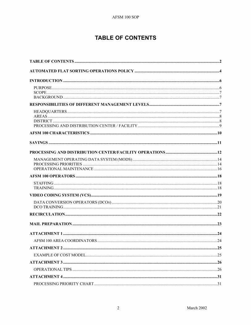
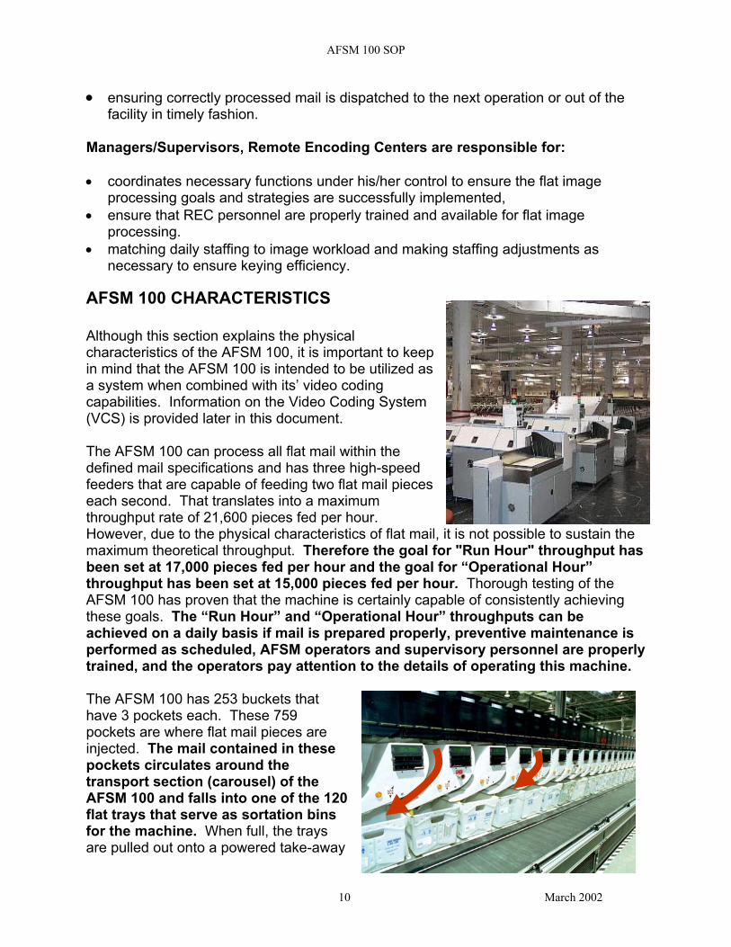
AFSM 100 CHARACTERISTICS Although this section explains the physical characteristics of the AFSM 100, it is important to kin mind that the AFSM 100 is intended to be utilizeda system when combined with its’ video coding capabilities. Information on the Video Coding System (VCS) is provided later in this document. The AFSM 100 can process all flat mail within the defined mail specifications and has three high-speed feeders that are capable of feeding two flat mail pieces each second. That translates into a maximum throughput rate of 21,600 pieces fed per hour. However, due to the physical characteristics of flat mail, it is not possible to sustain the maximum theoretical throughput. Therefore the goal for "Run Hour" throughput has been set at 17,000 pieces fed per hour and the goal for “Operational Hour” throughput has been set at 15,000 pieces fed per hour. Thorough testing of the AFSM 100 has proven that the machine is certainly capable of consistently achieving these goals. The “Run Hour” and “Operational Hour” throughputs can be achieved on a daily basis if mail is prepared properly, preventive maintenance is performed as scheduled, AFSM operators and supervisory personnel are properly trained, and the operators pay attention to the details of operating this machine. The AFSM 100 has 253 buckets that have 3 pockets each. These 759 pockets are where flat mail pieces are injected. The mail contained in these pockets circulates around the transport section (carousel) of the AFSM 100 and falls into one of the 120 flat trays that serve as sortation bins for the machine. When full, the trays are pulled out onto a powered take-away
10 March 2002

AFSM 100 SOP
conveyor. The take-away conveyor transports the trays to a powered buffer conveyor and extendable skate wheel system at the end of the machine where they can be placed into containers for dispatch. The take-away conveyor can also be connected to a Tray Management System (TMS). The AFSM 100 has Optical Character Recognition (OCR) and Bar Code Reader (BCR) capability that allows it to read an address or bar code to determine the proper sort location. The following are BCR/OCR read rates by mail type and should be considered average performance expectations. Note: These rates do not include the mail that is keyed and processed through the VCS.
First Class Flats-
OGP, MMP, SCF: 80-85% Incoming Secondary: 75%
Periodicals, Standard A
All Sort Plans: 93-97%
SAVINGS Budgeted savings for the AFSM 100 are typically expressed in annual work hours that must be saved for each machine deployed. The amount of work hours that must be saved per machine are determined on a site by site basis by Area In-Plant Support personnel. All sites may not be required to capture the same amount of savings per machine. Some sites will obviously be better able than others to capture more savings due to such things as mail mix and volume. However, all sites will be required to capture the maximum amount of savings available to them based on their own mail mix and volume. Another way to view savings for the AFSM 100 is to examine the costs associated with not utilizing the machine to its fullest capabilities. For every minute one of the individual feeders is not feeding mail at a run hour throughput rate of 17,000, the opportunity to process 94 pieces of mail is lost. The national average fully loaded cost per work hour in FY 2002 for a PS-5 manual clerk was $33.76 and for a PS-4 mail processor was $30.89. To process 94 pieces of mail at a manual productivity rate of 412 TPH would cost $7.70 calculated as follows
((94 / 412 TPH) * $33.76) To process 94 pieces of mail at an AFSM 100 productivity rate of 2600 TPH would cost $1.12 calculated as follows ((94 / 2,600 TPH) * $30.89)
11 March 2002
AFSM 100 SOP
Based on the difference in processing costs you can easily understand the importance of keeping the machine running at its fullest capacity. In order to effectively communicate the expected savings to field personnel a Microsoft Excel based model (example – Attachment 2) was developed. The model allows a site to determine the least costly processing mode by simulating processing by machine type. The simulations are based on local variables such as productivity, read rate, and cost per work hour. The model should be used with local and/or Area performance criteria to determine the savings that can be obtained based on which processing equipment is utilized. The "Cost Model" was distributed on a compact disc to each P&DC/F and In-Plant Support person who attended the Area AFSM 100 Orientations held during the spring of 2000. If your site does not have a copy of this model you should contact your Area AFSM 100 coordinator. Attachment 1 lists the Area Coordinators names, addresses, and phone numbers.
PROCESSING and DISTRIBUTION CENTER/FACILITY OPERATIONS With the deployment of the AFSM 100, additional machine capacity becomes available that must be optimized by properly managing mail flow. The AFSM100 processes mail approximately 2 - 3 times faster than the FMOCR/881 and each machine is intended to be utilized 20 hours per day. Given these parameters current patterns of processing should be reviewed to ensure the most efficient use of all flat sorting equipment. Operations managers need to continuously determine the availability of mail by type and class and process it on the equipment that will result in the lowest processing cost per piece. This must include consideration of REC processing issues as a factor of processing costs. A goal of 6,000,000 pieces of mail fed per AFSM 100 for Phase l sites per accounting period (AP) has been set by Headquarters Processing Operations. To illustrate the ease with which the AP goal can be achieved, the following calculation is provided – (15,000 pieces fed per hour throughput for 20 hours per day = 300,000 pieces fed per day) (300,000 pieces fed per day for 20 days = 6,000,000 pieces fed per AP) This example only assumes processing on 20 of the 28 days of an AP and a throughput of 15,000 pieces fed per hour, so you can see there is plenty of room for exceeding the Processing Operations goal. In addition, the Phase l AFSM 100s were justified with the intention of moving 300,000 pieces of manually processed flat mail up to the automation stream daily. This does not mean the 300,000 pieces of mail must be processed on the AFSM 100 exclusively. It does, however, mean that the mail should be removed from a manual operation and processed in an automated or mechanized operation. You must also
12 March 2002
AFSM 100 SOP
keep in mind that utilization of existing equipment should not suffer at the expense of moving mail to the AFSM 100, the volume of mechanized/automated flat mail should increase overall. This mail will come from Function 4 operations in the Stations/Branches and Associate Offices and Function 1 operations in the plant. The above goal allows more than enough time for maintenance personnel to perform the daily 3 hours of preventive maintenance tasks required to keep the AFSM 100 in optimal operating condition. The “slack time” that is allowed in the AP calculation also provides ample time for maintenance personnel to perform weekly and quarterly preventive maintenance on non-peak processing days. Maintenance personnel should work with processing operations and In-Plant Support personnel to determine the optimal time to perform scheduled maintenance. Under normal operating conditions the preventive maintenance should be scheduled to be performed within a 3 hour maintenance window. However, you must keep in mind this maintenance window will likely be extended for repairs that need to be made outside of the normal preventive maintenance requirement. A document titled “AFSM 100 Processing Priorities and Mail Flows” was created and distributed through Area AFSM coordinators to aid in understanding the changes that must be made to accommodate the movement of mail up the ladder. When used in conjunction with the “Cost Model” employees will have a better understanding of the reasons for making the changes required to implement a successful flats processing strategy. Additional operational tips are included as Attachment 3 to aid Processing and Distribution personnel in reaching the established goals and projected savings for the AFSM 100 program.
13 March 2002

AFSM 100 SOP
MANAGEMENT OPERATING DATA SYSTEM (MODS) The Management Operating Data System (MODS) numbers to be used for the AFSM 100, Video Coding System operations and associated Mail Preparation operations are as follows:
AFSM 100 PROCESSING LDC Composite 330C 12 Outgoing Primary 331 12 Outgoing Secondary 332 12 Managed Mail Program 333 12 Sectional Center Facility 334 12 Incoming City Primary 335 12 Incoming Secondary 336 12 Box Mail 337 12 Incoming Non-Scheme 338 12 Reserved 339 12 Video Coding System LDC Keying – Composite 380C 15 Keying (Plant) – Career Employee 381 15 Keying (Plant) – Transitional Employee 382 15 Keying (REC) – Dedicated to Flats 389 15 Keying (REC)–Shared VDTs(flats/letters) 388 15
PROCESSING PRIORITIES Mail processing supervisors should maximize the use of AFSM 100s in order to realize the savings associated with the machine and to improve service performance for our customers. Therefore, if there is insufficient volume to support the concurrent use of all types of equipment, the AFSM100 should be the processing mode of choice. Processing schedules by machine type should be developed well in advance of receiving an AFSM 100 to determine exactly when each piece of equipment will be run and what type of mail will be run on each. These plans should be based on a logical volume or flow based model such as the Flats Automation Requirements Model (FARM). The plan should also be based on eliminating manually processed flat volumes and a productivity improvement for all flat operations in general.
14 March 2002

AFSM 100 SOP
In addition to determining a plan of which mail type to run when, In-Plant Support personnel should design the sort plans used on the AFSM 100 to be efficient for the operators. This includes assigning high-density separations to the high numbered bins on each side of the machine (ie. bins 45 – 60 on the front and bins 110 – 119 on the back). This allows the operator on the side of the machine with bins 1 through 60 to spend most of his/her sweeping time closer to the buffer conveyor, thus making it more efficient for the operator to clear the full trays from the conveyor into mail transport equipment. By assigning the high-density bins to the high numbered bins on the backside of the machine, the operator will be closer to the feeders and therefore able to clear injector jams quicker if this is the injector jam clearing method preferred by the site. This reduces the time that a feeder is down due to an injector jam. This design also provides more time for an image to be keyed by a DCO before it reaches its destination bin, assuming the mail pieces that can’t be read by the BCR/OCR are of the same density as those that are readable. This is not the only way a sort plan could be designed. However, other layouts should take into account all aspects of efficiency when they are not designed as indicated here. Another time saving tip that aids in maximizing machine throughput is to have the operators feeding the AFSM 100 cooperate in clearing injector jams. When this method is used, the high-density bins should not be assigned to the high numbered bins on the backside of the machine. The high-density bins should be assigned to the lower numbered bins on the back side of the machine so the sweeper can assist in clearing trays from the buffer rollers. In order to explain this method an example of clearing an injector jam on feed station # 2 is used. EXAMPLE: When the injector jam occurs on feeder # 2, the operator on feeder # 1 is notified. The operator on feeder # 1 moves to the injector for feeder # 2 and clears the injector jam while the operator on feeder # 2 moves to feeder # 1 to keep it loaded with mail while the jam on feeder # 2 is being cleared by operator # 1. When the jam has been cleared the operator for feeder # 2 moves back to feeder # 2 and immediately starts the feeder. The operator for feeder # 1 returns to feeder # 1. This method will work for injector jams on any of the feeders without interrupting the loading, feeding, and running of the feeders that are still in operation. It maximizes machine throughput and allows better utilization of the operators time. A site should determine which of the two recommended injector jam clearing methods is most efficient for their site, or within their site by tour, and ensure consistent utilization of that method to avoid confusion as to which operator is responsible for clearing injector jams.
15 March 2002

AFSM 100 SOP
Due to the unique capability of the AFSM100 to allow keying and sorting of non-BCR/OCR readable mail (in near-real time), virtually all mail fed is successfully sorted. However, since the AFSM100 does not spray a bar code or ID tag on the mail, the BCR/OCR non-reads must be keyed at all levels of subsequent processing on the AFSM 100. It is important to remember that the mail piece (represented by an image) that requires processing by a Data Conversion Operator (DCO) is mixed in the same tray as those pieces read by the OCR or BCR. Therefore, if the mail flows to an operation other than an AFSM 100 operation it should be processed in an FMOCR operation. It is also important to note that if a determination is made to run the AFSM 100 in BCR/OCR only mode and not key non-readable mail, the supervisor must access the machine configuration screen to change the processing mode.
INJECTOR 2
FEEDER 1
FEEDER 2
FEEDER 3
The Processing Priority Chart (Attachment 4) should be used as the guide for determining the priority of where to process mail from different flat mail operations. This chart also provides the correct Content Identification Numbers (CINs) to be used with the implementation of the AFSM 100.
OPERATIONAL MAINTENANCE Based on the knowledge gained from implementing the letter mail automation program, operations personnel at all levels agree that an effective and on-going “Operational Maintenance” program is as important to the success of this program as well as regular scheduled maintenance. Operational maintenance as defined herein means: • •
the maintenance that occurs during the normal processing of mail the unscheduled observations that maintenance personnel make while observing a piece of equipment running mail
16 March 2002

AFSM 100 SOP
•
•
the time that a maintenance person takes to make minor adjustments or investigate a strange sound during a break or lunch period when the machine is not running and can be “tweaked” or the time spent cleaning the OCR camera lens in between runs.
There are other tasks that good maintenance personnel perform on a regular basis that are equally as important. The point is that just having a maintenance person stationed nearby instead of at the other end of the workroom floor or even on a different floor can save precious processing time when the machine is down or not operating to its fullest potential.
17 March 2002
AFSM 100 SOP
AFSM 100 OPERATORS
STAFFING Remote Encoding Centers (RECs) will perform flat image keying and adhere to the work rules, staffing mix, and work standards previously established for the RECs. Staffing for the AFSM 100 is:
● 3 operators for loading ● 2 operators for sweeping ● DCOs as needed, based on image generation rate
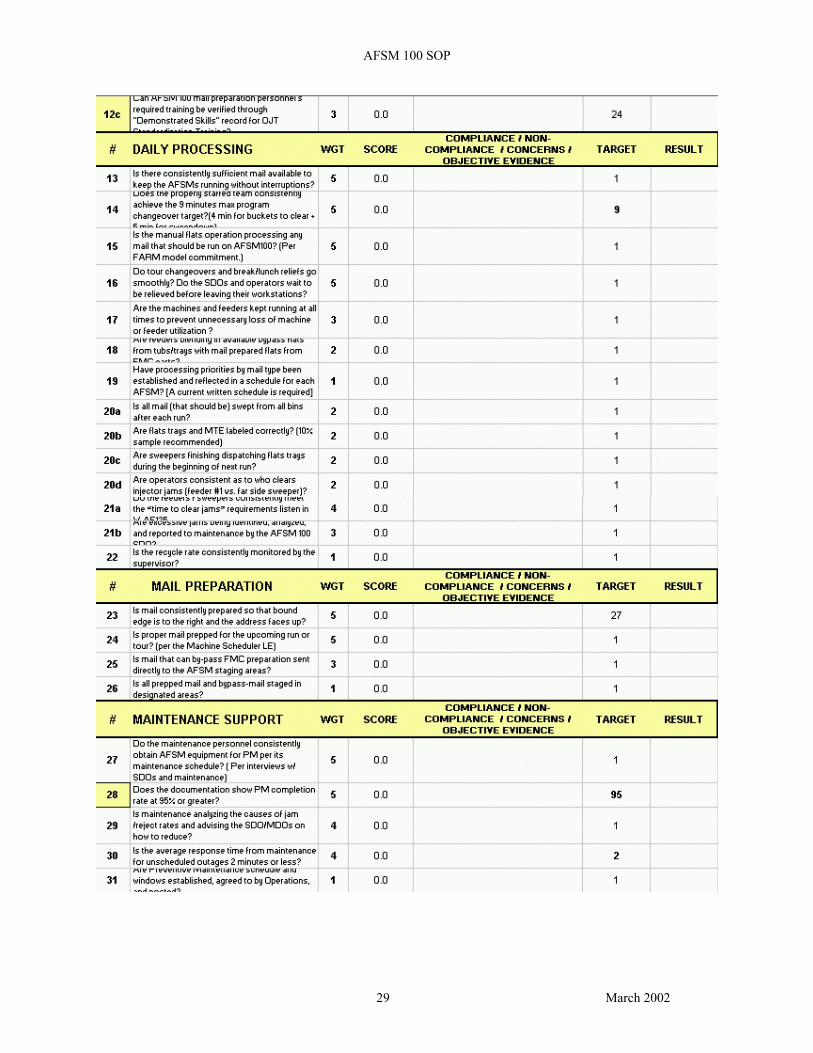
It is important to note that the sweeper operators on this machine are also responsible for removing the flat trays conveyed to the extendable buffer/conveyor at the end of the machine. In offices that do not have the AFSM 100 connected to a Tray Management System (TMS) the trays must be removed from the extendable buffer/conveyor and placed in mail transport equipment for either dispatch or relocation to another area on the workroom floor. If additional personnel are assigned this task, the savings attributed to the AFSM 100 will be decreased. If proper staffing is in place for operation of the AFSM 100 the “Utilization Goal” will provide savings in excess of those required to meet the budgeted workhour savings. When a run has been completed, it is recommended that all operators (feeders and sweepers) be assigned particular duties to sweep the machine, dispatch the trays, and change over to the next run or operation as quickly as possible. This change over function can be accomplished in as little as 3 to 5 minutes if performed properly. However, it has been observed that, when not properly performed or supervised, a change over can take much longer. See Attachment 5 for recommended Sweep Down procedures.
TRAINING Postal personnel that attend the contractor provided or related USPS provided Train-the-Trainer courses are responsible for ensuring operators and supervisors are sufficiently trained to accomplish the tasks assigned them. The major difference between this machine and other flat sorting machines is that the AFSM 100 is not an operator-paced machine. This difference is what makes poor technique highly visible and quickly evident when observed by someone who understands what the machine is capable of doing. In order to get the best throughput possible from the machine, operators must be properly trained on how to feed and sweep the AFSM 100.
18 March 2002
AFSM 100 SOP
Supervisors should be properly trained on how to monitor correct operation of the AFSM 100 system (including the VCS operation) through interpretation of system information and report data in addition to the physical operation aspects of the machine. A poorly or improperly trained supervisor will not realize the AFSM 100 operation is not being run efficiently. Personnel responsible for training supervisors and operators should observe the people they have trained for a reasonable amount of time after training is completed in order to determine if the training was effective and sufficient. As indicated in the savings section above, it is very important to keep the AFSM 100 fully utilized. Emphasis should be placed on the operator training provided by postal service Train-the-Trainers and include the viewing of videos developed by the contractor. The videos demonstrate the proper method for feeding and sweeping the machine. In addition, there are two other very informative videos that discuss and demonstrate the proper feeding and sweeping methods for the machine and mail preparation methods that were developed by Systems Process Integration, Engineering. If you do not have these videos you should contact your Area AFSM coordinator. A brief synopsis of the available training courses and materials is presented in Attachment 6 for your information.
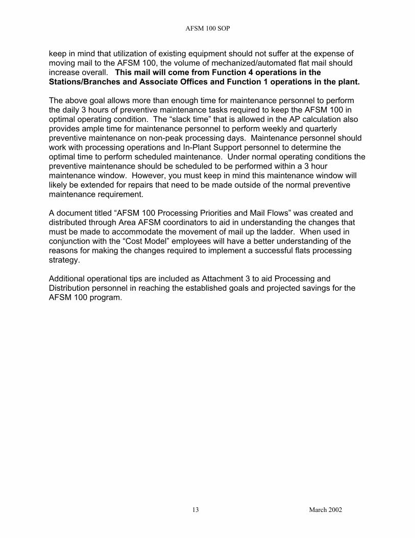
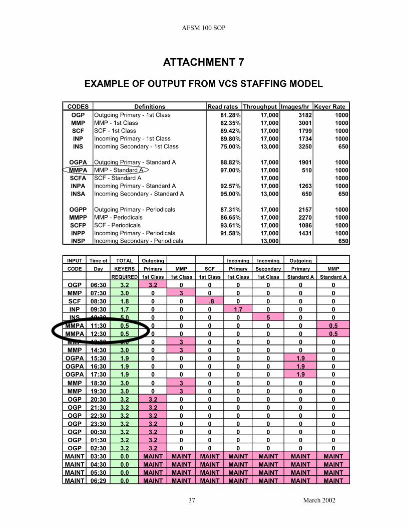
VIDEO CODING SYSTEM (VCS) The VCS provides the functionality required to key mail piece images that could not be finalized or sorted by the BCR/OCR on the AFSM 100. The VCS consists of a supervisor workstation and Video Display Terminals (VDTs) . Images are transmitted from the AFSM 100 to the VCS for processing by DCOs in near real time. THE IMAGES ARE NOT BUFFERED for processing at a later time, they remain in the system until they have been processed by a DCO or until a pre-set re-circulation rate has been reached. The re-circulation rate setting is very important and is discussed in more detail below. DCOs are assigned to key flat images at the REC. REC supervisors monitor the performance of the DCOs using the supervisor’s video control computer (VCC). A staffing model (Example - Attachment 7) was developed to aid in the determination of proper staffing in the VCS room. The model uses machine throughput, BCR/OCR accept rate, and a DCO keying rate to determine the average hourly staffing for the VCS function. The model is an Excel based spreadsheet and very easy to use. It has been distributed to the Area AFSM coordinators. If you do not have the model contact your coordinator. Careful consideration should be given to the staffing of the VCS operation. It is not productive or cost efficient to attempt to staff the VCS operation in a continuous fashion
19 March 2002
AFSM 100 SOP
with a constant number of DCOs since BCR/OCR read rates can vary widely. In fact, when image volume projections indicate a need for one or less keyers (DCOs) as is indicated for the “MMPA Input Code” circled on Attachment 7 it is possible that it is not efficient to staff the VCS operation at all. A review of what the cost would be to process a small volume of non-readable mail in another operation should be performed to determine whether or not to staff the VCS operation. Another approach to processing this small volume of mail would be to stage it for processing on the AFSM/VCS at a time during the operation when the requirement for DCOs would be greater than one. The following should be considered normal operating parameters for the VCS:
● finalization rate of 95% for all Images,
● VCS Productivity of 1000 Images per console hour for all mail types except Incoming Secondary,
● 3 to 5 Keystrokes Per Image (KPI) for all mail types except Incoming
Secondary,
● VCS Productivity of 750 Images per console hour for Incoming Secondary,
● 8 to 10 Keystrokes Per Image (KPI) for Incoming Secondary.
DATA CONVERSION OPERATORS (DCOs) Plant Remote Encoding Centers (RECs) are part of the national REC network. Under the Memorandum of Understanding with the American Postal Workers Union dated November 3rd 1993, the network mandates use of a ratio of 30 percent career work hours to 70 percent Transitional Employee (TE) work hours. This ratio is based on a national annual percentage of workhours in ALL RECs supporting both letter RBCS operations and the AFSM 100 operation nationwide. Area office personnel are responsible for making allocations, monitoring and maintaining the 30 / 70 ratio in total for all REC sites within their area of responsibility. The Area ratio does not have to be maintained on a site by site basis. Failure to maintain a minimum of 30% career work hours nationally has the potential for incurring significant penalties. Data Conversion Operators who successfully pass the keyer training are expected to maintain minimum standards. Those standards have been set at 7,150 keystrokes per hour with a 98% accuracy rate. Keyer Performance Evaluation Review (KPER) software is used to monitor DCO performance. REC Supervisors must run a minimum of one 25 piece keying sample per week per DCO to ensure quality distribution. Note: For more information on KPER, read the Keyer Performance Evaluation Review
20 March 2002
AFSM 100 SOP
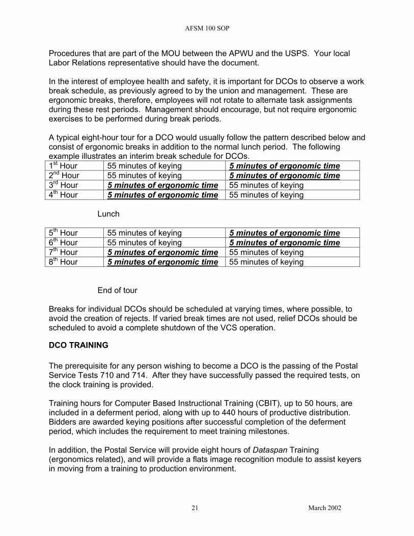
Procedures that are part of the MOU between the APWU and the USPS. Your local Labor Relations representative should have the document. In the interest of employee health and safety, it is important for DCOs to observe a work break schedule, as previously agreed to by the union and management. These are ergonomic breaks, therefore, employees will not rotate to alternate task assignments during these rest periods. Management should encourage, but not require ergonomic exercises to be performed during break periods. A typical eight-hour tour for a DCO would usually follow the pattern described below and consist of ergonomic breaks in addition to the normal lunch period. The following example illustrates an interim break schedule for DCOs. 1st Hour 55 minutes of keying 5 minutes of ergonomic time 2nd Hour 55 minutes of keying 5 minutes of ergonomic time 3rd Hour 5 minutes of ergonomic time 55 minutes of keying 4th Hour 5 minutes of ergonomic time 55 minutes of keying
Lunch
5th Hour 55 minutes of keying 5 minutes of ergonomic time 6th Hour 55 minutes of keying 5 minutes of ergonomic time 7th Hour 5 minutes of ergonomic time 55 minutes of keying 8th Hour 5 minutes of ergonomic time 55 minutes of keying End of tour Breaks for individual DCOs should be scheduled at varying times, where possible, to avoid the creation of rejects. If varied break times are not used, relief DCOs should be scheduled to avoid a complete shutdown of the VCS operation.
DCO TRAINING The prerequisite for any person wishing to become a DCO is the passing of the Postal Service Tests 710 and 714. After they have successfully passed the required tests, on the clock training is provided. Training hours for Computer Based Instructional Training (CBIT), up to 50 hours, are included in a deferment period, along with up to 440 hours of productive distribution. Bidders are awarded keying positions after successful completion of the deferment period, which includes the requirement to meet training milestones. In addition, the Postal Service will provide eight hours of Dataspan Training (ergonomics related), and will provide a flats image recognition module to assist keyers in moving from a training to production environment.
21 March 2002

AFSM 100 SOP
Keyer trainees also receive 8 hours of ergonomics training and 2 hours of flats familiarization training in addition to CBIT (60 hours total). Attachment 6 provides the course numbers and additional information on the training courses available for DCOs.
RECIRCULATION The mail pieces represented by images sent to the VCS continue to circulate in the machine carousel until they are resolved or a pre-set re-circulation rate has been met. This re-circulation rate is very important to the successful operation of the machine and can adversely affect throughput of the machine if set too high. The operational settings recommended are Zero (0) for the “VCS Waiting for Results” (which allows 110 seconds to key an image if the Reject bin is bin 120), and One (1) for the “Machine Re-circulation Value”. The combination of these settings means that a mail piece awaiting VCS image resolution will remain in its bucket on the carousel and begin re-circulating if the image resolution is not available when the mail piece is approximately 5 bins prior to its intended destination bin on its’ first pass around the machine. If no sortation result is available from the VCS operation prior to reaching bin 120, the mail piece becomes a “Timeout”. Mail pieces that become “Timeouts” will fall in the bin/tray assigned for timeouts. This mail must then be re-handled on the AFSM. The machine recirculation setting of 1 allows mail that has a valid BCR/OCR or VCS result on its first pass around the carousel to re-circulate if it cannot be dropped because the destination tray is full or not present. If the destination bin is still not available on the second pass, the mail piece will drop in the bin designated as “Recycle Rejects” which is normally the mechanical reject bin. If a reject bin is full, a piece of mail destined for the reject bin will continue to recirculate in the machine taking up space that could otherwise be used for successful sortation of mail. It is very important to sweep full bins in a timely fashion to avoid the unnecessary re-circulation of mail.
22 March 2002

AFSM 100 SOP
It is possible for the supervisor to set the recirculation setting up to 5 re-circulations. However, if recirculation is set higher than 1, and the DCOs can not keep up with the demand for keying, throughput on the AFSM is adversely impacted. A direct correlation can be drawn between the buckets occupied by re-circulating mail and a reduction in AFSM 100 throughput. Caution should also be exercised to ensure the AFSM100 is not overloaded with non-BCR/OCR readable mail. This will cause excessive recirculation if the non-readable mail being fed exceeds the keying rate of the DCOs or available DCO staffing.
MAIL PREPARATION Preparing mail to be fed on the AFSM 100 in an efficient and timely manner is a very important step in achieving the established throughput goals. The fact that the AFSM 100, with automatic feeders, processes mail 2 to 3 times faster than the FSM 881 makes this issue very visible (See Flat Mail Cart SOP for further details on Mail Prep)
23 March 2002

AFSM 100 SOP
ATTACHMENT 1
AFSM 100 AREA COORDINATORS
Name Area Office Phone Number Robert Prince Eastern Area 412-494-2549 Fernando Pereira Capital Metro Area 301-548-1416 Jug Bedi Capital Metro Area 301-548-1407 Patricia Davis Great Lakes Area 630-539-4752 Jim Martin New York Metro Area 718-321-5754 Dave Englander New York Metro Area 718-321-5871 Ron Grady Northeast Area 860-285-7213
Brad Fulton Pacific Area 650-635-3042 Bill Fisher Southeast Area 901-747-7339 Larry Kintner Southeast Area 901-747-7637 Melisa McCrea Southwest Area 214-819-8618 Ken Brown Southwest Area 214-819-8623 Gary Hegstad Western Area 303-313-5973
24 March 2002

AFSM 100 SOP
ATTACHMENT 2
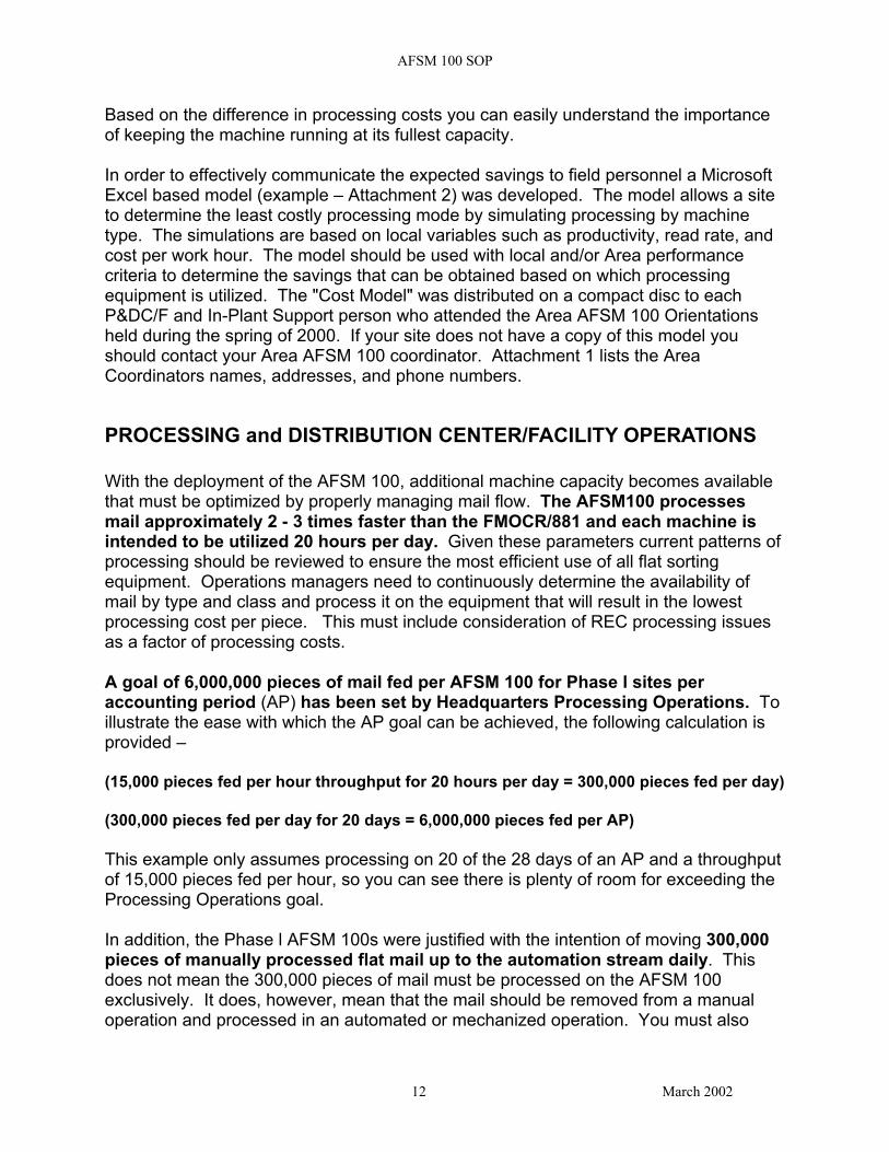
EXAMPLE OF COST MODEL
1
234567
89
101112131415161718192021222324252627282930313233343536373839404142
A B C D E F G H I
Flats Processing Crew Crew Crew Crew Crew Crew
Cost Comparisons Size Size Size Size Size Size1 5 3.2 6 6 6
Total Manual AFSM O AFSM K FSM 881 FSMOCR FSM 1000Volume Productivity Productivity Productivity Productivity Productivity Productivity
1,000 419 2,066 1,000 555 626 554Cost/hour $31.27 $26.28 $26.28 $31.27 $26.28 $31.27
Runtime 0.06 Runtime 0.27 Runtime 0.30Accept Accepted Keyed Accept Accepted Rejected Accept Keyed Rejected
Rate Volume Volume Rate Volume Volume Rate Volume Volume81.00% 810 190 81.18% 812 188 95.00% 950 50
Residual Residual Number ofReject Reject Keyers Woodwork Rate Volume Required Rate3% 30 6.0 2%
AFSM100 AFSM100 Total FSMOCR FSM881Cost to Cost to Cost of Cost to Cost to Process Process Accepted Process Process
Accepted Keyed and Accepted KeyedVolume Volume Keyed Volume Volume
$10.31 $4.99 $15.30 $34.08 $53.53
Cost to Cost to Cost to Process Process Process Cost to Cost to Cost to Cost to Cost to Residual Residual Residual Process Process Process Process Process
Reject Reject Reject Reject Reject Reject Reject RejectVolume Volume Volume Volume Volume Volume Volume Volume
on on on on onFSM881 FSM1000 Manually FSM881 FSM1000 Manually FSM1000 Manually
$1.61 $1.61 $2.24 $10.07 $10.09 $14.05 $2.68 $3.73
Manual Manual Manual Manual ManualCost Cost Cost Cost Costfrom from from from from
FSM881 FSM1000 FSM881 FSM1000 FSM1000Rejects Rejects Rejects Rejects Rejects
$0.11 $0.11 $0.72 $0.72 $0.19
Total Cost $17.02 $17.02 $17.54 $44.87 $44.89 $48.13 $56.40 $57.26
FSM881AFSM100 FSMOCR
J
Note: The above picture does not show the entire cost comparison spreadsheet. Due to size limitations it only shows a comparison of three machine types.
25 March 2002

AFSM 100 SOP
ATTACHMENT 3
OPERATIONAL TIPS Listed below are a few useful tips that operations personnel visiting production sites have observed to be useful.
Manage and monitor the VCS operation at the REC. Performance monitoring of the entire VCS, individual DCOs, and editing tasks can all be performed at the VCC. I It is critical that the Plant and REC establish an ongoing communications channel concerning plant and REC operations in order to maximize total system efficiency. Any disruptions to any part of the total operation must be communicated immediately. Events such as unscheduled downtime, breaks, image quality issues, system problems or other unforeseen occurrences must be reported right away. Refer to the SPS Sort Plan documentation included on the AFSM 100 CD provided at Area AFSM 100 Orientations for many tips and suggestions for setting up special bins and high-density bins on the machine. It is more efficient to combine low volume zones into one super sort plan than to create separate sort plans for a group of zones to be run simultaneously. By using the super sort plan method, runtime will be increased and down time will be minimized. Have the operator for feeder 1 clear all jams at injectors 1, 2,and 3. The operator whose feeder has the jam can move down and fill in for operator 1 at feeder 1. The benefit of this approach to clearing injector jams is that the sweeper on the backside of the AFSM 100 can concentrate on sweeping duties and clearing full trays from the backside of the machine. It also minimizes downtime of the feeders and the machine by minimizing the response time to clear an injector jam. The operator at console 1 must be alert to injector jams for feeders 2 and 3 in addition to injector jams on feeder 1. Proper training and an alert operator will make this method a success. If you choose to use the method for clearing injector jams described above, your sort programs should have the high-density bins placed at the end of the machine farthest from the feeders. This puts the sweepers at the same end of the machine as the buffer/conveyor where the trays accumulate prior to being swept into containers. The bin assigned for Mechanical Rejects may also contain other reject categories. The sort plan developer has the option to isolate any of the reject categories for diagnostic purposes or to create a more efficient operation.
26 March 2002

AFSM 100 SOP
However, before doing so, the developer should examine the reasons for isolating the rejects into separate bins. They should make sure the additional breakouts are justified since doing so reduces the number of sortation bins available for distribution. The various reject categories are described in the SPS documentation for the AFSM 100. Below is a checklist that can be used as an aid in reviewing AFSM 100 operations.
27 March 2002

AFSM 100 SOP
AFSM 100 STANDARDIZATION CHECKLIST
28 March 2002
AFSM 100 SOP
29 March 2002

AFSM 100 SOP
30 March 2002

AFSM 100 SOP
ATTACHMENT 4
PROCESSING PRIORITY CHART Includes CIN Numbers
Destinating Facility Originating Office Flat
Tub CIN Code AFSM 100
MPC: 1
FSM 881 Key
MPC: 2
FSM 881 BC
MPC: 1
FSM 881 OCR MPC:
2
FSM 1000 KEY MPC:
2, 4
FSM 1000 BC
MPC: 1
Manual MPC: 4
AFSM 100 FCM FLATS VCODE CIN # 233-238 MPC: 1
1 4 3 3 5
FSM 881 FCM FLATS NON-BC CIN #s 278-284 MPC: 2
1 2 3
FSM 881 FCM FLTS BC CIN #s 272-277 MPC:1
1 2 3 4
FCM FLTS OCR-NR CIN #s 223-228 MPC: 2, 4
2 1* 3
FSM 1000 FCM FLTS NON-BC CIN #s 278-284 MPC: 4
1 2
FSM 1000 FCM FLTS BC CIN #s 272-277 MPC:1
1 2
*Recommend using an 881 keying sort program for FMOCR non-reads from upstream operations or facility
31 March 2002

AFSM 100 SOP
ATTACHMENT 5
AFSM 100 MACHINE SWEEP DOWN PROCEDURES. Changeover from one sort plan to another should be accomplished in 3-5 minutes from the time all mail is emptied from the transport pockets, until the AFSM 100 begins the next run. The individual duties are as follows: Supervisor: During the current run: Determine if the feeders and sweepers will rotate positions after the changeover or remain where they are. Advise all employees of your decision. Print labels for the next sortplan to be run. Have the sweepers place the labels in the label holders on the machine during the current run, if possible, so they will be available to be placed in the trays. Ensure there are enough empty flat trays at each sweepside of the machine. Ensure there is sufficient MTE available at the dispatch end of the machine. Ensure mail for the next run is staged in the immediate area of the machine. At the end of the current run: When the AFSM 100 supervisors screen shows that all the buckets are empty, advise all employees and initiate the generation and printing of the End of Run (EOR) report. Monitor all employees to ensure the changeover is done quickly, accurately, and efficiently.
Feeder # 1 Before end of current run: Complete loading all mail on Feeder #1 for the current run. Remove empty equipment and position the Flat Mail Cart (FMC) with mail for the next run in front of Feeder #1.
32 March 2002
AFSM 100 SOP
Carefully release straps from the FMC and load mail for the next run onto the feed table behind the support blade as the current run finishes. In this way the feed table will be loaded for the next run. At the end of the current run: After the last piece of mail is fed, go to the far end of the machine (on the Bin 61 – 120 side) and begin distributing full trays from the conveyor belt into the appropriate container. After the sweeper on the bin 61 – 120 side has put the last empty tray in place, go back to Feeder #1 and start the machine for the next run as soon as the entire sweep is complete. Feeder # 2 Prior to the end of the current run: Complete loading of all mail on Feeder #2 for the current run. Remove empty equipment and position FMC with mail for the next run in front of Feeder #2. Release straps from the FMC and load mail for the next run onto the feed table behind the support blade as the current run finishes. In this way the feed table will be loaded for the next run. At the end of the current run: After last piece is fed go to far end of machine (on the Bin 1 – 60 side) and begin distributing full trays from the conveyor belt into the appropriate container. After sweeper on the bin 1 – 60 side has put the last empty tray in place, go back to Feeder # 2 and start your feeder as soon as the entire sweep is completed. Feeder # 3 Prior to the end of the current run: Complete loading of all mail on Feeder #3 for the current run. Remove empty equipment and position FMC with mail for the next run in front of Feeder #3.
33 March 2002

AFSM 100 SOP
Release straps from the FMC and load mail for the next run onto the feed table behind the support blade as the current run finishes. In this way the feed table will be loaded for the next run. At the end of the current run: Remain at the feeder end and make sure all 3 feeders are loaded with mail and ready to run (i.e. move support blades behind the mail on the consoles) as soon as the entire sweep is complete. Sweeper, Near Side, Bins 1-60 Before the end of the current run: If labels are not already in the label holder slots for the next run, place labels for the next run in the proper slot of the label holders located above each bin. Replace tubs at all flashing light locations and clear full trays from the end of the machine. After the end of the current run: When the supervisor advises that the buckets are empty, start at bin # 60, and pull all the flat trays, two at a time, working your way back to bin # 1. After you pull bin # 1, begin inserting empty trays in the machine, starting with bin # 1 and working down to bin # 60.
Note – An alternate method is to pull out two full trays and immediately replace them with two empty trays. The supervisor should determine which method is most efficient for the current operators and ensure it is followed.
After last empty is in place, go to end of conveyor and finish removing full trays and distribute into the appropriate container. After all trays have been removed from the conveyor, return to bin # 60, and begin labeling the flat trays for the new run. Work your way back to bin # 1 keeping alert for any flashing lights due to bins filling during the new run. Set up empty MTE at the end of the machine for dispatch of the mail for the new run.
34 March 2002
AFSM 100 SOP
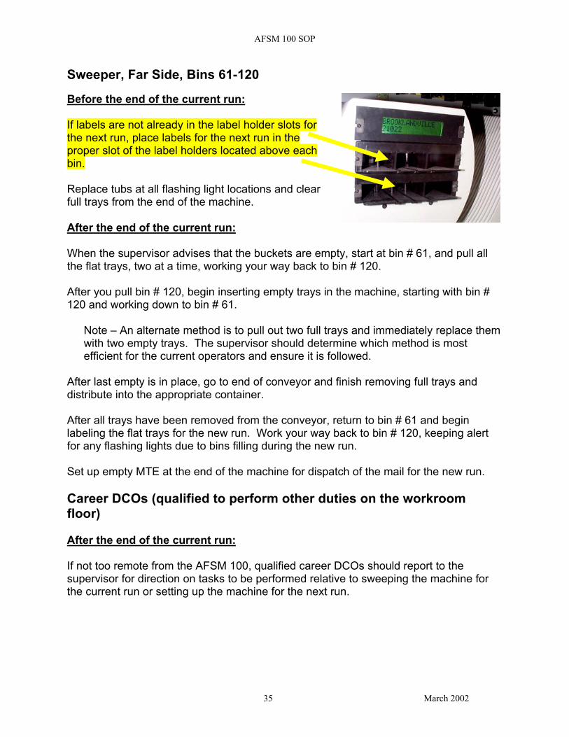
Sweeper, Far Side, Bins 61-120 Before the end of the current run: If labels are not already in the label holder slots for the next run, place labels for the next run in the proper slot of the label holders located above each bin. Replace tubs at all flashing light locations and clear full trays from the end of the machine. After the end of the current run: When the supervisor advises that the buckets are empty, start at bin # 61, and pull all the flat trays, two at a time, working your way back to bin # 120. After you pull bin # 120, begin inserting empty trays in the machine, starting with bin # 120 and working down to bin # 61.
Note – An alternate method is to pull out two full trays and immediately replace them with two empty trays. The supervisor should determine which method is most efficient for the current operators and ensure it is followed.
After last empty is in place, go to end of conveyor and finish removing full trays and distribute into the appropriate container. After all trays have been removed from the conveyor, return to bin # 61 and begin labeling the flat trays for the new run. Work your way back to bin # 120, keeping alert for any flashing lights due to bins filling during the new run. Set up empty MTE at the end of the machine for dispatch of the mail for the new run. Career DCOs (qualified to perform other duties on the workroom floor) After the end of the current run: If not too remote from the AFSM 100, qualified career DCOs should report to the supervisor for direction on tasks to be performed relative to sweeping the machine for the current run or setting up the machine for the next run.
35 March 2002

AFSM 100 SOP
ATTACHMENT 6
TRAINING COURSES Course 50580-00 Supervisor/Operator Train The Trainer (TTT) 40 hours Each site sends 2 people and after this training they will be able to train the supervisors and operators at their site. Materials: VCS User Guide, VCS Supervisor Student Training Manual, VCS Supervisor Facilitator Guide, Supervisor/Operator Facilitator Guide, Operator/Clerk Student Training Manual, Supervisor Student training Manual, User Guide, and video(Feeder Station Operator Training) Course 50581-00 Keyer TTT 56 hours (40 CBIT/16 Ergonomics) Each site sends 2 people and after this training they are able to train the DCOs(and supervisors) at their site. Materials:Keyer Trainee Handbook, Keyer Handbook, Dataspan Facilitator Guide, Dataspan Student book, Dataspan videos, Dataspan overheads(paper copy) and the engineering video that gives the overview of the AFSM-100(used at the Roadshows) Course 50582-00 Supervisor Training 16 hours Local training. Materials:VCS Supervisor Student Training Manual,Supervisor Student training Manual, User Guide, VCS User Guide and seeing the both videos Course 50583-00 Operator Training 2 hours Local training. Materials: Operator/Clerk Student Training Manual and seeing both videos. Course 50584-00 DCO Training 58 hours (50 CBIT/2 Flats transition) Local training done in VCS room using VDT. Course 19201-00 Dataspan Training 8 hours Increases the health, comfort and productivity of many types of data entry employees by teaching methods of fatigue relief and heightening awareness of ergonomics. Course 55601-15 AFSM 100 w/OCR/VCS System Maintenance 4 weeks Target audience is Electronic Technicians. Training is located at contractor’s facility. All seats assigned based on deployment schedule. Course 55601-31 AFSM 100 Maintenance 3 weeks Target audience is Maintenance Mechanic, Mail Processing Equipment. Training is located at contractor’s facility. All seats assigned based on deployment schedule.
36 March 2002
AFSM 100 SOP
37 March 2002
ATTACHMENT 7
EXAMPLE OF OUTPUT FROM VCS STAFFING MODEL
CODES Definitions Read rates Throughput Images/hr Keyer RateOGP Outgoing Primary - 1st Class 81.28% 17,000 3182 1000MMP MMP - 1st Class 82.35% 17,000 3001 1000SCF SCF - 1st Class 89.42% 17,000 1799 1000INP Incoming Primary - 1st Class 89.80% 17,000 1734 1000INS Incoming Secondary - 1st Class 75.00% 13,000 3250 650
OGPA Outgoing Primary - Standard A 88.82% 17,000 1901 1000MMPA MMP - Standard A 97.00% 17,000 510 1000SCFA SCF - Standard A 17,000 1000INPA Incoming Primary - Standard A 92.57% 17,000 1263 1000INSA Incoming Secondary - Standard A 95.00% 13,000 650 650
OGPP Outgoing Primary - Periodicals 87.31% 17,000 2157 1000MMPP MMP - Periodicals 86.65% 17,000 2270 1000SCFP SCF - Periodicals 93.61% 17,000 1086 1000INPP Incoming Primary - Periodicals 91.58% 17,000 1431 1000INSP Incoming Secondary - Periodicals 13,000 650
S 1
INPUT Time of TOTAL Outgoing Incoming Incoming OutgoingCODE Day KEYERS Primary MMP CF Primary Secondary Primary MMP
REQUIRED 1st Class 1st Class 1st Class 1st Class 1st Class Standard A Standard AOGP 06:30 3.2 3.2 0 0 0 0 0 0MMP 07:30 3.0 0 3 0 0 0 0 0SCF 08:30 1.8 0 0 .8 0 0 0 0INP 09:30 1.7 0 0 0 1.7 0 0 0INS 10:30 5.0 0 0 0 0 5 0 0
MMPA 11:30 0.5 0 0 0 0 0 0 0.5MMPA 12:30 0.5 0 0 0 0 0 0 0.5MMP 13:30 3.0 0 3 0 0 0 0 0MMP 14:30 3.0 0 3 0 0 0 0 0
OGPA 15:30 1.9 0 0 0 0 0 1.9 0OGPA 16:30 1.9 0 0 0 0 0 1.9 0OGPA 17:30 1.9 0 0 0 0 0 1.9 0MMP 18:30 3.0 0 3 0 0 0 0 0MMP 19:30 3.0 0 3 0 0 0 0 0OGP 20:30 3.2 3.2 0 0 0 0 0 0OGP 21:30 3.2 3.2 0 0 0 0 0 0OGP 22:30 3.2 3.2 0 0 0 0 0 0OGP 23:30 3.2 3.2 0 0 0 0 0 0OGP 00:30 3.2 3.2 0 0 0 0 0 0OGP 01:30 3.2 3.2 0 0 0 0 0 0OGP 02:30 3.2 3.2 0 0 0 0 0 0
MAINT 03:30 0.0 MAINT MAINT MAINT MAINT MAINT MAINT MAINTMAINT 04:30 0.0 MAINT MAINT MAINT MAINT MAINT MAINT MAINTMAINT 05:30 0.0 MAINT MAINT MAINT MAINT MAINT MAINT MAINTMAINT 06:29 0.0 MAINT MAINT MAINT MAINT MAINT MAINT MAINT