Embed Size (px)
Citation preview

AFRL-RW-EG-TP-2010-098
The Advanced Guided Weapon Testbed (AGWT) at the Air Force Research Laboratory Munitions Directorate
Craig Ewing Air Force Research Laboratory, Munitions Directorate AFRL/RWGG Eglin AFB, FL 32542-6810 August 2010 This work has been submitted to the American Institute of Aeronautics and Astronautics (AIAA) for presentation at, and publication in proceedings of, the Modeling and Simulation Technologies Conference in Chicago, IL, 10-13 Aug 09. The author is a U.S. Government employee working within the scope of his position; therefore, the U.S. Government is owner of the work. If published, American Institute of Aeronautics and Astronautics may assert copyright. If so, the Government has the right to copy, distribute, and use the work. Any other form of use is subject to copyright restrictions.
DISTRIBUTION A. Approved for public release, distribution unlimited. 96th ABW/PA Approval and Clearance # 96ABW-2009-0284, dated August 2009.
AIR FORCE RESEARCH LABORATORY MUNITIONS DIRECTORATE
Eglin Air Force Base, FL 32542United States Air Force Air Force Materiel Command

5(3257�'2&80(17$7,21�3$*( )RUP�$SSURYHG
20%�1R�����������
����5(3257�'$7(��''�00�<<<<� ����5(3257�7<3(�
����7,7/(�$1'�68%7,7/(
�D���&2175$&7�180%(5
����$87+25�6�
����3(5)250,1*�25*$1,=$7,21�1$0(�6��$1'�$''5(66�(6�
����6321625,1*�021,725,1*�$*(1&<�1$0(�6��$1'�$''5(66�(6�
���3(5)250,1*�25*$1,=$7,21
����5(3257�180%(5
����6321625�021,7256�$&521<0�6�
����6833/(0(17$5<�127(6
����',675,%87,21�$9$,/$%,/,7<�67$7(0(17
����$%675$&7
����68%-(&7�7(506
����180%(5
������2)�
������3$*(6
��D��1$0(�2)�5(63216,%/(�3(5621�
��D���5(3257
E��$%675$&7 F��7+,6�3$*(
����/,0,7$7,21�2)
������$%675$&7
6WDQGDUG�)RUP������5HY�������
3UHVFULEHG�E\�$16,�6WG��=�����
7KH�SXEOLF�UHSRUWLQJ�EXUGHQ�IRU�WKLV�FROOHFWLRQ�RI� LQIRUPDWLRQ�LV�HVWLPDWHG�WR�DYHUDJH���KRXU�SHU�UHVSRQVH�� LQFOXGLQJ�WKH�WLPH�IRU�UHYLHZLQJ�LQVWUXFWLRQV��VHDUFKLQJ�H[LVWLQJ�GDWD�VRXUFHV�
JDWKHULQJ�DQG�PDLQWDLQLQJ�WKH�GDWD�QHHGHG��DQG�FRPSOHWLQJ�DQG�UHYLHZLQJ�WKH�FROOHFWLRQ�RI�LQIRUPDWLRQ���6HQG�FRPPHQWV�UHJDUGLQJ�WKLV�EXUGHQ�HVWLPDWH�RU�DQ\�RWKHU�DVSHFW�RI�WKLV�FROOHFWLRQ
RI� LQIRUPDWLRQ�� LQFOXGLQJ� VXJJHVWLRQV� IRU� UHGXFLQJ� WKH� EXUGHQ�� WR� 'HSDUWPHQW� RI� 'HIHQVH�� :DVKLQJWRQ� +HDGTXDUWHUV� 6HUYLFHV�� 'LUHFWRUDWH� IRU� ,QIRUPDWLRQ� 2SHUDWLRQV� DQG� 5HSRUWV
������������������-HIIHUVRQ�'DYLV�+LJKZD\��6XLWH�������$UOLQJWRQ��9$���������������5HVSRQGHQWV�VKRXOG�EH�DZDUH�WKDW�QRWZLWKVWDQGLQJ�DQ\�RWKHU�SURYLVLRQ�RI�ODZ��QR�SHUVRQ�VKDOO�EH
VXEMHFW�WR�DQ\�SHQDOW\�IRU�IDLOLQJ�WR�FRPSO\�ZLWK�D�FROOHFWLRQ�RI�LQIRUPDWLRQ�LI�LW�GRHV�QRW�GLVSOD\�D�FXUUHQWO\�YDOLG�20%�FRQWURO�QXPEHU�
3/($6(�'2�127�5(7851�<285��)250�72�7+(�$%29(�$''5(66���
����'$7(6�&29(5('��)URP���7R�
�E���*5$17�180%(5
�F���352*5$0�(/(0(17�180%(5
�G���352-(&7�180%(5
�H���7$6.�180%(5
�I���:25.�81,7�180%(5
����6321625�021,7256�5(3257�
������180%(5�6�
����6(&85,7<�&/$66,),&$7,21�2)�
��E��7(/(3+21(�180%(5��,QFOXGH�DUHD�FRGH�
18-08-2010 Conference Paper Aug 08 - Aug 09
The Advanced Guided Weapon Testbed (AGWT) at the Air Force Research Laboratory Munitions Directorate
NA
NA
2068
85
00
Craig M. Ewing
Air Force Research Laboratory Munitions Directorate AFRL/RWGG Eglin AFB, FL 32542-6810
AFRL-RW-EG-TP-200****
Air Force Research Laboratory Munitions Directorate AFRL/RWGG Eglin AFB, FL 32542-6810
AFRL-RW-EG
SAME AS BLOCK 8
DISTRIBUTION A: Approved for public release; distribution unlimited. Approval Confirmation 96 ABW/PA # 96ABW-2009-0284; dated August 2009.
This paper describes the capabilities of the Kinetic Kill Vehicle Hardware-in-the-Loop Simulator (KHILS) facility and the Virtual Munition Simulator (VMS) facility co-located at the AFRL Munitions Directorate, Eglin Air Force Base, Florida. Together they make up the Advanced Guided Weapon Testbed (AGWT) used to research advanced guidance components using hardware-in-the-loop simulation as well as the exploitation and investigation of new weapon concepts through the use of distributed simulation and wargaming.
Hardware-In-The Loop (HWIL), Munition Simulation, Weapon Testbed, Advance Guidance
UNCLASSIFIED UNCLASSIFIED UNCLASSIFIED UL13
Shawn M. Goodrich
850-882-4628
American Institute of Aeronautics and Astronautics
1
The Advanced Guided Weapon Testbed (AGWT) at the
Air Force Research Laboratory Munitions Directorate
Craig M. Ewing1
AFRL/RWGG, Eglin AFB, FL 32542
This paper describes the capabilities of the Kinetic Kill Vehicle Hardware-in-the-Loop
Simulator (KHILS) facility and the Virtual Munition Simulator (VMS) facility co-located at
the AFRL Munitions Directorate, Eglin Air Force Base, Florida. Together they make up the
Advanced Guided Weapon Testbed (AGWT) used to research advanced guidance
components using hardware-in-the-loop simulation as well as the exploitation and
investigation of new weapon concepts through the use of distributed simulation and
wargaming.
I. Introduction
The Air Force Research Laboratory Munitions Directorate’s (AFRL/RW) mission is to develop, integrate, and
transition science and technologies for air-launched munitions for the defeat of ground, air, space, and cyber targets.
These technologies advance warfighter capabilities through the development of guided munitions that operate
autonomously or semi-autonomously to acquire, track, engage, and kill moving and fixed targets. Many of these
new weapon systems are becoming highly communicative and rely on multi-sensor data fusion, human-in-the-loop
confirmation, and increased fire control for cooperative attack.
AFRL/RW shares the DoD and AF vision that synthetic, or virtual, testing of these increasingly complex weapon
systems will play a critical role in future success on the joint battlefield. To determine which guided weapon
concepts and technologies are the most beneficial to the warfighter they need to have a good understanding of the
kind of capabilities that advanced technology can bring to the joint and coalition battlefield. The AGWT allows for
improved system effectiveness on the battlefield by getting advanced weapons’ concepts into the hands of the
warfighter early in the weapons life cycle, providing an optimized solution, maximizing interoperability, and
reducing risk and cost by utilizing a high fidelity simulation to augment flight tests.
Made possible by the investment and direction of the Missile Defense Agency (MDA) since 1987, and with the
addition of Air Force funding in more recent years; the KHILS facility mission focuses on high fidelity hardware-in-
the-loop (HWIL) simulation of guided hit to kill weapons.1 KHILS serves as a testbed for development of
hardware-in-the-loop test technologies for agencies around the country, such as scene projectors, projector control
electronics, high frequency motion simulation, and synthetic scene generation, as well as performs Government
owned non-destructive HWIL testing for guided munition hardware and software component research, development,
and test (such as infrared (IR), Ladar, ultra-violet (UV), millimeter wave (MMW), and visible seekers; navigation
systems; advanced guidance algorithms; flight hardware and software; and integrated guidance systems). Use of
the KHILS for ground test reduces the number of flight tests needed for critical program decisions, provides risk
reduction for those flight tests that do take place, and provides expanded operational envelope definition by
investigating off-nominal scenario excursions. All of these roles help to lower overall flight test costs.
The VMS facility provides a persistent distributed simulation connectivity to enable advanced guidance, sensor,
and other advanced munition technologies and concepts to play in distributed joint experiments in the engineering,
testing and training domains. It supports virtual and constructive simulation of advanced conceptual weapons, and
components, with or without a man-in-the-loop. The VMS leverages state-of-the-art expertise from multiple
disciplines including persistent distributed environments, constructive/virtual simulations, hardware-in-the-loop,
munitions and targets modeling, guidance, navigation, and control, real time scene generation, and seekers, sensors,
and signal processing. Without this early interaction, weapon systems brought to the field will suffer inadequacies
in meeting the warfighter needs, and modification costs to meet these needs will be high. Having advanced weapon
concepts used in joint war-gaming and training games/events gives the warfighter a chance to: explore and exploit
1 Technical Advisor, Integrated Guidance Simulation Branch, 101 W. Eglin Blvd, Suite 239, AIAA Member

American Institute of Aeronautics and Astronautics
2
Figure 1. iHawk®
systems.
Figure 2. Beowulf cluster.
Figure 3. IBM Blade Center.
new technologies, make suggestions for improvements/modifications, help determine the Concept of Employment
(CONEMP), and overall impact the technology maturation decision process early in the life cycle providing the best
use of dollars to meet their needs. By having new weapon concepts accepted and vetted by the warfighter early in
their life cycle, the weapons developed by the AF will continue to play an important role in the success of the
warfighter on the battlefield at a lower cost.
Both facilities together combine to comprise the state-of-the-art 10,000 plus square foot Advanced Guided
Weapon Testbed (AGWT), consisting of high throughput computational resources, physical effects simulators,
environmental chambers, scene projectors, synthetic scene generation, and flight motion simulators which
realistically exercise integrated guided missile concepts in a simulated flight environment. This testbed is helping in
research, development, test, and evaluation (RDT&E) of advanced weapon concepts, sensors, multi-source
sensor/data fusion, weapon targeting, and guidance algorithms in a joint netted environment. In addition, the
AGWT provides an environment for flight test risk reduction studies uncovering hardware and software issues that
could jeopardize the success of a flight test. All evaluations can be performed as stand-alone internal research
activities or as part of a distributed simulation capability in either unclassified or classified environments.
II. AGWT Resources
A. Constructive/Virtual/Real-time Simulation Computational Resources
The heart of any simulation capability begins with the computers that run the software that is simulating the
vehicle and its environment, and there is a great deal of computational capability in these facilities. The AGWT
computational equipment suite is a collection of computer systems uniquely configured and integrated to support
real-time simulation, high volume data reduction, and the hardware and digital model interfacing requirements of
hardware in the loop and distributed simulation.
1) i-Hawks® - Three modular Concurrent iHawk
® server systems, Figure 1,
function as the principal real-time modeling and control computers.
These computers solve the missile 6 degree of freedom equations, contain
models of missile sub-system components not present as hardware, as
well as compute the target states and the engagement geometry. Miss
distance requirements and the small time constants for signal processing,
guidance and propulsion sub systems demand accurate and efficient
computation to keep pace with high speed hardware test articles.
Commands for the physical simulators, the flight motion simulators, and
the image generation systems are also generated here.
2) 16 CPU Beowulf Cluster - This cluster, Figure 2, performs the task of
visualization for a large 8 screen data wall, as well as the dual seat F-15
cockpit simulator. The AGWT is currently using the commercially
available FlightGear®
software to visualize the weapon flight
environment. This suite of computers is also available to drive the
instrument panels and the visible imagery available to the pilot in the F-
15 cockpit simulator.
3) IBM Blade Center - The 64-processor IBM Blade center, Figure 3 is
used primarily to perform Monte Carlo constructive simulations that are
used to evaluate target acquisition, recognition, and tracking algorithms.
This multi-processor architecture is ideally suited for distributing large
quantity of runs over many processors for evaluation against numerous
closing engagements and scenarios.

American Institute of Aeronautics and Astronautics
3
Figure 4. Dual-core Xeon®
PC.
Figure 5. Carco 3-axis FMS & controller.
4) Dual-core Xeon® PC’s – Through KHILS’ test technology development
efforts on real-time PC based scene generation, some aspects of HWIL
simulation can now be performed with standard desktop computers, such as
one of the 14 Dual Core Xeon® PCs shown in Figure 4. These computers
are spread throughout the 7 workstations and can be configured to run scene
generation software, simulate operator ground control stations, or anything
that needs to be computed as part of the HWIL environment.
B. Flight Motion Simulators (FMS)
A key aspect of performing HWIL is to accurately simulate the motion of the weapon system during flight. The
FMS tables are used to impart flight-like angular dynamics to the test article’s sensor, gimbals, and inertial
instrumentation. The KHILS flight motion simulators are electro-hydraulic and electro-magnetic devices designed to
subject the test article to high dynamic range rotational motion as might be experienced in an actual engagement.
The 5 and 3-axis flight motion simulators are electrically commanded and hydraulically driven to achieve the high
bandwidth required to simulate a closed loop engagement with large inertias and large amplitudes, whereas the high
frequency motion table simulates low amplitude, small inertia jitter. The 5-axis table is capable of reproducing
bandwidths up to 35 HZ, while the smaller 3-axis table can simulate frequencies up to 60 HZ.
1) 3-axis Carco table - In 1988, KHILS
developed a 3-axis Carco FMS, Figure 5,
optimized for lightweight space based
interceptor concepts. Simulator range of
travel was limited (+/- 10 deg.) in order to
achieve, at that time, an unprecedented
dynamic response of (60 Hz). Since that time
the simulator was upgraded with an
interchangeable set of hydraulic actuators to
allow for approximately twice the increase in
travel at the expense of some bandwidth.
2) 5-axis Carco table – The 5-axis table, Figure
6, delivered in 2001, allows for a larger payload mass and volume than the 3-axis, and true line-of-sight
simulation with target motion that can be represented by installing a projector on the outer gimbal. It also
has a much larger range of travel for “over-the-shoulder” engagement scenarios.
Figure 6. Carco 5-axis FMS & controller.

American Institute of Aeronautics and Astronautics
4
Figure 7. Five-axis high frequency FMS table.
Figure 8. Control room with reconfigurable workstations (top left & right) and viewing area (bottom).
3) High frequency motion table - KHILS has developed the capability to reproduce high frequency jitter
through the use of the Image Stabilization Testbed (ISTAT) system, Figure 7, currently being installed in
the facility. This system uses electro-mechanics to generate motion up to 1000 Hz to simulate missile
motion beyond the capability of current state-of-
the-art flight motion simulators. The ISTAT can
replicate the dynamic boundary conditions at the
base of the seeker resulting from both airframe
vibrations (flexible body motion) as well as rigid
body motion (up to +/- 1 deg.) resulting from
vehicle control forces or the flight environment.
The ISTAT is not a shaker table but is driven by
the output of a deterministic closed-loop
simulation and will replicate the time history of a
commanded signal.
C. Control Room
The control room is comprised of 7 reconfigurable workstations, 14 dual-core Xeon PCs, 4 large LCS displays,
28 workstation displays, and an 8 screen data wall for visualization of important simulation data, see Figure 8.
1) Reconfigurable workstations and viewing area – There are 7 reconfigurable workstations distributed
throughout the control room. These workstations can be used to simulate ground control stations, operator–
in-the-loop stations, control the simulation, manage the scenario visualization, manage the data wall screen
displays, run scene generation software, or just about anything else that needs to be done during a HWIL
simulation. There is also a 15 seat viewing area where invited guests can watch the simulation and get a
complete picture of everything that is happening from one location. Interested parties can view the weapon
system functionality from many different perspectives, and warfighters get a chance to experience new
weapon systems and see the real hardware in live, virtual, and constructive wargames and training events.

American Institute of Aeronautics and Astronautics
5
Figure 10. F-15 dual-seat cockpit simulator.
Figure 9. Data wall display.
2) Data wall – The data/video wall, Figure 9, is comprised of individual display devices placed edge to edge
to produce a larger unified display. The wall consists of eight, 52” LCD flat panel displays, a video wall
processor, DVD-R, and a high quality sound system. The video wall can be configured to display both
video and data signals. When married with its video wall processor, the wall displays a Windows™ desktop
mirroring what you'd see on a PC. Additional inputs can be added to the video wall processor to display
satellite and camera feeds, as well as DVD and VCR signals. The processor allows an operator to select
network applications, size and move them seamlessly across the video wall. The video wall can display a
broad range of sources that allow the user to access and utilize the information in a consistent and intuitive
way. As a monitoring tool the video wall enhances the user's effectiveness in responding to problems as
they arise. By looking at the expansive data wall and surrounding monitors the operator can watch critical
parameters of the simulation, see the projected imagery, the sensed imagery, autopilot functions, monitor
the flight motion table, view the synthetic imagery, and a host of other functions.
D. Man-In-The-Loop Capability
An F-15 dual seat cockpit simulator, Figure 10, serves to offer a man-in-the-loop capability to the testing
environment. This cockpit can be used to allow a pilot to gain experience with the targeting and mission planning
associated with new weapon concepts. Although originally an F-15 cockpit simulator, the cockpit display can be
driven to show displays for both the front or rear seat and new functionality can be added to any screen. Important
information can be gained by using feedback on workload and problems associated with launching multiple weapon
systems from future platforms.

American Institute of Aeronautics and Astronautics
6
Figure 11. MSSP infrared projector (left), collimator optics (right).
E. Scene Projection
The AGWT performs HWIL testing on imaging sensors having autonomous discrimination, track, and aimpoint
algorithms, requiring a robust projection capability. There are numerous types of scene projectors that have been
developed for use in KHILS as well as by many other HWIL facilities. 2 This gives us the capability to project
synthetic imagery to the units under test in the specific waveband they expect to see during an actual flight. We
currently have projectors in the infrared (IR), visible, and Ladar wavebands.
1) Infrared scene projection - Infrared scene projection capability has grown rapidly in KHILS to include
the Wideband Infrared Scene Projector (WISP), the Multi-Spectral Scene Projector (MSSP), and the
Optimized Array for Space-background Infrared Simulation (OASIS). Figure 11 shows a 512x512
infrared MSSP projector along with its associated collimator optics that collimates the light and focuses the
image at infinity.
Figure 12 shows a 512 by 512 programmable high dynamic range resistive array IR OASIS projector. The
OASIS array is optimized to operate in cryogenic chamber environments; however it will also function very well at
room temperature. High fidelity synthetic infrared imagery is projected through this device to a seeker unit under
test. The generation of this imagery is described in Section G.
Imagery from two or more devices can be combined through a diachronic beam combiner to present multiple
waveband imagery to a seeker under test.3 Each resistor in the array, or pixel, is individually controlled by
regulating the current flow through the resistor, thus regulating the resistor’s radiance output. This allows KHILS to
test the full functionality of the seeker including optics, focal plane array and processor.
2) Ladar scene projection - Several organizations in the DoD are developing Ladar seekers, and it is
necessary to be able to stimulate these articles in a HWIL test environment. An ongoing effort to develop a
large format Ladar scene projector has been underway for several years. KHILS has already demonstrated
Figure 12. OASIS 512 x 512 IRSP (left), raw imagery captured with IR camera (right).
American Institute of Aeronautics and Astronautics
7
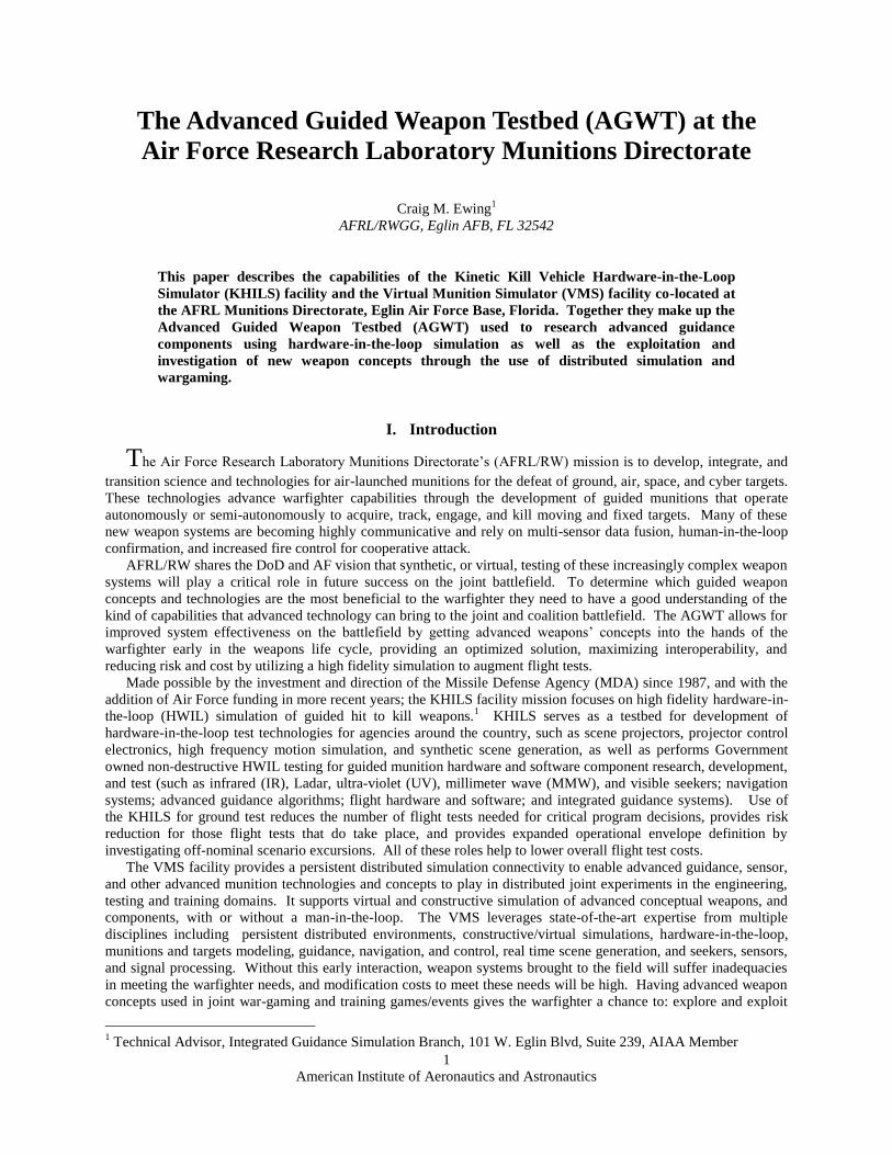
Figure 13. Eight-channel Ladar scene projector.
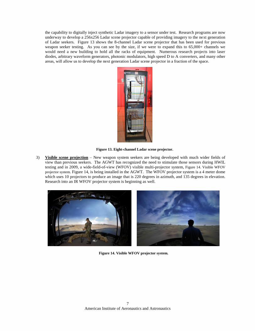
Figure 14. Visible WFOV projector system.
the capability to digitally inject synthetic Ladar imagery to a sensor under test. Research programs are now
underway to develop a 256x256 Ladar scene projector capable of providing imagery to the next generation
of Ladar seekers. Figure 13 shows the 8-channel Ladar scene projector that has been used for previous
weapon seeker testing. As you can see by the size, if we were to expand this to 65,000+ channels we
would need a new building to hold all the racks of equipment. Numerous research projects into laser
diodes, arbitrary waveform generators, photonic modulators, high speed D to A converters, and many other
areas, will allow us to develop the next generation Ladar scene projector in a fraction of the space.
3) Visible scene projection – New weapon system seekers are being developed with much wider fields of
view than previous seekers. The AGWT has recognized the need to stimulate those sensors during HWIL
testing and in 2009, a wide-field-of-view (WFOV) visible multi-projector system, Figure 14. Visible WFOV
projector system. Figure 14, is being installed in the AGWT. The WFOV projector system is a 4 meter dome
which uses 10 projectors to produce an image that is 220 degrees in azimuth, and 135 degrees in elevation.
Research into an IR WFOV projector system is beginning as well.

American Institute of Aeronautics and Astronautics
8
Figure 15. PACE control electronics.
Figure 16. Non-uniformity correction station.
4) Projector array control electronics - Through KHILS’ technology development efforts in array control
electronics, talented engineers have designed the PC-based Array Control Electronics or PACE.4 PACE,
see Figure 15, is an inexpensive, robust, and reconfigurable set of electronics that can support legacy,
current and upcoming emitter array projectors. The PACE electronics systems are manufactured and tested
in the KHILS facility and have been successfully transitioned to numerous MDA, Air Force, Army and
Navy test facilities.
F. Infrared Projector Characterization
KHILS has established a nationwide reputation as an expert in non-uniformity correction (NUC), see Figure 16,
of resistive array IR scene projectors. These types of projectors suffer from an inherent non-uniformity among the
individual elements. The uncorrected elements may exhibit 10-20% spatial variation when commanded with the
same drive voltage. Methods have been developed over the past decade for NUC of resistor array projectors. After
correction, the element response variation can be reduced to the order of a percent or two, depending mainly on the
NUC camera errors.5,6,7,8
G. Synthetic Scene Generation
To provide inputs to all of these different types of scene projectors, we have an extensive real-time synthetic
scene generation capability. The AGWT’s primary function relates to high fidelity end game simulations of visible,
infrared, MMW, and Ladar seekers and the closing guidance sequences require that KHILS engineers merge
aerodynamics, six-degree of freedom analysis, aerodynamic heating, and signature predictions in a real-time
sequence. The code used to generate these images in the AGWT is called the Real-Time Composite High Altitude
Missile Plume (RTC) code.

American Institute of Aeronautics and Astronautics
9
Boosting Theater Target Deploying Post-Boost Vehicle Strategic Reentry Vehicle
High Performance Fighter Twin Turbine Helicopter Supersonic Cruise Missile
Boosting Theater Target Deploying Post-Boost Vehicle Strategic Reentry Vehicle
High Performance Fighter Twin Turbine Helicopter Supersonic Cruise Missile
Figure 17. Air breathing and ballistic missile RTC outputs in various wavebands.
Figure 18. Ground and maritime RTC output in various wavebands.
RTC began as a code called Composite High Altitude Missile Plume (CHAMP)9, developed by KHILS in the
late 1980s as a tool to render complex targets, such as missiles with fins, multi-warhead post-boost vehicles, and
waking reentry vehicles. CHAMP incorporates the time-dependent signature phenomena, based on computed hard-
body thermal response due to radiation and convection heat loads. It also models external source effects, including
solar reflection, earth shine, and plume impingement. Over the years, the CHAMP code has been updated to include
modeling of tactical air breathing targets such as aircraft, cruise missiles, maritime, and ground based targets. It has
also been made to run real-time for use as RTC for performing HWIL simulations. Figure 17 shows examples of
RTC output for ballistic missiles and air breathing threats. Figure 18 shows some examples of maritime and ground
based target imagery generated with the RTC code.

American Institute of Aeronautics and Astronautics
10
Figure 19. Urban scene generation examples in various wavebands.
As urban combat has become an important part of the warfighter’s mission, the AGWT is developing a
capability to exercise advanced weapons with realistic synthetic urban imagery in real-time. The capability to
generate urban scenes as high fidelity, spectrally correct images has been completed under a Small Business
Innovative Research (SBIR) program with TerraSim using their product TerraTools®, see Figure 19. Work is
currently ongoing to merge the urban scene generation with RTC to provide a real-time capability for use in the
HWIL environment.
H. Environmental Chambers
Some weapon systems are designed to operate in unique operational backgrounds, or require special
environments for repeatable high fidelity ground testing. KHILS has several unique capabilities to provide the
appropriate operational environment for HWIL testing.
1) Cryogenic chamber - The first is the KHILS Vacuum Cold Chamber (KVACC), Figure 20. The KVACC
consists of a cooled optical collimator and source chamber inside a vacuum chamber in a class 1000 clean
room and has established the capability to perform IR scene projection for hardware-in-the-loop (HIL)
testing with significantly reduced IR backgrounds. The cold background of this system reduces the overall
thermal noise floor, thereby increasing the available dynamic range of the projection system. The all-
reflective optics in KVACC provides the capability of simultaneous mid-wave and long-wave IR scene
projection. A sensor chamber has been added to the main KVACC chamber, providing for testing of seeker
hardware and/or vacuum capable IR cameras. Also, a gaseous helium refrigeration system has been
installed, greatly reducing the logistics and operational overhead of dealing with LN2. The new
refrigeration system provides a chill-down capability to about 50 to 60 K. 10

American Institute of Aeronautics and Astronautics
11
Figure 20. Cryogenic chamber.
Figure 21. RF anechoic chamber.
2) RF environmental chamber - The AGWT also includes a 21x26x16 tall foot X-band anechoic chamber
located in a 100 DB shielded room to accommodate ground testing of RF systems, Figure 21. There is a
moveable flight table mount that allows a flight table to be inserted into the middle of the room for
articulation of test articles inside the chamber. There is an antenna array wall at the other end with access
to the RF chamber.
American Institute of Aeronautics and Astronautics
12
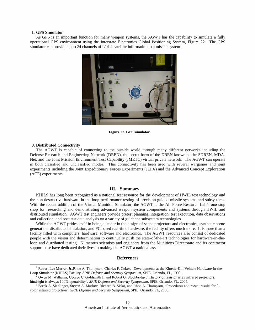
I. GPS Simulator
As GPS is an important function for many weapon systems, the AGWT has the capability to simulate a fully
operational GPS environment using the Interstate Electronics Global Positioning System, Figure 22. The GPS
simulator can provide up to 24 channels of L1/L2 satellite information to a missile system.
J. Distributed Connectivity
The AGWT is capable of connecting to the outside world through many different networks including the
Defense Research and Engineering Network (DREN), the secret form of the DREN known as the SDREN, MDA-
Net, and the Joint Mission Environment Test Capability (JMETC) virtual private network. The AGWT can operate
in both classified and unclassified modes. This connectivity has been used with several wargames and joint
experiments including the Joint Expeditionary Forces Experiments (JEFX) and the Advanced Concept Exploration
(ACE) experiments.
III. Summary
KHILS has long been recognized as a national test resource for the development of HWIL test technology and
the non destructive hardware-in-the-loop performance testing of precision guided missile systems and subsystems.
With the recent addition of the Virtual Munition Simulator, the AGWT is the Air Force Research Lab’s one-stop
shop for researching and demonstrating advanced weapon system components and systems through HWIL and
distributed simulation. AGWT test engineers provide pretest planning, integration, test execution, data observations
and collection, and post test data analysis on a variety of guidance subsystem technologies.
While the AGWT prides itself in being a leader in the design of scene projectors and electronics, synthetic scene
generation, distributed simulation, and PC based real-time hardware, the facility offers much more. It is more than a
facility filled with computers, hardware, software and electronics. The AGWT resources also consist of dedicated
people with the vision and determination to continually push the state-of-the-art technologies for hardware-in-the-
loop and distributed testing. Numerous scientists and engineers from the Munitions Directorate and its contractor
support base have dedicated their lives to making the AGWT a national asset.
References
1 Robert Lee Murrer, Jr.,Rhoe A. Thompson, Charles F. Coker, “Developments at the Kinetic-Kill Vehicle Hardware-in-the-
Loop Simulator (KHILS) Facility, SPIE Defense and Security Symposium, SPIE, Orlando, FL, 1999.
2 Owen M. Williams, George C. Goldsmith II and Robert G. Stockbridge,” History of resistor array infrared projectors:
hindsight is always 100% operability”, SPIE Defense and Security Symposium, SPIE, Orlando, FL, 2005. 3 Breck A. Sieglinger, Steven A. Marlow, Richard B. Sisko, and Rhoe A. Thompson, “Procedures and recent results for 2-
color infrared projection”, SPIE Defense and Security Symposium, SPIE, Orlando, FL, 2006.
Figure 22. GPS simulator.

American Institute of Aeronautics and Astronautics
13
4 George C. Goldsmith II, W. Larry Herald, Ricky A. Erickson, Walter S. Irvine Jr., Paul R. Mackin, Paul Bryant, Brian
Lindberg, “Setting the PACE in IRSP: A reconfigurable PC-based array control electronics system for infrared scene projection”,
SPIE Defense and Security Symposium, SPIE, Orlando, FL, 2003. 5 William M Meshell, Breck A. Sieglinger, Steven A. Marlow, August J. Huber, David R Forester, Michael K. Deiler,
“Nonuniformity Correction for Large Format Resistor Arrays”, SPIE Defense and Security Symposium, SPIE, Orlando, FL, 2008 6 Robert A. Joyce,
Leszek Świerkowski and Owen M. Williams,” Resistor array infrared projector nonuniformity correction:
search for performance improvement”, SPIE Defense and Security Symposium, SPIE 6208, April 2006, Orlando FL.
7 R. Bryan Sisko, Rhoe A Thompson, Steven A. Marlow, and Breck A. Sieglinger, “Resistor array waveband nonuniformity
measurements and RNUC band converter”, SPIE Defense and Security Symposium, April 2006, Orlando FL.
8 David S. Flynn, R. Bryan Sisko, Breck A. Sieglinger, and Rhoe A. Thompson, “Radiometrically calibrating spectrally
coupled 2-color projectors”, Conference on Technologies for Synthetic Environments: Hardware-in-the-Loop Testing VIII, SPIE
5092-15, April 2003.
9 Crow, D.R., Coker, C.F., “Composite hardbody and missile plume (CHAMP98) IR target scene generation program,” in
Technologies for Synthetic Environments: Hardware-in-the-Loop Testing III, Proceedings SPIE 3368, 1998.
10 Rhoe A. Thompson, William L. Herald, Thomas P. Bergin, Steven A. Marlow, Eric W. Glattke, “Advances in cryo-
vacuum test capabilities for dual-band sensors at the kinetic kill vehicle hardware-in-the-loop simulation (KHILS) facility”, SPIE
Defense and Security Symposium, April 2006, Orlando FL.