Embed Size (px)
Citation preview

AFRL-RQ-WP-TP-2012-0292
STRESS INTENSITY SOLUTIONS FOR CORNER AND THROUGH-THE-THICKNESS CRACKS AT A U-SHAPED NOTCH (PREPRINT) James A. Harter Sustainable Structures Branch Structures Division
SEPTEMBER 2012
Approved for public release; distribution unlimited.
See additional restrictions described on inside pages
STINFO COPY
AIR FORCE RESEARCH LABORATORY AEROSPACE SYSTEMS DIRECTORATE
WRIGHT-PATTERSON AIR FORCE BASE, OH 45433-7542 AIR FORCE MATERIEL COMMAND
UNITED STATES AIR FORCE
REPORT DOCUMENTATION PAGE Form Approved
OMB No. 0704-0188
The public reporting burden for this collection of information is estimated to average 1 hour per response, including the time for reviewing instructions, searching existing data sources, searching existing data sources, gathering and maintaining the data needed, and completing and reviewing the collection of information. Send comments regarding this burden estimate or any other aspect of this collection of information, including suggestions for reducing this burden, to Department of Defense, Washington Headquarters Services, Directorate for Information Operations and Reports (0704-0188), 1215 Jefferson Davis Highway, Suite 1204, Arlington, VA 22202-4302. Respondents should be aware that notwithstanding any other provision of law, no person shall be subject to any penalty for failing to comply with a collection of information if it does not display a currently valid OMB control number. PLEASE DO NOT RETURN YOUR FORM TO THE ABOVE ADDRESS.
1. REPORT DATE (DD-MM-YY) 2. REPORT TYPE 3. DATES COVERED (From - To)
September 2012 Journal Article Preprint 01 October 2009 – 08 December 2010 4. TITLE AND SUBTITLE
STRESS INTENSITY SOLUTIONS FOR CORNER AND THROUGH-THE-THICKNESS CRACKS AT A U-SHAPED NOTCH (PREPRINT)
5a. CONTRACT NUMBER
In-house 5b. GRANT NUMBER
5c. PROGRAM ELEMENT NUMBER
62201F 6. AUTHOR(S)
James A. Harter
5d. PROJECT NUMBER
N/A 5e. TASK NUMBER
N/A 5f. WORK UNIT NUMBER
Q05K 7. PERFORMING ORGANIZATION NAME(S) AND ADDRESS(ES) 8. PERFORMING ORGANIZATION
REPORT NUMBER
Sustainable Structures Branch (AFRL/RQSS) Structures Division Air Force Research Laboratory, Aerospace Systems Directorate Wright-Patterson Air Force Base, OH 45433-7542 Air Force Materiel Command, United States Air Force
AFRL-RQ-WP-TP-2012-0292
9. SPONSORING/MONITORING AGENCY NAME(S) AND ADDRESS(ES) 10. SPONSORING/MONITORING AGENCY ACRONYM(S)
Air Force Research Laboratory Aerospace Systems Directorate Wright-Patterson Air Force Base, OH 45433-7542 Air Force Materiel Command United States Air Force
AFRL/RQSS
11. SPONSORING/MONITORING AGENCY REPORT NUMBER(S)
AFRL-RQ-WP-TP-2012-0292
12. DISTRIBUTION/AVAILABILITY STATEMENT
Approved for public release; distribution unlimited.
13. SUPPLEMENTARY NOTES
PA Case Number: 88ABW-2011-0290; Clearance Date: 25 Jan 2011. This technical paper contains color.
14. ABSTRACT
Stress intensity factor solutions for corner and through cracks growing from a u-shaped edge notch are required to improve the accuracy of damage tolerance analyses for continuing damage scenarios. Closed-form K-solutions for through-the-thickness and corner cracks under remote axial loading were developed using 3-D finite element (FE) models for wide plates. Finite width corrections were determined based on FE models for a wide range of finite plate geometries. The finite width models included boundary conditions with and without far edge constraints as an option to account for in-plane bending due to geometric asymmetry. The resulting solutions are valid for notch depths resulting from equivalent hole edge distances (e/D) from 0.0 to 49.5.
15. SUBJECT TERMS
stress intensity factor, continuing damage, notch
16. SECURITY CLASSIFICATION OF: 17. LIMITATION OF ABSTRACT:
SAR
18. NUMBER OF PAGES
24
19a. NAME OF RESPONSIBLE PERSON (Monitor)
a. REPORT Unclassified
b. ABSTRACT Unclassified
c. THIS PAGE Unclassified
James A. Harter 19b. TELEPHONE NUMBER (Include Area Code)
N/A Standard Form 298 (Rev. 8-98)
Prescribed by ANSI Std. Z39-18
1 Approved for public release; distribution unlimited.
Stress Intensity Solutions for Corner and Through-the-Thickness Cracks at a U-Shaped Notch
JAMES A. HARTER
Sustainable Structures Branch, United States Air Force Research Laboratory, Wright-Patterson AFB, OH
ABSTRACT
Stress intensity factor solutions for corner and through cracks growing from a u-shaped edge notch are required to improve the accuracy of damage tolerance analyses for continuing damage scenarios. Closed-form K-solutions for through-the-thickness and corner cracks under remote axial loading were developed using 3-D finite element (FE) models for wide plates. Finite width corrections were determined based on FE models for a wide range of finite plate geometries. The finite width models included boundary conditions with and without far edge constraints as an option to account for in-plane bending due to geometric asymmetry. The resulting solutions are valid for notch depths resulting from equivalent hole edge distances (e/D) from 0.0 to 49.5.
Keywords Stress Intensity Factor Solution Continuing Damage Cracked Notch U-Shaped Notch Slotted Notch
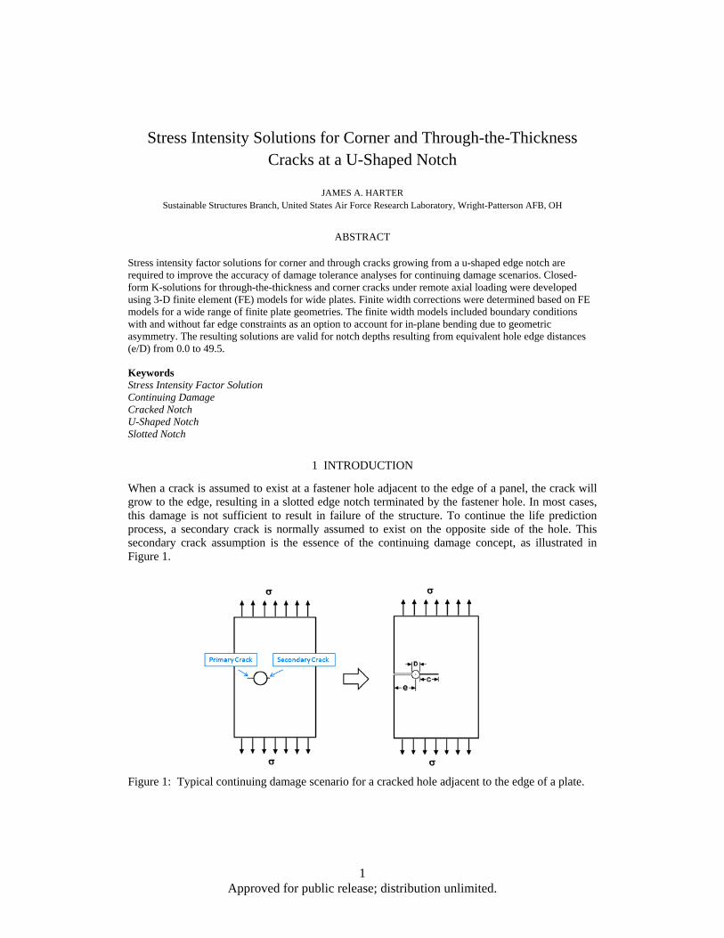
1 INTRODUCTION
When a crack is assumed to exist at a fastener hole adjacent to the edge of a panel, the crack will grow to the edge, resulting in a slotted edge notch terminated by the fastener hole. In most cases, this damage is not sufficient to result in failure of the structure. To continue the life prediction process, a secondary crack is normally assumed to exist on the opposite side of the hole. This secondary crack assumption is the essence of the continuing damage concept, as illustrated in Figure 1.
Figure 1: Typical continuing damage scenario for a cracked hole adjacent to the edge of a plate.

2 Approved for public release; distribution unlimited.
The U.S. Air Force defines continuing damage [1] as the assumption of a primary crack (typically 0.05 in.) growing from one side of a hole with a secondary (typically 0.005 in.) crack growing simultaneously on the opposite side of the hole. Initial through the thickness cracks are assumed for thin skin structures, and corner cracks are normally used for thick sections. Stress intensity (K) solutions are available for non-symmetric corner and through cracks at a fastener hole, but these solutions are only valid until the primary crack grows to the edge of a panel. The secondary crack will continue to grow, but the K-solution must reflect the change in geometry once the ligament between the hole and the free edge is severed.
Closed-form K-solutions are available for a through cracked elliptical notch in a semi-infinite plate. However, it was determined (based on notch stress concentration factors) that these solutions are approximately 10-15% unconservative when compared to a U-shaped, or slotted notch, which is more representative of the continuing damage geometry as shown in Figure 2.
Figure 2: Elliptical vs. u-shaped notch geometry and associated stress concentration factors.
This paper will document the development of general closed-form K-solutions for corner and through-the-thickness cracks growing from edge notches to improve the accuracy of continuing damage crack growth life predictions.
2 APPROACH
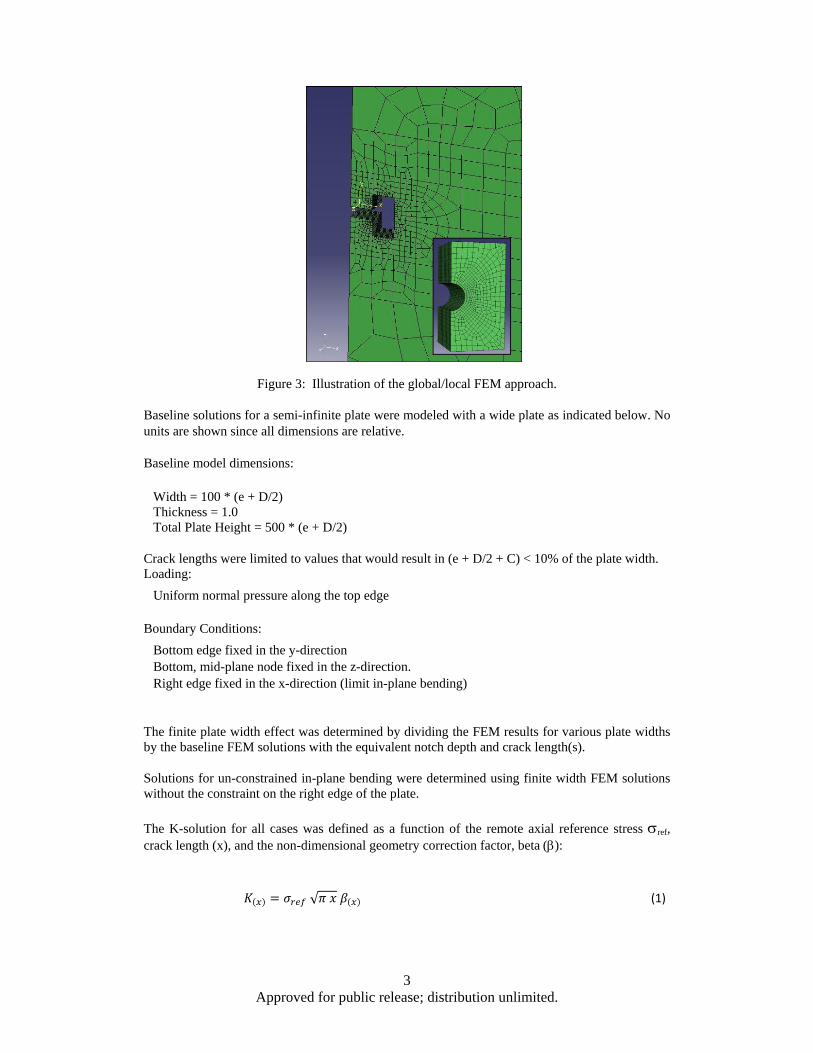
Three dimensional FE models were used to calculate stress intensity factors for the through and corner cracked notch geometries. The FE analysis program, Abaqus [2], was used to create and analyze all of the structural models required for this effort. The stress intensity solutions were obtained using FRANC 3D/NG [3] to insert a crack in a local model surrounding the notch as indicated in Figure 3.
3 Approved for public release; distribution unlimited.
Figure 3: Illustration of the global/local FEM approach.
Baseline solutions for a semi-infinite plate were modeled with a wide plate as indicated below. No units are shown since all dimensions are relative.
Baseline model dimensions:
Width = 100 * (e + D/2) Thickness = 1.0 Total Plate Height = 500 * (e + D/2)
Crack lengths were limited to values that would result in (e + D/2 + C) < 10% of the plate width. Loading:
Uniform normal pressure along the top edge
Boundary Conditions:
Bottom edge fixed in the y-direction Bottom, mid-plane node fixed in the z-direction. Right edge fixed in the x-direction (limit in-plane bending)
The finite plate width effect was determined by dividing the FEM results for various plate widths by the baseline FEM solutions with the equivalent notch depth and crack length(s).
Solutions for un-constrained in-plane bending were determined using finite width FEM solutions without the constraint on the right edge of the plate.
The K-solution for all cases was defined as a function of the remote axial reference stress ref, crack length (x), and the non-dimensional geometry correction factor, beta ():
√ (1)
4 Approved for public release; distribution unlimited.
The reference stress for all solutions in this paper is the gross remote tension stress applied along the top edge of the plate. For clarity and consistency with standard practice, the crack lengths in the plate width direction were defined as the c-dimension, and cracks in the plate thickness direction were defined as the a-dimension. 2.1 Through‐the‐thickness crack approach The 2-D (Plane Stress) solution was determined from the 3-D FEM results using the standard relationship between the plane stress and plane strain K-solution.
√1 (2)
This approach was verified for an edge crack in a semi-infinite plate using the same FEM dimensions, loading, and boundary conditions used for the continuing damage models substituting the edge crack length in place of the notch depth. The results were within 1% of the well known (2-D) edge crack solution [4].
1.122 (3)
The notched solution for the continuing damage case is known when the crack length approaches both zero and infinity. As the crack length approaches zero, the beta value converges to the stress concentration factor for the u-shaped notch [5] multiplied by the edge crack correction.
1.122
(4)
As the crack length goes to infinity, the solution converges to the edge crack solution in a semi-infinite plate. Since the through-the-thickness crack length (c) for the continuing damage case is measured from the edge of the hole, a correction was applied to the beta solution to obtain the equivalent edge crack solution.
.
/ (5)
The notch depth (N) was simply defined as the hole edge distance (e) plus the hole radius (R = D/2). Wide plate FEM K-solutions were calculated for several ratios of hole radius to notch depth (R/N).
R/N = 0.1, 0.2, 0.333, 0.5, and 1.0
Crack lengths were normalized by dividing each crack length by the sum of the crack length and the notch depth. This allowed the results for all notch depths to be plotted together so that data for other notch depths could be determined by interpolation. It should be noted that the -solution for R/N=0.0 is the equivalent semi-infinite plate edge crack solution.
The combinations of plate width, hole diameter, and edge distance used to determine the finite width correction are indicated in Table 1 and Table 2.

5 Approved for public release; distribution unlimited.
Table 1: Finite width Geometries for D=0.5.
Table 2: Finite width geometries for D=0.25
2.2 Corner Crack Approach The corner cracked solution was based on the framework of the Newman and Raju closed-form K-solution for an elliptic, corner cracked hole under remote tension loading [6].
/ (6)
(7)
As noted in reference [6], the functions, G1G2…Gn, are used to fine-tune the solution. The functions, G1, G2, and G3, were modified as required to obtain a close fit (5%) to the FEM results. Wide plate FEM K-solutions for the corner cracked hole case were calculated for a number of R/N values.
R/N = 0.1, 0.2, 0.333, and 1.0
The function, G2, generally accounts for the unflawed stress distribution in both crack directions. G3 is used to make adjustments for crack shape (a/c) and percent of plate thickness penetrated
6 Approved for public release; distribution unlimited.
(a/t). A minor adjustment to G1a was required to force the solution to converge in both directions as the crack length goes to zero.
For the c-dimension, the wide plate beta values obtained for the through crack were used as the basis for G2c.
. (8)
This provided a means to capture the effect of a given notch geometry on the local stress distribution in the c-direction. A relationship for G2a was needed that would allow G3a (required to match the FEM results) to be within 5% for all notch depths. The closed-form equation for G2a was determined by iteration using the FEM results for each notch depth.
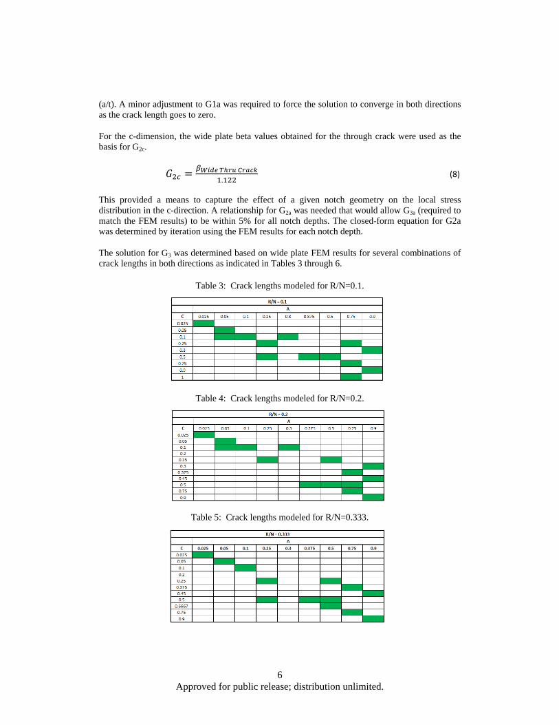
The solution for G3 was determined based on wide plate FEM results for several combinations of crack lengths in both directions as indicated in Tables 3 through 6.
Table 3: Crack lengths modeled for R/N=0.1.
Table 4: Crack lengths modeled for R/N=0.2.
Table 5: Crack lengths modeled for R/N=0.333.
7 Approved for public release; distribution unlimited.
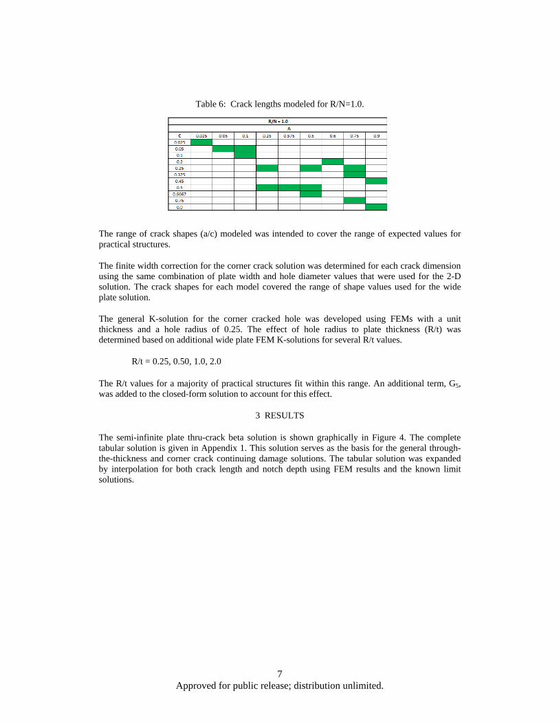
Table 6: Crack lengths modeled for R/N=1.0.
The range of crack shapes (a/c) modeled was intended to cover the range of expected values for practical structures.
The finite width correction for the corner crack solution was determined for each crack dimension using the same combination of plate width and hole diameter values that were used for the 2-D solution. The crack shapes for each model covered the range of shape values used for the wide plate solution.
The general K-solution for the corner cracked hole was developed using FEMs with a unit thickness and a hole radius of 0.25. The effect of hole radius to plate thickness (R/t) was determined based on additional wide plate FEM K-solutions for several R/t values.
R/t = 0.25, 0.50, 1.0, 2.0
The R/t values for a majority of practical structures fit within this range. An additional term, G5, was added to the closed-form solution to account for this effect.
3 RESULTS
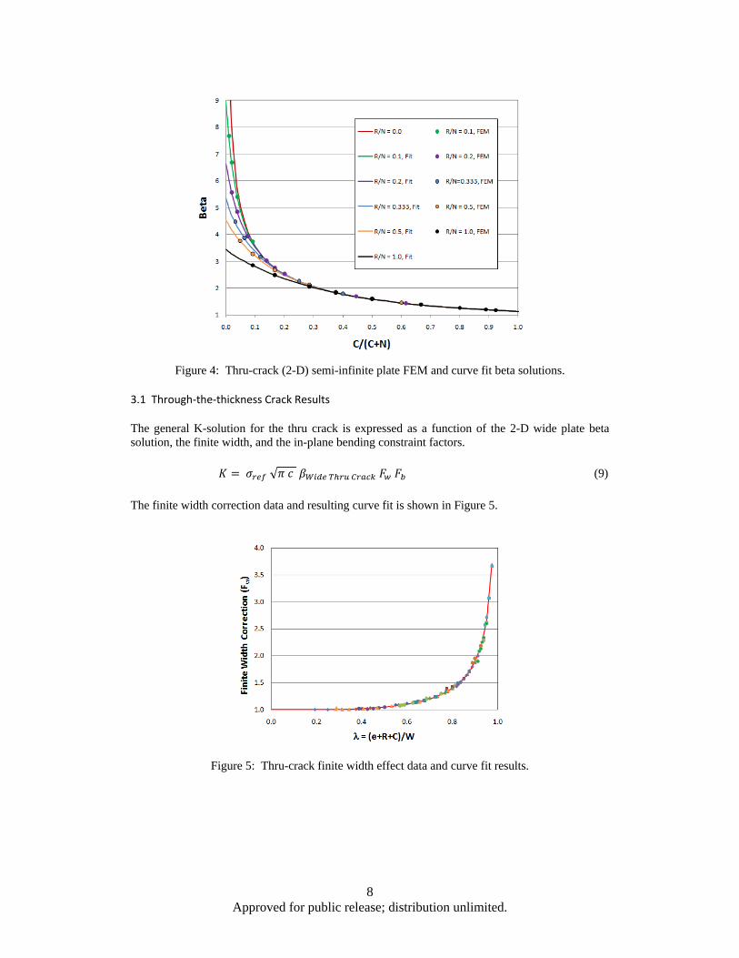
The semi-infinite plate thru-crack beta solution is shown graphically in Figure 4. The complete tabular solution is given in Appendix 1. This solution serves as the basis for the general through-the-thickness and corner crack continuing damage solutions. The tabular solution was expanded by interpolation for both crack length and notch depth using FEM results and the known limit solutions.
8 Approved for public release; distribution unlimited.
Figure 4: Thru-crack (2-D) semi-infinite plate FEM and curve fit beta solutions. 3.1 Through‐the‐thickness Crack Results
The general K-solution for the thru crack is expressed as a function of the 2-D wide plate beta solution, the finite width, and the in-plane bending constraint factors.
√ (9)
The finite width correction data and resulting curve fit is shown in Figure 5.
Figure 5: Thru-crack finite width effect data and curve fit results.

9 Approved for public release; distribution unlimited.
.
(10)
Since the baseline FEM solutions were constrained along the right edge, the bending correction is required to obtain the K-solution when this constraint is removed.
Figure 6: Thru-crack bending correction data and curve fit results.
1 0.26 4.4 11.3 8.2 18.5 69.0 (11)
3.2 Corner Crack Results
As stated previously, the corner crack solution was based on the Newman and Raju corner cracked hole solution framework.
/ (12)
(13)
The majority of the parameters were used without changes and are given here as a convenience for the reader.
Fora/c 1
1.13 0.09 / (14)
.
. /0.54 (15)

10 Approved for public release; distribution unlimited.
0.5.
. /14 1 / (16)
1 0.1 0.35 / (17)
/ (18)
1.0 (19)
1.0 1.464 / . (20)
Fora/c 1
/ 1.0 0.04 / (21)
0.2 / (22)
0.11 / (23)
1 0.1 0.35 / / (24)
1.0 (25)
/ (26)
1.0 1.464 / . (27) The remaining parameters were modified as required to provide the best fit to the FEM results.
1.0 0.0699 / (28)
. (29)
0.985. .
. / . (30)

11 Approved for public release; distribution unlimited.
Figure 7: Corner crack G3c FEM data and curve fit results.
Fora/c 1
0.985 0.087 / . 0.29 / 0.11 / .
0.05 / (31)
Fora/c 1
1.5585 0.66 / . 0.29 / 0.11 / .
0.05 / (32)
Figure 8: Corner Crack G3a FEM data and curve fit results.

12 Approved for public release; distribution unlimited.
Fora/c 1
0.735. . / . /
. / . . / . 0.625 / (33)
Fora/c 1
0.735. . / . /
. / . . / 0.625 / (34)
Figure 9: Corner Crack G5c FEM data and curve fit results.
1. / .
. / . 0.035 1 /.
(35)
Figure 10: Corner Crack G5a FEM data and curve fit results.

13 Approved for public release; distribution unlimited.
0.5/ .
. . /0.8 . / / 0.25 / (36)
Figure 11: Corner Crack Fwc data and curve fit results.
.
(37)
Figure 12: Corner Crack Fwa data and curve fit results.
.
(38)

14 Approved for public release; distribution unlimited.
The in-plane bending correction is based on the curve-fit for the through crack case (Fb, Section
3.1) where the function, , is defined for each crack direction.
/ (39)
/ (40)
/ (41)
/ (42)
Figure 13: Corner Crack in-plane bending correction error vs. c-length to un-cracked net section ratio.
4 VERIFICATION
The 2-D tabular semi-infinite plate beta solution matrix was expanded to include a wide range of notch depths and a large number of crack lengths. The values were selected so that reasonably accurate (within 5%) solution for a given geometry could be obtained using linear interpolation.
Since the proposed through-the-thickness and corner cracked solutions were developed by curve fitting the baseline FEM results, good agreement for all baseline notch depths would be expected. The solutions were verified for a notch depth that was significantly deeper (R/N=0.03) than all of the baseline FEM models. A limited number of crack lengths were analyzed since CPU run times were approximately 12 hours for each case due to the size of the models.
15 Approved for public release; distribution unlimited.
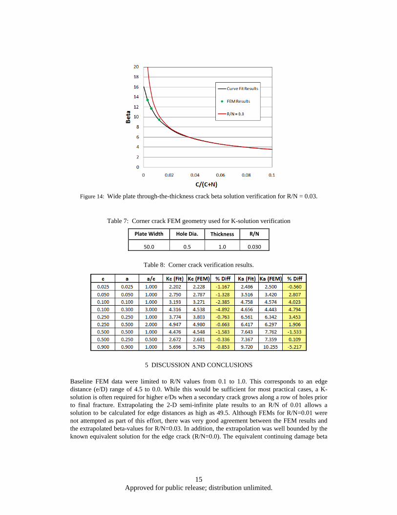
Figure 14: Wide plate through-the-thickness crack beta solution verification for R/N = 0.03.
Table 7: Corner crack FEM geometry used for K-solution verification
Plate Width Hole Dia. Thickness R/N
50.0 0.5 1.0 0.030
Table 8: Corner crack verification results.
5 DISCUSSION AND CONCLUSIONS
Baseline FEM data were limited to R/N values from 0.1 to 1.0. This corresponds to an edge distance (e/D) range of 4.5 to 0.0. While this would be sufficient for most practical cases, a K-solution is often required for higher e/Ds when a secondary crack grows along a row of holes prior to final fracture. Extrapolating the 2-D semi-infinite plate results to an R/N of 0.01 allows a solution to be calculated for edge distances as high as 49.5. Although FEMs for R/N=0.01 were not attempted as part of this effort, there was very good agreement between the FEM results and the extrapolated beta-values for R/N=0.03. In addition, the extrapolation was well bounded by the known equivalent solution for the edge crack (R/N=0.0). The equivalent continuing damage beta

16 Approved for public release; distribution unlimited.
solution for an edge crack must be corrected since the crack length is measured from the edge of the notch. The 2-D semi-infinite plate beta table indicates that the solution is nearly converged to the equivalent edge crack solution for notch depths beyond R/N=0.01. The in-plane bending correction for the corner crack solution is complicated by the out-of-plane bending effect of the corner crack geometry. The proposed corner crack bending correction is in good agreement (< 6%) with the FEM results when the crack length in the c-direction is less than 20% of the un-cracked net section width. There are few practical cases that would be affected by this limitation. The proposed closed-form solutions are offered as a reasonably accurate alternative to the use of detailed FEM K-solutions for continuing damage crack growth life prediction.
References
[1] U.S. Department of Defense, (1998), Joint Service Specificaion Guide - Structures (JSSG-2006), ASC/ENSI, Wright-Patterson AFB, OH.
[2] Abaqus is a general purpose FE analysis program developed by Dassault Systemes, Simulia Limited
[3] FRANC3D/NG is a crack growth simulation program developed by Fracture Analysis Consultants, Inc., Ithaca, NY
[4] Tada, H., Paris, P.C., and Irwin, G.R., "The Stress Analysis of Cracks Handbook," Second Edition, p. 2.11, Paris Productions, Inc., St Louis, MO, 198
[5] Peterson, R.E., “Stress Concentration Factors,” Fig. 15, P. 33, John Wiley & Sons, Inc., 1974
[6] Newman, J.C., and Raju, I.S., "Stress Intensity Factor Equations for Cracks in Three-Dimensional Bodies Subjected to Tension and Bending Loads," Chapter 9, Computational Methods in the Mechanics of Fracture, Elsvier Science Publishers B.V., 1986
17 Approved for public release; distribution unlimited.
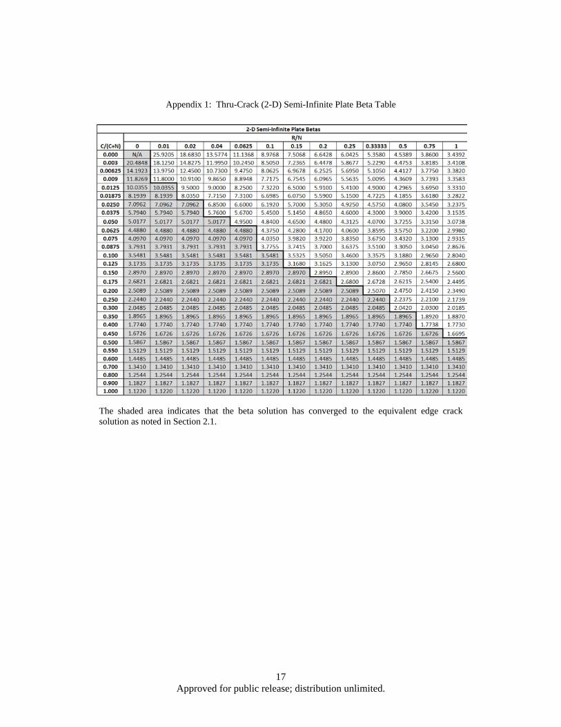
Appendix 1: Thru-Crack (2-D) Semi-Infinite Plate Beta Table
The shaded area indicates that the beta solution has converged to the equivalent edge crack solution as noted in Section 2.1.