Embed Size (px)
Citation preview

AFOSRlM- 88-0 662C-" DTIC FILE COPy
THE MEASUREMENT AND PREDICTION OFI ROTORDYNAMIC FORCES FOR
. ,LABYRINTH SEALS
prepared by
D. W. ChildsD. L. Rhode
prepared for
Air Force Office of Scientific ResearchBoiling Air Force Base
Washington, D. C. 20332
Contract F49620-82-K083'
DTICELECTE
JUN 2 9 1988Turbomachinery Laboratory
Mechanical Engineering Department G ,Texas A&M University
College Station, Texas 77843
March 1988
* Apprrvmy fo- pubkc relocus;
---ttf ti. - f'r -- t #)d
. -.- .. ,-. _t. . . . ,, .- .- .. 2-. , *. -. . --. .-f. ft . . -, . ._, . . ,... ........ ,..._.. . -..- . , ..- , , , ,, .-- .5

SEU VCASFCATION O0 Tft*6 1
%. rREPORT DOCUMENTATION PAGE 4b -14 7&REPORT SECURITY LSIF C IN 1b. RESTRICTIVE MARKCINGS
* 2. SECURITY CLASSIFi kiONii AurmoRITY 3. OISTRIBUTION/AVAI LABILITY OF REPORTIUnclassified12b. OIECLASSIFICATION/OOWNGRAOING SCHIEDULE ~ ~'\\\'\V~C
/ . PERFORMING ORGANIZATION REPORT NUMBERAS) 5. MONITORING ORGANIZATION REPC.RT NUMBER(S)
6NAME OF PERFORMING ORGANIZATION 6b. OFFICE SYMBOL 74L NAME OF MONITORING 88GAN 0662OTexas A&M University (IepicbaI6. ADDRESS (City. State and ZIP Coae 7b. ADDRESS (City. Stae and ZIP Code)
College Station, Texas 77843-3123C(N Lc
12.DPER Sit.SONALan AZMO IS) a 0 ORE FFNIGMS
TIEW hild And D.L.e RhdeDC 203 ELMNNQ NONoN.
"TH MESUE.N SUPLMNTR NOTATIOND
L Rotrdnami FRMorcesT123/ 18, MARCH k 7~ 1 A
19. ABSTRACT ICniu IT JECTr TRM necesoary ond identif if R&iocftr an um rbyblckn
%I I _I Measurements of rotordynamic (stiffness and damping) coefficients andleakage characteristics were completed for labyrinth-rotor/hofleycombe-
Istator seals. Comparisons to labyrinth-rotor/smooth-stator seals showedIno stability improvements. Tests were also carried out on smooth-rotor/
honeycornbe- stator seals and demonstrated superior stability and, leakageperformance for this type of seal if the entering flow is pre-rotated inthe direction of rotation.
A new "bulk-flow" theory for labyrinth seals has been developed and its
* predictions compare well with measured results for tooth-on-rotor labyrinths.
Also, a more sophisticated model was developed which solves the -* ReynolIds- averaged Navier-Stokes equations for compressible flow)~ PredictionE
j. :)S7Rj8LjTiON/AVAgI...8ILITY OF ABSTRPACT 2 BT
UNCLASSIFIEO/UNLIMITED : SAME AS APT IeC USERS
22. N4AME OF RESPONSiBLE INDIVIOUAL 22b. TELEPHONE NUMBER 2
2c. OFFICE SYMBOL
)0 FORM 1472, 83 APR EOITiC'q OF I iA 71 15 )SOLETF O~p -
...... 0

THE MEASUREMENT AND PREDICTION OFROTORDYNAMIC FORCES FOR
LABYRINTH SEALS
prepared by
D. W. ChildsD. L. Rhode
prepared for
Air Force Office of Scientific ResearchBoiling Air Force Base
Washington, D. C. 20332
Contract F49620-82-K0083
Turbomachinery LaboratoryMechanical Engineering Department
Texas A&M UniversityCollege Station, Texas 77843
March 1988

TABLE OF CONTENTS
I. Experimental Measurements and Bulk-Flow Developments
H. Finite Difference Developments and Results
Appendix A
Appendix B
'C"
,'.
C Accession ForP, - NTIS GRA&I
N"P'CTED
DTIC TABUna nou nced T
I V I st r at . c ,t '
. . r-- ... -C- . . .... --C C
!L i s t..... ... I
r. I %

-A FINAL REPORTAFOSR CONTRACT NO F49620-82-K-0033
9/1/82 through 12/31/87
L Experimental Measurements and "Bulk Flow" Model Developments - D. Childs
The work conducted in this portion of the research contract has consisted of thefollowing tasks:
(a) the development of a facility and apparatus for measuring the leakage, axial pres-sure profiles, and rotordynamic (stiffness and damping) coefficients of labyrinthseals,
(b) the measurement of the test data cited above for a range of labyrinth-seal con-figurations, and
U (c) the development and validation of "bulk-flow" models for the prediction of leakageand rotordynamic coefficients of labyrinth seals.
All of these objectives have been met in full and are documented in the following journalpublications:
o Childs, D. W. and Scharrer, J. K., "Experimental Rotordynamic Coefficient andResults for Teeth-On-Rotor and Teeth-On-Stator Labyrinth Gas Seals," ASMETrans. J. of Engineering for Gas Turbine and Power, Vol. 108, October 1986,pp. 599-604.
o Childs, D. W., Nelson, C. E., Nicks, C., Scharrer, J., Elrod, D., and Hale, K.,WIl "Theory Versus Experiment for the Rotordynamic Coefficients of Annular Gas
Seals: Part 1-Test Facility and Apparatus", ASME Transaction Journal of Ti-bology, July 1986, Vol. 108, pp. 426-432.
o Nelson, C., Childs, D., Nicks, C., Elrod, D., and Hale, K., "Theory Versus Exper-iment for the Rotordynamic Coefficients of Annular Gas Seals: Part 2-Constant-3 Clearance and Convergent- Tapered Geometry," ASME Transaction Journal ofTribology, July 1986, Vol. 108, pp. 433-438.
o Childs, D., and Scharrer, J., "An Iwatsubo-Based Solution for Labyrinth Seals -Comparison to Experimental Results," ASME Transaction Journal of Engineer-ing for Gas Turbine and Power, April 1986, Vol. 108, pp. 325-331.
o Childs, D. and Elrod, D., "Rotordynamic Coefficient and Leakage Test Resultsfor Interlock and Tooth-on-Stator Labyrinth Seals," accepted for presentation atthe ASME International Gas Turbine Conference, Amsterdam, The Netherlands,under review consideration ASME Trans. for Power.
*%0!. .

-W%"r-w -.
H. Finite Difference Developments and Results - D. Rhode
This portion of the research program involved the following tasks:
(a) the development of a 3-D finite difference computer code, using a generalizedbody-fitted coordinate system, for predicting forces as well as the distribution ofvarious other flowfield quantities
(b) the development of a procedure for calculating the rotordynamic force for a sealwith any arbitrary number of cavities at an affordable CPU expenditure
(c) the computation of forces at various operating conditions
V These objectives have been met and are documented in the following:* Rhode, D. L. and Hensel, S. J., "Three-Dimensional Computation of Rotordy-
namic Force Distributions in a Labyrinth Seal," accepted for presentation at theASME/AIAA First National Fluid Dynamics Congress, Cincinnati, OH, 24-28July 1988.
* Rhode, D. L. and Hensel, S. J., "Labyrinth Seal Rotordynamic Forces PredictedZ: with a Three-Dimensional Navier-Stokes Computer Code," accepted for presenta-
tion at the 24th AIAA/ASEE/ASME/SAE Joint Propulsion Conference, Boston,MA, 11-14 July 1988.
* Rhode, D. L. and Nail, G. H., "Computation of Cavity-By-Cavity Flow Devel-opment in Generic Labyrinth Seals," submitted for presentation at the ASMEInternational Computers in Engineering Conference, San Francisco, CA, 31 July- 3 August 1988.
* Rhode, D. L. and Sobolik, S. R., "Simulation of Subsonic Flow Through a GenericLabyrinth Seal," ASME Trans. Journal of Engineering for Gas Turbines andPower, October 1986, Vol. 108, pp. 674-680.
* Rhode, D. L., Demko, J. A., Traegner, U. K., Morrison, G. L. and Sobolik, S. R.,"Prediction of Incompressible Flow in Labyrinth Seals," ASME Trans. Journal
. of Fluids Engineering, March 1986, Vol. 108, pp. 19-25.
Appendix B contains three of the most recent papers:* . Rhode, D. L. and Hensel, S. J., "Three-Dimensional Computation of Rotordy-
namic Force Distributions in a Labyrinth Seal," accepted for presentation at theASME/AIAA First National Fluid Dynamics Congress, Cincinnati, OH, 24-28
r...>.July 1988.
, Rhode, D. L. and Hensel, S. J., "Labyrinth Seal Rotordynamic Forces Predicted* with a Three-Dimensional Navier-Stokes Computer Code," accepted for presenta-
tion at the 24th AIAA/ASEE/ASME/SAE Joint Propulsion Conference, Boston,11-14 July 1988.
-"Rhode, D. L. and Nail, G. H., "Computation of Cavity-By-Cavity Flow Devel-opment in Generic Labyrinth Seals," submitted for presentation at the ASME
5 International Computers in Engineering Conference, San Francisco, CA, 31 July- 3 August 1988.
The following students have participated in this portion of the AFRAPT program:Steve Sobolik, Steve Hensel, Greg Nail, and Robert Hibbs. Steve Hensel worked at Garrett,one summer, finished his M. S. Thesis in December 1987 and is continuing his studies for aPh.D. A summer position was not available in time for Steve Sobolik and Greg Nail. Stevefinished his M. S. Thesis in August 1984 and went to work for Sandia National Labs. Gregfinished his M. S. Thesis in December 1987 and is continuing his education for the Ph.D.degree. Robert Hibbs worked last summer at United Technologies in East Hartford andwill soon finish his M. S. Thesis.
We are grateful for the sponsorship of this research program by AFOSR. As with thetest facility, the computational capability continues to be unique throughout the world.The value of this widely applicable predictive capabi!ity has clearly been demonstrated.Also, previously unavailable values of various shear stress quantities have been computed,which were particularly useful in refining the bulk-flow model mentioned in the previoussection.
Further work is important and should include an analysis of the effect of geometricconfiguration including stepped seals, as well as the effect of rotor orbits whose centers areeccentric with respect to the housing.
..................................

W4 4
Copies of the three most-recent publications are included in Appendix A.
e * Hawkins, L., Childs, D., and Hale, K., "Experimental Results for Labyrinth GasSeals with Honeycomb Stators: Comparisons to Smooth-Stator Seals and Theo-retical Predictions," submitted for the 1988 ASME-ASLE Joint Tribology Con-ference and ASME Journal of Tribology.
e Scharrer, J., "Theory versus Experiment for the Rotordynamic Coefficients ofLabyrinth Gas Seals: Part I - A Two Control Volume Model," Rotating MachineryDynamics, Vol. 2, ASME 1987, pp. 427-434, accepted for presentation, ASMEJournal of Vibration, Acoustics, Stress, and Reliability in Design.
J Childs, D. and Scharrer, J., "Theory Versus Experiment for the RotordynamicCoefficients of Labyrinth Gas Seals: Part II - A Comparison to Experiment,"Rotating Machinery Dynamics, Vol. 2, ASME 1987, pp. 427-434, accepted for
Spresentation, ASME Journal of Vibration, Acoustics, Stress, and Reliability inDesign.
The AFRAPT participation in this program has included the students: Joseph Schar-rer and Lawrence Hawkins. Joe worked at G.E. Lynn during the summer, completed hisPh.D. in January 1987 and is continuing to work in rotating machinery with Rocketdyne.Larry worked for Garrett during two summers, completed his M.S. degree in January 1988,and is also going to work for Rocketdyne.
The support provided by AFOSR is deeply appreciated. The test apparatus we havedeveloped with AFOSR support continues to be unique in the world. The test resultsand models have been of extraordinary value in resolving rotordynamics stability issuesand have been used directly to develop higher-performance commercial turbomachinery.Considerable work remains to be done! No data or models are available yet for steppedseals, see-through labyrinth seals at reduced L/D ratios, brush seals, etc.
S2
-....... . . . . . .
.".. . . . . . . . . . . . .
Appendix A
Hawkins, L., Childs, D., and Hale, K., "Experimental Results for Labyrinth Gas Seals withHoneycomb Stators: Comparisons to Smooth-Stator Seals and Theoretical Predictions,"submitted for the 1988 ASME-ASLE Joint Tribology Conference and ASME Journal ofTribology.
Scharrer, J., "Theory versus Experiment for the Rotordynamic Coefficients of LabyrinthGas Seals: Part I - A Two Control Volume Model," Rotating Machinery Dynamics, Vol. 2,ASME 1987, pp. 427-434, accepted for presentation, ASME Journal of Vibration, Acous-tics, Stress, and Reliability in Design.
Childs, D. and Scharrer, J., "Theory Versus Experiment for the Rotordynamic Coefficientsof Labyrinth Gas Seals: Part II - A Comparison to Experiment," Rotating MachineryDynamics, Vol. 2, ASME 1987, pp. 427-434, accepted for presentation, ASME Journal of
-* Vibration, Acoustics, Stress, and Reliability in Design.
'a
V
4-

EXPERIMENTAL RESULTS FOR LABYRINTH GAS SEALS
WITH HONEYCOMB STATORS: COMPARISONS TO
SMOOTH-STATOR SEALS AND THEORETICAL PREDICTIONS'
LARRY HAWKINS, MEMBER TECHNICAL STAFFROCKETDYNE DIVISION, ROCKWELL INTERNATIONAL
CANOGA PARK, CA 91304
DARA CHILDS, PROFESSOR
KEITH HALE, RESEARCH ENGINEER
TEXAS A&M UNIVERSITY
COLLEGE STATION, TEXAS 77843
ABSTRACT
Experimental measurements are presented for the rotordynamic stiffness and dampingcoefficients of a teeth-on-rotor labyrinth seal with a honeycomb stator. Inlet circumferentialvelocity, inlet pressure, rotor speed, and seal clearance are primary variables. Results arecompared to (a) data for teeth-on-rotor labyrinth seals with smooth stators, and (b) ana-lytical predictions from a two-control-volume compressible flow model. The experimentalresults show that the honeycomb-stator configuration is more stable than the smooth-statorconfiguration at low rotor speeds. At high rotor speeds, the stator surface does not affectstability. The theoretical model predicts the cross-coupled stiffness of the hone ycomb-stator3 seal correctly within 251 of measured values. The model provides accurate predictions ofdirect damping for large clearance seals; however, the model predictions and test resultsdiverge with increasing running speed. Overall, the model does not perform as well for low
* clearance seals as for high clearance seals.
INTRODUCTION
Modern turbomachines can be subject to problems due to unstable or self-excitedmotion. This type of motion is characterized by a rotor whirling at a natural frequencythat is less than it. rotational speed. The unstable motion is caused by a tangentialforce acting on the rotor in its whirl direction. Several excitation mechanisms have beenidentified for unstable motion (Ehrich and Childs, 1984); one of these is the force developedin a labyrinth seal.
'This work was supported in part by NASA Grant NAG3-181 from NASA Lewis ResearchCenter (Technical Monitor, Robert Hendricks) and AFOSR Contract F49620-82-K-0033(Technical Monitor, Tony Amos)
N 1
-T T
2
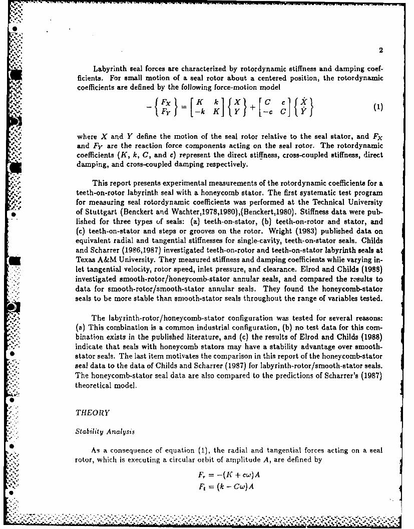
Labyrinth seal forces are characterized by rotordynamic stiffness and damping coef-ficients. For small motion of a seal rotor about a centered position, the rotordynamic
'C coefficients are defined by the following force-motion model
Fy -k .K Y -c)
11 where X and Y define the motion of the seal rotor relative to the seal stator, and Fx
and Fy are the reaction force components acting on the seal rotor. The rotordynamiccoefficients (K, k, C, and c) represent the direct stiffness, cross-coupled stiffness, directdamping, and cross-coupled damping respectively.
This report presents experimental measurements of the rotordynamic coefficients for ateeth-on-rotor labyrinth seal with a honeycomb stator. The first systematic test programfor measuring seal rotordynamic coefficients was performed at the Technical Universityof Stuttgart (Benckert and Wachter,1978,1980),(Benckert,1980). Stiffness data were pub-
- lished for three types of seals: (a) teeth-on-stator, (b) teeth-on-rotor and stator, and(c) teeth-on-stator and steps or grooves on the rotor. Wright (1983) published data onequivalent radial and tangential stiffnesses for single-cavity, teeth-on-stator seals. Childsand Scharrer (1986,1987) investigated teeth-on-rotor and teeth-on-stator labyrinth seals at
- Texas A&M University. They measured stiffness and damping coefficients while varying in-let tangential velocity, rotor speed, inlet pressure, and clearance. Elrod and Childs (1988)
S.: investigated smooth-rotor/honeycomb-stator annular seals, and compared the results todata for smooth-rotor/smooth-stator annular seals. They found the honeycomb-statorseals to be more stable than smooth-stator seals throughout the range of variables tested.
The labyrinth-rotor/honeycomb-stator configuration was tested for several reasons:(a) This combination is a common industrial configuration, (b) no test data for this com-bination exists in the published literature, and (c) the results of Elrod and Childs (1988)indicate that seals with honeycomb stators may have a stability advantage over smooth-
* stator seals. The last item motivates the comparison in this report of the honeycomb-stator- seal data to the data of Childs and Scharrer (1987) for labyrinth-rotor/smooth-stator seals.'" The honeycomb-stator seal data are also compared to the predictions of Scharrer's (1987)
theoretical model.
THEORY
* Stability Analysis
• As a consequence of equation (1), the radial and tangential forces acting on a sealrotor, which is executing a circular orbit of amplitude A, are defined by
F, = -(K + cw)A
Ft r,=(k-Cw)Ao
--*- *-'.

:..
S. 3
where w is the running speed. Thus, K and c produce a radial force on the seal rotor, andk and C produce. a tangential force. The radial force F, in a labyrinth seal is normallysmall compared to other radial fores acting on a rotor; therefore , K and c are of minorconsequence. If positive, the tangential force Ft is destabilizing since it supports the
-" whirling motion of a forward whirling rotor. Both k and C are positive for most practicallabyrinth seal applications; hence, the compelling reason for determining the rotordynamicseal coefficients is to determine the relative values of k and C. The whirl frequency ratio,defined by
f = k/Cw,
is used in this report to compare k and C. Reducing the value of f improves the stabilityof a rotor system.
UScharrer's Analysis
Prediction of the rotordynamic coefficients requires a flow field model to predict the ax-ial and circumferential pressure distribution acting on the seal rotor. Most early attemptsto model the flow field in a labyrinth seal used a single control volume, concentrating on
-; the circumferential flow components. However, the labyrinth seal is known to have twodistinct flow regimes: a jet flow region in the leakage path and a recirculation region in thecavity. Hence, Fujikawa et al. (1984), Wyssmann et al. (1984), and Scharrer (1987) have
- developed two-control-volume analyses to accurately model the known physics of the flow.Scharrer's model is used in this report to generate theoretical predictions for comparison
. to experimental data.
In Scharrer's model, the shear stresses at the rotor and stator surfaces (r. and r) aremodeled using the Blasius formula for turbulent pipe flow
_ 1 '..o (UnDh)rn°
2 .PUn O()
where Urn is the mean flow velocity relative to the surface upon which the shear stress iscting, and Dh is the hydraulic diameter of the particular control volume. No published
data are available for the friction cueflicients, no and mo, for the honeycomb-stator surface. used in the 'ests reported here. The following values were determined empirically from
pressure drop versus flow tests for smooth-rotor/honeycomb-stator seals
ms = -0.1083 ns = 0.2820.
Scharrer uses a perturbation analysis to linearize the governing equations. Expanding'" the governing equations in the perturbation variables yields a system of twelve linear
algebraic equations per cavity. Solution of these equations yields the pressure distributionalong and around the seal. Integration of the pressure distribution leads to the solution
*: for the rotordynamic coefficients.
.........
S. . -° .. :... &ii:~:--&.c..-:&.

-~ , 4
TEST APPARATUS
. The test results reported here were obtained using the Texas A&M Air Seal TestApparatus. The test apparatus will be described here briefly. A detailed description wasprovided by Childs et al. (1986). As illustrated in figure 1, the rotor shaft is suspended,pendulum fashion, from an upper, rigidly-mounted, pivot shaft. This arrangement allowshorizontal (harmonic) motion of the rotor. A cam within the pivot shaft provides vertical(static) positioning of the rotor. The rotor is excited, horizontally, by a hydraulic-shakerhead which acts on the rotor-shaft housing. The design of the test rig, which is furtherillustrated in figure 2, permits the installation of various rotor/stator combinations. Thetest apparatus has been modified since the 1986 reference to-permit an increase in topoperating speeds from 8,000 to 16,000 cpm. Changes include the use of a hydraulicallyfitted rotor, the introduction of high-speed carbon seals, and the replacement of a roller-element thrust bearing with a Torrington, water-lubricated, swing-pad bearing. The statorof figure 2 is supported in the test section housing by three piezo-electric, quartz, load cellsin a triheral configuration. These load cells measure the pressure-induced forces due to
0* "rotor motion within the stator. Accelerometers are provided on the stator to correct foracceleration-induced forces which are measured by the load cell.
TEST PARAMETERS
5 The parameters varied during the tests were supply pressure, rotor speed, circumfer-ential velocity of the inlet air, and seal configuration. Test results for six teeth-on-rotorlabyrinth gas seal configurations are presented. Three of the seals have honeycomb stators,
each with a different rotor-to-stator clearance. The other three seals have smooth stators,each wluh a clearance equal to one of the honeycomb-stator seals. The seals are illustrated
in figure 3. Seals 1, 2, 3, and 4 were tested for this study, and the data for these seals arereported here for the first time. Seals 5 and 6 were tested previously and documented byChilds and Scharrer (1987). The data are presented here again to provide comparison tothe corresponding honeycomb stator seals (seals 2 and 3).
. The test points for the other three variables are shown in table 1. The inlet airpressure and attendant mass flow rate through the seal are controlled with a flow controlvalve located upstream of the seal. Rotor speed is controlled by a variable speed electricmotor with a frequency controller. The inlet circumferential velocities are controlled using
the inlet guide vanes shown in figure 4. The guide vanes are contained in sleeves and located- immediately upstream of the test seal. The no-prerotation case is obtained without guide
vanes. High and low prerotation velocities are obtained for the different, guide-vane-depthsA of figure 4. The inlet circumferential velocity is calculated from measured values for thevolumetric flow rate, upstream temperature and pressure, and a flow-turning correctionin accordance with Cohen et al. (1972). The circumferential velocity can not be variedarbitrarily, because it depends on the supply pressure and the flow resistance of the sealbeing tested. The inlet circumferential velocity set points for each seal are shown in table2. Inlet circumferential velocity varies a maximum of - 10% with supply pressure and
re oreA

rotor speed from the values in table 2. When reviewing the following test results, figure3, table 1, and table 2 should be consulted for the definitions of symbols used. Also, note
that circumferential velocity ratio is used to represent inlet circumferential velocity; this
is the ratio of inlet circumferential velocity to rotor surface speed.
As noted in table 2, the inlet circumferential velocity test point varies significantly
when seal clearance is varied. Therefore, the rotordynamic coefficients cannot be plottedversus clearance because the variation in inlet circumferential velocity with clearance would
affect the results. The effect of clearance is displayed by plotting the coefficients versusinlet circumferential velocity for each seal on the same plot. This procedure allows onlyone rotor speed and one supply pressure per plot.
The uncertainty of the rotordynamic coefficients was calculated using the methoddescribed by Holman (1978). For the seal configurations tested, the maximum uncertainties
in the stiffness and damping coefficients were 15 N/mm (86 lb/in) and 32 N-s/m (0.18 Ib-s/in), respectively. The uncertainty in the cross-coupled damping coefficients are of thesame order of magnitude as the coefficients themselves; therefore, cross-coupled dampingdata are not presented here.
TEST RESULTS
Honeycomb-stator seal data are compared to smooth-stator seal data in figures 5-12.In these figures, solid lines represent the hone ycomb-stator test results and broken linesrepresent the smooth-stator test results. The smallest clearance seals (seals 1 & 4) and thehighest inlet circumferential velocity (swirl 3) are used for plots in which these parameters
*,are not varied. Further data are presented by Hawkins (1988).
Leakage
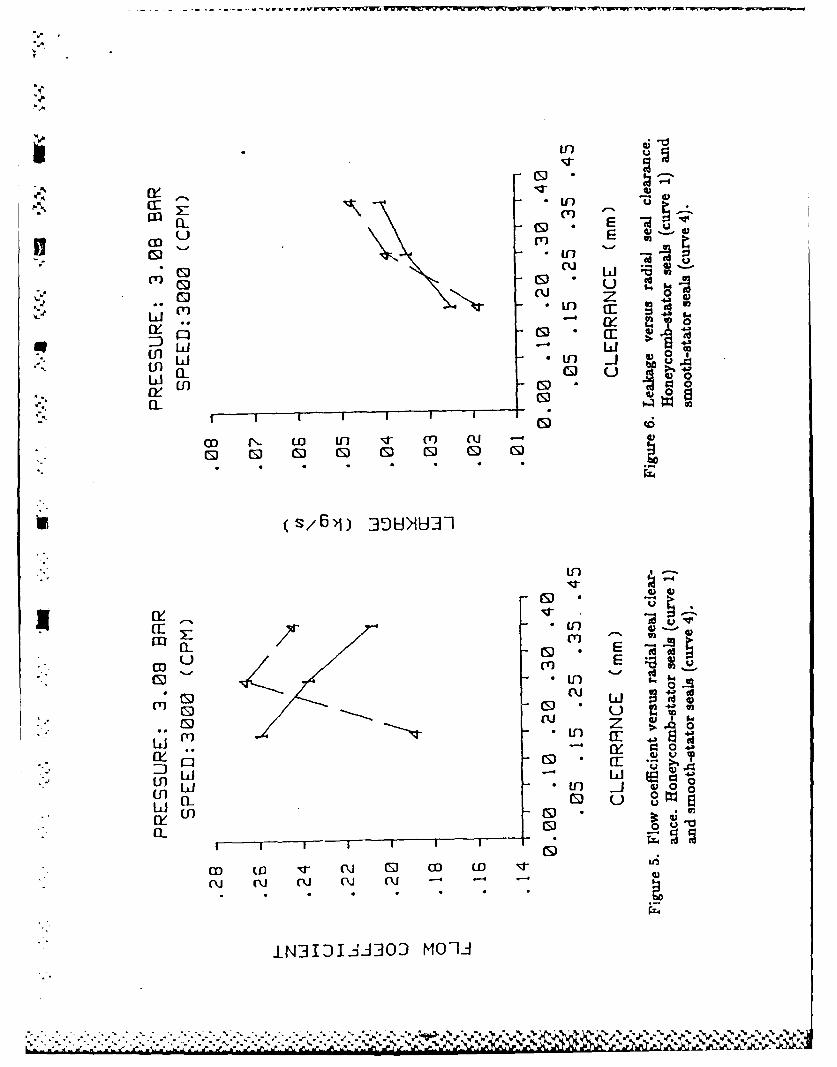
Leakage is represented by the flow coefficient,
'. ~rh V-
7rDCrP"
" Figure 5 is a plot of flow coefficient versus seal clearance for an inlet pressure of 3.08 bar
and a rotor speed of 3000 cpm. Curve 1 represents the honeycomb-stator seals and curve 4represents the smooth stator seals. Leakage did not vary with inlet circumferential velocity,thus the data presented are for inlet circumferential velocity 3 only. Examination of thefigure reveals that the honeycomb-stator seal leaks more at the smallest clearance andthe smooth-stator seal leaks more at the largest clearance. This result is consistent withStocker et al. (1977). One would expect the honeycomb-stator seal to leak less than thesmooth-stator seal because its greater roughness increases the flow resistance. However,
in the honeycomb-stator seal, part of the leakage air may bypass the apparent flow pathby passing into and out of honeycomb cells. Thus, relative to the smooth-stator seal, the
honeycomb-stator seal has a larger effective leakage area for a given clearance. When the

"'. ..4 -,. 6
clearance is small, the increased leakage area results in greater leakage in the honeycomb-
stator seal versusthe smooth-stator seal.
Figure 6 is similar to figure 5, except that leakage is represented by the dimensionalmass flow rate. This figure shows that leakage increases as clearance increases.
Direct Stiffness
Direct stiffness is plotted versus rotor speed for various pressures in figure 7. Again,the solid lines are for the smallest clearance honeycomb-stator seal, and the broken linesare for the smallest clearance smooth-stator seal. Direct stiffness of the honeycomb-statorseal is negative and becomes more negative as rotor speed increases. The smooth-statorseal has a similar characteristic, but has a larger direct stiffness magnitude. Direct stiffnessbecomes more negative as pressure increases for both stator surfaces.
Cross-Coupled Stiffness
Cross-coupled stiffness is plotted versus rotor speed for various pressures in figure 8.Cross-coupled stiffness increases with rotor speed for both seals. For the honeycomb-stator
seal, cross-coupled stiffness is negative at low speed and increases to about 300 N/mm at
the highest rotor speed. For the smooth stator seal, cross-coupled stiffness has a smallpositive value at low rotor speeds, increasing to about 350 N/mm at the highest rotorspeed. Due to the results of Elrod and Childs (1988), cross-coupled stiffness was expected
-.'.'. to be less positive for the honeycomb-stator seal compared to the smooth-stator seal for all
rotor speeds. The data show that the cross-coupled stiffness of the two seals have similar
magnitudes at high rotor speeds. This plot also shows that increasing pressure increasesS..the absolute value of cross-coupled stiffness.
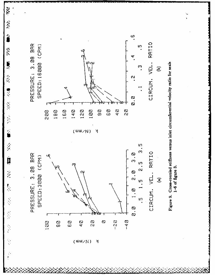
Figure 9 illustrates cross-coupled stiffness versus circumferential velocity for the threehoneycomb-stator seals (1, 2, 3) and the three smooth-stator seals (4, 5, 6). Figure 9(a)
is for an inlet pressure of 3.08 bar and rotor speed of 3000 cpm, and figure 9(b) is forthe same pressure and rotor speed of 16,000 cpm. Figure 9(a) shows that cross-coupledstiffness increases roughly linearly as inlet circumferential ratio increases for both statorsurfaces. The increase is greater with the smooth-stator seal. In figure 9(b), cross-coupledstiffness increases significantly from zero inlet circumferential velocity to the first positive
* value of inlet velocity; however, from the first positive inlet velocity to the second positiveinlet velocity, the cross-coupled stiffness increases only slightly or in some cases decreases.This trend is present for both stator surfaces. Returning to figure 9(a), for the honeycomb-
stator seal, cross-coupled stiffness is much lower in the small clearance seal (seal 1) thanin the larger clearance seals (seals 2 & 3). Increasing seal clearance has little effect on the
* cross-coupled stiffness of the smooth-stator seal. At the higher rotor speed (figure 9(b)),-' seal clearance has little effect on cross-coupled stiffness in the honeycomb-stator seal. The
small clearance smooth-stator seal (seal 4) has a much higher cross-coupled stiffness than
0
•-p **• ** 45..
the larger clearance seals (seals 5 & 6). Note that cross-coupled stiffness of the largerclearance smooth-stator seals does not depend on rotor speed.
Direct Damping
Direct damping is plotted versus rotor speed for various pressures in figure 10. Directdamping has essentially the same magnitude for either stator surface. However, damp-ing for the honeycomb-stator seal first increases and then decreases with increasing rotorspeed, while damping in the smooth-stator seal does not depend on rotor speed. Also,damping increases with pressure for both stator surfaces, but the increase is greater in thehoneycomb-stator seal.
Figure 11 is a plot of direct damping versus inlet circumferential velocity ratio for eachseal conliguration. Damping does not have a clear dependence on inlet circumferentialvelocity in the honeycomb-stator seals, but increases with increasing inlet circumferentialvelocity in the smooth-stator seals. Damping increases somewhat from seal 1 (the smallestclearance seal) to seal 2. However, damping in seal 2 and seal 3 is roughly the same. Inthe smooth-stator seal, damping first falls and then rises as clearance increases. This plotis for pressure of 3.08 bar and rotor speed of 3000 cpm. The same trends are repeated atother inlet pressures and rotor speeds.
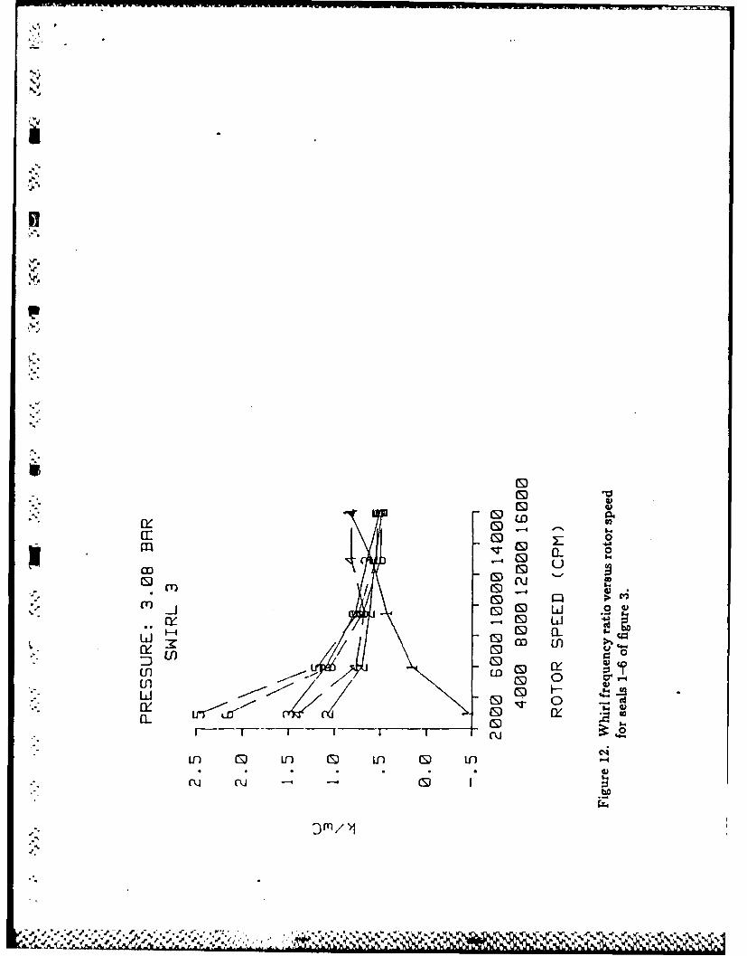
Whirl Frequency Ratio
Figure 12 is a plot of whirl frequency ratio versus rotor speed for the three honeycomb-stator seals and the three smooth-stator seals. As noted previously, lower values of whirlfrequency ratio indicate a more stable seal. Note that at the lower rotor speeds, eachhoneycomb-stator seal is more stable than the comparable smooth-stator seal, and thatfor a particular stator surface, the small clearance seals are more stable than the largerclearance seals. At the higher rotor speeds, stator surface does not significantly affectstability. Also, the small clearance seals (seals 1 & 4) are less stable than the others at thehigher speeds.
COMPARISON TO THEORY
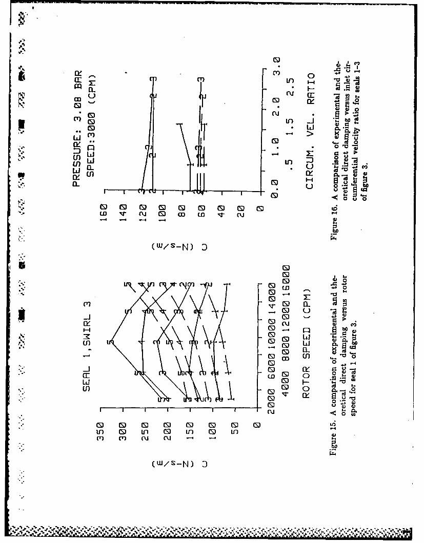
Data for the honeycomb-stator seals are compared to the predictions of Scharrer'smodel in figures 13-16. The experimental data are represented by solid lines and theoreticalpredictions are represented by broken lines in each figure.
Cross-Coupled Stiffness
Figure 13 is a plot of cross-coupled stiffness versus rotor speed for various pressures• .for the smallest clearance seal. The theory correctly predicts that cross-coupled stiffness*rises as rotor speed rises. The theory does not predict the negative values found at low
'p'

8
rotor speeds. In general, the model predicts positive values of cross-coupled stiffness cor-rectly within 25%. Figure 14 is a plot of crt-.s-coupl.d stiffness versus inlet circumferentialvelocity ratio for the three honeycomb-stator seals. The model predicts a larger rise incross-coupled stiffness with increasing circumferential velocity than is shown in the ex-
* perimental data. The model also predicts little increase in cross-coupled stiffness withincreasing clearance.
.Direct Damping
Direct damping is plotted versus rotor speed for various pressures in figure 15. Themodel predicts that damping increases with increasing rotor speed, whereas the data showthat damping first increases and then decreases with increasing rotor speed. The modelconsistently underpredicts the magnitude of the damping at low rotor speeds, and is accu-rate at high rotor speeds. However, at the highest rotor speeds tested, the model predic-tions and the test results are diverging. Figure 16 is a plot of direct damping versus inletcircumferential velocity ratio for the three honeycomb-stator seals. The model correctlypredicts that damping does not depend on inlet circumferential velocity ratio. The modelalso predicts that damping does not increase significantly as clearance increases. This istrue only at the larger clearances.
• . CONCLUSIONS
The test data support the following conclusions for the labyrinth-rotor/honeycomb-
stator seals:
1) Cross-coupled stiffness is generally positive. Cross-coupled stiffness increases withrotor speed and with inlet circumferential velocity. At the lower rotor speeds, cross-
-'- coupled stiffness is much lower for the smallest clearance seal than for the other two
seals. At the higher rotor speeds, cross-coupled stiffness is approximately the samevalue regardless of clearance.
2) Direct damping is positive, and is much lower in the smallest clearance seal than inthe two larger clearance seals.
",p.-
By comparing the results for the honeycomb-stator and smooth-stator seals, the fol-* *lowing conclusions may be drawn:
1) The honeycomb-stator seals leak more than the smooth-stator seals when the clearanceis small. The honeycomb-stator seals leak less when the clearance is large.
" 2) The honeycomb-stator seal is more stable at low rotor speeds. For high rotor speedsstator surface does not affect stability.

.
By comparison of experimental results and theoretical predictions for honeycomb-.stator seals, the following conclusions may be drawn:
1) The model does not predict the negative values measured for cross-coupled stiffnessat low rotor speeds.
2) The model consistently predicts the positive values of cross-coupled stiffness of theii honeycomb-stator seal correctly within 25% of the measured values. The model cor-rectly predicts the weak dependence of cross-coupled stiffness on clearance for thelarger clearances.
3) The model incorrectly predicts that direct damping increases with speed, and doesnot predict the decrease in damping at small clearance. For the two larger clearanceseals the model produces good results for tested rotor speeds above 12,000 cpm. Below12,000 cpm, the model underpredicts direct damping by 50%.
In general, Scharrer's model gives useful results for cross-coupled stiffness in thelabyrinth-rotor/honeycomb-stator seal for the range of variables tested. Scharrer's modelcan give useful results for direct damping in the labyrinth-rotor/honeycomb-stator seal byapplying a rotor-speed correction factor to the predicted damping. Overall, the modelproduces better results for the larger clearances. The increased significance of unmodeledeffects at smaller clearances - such as the unmodeled leakage path through the honey-comb cells - is probably responsible for the reduced performance of the model at smallerclearances.
Values of the rotordynamic coefficients for the two larger clearance seals tend to bemuch closer together than to the smaller clearance seal. This is true for both the labyrinth-rotor/honeycomb-stator seal and for the previously untested smallest clearance labyrinth-rotor/smooth-stator seal. Since there are many practical applications where labyrinth sealsare used with clearances below the tested range, further testing with smaller clearancesare required.
b.
j-I
W. bJ. W ~j

10
REFERENCES
Benckert, H., and Wachter, J., 1978, "Querkrafte aus Spaltdichtungen-Eine moglicheUrsache fur die Laufunruhe von Turbomaschinen," Atomkernenergie, "32, Lfg. 4, pp. 239-246.
Benckert, H., 1980, "Stromungsbedinte Federkennwerte in Labyrinthdichtungen,"Doctoral dissertation at University of Stuttgart.
. Benckert, H., and Wachter, J., 1980, "Flow Induced Spring Coefficients of LabyrinthSeals for Applications in Rotordynamics,," NASA CP 2133, Proceedings from a workshopon Rotordynamic Instability Problems in High-Performance Turbomachinery-1980, heldat Texas A&M University, College Station, TX, pp. 189-212.
Childs, D. and Scharrer, J., 1986, "Experimental Rotordynamic Coefficient Results forS.. Teeth-On-Rotor and Teeth-On-Stator Labyrinth Gas Seals," ASME Paper No. 86-GT-12,
Also accepted for ASME Journal of Engineering for Gas Turbines and Power.
Childs, D., and Scharrer, J., 1987, "Theory Versus Experiment for the RotordynamicCoefficients of Labyrinth Gas Seals: Part II - A Comparison to Experiment," RotatingMachinery Dynamics, Vol. 2, proceedings from the ASME Conference on MechanicalVibration and Noise, Boston, MA, pp. 427-434.
Childs, D., Nelson, C., Nicks, C., Scharrer, J., Elrod, D., Hale, K., 1986, "TheoryVersus Experiment for the Rotordynamic Coefficients of Annular Gas Seals: Part 1, TestFacility and Apparatus," ASME Trans. J. of TRibology, Vol. 108, pp. 426-432.
Cohen, H., Rogers, C., and Saravanamutto, H., 1972, Gas Turbine Theory, LongmanGroup Limited.
Ehrich, F., and Childs, D., 1984, "Self-Excited Vibration in High-Performance Tur-Sbomachinery," Mechanical Engineering, May, pp.66-78.
Elrod, D., and Childs, D., 1988, "Experimental Rotordynamic Coefficient Results forHoneycomb Seals", Texas A&M Turbomachinery Laboratory Report TRC-Seal-1-88.
Fujikawa, T., Kameoka, T., and Abe, T., 1984, "A Theoretical Approach to LabyrinthSeal Forces," NASA CP 2338, Proceedings from a workshop on Rotordynamic InstabilityProblems in High-Performance Turbomachinery-1984, held at Texas A&M University,College Station, TX, pp. 173-186.
Hawkins, L., 1988, "A Comparison of Experimental and Theoretical Results forLabyrinth Gas Seals," Masters Thesis, Texas A&M University, College Station, TX.
02:
. .
"" 11
Holman, J., 1978,Ezperimental Methods for Engineers, McGraw-Hill, New York, pp.i' " 45.
Scharrer, J., 1987, "Theory Versus Experiment for the Rotordynamic Coefficientsof Labyrinth Gas Seals: Part I - A Two Control Volume Model," Rotating MachineryDynamics, Vol. 2, proceedings from the ASME Conference on Mechanical Vibration andNoise, Boston, MA, pp. 411-426.
Stocker, H., Cox, D., and Holle, G., 1977, "Aerodynamic Performance of Conventionaland Advanced Design Labyrinth Seals with Solid-Smooth, Abradable, and HoneycombLands," NASA CR-135307, pp. 63-72.
Wright, D., 1983, "Labyrinth Seal Forces on a Whirling Rotor," Rotor DynamicalInstability, ASME, New York, pp. 19-31.
Wyssmann, H., Jenny, R., and Pham, T., 1984, "Prediction of Stiffness and Damping
Coefficients for Centrifugal Compressor Labyrinth Seals," ASME 84-GT-86. Presented atthe 29th International Gas Turbine Conference and Exhibit, Amsterdam, The Netherlands.
a °
-

12
NOMENCLATURE
C, c Direct and cross-coupled damping coefficients (Ft/L)
Cr Radial clearance (L)D Rotor diameter (L)F Seal reaction-force magnitude (F) "K, k Direct and cross-coupled stiffness coefficients (FIL)f Whirl frequency ratioTh Leakage mass flow rate (MILt)"ms, ns Friction coefficientsP Fluid pressure (F/L 2 )R Gas constant for air (L 2 /Tt 2 )T Fluid temperature (T)X, Y Rotor-to-stator relative displacement components (L)V Kinematic viscosity (L 2 /t)
p Density of fluid (M/L2 )w Shaft angular velocity (l/t)
Subscripts
r Reservoir value, radial componentSSump valuet Tangential component
%-
p.-.
* V.
# 5 -
* ' -

Table 1. Definition of symbols used in figures.
Supply Pressure Rotor Speeds Inlet Circumferential Velocities
1 - 3.03 bar 1 - 3,000 cpm 1 - Zero circumferential velocityS 2 - 4.46 bar 2 - 6,000 cpm 2 - Low velocity with rotation
3 - 5.84 bar 3 - 9,500 cpm 3 - High velocity with rotation4 - 7.22 bar 4 -13,000 cpm5- 8.25 bar 5- 16,000 cpm
Table 2. Inlet circumferential velocity set points.
Seal Circumferential Velocity (m/s)Swirl I Swirl 2 Swirl 3
1 0.0 14.9 38.72 0.0 20.9 56.33 0.0 24.6 64.14 0.0 10.3 28.15 0.0 22.8 59.96 0.0 28.7 76.3
.A -

S.
.. 4.
%
%P A PIVOT SHAFT
f'lr HRUST SEARING
JNLOAD CE.LL
%' TEST ROTOR ,
• , SE[AlL ROTOR"
.%', /SEAL STATOR
Figure 1. Test apparatus.
Hydraulically Fitted
High Speed Test Rotor,...,'Carbon Seals
/ Hollow-, Roller
O Ine"'"or " " "stator ,
Swn Port
Thrust Bearing",
.,
.. Figure 2. Cross-sectional view of test section.
,

coo
Z'-4 CI2.000
UU
CI 0
-4- -4-
4-,4
o"-4
* U! -~El
0V
Cd
t3
U), A1 -A

0%
,x
VA
WosIn 016 n
s.- -
0..19 cm0.Z
6.0 0.1cm .3$*~~~~( I0Z/ 8J 0.12)
Fiur 4. Ine-guide-vane detail.
-.............. e 4. Inlet
tn
m EDC" 0 u u
ini
-40
w In
/L CD
IL*I
CS/61 39Lii I
a_ C
tnn~tn 0 J )0
urn0 0
(y a
3n -1 0
1N3131 3JO MOIJ
.N.N N6

Noww
mr 0
I-40 W
(S) w
U] 0
ad
0 Qf 0 CDf CD Gf 0 D0 DQ
(WLt)4 M ?I
0.2
U U1 1 0
0~U ..
II, CD w11/ 0 W
(1V411
r~-r v~F~CD
(.D
0CYU)
0l w L)e '
LLI 4L
*-I m--- I i k
-4 -
ly 0
am a-
0 m G ) >-( J D Cn' - .4 d - -
M w4
w 0-
(WW/N)*>
%V

S II)
CE * C
Ju- a- 0T
(T) JO
L5j
5..' Cj)f V
IL C1) Ri -Z 0 n
(W/S-N) 3
ou 0
L1n mS W .
V7V (S o ci.-J S)
_i D 0
4-l CEUED
CS) C CS) C CD C If
(W/s-N) 3
N0N
CE 0L
0-Q u3
o 0 cj 6..
9CD a- $ 9
h /O 0
0
cLlIn 0D U- 0 in 0 in
D Vn
(\J (J -4 - AL

00
CS) 6. 5lCS). w
W~ T >
in 0U) .uc
00
I I I 1 4
(WW/N) A1
U QJ
W-X. ELD
1S 1 64-
U)) 0.
- ED . ,w CL 0
Cou
(S] CD-~-
(ww/N) "
0 SI)
t0ItiJ 4)
wcrj
a. 0o .-
0 00 00 0
CW/SN 9-
ED 0w >
00D0 0 44
w a_ 0 a. :6 c
VS 1H00- u 0
u0 Ia. .
0 0-
I ) G D () C) () CS) Q CE CED v ru CS co LO v-
m- -m --4 Cu -
(w/s-N) 9

THEORY VERSUS EXPERIMENT FOR THEROTORDYNA IC COEFFICIENTS OF LABYRINTH GAS SEALS:
PART I - A TWO CONTROL VOLUME MODEL'
JosEf, K. SCHANtER3MECHANICAL ENGINEERING DEPARTMENT
TEXAS A&M UNmivsrrYCOLLEGE STATION, TEXAS 77843
SUMWARYThe basic equations are derived for a two-control-volume model for compreusible flow in a labyrinth seal. Therecirculation velocity in the cavity is incorporated into the model for the st time. The tow is assumed tobe completely turbulent and isoenergetic. The wall friction factors are determined. using the Blasius formula.Jet Row theory s used for the calculation of the recirculation velocity in the cavity. Linearised seroth and
C first-order perturbation equations are developed for small motion about a centered position by an expansionin the eccentricity ratio. The seroth-order presure distribution is found by satisfying the leakage equationwhile the circumferential velocity distribution is determined by satisfying the momentum equations. Thefirst-order equations are solved by a separation of variable solution. Integation of the resultant pressuredistribution along and around the seal defines the reaction force developed by the seal and the correspondingdynamic coefficients.
g NLTRODUCTIONThe problems of instability and synchronous response in turbomachines have arisen recently because ofthe trends in design toward greater efficiency with higher performance. To achieve these design goals, the
. machines are designed for higher speeds, larger loadings, and tighter clearances. As loading are increasedand clearances decreased, Ruid forces increase and can lead to unstable or self-excited vibrations. One ofthe rotordynamic force mechanisms which has been shown to cause self-excited vibration and synchronousresponse in centrifugal compressors is that of the forces developed by labyrinth seals.
The low in a labyrinth seal has been shown by experiment 1ll and calculation (2,3,41 to be comprised of twoflow regimes: a jet flow region in the leakage path and a recirculating velocity region in the cavity itself (seefigure 1). The first attempts at analysis of this system neglected the axial velocity components in the flow
- and concentrated on the circumferential components. This was the single-control-volume approach, used inrefs 15,S]. In an attempt to improve upon the results of these analyses, the two-control-volume approachwas introduced. The most notable of the two-contrl-volume analyses is that of Jenny et al. 171. Jenny et&L. 17] used the two-control-volume approach in conjunction with a 2-D CFD solution to the Navier-Stokesequations to account for the free shear stress between the jet fow and the cavity fow. However, theyneglected the reaculating velocity in the cavity and assumed the flow to be incompressible. Further, the
.. present author obtains different signs in the expansion of the continuity equation and different perturbationequations. Theme discrepancies are explained in detail in Appendix D. The theory of Jenny et al 17) showedsubstantial improwement in the prediction of stiffness and damping coefficients, but in the end, correctionfactors had to be incorporated into the calculation of the shear strew to improve the correlation with testdata.
This paper introduces the cakulation of the recirculation velocity into the analysis. The model for therecirculation velocity, U2, used here is illustrated in figure 2. This velocity component is important in thecalculation of the cavity shear stresses. The focus is on the shear streses, because experimental result 18)have shown that the stiffness and damping coefficients are very sensitive to the circumferential velocity in theseal. In the control volume analysis to be presented, the solution to the circumnferential momentum equation
'This work was supported in part by NASA Grant NAS3-181 from NASA Lewis Research Center (TechnicalMonitor, Robert Hendricks) and AFOSR Contract F49820-82-K-0035 (Technical Monitor, Tony Amos)
0

,0
yields the circumferential velocity in the seal. An improvement in the shear stress calculation will yield animprovement in the calculation of the stiffness and damping coefficients. The CFD result, of Rhode 12,31 areused to evaluate the mqdel - for shear stress and recirculation velocity used in this paper. The results of thisanalysis are compared to a new set of experimental results for teeth-on-rotor and teeth-on-stator labyrinthseals in Part 2 of this paper.
% CONTROL VOLUME MODELLINGN Before proceeding with the solution development, the approach taken in modelling the flow will be discussed.
As mentioned previously, the flow in a labyrinth seal is known to have two distinct regions: a jet flow region*in the leakage path and a recirculating flow region in the cavity itself (see figure 1). Therefore, a two-control-
volume model seems appropriate. The choice of control volumes is between the *box-in-@,bx model (seefigure 3) of Jenny et al. 17) or a more conventional model with a control volume for the jet flow and onefor the recirculating flow in the cavity, as shown in figure 2. The two-separate-control-volume model waschosen since it is suggested by the known physics of the flow. The flow enters the seal and separates intotwo distinct flow regions which are separated by the dividing streamline.
The final question is whether the control volumes should be defined using a geometric boundary or usingthe dividing streamline as the boundary. The dividing streamline approach seems, at first, to be the obviouschoice. The governing equations would be simplified by the restriction of no flow acro a streamline, thefree shear stres relations are derived for flow along the dividing streamline, and the solution for the velocityof the recirculating flow may be derived for flow along the dividing streamline. Despite these advantages, the
* dividing streamline approach was not used, due to mathematical constraints. The mathematical limitationsof the dividing streamline approach are dealt with in detail by Scharrer 19). The geometric boundary approachrelies on the amumption that the dividing streamline makes a small angle with the horisontal. As will beshown, this is a good assumption which laas been verified experimentally. The geometric boundary approachand solution is provided in the following section.
GEOMETRIC BOUNDARY APPROACHAssumptions
(1) The fluid is considered to be an ideal gas.(2) Pressure variations within a chamber are small compared to the pressure differences across a seal
strip.(3) The lowest frequency of acoustic resonance in the cavity is much higher that that of the rotor speed.(4) The eccentricity of the rotor is small compared to the radial seal clearance.(5) Although the shear stress is sig.ificant in the determination of the flow parameters (velocity etc. ),
the contribution of the shear stress to the forces on the rotor are negligible when compared to the pressureforces.
Zf. (6) The cavity flow is turbulent and isoenergetic.(7) The recirculation velocity, U2, is unchanged as it swirls within a cavity.
"; ProcedureThe analysis presented here is developed for the teeth-on-rotor 'see-through' labyrinth seal shown in figure 5.The equivalent equations for the teeth-on-stator labyrinth seal are given in Appendix A. The continuity andcircumferential momentum equations will be derived for the two-control-volume model shown in figures 2,6,7
and 8. A leakage model will be employed to account for the axial flow. The governing equations are liearied* using a perturbation analysis for small motion about a centered position. The seroth-order continuity and
momentum equations will be solved to determine the steady state pressure, axial and circumferential velocity*. for each cavity. The first-order continuity and momentum equations will be reduced to linearly independent,
algebraic equations by assuming an elliptical orbit for the shaft and a corresponding harmonic response forthe pressure and velocity perturbations. The force coefficients for the seal are found by integration of thefirst-order pressure perturbation along and around the shaft.
GOVERNING EQUATIONSContinuity EquationThe control volumes of figures 2 and 6 have a unity circumferential width. Their continuity equations are:
0 :;. i. i.iii.. ?( . ?4;;. i . ° ;. .,. .q%..-....'

ajpA, aoW, A I++ 0at Reiae +
8pA2 _ pW2A2at+ R, :o(2)For the teeth-on-rotor case, Al =LCr, A2 = LB, Raj = Re, and R82 = Rs + B.
Momentum EquationsThe following momentum equations for control volumes I and II are derived using figures 7 and 8 whichshow the pressure forces and shear stresses acting on the control volumes.
apWA+ 2pW 1A1 8W -pW LAI + WA 1 Op + rn4Wi
at Re at Rol O Rol 88
k+ I .W1 - = a s +r,Li- w. aL (3)
OpW 2A2 2pW 2A2 OW2 pW2 GA2 W2A2Bp.'W2 + +W IA + WAa
at ReZ2 0 Rs2 a9 R 2 a9
+ A2 LA _e l-. + r, anri (4)where ar and as are the dimensionless length upon which the shear stresses act and are defined for the
teeth-on-rotor labyrinth by
a., = a, = (2 + Lq)IL. (5)
W. is the circumferential velocity between the control volumes.
Blauius 110] determined that the shear stresses for turbulent low in a smooth pipe could be written as
12 VUD
where U. in the mean Bow velocity relative to the surface upon which the shear stress i acting. The constantsmo and no can be empirically determined for a given surface from pressure Low experiments. However, forsmooth surfaces the coefficients given by Yamada fll for turbulent Low between annular surfaces are:
13 0= -0.25 fto = 0.079
' Applying Blasius' equation to the labyrinth rotor surfaces Yields the following definitions for the rotor shearstress in the circumferential direction. Note that the recirculation velocity, U2 , is included in the definitionof the total velocity acting on the rotor.
-T) +U (RS2 W~- W 2 )nr (VR 2 W~-W 2 T2) -fD~ M+ (6)
where Dh2i is the hydraulic disinter of control volume II, defined by
A; = 2B L1/(B, + Li) (7)
Similarly, the stator shear stree in the circumferential direction is:
1 I - ~ r (v ? UDhli).= ~ W +UW e, ()T o W i n s o , ( 8 )
. - . - .- , - - . - . , , '., . . .. - . . ... . . . . . , ,

5 rlw rl rr ruw a ' .-. m
where Dhl. is the hydraulic diameter of control volume I, defined by
DI, = 2CrL/(Cr, + L,) (9)
and the axial velocity, UI1, is
U1 = ,+,/PCr, (10)
Figure 9 shows a comparison of the predictions from equation (8) and CFD results for stator wall shear stressk for seal A of table 1. The figure shows that the comparison is very good. Similar results are obtained for theother seals of table 1. Figure 10 shows a comparison of rotor wall-shear-stress predictions from equation (6),CFD and averaged CFD for seal A of table 1. The averaged CFD results is used here for comparison sincethe bulk flow model yields a single averaged result for cavity shear stress and is not capable of modellingthe complex flowfield.The figure shows that the prediction of equation (6) is close to the CFD results.Thedips in the CFD results are the lower corners of the cavity. Similar results are obtained for the other sealsof table 1.
Table 1. Seal geometries calculated by Rhode.
Seal
A B C DRe 72.5043mm 72.5043mm 72.5043mm 41.780mmB 3.175mm 3.175mm 3.175mm 0.889mmL 3.175mm 3.175mm 3.969mm 0.8585mmTp 0.35mm 0.35mm 0.35mm 0.15mmCr 0.4064mm 0.508mm 0.508rmm 0.2159mm
The flow across a labyrinth tooth is very similar to the flow of a turbulent jet issuing from a slot. The problemwith using jet-flow results for labyrinth seas is that current jet-flow theory only considers the flow of ajet witha coflowing stream or a crosaflowing stream, not both. In the following derivation, the relationships given byAbramovich 1121 for the velocity profile of a semi-contained, one-dimensional, turbulent jet with a coflowingstream are assumed to apply for the two-dimensional labyrinth seal flow. According to Abramovich 1121, thevelocity profile for such a flow can be shown to fit the following function when compared to experimentalresults:
"= ", + (V2 -l (1).
where the coordinate y, the mixing thickness b, and the boundary layer thickness y are defined in figure11. The relationship between the boundary layer thickness and the mixing thickness was found [12] by
.comparison to experiment to be:
y/b = 0.584 - 0.134(v2/vi) (12)
Once the velocity ratio across the dividing streamline, t2/v1 , is found, equation (12) reduces to a constant.
The total free shear stress is found using Prandtl's mixing length hypothesis [131:
~V If \ (13)fit 1.i~where the mixing length, 1, for a labyrinth seal, has been determined from the calculations of Rhode 12,3] tobe:
t 0.275b (14)
Table 1 shows the seal geometries calculated by Rhode 12,3]. The mixing length, t, given in equation (14)ias the most sensitive factor in this solution. The large magnitude of the mixing length shows the high
=% %
0::::- -""" -- ".:"-::""""--:""": :'" "":::: ":
:--."- - ,.--./-:.:,- ,-,, ..- .-. .-. -.. ".-.- "" ,.-,-.:- ' . ,-- - :5- "" -

.1
turbulence level of the labyrinth flow as compared to similar flows. The typical values given for the mixinglengths of rectangular and round jet tows, in one dimension, are in the range of 0.07 to 0.09. Without theCFD results, one of these values would have to be used and the results of using I/b in the range 10.07,0.091would have been disappointing.
Jenny at al. 171 used a 2-D CFD code to obtain a correlation for lb as a function of clearance and tooth" geometry. Their relation is shown below for the teeth-on-rotor case:
l= 0.055(l + 1.osCrIL + .08 /i;T* ) (15)
However, their shear strew relation neglected the recirculating velocity component, U2 . Upon comparisonwith the data of Rhode 12,31, the mixing length ratio, 1/b, was found to be relatively constant when theshear stress in calculated using all velocity components.
Substituting the differentiated version of equation (11) and equation (14) into equation (13) yields an ex-pression for the total free shear stress. At the interface of the two control volumes (y--O), the total free shearstress is:
fi .68PI(t2- -V']) I (
The circumferential component of the free shear stress is:
+-. 1.6 2
,, = -068pP7(W - WI)+ (U2 - U()2 (W 2 - WI) - (17)
The circumferential component of velocity at the interface, W,,, is obtained from equation (11).
Ki W +. (W2 -W'I) 1[.-2,'1Equations (16,17,18) are all valid along the dividing streamline. Since the control volumes are definedgeometrically and not by the dividing streamline, the shear stress calculated using the above equations isassumed to be close to that existing along the geometric boundary line. This is a good assumption consideringthat the angle of the dividing streamline from the horisontal has been found experimentally to be on theorder of 6 degrees by several investigators 114,15].
The analysis to this point is incomplete in that the recirculation velocity, U2 , and the relationship betweenthe mixing thickness and the boundary layer thickness, y2/6, are undefined. The following section presentsthe jet low theory used to determine the recirculation velocity, U2, and subsequently ht/b. The discussionis rather lengthy, but the final result is relatively simple.
Determi"atio of the recirculaion selociAs mentioned previously, there is no closed-form solution for the fowfield present in a labyrinth seal cavity.The low is highly three dimensional and completely turbulent. An approximation for the velocity profilecan be obtained using the theory for the low of a two-dimensional, turbulent, isoenergetic, half-infinite jet.Figure 12 shows the model for this theory. The low is assumed to enter with one velocity component, in thex-direction, and spread into the cavity developing a y-component of velocity. The model doe4 not accountfor the circumferential velocity component which, is the same order of magnitude as the axial velocity, in alabyrinth seal towfield. The solution procedure involves solving the infinitewsimal form of the x-momentumequation for the dimensionless velocity profile and then solving the integral form of the continuity andmomentum equations in order to determine the dimensionless velocity along the dividing streamline.The following is a summary of the derivation of the equations necessary to determine the dimensionlessvelocity along the dividing streamline. A complete discussion of thi theory can be found in Korst et al. 1161and Scharrer (9]. The following derivation uses the assumption that the curvature in the dividing streamlineis small. The inhmitesinal form of the x-momentum equation which has been reduced using the continuityequation is:
V m m % %

3%2
au au a (8pu\JO- (Z + I y F 78:" ''a +ea= a =o (19)
where e is the apparent (turbulent) kinematic viscosity and the x and y velocity components, u and v,respectively, are time averaged. Since the Row illustrated in figure 12 is a quasi-one-dimensional jet flowwhere there is little or no initial vertical velocity component, equation (19) can be linearized using a smallperturbation method. The following simplified equation of motion is obtained:
,..au, a2,,Nus- "'"a 2 (20)
-'. Here the turbulent viscosity is expressed in a modified form of Prandtl's exchange coefficient, c, so that afterintroducing the dimensionless variables
U I-+-U11
U. U,.
(21)
where f (0)-1.0 as 0 0
and by the transformation
= o 2a 2
the following formulation of the equation of motion is obtained
ao a20 (22)
with the initial conditions
0 = 0,C)= 0for -oo<C<O= 0=for O<<1.0
. '- . 0 ,---for .O <C<
and boundary conditions
* *#=O(C-oo)=0 for f<O
0=(f'oo)=1.0 for f>0Here S is the initial boundary layer thickness shown in figure 12. a is the jet spreading parameter which hasbeen found experimentally by Kort and Tripp 117] to fit the following equation:
* u =12.0 + 2.758M. for air (23)
The solution to equation (22) for the above initial and boundary conditions is:
. 0.51= - erf N , - + =fj ( - 0 (24)
* where vip, the position parameter is given by
1"- and v7 o tLM .I4
* . . . . . . ...
'4.
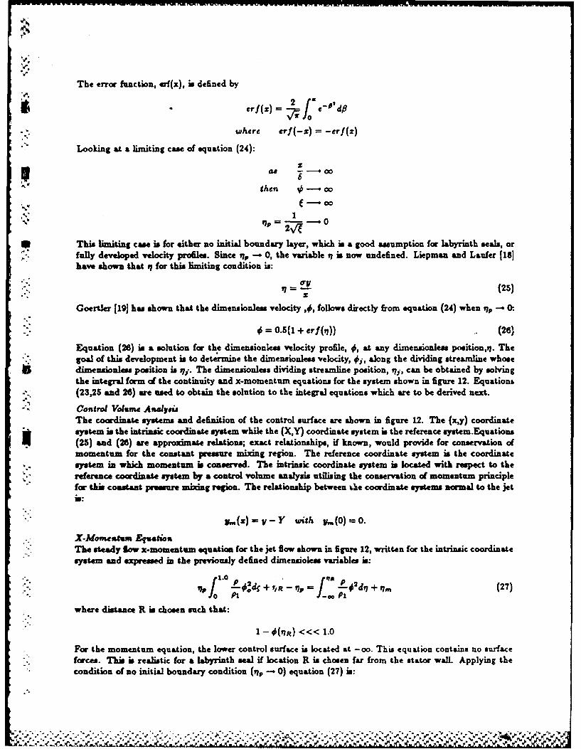
The error function, erf(x), is defined by
erf (z) =
where rf (-Z) = -erf(z)
Looking at a limiting case of equation (24):
then 0-0"0
17P 1" ,' M~lp = ' - --
This limiting case is for either no initial boundary layer, which is a good assumption for labyrinth seals, orfully developed velocity profiles. Since rij -- 0, the variable q is now undefined. Liepman and Laufer [181have shown that q for this limiting condition is:
• - 1 V (25)
Goertler 1191 has shown that the dimensionless velocity ,4, follows directly from equation (24) when tip - 0.
"0 = 0.5(1 + erf(1)) (26)
Equation (26) is a solution for the dimensionless velocity profile, 0, at any dimensionless position,q. Thegoal of this development is to determine the dimensionless velocity, 4j, along the dividing streamline whosedimensionless position is Ply. The dimensionless dividing streamline position, iyj, can be obtained by solvingthe integral form of the continuity and x-momentum equations for the system shown in figure 12. Equations(23,25 and 26) are used to obtain the solution to the integral equations which are to be derived next.
Control Volume Anal .siThe coordinate systems and definition of the control surface are shown in figure 12. The (x,y) coordinatesystem is the intrinsi coordinate system while the (X,Y) coordinate system is the reference system.Equations(25) and (26) are approximate relations; exact relationships, if known, would provide for conservation ofmomentum for the constant pressure mixing region. The reference coordinate system is the coordinatesystem in which momentum is conserved. The intrinsic coordinate system is located with respect to the
K." reference coordinate system by a control volume analysis utilising the conservation of momentum principlefor this constant pressure mixing region. The relationship between tQe coordinate systems normal to the jetis:
y.(z)=Y-Y with p,(0) =0.
* X-Momentuin EquationThe steady low x-momentum equation for the jet flow shown in figure 12, written for the intrinsic coordinatesystem and expressed in the previously defined dimensioless variables is:
,- f -0!4 + , _ = L 'd7 + #. (27)0: P: P,
where distance R is chosen such that:
I - 0(17R) <<< 1.O
For the momentum equation, the lower control surface is located at -co. This equation contains no surface.. forces. This is realistic for a labyrinth seal if location R is chosen far from the stator wall. Applying the
condition of no initial boundary condition (i, - 0) equation (27) is:
2L
'.

. 'elm
1m =9 J - -L2ds7 (28)f' PI
Continuity EquationThe steady flow continuity equation, written for the intrinsic coordinate system and expressed in the previ-
": ously defined dimensionless variables is:
(7 f 1.0 P od + ,t - ,7p Od,7 + IN, (2)PlP fL 1 P(
For the continuity equation,the lower control surface is coincident with the jet dividing streamline. Substi-tuting the results of the momentum equation, equation (27), into equation (28) yields:
Making the assumption of no initial boundary layer (q., - 0), equation (30) becomes:
S.t
=d j.L 2dn (31)
* The density ratio, (p/pa), for isoenergetic tow (constant temperature) is given as:
P (1-a 2 ) (32)
PI (1-C24
( 32)
The final form of the continuity equation becomes:
* _" _ ) [e"
dq (33)-4~f whreC ( C42 02)' C4202)p
where Ca is the Crocco number. Equation (33) can be numerically integrated for a given Crocco numberusing the definition for given in equation (26). The Crocco number is defined as:
Ca2 - (T+(y-)M2) (34)
The Crocco number in a dimensionless velocity simil to the Mach number. The Crocco number uses the' maximum isentropic speed of a gas while the Mach number uses the local speed of sound. The Mach number
varies between 0 andoo while the Crocco number has a range of 0 to 1.
* The solution to equation (33),the location of the dividing streamline, can be obtained by the following step.:0) Calculate the Mach number using the seroth-order leakage value.The seroth-order leakage i discussed
in the next section.1) Calculate the Crocco number using equation (34).2) Substitute equation (26) into equation (33) and integrate the error function. The value of the error
function at the limits R and -co is 1.0, leaving an equation in q- only. This is solved for otj which is thedimensionless location of the dividing streamline.
3) Insert % into equation (26) to obtain the dimensionless velocity along the dividing streamline, 0i.The results of this solution procedure an tabulated in table 2, for air. For air (y L4) flowing in a labyrinthseal, the maximum possible Mach number is 1.0. Therefore, the maximum possible Crocco number is 0.408or Ca 2 = 0.167. The range of solutions is: 4*
0.61632 < O, < 0.6263
Using an average solution of Oe = 0.62 gives a maximum error of less th u 11 percent. The recirculationvelocity at the interface is:
%.6.- -- ,:-.- ... % ' -. ' -.- - .. , ,-.-.. .,, :. ."

U2, = 0.e2U1 (35)
The only remaining prbblem is the numerical definition of W/b. Looking back, equation (11) and equation(26) both describe the axal velocity profile in the jet flowfield. If the following observation is made
t'2
V 1
then equation (35) can be substituted back into equation (12) yielding the following numerical definition for
Y = 0.584 - 0.1340i = 0.5b
It is interesting to note that Jenny et L. [7] assumed that f/b = 0.5.
Figure 13 shows a plot of the dimensionless axial velocity profile in the recirculation region for seal A oftable 1 as alculated by Rhode 12,31. This profile is for the center o the recirculation region to the top dthe labyrinth tooth. The intersection of the two dashed lines is the location and value of the theoreticalrecirculation velocity as calculated using equation (35) and the assumption that the dividing streamlinemakes an angle of 60 with the horisoutal. The agreement is excellent. Again, equation (35) was derivedusing a 2-D theory which neglects the circumferential velocity component. Equation (35) is actually thevelocity at the interface of the two control volumes. The velocity components used in the shear stressequations are all average velocity components. To be consistent, the average recirculation velocity must beused. The CFD results show that the velocity distribution is parabolic in nature. Integrating this yields:
U2 = 0.206U, (38)
Table 2. Tabulated solution to equation (33).
Ca 2 Oi Ca 2 4,,0.00000 0.61632 0.68000 0.675530.05000 0.61915 0.7200 0.681880.10000 0.62211 0.76000 0.689030.15000 0.62523 0.80000 0.697240.20000 0.62848 0.84000 0.706890.24000 0.63129 0.66490 0.7139440.28000 0.63405 0.880 0.7199440.32000 0.63725 0.90250 0.7288340.36000 0.64047 0.92160 0.7349490.40000 0.64387 0.94090 0.7448830.44000 0.64748 0.96040 0.7578690.48000 0.65132 0.9010 0.777432().52000 0.65543 0.992016 0.7987660.56000 0.65979 0.98001 0.8234270.60000 0.8~462 1.000000 1.0000000.64000 0.6982
Reduced Eqtion.The solution of the governing equations can be simplified by reducing the number of equations by one. Thisreduction is accomplished by using equation (2) to eliminate mr from the other equations. The continuityequation for control volume I becomes:
tpAj + ____e + + aWe =0 (37)3 t R. 18 at R42 aO
If equation (37) times the circumferential velocity, W, is now subtracted from equation (3), the followingreduced form of the momentum equation for control volume I is obtained:
% %o

aW, pWIAI aW / apA2 apW2A 2 .+* RAO ) (W, - Wa,)- A 1 - , 1 +t rj 3 / (38)
Similarly, if equation (2) times the circumferential velocity, W2 , is subtracted from equation (4), the reducedmomentum equation for control volume 1 is obtained.
pA2 !W 2 +pW 2 A2 8W 2 +(pA 2 +8pW 2A 2 \ wi-Kat R82 ae at R82af )(3 W.)
= A2 MP + i~GrL
The number of variable is reduced by using the ideal gas law to eliminate the density terms.
P = ,RT (40)
Leakage EquationTo account for the leakage mass low rate in the continuity and momentum equations, the following modelwas chosen.
* mn~=pip~H~V ~(41)
where the kinetic energy carryover coefficient, p is defined by Vermes [201 for straight through seale as:
"2= (1- (42)
- 8.52
w here (L VI -I + 7.23)
and is unity, by definition, for the first tooth of any seal and all the teeth in interlocking and combinationgroove seals. This definition of the carryover coefficient is a local coefficient which can be perturbed in theclearance. The previous analyses by Childs and Scharrer (61 and Jenny et &1 f71 used a global definitionwhich could not be perturbed.
The tow coefficient is defined by Chaplygin 1211 as:
01i wh25~2? ,ere e=y~ ~ - (43)
.-. This flow coefficient yields a different value for each tooth along the seal as has been shown to be the caseby Egli 1221. For choked Bow, Fliegner's formula 1231 will be used for the last seal strip. It is of the form:
.. ,0-- PMcHNc (44)
* Perturbation AnalyisaFor cavity i, the continuity equation (37), momentum equations (38,39) and leakage equation (40) are thegoverning equations for the variables W1j,W 2j,Pn. A perturbation analysis of these equations is to bedeveloped with the eccentricity ratio, e= ,/Cr, selected to be the perturbation parameter. The governingequations re expanded in the perturbation variables:
A & = P,,+elPi H, = Cr, + HH,
Wi = W + AW4l, A = A. + tH
=.. W + CW 2 1.
............ '(*'*%

where e e./Cri is the eccentricity ratio. The seroth-order equations define the leakage mass flow rate andthe circumferential velocity distribution for a centered position. The first-order equations define the per-turbations in presurm nd circumferential velocity due to radial position perturbation of the rotor. Strictlyspeaking, results of a first order analysis are only valid for small motion about a ceutered position.
Zeroth-Order SolutionThe seroth-order leakage equation is
h+I = ri + ,ho (45)
and is used to determine both the leakage-rate, rk. and pressure distribution for a centered position. Theleakage-rate and cavity pressures are determined iteratively, in the following manner. First, determinewhether the flow is choked or not by ssuming that the Mach number at the last tooth is one. Then, knowingthe presure ratio for flow st sonic conditions, the pressmre in the last cavity is found. The mm fow canbe calculated using equation (44). Working backwards towards the first tooth, the rest of the pressures canbe found using equation (41). The final pressure calculation will result in the reservoir pressure necessaryto produce the sonic conditio sat the last tooth. If the actual reservoir pressure is les than this value, thenthe flow is unchoked. Otherwise, it is choked. If the flow is choked, a similar procedure is followed, but nowthe pressure in the last cavity is guessed and a =a" fow rate calculated using equation (44). The remainingpressures are calculated uing equation (41). This is repeated until the calculated reservoir presure equals
. the actual reservoir pressure. If the flow is unchoked, the pressure in the first cavity is guessed and a me"flow rate caklated using equation (41). The remaining pressures are calculated with the same equation.This procedure is repeated until the calculated sump pressure equals the actual sump pressure.
The seroth-order circumferential-momentum equations are
wi- w -) = (r,, - .a )L (46)
r i.. = r,.,ariL (47)
From calculated pressures, the densities can be calculated at each cavity from equation (46), and the onlyunknowns remaining in equations (46) and (47) are the circumferential velocities W1, and W3.j. Given aninlet tangential velocity, a Newton-root-finding approach can be used to solve equations (46) and (47) forthe i-th velocities, one cavity at a time. This is done starting at the first cavity and working downstream.
First-Order SolutionThe governing first-order equations (48,49,50), define the pressure and velocity fluctuations resulting fromthe s clearance function. The continuity and momentum equations follow in order:
,a Psi ap t, _ aw ry, ,. aw .,G '+ G2 r! + +,~
+ G, P 1 - + G7 P1i+ = -G&.H - G.-- Gj H (48)
81i EL x 1w,i aW11.+x~ + XU W2 ,] p +Xi p+ - atat Asa [02 a
+ x~P w ,I+ X..P 1, + X~ja'1 ,1 + xsiW11i + XW 21iR82 as
"% - jfiW1 - XaHt (49)
." _ [YK.~~ Y[YWU + YaW.O t L JU + e - j oe e2 J
Ya -- + Y4,Pj + YjW21, + Y&Pti- + Y,,W 1 , = YzjHjj (50)
where the X's, Y's and G's are defined in Appendix B. These perturbation equations are very different fromthose of Jenny et al. (7J because their analysis neglects pressure perturbations in the leakage and shear stres
* equations, and amumes that the density is constant.
i-" -- -" - --.-,-.''-.-.-.-"''-.,. ''',..-.-''"""""",""; . ,"" ; , .'..',";.".". ', '3''.S' ' 'G%,.,-,...

If the shaft center moves in an elliptical orbit, then the seal clearance function can be defined as:
e = -a cowt coeo - b oinwt ain"S-Jco(8 - Wt) + Co,(6 + wt)] - - Wt) - (a+ wt)(
The pressure and velocity £iuctua;_ms can now be stated in the associated solution format:
P = Pcos(f + wt) + P.m ,sn(f + wt) + P;coe(f - wt) + Pein(f - ,t) (52)w 11 , = W+,ico.(f + wt) + Wj+..sin( + wt) + W;.jco.( - wt) + Wij..r4( - Wt) (53)-' = WIC,.(9 + Wt) + W2.in(f + W) + W~eo.(9 - t) + W ,ift(I - wt) (54)
Substituting equations (51), (52), (53) and (54) into equations (48), (49) and (50) and grouping like termsof sines and cosines (as shown in Appendix C) eliminates the time and theta dependency and yields twelve
,, linear algebraic equations per cavity. The resulting system of equations for the i-th cavity can be stated:
A._II(X-) + I(AI(X,) + IA.+I](X+,) = (B,) + (C,) ()
'- where
(XJ +P +4. IP'I;I -i- W +11.Wi Wi~W+ * -2ci -ii w+ ,++t(X_ 1 ) = (Pa 1 ,P +, _z,.P _,,W ._, _w;_zWTi, _z..: ,, ._,,.:,. _,,Wici_1)
The A matrices and column vectors B and C are given in Appendix C. To use equation (55) for the entiresolution, a system matrix can be formed which is block tridiagonal in the A matrices. The Ose of thisresultant matrix is (12N0 X 12N0) since pressure and velocity perturbations at the inlet and the exit areassumed to be sero. This system is easily solved by various linear equation algorithm, and yield a solutionof the form-
•4 .- !; i+ ; t yL
P; = !TRi + ;!, ..
-. j,;P = !'zi + ! ,..,
• The forte-motion equations for a labyrinth seal are amed to be of the form:
.. KI, (5 )I
The solution of equation (57) for the stiffness and damping coefficients is the objective of the current analysis.The solution procedure used for this analysis is the same one used by Childs and Scharrer [6]. The desiredsolution for the stiffness and damping coefficients is:

NC
K = wRe y(F,, + F..,)L,
NC
NiC (58)
c !R ---I(F., + F.Z ,
NC
rR ° + P---1A
SOLUTION PROCEDURE SUMMARYIn review, the solution procedure uses the following sequential steps:
. a) Determination of whether the ftow is choked or not using equations (41) and().b) The steady-state pressure distribution and leakage are found uing equation (41) and/or (44).c) The steady-state circumferential velocity distribution is determined using equations (48) and (47).d) A system equation is formed for the first-order perturbation variables and solved using the cavity
equation (5).e) Results of this first-order perturbation solution, as defined in equations (56), are inserted into equation
(58) to defined the rotordynamic coefficients.
CONCLUSIONSThis paper has presented a new two-control-volume analysis for the rotordynamic coefficients of labyrinthgas seals which, for the first time, accounts for the recirculation velocity in the s cavity. The analysiswas developed in conjunction with a 2-D CFD model which was used to verify the shear stres and jet flow
$Smodels used. A comparison between the CFD results and the results from the 'bulk flown model of thispaper showed the following:
1) The new two-control-volume model accurately predicts the stator wall shear stres for a teeth-on-rotorlabyrinth seal cavity.
2) The new model predicts the cavity wall shear stress within 25 percent of the CFD results for ateeth-on-rotor labyrinth seal.3 3) The 2-D jet flow theory used in the new model accurately predicts the magnitude of the recirculationvelocity along the dividing streamline.
4) The CFD results show that the mixing length parameter, 1, used in the free shear stres equation isrelatively constant and need not be considered a function of cavity geometry as was assumed by Jenny etal. 171.
The final test of the model, a comparison between experimental results for stiffness and damping coefficientsand the predictions of this model, will be carried out in Part 2 of this paper.
.0"
:.g

NOMENCLATURE
A Crowsectional area of control volume (L2); illustrated in figure (6)B Height of labyrinthseal strip (L); illustratedin figure (5)C Direct damping coefficient (Ft/L)Cr Nominal radial clearance (L); illustrated in figure (5)Dh Hydraulic diameter of cavity (L); introduced in equation (6)H Local radial clearance (L)K Direct stiffness coefficient (F/L)L Pitch of seal strips (L); illustrated in figure (5)NT Number of seal stripsNC=NT-1 Number of cavitiesP Pressure (FIL')R Gas constant (L 2/Tt 2 )Re Radius of control volume (L); illustrated in figure (5)Row Surface velocity of rotor (L/t)T Temperature (T)Tp Tooth tip width (L); illustrated in figure (5)
*U Avexage axial velocity for control volume (L/t); in figure (2)W Average circumferential velocity for control volume (L/t); illustrated in figure (2)W. Average circumferential velocity in the interface between control volumes I and [1 (L/t); introduced in
* equation (18)a,b Radial seal displacement components due to elliptical whirl (L); introduced in equation (51)ar, as Dimensionless length upon which shear stress acts; introduced in equation (3) and (4)c Cross coupled damping coefficient (Ft/L); in equation (57)e. Displacement of the seal rotor from centered position (L)k Cross coupled stiffness coefficient (F/L); in equation (57)m Leakage mass Bow rate per circumferential length (M/Lt)
* .. mr, nr, ms, ns Coefficients for friction factor; in equation (3)t Time (t)v Total velocity (L/t); introduced in equation (11)
,--- w Shaft angular velocity (1/t)p Density of fid (MIL 3
Y Kinematic viscosity (I It)I = 4,/Cr Eccentricity ratioe Turbulent viscosity (Ft/L2); introduced in equation (19)-1 Ratio of specific heats
Al. Subscriptso Zeroth..order componentI First-order component, control volume I value2 Control volume II valuei i-th chamber valuej Value along the dividing streamline
V x X-directiony Y-directionr Reservoir valuea Sump value
4o.
0%

1%
.Z.
REFERENCES1. lwatsubo, T., Matooka, N., and Kawai, R., "Flow Induced Force and Flow Pattern of Labyrinth
Seal,' NASA CP 225Q Proceedings of a workshop at Texas A&M University 10-12 May 1982, EntitledRotordynamni Instability Problems in High Performance Turbomachinery, pp. 205-222.
2. Rhode, D., 'Simulation of Subsonic Flow Through a Generic Labyrinth Seal Cavity,* ASME PaperNo. 85-GT-76.
3. Rhode, D., Private correspondence, Texas A&M University, 1985.4. Stoff, H., 'Incompressible Flow in a Labyrinth Seal,' Journal of Fluid Mechanics , VoL 100, part 4,
pp. 817-829, 1980.5. Iwatsubo, T., 'Evaluation of Instability Forces of Labyrinth Seals in Turbines or Compressors,'
NASA CP 2133 Proceedings of a workshop at Texas A&M University 12-14 May 1980, Entitled RotordynamicInstability Problems in High Performance Turbomachinery, pp. 139-167.
t 6. Childs, D.W., and Scharrer, J.K., *An Iwatsubo Based Solution for Labyrinth Seals: A Comparisonto Experimental Results,* ASME Journal of Exgia.eering for Ga. Turbines and Pouper, April 1986, Vol. 108,
rn pp. 325-3317. Jenny, R.J., Wyasmann, H.P., Pham, T.C., OPrediction of Stiffness and Damping Coefficients for
Centrifugal Compressor Labyrinth Seals," ASME 84-GT-86. Presented at the 29th International Gas TurbineConference and Exhibit, Amsterdam, The Netherlands, June 4-7, 1984.
8. Child, D.W. and Scharrer, J.K., OExperimental Rotordynamic Coefficient Results for Teeth-On-Rotor and Teeth-On-Stator Labyrinth Gas Seals,' ASME Paper No. 86-GT-12.
9. Scharr, J.K., 'A Comparison of Experimental and Theoretical Results for Labyrinth Gas Seals,'PhD Disertation, Texas A&M University, May 1987.
10. Blasius, H., 'Forachungoarb,' Ing.-Wes., No 131, 1913.11. Yamada, Y., Trans. Japan Soc. Mechanical Engineers, VoL 27, No. 180, 1961, pp. 1267.12. Abramovich, G.N., The Theory of Turbulent Jete, MIT Pres, 1963.13. Schlichting, H.,Boundary Layer Theory, McGraw-Hill, pp. 579, 1979.14. Jerie, J., -Flow Through Straight-Through Labyrinth Seals,' Proceedings of the 7th International
Congress on Applied Mechanics, Vol.2, pp. 70-82, 1948.15. Komotori, K. and Mori, H., "Leakage Characteristics of Labyrinth Seals,' Fifth International
Conference on Fluid Sealing, 1971, Paper E4, pp. 45-63.16. Kant, H.H., Page, R.H., and Childs, M.E., Univ. of Illinois Eng. Exp. Report ME TN 392-1, April
1954.17. Korst, H.H. and Tripp, W., 'The Pressure on a Blunt Trailing Edge Separating Two.Supersonic
Two-Dimensional Airstreams of Different Mach Number and Stagnation Pressure But Identical StagnationTemperature,' Proceedings of the Sth Midwestern Conference on Fluid Mechanics, University of MichiganPress, pp. 187-200, 1957.
18. Liepman, H.W. and Lanfer, J., NACA TN1267, 1947.19. Goertler, H., Z. Angew Math. Mech., 22, pp. 244-254, 1942.20. Vermes, G., 'A Fluid Mechanics Approach to the Labyrinth Seal Leakage Problem,' ASME Journal
of Eng eaing for PoMwer, VoL 83 No. 2, April 1961, pp. 161-169.21. Gurevich, M.I.,2. Thlory Of Jets hi As Ideal Fluid, Pergamon Press, 1966, pp. 319-323.
S."22. Egli, A., 'The Leakage of Steam Through Labyrinth Glands," Trans. ASME, VoL 57, 1935, pp.115-122.
23. John, J.E.A, Gas Dynmics, Wylie, 1979.24. Nelson, C.C. and Nguyen, D.T., 'Comparison of Hirs' Equation with Moody's Equation for Deter-
mining Rtordynamic Coefficients of Annular Pressure Seals,' ASME Paper No. 86-TRIB-19, also acceptedfor the ASME Journal of Tribology.
25. Wymmann, H.R., 'Theory and Measurements of Labyrinth Seal Coefficients for Rotor Stability ofTurbocompressors," Proceedings of a workshop at Texas A&M University 2-4 June 1986, Entitled Rotordy-namic Instability Problems in High Performance Turbomachinery (in press).
.. . .. . . .. . . .. . . ..... .. .-. " :...... ....

A PPENDIX A: GO VERNING EQ UA TIONS FOR TEE TH- ON- STA TOR SEA L.4 Reduced Equations
The main difference between the teeth-on-stator equations and the teeth-on-rotor equations occur, in themomentum equations' The shear stresses acting on control volume I are now the rotor shear stress, r,, andthe free shear stress, ry. Similarly, the shear stresses acting on control volume 11 are now the stator shear
'~ ~'stress, r., and the free shear stress, ry. These differences are evident in the reduced form of the continuityand circumferential momentum equations given below:Continuity I
apAj +8pW 1 AI +B pA2 + apW2A2 =0 (Al)
6 + Rs1 80 at R82a6Momentum I
pAB W1+pWIABaW1 + pA2 + apW2A)(. ~( (A2)ri(Wl- ~ =1 + r, - r.arjA
Momentum HI
pA 8W2 + pOW2 A2 8W2 +(8A2 + pW2 A2\,W4(M3)
Ae2 ae "
where as and ar are defined as:
asi = (2B, + Li)/4. ar, = 1.0
The rotor shear stress in the circumferential direction is now defined using the smaller hydraulic diameter
and the velocity components of control volume 1.
1, tVRsi wW02 + U ,Re, W dw - W) +U2D(M)
where Dj 1 , is the hydraulic diameter of C.V. L, defined by:
*Dj 1 = 2Crif/(CrLj) (AS)
Similarly, the stator shear strews in the circumferential direction is now defined using the larger hydraulicdiameter and the velocity components of control volume 11.
where D#,2i is the hydraulic diasseter of C.V. II, defined by:
D, = 2BA41(BA4) (A7)
The definition of the free shear stress remains the same. However, since CFD results were only available* for the teeth-on -rotor configuration, the sensitive mixing length ratio, 11b, may change for a teeth-on-stator
seal.
N6 ,

Zerotft-Ordcr EquationsCon tinuty
=il (AS)Momentum I and II
rh0 ( Wli W 1i 1 ) =(rji. Vr.iae)Li (AS)
U = rL..rL (A1a)
First-Order Equations/ The first-order equations remain exactly the same as before. Since change. were made in the locations and
definitions of the rotor and stator shear stress terms, the following changes in the coefficients of the first-orderequations are necessary:
X'6 o(Wi. - Wi-i..i + Th. (W1 i - Wi i)('0y - 1) Ali (4S1 i - 5)(S 1 . + 1) - LL
Fi fi(I + mr) Ui L. Gr + ri(U2i - Uui)L,( - 1)1- (ReIW - W14)2 + U1 + (Wi - W11)2 + (U2i - Ui,)
[Jr' Uip ~ + luis -)( 1 (Si + 1)] r..ir(I + mr)LI.
xf iz. (W~i - W11...1)P.,...I fh.(W1 . - W'i-.I)U - 1 (4Sj - Pm) .p 2 -P 2 ~ P
- ~ 1wariL. ( + mr) U14 vji(U,4 - Uui)Li(O - 1)1
L( -W ]11)2 + U12 + (W ~j - W 1)2 + (U2 i - U 1)21
U_______i MiUi(4S1 i Ilie -1
X6=ht + ~ar~i+ rjar L ( +mr) (Ruiw - Wi) + irii + TiWiWiURs 1 w - W. (RSIW - W 1)2 + U12 ~ - W. (W2 , - W1 1)2 + (U2 , -l)
Cr, [ 7.O4Cri p 2Cr,2
Y. _U Uipi pli~Ui(4Si~ - 5)b~ 7_4(.+ )p2- P3,4 li+1
K[ri( + M.)4U2 i~asi rj$(U2 i - Uib)L,(0 1.)] + r' (I.4 + Ms)as, L.X W2,+ U2, + (W-WJ2 +(Ui - $i Pi. Pi
W22, 2i W 2 ,- WI, (W 2 -W 1,)2 +(U 2 , U 6 )2
Xf'(i + m.)0U2 1 4Aa,~ + ryj(U 2 i - U1 )L(O - 1)]W 2, W+ U2, (2 ~2+(2 J

APPENDIX B: DEFINITION OF FIRS T- ORDER COEFFICIENTS
A (Cri .) CriwlA BiLW 2 i _P,,,4Cr, P.SEIL.01= RT G2RTR. 1 I RTR*2 G TRs1 G4 RTR82
G5 p2 .p2+ (5~i+1 - 4Sii+d )061~ 06 ypi+i (Pi+
+ 11l(5 -4s1,)(S1 + 1) + pj7 _ p4~.
G's: -m.P.... mhpii(7 - 1) (P(5.. -o =RT0 p2 p,(-S)..- ~l in.wij,( -P)mo~
.? -n 0 0, 1 -mii*(7-1 (5-4 i,) l+ 1); G10 - RTe
vh.(Cr. - Cri+i) _ m.(L. - Tpi) (A 2 1)2 + ______ _______-Ti~) i~
= CriCri~1 17.04Cr2 AN ,1i.(L, 1 p~i)i+l1)Poi~r17.04Ct 2
X, = ;X 2 - r; X = :' -(W.- W 1 )1 =RT ' Ri1 RT
hf - Wi-)P ih.Wii - W,1 ..- 0 - 1)*X4 p2 Pl +i(4Si~ - 5) (Sl. + 1) P
ri~ [ +-i msUiii rpuU(4S- U5)(O - 1) ) aad
-0 W 1 2+ - 1 J.P, 1 (W, - W 11..+)(U2 - 5)
+ h (1+ eUl i. _ r,~j(42 i - 5u)( - 1) 1 js~ sL
p~e~ rass( +m)W + 1)]W~
mf~h(W. - W6.. )P[(- T4( - 1)21 T.w8iL,?PuD)
C.,_ 1.Cr, pi 2Cr?
_ r ri.. ( + m )ULii rAU 2, - U 1)L( -)
Iu. 1 ,, iU(S-)i (~+1](i 2 + U (W2 , - W 1)2 + (U2 , - 1 ) Nr(1m)
-i - p
fiaarL4 aL( + m)wW, ryi~i rji(W2 -l)
Xe=ro + + +
R. ,(Rw-W4 2 +U W. - W1, (W2 - W 1)2 + (U2 , - U 16)2
J.(I --p 4. .

U1,Pi.. u.iU(4S. -Ii(
[C.2i - W2 ) +u, W~- ~ i2X [Ti(l + Mr)-OU 2i4ar. I'i~~ - li)io- 1).]
YT ____IiiA (W - W1 i)
(W2 , W11) -(W 2 , W14)2 + (U, -l)
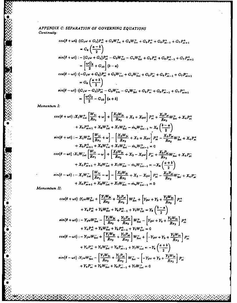
A PPENDIX C: SEPA RA TION OF GO VERNING EQ UA TIONSContinuity:
Coe(e + Wt) :(Giwd + G2 )P~j + G3 WI+4 + G4 W2+. + G6 P,,+ + GOPi- + G 7 P, .+
sn(O + wt): - (GIW + GA)P - G3 WI+,- - G4 W2+. + GSP.1 + GIS.i- + C7 P.I4 1
=G- + GioJ (b -a
coe(e - wt) :(-Glw +i G2 )P~j + G3 W;1 , + G4 Wj~j + G6P; + GsP;-1 + G 7 P+
ein(9 -t):(Gjw -G 2 )P - G3 W; - G4 W~ + G6P i+ G.P;-+G7~+
[=~ - C.] (a + b)
Momentum I:
coev(e+ ut) :X 1 Wj~ Xsw ,ie 1 +w + X2 + X3-] t + R3.W2"" + X 4IFa
X 6 P +1 + X4W+ + XWci -W. X
-~+ w !L-- + X 2 + XWI X, -W. + X 4 p.ei~ewt:-X 1 [ Re, IJ- Re2 J Re2
+ X6P.I+ + XW+.i + X7 W2+.i - r;, 1=i,0
Cos (a - wt) :X1 W;. i- ~w + [j-+ X2 -XsW + . i -. j--W+ X4P,;
+ Xspl; 1 + XGWI-c + X~w;i - riw.-I= 6
esn3e-wt p;1 W X3!~ P,. -. [xX4 p;RS 2 +X2 -X3W]P R 2W~iX
+ XbP;+l + X.Wji + X7W;~j -hW- =0Momemtum II:
r4, YW 2 i Y2P..i 12 ] p+COSVT &Ji1W VWsi R 2 R 2 R 2 J .
+ Y4 P.++ YS W2i+ Y'St.I':-1+ Y WYg
C-( Wt YFVS.W..-R12Wi+Y2J+Y +2 P-
+ b
_ _( t :j Wjj Y _yW2 . Y2 P i ; 21+ Y Y2 W2, pet(9- i):YwW, Re2 R82 Re 2 C
+ Y4P.. + Y6W;*, + YG.,l+YIW.

,
DEFINITION OF MATRIX ELEMENTS
A.. 1 MATRIX
A1.2 = A2,1 = A3.4 = A4,. = G
A 6 .2 = A6. 1 = A,.4 = As.. = X6
A6,6 = A. = A =,, As,7 = -=ho
A, 2 = Alo., = A11.4 = A 12.3 = YG
UThe remaining elements are sero.
Ai MATRIX
A1, = -A 2,2 = Gjw + G 2
A,3 = -A4,4 - ,w + G2A 1 .2 = A 2 ,1 = A, 4 - A 4 ,3 = G=0
A62 = A ,.1 = A.,, = X4
A6- -A2 = XW + X2 +
A,.3 = -A,. = -X3W + X 3 + 2+-----
*1 A,.2 = Ajo. -A11.4 = A12 .3 = Y
" Ag,. = -A1 = Y(, + Y3 + 8--2-
Y3W 2iA11,, -A 1 2,4 = -Y 2W + Y3 +
A1, = -A 2.6 = A3,7 = -A 4 .8 = G,
A6.6 = -A4e = X1 +
A7,7 =-A.,. = X1 - + K J
A6.,e = A.,6 = A,.= Aa. = X4
A,.@ = Aoo, = A11,s = A12.7 = Y7
A1., = A3. 11 = -A 2 ,10 = -A 4. 12 = G4
A.,9 = -A ,10= A,, , = - i . f -A .P =R82
A., 10 - A4,. = A7, 12 = AG,1i = X
A9,, - -Ao.o = Yaw + L + Y'--Re2 R82
A11.11 -A 12 ,1 2 = -Ylw + i + R2-"Re2 R8 2
Aq,1 o = Alo., = A11.12 = A12,1 1 = Y6
The remaining elements are zero.
A.+, MATRIX
A1 2 = A2,1 = A, 4 = A4,3 = G,
The remaining elements are sero.
% %%

B and C Column Vector*
2 2
2 2 2 2
2 2
2 21 2 2 A 3
3 2
B0 C02 2o 0
2 20 0
2 2
. . %
o.0
C,",
0..
-o.5- . 5 5".~
S' - .
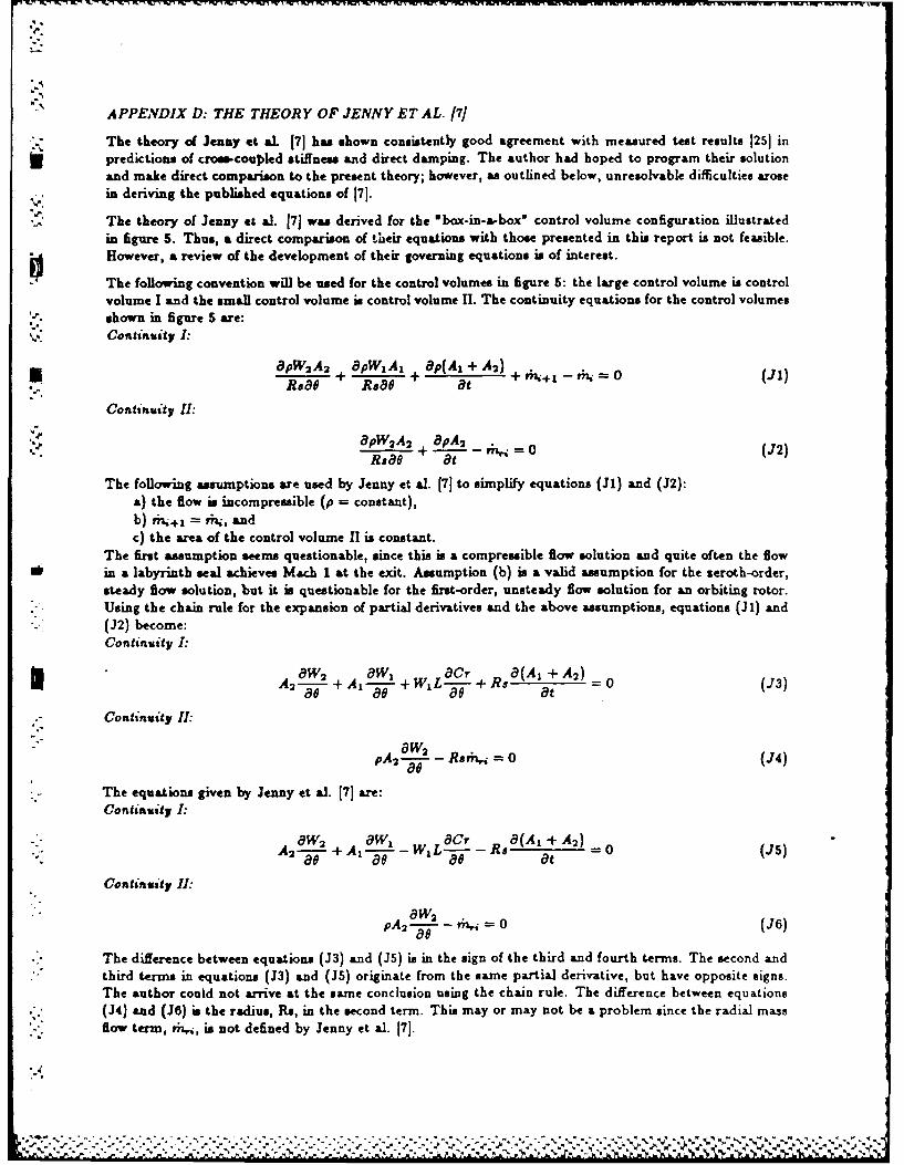
APPENDIX D: THE THEORY OF JENNY ET AL. 17]
*'" The theory of Jenny et aL 171 has shown consistently good agreement with measured test results 1251 inpredictions of cross-coupled stiffness and direct damping. The author had hoped to program their solutionand make direct comparison to the present theory; however, as outlined below, unresolvable difficulties arosein deriving the published equations of [7].
The theory of Jenny et al. 17) was derived for the "box-in-a-box" control volume configuration illustratedin figure 5. Thus, a direct comparison of their equations with those presented in this report is not feasible.However, a review of the development of their governing equations is of interest.
The following convention will be used for the control volumes in figure 5: the large control volume is controlvolume I and the small control volume is control volume II. The continuity equations for the control volumesshown in figure 5 are:
V Continuity I:
.pW 2A2 + pW A + ap(A l + A) + 0 (J1)Ra0+ Rsao at
Continuity II:
apW2A2 + BpA 2 rn,. 0 (J2)Rsae at (2
The following assumptions are used by Jenny et al. [71 to simplify equations (J1) and (J2):a) the flow is incompressible (p = constant),b) +j = ,i, andc) the area of the control volume 11 is constant.
The first assumption seems questionable, since this is a compressible flow solution and quite often the flowIlk in a labyrinth seal achieves Mach 1 at the exit. Assumption (b) is a valid assumption for the seroth-order,
steady flow solution, but it is questionable for the first-order, unsteady flow solution for an orbiting rotor.- Using the chain rule for the expansion of partial derivatives and the above assumptions, equations (3l) and
(J2) become:Continuity I:
W2 + W + Cr (A +A)
8--as- Rsat"=0 (ao3)
Continuity I:
pA-- - Rmtj = 0 (J4)
The equations given by Jenny et al. 17) are:Continuity I:
8W 8 1 Cr R 8 (A + A2)A 2 - + A 12 -o - W -t =0 (J5)80 +s -L-,-- (sat
Continuity 1I:
• -aw2 0
The difference between equations (3) and (J5) is in the sign of the third and fourth terms. The second andthird terms in equations (J3) Lad (JS) originate from the same partial derivative, but have opposite signs.The author could not arrive at the same conclusion using the chain rule. The difference between equations(J4) and (36) is the radius, Rs, in the second term. This may or may not be a problem since the radial massflow term, rhj, is not defined by Jenny et &l. 171.
% %

The author agreed with the derivation of the momentum equations for the control volumes shown in figure
S except for the aforementioned amumptions and the following discrepancies:(a) the axial velocity component is incorporated in the definition of the stator wall shear stress, but
neglected in the definition of the Reynold's number which is used to calculate the friction factor term in theshear stress relation.
(b) the perturbation of the friction factor is ignored. This term has been shown (24] to be important inthe solution for rotordynamic coefficients.
(c) the leakage equation is a global leakage equation. This means that local perturbations pertaining toa cavity can not be found from this equation. Jenny et a1. [7] perturb this global equation for clearance.
(d) the carryover coefficient definition used in the leakage equation is a global equation and cannot beperturbed.
(e) the flow coefficient used in the leakage equation was obtained from a plot of empirical data. Noexplanation was given for the method used to obtain the dervatives of the tow coefficient used in theperturbation equations.
The aforementioned problems prevented the author from obtaining a solution based on the theory of Jennyet &l. 17]. Regrettably, no direct comparison between it and the theory presented in this paper was possible.
5M
.-..
N:-
-.-
0 -
0::-
"-3.'-

Fig. 1 Flow pattern in labyrinth cavity.
SL5TQO,9 &FIT-___ O.... 7A rO ____....7O _
"I - ....------- ' SA -1-V W
I P,
• ,I I
.V ,)VOiOR ,L---------
Fig. 2 Control volumes with Fig. 3 "Box-in-a-box" modelgeometric boundary. of Jenny et al. 7
5 7A70R
>j/ L1, CC> Cr
-"',.W-r,-.R,.
I0 f-IW2, S',
ORFig. 4 Control volumes with Fig. 5 A typical labyrinth
dividing streamline cavity.boundary.

lel
.. A.
we 8 .--.--
Fig. 6 Isometric view ofcontrol volumes. Fig. 7 Pressure forces acting
on control volume I.
IA
t',V
, r L^0.6e
• w/
Fig. 8 Forces acting oncontrol volumes.
Fig. 11 Hodel of semi-contained
turbulent jet.
AL A- .. 0 N. a.
lea
440
.0. -at 1 0l~
85 R~0
-.- ;,o 0R"A .4 .3 . .., ., ., ., ..
*', ."' , .-3 .i .
* Fig. 9 A comparison of CFD Fig. 10 A comparison of CFDand new model for and new model forstator wall shear rotor wall shear stress.stress.
I""'" " ". . . . ....-"- .. -.- -- . -"-"- .- -- " .""-..' ..-. . ."-t- - '. , ., - . ' - " " " "

"N,-.2
.12 L
40
U/'INuu
Fig. 12 Model of half-infinite Fig. 13 Comparison of CFD
turbulent jet. and jet theory resultsfor velocity alongdividing streamline.
..
S,.
..

THEORY VERSUS EXPERIMENT FOR THEROTOR.DYNAMIC COEFFICIENTS OF LABYRINTH GAS SEALS:
PART II - A COMPARISON TO EXPERIMENT 1
DAA W. CHILDSJOSEPH K. SCHARRER
MECHANICAL ENGINEERING DEPAlrrMENTTEXAS A&M UNIVERSITY
COLLEGE STATION, TX 77843
SUMMARYAn experimental test facility is used to measure the leakage and rotordynamic coefficients of teeth-on-
rotor and teeth-on-stator labyrinth gas seals. The test results are presented along with the theoreticallypredicted values for the two seal configurations at three different radial clearances and shaft speeds to 16,000cpm. The test results show that the theory accurately predicts the cross-coupled stiffnms for both sealconfigurations and shows improvement in the prediction of the direct damping for the teeth-on-rotor seal.The theory fails to predict a decrease in the direct damping coefficient for an increase in the radial clearancefor the teeth-on-stator seal
INTRODUCTIONPart 1 of this paper presented a new two-control-volume analysis to predict the rotordynamic coefficients forlabyrinth gas seals. This part (Part 2) of the paper provides a comparison of the predictions of the analysisfrom Part 1 to the new test results for six 'see-through' labyrinth gas seals, as shown in figure 1, three withteeth on the rotor and three with teeth on the stator. The design, development, and operation of the testapparatus and facility, which have been developed to measure the leakage and rotordynamic coefficients of
aannular gas seals, has been described by Childs et al. [1]. The apparatus described in [1] was limited toa top shaft speed of 8,000 cpm. The apparatus has since been redesigned to operate at shaft speeds up to16,000 cpm. A complete discussion of the redesign of the apparatus can be found in Elrod and Childs [2].
As described in [1], the rotordynamic coefficients for a gas seal are defined by the following linearized force-displacement model.
_Fx _ [K_.. Kg. X I+[. C,_ (K,,,v Kri Y -Y EV
Where (X,Y) define the motion of the seal's rotor relative to its stator, (F., F,) are the components of thereaction force acting on the rotor, and (K.., K,,, K., Ky.) and (C.., C,,, C.,, C.) are the stiffness anddamping coefficients respectively. Equation (1) applies for small motion of the rotor about an arbitraryeccentric position. For small motion about a centered position, the following simpler model applies.
-{x=[K 1 k~ +( [ C { } (2)'* Although the test apparatus has the capability of separately identifying the eccentric-position rotordynamic*' coefficients of equation (1), the results presented here are for the centered-position cue only.
PREVIOUS EXPERIMENTAL PROGRAMSA limited amount of experimental data has been published to date on the determination of stiffness and
. damping coefficients for labyrinth gas seals. The first published results for stiffness coefficients were thoseof Wachter and Benckert [3,4,5]. They investigated the following three types of seals: a) teeth-on-stator,b) teeth on the rotor and stator, and c) teeth on the stator and steps or grooves on the rotor. These
'This work was supported in part by NASA Grant NASS-1Si from NASA Lewis Research Center (TechnicalMonitor, Robert Hendricks) and AFOSR Contract F49620-82-K-0033 (Technical Monitor, Tony Amos)

results were limited in that the pressure drop was small, much of the data were for nonrotating seals, nodata were presented for seals with teeth on the rotor, the rotor speed was limited, and tests where rotation
- and inlet tangential velocity existed simultaneously were very scarce. The next investigation was carriedout by Wright [61, who measured an equivalent' radial and tangential stiffness for single-cavity seals withteeth on the stator. AltMough for a very limited and special case, Wright's results do give insight into theeffect of pressure drop, convergence or divergence of the clearance, and forward or backward whirl of aseal. These results could be reduced to direct and cross-coupled stiffness and damping, hence, they are thefirst published damping coefficients for teeth-on-stator labyrinth seals. Brown and Leong 17,81 investigatedthe same seal configurations as Wachter and Benckert, in an effort to verify and extend their work. Their
) results include variations of pressure, geometry, rotor speed, a inlet tangential velocity. Although theinvestigation was extensive, the published results are limited because of the lack of information concerningoperating conditions for the various tests. Childs and Scharrer 19] investigated geometrically similar teeth-on-rotor and teeth-on-stator labyrinth gas seals for stiffness and damping coefficients up to speeds of 6000cpm. Kanemitau and Ohaswa 1101 investigated multistage teeth-on-tator and interlocking labyrinth sealsup to spee& of 2400 cpm. They measured an effective radial and tangential stiffness while varying the whirlfrequency of the rotor. These data could be reduced to stiffness and damping coefficients. Hisa et al. 111)investigated teeth-on-stator seals with 2-4 teeth and a teeth-on-stator seal with steps on the rotor up tospeeds of 6000 cpm. These data only included static tests for direct and cross-coupled stiffness using steam.
The most extensive comparison of analytical predictions and experimental results was carried out by Scharrer(121 using the theory of Childs and Scharrer 1131 and the results of Childs and Scharrer 19]. This comparisonshowed that the theory 1131 predicts cross-coupled stiffness reasonably well, but underpredicts direct stiffness,
* direct damping and cross-coupled damping.
In reviewing previous experimental programs, there is a clear need for a) more extensive testing of teeth-on-rotor labyrinth seals and b) experimental results showing the effect of radial clearance change on directdamping coefficients. This paper addresses these points in addition to evaluating the new analysis presentedin Part 1 of this paper by comparison to the new test results.
TEST APPARATUS AND FACILITYIntroductionThe test results reported here were developed as a part of an extended, joint NASA-USAF funded researchprogram for annular gas seal studies. Tests were carried out on six 'see-through' labyrinth seals, threewith teeth on the rotor and three with teeth on the stator, each with different radial clearances. The test
-.j program had the objective of examining the effects of a change in radial clearance on the leakage and stabilityperformances of a teeth-on-stator and a teeth-on-rotor labyrinth seal. Air is the test fluid.
Test ApparatusThe rotor shaft is suspended pendulum-fashion from an upper, rigidly mounted pivot shaft, as shown in figure2. This arrangement allows a side-to-side (horisontal) motion of the rotor. A cam within the pivot shaftallows vertical positioning of the rotor. The rotor is both positioned and excited horisontally by a hydraulic
* shaker head which acts on the rotor-shaft bearing housing and works against a return spring mounted on theopposite side of the bearing housing. The design of the test rig permits the installation of various rotor/statorcombinations. The stator is supported in the test section housing by three pieso- electric quartz load cellsin a trihedral configuration. The test apparatus measures the reaction-force components and relative sealstator motion. The harmonic components of the motion and force signals are used to identify the stiffnessand damping coefficients. Different seal stator designs are obtained by the use of inserts.
The dimensions and pertinent data for each seal configuration are given in table 1. For the remainder ofthis paper, the seals will be referred to as seal 1, seal 2 and seal 3, as given in table 1, in addition to theirrespective configuration. The smooth and labyrinth inserts used for the 0.4mm (0.016in.) clearance sealsare shown in figure 3. The labyrinth tooth detail for both rotor and stator is shown in figure 4.
Sw.'
.• ..... • .... " .- .-..- •,'.'-'. .. •-.% •.- .~~..........- ,
.,
.. .- . ...... ...-.....- ...... . .-.....- .. .-..-

Table 1. Dimensions of seals tested in this study
Sa Teeth-on-rotor Teeth-on-statori ~seal1 I
Radius, mm 72.5 75.6Length, -m 50.8 50.8Clearance, mm 0.3 0.33Number of teeth 16 16Seal2
S Radius, mm 72.5 75.6Length, mm 50.8 0.8Clearance, mm 0.4 0.4Number of teeth 16 16
-Seal 3Radius, mm 72.5 75.6
* Length, mm 50.8 50.8Clearance, mm 0.55 0.5Number of teeth 16 16
Test Variables*-" When shaking about the centered position, the Dynamic-Seal-Apparstus is capable of controlling the fol-
lowing three independent variables:pressure ratio, rotor speed and inlet eircufnferential welocitj/.Two shakefrequencies, 56.8 Hs and 74.6 Hs, were used during testing with essentially the same results. The results tobe presented were obtained by shaking at 74.6 Hs at an amplitude between 0.076 mm and 0.1 mm. Theactual test points for each of these three independent variables are shown in table 2. When reviewing thefollowing figures, table 2 should be consulted for the definitions of all symbols used.
Table 2. Definition of symbols used in figures
Supply pressure Rotor speeds Inlet circumferential velocities1 3.08 bar 1 3000 cpm 1 High vel. against rotation2 4.46 bar 2 6000 cpm 2 Low veL. against rotation3 5.84 bar 3 9500 cpm 3 Zero circumferential vel.4 7.22 bar 4 13000 cpm 4 Low vel. with rotation5 8.22 bar 5 16000 cpm 5 High vel. with rotation
The reservoir pressures, as measured upstream of the diowmeter, are given in table 2. These values differfrom the actual inlet pressure because of frictional losses and an acceleration of the fluid due to the inletguide vanes. No tests could be run at zero pressure difference, since a small pressure difference is necessaryto keep the rotor fr-,t- ahifti-ev axially and rubbing the inlet guide vanes. Similarly, no zero rotor speed tests
*' were run, since rotor rotation was necessary to prevent damage to the thrust bearing during shaking.
The inlet circumferential velocities are given in figures 5,6 and 7 as a function of pressure ratio. The teeth-on-rotor results are on the left and the teeth-on-stator results are on the right. This convention will be usedfor all of the results presented in this paper. The figures show that inlet circumferential velocity remainsfairly constant over the pressure ratios tested. There were five test points for inlet circumferential velocity;
- two positive, two negative, and one at zero. The sero inlet circumferential velocity point correspondsto the x-axis in the figures 5,6 and 7. The negative numbers shown in the figures mean that the inletcircumferential velocity was opposed to the direction of rotor rotation. The positive numbers mean that theinlet circumferential velocity was in the same direction a rotor rotation. The two different magnitudes ofinlet circumferential velocity, for each direction, correspond to the different inlet guide vane geometries, asdiscussed in Ill. The ratio of inlet circumferential velocity to rotor surface velocity (inlet circumferentialvelocity ratio), ranged from about -6 to about 6. Although the larger numbers are practically unrealistic,they do give insight into the effects of inlet circumferential velocity that would have otherwise gone unnoticed.

4
Normalized ParametersBefore the tests described herein were performed, the TAMU gas seal teat apparatus was modified as de-scribed by Elrod and Childs 121 to allow operation at running speeds up to 16,000 cpm. As expected,subsequent tests revealed a dependence of the rotor diameter on running speed due to inertia and thermaleffects. The rotor growth data, shown in table 3, were obtained from eddy current motion probes positionedat the midapan of the seal. Thus, as the rotor turns faster, the forces in the seal are affected not only by theincreased surface speed of the rotor but also by a change in clearance. Theoretically, normalisation wouldcollapse the data and make the presentation simpler and more straight forward. This was not the case withthe labyrinth seals tested in this study. The failure of the normalization is detailed by Scharrer [14].
Table 3. Growth of rotor with rotational speed
Rotor speed (cpm) Diametrical growth (mm)3000 0.016000 0.029500 0.0313000 0.0516000 0.11
Dynamic ResultsFor a circular orbit of amplitude A, the resultant radial and tangential forces developed by the seal modelof equation (2) are illustrated in figure 8 and are defined by
-FA = K + w,Ft/A = k - Cw
From a stability standpoint, the destabilizing tangential force, F, is of moat interest. The destabilizinginfluence comes from the cross-coupled stiffness, k, and the stabilizing influence comes from the directdamping, C. The radial force usually has little influence on stability, except in rare cases involving multistage'back-to-back' centrifugal compressors with midspan seals where large negative direct stiffness values mayreduce the natural frequencies. Since the focus of this study was on stability, the cros-coupled stiffness anddirect damping results, which have the most influence, will be presented first. The direct stiffness will follow.
Relative UncertaintyBefore proceeding with the results, a statement must be made concerning the uncertainty present in theexperimental results. Using the method described by Holman 1151, the uncertainty in the dynamic coefficientscan be determined. The uncertainty in the force, excitation frequency, and displacement measurements are0.89 N (0.2 lb), 0.13 Hs , and 0.0013 mm, (0.05 mils), respectively. The resulting calculated uncertainty is 7N/mm (40 lb/in) for the stiffness coefficients and 0.0875 N-s/mm (0.5 lb-s/in) for the damping coefficients.Since the measured cross-coupled damping results were rarely greater than the uncertainty, test results arenot provided here for this parameter.
TEST RESULTSIt might seem obvious, since this paper evaluates the effect on seal performance of varying the radial sealclearance, that the data should be presented as a function of clearance (clearance being the x-axis). However,since the inlet circumferential velocity is directly dependent on seal leakage and the seals leakage a differentrates due to differing cross-sectional areas, the inlet circumferential velocity test points for seal 1 differs fromthose of seals 2 and 3. This is a problem because the rotordynamic coefficients are very sensitive to the inletcircumferential velocity. Therefore the dynamic data will be presented as a function of inlet circumferentialvelocity ratio at one pressure and one rotor speed. In the follouing figures, the solid lines represent the testresults and the broken lines represent the analytical predictions.
-" Cross-coupled Stiffness ComparisonFigure 9 shows a comparison of experimental and theoretical results for cross-coupled stiffness versus inletcircumferential velocity ratio for the three seal clearances of table 1. The figure shows that the theory does a
Sgood job of predicting the cross-coupled stiffness for both the teeth-on-rotor and teeth-on-stator seals, at lowrotor speeds. The figure also shows that there is no consistent trend in the cross-coupled results for a change
0%

in clearance. Figure 10 shows a comparison of experimental and theoretical results for cross-coupled stiffnessversus rotor speed for seal I (minimum clearance seal) of table I at the inlet pressures of table 2. The figureshows that the theory correctly predicts a sharp upturn in cross-coupled stiffness at the higher rotor speeds,for the teeth-on-rotor seal. This speed sensitivity was not evident in the low speed results of 191 nor in theresults for seals 2 and 1. The figure also shows that the cros-coupled stiffness for the teeth-on-stator sealdecreases as rotor speed increases. This decrease in cross-coupled stiffneas for an increase in rotor speed wasalso reported by Hisa et al. [Ill for their teeth-on-stator seals. The theory shows the same decrease until thehigher rotor speeds are reached, then it shown a sharp upturn. Thi upturn may appear in the experimentaldata at higher rotor speeds. The same decrease in os-coupled stiffness with an increase in rotor speed wasevident in the results for seals 2 and 3.
Direct Dampmnu OomparsonFigure 11 shows a comparison of experimental and theoretical direct damping versus inlet circumferentialvelocity ratio at the three clearances of table 1. The figure shows that the direct damping coefficient for ateeth-on-rotor seal increases as clearance increases. The theory correctly predicts this trend but underpredictsthe magnitude of the coefficient by 30 percent. The figure also shows that the direct damping coefficientfor a teeth-onu-tator seal decreases as clearance increases. The theory shows the opposite trend. Figure 12shows a comparison of experimental and theoretical direct damping versus rotor speed for seal I of table1 at the inlet pressures of table 2. The figure shows that the teat results show little or no sensitivity torotor speed, for either seal configuration, while the theory shows a sharp upturn at the higher speeds. Thisupturn may be evident in future test results at higher speeds. The results for seals 2 and 3 showed the sameinsensitivity to rotor speed.
Direct Stiffness ComparisonFigure 13 shows a comparison of experimental and theoretical direct stiffnem versus inlet circumferentialvelocity for the seal clearances of table 1. The figure shows that, for both seal configurations, the directstiffness coefficient is negative and increases as radial seal clearance increases. One would expect serodirect stiffness values at sufficiently large clearances. The theory predicts this same trend, for both sealconfigurations. Figure 13 also shows that the theory underpredicts the direct stiffness magnitudes at highrotor speeds. Figure 14 show a comparison of experimental and theoretical direct stiffness versus rotor speedfor seal 1 of table I at the inlet pressures of table 2. The figure shows that the test results, for both sealconfiguration, show little or no sensitivity to rotor speed. The figure also shows that the theory is overlysensitive to rotor speed. The insensitivity to rotor speed was also evident in the test results for seals 2 and3.
Stability AnalsaisOne of the main objectives of this test program was an evaluation of the effect on seal performance of varyingthe radial seal clearance. A comparison of the stability of the two seal configurations at the different radialclearances satisfies that objective. Since a direct comparison of the coefficients of the two seals does notshow any clear stability advantage or the overall effect of a change in the radial seal clearance, anothermethod of comparison must be used. One method in which the dynamic coefficients of the two seals can bedirectly compared is through their respective non-dimensional whirl frequency ratios. Whirl frequency ratioi defined by
Whirl frequency ratio = k/Cw = (fy
where w is the running speed, and nf is the ratio of the destabilizing influence of the cross-coupled stiffnessand the stabilizing influence of direct damping. Faom a stability viewpoint, a minimum whirl ratio isdesirable. Figure 15 shows the whirl frequency ratio versus inlet circumferential velocity ratio for the sealclearances of table 1. For teeth-os-rotor seals, the figure shows that, as the clearance increases, the sealbecomes more stable. For teeth-on-stator seals the opposite is true; as clearance increases the seal becomesles stable, for the positive inlet circumferential velocity case. The figure also shows that the teeth-on-statorseals are more stable that the teeth-on-rotor seals for the positive inlet circumferential velocity ratio, as wasfound previously [91.
"%'
"d"

Comparison to theory of 1131Figures 10 and 17 provide a brief comparison of the present theory to the theory of Childs and Scharrer 1i3].Figure 16 shows cross-coupled stiffns venus pressure ratio for a teeth-on-rotor labyrinth seal at 16,000cpm, and demonstrates that the present theory follows the experimental data more closely than the formertheory 113]. Similarly, Agure 17 shows that the present theory also follows the experimental data for directdamping more closely than the former theory 113].
CONCLUSIONSTest results have been presented for stffnem and damping coefficients for six 'e-through labyrinth seals,three with teeth an the rotor and three with teeth on the stator. The seals were tested under identicaloperating conditions to investigate the influence of rotor speed and the effect of varying the radial sealclearance on the rotordynamk coefficients. These experimental results were compared to the predictionsfrom the new anasis presented in Part 1 of this paper.
The experimental results of the previous section support the following conclusions:(1) For teeth-os-rotor seals, the direct damping increases as clearance increases; for teeth-on-stator
seals, the direct damping decreases as clearances increases.(2) Direct etifnss is negative and increases as clearances increases, for both seal configurations. Cross-
coupled stiffnees showed no consistent trend with respect to clearance changes.(3) Direct stiffness and direct damping show little or no sensitivity to rotor speed up to 16,000 cpm.
Crose-coupled stiffness shows a sharp upswing at higher rotor speeds, for a teeth-on-rotor seal. Cross-coupledstiffness decrease as rotor speed increases, for a teeth-on-stator seal.
(4) Aj clearance decreases, toeth-on-rotor seals become less stable and teeth-on-stator seals becomemore stable, for positive inlet circumferential velocity.
The theoretical results of the previous section support the following conclusions:(1) The theory correctly predicts that direct stiffness is negative and increases as clearance increases, for
both seal configurations. The theory incorrectly predicts an approximately quadratic increase in the directstiffness magnitude (becoming more negative) as speed increases. Test results show scant sensitivity.
(2) The theory accurately predicts an increase in cross-coupled stiffnes at high speeds, for a teeth-on-rotor seal.
(3) For teeth-on-rotor seals, the theory correctly predicts an increase in direct damping for an increasein clearance. However, the theory incorrectly predicts the same trend for a teeth-enstator seal.
(4) The theory incorrectly predicts an approximately quadratic increase in direct damping with runningspeed. Test results show no systematic change in direct damping with running speed.of (5) A comparison with test results for a teeth-on-rotor seal shows that the theory presented in Part Iof this paper does a better job of predicting cross-coupled stiffness and direct damping than does the theoryof Childs and Scharrer 1131.
I
''e
I
o ,
4 -

NOMENCLATURE
A Seal orbit radius (L); ilustrated in figure B.* B Tooth height (L); ilustrated in figure 1.
C~c Direct ad cross-coupled damping coefficients (FT/L)Cr Radial clearance (L); illustrated in figure 1.K,k Direct ad cross-coupled, stiffness coefficients (F/L)F Seal reaction-force (F)L Tooth pitch (L); illustrated in figure 1.Pr Sea in"t pressure (F/L2 )Rs Seal radius (L); ilustrated in figure 1.XYY Rotor to stato relative displacement components (L)(Ilf Whirl frweecy ratiowa Shaft angular velocity (l/T)
Subscrit#i Value in ith cavityr Radial componentt Tagential componentzxy Rectangular coordinate directions

0
REFERENCES1. Childs, D., Nelson, C., Nicks, C., Scharrer, J., Elrod, Hale, K., 'Theory Versus Experiment for the
Rotordynamic Coefficients of Annular Gas Seals: Part 1- Test Facility and Apparatus,* ASME Journal of71Tibolog, July 1986, Vol. 108, pp. 426-432.
2. Elrod, D and -Childs, D., "A Comparison of Experimental and Theoretical Results for Leakage,Pressure Gradients, and Rotordynamic Coefficients for Tapered Annular Gas Seals,' Tex" A&M Turbomachinery Laboratory Report TRC-SEAL-4-86.
3. Wachter, J., and Benckert, H.,'Querkrafte aus Spaltdichtungen-Eine mogliche Uresache fur die Lau-funruhe von Turbomschinen,' Atomkernenerpie,32, 1978, Lfg. 4, pp. 239-246.
4. Wachter, J., and Benckert, H., OFlow Induced Spring Coefficients of Labyrinth Seals for Applicationsin Rotordynamics," NASA CP 2133 Proceedings of a workshop held at Texas A&M University 12-14 May1980, Entitled Rotordynamic Instability Problems of High Performance Turbomachinery, pp. 189-212.
5. Benckert, H., 'Stromungsbedinte Federkennwerte in Labyrinthdichtungen,' Doctoral dissertation atUniversity of Stuttgart, 1980.
6. Wright, D.V., 'Labyrinth Seal Forces on a Whirling Rotor,' Rotor Dynamical Instb&iil, ASME,New York, 1983, pp. 19-31.
7. Brown, R.D, and Leong, Y.M.M.S, 'Experimental Investigation of Lateral Forces Induced by FlowThrough Model Labyrinth Glands,* NASA CP 2338, Rotordynamic Instability Problems in High Perfor-mance Turbomachinery, proceedings of a workshop held at Texas A&M University 28-30 May, 1964. pp.187-2 10.
8. Leong, Y.M.M.S, 'Experimental Investigations of Lateral Forces Induced by Flow Through ModelLabyrinth Glands,- Doctoral Dissertation, Heriot-Watt University, Edinburgh, June 1983.
9. Childs, D. and Scharrer, J, 'Experimental Rotordynamic Coefficient Results for Teeth-On-Rotor and,:. .: Teeth-On-Stator Labyrinth Gas Seals," ASME Paper No. 86-GT-12, Also accepted for ASME Journal of
Engineering for Gas Trbines and Power.10. Kanemitsu, Y. and Ohsawa, M., 'Experimental Study on Flow Induced Force of Labyrinth Seal,"
Proceedings of the Post IFToMM Conference on Flow Induced Force in Rotating Machinery, September18-19, 1986, Kobe University, pp. 106-112.
11. His&, S., Sakakida, H., Asatu, S. and Sakamoto, T., 'Steam Excited Vibration in Rotor-BearingSystem,' Proceedings of the International Conference on Rotordynamics, September 14-17, 1986, Tokoyo,Japan, pp. 635-641.
12. Scharrer, J., 'A Comparison of Experimental and Theoretical Results for Rotordynamic Coefficientsfor Labyrinth Gas Seals," TRC Report No. SEAL-2-85, Texas A&M University, May 1985.
13. Childs, D. and Scharrer, J., 'An Iwatsubo Based Solution for Labyrinth Seals: A Comparison toExperimental Results,' ASME Jounal of Eineering for Gas Trbines and Power, April 1988, Vol. 108,
. pp. 325-331.14. Schaffer, J., 'A Comparison of Experimental and Theoretical Results for Labyrinth Gas Seals,"
Doctoral Dissertation, Texas A&M University, College Station, TX, May 1987.15. Holman, J.P.,Experimental Methods for Enqineer, McGraw-Hill, 1978, pp. 45.
0
0
0
0
,--..-.

Cr
Fig. 1A typical cavity.
U'U
Fig. 2 Test apparatus.

50.8 5
152.
15 .2175.6-165.1
.4. ~~ -4.76i
Fig. 3 Smooth and labyrinth stator inserts for seal 2.
3.175- 1IO.1524
3.7 am~
Fig. 4 Detail of labyrinth tooth.
.~~ ~ ~ ~~ . .. .. . . . . .
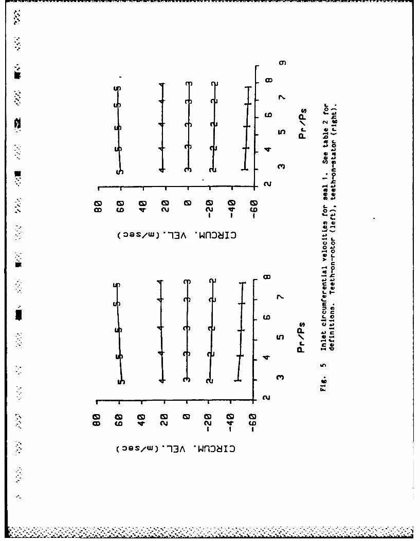
cn)
CD 4C-r~in
a- *
c~:~
(Y)&0
4,
~ CD ('U(U ~ CDcI
0-4--%.
(OIS/WJ) -13A *wflJ8iIJ

I~v 4 L
0 000.&
C
1 . I-
.0@
o -0
-o to IV c w -v w w
OQS/UJ 13A wnD5-

LWo
CDI
CL C~
V LSE4
455Lv* 0
CU ~ %~ i CU C U) ~ 0-w A -
-~S/)13A *wflJaiI c0-0
C
.
I()C
ED L
* 0040L C
CV)
CUj
LI n Ln V)
(DOS/W)* 13A *wflai.

(K +Cw)A
(k -Cw)A
wt
Fig 8 ooso ycrnosyp~an ei

Ln
u CCCDxCSN
_j~ .CD~ .~4J
w a.
LiCL~
ck
IL
u 00 0
In(w/N & F)If &
(D , I - - diid
k CC V
(W/N 4X)VIm CL 4.
*0
w 0 =42 L
0L L
Lx0 0S4
t~-i V-4 A&L c a
V). 4) V) CD C
N * NS4AxA

(S
0C
I ICD Li C6-4 .4
-~~(S I/) : *
CCo 0
CS& 0"(S) -y- L.
(S) 0
E4L,
0.
C 4)L06
U0
aL 04
C D 0 -4.
a.4
CL 0L
EUDC
LiL
is) 0
CD r-d 4- LDL.
Li a
CD .4 (k 4
'~, CD 4

* co0-19 C (D 0
co tv IxJ
CDi 0C L u_ -4 t A
CD LD P- -0D
A, c
LAJL
w* u
ww
M a.
U) CD 9 e:
CL u
I)CD IS (CD 0 CD C CD L
(W0SN XX 1

LI (VCfv (V
in CU0
Cl 1-40 w ' L. C
LAW CD M 0
in C') Cu -
*S C L
(W/S~CN) IX a
IC 1 -4(S) C) CD IS) S) C) IS 4 %..
0 .
-~~ in~C
(S
IID u- 0
-. n (v %-, 0 ~ 3 i
fV)D (V) Cu Cu -
(W/yN LJ
acc

CDO
u a:
*CD
CD >
Li~ "I-
In D__ _ _ _ _ £- %D
U0 c
I~~d V I V-- -. C O
I I I I * 0
CD CD CS) D CS CD D CD CD C
(WW/N) xxA 0
CD ~4 C) - I'
0, g- L. -4o~ -4 0 9.
I r cu a: 1 .2 ,
4) C U C
/;j ej. -j
(W/N c as
OoJ .-. - - -- . .-

* T~~W KflCS)
0 (D
CSI..)
*-4 A)
0- -4)-cl (S) Lj -ItCL
CDL(S)
S0 L
(S) (S S S S S D c S 0 do Ftn () L CS Ln CS)Ln S) n G4) o
_____ ____ ____ ____ ___= (-4-V
LC.
LAa CD 06 tSJ LA.A ) LA II~~S - -u C\ l :C' ?
W 06
(WW/N) )($r(S) L
CS) L
-J 4 j
Li- a. a
IS) C)
(S CJ )
((S)(.0
- ~ m v Ln (D0
. 4(uJW/N) x)().

4%CD
a.C C
ClU X:
Go * 4 j- V 0 10
(Di IS) r
L go
Ln 0in6~ CD
%C0'
J-) 0
XXDI-4 0
Q6c~W o
Wr aa(i *4J C
(S)Li
(D~q IS EL MrL
cle I
a. .n .O u
(SI)
XXDM/AXNi

V ILEIH-ON-R0lOR LABYRINTH St AtSPEED - 16000 CPM
Soo0zWn 450 0t.XPVR1MENTAI. DATA41) ONEW PROGRAM RESULTSJ 1100 dIWATSUDO PROGRAM RESULTSzL&.
tA. 350
0 300
S250
200
150
300
u 0----0 .6 3.2 4.6 6.4 9
.9 2.4 4 5.6 7.2
PRESSURE RATIO
Fig. 16 A comparison of experimental and theoretical* results Of this report with those of [13)
fr cross-coupled stiffness.
TEETH-ON-ROTOR LABYRINTH SEALSPEED- 16000 CPM
500
450 0 EXPERIMENTAL DATA0 NEW PROGRAM RESULTS
1 400 A IWATSU9O PROGRAM RESULTS
350
~d 300
250
* 20
- 100
W 50
*0 1.6 3.2 4.9 6.4 a
.6 2.4 4 5.6 7.2
PRESSURE RATIO
Fig. 17 A comparison of experimental and theoreticalresults of this report with those of [13)
* for direct damping.
&X7
Appendix B
Rhode, D. L. and Hensel, S. J., "Three-Dimensional Computation of Rotordynamic ForceDistributions in aLabyrinth Seal," accepted for presentation at the ASME/AIAA FirstNational Fluid Dynamics Congress, Cincinnati, OH, 24-28 July 1988.
Rhode, D. L. and Hensel, S. J., "Labyrinth Seal Rotordynamic Forces Predicted with aThree-Dimensional Navier-Stokes Computer Code," accepted for presentation at the 24thAIAA/ASEE/ASME/SAE Joint Propulsion Conference, Boston, MA, 11-14 July 1988.
Rhode, D. L. and Nail, G. H., "Computation of Cavity-By-Cavity Flow Development inGeneric Labyrinth Seals," submitted for presentation at the ASME International Comput-ers in Engineering Conference, San Francisco, CA, 31 July - 3 August 1988.
-.3

THREE-DIMENSIONAL COMPUTATION OF ROTORDYNAMIC FORCE DISTRIBUTIONS
IN A LABYRINTH SEAL
JD.L. Rhode* and S.J. Hensel*
-- Turbomachinery Laboratories-,
'N.
Mechanical Engineering Department ,
,.
Texas A&M UniversitynLb o
College Station, Texas 77843
4...
~-
Graduate Student
Associate Professor
%:

0
, ..:: 2
4 ABSTRACT
A numerical method employing a finite difference approach for calculating
the rotordynamic force on eccentric,whirling, labyrinth seals has been developed.
The SIMPLER algorithm along with QUICK differencing is used to calculate the
flowfield within a seal. A modified bipolar coordinate system accurately describes
the geometry of an eccentric seal. The high Reynolds number k - E turbulence
model is utilized, which can handle subsonic compressible or incompressible flows.
A three-percent eccentric single labyrinth cavity rotating at 5,000 c.p.m. was
investigated with three different inlet swirl conditions, each with and without a
whirl orbit frequency of 2500 c.p.m. The fluid was air with an inlet axial velocity
-,", near Mach 0.2. Detailed force, pressure and shear stress distributions within the
cavity are presented. The results indicate that the pressure component accounts
," "" for 99 percent of the rotordynamic force. Whirl seems to have little effect on the
force, and the downstream tooth of the cavity makes a very significant contribution
to this quantity.
0
0
0
?;/.!~,". o
S a-.

3
*NOMENCLATURE
a radius of tooth periphery
b stator radius
c clearance
C convection coefficient
I (turbulence constant
Ct2 turbulence constant
CIA turbulence constant
D diffusion coefficient
dx(i) displacement along general orthogonal coordinate lines
F rotordynamic force
h scale factor
Hi(j) coordinate variation term
k turbulence kinetic energy
I turbulence length scale
L seal cavity pitch
p pressure
P. reference pressure
p" pressure re-defined by Eq. 23
r polar coordinate
s distance
IL xi velocity component
"U, velocity expressed in cartesian tensor notation
U(i) velocity expressed in general orthogonal coordinate system
V x2 velocity component
"- . . .'- . - -. . .. . . .

4
W X 3 velocity component
- , general coordinate expressed in cartesian tensor notation
z general orthogonal coordinate
z transformation variable
A flux coefficient
Cp specific heat
e eccentric distance ratio
H stagnation enthalpy
P production of turbulent kinetic energy
Pr Prandtl numberSS" source term
T temperature
V total velocity
V* reference velocity
a constant
/3 bipolar coordinate parameter
bipolar coordinate parameter
r diffusion coefficient
6,j Kronecker delta
• turbulence energy dissipation
". eccentricity ratio
. polar coordinate
1- viscosity
transformation variable
%- .~

°A.
5
p bipolar coordinate, density
a constant in transport equations
7- stress
r* anisotropic stress
.bipolar coordinate
4'/ general transport quantity
w rotational frequency
. whirling frequency
Subcripts
eff effective (laminar plus turbulent)
" index
in inlet
Sj index
I index
lain laminar
out exit
r radial
t tangential
B bottom face of cell
E east face of cell
N north face of cell
P p-cell node
S south face of cell
T top face of cell
"V west face of cell
-- %
¢ ' .

Superscript
-* nondimnensional quantity
I.'
'4-
-p

7
INTRODUCTION
Labyrinth seals are usually used in pumps, compressors, and turbines to limit
internal leakage. The labyrinth seal was first applied in a steam turbine near the
turn of the century. The idea was to create a flow path between high and low
pressure zones that would convert pressure head into kinetic energy, which was then
dissipated. This was accomplished by a series of cavities. The restriction between
each pair of cavities in the flow path converts the pressure head into mean flow
kinetic energy, and the expansion in the flow path dissipates the kinetic energy by
viscous losses. Figure 1 shows a bank of generic labyrinth cavities and the resulting
streamlines due to leakage. Although seals are very successful in limiting internal
leakage, they are one of the sources of the self-excited vibration of the turbomachine
rotor.
Self-excited vibration is generally subsynchronous, i.e. the rotor whirls within0
it's housing at a frequency below the rotational frequency. This vibration limits
operating speeds and can be extremely destructive to the turbomachine. Although
the physics of the shaft vibration is understood, a quantitative analysis of the forces
which cause the excitation is not complete. The cause of self vibration is a net force
imbalance on the rotor, and this imbalance occurs when the rotor is displaced from
the geometric center of its housing.
Numerous attempts to analyze the destabilizing forces due to leakage through
labyrinth seals have been made. Analytical, numerical, and experimental investi-
gations have been conducted. Most of the analytical models are complex and use
restrictive assumptions. Fujikawa '1] and Jenny [21 used a two-control-volume ana-
lytical approach, and both used empirical data extensively. Iwatsubo [3] considered
time dependent flow area change, but neglected area change in the circumferential

8
direction. Recently, Childs [4,5,6) improved lwatsubo's [3] method and obtained
improved results. Kurohashi [7] introduced a variable flow coefficient for annular seals
and obtained reasonable results for the cross-coupled force. The fluid mechan-
ics associated with an eccentric labyrinth seal may be too complex to accurately
model using an analytical method. Dietzen and Nordman [8] used a finite difference
method in conjuction with a perturbation analysis to determine force coefficients
for annular seals. Although the method appears to be promising, the author did
not compute labyrinth seals. Baumgartner [9, used analytical methods to simplify
the equations, which were then solved numerically. Tam and Przekwas [10] used
a full three-dimensional finite difference analysis and obtained the most detailed
results to date.
Experimental measurements of the rotordynamic coefficients associated with
labyrinth seals are quite scarce. Wachter and Benckert [11,12,131 were the first
to measure stiffness coefficients, but much of the results are for nonrotating seals.
Wright [14] measured single cavity seals with teeth on the rotor. Childs [4,5,6]
appears to have obtained the most comprehensive set of measurements. Rotational
speed, inlet swirl velocity, and pressure drop across the seals were all varied in
these measurements. Seals with teeth on the rotor as well qs teeth on the stator
were used. Rajakumar [15] measured pressure in the circumferential direction and
measured forces at large eccentricities.
COMPUTATIONAL APPROACH
For the present study it has been assumed that the shaft undergoes a circular
whirl orbit, the center of which coincides with that of the housing. Further, a
single cavity of a multi-cavity seal of teeth-on-rotor design as shown in Figure 1 is
considered. Note that the periphery of the teeth and the base of the seal cavity are
W"i
-a.1
a- -
" "" a" "" " " • % " -" ° -" - -.-. "-.. . . . "- ' "- a" • "" .% " ' % a . * "- - % - . a '

9
concentric. Thus, cylindrical coordinates are well suited to describe the geometry
within the seal cavity. However, in the tooth clearance region outside of the cavity,
bipolar coordinates are used because of the eccentricity of the shaft. Specifically,
it is the modified bipolar coordinates which were choosen because they reduce to
cylindrical coordinates in the limit as eccentricity approaches zero. Figure 2 shows
such a finite difference grid within the gap region.
Wood [16] used modified bipolar coordinates to solve the fluid dynamics
associated with eccentric rotating cylinders in general. Consider two circular
cylinders of radii a and b. Let the centers of the two cylinders be a distance ae:,'
apart. If the eccentricity e and the clearance c are defined as
ae: - (1).-? c
and
c (b - a) (2)
then modified bipolar coordinates are defined by the transformation"Z = ( + (3)
. (3)1 + "
z reiO (4)
' pd io (5)
where
-2e[(b/a) 2 - E-c2 + ,/(b 2 /a2 -1 - 2 )2 - 4E21
- 1 (6)
and.. b/a_ 4- -_- (7= l (7)
1 - (b/a)j -
o. - .... 4.*.
- 4.
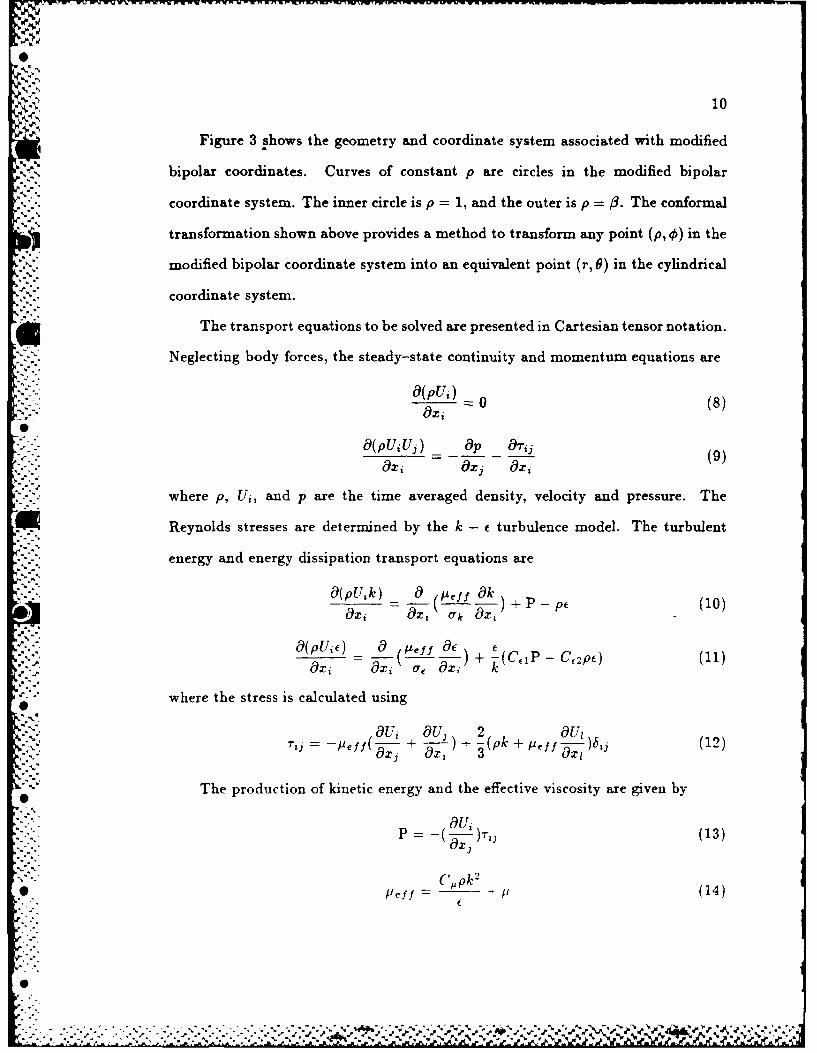
01
Figure 3 shows the geometry and coordinate system associated with modified
bipolar coordinates. Curves of constant p are circles in the modified bipolar
- . coordinate system. The inner circle is p = 1, and the outer is p = 3. The conformal
. transformation shown above provides a method to transform any point (p, 0) in the
modified bipolar coordinate system into an equivalent point (r, 6) in the cylindrical
coordinate system.
The transport equations to be solved are presented in Cartesian tensor notation.
Neglecting body forces, the steady-state continuity and momentum equations are
=O(pU) 0 (8)
Oxi
O(pU U3 ) lOp &i(,-,-.v -(9)Oxi Oxj Oai
where p, U,, and p are the time averaged density, velocity and pressure. The
.-Reynolds stresses are determined by the k - E turbulence model. The turbulent
- energy and energy dissipation transport equations are
O(p, ik) O( /I! O ) + P c (10)
O (pUO) o ( j O
""U" ef) = 0 (L ,) + (CIP - C, 2p) (11).Ox Oxi Of ax, k
where the stress is calculated using
v- 01U, OU, 2 OUtIyff(" + )+ -(pk + [=eff )bj (12)
x, (x1 3 axj
The production of kinetic energy and the effective viscosity are given by
-O (13)Ox,
, 2
C. (,pkSJPeff - p (14)
6dvw..'..........

w~j- . J-wu: -, . -- -= - i: .-- ' -; = J .- , : :. = c -_ ," : = : , : -. -' ,, - -- : . -' -. =, -.-- -- ... 1.
',11
The constants C,,, Ce1 , C, 2 , 9k, and a., are given values of .09,1.44,1.92,1.0,
and 1.217. This is in accordance with the standard !, - model investigated by
Launder and Spalding [17]. For inlet Mach numbers greater than 0.3, the energy
equation must also be employed. The stagnation enthalpy form
a(pUiH) _ (r OH 0 a V2
-(H~- =-[UrI, - r1() (15)
is included whereJuef f- rH - (16)Pr
Static temperature is calculated using
H v
T 2 (17)Cp
The above equations can be transformed into relations using general orthogonal
coordinates. Pope [18] suggests such a procedure using general tensor notation.
Under this procedure the equations retain their original form and simplicity as much
as possible, and they remain in a form where each term has physical significance.
The divergence operator V(i) and coordinate variation term Hi(j) needed to
transform the transport equations into general orthogonal coordinates are
V~i) h, Ihj (18)Ihi dz(i) h,
H1 Oh, (19)- hihj ax,
Here hi represent scale factors and {hi is the product of the scale factors.
Following Pope's 18' transformation procedure. the transport equations become
V(i)pW(i)1 0 (20)
°%Z.
'. ' ' ., _ '. .o ' .' , " - % ., ." . . '- " ' .. ' _ . " ., " ; . -. " - -. . -. " . . " - ". " " - " . , - . . x-L- . J

:: 12
V(i9PU(i)U(j) + r*(ij)']=- + H,1 (j)[pU(i)U(i) + r(ii) (21)49a(j) (1:, - H,(i)[pU(i)U(j) + r(ij)]
MV(i)[pU(i),' - 5 = So (22)
The last equation is a general transport equation for any quantity V,. Note that
the isotropic component of stress has been added to the pressure giving
2 2p = p+ -pk + -#,fV((23)
and r" has the anisotropic stress as
• iOu(i) aU(j).- r'(ij) [ - I ) + - U(i)Hi(j) - 17(.)Hj(i) + 2U(1)Hi(1)ij] (24)
The production of turbulent energy becomes
P U(j) Hj(i) + U(1)Hj(I)bjj]"-" (25)
- - [pk + ef f V(i)U(i)]V(l)U(I)
3
after the transformation to general orthogonal coordinates. All of the transport
equations can be written as
• V(1)[pU(1)g' - r ,)0z) + V(2)[pU(2)V' - " _-2) (26)+ V(3)[pU(3) ' - 3) = S,,
* where all r(,) and S, are defined in Table 1 for the appropriate 4, and U, V, I
correspond to U(1), U(2),U(3).
The algebraic finite difference equations can be easily derived by applying the
* Gauss Divergence theorem to Eq. 26. The integration is performed over the entire
% %°
* -4
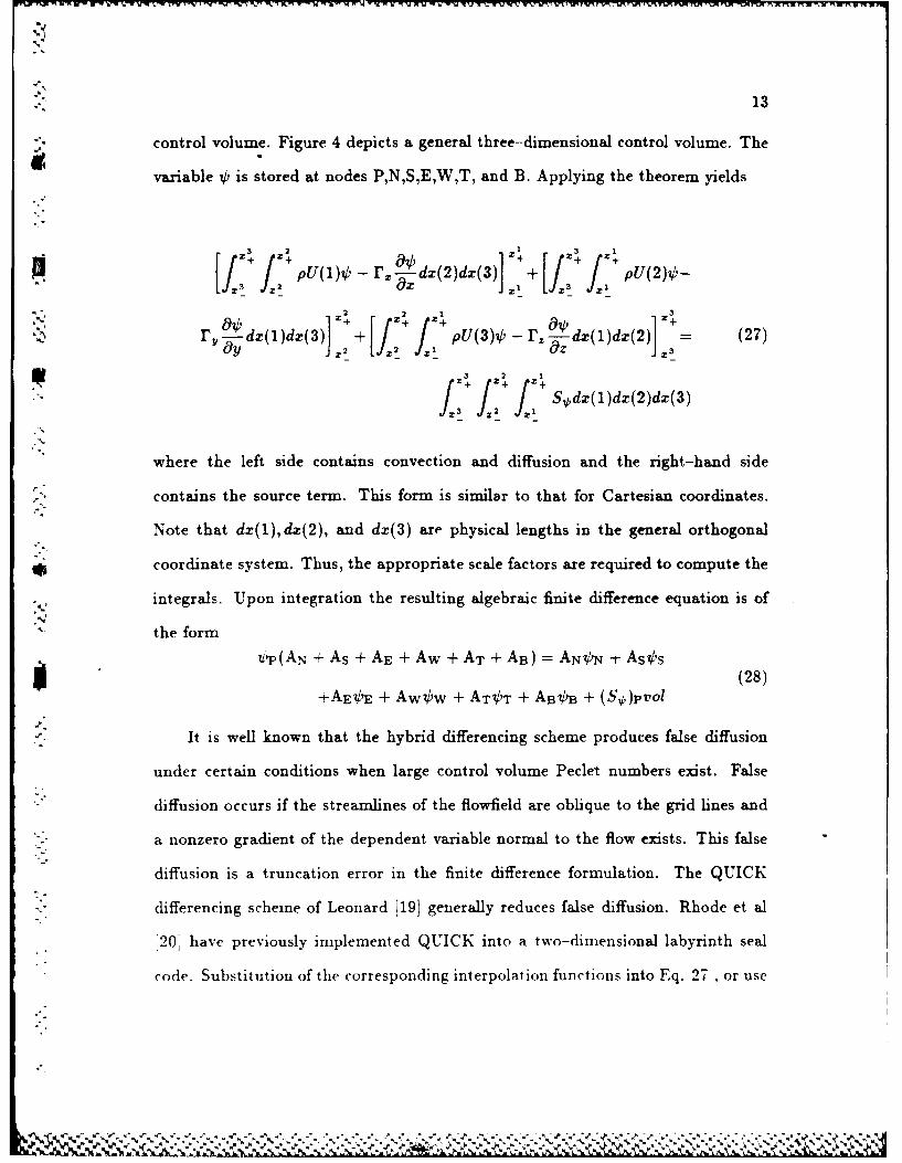
13
control volume. Figure 4 depicts a general three-dimensional control volume. The
variable k is stored at nodes P,N,S,E,W,T, and B. Applying the theorem yields
pu(1)o - r. d(2)d(3)] + [f f2
r. ~Ldx(I)dx(3)] + j~pU(3),b - r. Ldx(l)dax(2)] += (27)
j 3 2.
where the left side contains convection and diffusion and the right-hand side
contains the source term. This form is similar to that for Cartesian coordinates.
Note that dz(1),dz(2), and dx(3) are physical lengths in the general orthogonal
*coordinate system. Thus, the appropriate scale factors are required to compute the
integrals. Upon integration the resulting algebraic finite difference equation is of
the form
U 'P(AN + As + AE + Aw + AT + AB) = ANON + As s
+AEVE + Aww + ATOT + ABOB + (S*)pV(2ol
It is well known that the hybrid differencing scheme produces false diffusion
under certain conditions when large control volume Peclet numbers exist. False
diffusion occurs if the streamlines of the flowfield are oblique to the grid lines and
a nonzero gradient of the dependent variable normal to the flow exists. This false
diffusion is a truncation error in the finite difference formulation. The QUICK
differencing scheme of Leonard [19] generally reduces false diffusion. Rhode et al
20, have previously implemented QUICK into a two-dimensional labyrinth seal
code. Substitution of the corresponding interpolation functions into Eq. 27 , or use
,"2., ",-.: "," '. ,.':'.:-" :'.",'_ ,-.-"-',':.". ":'.:-.' "-:-.'z-'..,-'.'-',','. . . '.'.."".' '..- "'"4:& ;" "," ,L%"

14
of the hybrid upwind-central differencing scheme, yields
E, A,j' + Su (9
Fj A - Sp
where i =E,W,N,S,T,B,EE,WW,NN,SS and the last four neighbors are not needed
if the hybrid scheme is used.
A system of staggered grids is used to store the variables of interest as is done in
the TEACH code [211. The values of pressure, turbulent kinetic energy, turbulence
dissipation, and enthalpy are stored at the intersection points of the primary grid,
whereas each velocity component is stored on a separate grid.
The boundary conditions play an extremely important role in determining
the solution to flow in the labyrinth seal. Wall functions based on the log
law of the wall are used to determine the appropriate shear stress near a wall.
Axial velocity, circumferential velocity, turbulence kinetic energy, and turbulence
dissipation profiles were prescribed at the inlet. All of these inlet profiles were
assumed to be uniform radially. The magnitude of these quantities, except for
circumferential velocity, was determined by executing the program with equivalent
conditions at the inlet and er.it. This case corresponds to a fully developed, i.e.
"% streamwise periodic cavity. From this computer run the circumferential variation of
inlet axial velocity, turbulence energy, and energy dissipation, due to eccentricity,
were all determined. The inlet circumferential velocity profile was also uniform in
the radial direction and varied from case to case. At the circumferential location of
"• largest clearance, this quantity was specified according to the problem of interest.
All other circumferential locations were given an inlet value such that the swirl
velocitv conserved mass in the circumferential direction. The radial velocity was
set to zero at the inlet for all circumferential locations. Pressure was prescribed at
a, . . %2
• I .-- ". '., 4 * ~ ~ ~ ~ * .p

FOR LABYlINTH SEALS (U) TEXAS A AND N UNIV COLLEGED STATIO TU BOMACHINERY LABS D Ni CHILDS ET AL MAR 88
I UNCLASSIFIED AFOSR-TR-88-066 F4628-82-K-033 F/G 13/7 UEEEiE . .iEhEmhohEEmhhEE
EhhhohEEEohhhI

11128 2.
1. mS
1(( 1. 4 1.6
ICRCP RESOUTIO TES CHR
NNN L LI SAPRD c6A
15
one nodal location and its value held constant during the numerical procedure. At
this location pressure had a value of 3 atmospheres. All other pressure nodes were
calculated on a relative basis with respect to this node. The stagnation enthalpy at
the inlet was calculated using the inlet velocities and temperature.
Convection is dominant over diffusion at the exit, and the Hybrid up-
wind/central differencing scheme applied there requires no downstream boundary
values. The axial velocity at the exit was set equal to the axial velocity at the up-
stream node plus a uniformly distributed percentage of the axial velocity increment
required to conserve mass globally.
|4
U
°a
4 4A4 r ,
.. . -, . . . . ' 4*4~* .. 4 4 4 ~ 4 - - ' 4~.'
4 . . . . . . . . . . . . . . . . . . . . . . -

16
RESULTS AND DISCUSSION
The first cavity of a multi-cavity seal is considered throughout this work.
Figure 5 depicts the cavity and shows the relevant dimensions. These dimensions
were chosen because they constitute a generic cavity which is somewhat similar
to those used in high performance turbomachines. Further, this geometry can be
modelled with a uniform grid within the cavity. Due to the coordinate system
arrangement the grid must be nonuniform in the gap region. Minimizing the
grid nonuniformity as much as possible was desireable in aiding convergence. The
eccentricity of the rotor was three percent of the clearance c in this analysis.
-" Computational Characteristics
A total of six converged solutions were obtained. In all six cases the rotational
speed of the rotor was 5,000 cpm. The working fluid was air at 3.0 atm. and
294 K at the inlet. The axial Reynolds number Re = 2U,,c/v in all cases was
19,200, which corresponds to a Mach number near 0.2. The inlet conditions in
all six cases were identical except for swirl velocity. Three different inlet swirl
cases were investigated. These were approximately 30,60, and 90 percent of the
rotational speed of the cavity, which correspond to tangential Reynolds numbers
Reg = 24',,c/v of 1,315, 2,631, and 3,946. Each swirl case was considered with no
whirl as well as half-speed forward whirl, i.e. 2,500 cpm.
A grid dependence study revealed that a grid of 22x22x17 nodes in the x-, r-,
and 9-directions, respectively was sufficient to simulate the flowfield for this seal
problem. Only the number of grid points in the circumferential direction was varied
in the present grid independence study. In order to conserve computer resources,
the number of grid nodes used in the axial and radial directions, 22x22, was chosen
based on extensive previous grid dependence testing [221 at the same Mach number
,4.0
- o
'V°

17Nr
using a concentric-rotor version of the computer program. Grids of 22x22x11,
22x22x17, and 22x22x25 were all used to solve the eccentric cavity whirling at half
speed. All parameters used in the grid dependence study were similar to those used
in the final computations. The 22x22x17 grid was required to determine the grid
independent value for pressure drop across the cavity. The grid-independent results
are presented in Figure 6.
Results
The distribution of the tangential force component within the cavity can be
observed in Figure 7. This plot clearly shows that the downstream tooth contributes
heavily to the total tangential force. Further, the effect of inlet swirl strength on
this force comiponent is only observed at the downstream tooth. This is attributed
to the fact that the circumferential flow is developing within the cavity so that there
, -is a different pressure distribution at the downstream tooth.
For the cases considered here, the radial force generally decreases slightly with
increasing swirl. Note that this force component is not restoring the rotor to its
original position, but is actually pushing it to larger eccentricities. These same
general trends were measured by Leong [23] at small eccentricities. As with the
tangential force, the flow over the downstream tooth significantly influences the net
radial force as seen in Figure 8. Observe that swirl has little effect on the radial
force distribution and that this force is smallest in the middle of the cavity, as for
the tangential force.
It was determined that the net shear stress contribution to the total net radial
force is less than one percent, as is the case with the net tangential force. As
expected, the shear contribution to the radial force was a minimum when 1'," = 0.6
because this is near the asymptotic value in which case there was negligible ,e stress
N N

-wrA?,w unFXJr7MV~NWNM T WW1WW1.TIVVVVWM1Pd
18
on the south wall.
As observed earlier, the pressure force virtually determined the net forces acting
on a seal. The variation of pressure (relative to a reference value given below)
in the circumferential direction at three locations along the rotor are plotted in
Figures 9 through 11. The locations are on the upstream tooth, in the middle
of the cavity, and on the downstream tooth. The reference pressures used to
nondimensionalize the pressure in the polar plots, are 306,000 Pa, .10,400 P., and
321,800 Pa respectively.
As seen in Figure 9, swirl has little effect on pressure at the upstream tooth.
The distribution of pressure is somewhat symmetrical about the axis through 0 =180
degrees. This symmetry indicates that the tangential force component is smaller
than the radial component at the upstream tooth.
In Figure 10 the pressure values are taken at the middle of the south wall of the
cavity. Symmetry about the same axis is also observed, and swirl had little effect
on this. At this mid-cavity location the tangential and radial forces were earlier
seen to be at a minimum. Thus this circumferential pressure distribution is the
closest to being perfectly symmetrical about the axis through 0 = 180 degrees and
that through 9 =90 degrees.
In Figure 11 the pressure distribution on the downstream tooth is given.
Observe that the pressure distribution is not symmetric at all. This shows the large
pressure forces on the downstream tooth seen earlier in Figures 7 and 8. Higher
inlet swirl values increased this lack of symmetry, which caused an increase in the
tangential force.
Although turbomachines frequently whirl at half-speed, the case of no whirl
has also been studied previously 11.12,13]. The F7 distribution along the cavity
-'A -- ft

19
for the no-whirl case was plotted in Figure 12. These results are very similar to
those for half-speed whirl shown in Figure 7. This was expected since for such small
eccentricities the boundary conditions are nearly the same. Figure 13 is the no-
whirl counterpart of Figure 8 for F,. Again, quantitatively as well as qualitatively
the results are very similar to the whirling case.
The Shear Stress
The shear stress distributions along the cavity walls provide previously unavail-
able insight into the basic flowfield. Although they were not found to contribute
significantly to the force components, estimates of these are useful in the develop-
ment of simpler models. Shear stresses are plotted along the wall and in the free
shear layer for a specific theta value. The circumferential variation for a specific
wall location is also given. Thus Figures 14 through 18 can be used to construct
the entire three-dimensional shear stress distribution along the cavity walls and the
free shear layer. Figure 14 shows the points labeled E,F,G, and H which are usedI--"
to denote a specific location in the cavity. For example, wall FG is the south wall
of the cavity, and EH is the free shear layer.
The variation of shear stress along the rotor surface at 0=0 degrees for all
three inlet swirl cases at half-speed whirl can be seen in Figure 15. Although the
-rz component does not vary with inlet swirl, -',-e varies substantially and is largest
for the low inlet swirl case. This is because the Oew/9r term in the expression for
r,, is largest for low inlet swirl, as the shaft tangential velocity is much higher than
that of the fluid. For the case of high inlet swirl, -rr is almost uniform. Note that
*. the stresses are smallest in the corners of the cavity where the turbulence energy
and thus the turbulent viscosity is small.
In Figure 16 the free shear layer stresses are shown. Again, r,. does not vary
e"
'A -
02
with inlet swirl, and stress rro is fairly uniform for the high swirl case. The rO,
stress is highest near the upstream tooth, as this is again a region of very large
OWlar.
The shear stresses along the west wall of the cavity at 0=0 degrees can be seen
in Figure 17. Stress r=, does not vary with inlet swirl, and r~e is largest for the
low inlet swirl case as expected. Stress rze is rather uniform for high swirl, and
the maximum value of r. occurs near the shear layer. The shear stresses along
the east wall of the cavity at 0=0 degrees are presented in Figure 18. The basic
characteristics are generally similar to those in Figure 17. That is r,-, does not vary
[ with inlet swirl, and r2, is largest for low inlet swirl. The maximum of stress r,, is
near the shear layer due to the high turbulence level there.
5-.
-.:.
0
'-%.
% %% 5
, 5 s 5 * 5 %.. 5 *."'. 5
i5 .-. . - . 5' * ~ ''~- - 5
,** I /,*.5 **•"''V P.l:*f~ 5 5.S, % 5 "%% '~ s % V

21
CONCLUSIONS
A computer program has been developed for the prediction of rotordynamic
forces on an eccentric whirling cavity. Eccentricity, shaft speed, whirl rate, and
various inlet conditions can be specified by the user. This work demonstrated that
U numerical methods can be used to determine rotordynamic forces on iabryinth seals,
as well as the bulk flow analytic models used in the past. The solution obtained from
the computer code appeared to be reasonable and contained the expected flowfield
features. Comparison of forces with Leong [22] showed qualitative agreement.
Unfortunately, force measurements for a single teeth-on-rotor labyrinth cavity are
not available for quantitative comparison. However, multi-cavity predictions for
comparison with measurements are forthcoming.
For the present case of one generic cavity at three percent eccentricity, rotating
at 5,000 r.p.m., whirling at 2,500 r.p.m., and with an inlet axial velocity near Mach
0.2, the following can be asserted:
1. An increase in inlet swirl velocity increased the tangential force. The
direction of the force would accelerate the whirl.
U 2. The largest contribution by far to the total tangential force was from the
pressure imbalance on the periphery of the downstream tooth. It is expected
that the tangential force can be affected by altering the geometry of the cavity
at the downstream tooth. Specifically, the thickness and/or geometry of the tooth
periphery is apparently a very important consideration when one is designing a bank
of labyrinth seal cavities in high performance turbomachinery where rotordynamic
instabilities are a problem.
3. The radial force was not restoring the shaft, but was pushing the shaft to
larger eccentricities.

i
22
4. The shear stress made little, nearly one percent, contribution to the total
tangential and radial force.
5. Whirl had a very small effect on the forces.
0A
"S
i '
F'%
.. * - . -.- v
23
ACKNOWLEDGEMENT
The financial support of AFOSR is gratefully acknowledged.

h. 24
REFERENCES
1 Fujikawa, T., Kameoka, T., Abe, T., "A Theoretical Approach to Labyrinth
Seal Forces," in Rotordynamic Instability Problems in High Performance Tur-
bomachinery, Texas A&M University, May 28-30, 1984.
2 Jenny, R. J., Wyssmann, H. P., Pham, T. C., "Prediction of Stiffness and
"I Damping Coefficients for Centrifugal Compressor Labyrinth Seals," in ASME
International Gas Turbine Conference and Ezhibit, Amsterdam, Netherlands.
June 4-7, 1984.
3 Iwatsubo, T., "Evaluation of Instability Forces of Labyrinth Seals in Turbines
or Compressors," in Rotordynamic Instability Problems in High Performance
Turbomachinery, Texas A&M University, May 12-14 1980.
4 Childs, D. W. and Scharrer, J. K., "An Iwatsubo-Based Solution For Labyrinth
Seals," in ASME International Gas Turbine Conference, Houston, 1985.
5 childs, D. W. and Scharrer, J. K., "Theory Versus Experiment For The
Rotordynamic Coefficients Of Labyrinth Gas Seals:Part 1-A Two Control
Volume Model," in ASME Bienniel Conference on Mechanical Vibrations and
Noise, Boston, 1987.
6 childs, D. W. and Scharrer, J. K., "Theory Versus Experiment For The
Rotordynamic Coefficients Of Labyrinth Gas Seals:Part 2-A Two Comparison
To Experiment," in ASME Bienniel Conference on Mechanical Vibrations and
$ , Noise, Boston, 1987.
7 Kurohashi. M., Inoue, Y., Abe, T. and Fujikawa, T., "Spring and Damping
Coefficients of the Labyrinth Seal." in Second International Conference on
Vibrations in Rotating Machinery, Cambridge. England, 1980.
IV % .0 ..
" ,d
+

25
8 Dietzen, F. J., and Nordman, R., "Calculating Rotordynainic Coefficients of
Seals by Finite Difference Techniques," in Rotordy~namic Instability, Pro blems
in High Performance Turbomachinery, Texas A&M University, 1986.
9 Baumgartner, M., "Evaluation Of Exciting Forces In Turbomachinery Induced
By Flow In Labyrinth Seals," in ASME Biennial Conference on Mechanical
Vibrations and Noise, Boston, 1987.
10 Tam, L. T., and Przekwas, A. 3., "Numerical And Analytical Study Of Fluid
Dynamic Forces In Seals And Bearings." in ASME Biennial Conference on
Mechanical Vibrations and Noise, Boston, 1987.
11 Wachter. 3., and Benckert, H., "Querkrafte aus Spaltdichtungen-Eine Mogliche
Ursache fur die Laufunruhe von Turbomaschinen," Atomnkernenergie, vol. 32,
pp. 239-246. 1978.
12 Wachter, 3., and Benckert, H., "Flow Induced Spring Coefficients of Labyrinth
Seals for Applications in Rotordynamic," in Rotordynamic Instability Problems
of High Performance Turbo machinery, Texas A&M University, May 12-14,
1980.
13 Benckert, H.. "Stromungsbedinte Federkennwerte in Labyrinthdichtungen,"
Research Report, Doctoral dissertation, University of Stuttgart, 1980.
14 Wright, D.V., "Labyrinth Seal Forces on a Whirling rotor," in ASME Ap-
plied Mechanics, Bivengineering. and Fluids Engineering Conference, Houston,
Texas. June 20-22. 1983.
15 Rajakumiar. C.. "Experimental Investigations Of Rotor Whirl Excitation Forces
Induced By Labyrinth Seal Flow." in A SME Bienniel Conference on Mechanical
Vibrations and Noie, Boston, 1987.
- - - . - ... ~ . .. , - .. . - -. '.%

26
16 Wood, W. W., "The Asymptotic Expansions at Large Reynolds Numbers for
Steady Motion Between Non-Coaxial Rotating Cylinders," Journal of Fluid
Mechanics, vol. 3, pp. 159-175, 1959.
17 Launder, B. E., and Spalding, D. B., Mathematical Models of Turbulence.
London: Academic Press, 1972.
A18 Pope, S. B., "The Calculation of Turbulent Recirculating Flows In General Or-
thogonal Coordinates," Journal of Computational Physics, vol. 26, pp. 197-217,
1978.
19 Leonard, B. P., "A Stable and Accurate Convective Modelling Procedure Based
on Quadratic Upstream Interpolation," Computational Methods Appl. Mech.
Engr., vol. 19, pp. 59-98, 1979.
* 20 Rhode, D. L., and Sobolik, S. R., "Simulation Of Subsonic Flow Through
A Generic Labyrinth Seal," in ASME International Gas Turbine Conference,
Houston, Texas, 1985.
21 Gosman, A. D. and Pun, W. M., "Calculation of Recirculating Flows," Research
Report, Report no. HTS/74/2, Dept. of Mech. Eng., Imperial College, London,
England., 1974.
22 Nail, G.H., "Leakage Prediction in Compressible Flow Labyrinth Seals," Re-
search Report, Master's Thesis, Texas A&M University, College Station, Texas.
December 1986.
23 Leong, Y.M.M.S., "Experimental Forces Induced by Flow Through Model
Labyrinth Glands." Research Report, Ph.D. Dissertation, Heriot-Watt Univer-
sity, Edinburgh. June 1983.
0t

Table I Diffusion Coefficientsand Source Terms in the Transport Equations
1 0 0
( ) + (1 ( I z(I)
71V2) [yia'+ 2,4I '112(3)1 + V(3)r, L o V H2(3) - VH 3 (2))]. l." 7 1"(2) +2 IH() ~ a--g2)
at - /p ) +H3(2) plT"2 - 2p + VH,(2))]
-H 2 (3) PVIV - i( o3 + o(2) - VH 2 (3)- IrH3(2))1 V(2)[ ,___L_(" _ VH 2 (3) - 11-H3(2))]
+V(3) P9"' + 2VH2 +V(1V- H3
+H 2 (3) pV2 - 2"1( -- l) + 11H 2 (3))
-H 3 (2)[pVi1' - p(-- + a(2- - VH 2 (3)- WVH 3 (2))]
k P -pE
. '(C, IP - CP2)
H 1 P- [V(2) - H- 7(2)V2 + V(3) -u- V(3)V 2 + 7(1)-a-V(1)V 2 ]CH. 2 7 OH
aH
+- +V [7(2)2,- L+ 11-H 2 (3))+7'(3)#(o-V(+a3(2)
+3i o ,-v ° __ o ')a" " [~ 9a(1) a,
+7()(_____ ow - (2))
8z(3) z (2) 2(3)
+"(3)2t( a"' + l1" 3 (2)) + V(1)p( 8 'u + oU)""-" +U 7"(2)/.T('9v + a-u)( + at3)( ,- (i° + K- ,)t
±LT [(2)[(l) ± 8(2)) + (3j(' 1 + z(3))
.- : +ez(1 )2]
'-U.
U-,
U- .
," ," UUUU. UU'%." :.- " -'' -. """- .'U.""'U. ". ': . " " . ."". "... . . . -. "..".".".".-"-". ..-. '-". - - ' "-'," "

- ---- - --- ~ .
Stator Housing
Rotating Surface-/
I.. m
:Fig. 1 Resulting streamlines due to leakage flow in a labyrinth seal
:.
r _
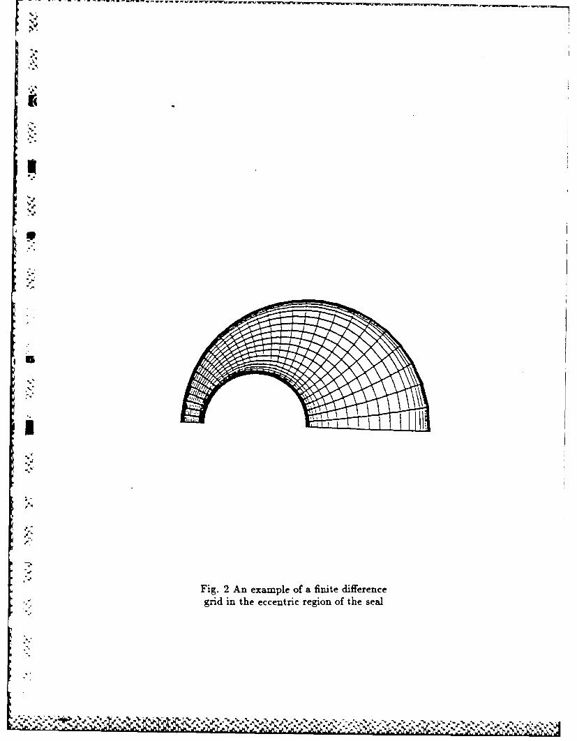
.-
I
Fig. 2 An example of a finite differencei':- grid in the eccentric region of the seal
A>
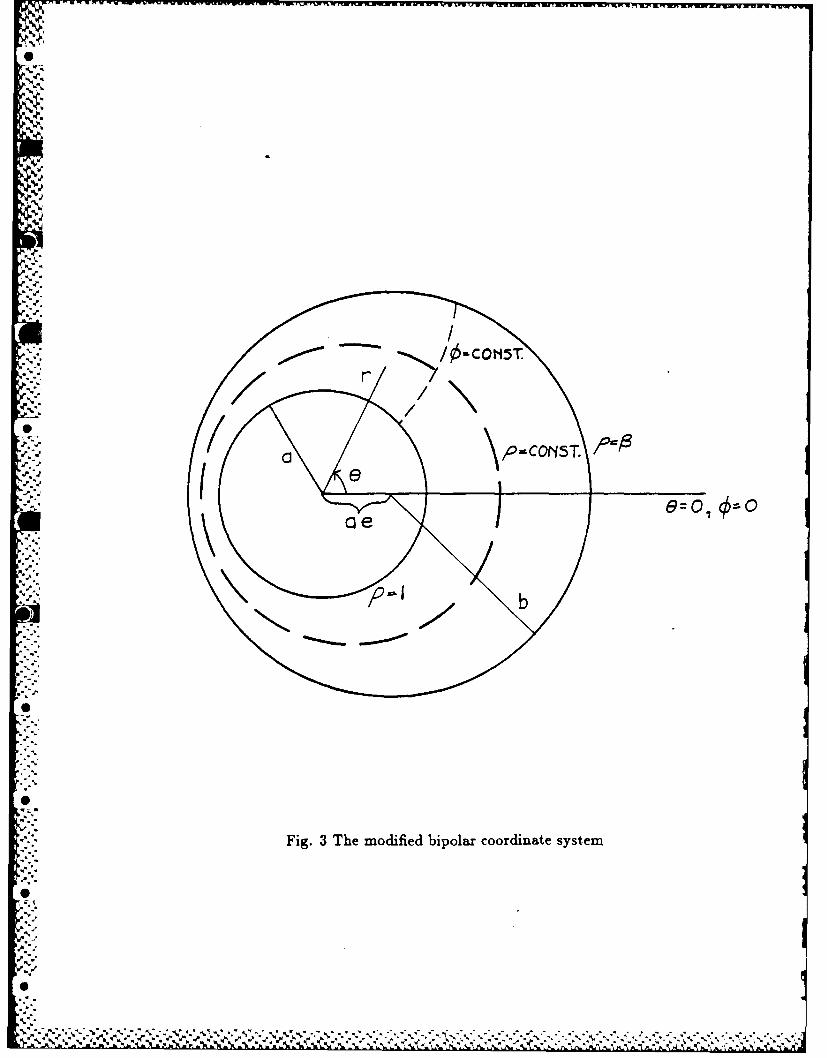
0
Fi.3Temdfidbplrcoriaesse
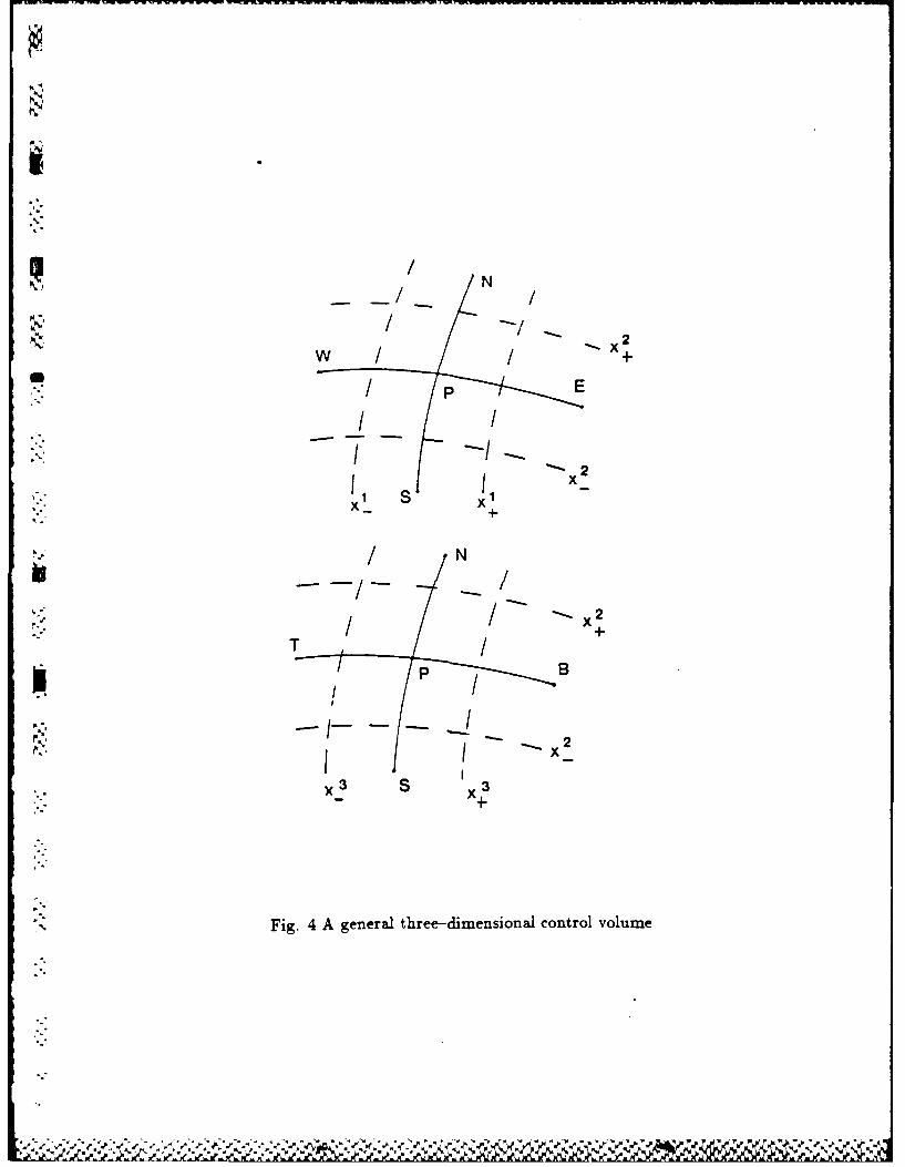
NN
w x2
x 2
-:/ N
15: --//
I / -" 2
p T
B
- I
Fig. 4 A general three-dimensional control volume
".4
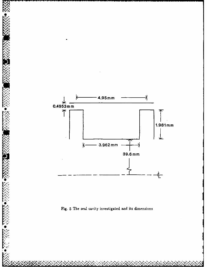
AAN
0
'. 1.91m
1 4" .952mm -
ii 1.981mm
39.6 m
,d-;
m'.. 1
,'
,r"
4' ,,0.,%

.
1.65
, 1.6x
< 1.55
1.5
5 7 9 11 13GRID POINTS X 10
"p.
Fig. 6 The effect of the number of grid nodes on cavity pressure drop
e- w
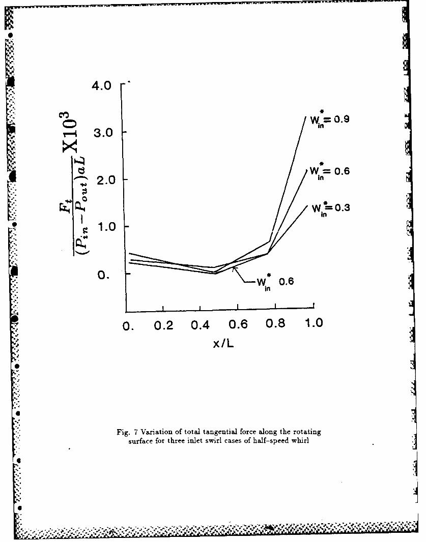
I p0
4.0 -
= 3.0
w=o.6.:. 2.0 in
In', W -=0.3
in
1.0
0. 0in
'I I I I I
0. 0.2 0.4 0.6 0.8 1.0
x/L
Fig. 7 Variation of total tangential force along the rotatingsurface for three inlet swirl cases of half-speed whirl
S.
6"'
* SS,
p. ..

ii 4.0
WW0.9 W= 0.33.0
W 0.6
2.0
"' 1.0
0 . I , I I
0. 0.2 0.4 0.6 0.8 1.0x/L
t
Fig. 8 Variation of total radial force along the rotatingsurface for three inlet swirl cases of half-speed whirl
B

go0
12600
• J
ISO a 30
W* = 0.3in
18000.0.0. g1. . 0
W00.
inn240
300270
.80
0
Fig. 9 Polar plot of the variation of relative pressure around theperiphery of the upstream tooth for three inlet swirl cases at half-speed whirl
S' "J ,0
330
/ .

90° 0
150
s-0.148 0. 15 Fr
210 0 3300
.4
0 02700
Fig. 10 Polar plot of the variation of relative pressure around the"TY "--.0 . %
iperiphery of the rotor at mid-cavity for three inlet swirl cases at half-speed whirl
'o

1200Ws
150 300=0
180S0O9 0.506 00
00
Iin
24
Fig. 11 Polar plot of the variation of relative pressu re around theperiphery of the downstream tooth for three inlet swirl cases at half-speed whirl
-e%"

win =0. 93.0
W. 0.62.0 n
W 0.3
1.0 Wrn
C 0.
-1.0 1
0. 0.2 0.4 0.6 0.8 1.0x/L
Fig. 12 Variation of total tangential force along the
rotating surface for three inlet swirl cases with no whirl
... .I
o. - - .
U - - UU - -

.4.0
:* 4.0 -
W n 0.93.0
WW 0.6
Z,2.0
.:, I 1.0
_O . I I I I
0. 0.2 0.4 0.6 0.8 1.0
x/L
10
. : Fig. 13 Variation of total radial force along the
rotating surface for three inlet swirl cases with no whirl
.1 WI e. .I
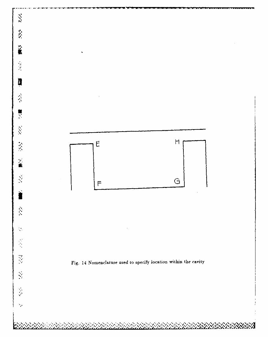
*j N
ii0
,': Fig. 14 Nomenclature used to specify location within the cavity
.NA

-2.011.0
'--' -2.9.0
-1.5it -7.0 =
-1.0 504.'.:-"5.0•3-0.5 3.0
0.
F GPOSITION
* Fig. 15 Variation of shear stress along
the rotor surface at 9 = 0 degrees for cases A,B, and Cn( = 0.3,0.6, and 0.9 respectively) at half-speed whirl
0i:!
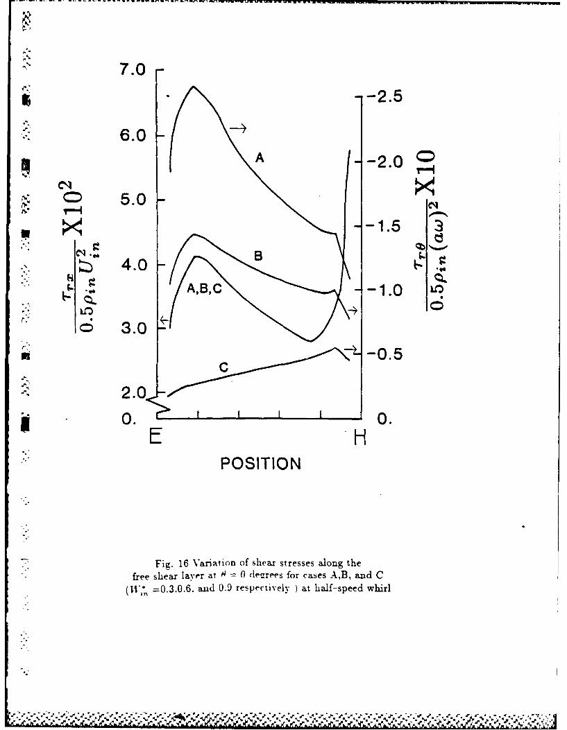
7.0
-- 2.5
.-. 6.0
A -2.0
5.0, × -1.53
: 4.0A,B,C1.0
LCD
3.0-0.5
CJ.
2.0
0. 0.E HPOSITION
Fig. 16 Variation of shear stresses along the
free shear layer at (0 dearees for cases A,B, and C(1I, =0.3.0.6. and 0.9 respectively ) at half-speed whirl

7.0 - -13.0
6.0 -A,B,C -11.0
5.0 9.0
"4.0 7.0 CD
3.0 5.0
, 2.0 3.0
UC6 1.0 -1.0
0. 0.FE
POSITION
* Fig. 17 Variation of shear stresses along theupstream tooth at 0 = 0 degrees for cases AB, and C(1,] =0.3.0.6. and 0.9 respectively) at half-speed whirl
0>
1:1
6 -'I

3.0
* --2.0
-~ C -2.00
-1.0 -1.
-2.0.00.
* -3.0 1
GH
POSITION
Fig. 18 Variation of shear stresses along thedownstream tooth at 9 = 0 degrees for cases A,B, and C(W1* =0.3.0.6, and 0.9 respectively) at half-speed whirl

LABYRINTH SEAL ROTORDYNAMIC FORCES PREDICTED WITH A
THREE-DIMENSIONAL NAVIER-STOKES COMPUTER CODE
D.L. Rhode" and S.J. Hensel*
Turbomachinery Laboratories
Mechanical Engineering Department
Texas A&M University
College Station, Texas 77843
Graduate Student
" Associate Professor
f<
°-p'
.1 - ' - " - -- " . . """ + . "" """ "". . . . . . . , . ." , .. -' -,-, ',. . , i '/. % -' "'% . . . % =

)'Ku
2
ABSTRACT
A finite difference method for determining rotordynamic forces on an eccentric
whirling labyrinth cavity has been developed. A coordinate transformation was
applied to the turbulent flow Navier-Stokes equations in order to use the modified
bipolar coordinate system. The SIMPLER algorithm with QUICK differencing and
the high Reynolds number k-c turbulence model are used to compute the complex
turbulent flowfield. A circular whirl orbit about the geometric center of the housing
was specified for simplicity. For the cases considered, the radial and tangential
force components increased and decreased, respectively, with increasing inlet swirl.
Also, circumferential pressure variations are included for enhanced insight into the
flowfield. Further, the circumferential variation of both shear stress components
along each surface of the cavity are presented to allow the developers of various...
bulk flow models to refine their stress modelling.
4
* '
I
tl '
,I

%V
3
NOMENCLATURE
a radius of tooth periphery
dx(i) displacement along general orthogonal coordinate lines
F rotordynamic force
h scale factor
Hi(j) coordinate variation term
k turbulence kinetic energy
L seal cavity pitch
p pressure
: ppressure re-defined by Eq. 9
r polar coordinate
s distance
.-U x velocity component
Ui velocity expressed in cartesian tensor notation
U(i) velocity expressed in general orthogonal coordinate system
V X2 velocity component
II x3 velocity component
"X, general coordinate expressed in cartesian tensor notation
X? general orthogonal coordinate
A flux coefficient
SP source term
S" source term
r diffusion coefficient
6,j Kronecker delta
turbulence energy dissipation
%-

4
6 .polar coordinate
viscosity
p density
stress
anisotropic stress
general transport quantity
w rotational frequency
Subscripts
eff effective (laminar plus turbulent)
.i index
in inlet
j index
1 index
out out
r radial
sh shaft
" tangential
B bottom face of cell
E east face of cell
N north face of cell
P p-cell node
S south face of cell
T top face of cell
•W west face of cell
Superscript
-Zf1*+i~

5
* nondimensional quantity
U
.1~
P.
'p
-p
p..
~ *.*****.~*~ ~** 9 .~.r * ~ ~* * . ~ .. I.~ ~ ~ . -A1~~ ~&~~kAk&~AkAk&k'

6
INTRODUCTION
,h Self-excited vibration remains a serious problem encountered in high perfor-
mance turbomachines. A complete quantitative analysis of the excitation forces
causing such vibration is still not comAete. The excitation forces result from the
displacement of the rotor from its geometric center in the housing. This displace-
ment often results from a small mass imbalance on the rotor. The result of the
self-excited forces is usually subsynchronous whirl. Subsynchronous whirl (whirling
at a frequency below the rotational frequency of the shaft) may occur in the same
direction as the shaft rotation or in the opposite direction. One source of these
self--excited forces is labyrinth seals.
Labyrinth seals are used to limit internal leakage from high to adjacent low
<.[. pressure regions in a turbomachine. They consist of a highly frictional flow path
" between the rotor and stator. The flow path converts pressure head into mean flow
%. kinetic energy, which is dissipated by viscous losses. Figure 1 shows the streamlines
within a short bank of labyrinth cavities.
A number of analytical investigations on the destablizing forces generated by
the leakage flow through labyrinth seals have been performed. Many of the analvti-
cal methods employ bulk flow models and use numerous empirical correlations. The
problem was first modelled by Alford [1], who neglected circumferential flow, result-
ing in no predicted force. The calculations of Kostyuk [2] neglected the change of
chamber area due to rotor eccentricity and contradicted various force measurements.
Iwatsubo [3,4] extended Kostyuk's model to include this chamber area variation.
Childs and Scharrer [5] included this variation and developed improved shear stress
relationships. They obtained generally improved predictions. These investigators
also presented [6] the first complete set of separate experimental values for the
0

I...
7
stiffness and damping coefficients.
Only very recently has Computational Fluid Dynamics CFD been utilized
to predict the forces on labyrinth seals. Dietzen and Nordman [7] used it in a
hybrid perturbation/CFD model to solve the Navier-Stokes equations for turbulent
flow. Wyssman [8] was apparently the first to present pressure distributions for
an eccentric-rotor labyrinth cavity from a three-dimensional computation of the
turbulent Navier-Stokes equations. These along with velocity distributions given
. by Wyssman, et al [9] were used to develop a special two-control-volume bulk-flow
model. Tam, et al [10] used a three-dimensional CFD code to compute the forces
in non-labyrinth, i.e. annular seals.
NUMERICAL MODEL
In this study the whirl orbit has been idealized as circular motion, the center
of which coincides with that of the housing. A single cavity of a multi-cavity seal
of teeth-on-rotor design is analyzed. Since the tooth perimeter is concentric with
the base of the seal cavity, cylindrical coordinates are the natural choice within
the seal cavity. However, in the clearance region between the teeth and the stator,
bipolar coordinates are used because of the eccentricity of the shaft. Specifically,
the modified bipolar coordinate system was selected as it becomes the cylindrical
coordinate system in the limit as eccentricity approaches zero. Figure 2 shows
such a finite difference grid within the clearance region. Reference [11] gives details
concerning the modified bipolar coordinate system.
Neglecting body forces, the steady-state continuity and momentum equations
Vare
-.- 0 (1)
- w")ax 0
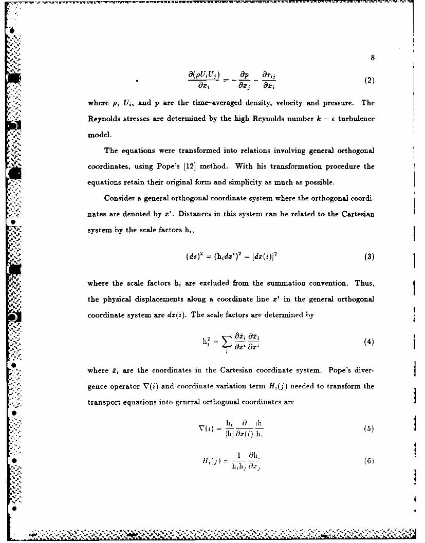
8
O9(puiuj) _ I Op - re, (2)OOxj Ox
i,. .,
wher ppV U, an pp arOh im-vrge est, vlct n rsue h
Reynolds stresses are determined by the high Reynolds number k - f turbulence
N-I model.
% The equations were transformed into relations involving general orthogonal
coordinates, using Pope's [121 method. With his transformation procedure the
equations retain their original form and simplicity as much as possible.
,.-'- Consider a general orthogonal coordinate system where the orthogonal coordi-
nates are denoted by x'. Distances in this system can be related to the Cartesian
system by the scale factors hi,
(ds)2 = (hdx')2 = [dx(i)]2 (3)
where the scale factors hi are excluded from the summation convention. Thus,
the physical displacements along a coordinate line z' in the general orthogonal
coordinate system are dx(i). The scale factors are determined by
"-" h OE OZh (4)S Owhere il are the coordinates in the Cartesian coordinate system. Pope's diver-
gence operator V(i) and coordinate variation term Hj(j) needed to transform the"." transport equations into general orthogonal coordinates are
"0
hi, a Ih(
1i Ox(i) h,
1 Oh,H,(j) - 3 O(6)
hill) (k%

9
* Here hi represent scale factors and [hi is the product of the scale factors. After
performing the transformation, the mass and momentum equations become
V(i)[pU(i)] = 0 (7)
l andV(i)[pU(i)U(j) + ,r(ij)] = OP + Hj(j)[pU(i)U(i) + r((ii)]v. o(j) (8)
- Hj(i)[pU(i)U(j) + -'(ij)]
The isotropic component of stress has been added to the pressure giving
p= p+ 2 pk + -#,ffV(i)U(i) (9)
where -r* has the anisotropic stress asSov(i) ou(j)
"r*(ij) = - 15;() + OU(i) U(i)Hi(j) - U(j)Hj(i) + 2U(1)Hj(l)6j] (10)
All of the transport equations can be written as
v(1)[pu(1)v - r.() o ] + V(2)[pU(2)Vk - r,(2)'o-
+ V(3)[pU(3)V, - (3)_-__ = s ()8)(3)
where all r(ij) and Sp are defined in reference [11] for the appropriate Vk, and
U, V, W correspond to U(1), U(2), U(3).
The algebraic finite difference equations can be easily derived by applying the
Gauss Divergence theorem to Eq. 11. Further details are available in reference [11].
Figure 2 shows the modified bipolar coordinate portion of the grid. Observe that
dx(1),dx(2), and dx(3) are physical lengths in the general orthogonal coordinate
system. Upon integration the resulting algebraic finite difference equation is of the
form_'p(Ar, - As + AF + Aw + AT + AB) ANII'N + AsV's
(12)-+-AEV'E + AwV'w + ATV'T + ABB S + (SVt')pvI
.' . ..°

10
The hybrid upwind/central differencing scheme yields false diffusion under
certain conditions when large control volume Peclet numbers occur. False diffusion
error arises if the streamlines are oblique to the grid lines and a nonzero gradient of
the dependent variable normal to the flow exists. The QUICK differencing scheme
of Leonard [13] generally reduces false diffusion. Rhode et al [14] have previously
implemented QUICK into an axisymmetric computer code from which this program
was developed. The three-point interpolation expression for the west face of the
control volume on a uniform grid is shown in Figure 3 and is calculated by
Ow -(VIP + Vw)- -(O -2p + tw) (13)2 8
if Uw is negative and
,w ( p + Vw) - 8(p -2-w + ww) (14)
if Uw is positive. T1 interpolation functions were modified for any non-uniform
grid. Substitution of these interpolation functions into Eq. 12, or use of the hybrid
differencing scheme yields
Ei Aii~ + Suwher j A- ZA-§p (5
where i =E,W,N,S,T,B,EE,WW,NN,SS and the last four neighbors are not needed
* in thL hybrid scheme.
As is done in the TEACH code [15], the variables were stored on a system of
four staggered grids. The values of pressure, turbulent kinetic energy, turbulence
dissipation, and enthalpy were stored at the intersection points of the primary grid,
whereas each velocity component was stored on a separate grid.
Wall functions were used to determine the appropriate shear stress near
• a wall. A radially unifrom profile of axial velocity, circumferential velocity,
'.A, '-.]P . 7P
I"- . I,0.
... * - -- - - - . .-. -- - - . --- . -. -.. . -

turbulence kinetic energy, and turbulence dissipation was prescribed at the inlet.
The circumferential variation of each was determined from a preliminary computer
run. For that run, the inlet value of each variable, except pressure and swirl velocity,
was set equal to the corresponding outlet value from the previous iteration. This
case corresponds to a fully developed, i.e. streamwise periodic cavity. The inlet
circumferential velocity profile was also uniform in the radial direction. At the
circumferential location of largest clearance, this quantity was specified according
to the problem of interest. All other circumferential locations were given an inlet
value such that the swirl velocity conserved mass in the circumferential direction.
Pressure was prescribed at one point in the domain.
The solution strategy employed is the well documented SIMPLER procedure.
A line solver is used to solve for each variable of interest. This line solver is applied
in the 0-direction in the cylindrical coordinate system and in the 0--direction in the
modified bipolar coordinate system. The re-entrant or cyclic boundary condition
is utilized. The assembled equations are written in the form
£ -ATO'T + (Ap - Sp)Op - AB' = S. + Aj (16)
where i =N,S,E,W,NN,SS,EE,WW. Application of Eq. 16 to each grid circle leads
to a matrix that is solved using a CTDMA algorithm. Each grid circle throughout
the domain is solved in this manner.
I L k C ... .
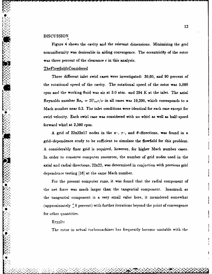
12
DISCUSSION
Figure 4 shows the cavity and the relevant dimensions. Minimizing the grid
nonuniformity was desireable in aiding convergence. The eccentricity of the rotor
was three percent of the clearance c in this analysis.
TheFlowfieldsConsidered
Three different inlet swirl cases were investigated: 30,60, and 90 percent of
the rotational speed of the cavity. The rotational speed of the rotor was 5,000
cpm and the working fluid was air at 3.0 atm. and 294 K at the inlet. The axial
Reynolds number Re, = 2Ui,,c/v in all cases was 19,200, which corresponds to a
Mach number near 0.2. The inlet conditions were identical for each case except for
swirl velocity. Each swirl case was considered with no whirl as well as half-speed
forward whirl at 2,500 cpm.
A grid of 22x22x17 nodes in the x-, r-, and 8-directions, was found in a
grid-dependence study to be sufficient to simulate the flowfield for this problem.
A considerably finer grid is required, however, for higher Mach number cases.
'- In order to conserve computer resources, the number of grid nodes, used in the
axial and radial directions, 22x22, was determined in conjuction with previous grid
dependence testing [16] at the same Mach number.
For the present computer runs, it was found that the radial component of
the net force was much larger than the tangential component. Inasmuch asthe tangential component is a very small value here, it meandered somewhat
' (approximately + 8 percent) with further iterations beyond the point of convergence
-- for other quantities.
ResultsThe rotor in actual turbomachines has frequently become unstable with the
%m% %
0%'
. •4•
. . ..0. . .. . . - - . - . .
13
shaft whirling.at a frequency approximately half of the rotational frequency. Results
for this important case of half-speed whirl are considered here. The net tangential
force acting on the eccentric whirling shaft is of considerable interest because it is
the driving force for the whirl phenomenon. In Figure 5 the effect of inlet swirl
strength on the net tangential force can be seen. The total net tangential force
contains contributions from both pressure and shear forces. As expected from the
literature, increasing swirl increases the driving force behind the rotordynamic whirl.
The contribution of shear forces to the total net tangential force is seen in
Figure 6. From the quantitative result in Figures 5 and 6 it is obvious that the
shear component of the net tangential force is less than one percent. The other 99
percent is from the net pressure force due to the circumferential pressure distribution
around the cavity. Observe that the south wall(cavity base) contribution is less than
* zero and the others are greater than zero. This gives a cancellation and a small
total shear force. Also, note that the south wall shear was the only one significantly
influenced by a change in inlet swirl.
While a positive tangential force is a whirl driving force, a negative radial force
is a restoring force. The effect of inlet swirl on the total net radial force can be seen
-' in Figure 7. The radial force generally decreases slightly with increasing swirl. It is
about four times larger than the tangential force. Note that the force is not restoring
the rotor to its original position, but is actually pushing it to larger eccentricities.
These same general trends were measured by Leong [17] at small eccentricities.
It was determined from Figures 7 and 8 that the net shear stress contribution
to the total net radial force is less than one percent, as is the case with the net
tangential force. Figure 8 also shows that all radial shear force components were
invariant with swirl, except at the south wall. As expected, the shear contribution

14
to the radial force there was a minimum when Wi*,, = 0.6 because this is near the
asymptotic value in which case there was negligible -re stress on the south wall.
Since the pressure force virtually determines the net forces acting on a seal, the
variation of pressure (relative to a reference of 306,000 Pa) in the circumferential
direction at two locations along the rotor are plotted. In Figure 9 the pressure
values are taken at the middle of the south wall of the cavity. Symmetry about
the axis through 0=180 degrees is observed indicating a very small contribution
to Ft, and swirl had little effect on this. In Figure 10 the pressure distribution
on the downstream tooth is given. Observe that here the pressure distribution is
not symmetric at all through this axis, contributing substantially to Ft. Higher
inlet swirl values produced this lack of symmetry, which caused an increase in the
tangential force.
The case of no whirl has also been studied previously. The current results for
the non-whirling case are very similar to those shown for half-speed whirl. This
was expected since for such small eccentricities the boundary conditions are nearly
the same.
.-. - The development of circumferential velocity within a bank of labyrinth cavities
has been of interest for some time because, as shown above, swirl has a substantial
influence on the forces generated by an eccentric seal. The circumferential variation
of swirl at the inlet and exit for the case of lowest inlet swirl is given in Figure 11.
The swirl increased in this case from the inlet to exit by about seven percent. This
• was expected since the inlet swirl was below the fully developed (i.e. asymptotic)
value. Notice that the peak of the distribution shifted circumferentially nearly 25
degrees. This is attributed to the eccentricity and swirl development. For the
-0 intermediate inlet swirl case of W* 0.6, the swirl velocity increased by four
" " . t4

'"' 15
percent. Since this value of inlet swirl is closer to the asymptotic limit, there was
less of an increase. The peak value shifted only about 12 degrees, in this instance.
For the largest inlet swirl case, the swirl changed little in magnitude and shifted
about 12 degrees.
The development of axial velocity through the cavity was also examined. This
* - development for all three inlet swirl cases is presented in Figure 12. In each case
the axial velocity inlet profile was exactly identical, and all three cases produced
S the same exit axial velocity. The exit axial velocity was almost symmetric about
an axis through 8 =180 degrees. For the present inlet Mach number, the velocity
increased by about two percent from inlet to exit.
The velocity, pressure, turbulence energy and turbulence dissipation distribu-
tions give additional insight into the flowfield within the cavity which is useful to
the developers of of simpler models. Reference [18] contains profile plots of these
quantities. These plots are for the intermediate inlet swirl case with half-speed
whirl. The velocity distributions within the cavity were quite similar to those pro-
duced by Rhode and Sobolik [14] for a concentric-rotor seal. The velocity did not
vary greatly circumferentially. This can be expected since the eccentricity was only
three percent. The axial velocity component shows significantly more circumferen-
tial variation than the other two velocity components.
Although they do not contribute significantly to the force components, shear
stress distributions are needed in the development of simpler models. Shear stresses
are plotted along each wall as well as the free shear layer for 8=0 in Reference
[111. The corresponding circumferential variation of these quantities at a location
midpoint along each surface is given here. Thus the two sets of figures together can
be used to approximate the entire three-dimensional shear stress distribution along
%'..

0
4.. 16
the cavity walls and the free shear layer.
The circumferential variation of the above shear stresses for a location midway
along each respective plane is shown in Figures 13 through 16. The 'reseg in
Figure 13 are for the midpoint along the south wall of the cavity. Stress r,z is
independent of inlet swirl and exhibits a minimum at 0=180 degrees due to the
..: lower axial velocity at that 0-location (most of the leakage flow is near 0=0). Stress
To was fairly invariant with 0, but swirl affected the magnitude of re as found in
the previous figures.
The shear stresses midway along the free shear layer are plotted in Figure
* 14. As with the corresponding south wall stresses in Figure 13, component ir is
independent of the inlet swirl and has a minimum at 0=180 degrees. Stress 're was
44.... very sinusoidal and decreasing inlet swirl increased the magnitude of the stress, as
expected.
The circumferential variation of east and west wall midpoint shear stresses can
be observed in Figures 15 and 16. For both walls r,, is again independent of inlet
swirl, and exhibits a minimum at 0=180 degrees. Stress 7-0 is nearly uniform with
theta and decreases with increasing inlet swirl.
CONCLUSIONS
* It has been shown that rotordynamic forces on an eccentric whirling labyrinth
A.,. seal can be calculated using this numerical approach. A qualitative comparison of
forces with Leong [17] gave good agreement. Although measurements of the rotor-
* dynamic forces on a single theeth-on-rotor cavity are not available for quantitative
comparisons, numerical simulations of multi-cavity domains in the near future will
allow this.
* The current computational results serve to provide the seal designer with
' 4.
% ^_r

17
more complete information about pressure circumferential variation within a cav-
ity. Specifically, the included results quantify the dependence of the tangential
and radial force components on the level of inlet swirl. For the cases considered
here, an i.:c:ease in inlet swirl re-distributed the pressure field to give an increased
tangential force and a decreased radial force. Further, the circumferential pres-
sure distributions presented reveal details concerning the large variation of those
force components with axial location from the mid-cavity location to that of the
downstream tooth.
It was further found that, while there is definitely a net fluid shear force acting
on the rotor, the combined effect of all stresses tend to cancel, giving less than a one
percent contribution to each force component. The circumferential variation of both
wall and "free" shear stresses is presented in order to allow the developers of simpler
flow models to refine their shear stress modeling. The same stress components are
quantified in reference [11] as a function of position along each surface at a fixed
e-location so that an approximate three-dimensional stress field can be constructed
from the two sets of stress data together.
...- A'"

18
ACKNOWLEDGEMENT
.:" The financial support of AFOSR is gratefully acknowledged.
5-
-
6?
6d
*
::7 .1,
19
REFERENCES
1 Alford, J. S., "Protecting Turbomachinery From Self-Excited Rotor Whirl,"
Transactions of ASME. Journal of Engineering for Power, vol. 87, pp. 333-344,
1965.
2 Kostyuk, A. G., "A Theoretical Analysis of the Aerodynaric Forces in the
Labyrinth Glands of Turbomachines," Teploenergetika, vol. 419(11), pp. 29-33,
1972.
3 Iwatsubo, T., "Evaluation of Instability Forces of Labyrinth Seals in Turbines
or Compressors," in Rotordynamic Instability Problems in High Performance
Turbomachinery, Texas A&M University, May 12-14 1980.
4 Iwatsubo, T., Matooka, N., and Kawai, R., "Flow Induced Force and Flow
Pattern of Labyrinth Seal," in Rotordynamic Instability Problems in High
Performance Turbomachinery, Texas A&M University, May 10-12 1982.
5 Childs, D. W., and Scharrer, J. K., "An Iwatsubo Based Solution for Labyrinth
Seals: A Comparison to Experimental Results," ASME Journal of Engineering
for Gas Turbines and Power, vol. 108, pp. 325-331, April 1986.
6 Childs, D. W., and Scharrer, J. K., "Experimental Rotordynamic Coefficient
Results for Teeth-On-Rotor and Teeth-On-Stator Labyrinth Gas Seals,"
in ASME 86-GT-12 at the 31st International Gas Turbine Conference and
Ezhibit, Dusseldorf, FRG, 1986.
-7 Dietzen. F. J., and Nordman, R., "Calculating Rotordynamic Coefficients of
Seals by Finite Difference Techniques," in Rotordynamic Instability Problems
in High Performance Turbomachinery. Texas A&M University, 1986.
20
8 Wyssman, H. R., "Flow In Labyrinth Seals And It's Influence On Rotor
Stability Of Turbocompressors," in Von Karman Institute Lecture Series 1987,
Von Karman Institute For Fluid Dynamics, Jan. 19-23, 1987.
9 Wyssman, H. R., Pham, T. C. and Jenny, R. J., "Prediction of Stiffness and
Damping Coeficients for Centrifugal Compressor Labyrinth Seals," in ASME
84-GT-86 at the 29th International Gas Turbine Conference and Ezhibit,
Amsterdam, June 4-7, 1984.
10 Tam, L. T., et al, "Numerical And Analytical Study Of Fluid Dynamic
Forces In Seals And Bearings," in ASME Biennial Conference on Mechanical
-,:,,Vibrations and Noise, Boston, 1987.
S11 Rhode, D. L., and Hensel, S. J., "Three Dimensional Computation Of Rotordy-
namic Force Distributions In A Labyrinth Seal," in ASME/AIAA/ASCE/SIAM,'APS
First National Fluid Dynamics Congress, Cincinnati, July 24-28, 1988.
12 Pope, S. B., "The Calculation of Turbulent Recirculating Flows ;n General Or-
thogonal Coordinates," Journal of Computational Physics, vol. 26, pp. 197-217,
*" . 1978.
- 13 Leonard, B. P., "A Stable and Accurate Convective Modelling Procedure Based
on Quadratic Upstream Interpolation," Computational Methods Appl. Mech.
Engr., vol. 19, pp. 59-98, 1979.
14 Rhode, D. L., and Sobolik, S. R., "Simulation Of Subsonic Flow Through
A Generic Labyrinth Seal," in ASME International Gas Turbine Conference,
Houston. Texas, 1985.
* ~ °• 15 Gosman, A. D. and Pun, W. M., "Calculation of Recirculating Flows," Research
S . - 5 - - .- S
21
Report, Report no. HTS/74/2, Dept. of Mech. Eng., Imperial College, London,
England, 1974.
16 Rhode, D. L. and Nail, G. H., "Computation Of Cavity-BY-Cavity Flow
Development In Generic Labyrinth Seals," in ASME International Computera
In Engineering Conference, San Francisco, July 31 - Aug. 3, 1988.
17 Leong, Y.M.M.S., "Experimental Forces Induced by Flow Through Model
* Labyrinth Glands," Research Report, Ph.D. Dissertation, Heriot-Watt Univer-
sity, Edinburgh, June 1983.
18 Hensel, S. J., "Calculation of Rotordynamic Forces On Labyrinth Seals,"
Research Report, M.S. Thesis, Texas A&M University, College Station, Texas,
1986.
.
.,
-
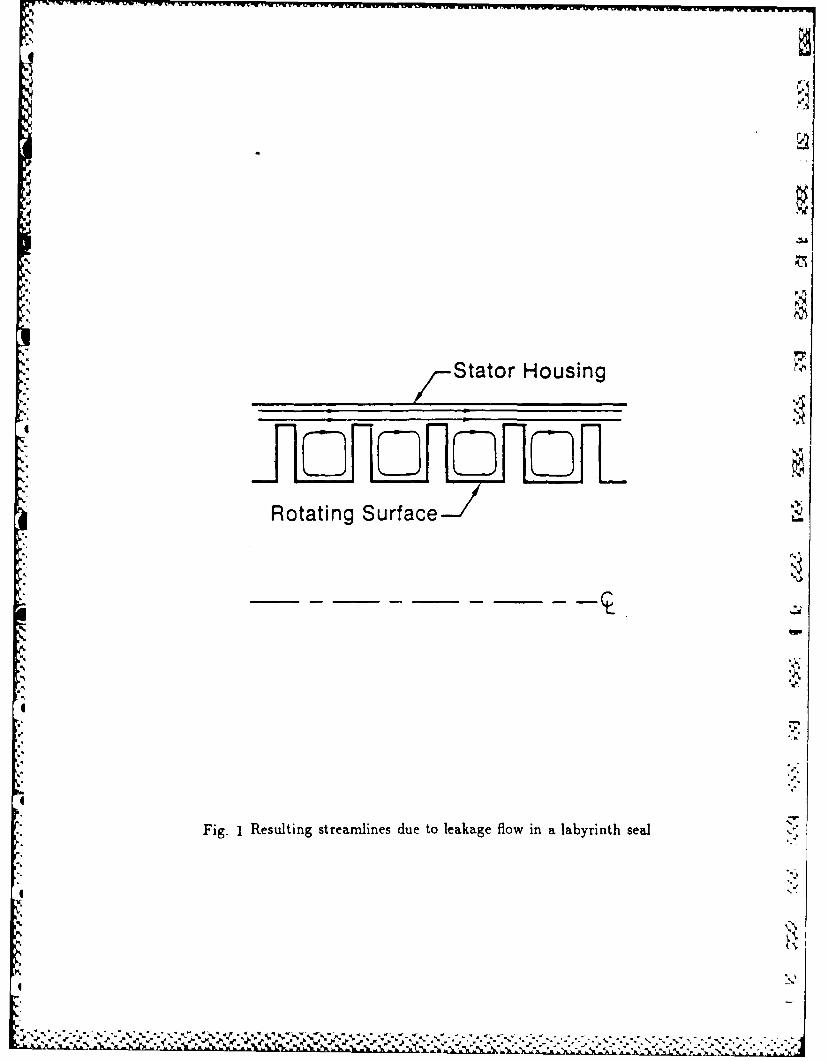
'
mr
Stator Housing
Rotating Surface
f".
II
Fig. 1 Resulting streamlines due to leakage flow in a labyrinth seal
.1
I'
,
,

a.%
Fig. 2 An example of a finite differencegrid in the eccentric region of the seal
. . . .

IONN
* ON
WW W P =E
SS
Fig. 3 Three-point interpolation for the westface of the control volume on a uniform grid using QUICK
S
-0 -
'odA- .".J .S .-
'_," ' ,,, . ,...,", '," . . ' e. ' '., ".. "... .. .,>"i .. ,.,, " ," ,."'," ."., .","''"'"• .'' ".

.I ,- 4.95mm
0.4953 m mTIM•
1.981mm
H-I 3.962 mm
39.6 mm
Fs
~Fig. 4 The seal cavity investigated and its dimensions

13.0
! 11.0
.9.0
-7.0
5 .0 I.
0. J0. 0.3 0.5 0.7 0.9
W
aw
Fig. 5 Effect of inlet swirl on thetotal tangential force for half-speed whirl
............................................

- 2.0
-2.00
1.5* EAST-1.75
~1 0SOUTH -1.50
0-50
WEST-1.25
TOTALI -1.0
-0.5 0.0.0.3 0.5 0.7 0.9
wa w
Fig. 6 Effect of inlet swirl on the shear stress contribution tothe total tangential force on the cavity walls for half-speed whirl

el
3.8
~3.6
%-3.4
0.*0. 0.3 0.5 0.7 0.9V aw
Fig. 7. Effect of inlet swirl on the[.;. total radial force for half-speed whirl
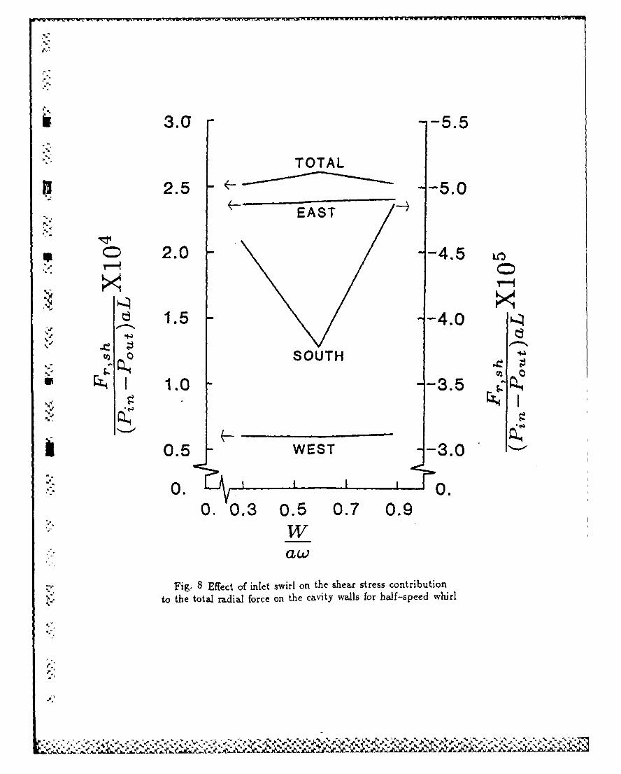
3.0 -- 5.5
TOTAL
2.5 -- 5.0
EAST
2.0 --4.5
1.5 --4.0
SOUTH
*1.0 -- 3.5
0.5 WEST -- 3.0
:-4 0. 0.0. 0.3 0.5 0.7 0.9
Waw
Fig. 8 Effect of inlet swirl on the shear stress contributionto the total radial force on the cavity walls for half-speed whirl
%',
.1'
S.'S,**,
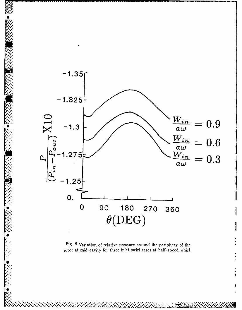
h0.9
-1.35-
g4d.
:.z- 1.350.
- -- 0.6
aw =0.3aw
=] -25
0.o 0 90 180 270 360
,(DEG)
Fig. 9 Variation of relative pressure around the periphery of the" - rotor at mid-cavity for three inlet swirl cases at half-speed whirl
0%
6.

' \
-5.05-
v-I -5.0
-4.95- -a 0.9aw
---- Winl - 0.6aw
-4.9 _ W in 0.3aw
0 90 180 270 360
O(DEG)
K -- Fig. 10 Variation of relative pressure around the periphery of
the downstream tooth for three inlet swirl cases at half-speed whirl
-
,-.. ..: ....... . r-... ..... ...... .,. ... ... :........... . -...,. ,. ...... :.. .. -. ,... . ...:.* a , .- :.....-.
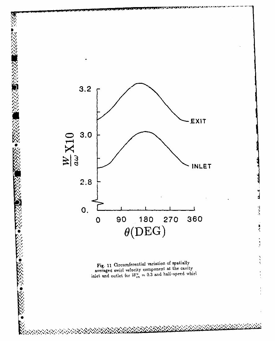
3.2
-EXIT
S3.0
INLET
0 90 180 270 360
O(DEG)
Figi Circumferential vraino ptal
averaged swirl velocity component at the cavity
inlet and outlet for V 0.3 and half-speedl whirl
"~ %?
S.
'S
:'S.
5--.. l> 1-

1.03 EXIT
1.02 I1.01 I
IN E
1.00 -
0.99k
0. 0 90 180 270 360
~O(DEG)
Fig. 12 Circumferential variation of spatially averaged
axial velocity component at the cavity inlet and outlet for allthree inlet swirl cases (TV, = 0.3,0.6, and 0.9) at half-speed whirl
i" Ii
N' ii

1 -11.0h -1.56
-1.540
7.0-1.52-
*B.5.0
s a t s AtBi C c3 .0 e
0O1
i -1.46
" -''.-.0 90 180 270 360.-- O(DEG)
€< Fig. 13 Circumferential variation of rotor surface'" shear stresses at mnid-cavity for cases A,B, and C
. (,Vi*, =0.3,0.6, and 0.9 respectively) at half-speed whirl

-- 2.03 3.45
3.4 B
-14
-0.5g
0.0 90 180 270 360
9(DEG)
Fig. 14 Circumferential variation of free shear layershear stresses at mnid-cavity for cases A,B, and C
(Wi*A =0.3,0.6, and 0.9 respectively) at half-speed whirl
CC.~ tk%

1.86
AA
1.84 -,,,,.- -1.0
1.82-0.8
. 1.80 N_-0.6
CL 1.78v°- -0.4
LLI
- 1.76 A,B,Cr..:, j -0.2
C
0. *0.0 90 180 270 360
-(DEG)
* Fig. 15 Circumferential variation of tooth shear stressesat the midpoint along the downstream tooth for cases A,B and C
- (1V,, =0.3,0.6, and 0.9 respectively) at half-speed whirl
S.-.
0?:-a'
pa°
C. -
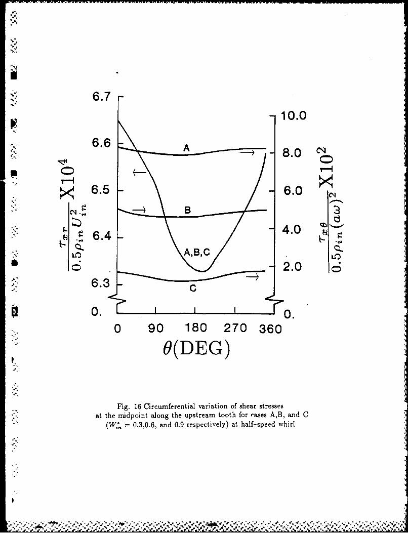
6.7- 10.0
6.6 A,A - 8.0
6.5 6.0 C9
4 6.4AAL
*6 2.0 6"..
oo0. 0o.
0 90 180 270 360
I9(DEG)
Fig. 16 Circumferential variation of shear stressesat the midpoint along the upstream tooth for cases A,B, and C
(W, = 0.3,0.6, and 0.9 respectively) at half-speed whirl
• °I

iIN
COMPUITATION OF CAVITY-BY-CAVITY FLOWDEVELOPMENT IN GENERIC LABYRINTH SEALS
D.L. Rhode- and G.H. Nail*-cTurbomachinery LaboratoriesMechanical Engineering Dept.
Texas A&M UniversityCollege Station, TX 77843
Associate Professor-~Graduate Student
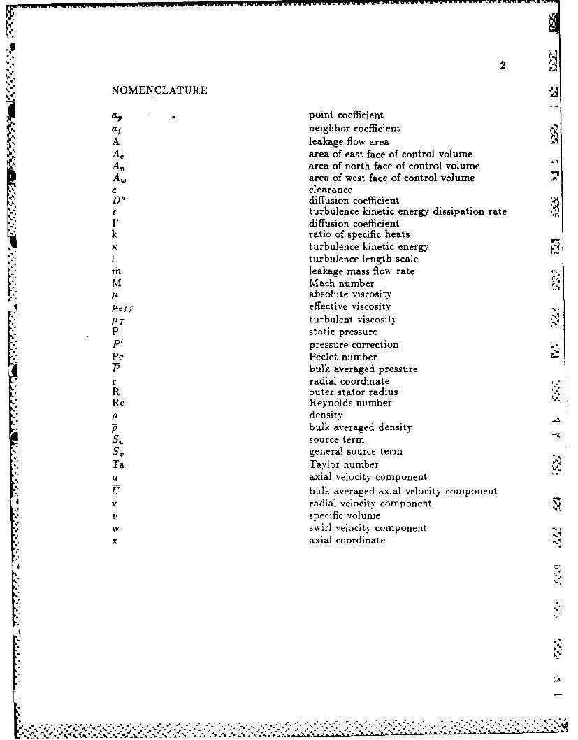
2
NOMENCLATURE
•a, point coefficientaj neighbor coefficientA leakage flow areaAe area of east face of control volumeA,, area of north face of control volumeA, area of west face of control volumec clearanceDu diffusion coefficient
.5 f turbulence kinetic energy dissipation rater diffusion coefficientk ratio of specific heatsr. turbulence kinetic energy1 turbulence length scalern leakage mass flow rate ,.M Mach numberp absolute viscosity
* 1-eff effective viscosityP T turbulent viscosityP static pressureP' pressure correctionPe Peclet numberP bulk averaged pressurer radial coordinateR outer stator radiusRe Reynolds numberp density
bulk averaged densitySu source term
' general source termTa Taylor numberu axial velocity componentU bulk averaged axial velocity component
4 v radial velocity componentv specific volumew swirl velocity component 'Nx axial coordinate %I
-..
% " ' . .. ' " S5
S' , -. . - - -. . - "z -'- S. . " Z . " . -. * . . '. '. .-. *. " -" . . % "

3
Subscriptsueb i cavity exit, east face of control volume
E eastern neighbor control volumeEE eastern neighbor of eastern neighbor
cavity inletn north face of control volumeN northern neighbor control volumeNN northern neighbor of northern neighbor
S P center control volumep center of control volume-. general flow variabler radials south face of control volumeS southern neighbor control volumeSS southern neighbor of southern neighborsh shaft0 circumferentialw west face of control volume
%: W western neighbor control volumeWW western neighbor of the western neighborx axial
Superscriptsnondimensionalized, uncorrected value
* I correction value
5
............. !-.
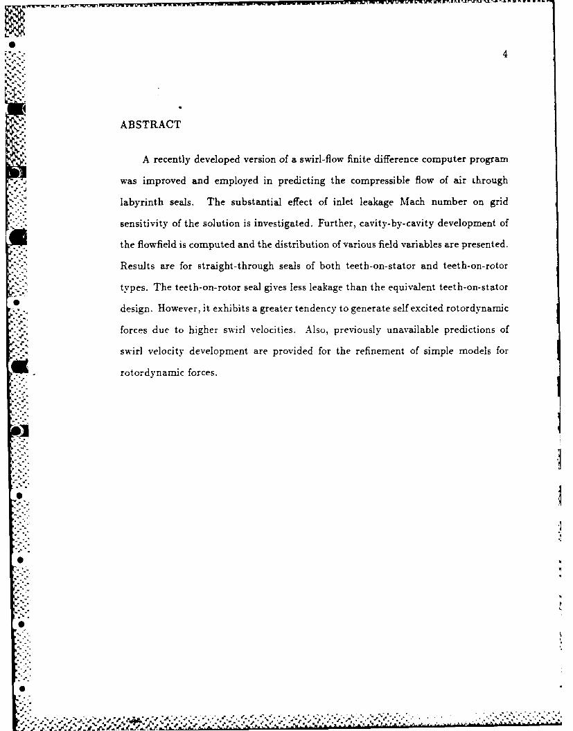
4
WI..
ABSTRACT
A recently developed version of a swirl-flow finite difference computer program
was improved and employed in predicting the compressible flow of air through
labyrinth seals. The substantial effect of inlet leakage Mach number on grid
sensitivity of the solution is investigated. Further, cavity-by-cavity development of
the flowfield is computed and the distribution of various field variables are presented.
Results are for straight-through seals of both teeth-on-stator and teeth-on-rotor
types. The teeth-on-rotor seal gives less leakage than the equivalent teeth-on-stator
S ,,design. However, it exhibits a greater tendency to generate self excited rotordynamic
forces due to higher swirl velocities. Also, previously unavailable predictions of
swirl velocity development are provided for the refinement of simple models for
S rotordynamic forces.
-° 1*-i
*i
04
,6::

5
INTRODUCTION
Labyrinth seals are most commonly used in rotating machinery such as pumps,
compressors and turbines. C. A. Parsons [1] apparently was the first to introduce
the labyrinth seal in his development of the steam turbine near the turn of the
century. Figure 1 shows a straight-through, teeth-on-rotor labyrinth seal.
The sealing objective is to present a highly frictional flow path between high-
and low-pressure regions by means of a series of non-contacting restrictors and
separating chambers. When the fluid enters a seal, it flows through a small
constriction at the first tooth and part of the pressure head is converted into mean
flow kinetic energy. Seals are designed so that a large portion of this kinetic energy
is lost via turbulence dissipation in the chamber immediately downstream. Other
constrictions and chambers follow downstream, where the process is repeated.
Numerous investigators have proposed empirically based relations utilizing
characteristics of the overall flowfield for estimating the leakage rate. Experimental
data such as total pressure drop has been recorded and used to develop these
relationships. Leakage has been expressed as a function of overall pressure drop,
friction factor, seal clearance, tooth thickness, cavity width, shaft speed and number
of teeth. Resulting predictions from these formulas are successful when applied to
seals which are very similar to those which were empirically studied. However,
any significant difference in seal geometry can give considerable error. Therefore,
a more widely applicable method has been sought for seals of arbitrary geometry,
shaft speed, pressure drop, etc.
A numerical algorithm for solving the Navier-Stokes equations is widely apph-
cable for seals. Furthermore, such a computational tool does not require extensive
empirical data as a user input. However, this approach and can be quite expensive.
rAe

I-
1f-Stator Housing
Rotating Surface Z/
Fig. 1 Basic configuration and expected streamline
pattern for a generic straight- through labyrinth seal

7
Stoff's investigation [2] of incompressible flow in seals was the first attempt at such
a numerical polution. His work involved an extension of the TEACH computer pro-
pram [3], which constitutes the basic approach used in this study also. Some of the
more recent numerical results are those of Rhode and Sobolik [4] and Sobolik [5]
involving subsonic compressible flow. The current study builds upon that work.
The primary objective of the present research is to predict the flowfield
-. development from cavity to cavity along a labyrinth seal. Secondary objectives
include comparison of swirl velocity and other quantities for corresponding teeth-
on-stator and teeth-on-rotor generic labyrinth seals. The computer code of Sobolik
[51 was extended in various ways in order to achieve these objectives.
Wi
N~

8
PREVIOUS WORK
Most of the leakage oriented research has been aimed at developing simple
empirical relationships between the leakage flow rate and the overall pressure drop,
seal geometry, shaft speed and Reynolds number. Details such as velocity profiles
have only very recently become the objective of experimental researchers.
Work done on labyrinth seals can be classified into compressible fluid leakage,
incompressible fluid leakage and rotordyamic instability studies. The paper by
Sneck [61 and the theses by Cogan [7] and Sobilik [5] were invaluable in compiling
this review. The topic of instability is not addressed in this paper, and thus related
studies are not included.
Compressible Fluid Leakage Studies
Martin [8], Stodola [9], Gercke [10], Egli [11], Dolin and Brown [12], Hodkinson
1[3J, Kearton and Keh [14], Zabriskie and Sternlicht [151, Vermes [16], Rao and
Narayanamurthi [17], Deich, et al. [18] and Benvenuti [19] are examples of early
work with compressible flow seals. These studies drew conclusions based on gross
overall characteristics of the flowfield. These researchers made assumptions such as
constant flow area, uniform axial velocity profile or negligible turbulent kinetic
energy carry-over. These assumptions greatly simplify the problem. However,
models developed in this way have been very limited in application.
The first to take detailed measurements of compressible flow in labyrinth seals
was Hauck [20]. He measured the axial and swirl components of velocity in straight-
* through and stepped seals. Velocity profiles were measured both in the cavity as
well as in the leakage region. Hauck's test facility operated at both 4000 and 5000
CPM, and allowed for rotor eccentricity up to 75 percent of the clearance for aS.'
*t

9
concentric rotor.
Appare.tly the first to present a detailed numerical solution for the compress-
ible flowfield within a labyrinth seal were Rhode and Sobolik [4]. A finite difference.
method was used employing Patankar's [21] SIMPLE (Semi-Implicit Method for
Pressure-Linked Equations) algorithm. Converged solutions were obtained using
each of two different finite differencing schemes: the Hybrid scheme developed by
Spalding [221, and the QUICK scheme developed by Leonard [23]. Zimmermann
and Wolff [24] developed an analytical model for correlation of leakage and pressure-
drop. Previously obtained numerical solutions were used to integrate cavity exit
velocity profiles and compute standard loss coefficients for each cavity.
Kirk [25] developed a relatively simple computer program to calculate the
circumferential swirl and pressure distribution. He computed a nondimensionalized
tangential velocity ratio and compared with previously obtained experimental
results. The experimental data reveals a reduction of swirl, as the flow moves
radially inward, that was not predicted. However, predicted and experimental
results for swirl never differed by more than 25 percent.
Nordmann, et al. [26] also used a finite difference program to simulate flow in
straight-through labyrinth seals. The effort was directed toward the fluid forces and
rotordvnamic coefficients. But they also plotted leakage as a function of pressure
ratio, comparing against previous obtained experimentally results.
Incompressible Fluid Leakage Studies
Jerie [271, Bell and Bergelin [28], Nikitin and Ipatov [29] and Han [30]
are examples of earlier studies dealing with gross overall characteristics. The
conclusions reached by these researchers developed the application of flow and
velocity carry-over coefficients. critical Reynolds number for transition to turbulence
%

10
and friction "oefficients.
Three recent studies constitute the first investigations pertaining to detailed
characteristics of velocity and pressure throughout a seal cavity. One was conducted
by Stoff [2]. He used a finite difference computer program descended from the
kTEACH program to solve the Reynolds-averaged Navier-Stokes equations along
with those of the tK - f turbulence model. Predictions as well as experimental
measurements of water in a large scale straight-through seal facility were obtained.
He compared predictions of a single radial profile of mean swirl velocity and rms
swirl velocity with corresponding experimental measurements for an axial station
midway between adjacent teeth.
Rhode. et al. [31] is the second detailed study. That paper reports comparison
predictions of two cavity configurations for a straight-through seal. A more recent
version of a swirl-flow finite difference computer program, also descended from
TEACH, was employed. Detailed radial profiles of the three velocity components,
pressure and turbulence kinetic energy were shown. In addition, a recent convective
differencing scheme was evaluated for numerical stability and accuracy.
Finally, Demko [32-34] conducted a study using both computational and ex-
perimental methods. He presented corresponding predictions and measurements of
selected quantities such as axial and radial velocity and pressure. By investigating
flow at relatively high Taylor numbers (typically Ta> 10') he was able to con-
putationally and experimentally verify the existence of a double recirculation zone
pattern. He presented his results in the form of a flow map which one can use to
predict the existence of either a single versus a double recirculation zone within the
cavity.
[.1
-,*- ' -' . , .,-- . .- ,..- .. , . . . . . .. . . . . ..

11
COMPUTATIONAL APPROACH
General Methodology
The compressible flow program for flow in labyrinth seals is a descendant of the
TEACH program [3]. Seven simultaneous, partial differential equations are solved.
These are: (a) the compressible, axisymmetric form of the Reynolds-averaged
equations for conservation of momentum (with x, r, and 0 time-mean velocity
components u, v, w), (b) the two turbulence transport equations constituting the
K - E turbulence model, (c) the energy equation, and (d) a pressure equation which
determines the pressure field and enforces conservation of mass. Each of these can
be divided into convection, diffusion and source term components and cast in the
general form
-(Pu') + - (pvrd6)
49 ax Ora- .(F =) (1)
Phi is the general dependent variable and 170 is the diffusive coefficient
*. -respective to each equation. For example, in the x-momentum equation 6 = u
and F = L ff. The effects of turbulence are incorporated through modification of
the laminar-flow momentum diffusion coefficient u. The turbulent viscosity pT is
added to p giving an effective viscosity /1 ff which is given by
A eff I'T " '1 (2)
The two-equation K - E model r351 was utilized to evaluate PT.
.....'- ..-......-'."--...-.--..-...-..-...............-............-.'..--.....-..-........-.....-...-'.-..-....--..'..-..-""..-..-....."-.--.-....

12
Figure 2 shows the staggered grid system on which the finite difference
equations axe solved. Values for all variables except u and v are stored at the
intersections of the illustrated grid lines, such as point P. The axial and radial
velocity components are stored at locations denoted by arrows. Different control
volumes C, U and V for the variables stored at the p, w and s locations are shown
in Fig. 2. An example of the computational domain that has been chosen for a
labyrinth seal can be seen in Fig. 3.
Each 4 has a corresponding finite-difference equation which was obtained from
Eqn. 1 by applying the Gauss Divergence Theorem and expressing the result
in terms of neighboring grid point values. The incorporation of the differencing
schemes is discussed in Rhode, et al. 131j. As an example, the axial momentum
equation from which u*, a velocity estimate, is computed is
u; = u A+ - sP + Su(3)
To satisfy conservation of mass locally, the values for u* and v* must undergo a
correction. This correction is accomplished using the pressure-correction P' values.
The equation for this quantity is derived from conservation of mass and momentum
and is explained in further detail in a subsequent section. The expression for the
corrected axial velocity formulation is
U ; + Du(P- P) (4)
The radial velocity is corrected similarly. The P' equation takes the form
0,
.4
S:', , - ." .""--'-% -, . .2% "% """% "% . "% % """", """"" ' . % - - - '% % -" "' ° % ' "% '%.''

13
ObO
0 0d
0. bobo
LL o
-. j
0<
0
0<
W 0 c
A*L ..- .-

14
1 1 23... NI
IN OUT
r"
41 1 1e" w !!1- _- _
x,u
Fig. 3 Computational domain for a labyrinth sealcavity showing a uniform coarse grid
'S..
.5.%
r +)

15
4P"=Za aP + S (5)
as discussed in Patankar [21].
For the previously considered incompressible flow cases [31], the flow could
be considered streamwise periodic. Thus, cavity inlet boundary conditions for all
variables excepting pressure were set equal to the newly calculated exit values at
the conclusion of each iteration. Flow at the cavity outlet is strongly convective in
nature, and thus the upwind differencing used there requires no outlet boundary
conditions. For the present compressible flow grid independence cases, the inlet
-: values resulting from the above procedure were adopted in dimensionless form.
Alternately, the cavity-by-cavity development computations used the exit values
from the previous successive cavity as the corresponding inlet values. Further, the
empirically-based law of the wall was used to evaluate normal derivatives of velocity
- tangent to a given wall.
False Diffusion
The upwind differencing scheme has been used extensively, however, it can
introduce false diffusion. rPhis truncation error occurs predominantly ii. flows where
convection domiunates (i.e., where the grid Peclet number iPe! Il exceeds 2.0)with substantial streamline-to-grid skewness and substantial diffusion normal to the
streamlines.
False diffusion can cause an overly diffusive solution. Recirculating flows are
particularly susceptible to the effects of false diffusion because of the certainty
of considerable velocity gradients and streamline-to-grid skewness. Th. QUICK
(Quadratic Upstream Interpolation for Convective Kinematics) scheme of Leonard
.N
..... ... ... .. .. ... . . .--....-..-.... . . . *. ..-. , ,- ,-.N . ,...,> .N .. ...- - ,;.-.. ,_, .

16
[23] was derived with the intention of reducing false diffusion. It employs a three-
rpoint, upwind-shifted interpolation formula. Predictions for turbulent flows by
Leschziner and Rodi [36] and Han et al. [37] have indicated distinct advantages over
,. the Hybrid upwind/central differencing scheme. Moreover, comparisons between
the Hybrid and QUICK .,hemes for incompressible flow in labyzitih seal cavities
by Rhode, et al. [31] for example, showed that the QUICK scheme yielded grid-
independent solutions on considerably coarser grids than for the Hybrid scheme.
aL QUICK has been used in formulating the convective terms of the momentum
equations only. Leschziner and Rodi [361 showed the r and e solutions are not
significantly affected by alternative differencing schemes because of the source-term
dominance of the corresponding transport equations. The . and c source terms
contain the large generation and dissipation effects.
Computational Devolopments
An improved version of the compressible-flow P' equation was developed and
tested. The essence of the modifications are best understood after reviewing a
., derivation of the P' equation for a simple case of one-dimensional axial flow. The
' derivation begins with the discretized form of the steady flow mass conservation
equation
' - (P =)w 0 (6)9.
* Lower case subscripts refer to values at control volume faces. A typical control
*.- volume for P' is shown in Fig. 2 as the C control volume. The mass flux through
* '- the east face. for example, where the p'u, term has been neglected is
6
* °-
-.. - * -. '*o.~* ,* * .
,..'. .. . . . . . .

17
i(PU)e = (p " + P'),.(U + U') = p:u: + pU, + p'u, (7)
The quantities p* and u" are the latest estimates to be corrected via p' and u' in
order to satisfy the mass conservation equation.
The previous version of the program used a formulation for the p' terms using
the ideal gas equation of state which gives
.e 1 ,j , + P) 8e2(= pE P) 2(RTE RTp
Note that the expression for p,, in Eqn. 8 is the simple arithmetic mean. It
was found in the present study that expressing P' in this way contributed to
numerical instabilities during the iterative solution algorithm. This effect was more
pronounced when the grid lines were non-uniformly distributed within the flow
idomain. An alternative formulation of pC that reduced numerical instabilities when
using non-uniform grids was sought. Several variations were numerically tested for
a labyrinth cavity flowfield. Evaluation of p directly from the ideal gas equation of
state without using a p' quantity was an improvement over the p = p !-p' approach.
This led to an algorithm that is less susceptible to numerical instabilities. The
expression replacing Eqn. 7 is
(PL)e pU( + u')C PeUe + Pe 'e (9)
here p, is formulated using the harmonic mean expression
2 ppPE ,PC = (0l)PP PE
- .!

18
- From the axial momentum equation, one finds the following expressions [21]
for velocity corrections
Ue D'Pp' P )(11)
Du- Ae
ap
'Upon appropriate east and west face mass flux substitutions into Eqn. 6 the
following difference equation is obtained for P
[AE + Au1P = AEPE' +~ AwPir Arhn (12)
AE p,,,Du,
Ar*= pw - peu:
The P equation used in the current computer program was derived from the
two-dimensional flow mass conservation equation in cylindrical coordinates. The
NOl

19
procedure exactly parallels th.t given here. Appropriately, P= 0 along boundaries
was utilized for boundary conditions.
The TDMA (Tri-Diagonal Matrix Algorithm) is used to solve for the dependent
variable of each finite difference equation in a line-by-line fashion. The previous
version of the code solved for one vertical column at a time, beginning at the west
boundary and sweeping line-by-line to the east boundary. This procedure causes
the inlet boundary condition, usually at the west boundary, to be felt quickly by
interior points of the calculation domain. This desirable effect is greatly enhanced
if the fluid flow is in the same direction as the line-by-line sweeping motion of the
TDMA.
The previous method of solving for vertical columns while sweeping from west
to east tends to work very well in the predominantly straight-through west to
east leakage flow region. It does not, however, efficiently incorporate the effect
of boundary conditions within the recirculation zone of the cavity. For this reason
an ADI sweeping procedure was implemented. It alternates between west-east and
north-south sweeps, solving for vertical columns and horizontal rows, respectively.
In this way, information from the boundary conditions is efficiently transmitted to
all regions of the flow domain.
%
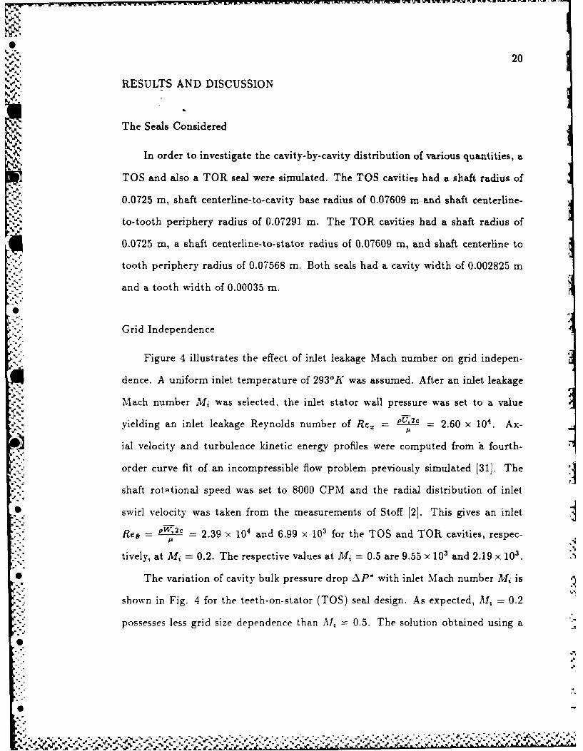
20
RESULTS AND DISCUSSION
The Seals Considered
In order to investigate the cavity-by-cavity distribution of various quantities, a
TOS and also a TOR seal were simulated. The TOS cavities had a shaft radius of
0.0725 m, shaft centerline-to-cavity base radius of 0.07609 m and shaft centerline-
to-tooth periphery radius of 0.07291 m. The TOR cavities had a shaft radius of
0.0725 m, a shaft centerline-to-stator radius of 0.07609 m, and shaft centerline to
tooth periphery radius of 0.07568 m. Both seals had a cavity width of 0.002825 m
and a tooth width of 0.00035 m.
" - ." Grid Independence
Figure 4 illustrates the effect of inlet leakage Mach number on grid indepen-
dence. A uniform inlet temperature of 293°K was assumed. After an inlet leakage
Mach number Mi was selected, the inlet stator wall pressure was set to a value
yielding an inlet leakage Reynolds number of Re, = PU, = 2.60 x 10⁴. Ax-
ial velocity and turbulence kinetic energy profiles were computed from a fourth-
order curve fit of an incompressible flow problem previously simulated [31]. The
shaft rotational speed was set to 8000 CPM and the radial distribution of inlet
swirl velocity was taken from the measurements of Stoff [2]. This gives an inlet
Reg = 2.39 x and 6.99 x 10' for the TOS and TOR cavities, respec-
tively, at Mi = 0.2. The respective values at Mi = 0.5 are 9.55 x 10³ and 2.19 x 10³.
" The variation of cavity bulk pressure drop AP* with inlet Mach number Mi is
shown in Fig. 4 for the teeth-on-stator (TOS) seal design. As expected, Ali 0.2
possesses less grid size dependence than 1i = 0.5. The solution obtained using a
Sii
*'f ,€ , -. ¢"-r-. -. , €, """""" " - "" '

21
35x45 (x and r direction) grid is essentially grid independent near Mi= 0.2. The
change in 4,P" at Mi = 0.2 was approximately five percent in changing from the
20x30 to the 35x45 grid. This will be substantially less for a similar comparison
using 35x45 and 50x60 grids. Observe the increased dependency on grid spacing at
Mi = 0.5. This is attributed to the much higher pressure gradients, and in turn,
density gradients at the higher Mach numbers.
Almost identical behavior was found for the teeth-on-rotor (TOR) design,
which is not shown here. However, the value from the 65x75 grid at Mi = 0.5
for the TOR design is 0.474, whereas the corresponding value for the TOS design
is 0.429. This indicates that the TOR design provides around 10.5 percent greater
flow resistance. Stated differently, for a given AP*, the TOR seal is expected to
give less leakage. This agrees with a corresponding experimental comparison where
both seals contained fifteen cavities of the present design.
Figure 5 shows the streamline pattern in a TOS generic labyrinth seal for
Al, = 0.5. It is similar to that for incompressible flow in a similar generic seal
in the paper by Rhode et al. [313. The reattachment stagnation point in close
.* proximity to the high speed leakage flow region gives rise to large velocity gradients
just upstream of the downstream tooth.
Cavity-by-Cavity Flowfield Development
The following results were obtained by utilizing the finit- difference code to
simulate the flowfield development through a labyrinth seal, one cavity at a time.
Figure 1 illustrates the cavity numbering scheme which is utilized in the following
discussion. At the inlet to the first cavity a leakage Mach number of 0.3 was
assumed. A uniform temperature profile of 300'K was used as well as a uniform
.W•~~-N* *--- *' - ~ *w '

22
0.6- O-20x30o - 35x 45
0.- A- 50x 600.5 c-65x 75
0.4-1! 0-AP 0.3-
0.2-
Ok. 0.1-
0.0 I
0.0 0.1 0.2 0.3 0.4 0.5 0.6* M1
* Fig. 4 Dimensionless pressure drop AP' atAl 0.2 and 0.5 for different grids, TOS
r , r lS W r
... **..~. ~* - ~w~.%

23
x/L
03. .2 .4 .6 .8 t.
1 . I I,
.99
. 985
.98
r/R 1.65
.975
.97irl 1.3
*.96S
qG 1.0
0.0
Fig. 5 Dimensionless streamline pattern atA1 0.5 for TOS
-. . V
. . . . * * ~ * * * * * ~ ~ * . . ."-g-A, ~ p .

24
axial velocity profile. The inlet radial component. of velocity was assumed to be
zero. An inlet axial leakage Reynolds number of 32,000 was assumed. A uniform
inlet profile of turbulence kinetic energy was used and a value of 3 percent of the
mean flow kinetic energy was specified. The shaft speed was set to 9500 RPM.
Results were obtained using two different values of non-dimensional bulk swirl
u1 velocity W " for comparison. The TOS cases were run at 147. of 0.0 and 0.58, while
the TOR cases had 1497 of 0.0 and 0.49. These non-zero inlet swirl cases give an
Reo of 1.29 x 10⁵ and 1.14 x 10s , respectively. These values of W were selected as
estimates of the inlet swirl resulting from rotating machinery upstream of the seal.
,".> After obtaining a converged solution for the first cavity, the field variable values
at the cavity exit plane are used as inlet values for the next cavity. Thus it was
possible to simulate the flow development along the labyrinth seal by approximating
inlet conditions for the first cavity and then proceeding downstream one cavity at
a time.
For the TOS case of zero inlet swirl, Fig. 6 shows the increase of Wj* with an
almost constant slope. This result will be useful to the developers of simple flow
models for calculating the net rotordynamic force which arises when the rotor is
eccentric with respect to the housing. It is particularly noteworthy in this regard
that the calculation of correct rotordynamic forces is sensitive to the correctly
simulated distribution of TW° . Further there are no previous measurements or
predictions of this distribution so that the developers of simple models have been
unable to verify this aspect of their modeling. Thus it is significant that Fig. 6
shows a slow rate of growth of 11'. In fact, such generic TOS seals with as many
as fifteen cavities never even approach the asymptotic value which is expected to
be slightly less than 0.5. Figure 7 shows a linear decrease for the TOS case of
S.'
:..,[.
* .2 ,.., ' ""'L -. ,., '; -. : . . ',.. -'.,.,r''- :'- .? ." .. . " ."' r" """ . " r" " "" " " ' " " " " " . .
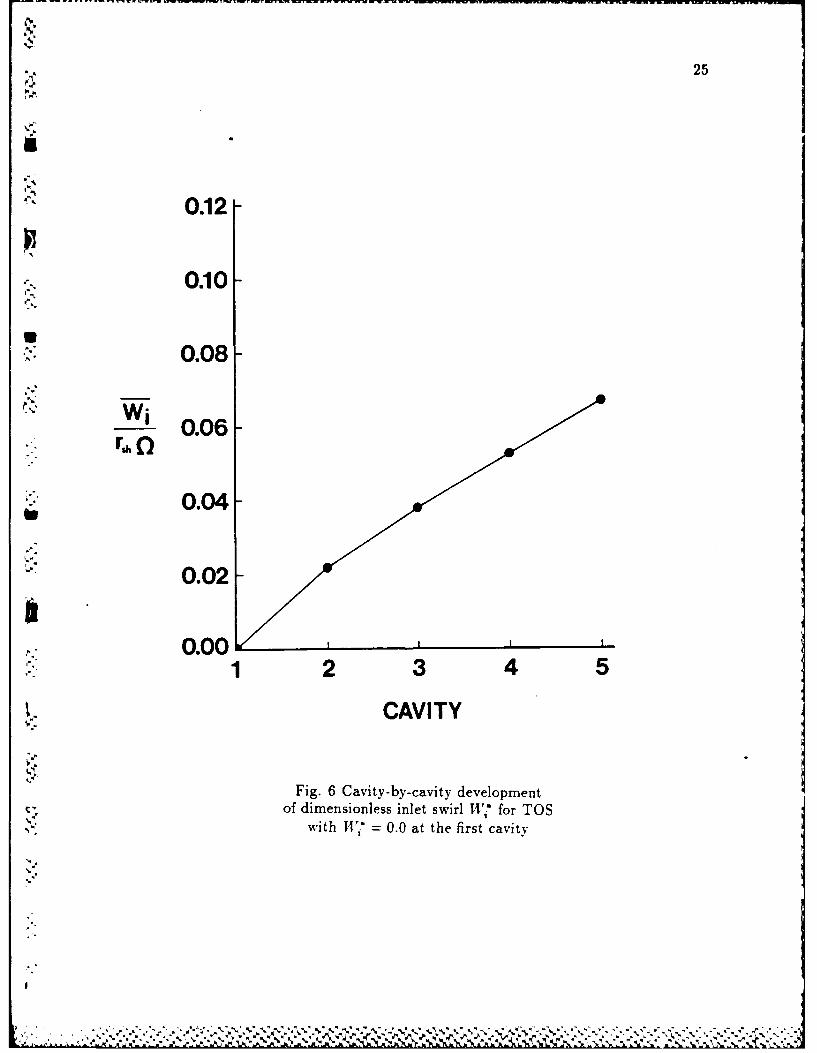
25
0.12
10.10
0.08
Wi 0.06-
b 0.04
0.02-
0.001 2 3 4 5
CAVITY
Fig. 6 Cavity-by-cavity developmentof dimensionless inlet swirl 147 for TOS
with 1 = 0.0 at the first cavity
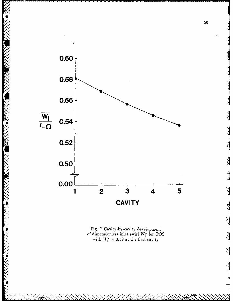
26
.,.-
0.60
0.58
, 0.56
0-52
* 0.54
0.50
0.001 2 3 4 5
CAVITY
* Fig. 7 Cavity-by-cavity development%: of dimensionless inlet swirl W* for TOS
with 7 = 0.58 at the first cavity
.
"' ....S.-: J . . .i ~ A ~ qj5l-
,'5 .e " . .. " . . " . . " ' , % ' ' o °%- * . . . . . . % . . % % " % ' • " . - . - " % . . - . , - % • - , , -.- j = =

.WW1
27
"4i*= 0.58 and thus indicates an asymptotic value for 'i * which is slightly less
"' than 0.5.
The distributions shown in Figs. 8 t'.'ough 10 reveal changes in the field
", variables as the flow proceeds cavity- by- cavity downstream. The axial velocity
distributions of Fig. 8 indicate that this quantity has become essentially streamwise
periodic within the third cavity. Even though Figs. 6 and 7 showed an almost linear
development of Wj , the detailed distributions in Fig. 9 show a significantly non-
linear rate of increase within the recirculation zone in the cavity region. The large
,.p. turbulent shear stress roe on the shaft gives rise to the shape of each radial profile
near the shaft. Finally, Fig. 10 shows the effect of radial turbulent diffusion on
turbulence energy development in the leakage region. This is most clearly shown
for the developing profile in the first cavity. Although not shown here, the radial
velocity profiles showed very little change.
The leakage Mach number increased from a value of 0.30 at the inlet of the
first cavity to 0.33 at the exit of the fifth. By locating Ali = 0.33 on Fig. 4, one
can determine that the 35x45 grid used for the swirl growth investigation was fine
enough to avoid grid independence problems.
The TOR results for the I 7 development shown in Figs. 11 and 12 are very
similar to those for the corresponding TOS cases. One important difference however,
is the much higher growth rate for the TOR case. The slow linear growth exhibited
in Fig. 12 indicates that TV7 is close to its asymptotic value which from these
predictions is apparently near 0.55. This result is somewhat different from that for
incompressible flow through a similar cavity by Rhode, et al. [31] indicating an
asymptotic 147i value of 0.65.
Figures 13 through 15 correspond to Figs. 8 through 10 for the TOS cases and
~ V

28
x/L
I. .9.5 .51 .
l~a. ~.995
.99
.985
S r/R" .97S
.965
.96
.95S
• 11
, ' ..6
* Fig. 8 Cavity- by-cavity dimensionless axialvelocity distribution for TOS showing the
.5 first cavity( - ). third cavity(- -
and fifth cavitY(- --
. .'. % L
.°5.
- h

IM~~N HEAREMENT AMD PREDICTION'OF-R0TbRNANIC FOU9CES ---- Yf--FOR LfABYRINTH SEALS (U) TEXAS A AND M UNIV COLLEGE.
ATION TURBONACHINERY LABS D W CHILDS ET AL MAR 88
UNCLASSIFIED AFOSR-TR-88-8662 F4962082-K-8822 F/G13/7 U fI..'

1.0 [a jj 12.8 ill 2.
IWOK
.3.
.9 MICROCOPY RESOUTION TEST CHART
9 .
N A T i O N A L B U R E A U O F IA N D A R L 3 1 9 6 -A
l-v w.
% %T

29
x/L
a. .25 ,5 .75 I.
.99 II I
* -I-5 ii I
.99II I II.98 i
IiiI I!
r/RI I.97i i
UI, II.975I HIi I!
.965
-' q6 , I
I I
UT h
° U'
Fig. 9 Cavity-by-cavity dimensionless swirlvelocity distribution for TOS showing the
first cavity( ), third cavity(-and fifth cavity(- )
IC 4- W- -%.
F.)

03
x/L
10. .25 .5 .75 1.
.. 199
.99
*8.q
.976
.975
qEsI _3
*x
.1Ui
0 Fig. 10 Cavity-by-cavity dimensionless turbulencekinetic energy distribution for TOS showing the
first cavity( ),third cavity(- -
and fifth cavity(- --
SW

31
0.12-
0.10
0.08
Wir,~ ~ 0.06
0.04
0.02-
1 .0 2 3 4 5
CAVITY
Fig. 11 Cavity-by- cavity development ofdimensionless inlet swirl R4i* for TOR
with 11V = 0.0 at the first cavity
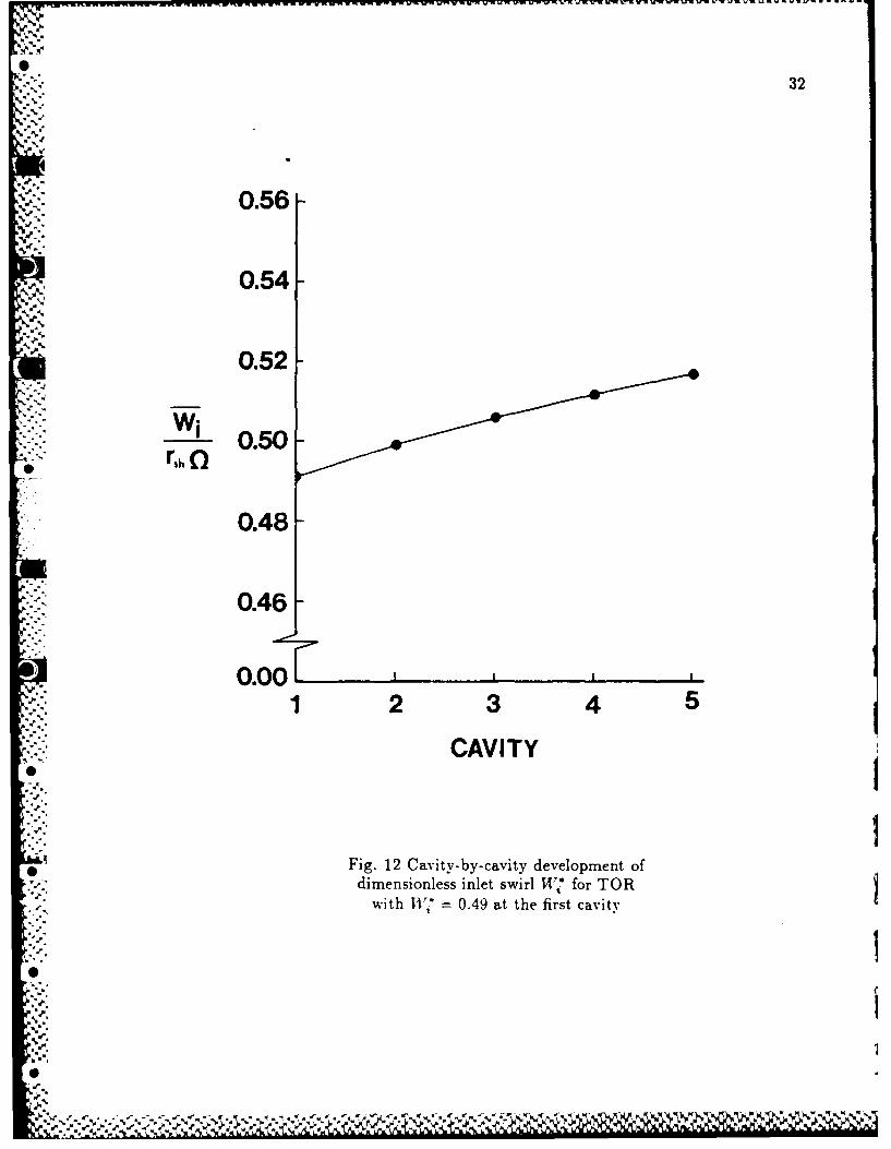
32
S.56
0.56-Se.
0.54-
0.52
rho
0.48-
0.46
0.001 2 3 4 5
CAVITY
Fig. 12 Cavi ty- by- cavity development ofdimensionless inlet swirl Tfi* for TOR
with W7 0.49 at the first cavity

33
x/L
. .2S .5 75 1.S
.995
. 991
* .98 1
.981
r/R.975
m .965
.96
.955
.95
U
Fig. 13 Cavity-by-cavity dimensionless axialvelocity distribution for TOR showing the
first cavity( ), third cavity(-and fifth cavity(- )
*1%

3
x/L
t. .25 .5 .75 1.
.99'
1 . i . I ,,
N-,,' ,K'K
"" Iaoo.985 Ii
.98 !Ir-/RI
., .976l
* II '4'
*Ii Ii I-"I', I! Ii.957 I
.6I.i i ~. q, .gg.-
•95 ,
'," rs h
4
,
- Fig. 14 Cavity-by-cavity dimensionless swirl* velocity distribution for TOR showing the
first cavity( ), third cavity(- -)
and fifth cavity(- )
5,'N
I

7-1
35
x/L
0..25 .5 .75 1.
U ~~995 \.~i s
3 .95
.985
r/R.q7S
.9q7
.965
5'.9'
.955
.9S
_x5
Fig. 15 Cavity-by-cavity dimensionless turbulencekinetic energy distribution for TOR showing the
first cavity( ),third cavity(- -and fifth cavity(- --
% V

36
most of the results are nearly identical to those for TOS. Major items of interest
again are approximate streamwise periodicity for axial velocity at the third cavity
and swirl profile development. One difference between corresponding TOS and TOR
-'2 cases is the swirl velocity profile in the leakage flow region. For the TOS case, Fig.
9 shows a larger 8, than does Fig. 14 for TOR. This is due to the fact that the
large shear stress r,.0 on the shaft acts on the leakage flow over the entire length
from cavity inlet to outlet for the TOS case.
Figure 16 clearly contrasts the faster swirl growth rate of TOR over TOS. This
leads to a higher asymptotic swirl velocity for TOR. Again, this is of significance
to designers interested in analyzing rotordynamic forces on the shaft.
0
,%-6
*1-.
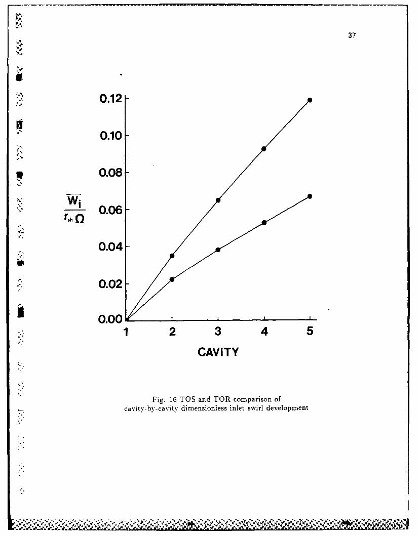
37
0.12
0.10
0.08
~0.06-
0.04
0.02
3 0.001 2 3 4 5
CAVITY
Fig. 16 TOS and TOR comparison ofcavity-by-cavity dimensionless inlet swirl development

38
CLOSURE
A finite aifference computer program for predicting compressible, axisymmetric
flow in labyrinth seals was used in investigating cavity-by-cavity growth of swirl
velocity and leakage Mach number effect on grid independence. Due to a current
lack of experimental data from compressible flow labyrinth seals, the results of this
computational study cannot be verified.
The Fanno flow behavior computed herein for the compressible flow in labyrinth
seals is well known. The steady increase in Mach number from one cavity to the next
translates into a significant decrease in density and pressure. These in turn were
found to give rise to a considerable grid dependence sensitivity at Mach numbers
* above approximately 0.4. Furthermore, predictions for corresponding TOR and
*. . TOS cavity designs with the same flow area and leakage rate showed that the TOR
cavity had approximately ten percent greater dimensionless pressure drop than the
TOS cavity. Thus, for a given pressure drop the TOR cavity is expected to leak
less.
Several conclusions concerning the cavity-by-cavity flowfield development can
also be drawn from the predictions presented. For example, it was clearly shown
that the cavity-by-cavity swirl velocity development is fairly slow. It is anticipated
that these values will prove helpful to the developers of simple models for predicting
* the rotordvnarnic fluid forces on such seals when the rotor is eccentric relative to
the stator. Specifically, such previously unavailable values may serve as a swirl
development prediction test case for such models, as the forces are sensitive to
* swirl velocity. Moreover, the TOS seals develop swirl velocity at a considerably
slower rate than do TOR seals. This indicates that TOS seals are less likely to have
significant destabilizing fluid forces which drive the rotor in the detrimental whirling
9'.,
..-0 . . . , - -, -.. .L ,,,-.------L ,.. . ., .

39
motion. Thus, the greater leakage tendency of TOS seals offsets this advantage of
j slower swirl velocity development.
In addition, the prediction of cavity-by-cavity flow development for Mach
numbers near 0.3 indicates that, except for swirl velocity, most quantities are
essentially streamwise periodic after the second cavity.
'
p.,
1~
5,..
-- --- -. S . * * '"s ' %tm , ''V .' *S-'**- *5 '~>. ''
40
ACKNOWLEDGEMENT
The financial support of AFOSR is greatly appreciated.
02
." 4
S.
a,.-'
m a.,
'.q
'..
a".-

41
REFERENCES
[1] Parsons, C. A., "The Labyrinth Packing,"Engineer, vol. 165, No. 4280, pp.23-84, Jan. 21, 1938
[2] Stoff, H., "Incompressible Flow in a Labyrinth Seal," Journal of Fluid Mechan.ics, vol. 100, pp. 817-829, 1980.
[3] Gosman, A. D. and Pun, W. M., "Calculations of Recirculating Flows," Re-search Report, Rept. No. HTS/74/2, Department of Mechanical Engineering,Imperial College, London, England, 1974.
[41 Rhode, D. L. and Sobolik, S. R., "Simulation of Subsonic Flow Through aGeneric Labyrinth Seal," ASME Journal of Engineering for Gas Turbines and
p Power, vol. 108, pp. 674-680, 1986.!5 Sobolik, S. R., "Prediction of Compressible Flow Within Concentric-Rotor
Labyrinth Seals," M. S. Thesis, Texas A&M University, 1984.
6 Sneck, H. J., "Labyrinth Seal Literature Survey," ASME Paper No. 73-Lub-12,1973.
71 Cogan, Kevin C., "Leakage Prediction of Incompressible Fluids in LabyrinthSeals," M. S. Thesis, Texas A&M University, College Station, Texas, December1982.
[8] Martin, H., "Labyrinth Packings," Engineering, vol. 85, pp. 35-38, Jan. 10,1908.
9' Stodola. A., Steam and Gas Turbines. New York: McGraw-Hill, 1927.
]10 Gercke, NI., "Flow Through Labyrinth Packing," Mechanical Engineer, vol. 56,i pp. 678-680, 1934.
11] Egli, Adolf, "The Leakage of Steam Through Labyrinth Seals," TransactionsASME, vol. 57, pp. 115-122, 1935.
1121 Dollin F., and Brown, W. S., "Flow of Fluids Through Openings in Se-ries,"Engineering, pp. 223-224, Aug. 27, 1937.
-'13] Hodkinson, B., "Estimation of the Leakage Through a Labyrinth Gland," Proc.
of Inst. Mech. Eng., vol. 141, pp. 283-286, 1939.
14] Kearton, W. and Keh, T., "Leakage of Air Through Labyrinth Glands ofStaggered Type," Proceedings of the Institute of Mechanical Engineers, vol. 166,pp. 180-194, 1952.
'151 Zabriskie, W. and Sternicht, B., "Labyrinth Seal Leakage Analysis," ASME
Journal of Basic Engineering, vol. 81, pp. 332-340, Sept. 1959.

42
[16] Vermes,.G., "A Fluid Mechanics Approach to the Labyrinth Seal Leakage
Problem," ASME Journal of Engineering for Power ,pp. 161-169, Apr. 1961.
[171 Rao, K. V. and Narayanamurthi, R. G., "An Experimental Study of thePerformance Characteristics of Labyrinth Seals," India Engineering Journal-ME, vol. 52, pp. 277-281, July 1973.
[18] Deich, M. Y., Shkvar, A. Ya, and Solomko, V. I., "Investigation of Straight-Through Labyrinth Seals," Izvestiya Akademii Nauk SSSR. Energetika i Trans.port, vol. 16, pp. 146-152, 1978.
[191 Benvenuti, E., "Analytical and Experimental Development of Labyrinth Sealsfor Process Centrifugal Compressors," presented at the 25th Annual Interna-tional Gas Turbine Conference and Exhibition, New Orleans, LA, March 9-13,1980.
[20] Hauck, L., "Measurement and Evaluation of Swirl-Type Flow in LabyrinthSeals of Conventional Turbine Stages," presented at the Workshop on Rotordy-namic Instability Problems in High-Performance Turbomachinery, Texas A&MUniversity, May 10-12, 1982.
21] Patankar, S. V., Numerical Heat Transfer and Fluid Flow. United States:p., Hemisphere Publishing Company, McGraw-Hill, 1980.
i'22' Spalding, D. B., "A Novel Finite-Difference Formulation for Differential Ex-pressions Involving both First and Second Derivatives," Int. J. Num. MethodsEng., vol. 4, pp. 551, 1972.
'23' Leonard, B. P., "A Stable and Accurate Convective-Modelling Procedure Basedon Quadratic Upstream Interpolation," Comp. Aleths. Appl. Mech. Eng.,vol. 19, pp. 59-98, 1979.
24 ' Zimmermann, H. and Wolff. K. I., "Comparison Between Empirical and Nu-
merical Labyrinth Flow Correlations." presented at the Gas Turbine Conferenceand Exhibition, Anaheim, California, May 31-June 4, 1987.
"r2 5 : Kirk, R. G., "A Method for Calculating Labyrinth Seal Inlet Swirl Velocity,"0." presented at the ASME 11th Biennial Conference on Mechanical Vibrations
and Noise, Boston, Massachusetts, September 27-30, 1987.
r261 Nordmann, R., Dietzen, F. J. and Weiser, H. P., "Calculation of Rotordynamic
... Coefficients and Leakage for Annular Gas Seals by Means of Finite DifferenceTechniques," presented at the ASME 11th Biennial Conference on MechanicalVibrations and Noise, Boston, Massachusetts, September 27-30, 1987.
27' Jerie, J., "Flow Through Straight-Through Labyrinth Seals," Proceedings of,., the Seventh Int. Cong. of App!. Mech.. vol.2, pp. 70-82, 1948.
". oI.."

43
[28; Bell, K. J., and Bergelin, 0. P., "Flow Through Annular Orifices," Transactionsof the ASME, vol. 79, pp. 593-601, April 1957.
r291 Nikitin," G. A. and Ipatov, A. M., "Design of Labyrinth Seals in Hydraulic
Equipment," Russian Engineering Journal, vol. 53, pp. 26-30, 1973.
[30" Han, J. T., "A Fluid Mechanics Model to Estimate the Leakage of Incompress-ible Fluids Through Labyrinth Seals," ASME Paper no. 79-FE-4 , 1979
f31V Rhode, D. L., Demko, J. A., Traegner, U. K., Morrison, G. L. and Sobolik, S.R., "Prediction of Inompressible Flow in Labyrinth Seals," ASME Journal ofFluids Engineering, vol. 108, No. 19, pp. 19-25, March 1986.
'.4t
[32 i Demko, J. A., "The Prediction and Measurement of Incompressible Flow in aLabyrinth Seal," Ph. D. Dissertation, Texas A&M University, 1986.
133' Demko, J. A., Morrison, G. L., and Rhode, D. L., "Effect of Shaft Rotationon the Incompressible Flow in a Labyrinth Seal," Proceedings of the 5thInternational Conference on Numerical Methods in Laminar and TurbulentFlows, Montreal, Canada, 7/6/87-7/10/87 (also accepted for publication inthe AIAA Journal of Propulsion and Power) 1986.
'34' Demko, J. A., Morrison, G. L. and Rhode, D. L., "The Prediction andMeasurement of Incompressible Flow in a Labyrinth Seal," AIAA paper 88-0190presented at the 26th Aerospace Sciences Conference, Reno, Nevada, January1988 (also accepted for publication by the ASME Journal of Engineering for
Gas Turbines and Power).
'35 Launder, B. E., and Spalding, D. B., "The Numerical Computation of Turbu-
lent Flows," Comp. Meth. in Appl. Mech. and Engr., vol. 3, pp. 269-289,1974.
'36 Leschziner, M. A. and Rodi, W.. "Calculation of Annular and Twin Parallel
Jets Using Various Discretization Schemes and Turbulence-Model Variations,"ASAE Journal of Fluids Engineering, vol. 103, pp. 352-360, 1981.
37i Han, T., Humphrey, J. A. C., and Launder, B. E., "A Comparison of Hy-
brid and Quadratic-Upstream Differencing in High Reynolds Number EllipticFlows," Comp. Meths. Appl. Mech. Eng., vol. 29, pp. 81-95, 1981.
I