Embed Size (px)
Citation preview

Aeroprakt Ltd.24, Polevaya str., Kiev, Ukraine
Tel: 0038 044 496-77-21
Fax: 0038 044 496-77-31
e-mail: [email protected]
www.aeroprakt.kiev.ua
AEROPRAKT-22L2
Airplane Maintenance Manual
A22L2-AMM-02

AEROPRAKT-22L2 Airplane Maintenance Manual A22L2-AMM-02
Model: AEROPRAKT-22L2 (A-22L2)
Serial No: 532
Registration:
Document No: A22L2-AMM-02
Date of issue: 06.03.2017
Approved by: Yuri Yakovlyev
Signature:
Position: Chief Designer
Stamp:
Date of approval: 06.03.2017
This airplane is to be serviced and maintained in compliance with information and instructions contained herein.
2

AEROPRAKT-22L2 Airplane Maintenance Manual A22L2-AMM-02
RECORD OF REVISIONS
No part of this manual may be reproduced or changed in any manner without a written consent of the Manufacturer.
Any revision of the present manual, except actual weighing data, must be recorded in the following table according to information from the Manufacturer.
New or amended text in the revised pages will be indicated by a black vertical line on the left hand margin, and the Revision No. and the date will be shown on the bottom left hand side of the page.
Rev. No.Affected Section
Affected Pages
Date Approval DateDate
InsertedSignature
3

AEROPRAKT-22L2 Airplane Maintenance Manual A22L2-AMM-02
LIST OF EFFECTIVE PAGES
Section Page Date Section Page Date
4

AEROPRAKT-22L2 Airplane Maintenance Manual A22L2-AMM-02
Contents1 GENERAL............................................................................................................................................... 6
2 AIRFRAME.............................................................................................................................................. 7
3 LANDING GEAR.................................................................................................................................... 11
4 BRAKE SYSTEM................................................................................................................................... 15
5 ENGINE AND ITS CONTROL SYSTEM................................................................................................19
6 COOLING SYSTEM............................................................................................................................... 23
7 LUBRICATION SYSTEM.......................................................................................................................24
8 FUEL SYSTEM...................................................................................................................................... 25
9 EXHAUST SYSTEM.............................................................................................................................. 27
10 PROPELLER......................................................................................................................................... 28
11 AIRPLANE CONTROL SYSTEM..........................................................................................................29
12 ELECTRICAL SYSTEM.........................................................................................................................34
13 COCKPIT HEATING SYSTEM..............................................................................................................37
14 FULL AND STATIC PRESSURE SYSTEM............................................................................................38
15 PILOT SEATS AND HARNESS BELTS................................................................................................39
16 COCKPIT DOORS................................................................................................................................. 40
17 RECOVERY SYSTEM........................................................................................................................... 41
18 GLIDER AND BANNER TOWING SYSTEM.........................................................................................42
19 Inspection Schedule for A-22L2 airplane................................................................................................43
5

AEROPRAKT-22L2 Airplane Maintenance Manual A22L2-AMM-02
1 GeneralWARNING! The safety bulletins are published at the official website of Aeroprakt company http://www.aeroprakt.kiev.ua.
This manual describes the procedures of proper aircraft handling and servicing recommended by the aircraft manufacturer. It also specifies the requirements to inspection and maintenance that are required for keeping the flight performance and reliability at a level of a new airplane. It is recommended to adhere to the scheduled periods of greasing/lubrication and preventive maintenance taking into account the climate and operating conditions.
This manual contains the check lists with information about check periods, recommended change out (RCO) times as well as references for servicing of all airplane parts.
Before expiration of the recommended change out time of separate airplane parts or when it is not specified their operation shall be performed on condition (OC). Such parts must be inspected and replaced, if necessary, before expiration of the RCO (if specified).
If inspections and checks aroused issues not covered in this manual contact the manufacturer for additional information.
Upon detecting corrosion on airplane structural elements contact the manufacturer for the required technical support. In this case further operation of the airplane may be dangerous!
In A-22L2 all fasteners in front of the firewall and in the electrical system is metric and rear of the firewall – inch. The torque of the screws and nuts (unless specified otherwise) are as follows:
1. For the static joints joints with spacing inserts (spacers, spherical bearings, etc.) according to the table:
Metric fasteners Inch fasteners Torque, Nm (lb·ft)
М5 10-32 6 (4.4)
М6 1/4 10 (7.4)
М8 5/16 15 (11.0)
М10 3/8 25 (18.4)
2. For the movable joints where bolts serve as hinge axle the nuts tightening must be done only to remove the axial play (gap) while preserving the rotational freedom in the joint.
WARNING! All bolts, nuts (except for self-locking ones), pins, turnbuckles must be locked reliably.
6

AEROPRAKT-22L2 Airplane Maintenance Manual A22L2-AMM-02
2 AirframeThe airframe of A-22L2 airplane includes the following parts: fuselage with polycarbonate glass windscreen and rear skin panels, wings, wing struts, horizontal and vertical tail units (HTU and VTU), wing fillets, strut fairings and engine cowling. Fuselage with fin, wing struts and stabilizer are made of aluminum alloys. Wing framework including leading edge section and top skin are all-metal and bottom skin is fabric. Framework of flaperons, elevator and rudder is all-metal, their rear skin (aft of spar) is fabric. The rear fuselage skin panels (top and two side ones) depending on airplane configuration may be made of PVC glass, all-metal or combined. The fairings and engine cowling are made of fiberglass.
When servicing the airplane a special care shall be taken to protect the airframe from corrosion and to protection of the paint coating. Protection of the airframe parts from corrosion consists mainly of keeping the protective coatings intact. Care of the fabric skin consists mainly of care of its paint coating. Correct care of the paint coating is one of the conditions of preserving the airplane strength and aerodynamic characteristics. To keep the paint coating of the airplane in good condition the dust and moisture must be removed in time, the paint must be protected from scratches, and spilling oil products, solvents, alkalis and acids on paint must be avoided.
INSPECTION CHART
Part No. DescriptionInspection
intervalRCO Note
A22L2-0-0100-00 Fuselage 500 h OC 2.1
A22LS-0-1300-00 Windscreen glass 100 h OC 2.2
A22L-0-1320-00 Rear fuselage skin panel, top 100 h OC 2.2
A22L-0-1330-01 Rear fuselage skin panel, right 100 h OC 2.2
A22L-0-1330-02 Rear fuselage skin panel, left 100 h OC 2.2
A22L2-0-2000-00 Wing 500 h OC 2.3
COM-5 Spherical bearing ×4 2000 h OC 2.4
A22LS-1-2920-01 Wing strut, right 500 h OC 2.5
A22LS-1-2920-02 Wing strut, left 500 h OC 2.5
A22LS-0-2950-01 Wings strut fairing, top, right 200 h OC 2.6
A22LS-0-2950-02 Wings strut fairing, top, left 200 h OC 2.6
A22LS-0-2940-01 Wings strut fairing, bottom, right 200 h OC 2.6
A22LS-0-2940-02 Wings strut fairing, bottom, left 200 h OC 2.6
AN 175-11 Wing attachment bolt ×4 100 h OC Torque
AN 175-12 Wing attachment bolt ×4 100 h OC Torque
A22LS-0-3100-00 Stabilizer 100 h OC 2.7
AN 174-6 Stabilizer attachment bolt ×2 100 h OC Torque
AN 310-5 Stabilizer attachment nut 100 h OC Torque
- Tail wheel 100 h OC 2.8
AN 5-32 Tail wheel bolt 100 h OC Torque
A22L-2-6920-00 Engine cowling panel, top 100 h OC 2.9
A22L-2-6910-00 Engine cowling panel, bottom 100 h OC 2.9
7
AEROPRAKT-22L2 Airplane Maintenance Manual A22L2-AMM-02
Notes:
2.1 Remove the engine cowling, doors, wing strut fairings (undo the screws fixing the fairings and 'slide' them along the strut), pilot seats, and rugs. Inspect the fuselage for cracks and deformation, paying special attention to primary structural elements, areas of their connection and rivet joints (frames No. 1, 4, 5, 6, longitudinal, transverse and vertical beams of the cockpit, undercarriage beam, fuselage tubes, tail boom and fin skin).
Inspection for fatigue cracks. Use torch or any other suitable source of light. When detecting very thin cracks remove the paint in the area of the suspected crack for a closer flaw detection. If possible apply load in this area in a manner that will 'open up' the crack. If the closer inspection confirmed the crack existence contact the manufacturer for required technical support. If the suspected crack was not detected repaint this area.
Inspection for loose rivets. When inspecting rivet joints look at the area around river heads. The paint around the rivet heads must have no cracks or black stains that indicate on loose and corroded rivet joint. When detecting such flaws contact the manufacturer for the required technical support.
If no flaws were detected reinstall everything in the reversed order. Apply Loctite 222 on the thread of the attachment screws of the wing strut fairings before reinstalling them.
2.2 Inspect the glass for 'silvering' (micro cracks) and cracks in the attachment areas. When detecting a crack shorter than 50 mm (2 in) carefully cut a hole at its end with a Ø3 mm (0.12 in) drill to stop the crack propagation. If the crack is longer than 50 mm (2 in) the glass must be replaced. Contact the manufacturer for glass replacement instructions.
WARNING! The glazing material is not resistant to fuels, oils and solvents. Spilling those liquids on glazing may cause its dimness and cracking.
2.3 Drain fuel from the fuel tanks. Remove the wing strut fairings and fuel tanks. Inspect the wing for fatigue cracks, deformation and loose rivets as described in 2.1 (2nd and 3rd paragraph). Pay special attention to the strut-to-wing attachment points, rivet joints of the wing leading edge section and top skin.
Inspect the fabric skin for damage and detachment from the wing framework. It is allowed to repair small cuts/ruptures (shorter 50 mm or 2 in) covering them with ORACAL permanent sticking film. Upon detecting bigger damages and delaminations of the fabric skin from the framework contact manufacturer for the required technical support.
Verify that there is no play in attachment points of the wing and strut by holding the wingtip gently and moving it up and down with an amplitude of 300 mm (1 ft). The movement in the attachment points due to loose joint (play) is not allowed. When detecting insignificant radial play (less than 0.2 mm or 0.01 in) in the strut attachment points it must be eliminated by tightening its bolt joint. In case if the play is more than 0.2 mm (0.01 in) contact the manufacturer for the required technical support.
In case if no defects are found re-assemble everything in the reversed order. Before re-installing the screws attaching the fuel tanks and strut fairings apply Loctite 222 on the thread.
8

AEROPRAKT-22L2 Airplane Maintenance Manual A22L2-AMM-02
2.4 Detach the wings by doing the following:
- detach the doors;- drain fuel from the fuel tanks;- disconnect the fuel lines from the fuel valves, close the valves, plug the fuel lines
and pull them out of cockpit through the rubber sealing rings in fuselage beams;
CAUTION! Be careful while working with the fuel system, the fuel remaining in the fuel lines is highly fire-hazardous and when spilled on the cockpit glass may cause glass dimness and cracking.
- disconnect the electric connectors of the navigation lights and fuel level probes at wing root and take the cables out of fuselage;
- detach the strut fairings (undo the screws attaching the fairings and slide fairings along the struts);
- detach the Cardan rings from the flapperon shafts by removing the vertical bolts;- remove the split pins and undo the nuts from wing and strut attachment points;- while holding the wing by the tip and strut carefully take out the strut attachment
bolts and remove the struts;- while holding the wing by the tip and at the root take out the wing attachment bolts
and slowly move the wing away from fuselage carefully pulling the navigation light from the wing fillets;
Inspect the wing and strut attachment fittings for fatigue cracks. Check the spherical bearing for axial and radial play. When detecting play in bearings, as well as corrosion and fatigue cracks in the attachment fittings contact the manufacturer for the required technical support.
If no defects were detected re-assemble everything in the reversed order. Before reinstalling the screws attaching the fuel tanks and strut fairings apply Loctite 222 on the thread.
2.5 Remove the strut fairings (undo the screws attaching the fairings and slide fairing along the strut). Inspect the struts for fatigue cracks, deformation (bend) and loose rivets as described in 2.1 (2nd and 3rd paragraph).
If no defects were found re-install the fairing applying Loctite 222 on the thread of the attaching screws.
2.6 Undo the screws attaching the fairings and slide the fairings along the strut. Inspect the sealing fabric tape in the inner side. If necessary use double-sided sticking tape to fix the tape.
Re-install the fairings applying Loctite 222 on the thread of the attaching screws.
2.7 Inspect the stabilizer for fatigue cracks, deformation and loose rivets as described in 2.1 (2nd and 3rd paragraph). Pay special attention to the areas near the stabilizer attachment fittings and leading edge near the hole for elevator trim tab cable.
Verify that there is no play in the stabilizer attachment joints by gently moving the stabilizer by its tip up and down with an amplitude not more than 50 mm (2 in).
CAUTION! The applied load may not exceed 30 N (7 lb).
There must be no movement due to the play in the attachment joints. When detecting insignificant play (less than 0.2 mm or 0.01 in) it must be eliminated by tightening the relevant bolted joint. In case if the play exceeds 0.2 mm (0.01 in) contact the manufacturer for the required technical support.
9
AEROPRAKT-22L2 Airplane Maintenance Manual A22L2-AMM-02
2.8 Inspect the tail wheel for damage and play. When detecting a serious damage replace the wheel. When detecting play below 0.5 mm (0.02 in), tighten its axle nut. If the play exceeds 0.5 mm (0.02 in), insert a washer of appropriate thickness between the wheel hub and fuselage. Tighten the axle nut until it stops the free rotation of the wheel.
2.9 Remove the top and bottom engine cowling and inspect for cracks, ruptures, as well as damaged paint coating. When detecting damaged paint coating sand the damaged area with sandpaper and re-paint. When detecting cracks and ruptures sand the damaged area from inside with sandpaper and cover it with a patch of fiberglass cloth with epoxy resin. After the resin solidifies properly, sand the damaged area outside with sandpaper and re-paint.
10

AEROPRAKT-22L2 Airplane Maintenance Manual A22L2-AMM-02
3 Landing gearA-22L2 may have the landing gear (LG) of one of the following three types: wheels, skis or floats. This manual contains the information for servicing the wheel and ski LG. The float type LG is not included in this manual. For obtaining additional information contact the manufacturer.
When put on wheels the airplane is equipped with wheels of Matco mfg.
NOTE! When installing wheels tighten the axle nut as follows: first tighten the nut to remove the axial play, then turn it back until its slots alight with the hole for the split pin in the axle. Then lock the nut using the split pin.
The nose LG leg is steerable, of trailing link type with spring shock absorber. The leg structure consists of the strut, trailing link, bellcrank, wheel fork, spring shock absorber, axle, spacing sleeves, wheel/ski and fairing/mud-screen. The steering is achieved using the rudder pedals via the rods connected to the bellcrank on the strut. The leg is attached to the firewall at two points – lower and upper supports. The upper support is made of D16T plate, the lower support is an assembly. The supports contain bronze bearings.
Main landing gear (MLG) is of cantilever spring type. The MLG leg consists of the spring, axle, wheel (or ski), brake unit with supporting plate, and fairing (or mud-screen). The MLG spring is made of aluminum alloy. It is bolted at two points to the lower beam of the frame No.2.
Maintenance of the brake unit with supporting plate is described in "Brake system" section.
INSPECTION CHART
Part No. DescriptionInspection
intervalR.C.O Note
A22LS-4-4310-00 Nose leg 100 h OC 3.1
AN 4-22A Bellcrank bolt 100 h OC Torque
165x40 mm Spring shock absorber 100 h OC 3.2
A22LS-3-4110-00 Main leg, right 100 h OC 3.3
A22LS-3-4110-00 Main leg, left 100 h OC 3.3
AN 6-37 Spring bolt, upper х2 100 h OC Torque
AN 7-41 Spring bolt, lower х2 100 h OC Torque
See Matco P/N Nose wheel assembly 200 h OC 3.4
See Matco P/N Right wheel assembly 200 h OC 3.4
See Matco P/N Left wheel assembly 200 h OC 3.4
А32-1-325101-00-000 Nose wheel fairing 50 h OC 3.5
A22LS-0-4420-01 Right wheel fairing 50 h OC 3.5
A22LS-0-4420-02 Left wheel fairing 50 h OC 3.5
A22LS-0-4510-00 Nose wheel mud-screen* 50 h OC 3.6
A22LS-0-4520-01 Right wheel mud-screen* 50 h OC 3.6
A22LS-0-4520-02 Left wheel mud-screen* 50 h OC 3.6
A22LS-0-4710-00 Nose ski** 100 h OC 3.7
A22LS-0-4610-01 Right ski** 100 h OC 3.7
A22LS-0-4610-02 Left ski** 100 h OC 3.7* – for wheel version with mud-screens;** – for ski version.
11

AEROPRAKT-22L2 Airplane Maintenance Manual A22L2-AMM-02
Notes:
3.1 Remove the nose wheel fairing. Inspect the nose leg for fatigue cracks, deformation and play. When inspecting follow the instructions of 2.1 (2 and 3 paragraph) of "Airframe" section.
Pay special attention to the areas of the nose leg attachment near its upper and lower supports as well as weld seams of the nose leg.
Check the nose leg supports for play. The radial play in the supports may not exceed 1 mm (0.04 in). No axial play is allowed.
If the radial play in the upper support exceeds the above specified value then the bronze bearing in the support must be replaced. If the radial play in the lower support exceeds the above specified value then the support with bearing must be replaced. Contact manufacturer to obtain the instructions on replacement of the bearing and support.
Upon detecting axial play in the supports tighten the upper support nut until play is eliminated, if necessary, insert a washer of an appropriate thickness.
WARNING! Tightening the nut must eliminate the play while ensuring free rotation of the leg in the supports. Do not over-tighten the nut!
Check the torque of all bolted joints with self-locking nuts.
Lubricate all surfaces of the nose leg trailing link subjected to friction depending on their condition as follows:
- set parking brake to ON;- disconnect the control rods from the nose leg bellcrank;- remove the split pin and undo the nut of the upper support of the nose leg;- undo the nut and take out the bellcrank bolt;- while holding the nose leg carefully push down the airplane tail near the stabilizer
attachment points till the airplane sets on the tail wheel and hold it in this position till the nose leg is re-installed back (this operation must be done by two persons);
- carefully take out the nose leg from the supports simultaneously removing the bellcrank from it;
CAUTION! Do not lower the fuselage nose while the nose leg is removed! This may cause damage to the airframe and propeller.
- remove the old grease from the surfaces of the nose leg trailing link subjected to friction;- apply thin layer of new grease;- re-install the leg in the reversed order;- squirt grease into the nose leg hinge till grease comes out;- remove the excessive grease with rags.
Any lubricating grease for bearings may be used for the nose leg.
After servicing the nose leg reinstall the nose wheel fairing.
If the spring shock absorber is seriously damaged, then it must be removed for repair or replacement.
To remove the spring shock absorber do the following:
- set the parking brake to ON;- remove the nose wheel fairing;- remove the split pins and undo the nuts of the shock absorber attachment;- carefully push down the airplane tail near the stabilizer attachment points till the
airplane sets on the tail wheel and remove the spring shock absorber (this operation must be done by two persons);
12

AEROPRAKT-22L2 Airplane Maintenance Manual A22L2-AMM-02
- set the airplane level on a wooden support under its bottom as close to the frame No. 1 (firewall) as possible (the support width must be equal or bigger than the fuselage width).
To reinstall the shock absorber perform the above actions in the reversed order. Before installation of the shock absorber lubricate its attachment bolts with bearing grease.
WARNING! When installing the shock absorber tighten the nuts as follows: first tighten to remove the axial play, then rotate a little back to alight the nearest slot of the castle nut with the hole for the split pin and secure it with a split pin. Tightening of the shock absorber bolts must not restrict its free motion.
3.2 Remove the pilot seat and wheel fairing. Inspect the MLG attachment beam and spring for fatigue cracks, deformation and play following the instructions of 2.1 (2nd
and 3rd paragraph) of "Airframe" section. Pay special attention to the areas of the spring attachment to the beam and wheel axle attachment to the spring.
If axial play is detected in the MLG attachment, check the attachment bolts' torque. If radial play is detected, contact the manufacturer to obtain the required technical support.
After 5000 landings careful inspection of the MLG spring is required. The MLG leg must be removed for that.
To remove the MLG leg do the following:
- put the wheel chokes under the nose and opposite main wheel;- remove the pilot seats;- remove the wheel fairing;- cut the plastic ties fixing the brake system tube to the MLG spring;- lift the airplane using a jack placed under a special plate near the opening in the
fuselage bottom skin for the MLG spring;- remove the safety wire and undo the brake disk screws and wheel axle nut;- remove the wheel and brake disk;- leaving the braking system tube assembled, disconnect the braking unit from the
supporting plate (undo two bolts and three screws of the braking unit and move the brake unit with the tube aside);
WARNING! When handling the brake pads and disk avoid smearing their working surfaces with any lubricating materials. Do not use braking system with a braking disk removed.
- remove the split pins and undo the nuts of the upper and lower bolts of the MLG spring attachment and carefully force the bolts out of the holes;
- remove the spring.
Inspect carefully the spring and fittings of the MLG attachment beam for fatigue cracks. Pay special attention to the areas around the attachment holes in the beam and spring. Upon detecting fatigue cracks in the MLG spring or MLG attachment beam contact the manufacturer to obtain the required technical support.
If no defects were detected, install the MLG leg back by doing the above actions in the reversed order.
Before re-installing the attachment screws of the brake disk and pilot seats apply Loctite 222 on their thread.
3.3 Remove the wheel fairing. Inspect the tire for cracks and cuts. Determine the nature and degree of the tire wear. In case of normal operation the wear will be uniform over
13

AEROPRAKT-22L2 Airplane Maintenance Manual A22L2-AMM-02
entire operating surface of the tire. Tire operation is allowed until exposure of its cord. In case if exposed cord or deep cuts are detected the tire must be replaced.
To replace the nose wheel tire do the following:
- set the parking brake to ON;- remove the split pin of the nose wheel axle nut and undo it;- carefully push down the airplane tail near the stabilizer attachment points till the
airplane sets on the tail wheel and remove the nose wheel (this operation must be done by two persons);
- put the airplane’s nose down placing a wooden support under the nose wheel fork;- replace the tire;- inflate the wheel (1.6 bar) and install it back on the airplane making the above
actions in the reversed order.
To replace a main wheel tire do the following:
- put wheel chokes under the opposite main wheel and nose wheel;- remove the split pin of the main wheel axle nut and undo it;- lift the airplane using a jack placed under a special plate near the opening in the
fuselage bottom skin for the MLG spring;- remove the safety wire and undo the brake disk screws and wheel axle nut;- remove the wheel;- replace the tire;- inflate the wheel (1.6 bar) and install it back on the airplane making the above
actions in the reversed order.
Before re-installing the attachment screws of the brake disk apply Loctite 222 on their thread.
If no defects were found, check the wheel pressure and inflate if necessary. The pressure must be equal to 1.6 bar. Install the wheel fairing after servicing.
For more detailed information regarding the servicing (repairing) the wheels visit the manufacturer’s web site http://www.matcomfg .com.
3.4 Inspect the fairing for cracks, ruptures and paintwork damage. If damaged paint is detected, remove the fairing, clean the damaged area with sand paper and repaint. If cracks and ruptures were detected, remove the fairing, clean the damaged area with sand paper from inside, and apply a patch of fiberglass cloth with epoxy resin. After the resin solidifies properly, sand the damaged area outside with sandpaper and re-paint.
Check the torque of the fairing attachment bolts/nuts.
3.5 Inspect the mud-screens for fatigue cracks and deformation. Pay special attention to the areas around the bolt joints and mud-screen framework weld seams. If any cracks are detected in the mud-screen it must be replaced. If cracks are detected in the mud-screen framework they must be welded using argon-arc welding or the framework must be replaced.
Check the torque of the mud-screen attachment bolts/nuts.
3.6 Inspect the ski for mechanical damage. If damage of the paintwork is detected , clean the damaged area with the sand paper and re-paint. In case of serious damage of the ski contact the manufacturer for the required technical support.
Check the torque of the ski attachment bolts/nuts.
14
AEROPRAKT-22L2 Airplane Maintenance Manual A22L2-AMM-02
4 Brake systemThe main wheels are equipped with Matco mfg hydraulic disk brakes. The brake system includes: expansion tank, master cylinder with lever, parking brake valve, brake units with supporting plates, brake disks, copper tubes, fittings and reinforced rubber hose. The brake system is filled with transmission fluid ATF, one of the fluids recommended by Matco mfg. The amount of the fluid in the system can be checked by its level in the expansion tank that must be not less than half of the tank.
When servicing the brake system it may be necessary to disconnect its tubes. After such disconnection air gets into its cavities which is inadmissible. After such action it is necessary to fill the brake system with fluid to force all air out.
To fill the brake system with braking fluid in the airplane version with yokes, do the following:
- check the level of the braking fluid in the expansion tank and refill if necessary;
WARNING! Use only the fluid that is recommended by Matco mfg. Do not mix up the fluids of different grade. This may cause damage to the components and failure of the brake system.
- remove the cover set the parking brake valve to "OFF";- remove protecting cap from the brake unit nipple and put on it a transparent PVC
tube with the inner diameter of 3 mm (1/8 in) and minimum length of 300 mm (1 ft). The other end of the tube put into a container with the braking fluid so that it is completely submerged into the fluid;
- while holding the tube loosen the nipple by ½ turn;- pump the braking fluid through the system with the braking lever till air bubbles stop
appearing completely in the transparent tube (they may start appearing after some time of such pumping); while doing it do not forget to add braking fluid into the expansion tank to avoid air inflow into the system;
- after air bubbles disappear, tighten the braking unit nipple, remove the PVC tube and put on the protecting cap;
- repeat above actions for the other wheel.
To fill the brake system with braking fluid in the airplane version with central stick, do the following:
- remove the stick cover;- remove the stick from the roll torque tube;- remove the parking brake;- remove the clamps holding the brake system tubes;- put the stick on the longitudinal beams of fuselage with the braking cylinder nipples
up and pump the brake system through as described above for the airplane version with yokes;
- re-assemble everything in the reversed order.
WARNING! When filling the brake system it is necessary to pump through it braking fluid in the amount of 1 to 2 volumes of the expansion tank.
For more detailed information about maintenance (repair) of the brake system components visit its manufacturer web site: http://www.matcomfg.com.
15

AEROPRAKT-22L2 Airplane Maintenance Manual A22L2-AMM-02
INSPECTION CHART
Part No. DescriptionInspection
intervalR.C.O Note
- Expansion tank 100 h OC 4.1
See Matco P/N Master cylinder 200 h OC 4.2
See Matco P/N Parking brake valve 200 h OC 4.3
See Matco P/N Brake unit assembly, right 200 h OC 4.4
See Matco P/N Brake unit assembly, left 200 h OC 4.4
See Matco P/N Brake disk, right 200 h OC 4.5
See Matco P/N Brake disk, left 200 h OC 4.5
- Copper tubes 200 h OC 4.6
- Reinforced rubber hose 200 h OC 4.6
Notes:
4.1 Remove the top engine cowling. Inspect the expansion tank for leaks of braking fluid, cracks in its housing and cap. If the tank is damaged it must be replaced, then the brake system must be filled with braking fluid, following the instructions described in the beginning of this section.
Check the fluid level in the tank and refill if necessary. The required level is at least half of the tank.
Make sure the tank attachment to the firewall is secure. Replace the plastic binders if necessary.
4.2 Remove handles from the control levers of the throttle, trim tab, brake and remove the horizontal panel. Inspect the master cylinder for leaks of braking fluid. If leaks are detected, it must be removed for repair or replacement.
In order to remove the master cylinder, do the following:
- remove the left seat;- remove the panel between pilot seats;- disconnect the control cables of the engine and elevator trim tab (first from the
engine and trim tab ends, and then from the control levers);- undo the screws of the control lever unit (9 pcs.);- block the reinforced rubber hose near the master cylinder by squeezing it with a
clamp and disconnect it from the master cylinder;- disconnect the copper tube connecting the parking brake valve with brake units;
WARNING! When disconnecting the brake system tubes some amount of braking fluid may spill out.
- remove the control lever unit assembled with the master cylinder;- detach the master cylinder from the control lever unit;
To install the master cylinder perform the above actions in the reversed order. After re-assembling fill the brake system following the instructions given in the beginning of this section. Then adjust the control systems of the engine and elevator trim tab as described in the corresponding sections of this manual.
If no defects were detected in the master cylinder re-assemble everything in the reversed order.
16

AEROPRAKT-22L2 Airplane Maintenance Manual A22L2-AMM-02
4.3 Remove the handles from the control levers of the throttle, elevator trim tab, brakes and the horizontal panel. Inspect the parking brake valve for leaks of the braking fluid.
If any leak is detected the valve must be removed for repair or replacement.
In order to remove the parking brake valve do the following:
- block the reinforced rubber hose connecting the expansion tank with the master cylinder by squeezing the hose with a clamp;
- cut the plastic binders fixing the valve;- undo the screws attaching the valve;- disconnect the copper tubes from the valve.
To install the parking brake valve back perform the above actions in the reversed order. After assembling fill the brake system with the braking fluid following the instructions described in the beginning of this section.
If no defects are detected in the parking brake valve, re-assemble everything in the reversed order.
4.4 Remove the wheel fairing. Inspect the brake unit for the leaks of the braking fluid. If any leak is detected the brake unit must be removed for repair or replacement.
To remove the brake unit, do the following:
- put the wheel chokes under the nose and opposite main wheel;- lift the airplane using a jack placed under a special plate near the opening in the
fuselage bottom skin for the MLG spring;- unlock and undo the brake disk screws and wheel axle nut;- remove the wheel and brake disk;- disconnect the copper tube from the brake unit;- disconnect the brake unit from the supporting plate (undo two bolts and three
screws of the brake unit) and remove the braking pads from it.
To re-install the brake unit perform the above actions in the reversed order. After assembling fill the brake system following the instructions described in the beginning of this section.
Check the brake pads for integrity and wear. The minimum thickness of the pad is 2.54 mm (0.1 in). The wear may be checked using a special depression in the butt of the braking pad. In case of serious wear or loss of integrity the pads must be replaced. In order to do that, detach the brake unit as described above and replace the brake pads (the braking system tubes need not to be disconnected from the brake unit). For more detailed instructions on servicing and replacement of the brake pads contact the manufacturer (Matco mfg).
If the wear is within the permissible limits, re-assemble everything in the reversed order. Before re-installing the attachment screws of the brake disk apply Loctite 222 on their thread.
4.5 Define the nature and degree of the brake disk wear. For that remove the brake disk as described in 4.4. Measure the brake disk thickness at its working surface. It must be at least 3.3 mm (0.13 in). If the disk thickness is less than that, the brake disk must be replaced. For more detailed instructions on servicing and replacement of the brake disk contact the manufacturer (Matco mfg).
If the wear is within the permissible limits, re-assemble everything in the reversed order. Before re-installing the attachment screws of the brake disk apply Loctite 222 on their thread.
17

AEROPRAKT-22L2 Airplane Maintenance Manual A22L2-AMM-02
4.6 Remove the handles from the control levers of the throttle, elevator trim tab and brakes, horizontal panel, main wheel fairings and pilot seats. Inspect the tubing of the brake system for leaks and damage. Pay special attention to the joints. If leaks and damage is detected replace the corresponding portion of the tubing. To obtain additional technical support contact the manufacturer.
After re-assembly fill the brake system following the instructions described in the beginning of this section.
After inspection (repair) re-assemble everything in the reversed order. Before re-installing the pilot seats apply Loctite 222 on the thread of the attaching bolts.
18

AEROPRAKT-22L2 Airplane Maintenance Manual A22L2-AMM-02
5 Engine and its control systemA-22L2 is equipped with a 100 hp Rotax-912ULS four-cylinder four-stroke engine with combined cooling system manufactured by Rotax GmbH (Austria).
WARNING! Maintenance of the engine must be performed according to the current documentation of ROTAX company on operation and maintenance of Rotax 912 engine. For more detailed information visit the engine manufacturer’s web site http://flyrotax.com .
Arrangement and design of the engine systems (fuel, electric, oil, cooling, control, exhaust) complies with the requirements of the “Installation Manual for Rotax-912 aircraft engine”.
The engine is installed on a mount and is retained on top with a rod. The engine mount consists of upper and lower parts. The lower mount (truss) is attached to fuselage structure (firewall), and the upper mount (frame) is attached to the engine. To damp the vibrations produced by the engine the upper and lower mounts are connected via rubber shock absorbers. The shock absorbers are installed on the upper mount. The rod connects a bracket installed on the engine with fuselage structure. The rod is connected to fuselage structure via a shock absorber as well.
The throttle lever is located between the pilot seats. In the airplane equipped with a central stick the throttle levers are located outboard of the pilot seats. Two cables run from the throttle lever(s) to the left and right carburetors. The engine control system also includes engine start mixture control. The mixture control lever is located between the pilot seats. It is connected to the carburetors’ chokes with cables.
The engine may be equipped with an intake air box of Aeroprakt design that improves the engine operating conditions, prevents carburetor icing and increases the engine power output in hot climate.
INSPECTION CHART
Part No. DescriptionInspection
intervalR.C.O Note
Rotax 912 ULS Engine * OC 5.1A22L-3-6402-00 Engine mount, upper 200 h OC 5.2A22L-2-6401-00 Engine mount, lower 200 h OC 5.2A22L-0-6404-00 Engine retaining rod 200 h OC 5.2
See Gumokov P/N Shock absorber х6 500 h OC 5.3A22-1-6405-00 Engine attachment fitting 2000 h OC 5.4A22L-1-6570-00 Intake airbox assembly** 200 h OC 5.5
A22LS-2-6030-01*** Throttle cable right 100 h OC 5.6A22LS-2-6030-02*** Throttle cable left 100 h OC 5.6
A22LS-3-6030-01 Throttle cable right 100 h OC 5.6A22LS-3-6030-02 Throttle cable left 100 h OC 5.6
A22LS-2-6056-01*** Choke cables right 100 h OC 5.6A22LS-2-6056-02*** Choke cables left 100 h OC 5.6
A22LS-3-6056-01 Choke cables right 100 h OC 5.6A22LS-3-6056-02 Choke cables left 100 h OC 5.6
A22LS-0-6021-01*** Throttle cable sheath right 100 h OC 5.7A22LS-0-6021-02*** Throttle cable sheath left 100 h OC 5.7
A22LS-1-6011-01 Throttle cable sheath right 100 h OC 5.7A22LS-1-6011-02 Throttle cable sheath left 100 h OC 5.7
A22LS-0-6054-01*** Choke cable sheath right 100 h OC 5.7A22LS-0-6054-02*** Choke cable sheath left 100 h OC 5.7
A22LS-1-6054-01 Choke cable sheath right 100 h OC 5.7
19

AEROPRAKT-22L2 Airplane Maintenance Manual A22L2-AMM-02
Part No. DescriptionInspection
intervalR.C.O Note
A22LS-1-6054-02 Choke cable sheath left 100 h OC 5.7A22LS-3-6007-00 Throttle lever 100 h OC 5.8
* - see "Maintenance Manual for Rotax Engines. Rotax-912 Serie"** - in aircraft version equipped with intake airbox.*** – for the airplane version with central control stick.
Notes:
5.1 The engine servicing must be performed according to "Maintenance Manual for Rotax® Engine Type 912 Series". When servicing and repairing the engine it may be necessary to dismantle it. The plastic binders securing the engine system components must be cut. When disconnecting the tubes and hoses it is recommended to plug the holes and fittings. When installing the engine back secure the cables and tubes of the engine systems with the plastic binders.
To dismantle the engine, do the following:
- set the fuel valves to CLOSED;- switch OFF the battery using the battery switch or (if it is not available) disconnect
one of the power lines from the battery;- remove the top and bottom engine cowlings;- disconnect the fuel line at its joint behind the firewall;
WARNING! Be careful when working with the fuel system, as remains of fuel in the fuel lines are highly fire hazardous.
- remove the muffler and exhaust pipes (see “Exhaust system” section);- disconnect the throttle and choke control cables from the carburetors;- remove the intake air box (see 5.5 of this section);- drain the coolant from the cooling system (see “Cooling system” section);- disconnect the cooling system hose from the water pump;- disconnect the cooling system hoses from the expansion tank outlet and overflow
sleeve;- disconnect the oil system hose from the oil outlet and drain the remaining oil from
the crank case;- disconnect the oil system hose from the oil inlet and drain the remaining oil from the
system;- drain oil from the oil tank, if necessary;- disconnect the oil system hose from the oil tank outlet;- detach the oil radiator by undoing the attachment fittings’ bolts (4 pcs.);- take out the senders of oil temperature and cylinder head temperature (or
disconnect the cables from them if possible) and detach the cables from the engine;- disconnect the cables from the oil pressure sender and untie the cables;- disconnect the cables from the starter;- take out the shielded cables of the ignition switches from the ignition system
connector and untie the cables;- take out the shielded cable of generator from the rectifier-regulator connector and
untie the cable;- disconnect the tachometer connector from the engine and untie he cable;- disconnect the engine retaining rod from fuselage;- remove the engine by undoing the bolts of engine attachment to the engine mount
(4 pcs.), use engine hoist for that.
20
AEROPRAKT-22L2 Airplane Maintenance Manual A22L2-AMM-02
Engine installation is performed in the reversed order following the instructions of the “Installation Manual for Rotax-912 Aircraft Engine”. After engine installation the cooling and oil system must be refilled and engine control system must be re-adjusted.
WARNING! When adjusting the throttle cables ensure 1 mm clearance between the throttle valve control arm and the idle RPM stop (special feature of A-22L2). When installing the vent tubes of the carburetors do not let them protrude out of the engine cowling as this may cause unstable operation of the engine in flight.
5.2 Remove the tom and bottom engine cowling. Check the torque of the engine mount attachment bolts and tighten if necessary.
Inspect the engine mount for fatigue cracks and deformation. Pay special attention to the weld seams. If any defects were detected contact the manufacturer for the required technical support.
5.3 Remove the top and bottom engine cowling. Inspect the shock absorbers for deep cracks and other damage. If any such defects were detected the shock absorbers must be replaced.
To replace the shock absorbers do the following:
- remove the safety pin and undo the nut of the rod attaching engine to fuselage;- remove the bolt while holding the engine;- remove the shock absorbers of the rod;- install new shock absorbers;
WARNING! The shock absorbers are asymmetric about their attachment plate. They must be installed with their bigger halves towards each other in order to ensure 3-5 mm (0.1-0.2 in) clearance between their bushings.
- put a support of an appropriate size under the tail wheel (with the engine removed the airplane will tend to lower the tail);
- remove the safety pins and undo the nuts of the bolts attaching the upper engine mount to the lower one (2 pcs.);
- remove the bolts and carefully lift the engine using the hoist;- remove the shock absorbers;- install new shock absorbers;
WARNING! The shock absorbers are asymmetric about the plane of their attachment plate. They must be installed with their bigger side towards each other to ensure the dimension along the bushing axes equal to 51 mm (2 in).
- re-assemble everything in the reversed order.
5.4 Remove the top cowling. Disconnect the rod from the fitting. Inspect the fitting for the fatigue cracks.
Check the spherical bearing for play. Permissible radial play is 0.25 mm (0.1 in), axial – 0.5 mm (0.2 in).
If fatigue cracks or play more than permissible are detected the fitting must be replaced. Contact manufacturer for the required technical support.
5.5 Remove top and bottom cowling. Check if the shutter actuator functions properly and the shutter fits tight at its extreme position, adjust if necessary.
To adjust the shutter actuator, do the following:
- set the shutter to ON;- loosen the cable sheath fixing screws;
21

AEROPRAKT-22L2 Airplane Maintenance Manual A22L2-AMM-02
- push the shutter to the extreme position with the cable sheath and tighten the screws.
If the cable sheath travel is insufficient for the adjustment, the shutter must be re-installed. Remove the top half of the airbox for that (see installation of the airbox below).
Check the torque of the airbox screws and tighten them if necessary applying Loctite 222 on the thread.
Check the attachment of the shutter actuator, vent tube and corrugated hose and replace the plastic binders if necessary.
Check the integrity and reliable attachment of the sealing ring of the intake manifold. Install new ring if necessary, using any suitable glue.
It may be necessary to remove the airbox when servicing and repairing the engine.
To remove the airbox do the following:
- remove the carburetor vent tubes;- undo the screws connecting the airbox halves;- undo and remove the bolt attaching the engine rod to fuselage;- remove the top half of the airbox pushing the engine forward if necessary;- set the airbox shutter to ON;- unfix and remove the shutter;- remove the carburetor air filters;- cut the plastic binders fixing the corrugated hose and airbox vent tube;- loosen the cable sheath clamp screws and take it out from the airbox;- remove the bottom half of the airbox.
Airbox installation shall be performed in the reversed order. Then while installing the shutter, set the carburetor heating knob to ON and ensure 33 mm (1.3 in) clearance between the lower flange and the shutter. After assembling the airbox the shutter can be adjusted by loosening the cable sheath clamp. When assembling the airbox apply Loctite 222 on the thread of its fixing screws.
5.6 Remove the top cowling. Remove the handles from the control levers of throttle, elevator trim tab and horizontal panel. Inspect the cables for wear. In case of significant wear the cables must be replaced. Use 1x19 Ø1.5 mm (0.075 in) cable cut to the length of the old one. Tin the cable ends before its installation.
WARNING! Using the cable with broken wires is not allowed.
After replacement or disconnection of the cables the engine control system must be re-adjusted (see Installation Manual for Rotax 912 aircraft engine).
5.7 Remove the top cowling. Inspect the control cables for kinks and damage of their sheath, paying special attention to the areas where it goes through the firewall.
A damaged portion of the cable sheath may be repaired by setting over it a piece of thermoshrinkable tube.
If significant kinks in cable sheath were detected that hamper the cable motion, the sheath must be replaced. After replacement or repair of the cable sheath the engine control system must be re-adjusted. (see Installation Manual for Rotax-912 aircraft engine).
WARNING! When adjusting the throttle cables ensure 1 mm clearance between the throttle valve control arm and the idle RPM stop (special feature of A-22L2).
5.8 Check the torque of the bolt serving as the axle of the throttle lever and adjust if necessary. The adjustment must ensure that the lever remains at IDLE when engine is running and the force to move the throttle is not too high.
22

AEROPRAKT-22L2 Airplane Maintenance Manual A22L2-AMM-02
6 Cooling systemRotax-912 has cooling system of a combined type. The cylinders are air-cooled and the cylinder heads are liquid-cooled.
The liquid cooling system consists of a water pump, expansion tank – accumulator, radiator, overflow tank and hoses.
Its servicing consists of systematic inspection of its components, timely replacement of the coolant and system cleaning, as well as replacement of its parts with expired service life (hoses, sealing, etc.).
WARNING! Servicing of the cooling system must be performed in accordance with the latest documentation of Rotax company on operation and maintenance of Rotax 912 engine.
Cooling system capacity is about 3 l (0.8 US gal). Amount of the coolant in the system must be checked by the coolant level in the expansion and overflow tanks.
WARNING! When the cooling system is filled with coolant, air lock may be formed within the top portion of the radiator. To remove it from the system, loosen the clamp of the upper hose and carefully let air out.
To drain coolant from the system remove the top and bottom cowlings, disconnect the lower hose from the radiator and let coolant out.
INSPECTION CHART
Part No. Description Inspection interval RCO Note
Norma 30-40 Radiator clamp х2 100 h OC 6.1
See Rotax P/N Overflow tank 100 h OC 6.2
- Hoses 100 h OC 6.3
Norma 20-32 Water inlet elbow hose clamp First – 25 h; next – 50 h OC 6.4
Notes:
6.1 Check for integrity the clamps attaching the radiator to the engine mount. If any clamp is damaged it must be replaced.
Check the clamp torque and tighten if necessary.
6.2 Remove the top and bottom cowlings. Inspect the tank for leaks of coolant, cracks in its housing and cap. If any damage is detected the tank must be replaced.
Check the level of coolant in the tank and refill if necessary. Check the required level using the marks on the tank.
Make sure the tank is attached reliably to the firewall. Replace the plastic binders if necessary.
6.3 Remove the top and bottom cowlings. Inspect the hoses for leaks and any damage (chaffing, cracks). Pay special attention to the areas of hose attachment and passing close to structural elements of engine and its mount.
Damaged hoses must be replaced. Drain coolant before replacing the hoses and re-fill the cooling system with coolant as described in the beginning of this section.
Check torque of the clamps on joints and tighten if necessary. Pay special attention to tightness of the joints before beginning operation in cold season.
6.4 Remove the top and (if needed) bottom cowlings. Inspect the hose attachment to water inlet elbow. Check the clamp torque and tighten if necessary.
23

AEROPRAKT-22L2 Airplane Maintenance Manual A22L2-AMM-02
7 Lubrication systemThe engine lubrication system is of closed type with dry crankcase and forced circulation of oil.
The lubrication system consists of oil pump, oil tank, radiator, filter and connecting lines.
Servicing of the lubrication system consists of systematic inspection of its components, timely replacement of oil and oil filter, as well as replacement of the parts with expired service life (connecting lines, sealing, etc.).
WARNING! Servicing of the lubrication system must be performed in accordance with the latest documentation of Rotax company on operation and maintenance of Rotax 912 engine.
The lubrication system must be filled with high quality oil for gasoline four-stroke engines, recommended by Rotax company. Lubrication system capacity is 3 l (0.8 US gal).
INSPECTION CHART
Part No. Description Inspection interval RCO Note
See Rotax P/N Oil tank 100 h OC 7.1
- Connecting lines 100 h 1000 h/OC 7.2
Notes:
7.1 Remove top and bottom cowling. Inspect the oil tank plug for oil leaks. If leaks are detected, tighten and lock the plug with safety wire.
Make sure that the vent line has no kinks, is intact and secured reliably. If the line is damaged it must be replaced.
7.2 Remove top and bottom cowling. Inspect the connecting lines for leaks of oil and damage (chaffing, cracks). Pay special attention to the areas of connecting lines binding and passing close to engine, its mount and cowling. If damaged connecting lines are detected, they must be replaced.
WARNING! When disconnecting the lines some oil may be spilled out.
Check torque of the clamps on joints and tighten if necessary. Pay special attention to tightness of the joints before beginning operation in cold season.
24

AEROPRAKT-22L2 Airplane Maintenance Manual A22L2-AMM-02
8 Fuel systemFuel system of A-22L2 airplane comprises of: two fuel tanks, fuel valves, drain valve, filter and connecting lines. The fuel tanks are made of fiberglass and are located in the wing root. The fuel valves are installed on the vertical beams of the frame No. 3. The drain valve is located on bottom right side of fuselage. The fuel filter is located behind the frame No. 3, on the right side below.
Servicing of the fuel system consists of systematic inspection of its components, timely replacement of the fuel filter, as well as replacement of the parts with expired service life (connecting lines, sealing, etc.).
WARNING! Be careful when working with the fuel system, as the remains of fuel are highly fire hazardous and when spilled on glass may cause its dimness and cracking.
INSPECTION CHART
Part No. Description Inspection interval RCO Note
A22L-1-6120-01 Fuel tank, right 500 h OC 8.1
A22L-1-6120-02 Fuel tank, left 500 h OC 8.1
A22L-6-6120-01* Fuel tank, right 500 h OC 8.1
A22L-6-6120-02* Fuel tank, left 500 h OC 8.1
Fuel valve х2 100 h OC 8.2
Drain fuel valve 100 h OC 8.2
Fuel filter 100 h 200 h/OC -
Connecting lines 100 h 1000 h/OC 8.3* – larger fuel tank (57L)
Notes:
8.1 Drain fuel from the tanks.
Remove the tank and inspect it for leaks of fuel. In case of suspected damage of the tank a more thorough check is necessary. Contact manufacturer for the required technical support.
If no defects were detected, re-install the tank, applying Loctite 222 on the tread of the attaching screws.
8.2 Inspect the fuel valve for leaks of fuel. If fuel leaks under fuel valve fittings, do the following:- drain fuel from the fuel tanks;- remove the valve after disconnecting handle and fuel lines from it;- take out the fittings from the valve and clean their thread from old sealing material;- put the fitting back after applying Loctite 55 sealing material on their thread;- install the fuel valve back using Loctite 222.
If any other defect, causing leaks of fuel, was detected, the valves must be replaced.
8.3 Remove the top cowling. Inspect the fuel lines for leaks of fuel and damage (chaffing, cracks). Pay special attention to the areas of fuel line binding and passing through the fuselage structure. If damaged fuel lines are found, they must be replaced. For replacement of fuel lines use reinforced rubber hoses resistant to fuels and oils with inside diameter Ø8 mm and Ø12 mm (drain).
25

AEROPRAKT-22L2 Airplane Maintenance Manual A22L2-AMM-02
Check torque of the clamps on joints and tighten if necessary. Pay special attention to tightness of the joints before beginning operation in cold season.
Make sure the fuel lines are fixed to fuselage structure reliably and replace the plastic binders if necessary.
26

AEROPRAKT-22L2 Airplane Maintenance Manual A22L2-AMM-02
9 Exhaust systemThe exhaust system of A-22L2 airplane is arranged and installed in accordance with the recommendations of "Installation Manual for Rotax® Engine Type 912 Series ".
The system comprises of the exhaust pipes and muffler. Depending on configuration the exhaust pipes may be fitted with exhaust gas temperature (EGT) sensors.
Each exhaust pipe is fixed to the engine with two studs and secured with M8 self-locking nuts. The exhaust muffler is attached to the exhaust pipes via spherical joints and secured with springs.
WARNING! Servicing of the exhaust system must be performed in accordance with the current documentation of Rotax company on operation and maintenance of Rotax® Engine Type 912 Series.
INSPECTION CHART
Part No. Description Inspection interval RCO Note
A22LS-0-6435-00 Muffler 100 h OC 9.1
A22LS-0-6431-00 Exhaust pipe of cylinder 1 100 h OC 9.1
A22LS-0-6432-00 Exhaust pipe of cylinder 2 100 h OC 9.1
A22LS-0-6433-00 Exhaust pipe of cylinder 3 100 h OC 9.1
A22LS-0-6434-00 Exhaust pipe of cylinder 4 100 h OC 9.1
See Rotax P/N Spring x8 100 h OC 9.2
Notes:
9.1 Remove the top and bottom cowling. Inspect the exhaust system for fatigue cracks. Pay special attention to the weld seams and the areas around them. Use electric torch any other suitable source of light for the inspection.
In case of suspicion for fatigue crack the exhaust system must be dismantled for a more thorough flaw detection. In case of a confirmed crack, contact the aircraft manufacturer for the required technical support.
To dismantle the exhaust system, do the following:
- remove the springs retaining the muffler;- undo the nuts securing the exhaust pipes;- carefully take out the exhaust pipes and the EGT sensors (if the latter are fitted).
To install the exhaust system, do the following:
- put in place the EGT sensors (if fitted);- put in place the exhaust pipes and nuts attaching them;- attach the exhaust muffler and tighten the exhaust pipe nuts.
WARNING! When installing the exhaust pipes follow the requirements of "Installation manual for Rotax-912 aircraft engine".
9.2 Remove the top and bottom cowling. Inspect the springs for integrity. Broken springs must be replaced.
27
AEROPRAKT-22L2 Airplane Maintenance Manual A22L2-AMM-02
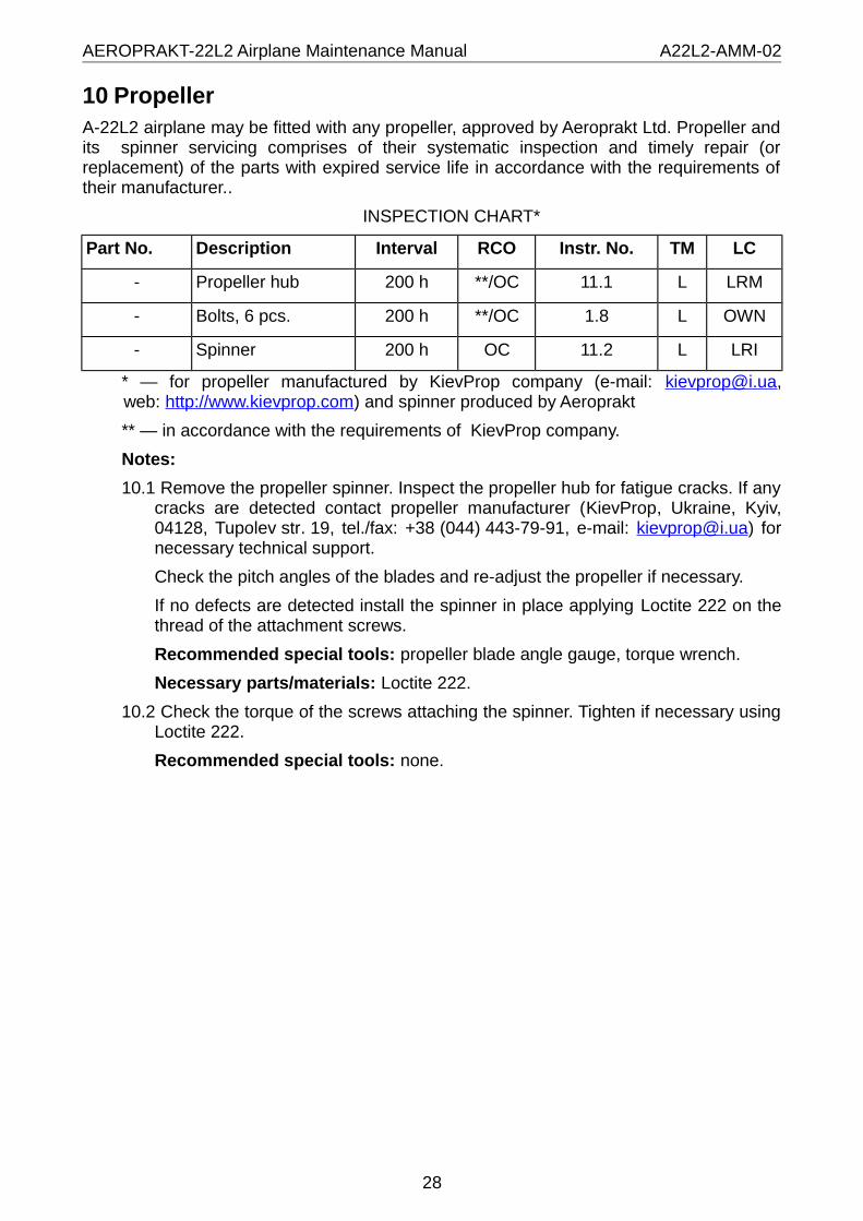
10 PropellerA-22L2 airplane may be fitted with any propeller, approved by Aeroprakt Ltd. Propeller and its spinner servicing comprises of their systematic inspection and timely repair (or replacement) of the parts with expired service life in accordance with the requirements of their manufacturer..
INSPECTION CHART*
Part No. Description Interval RCO Instr. No. TM LC
- Propeller hub 200 h **/OC 11.1 L LRM
- Bolts, 6 pcs. 200 h **/OC 1.8 L OWN
- Spinner 200 h OC 11.2 L LRI
* — for propeller manufactured by KievProp company (e-mail: [email protected], web: http://www.kievprop.com) and spinner produced by Aeroprakt
** — in accordance with the requirements of KievProp company.
Notes:
10.1 Remove the propeller spinner. Inspect the propeller hub for fatigue cracks. If any cracks are detected contact propeller manufacturer (KievProp, Ukraine, Kyiv, 04128, Tupolev str. 19, tel./fax: +38 (044) 443-79-91, e-mail: [email protected]) for necessary technical support.
Check the pitch angles of the blades and re-adjust the propeller if necessary.
If no defects are detected install the spinner in place applying Loctite 222 on the thread of the attachment screws.
Recommended special tools: propeller blade angle gauge, torque wrench.
Necessary parts/materials: Loctite 222.
10.2 Check the torque of the screws attaching the spinner. Tighten if necessary using Loctite 222.
Recommended special tools: none.
28

AEROPRAKT-22L2 Airplane Maintenance Manual A22L2-AMM-02
11 Airplane control systemThe airplane control system consists of control systems of ailerons, elevator, elevator trim tab, and aileron drooping mechanism. Control systems of ailerons and elevator may be with either yokes or central stick. The control system of elevator trim tab may be either mechanical or electrical one.
Control system linkage for ailerons and elevator is rigid, and for the elevator and its trim tab it is made of cables.
Servicing of the airplane control system comprises of its systematic inspection, lubrication, detection of worn components, repair and timely replacement of the parts with the expired service life.
The control system must operate smoothly without jamming and significant play. The clearances between the movable parts of the control system and fixed structural elements must be at least 5 mm (0.2 in).
Main components of the system to be checked are:
- fabric covering of the control surfaces;- spherical bearings;- slide bearing;- fairleads;- cables;- pulleys;- fasteners.
The fabric covering must be inspected for damage and delamination from the framework of the control surfaces. Minor ruptures (less than 50 mm or 2 in) may be repaired by covering them with ORACAL permanent sticking film. In case of significant damage and delamination of the fabric covering from the framework contact aircraft manufacturer for the required technical support.
The spherical bearings are installed in hinge brackets of the control surfaces, in control rods and control system supports. The used hinges do not require any servicing. Their wear must be checked by their radial and axial play. Maximum radial play is 0.25 mm (0.01 in) maximum axial play – 0.5 mm (0.02 in). If the play is exceeding the above specified values contact the manufacturer for the required technical support.
Slide bearings are used in hinge brackets of the control surfaces and in control system supports. They consist of a sleeve and an axle. The sleeves used in this airplane are either off bronze or off steel. In the hinge brackets the sleeve is press-fitted into the bracket, fixed to the airframe structure, and the axle is component of the movable control surface. In the Cardan joints and in the control system supports the sleeves are installed both in fixed and movable parts, and bolts (or pins) are used as axles. Slide bearing wear must be checked by the radial play. The maximum radial play is 0.5 mm (0.02 in). If the play exceeds the specified value contact the manufacturer for the required technical support.
Slide bearings require periodic lubrication. They may be lubricated by any grease for bearings every 200 hours or on condition.
The fairleads are used in the control systems of rudder and elevator trim tab and serve to retain the cables. The fairleads are made of textolite. The fairleads wear must be checked by the depth of the slot created due to cable friction against them. The slot depth must not exceed double diameter of the cable. If the wear is exceeding the specified value contact the manufacturer for the required technical support.
29

AEROPRAKT-22L2 Airplane Maintenance Manual A22L2-AMM-02
The cables are used in the control systems of the rudder and elevator trim tab. The cables must be inspected for broken wires. Special attention must be paid to the areas where cables pass through the fairleads, pulleys and to the cable terminations. If broken cable wires are found than the cable must be replaced. Contact the manufacturer for the required technical support.
Pulleys are used in the control system of rudder. They do not require any servicing. The pulley must rotate without jamming and play. If jamming or play appears the pulley must be replaced.
WARNING! When servicing the control system avoid over-tightening the bolts serving as slide bearing axles. The tightening must eliminate the axial play however it must allow unrestricted motion of the movable part of the joint. All bolts, nuts (except for self-locking ones), pins, turnbuckles must be locked reliably.
Adjustment of the aileron control system is achieved by changing the length of the vertical and diagonal control rods.
Adjustment of the elevator control system is achieved by changing the length of the aft control rod.
WARNING! To increase the length of a control rod, loosen the locking nut and screw the rod end OUT (all treads are right-hand!), to reduce the length – screw it DOWN. After adjusting the rod length tighten the locking nut applying the Loctite 222 on the thread.
Adjustment of the rudder control system is achieved using the turnbuckles of the rudder control cables.
Adjustment of the elevator trim tab control system is achieved by fixing the control cable of the trim tab with a screw in the control arm of the tab at a proper setting.
WARNING! Do not cut the excessive length of the cable beyond the control arm of the tab. This portion is required for passing the cable through its sheath in the elevator when re-attaching the elevator to the stabilizer. After adjusting the cable length coil its free end carefully and secure it to the trim tab control arm with a plastic binder but in a manner that does not hamper the tab deflection while it is being controlled.
Adjustment of the control system must ensure the deflection angles of the control surfaces specified in the "Pilot Operating Handbook A-22L2".
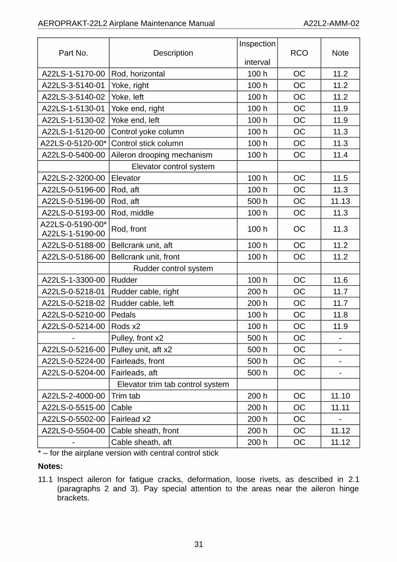
INSPECTION CHART
Part No. DescriptionInspection
intervalRCO Note
Aileron control system
A22LS-1-3700-01 Aileron, right 100 h OC 11.1
A22LS-1-3700-02 Aileron, left 100 h OC 11.1
A22LS-0-5165-00 Cardan ring x2 100 h OC 11.2
A22LS-0-5160-01 Aileron shaft, right 100 h OC 11.2
A22LS-0-5160-02 Aileron shaft, left 100 h OC 11.2
A22LS-0-5175-00 Rod, vertical х2 100 h OC 11.3
A22LS-0-5150-00* Roll shaft 100 h OC 11.3
A22LS-1-5150-00 Roll shaft 100 h OC 11.3
A22LS-1-5172-00 Rod, diagonal 100 h OC 11.2
30
AEROPRAKT-22L2 Airplane Maintenance Manual A22L2-AMM-02
Part No. DescriptionInspection
intervalRCO Note
A22LS-1-5170-00 Rod, horizontal 100 h OC 11.2
A22LS-3-5140-01 Yoke, right 100 h OC 11.2
A22LS-3-5140-02 Yoke, left 100 h OC 11.2
A22LS-1-5130-01 Yoke end, right 100 h OC 11.9
A22LS-1-5130-02 Yoke end, left 100 h OC 11.9
A22LS-1-5120-00 Control yoke column 100 h OC 11.3
A22LS-0-5120-00* Control stick column 100 h OC 11.3
A22LS-0-5400-00 Aileron drooping mechanism 100 h OC 11.4
Elevator control system
A22LS-2-3200-00 Elevator 100 h OC 11.5
A22LS-0-5196-00 Rod, aft 100 h OC 11.3
A22LS-0-5196-00 Rod, aft 500 h OC 11.13
A22LS-0-5193-00 Rod, middle 100 h OC 11.3
A22LS-0-5190-00* A22LS-1-5190-00
Rod, front 100 h OC 11.3
A22LS-0-5188-00 Bellcrank unit, aft 100 h OC 11.2
A22LS-0-5186-00 Bellcrank unit, front 100 h OC 11.2
Rudder control system
A22LS-1-3300-00 Rudder 100 h OC 11.6
A22LS-0-5218-01 Rudder cable, right 200 h OC 11.7
A22LS-0-5218-02 Rudder cable, left 200 h OC 11.7
A22LS-0-5210-00 Pedals 100 h OC 11.8
A22LS-0-5214-00 Rods х2 100 h OC 11.9
- Pulley, front х2 500 h OC -
A22LS-0-5216-00 Pulley unit, aft х2 500 h OC -
A22LS-0-5224-00 Fairleads, front 500 h OC -
A22LS-0-5204-00 Fairleads, aft 500 h OC -
Elevator trim tab control system
A22LS-2-4000-00 Trim tab 200 h OC 11.10
A22LS-0-5515-00 Cable 200 h OC 11.11
A22LS-0-5502-00 Fairlead х2 200 h OC -
A22LS-0-5504-00 Cable sheath, front 200 h OC 11.12
- Cable sheath, aft 200 h OC 11.12* – for the airplane version with central control stick
Notes:
11.1 Inspect aileron for fatigue cracks, deformation, loose rivets, as described in 2.1 (paragraphs 2 and 3). Pay special attention to the areas near the aileron hinge brackets.
31

AEROPRAKT-22L2 Airplane Maintenance Manual A22L2-AMM-02
Check the play in the aileron hinge brackets and Cardan joint. Grease the slide bearings if necessary.
Check tightness and locking of the nut of the aileron root hinge bracket.
Inspect the fabric covering as described in the beginning of this section.
11.2 Check tightness and locking of the nuts and play in hinged joints. Torque for tightening the nuts on bolts joining the cardan rings of the aileron control system – 2 Nm. Grease the slide bearings if necessary.
11.3 Check tightness and locking of the nuts and play in hinged joints.
Inspect the riveted joints for loose rivets as described in 2.1. If loose rivets are detected contact the manufacturer for the required technical support.
11.4 Remove the housing of the aileron drooping mechanism after extending the flaps to 20°. Check tightness and locking of the nuts and play in hinged joints. Grease the slide bearings if necessary.
11.5 Inspect the elevator for fatigue cracks, deformation, loose rivets, as described in 2.1 (paragraphs 2 and 3). Pay special attention to the areas near the elevator control arm and hinge brackets.
Check play in the elevator hinges. Grease the slide bearings if necessary.
Check tightness and locking of the nuts on the center hinge and control rod attachment.
Inspect the fabric covering as described in the beginning of this section.
11.6 Inspect the rudder for fatigue cracks, deformation, loose rivets, as described in 2.1 (paragraphs 2 and 3). Pay special attention to the areas near the rudder control arms and hinge brackets.
Check play in the rudder hinges. Grease the slide bearings if necessary.
Check tightness and locking of the lower hinge nut and locking of the attachment pins of the control cables.
Inspect the fabric covering as described in the beginning of this section.
11.7 Inspect the cable for wear in the areas where it passes through fairleads and pulleys. If any cable wire is broken the cable must be replaced. Contact the manufacturer for the required technical support.
Check the cable tension. To do that, apply 30 N (6.7 lb) side load towards the other cable of in the middle of the cable portion between the pulley supports behind the luggage container. The cable sag must be equal to 50±5 mm (2±0.2 in). If necessary adjust the cable tension using the turnbuckles. Lock the turnbuckles with safety wire after that.
11.8 Inspect the pedals for fatigue cracks and deformation. Pay special attention to the weld seams. In case of detecting cracks contact the manufacturer for the required technical support.
Check tightness and locking of the nut of the nose wheel control rods.
Check locking of the pins and pedal supports.
Check play in the supports and hinged joints. Grease slide bearings if necessary.
11.9 Check tightness and locking of the nuts and play in hinged joints. Grease the slide bearings if necessary.
32

AEROPRAKT-22L2 Airplane Maintenance Manual A22L2-AMM-02
11.10 Check the trim tab fasteners for corrosion. Replace corroded fasteners. Grease slide bearings if necessary.
11.11In airplane version with mechanical control system of the elevator trim tab remove the handles from the control levers of throttle, trim tab, brakes and horizontal panel. Inspect the cable for wear in the areas where it passes fairleads, cable sheath and near its attachment to the control lever and trim tab control arm.
In airplane version with electromechanical control system of the elevator trim tab inspect the cable in the areas where it passes fairleads, sheath and near its attachment to the control arm of the trim tab.
If any cable wire is broken the cable must be replaced. Contact the manufacturer for the required technical support.
After inspection assemble everything in the reversed order.
11.12 Inspect the cable sheath for kinks and damage. A damaged portion of the cable sheath may be repaired by setting over it a piece of thermoshrinkable tube.
If significant kinks in cable sheath were detected that hamper the cable motion, the sheath must be replaced. After replacement or repair of the cable sheath the trim tab control system must be re-adjusted.
11.13 Disconnect the front and rear ends of the aft rod. Lift the elevator up and take out the rod from fuselage. Inspect the area of rod contact with the supporting rollers. If the wear spot is wider than 8 mm replace the rod.
33

AEROPRAKT-22L2 Airplane Maintenance Manual A22L2-AMM-02
12 Electrical systemThe major components of the electrical system of A-22L2 airplane are: battery (12 V, minimum 16 Ah), starter relay, rectifier-regulator, condenser (22000 µF, 25 V), warning light (12 V, 2 W), master switch, ignition and consumer switches, fuse block, electric harness, fuel level senders and indicators and analog engine instruments. Optionally the airplane may be also equipped with ground switch, landing light and miscellaneous consumers.
The battery is located on the left side behind the frame No. 3. The starter relay, rectifier-regulator and condenser are located on the left side of the firewall. The switches, fuses, and fuel level indicators – on the lower part of the instrument panel. The warning light – on the left side of the instrument panel. Fuel level sensors are installed in the fuel tanks. The landing light – on the lower part of the engine mount.
The electrical system arrangement complies with the requirements of the "Installation manual of Rotax-912 aircraft engine".
WARNING! Checking the electrical system components belonging to the engine electrical system (rectifier-regulator, condenser, engine instruments) shall be performed in accordance with the current documentation of Rotax company on operation and maintenance of Rotax-912 engine.
Depending to airplane configuration, the electrical system may include miscellaneous consumers (radio, transponder, engine instruments, navigation lights, etc.). Servicing those consumers shall be performed in accordance with the current documentation on their operation and maintenance of their respective manufacturers.
The electrical system of the airplane requires minimum servicing. The main problems that may arise in the electrical system is corrosion of contacts and chaffing of wires.
To prevent oxidation of the connectors and terminals they must be covered with some Lithium-based grease.
To minimize the probability of chaffing and prevent breaking (or short circuit) of wiring the reliable fixation (binding) of harnesses must be ensured. Special attention must be paid to the areas where wiring is located close to the movable parts of airplane. To fix the wiring use plastic binders (cable ties).
INSPECTION CHART
Part No. Description Inspection interval RCO Note
- Battery 100 h OC 12.1
See Rotax P/N Starter relay 100 h OC 12.2
- Power cables 100 h OC 12.3
See Rotax P/N Rectifier-regulator 100 h OC 12.4
- Condenser 100 h OC 12.4
- Warning light 100 h OC -
- Master switch 100 h OC -
- Ignition switch х2 100 h OC -
- Consumer switches 100 h OC -
- Fuse block 100 h OC 12.5
- Fuses 100 h OC 12.5
- Fuel level sensor х2 200 h OC 12.6
34

AEROPRAKT-22L2 Airplane Maintenance Manual A22L2-AMM-02
Part No. Description Inspection interval RCO Note
- Fuel level indicator х2 200 h OC 12.6
- Landing light 100 h OC 12.7
- Engine instruments 100 h OC 12.8
- Main harness 100 h OC 12.9
- Harness for engine instruments 100 h OC 12.10
Notes:
12.1 Replace the battery when it does not charge or discharge properly. Keep the battery terminals clean; do not allow corrosion to appear on its surfaces.
12.2 Inspect terminals and connector of the starter relay for corrosion and clean them if necessary.
WARNING! To prevent starter from inadvertent engagement or short circuit switch OFF the ground switch (if installed) or disconnect one of the power cables from the battery.
Make sure the relay and cables connected to it are attached reliably.
12.3 Inspect the terminals of the power cables connecting the battery to the starter and airplane ground for corrosion and damage at cable terminations. If necessary clean the terminals from corrosion. Bad contact will cause cable overheating and difficult engine start.
If the cables are damaged, contact manufacturer for the required technical support.
12.4 Inspect terminals and connectors for corrosion and clean if necessary.
12.5 Remove the fuse block cover. Take out the fuses and inspect their sockets. If corrosion is detected the fuses and sockets must be cleaned. After servicing put in place the fuses and fuse block cover.
12.6 Verify correctness of the fuel level indicators’ readings. For that do the following:
- close the fuel valves;- fill a fuel tank fully (45 l or 11.9 US gal);- switch ON the master switch;- open the valve of the full fuel tank;- drain fuel through the drain valve and compare the fuel level indicator readings
against the fuel remaining in the tank:45 l (11.9 US gal) – «4/4»22 l (5.8 US gal) – «1/2»6 l (1.6 US gal) – “reserve fuel remains” light ignites1 l (0.3 US gal) – «0»;
WARNING! Be careful while working with the fuel system, the fuel is highly fire-hazardous.
- switch OFF the master switch;- perform the check of the other fuel level sensor and indicator;
If the “reserve fuel remains” light does not ignite it must be replaced. If after replacement the light still does not ignite, contact the manufacturer for the required technical support.
If at «4/4» and «1/2» readings the remaining fuel differs from the reading for more than 5 l (1.3 US gal) and the fuel remaining at ignition of “reserve fuel remains” light
35

AEROPRAKT-22L2 Airplane Maintenance Manual A22L2-AMM-02
differs for more than 2 l (0.5 US gal), contact the manufacturer for the required technical support.
12.7 Remove top and bottom cowling. Check torque of the nut attaching the landing light and tighten it if necessary.
Check landing light functioning and replace the lamp if necessary.
12.8 Inspect the terminals and connectors of the sensors for corrosion and clean if necessary.
12.9 Remove top cowling. Inspect the electrical harness for damage (chaffing, broken wires). Restore damaged insulation by setting a piece of thermoshrinkable tube over it. Connect broken wires by soldering with following insulation of the soldered areas with thermoshrinkable tube.
Special attention must be paid to the areas where harness comes through the firewall and near the airbox.
After every 1000 hours of flight time the harness must be freed from its fixation inside the fuselage (cut the plastic binder fixing the harness and preventing the harness extraction and inspection) and moved carefully to 10-15 mm (0.4-0.6 in) away from its place for inspection. The abraded insulation of wires detected during the inspection must be restored by covering it with insulating tape or thermoshrinkable tubing. After that put the harness in its place and fix with plastic cable ties.
Check the integrity of the protective rubber insert in the area where harness passes close to the airbox and replace the insert if necessary.
12.10 Remove the top cowling. Inspect the electrical harness for damage (chaffing, broken wires). Restore damaged insulation by setting a piece of thermoshrinkable tube over it. Connect broken wires by soldering with following insulation of the soldered areas with thermoshrinkable tube.
Inspect the terminals and connectors of the sensors for corrosion and clean if necessary.
36

AEROPRAKT-22L2 Airplane Maintenance Manual A22L2-AMM-02
13 Cockpit heating systemCockpit heating system of A-22L2 airplane consists of warm air scoop (located behind the engine cooling system radiator), warm air duct (flexible corrugated hose), warm air shutter housing (attached to the firewall inside the engine compartment of the left side) and warm air shutter actuator. The control handle of the actuator is located on the left side of the instrument panel. The shutter actuator comprises a thick wire and a flexible conduit. The warm air duct connects the warm air scoop to the warm air shutter housing. The duct is attached to the scoop and housing with screw clamps. In flight some portion of the air cooling the engine radiator is forced into the warm air scoop and then is going via the duct to the shutter housing and (when the cockpit heating handle is in the “ON” position) through the hole in the firewall into the cockpit. When the cockpit heating handle is set to “OFF” position, the shutter closes the hole in the firewall and the warm air is not getting into the cockpit but is released into the engine compartment via an opening in the shutter housing.
INSPECTION CHART
Part No. Description Interval RCO Note
A22-1-6520-00 Warm air scoop 100 h OC 13.1
A22-1-6509-00 Warm air shutter housing 100 h OC13.2
A22-1-6501-00 Warm air shutter 100 h OC
A22-0-6514-00 Warm air duct 50 h OC 13.3
A22LS-0-6535-00 Warm air shutter actuator 100 h OC 13.4
Notes:
13.1 Remove the top and bottom engine cowling. Inspect the warm air scoop for damage. If it is damaged, remove it from its place, clean the damaged area with sand paper and apply a patch of fiberglass cloth impregnated with epoxy adhesive.
13.2 Remove the top engine cowling. Inspect the warm air shutter housing and shutter for damage. Check if the shutter closes and opens fully and moves freely and without jamming. If the shutter or housing is damaged so that the shutter is not functioning properly, replace the shutter or housing.
13.3 Remove the top and bottom engine cowling. Inspect the warm air duct for damage and secure attachment to air scoop and shutter housing. If the hose is damaged (i.e. has holes or ruptures) replace it. If the actuator has kinks or other damage hampering the shutter control, replace the actuator.
13.4 Remove the top engine cowling. Check the condition of the air shutter actuator in the engine compartment and in the cockpit (remove the instrument panel if necessary).
37
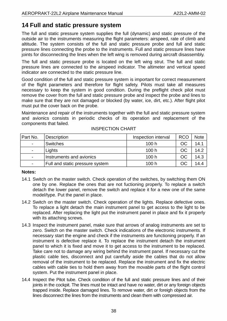
AEROPRAKT-22L2 Airplane Maintenance Manual A22L2-AMM-02
14 Full and static pressure systemThe full and static pressure system supplies the full (dynamic) and static pressure of the outside air to the instruments measuring the flight parameters: airspeed, rate of climb and altitude. The system consists of the full and static pressure probe and full and static pressure lines connecting the probe to the instruments. Full and static pressure lines have joints for disconnecting the lines when the left wing is removed during aircraft disassembly.
The full and static pressure probe is located on the left wing strut. The full and static pressure lines are connected to the airspeed indicator. The altimeter and vertical speed indicator are connected to the static pressure line.
Good condition of the full and static pressure system is important for correct measurement of the flight parameters and therefore for flight safety. Pilots must take all measures necessary to keep the system in good condition. During the preflight check pilot must remove the cover from the full and static pressure probe and inspect the probe and lines to make sure that they are not damaged or blocked (by water, ice, dirt, etc.). After flight pilot must put the cover back on the probe.
Maintenance and repair of the instruments together with the full and static pressure system and avionics consists in periodic checks of its operation and replacement of the components that failed.
INSPECTION CHART
Part No. Description Inspection interval RCO Note
- Switches 100 h OC 14.1
- Lights 100 h OC 14.2
- Instruments and avionics 100 h OC 14.3
- Full and static pressure system 100 h OC 14.4
Notes:
14.1 Switch on the master switch. Check operation of the switches, by switching them ON one by one. Replace the ones that are not fuctioning properly. To replace a switch detach the lower panel, remove the switch and replace it for a new one of the same model/type. Put the panel in place.
14.2 Switch on the master switch. Check operation of the lights. Replace defective ones. To replace a light detach the main instrument panel to get access to the light to be replaced. After replacing the light put the instrument panel in place and fix it properly with its attaching screws.
14.3 Inspect the instrument panel, make sure that arrows of analog instruments are set to zero. Switch on the master switch. Check indications of the electronic instruments. If necessary start the engine and check if the instruments are functioning properly. If an instrument is defective replace it. To replace the instrument detach the instrument panel to which it is fixed and move it to get access to the instrument to be replaced. Take care not to damage any wiring behind the instrument panel. If necessary cut the plastic cable ties, disconnect and put carefully aside the cables that do not allow removal of the instrument to be replaced. Replace the instrument and fix the electric cables with cable ties to hold them away from the movable parts of the flight control system. Put the instrument panel in place.
14.4 Inspect the Pitot tube. Check condition of the full and static pressure lines and of their joints in the cockpit. The lines must be intact and have no water, dirt or any foreign objects trapped inside. Replace damaged lines. To remove water, dirt or foreigh objects from the lines disconnect the lines from the instruments and clean them with compressed air.
38

AEROPRAKT-22L2 Airplane Maintenance Manual A22L2-AMM-02
15 Pilot seats and harness beltsThe pilot seats of A-22L2 airplane are adjustable (they have 2 fixed settings) and consist of an aluminum framework and a cushion.
The harness system is of four-point type. It consists of two sets of harness belts.
INSPECTION CHART
Part No. Description Inspection interval RCO Note
А22LS-0-8010-00 Pilot seat framework х2 100 h OC 15.1
А22LS-0-8020-00 Pilot seat cushion х2 100 h OC 15.2
А22LS-3-7550-00 Harness belts set х2 100 h OC 15.3
Notes:
15.1 Remove the cushions from the seat framework. Inspect the framework for the fatigue cracks and loose rivets.
Upon detecting cracks with length less than 10 mm (0.4 in) stop the crack propagation by drilling carefully a Ø3 mm (0.12 in) hole at its end. If the crack is longer than 10 mm (0.4 in), the framework must be replaced (repaired). To obtain the instructions on repair of the framework contact the manufacturer.
If loose rivets are detected they must be replaced. For that do as follows:
- remove the pilot seat framework;- remove the cores from the loose pop-rivets;- drill out the rivets with a Ø3 mm (0.12 in) drill;- install new Ø3×6 rivets;- install the seat framework in place.
If no defects are detected install the seats back. Apply Loctite 222 on the thread of the attaching bolts.
15.2 Inspect the seat cushions for damage of the upholstery and repair it if necessary.
15.3 Check functioning of the harness belts’ locks. For that apply a 300 N (67 lb) tension to the waist belts. The lock must not unlock spontaneously under the load. Otherwise the lock must be replaced.
Inspect the belts for damage (cuts, chaffing). Upon detecting any damage contact the manufacturer for the required technical support.
39

AEROPRAKT-22L2 Airplane Maintenance Manual A22L2-AMM-02
16 Cockpit doorsThe cockpit doors are made in form of a PVC glass on a riveted metal framework. The doors may be fitted optionally with locks. The doors are retained in their open position with a gas strut. The forward part of each door is fitted with aventillation air scoop.
The doors can be removed quickly. To remove the doors do the following:
- while holding the door open detach the gas strut from fuselage (remove the securing clamp and move the strut away);
- while holding the door outside remove the pins from the door hinges (first the aft than the front one);
- remove the door.
To install the door repeat above actions in the reversed order.
INSPECTION CHART
Part No. Description Inspection interval RCO Note
A22LS-0-1350-01 Door, right 100 h OC 16.1
A22LS-0-1350-02 Door, left 100 h OC 16.1
- Gas strut х2 100 h OC 16.2
Notes:
16.1 Inspect the door glass as described in 2.2.
Inspect and if necessary replace the door sealing. To do that carefully clean the door from the old sealing and fix the new one.
Inspect the framework, hinges and fasteners of the door for fatigue cracks, damage and loose rivets, as described in 2.1 (paragraph 2 and 3).
16.2 Check the functioning of the gas strut. Its cylinder rod must move smoothly and without jamming. The gas strut must retain the door in open position. If not than the gas strut must be replaced.
40

AEROPRAKT-22L2 Airplane Maintenance Manual A22L2-AMM-02
17 Recovery systemA-22L2 airplane can optionally be equipped with a parachute recovery system for the maximum take-off weight of 600 kg (1320 lb).
The recovery system is installed on the right side behind the luggage container. The system actuation handle is installed on the panel between the pilot seats.
The system suspension cables are fixed to fuselage in three locations (at firewall and near the rear attachment points of the wings).
System servicing must be performed in accordance with the current documentation of the recovery system manufacturer.
WARNING! Before any servicing of the system install the safety pin into its actuation mechanism.
INSPECTION CHART
Part No. Description Inspection interval RCO Note
- Container with parachute * -
- Actuation handle with cable * -
A22LS-5-7010-00 Suspension cable, front 500 h OC 17.1
A22LS-5-7020-01 Suspension cable, right 500 h OC 17.1
A22LS-5-7020-02 Suspension cable, left 500 h OC 17.1
* see Maintenance Manual for respective recovery system
Notes:
17.1 Check attachment of the suspension cables to the parachute lanyard and to fuselage structure. If necessary, replace the plastic binders fixing the cables.
41

AEROPRAKT-22L2 Airplane Maintenance Manual A22L2-AMM-02
18 Glider and banner towing systemA-22L2 airplane can be optionally equipped with E 85 tow release manufactured by Tost Flugzeuggerätebau company (http://www.tost.de) for towing of gliders or banners.
The tow release is attached to the tail fuselage on a special fitting. The tow release can be acuated by pulling the tow release handle (located near the flap extension lever) connected to the tow release lever with a control cable.
INSPECTION CHART
Part No. DescriptionInspection
intervalRCO Note
A22LS-0-6725-00 Tow release control cable 100 h OC 16.1
014000 Tow release 100 h 2000 starts / 4 years 16.2
Instructions:
18.1 Inspect the tow release control cable from the release handle to the tow release lever. The cable must be is intact and free from corrosion (otherwise the cable must be replaced).
Check the tow release force on the release handle. If release the force has increased too much – check condition of the tow release control cable and grease the cable near its fearleads.
18.2 Clean, lubricate and check for proper operation the tow release. The tow release release must be performed without jamming. If the jamming occurs it must be eliminated or release must be replaced for the one identical to that installed on the airplane.
NOTE: Releases are approved aeronautical parts. Their safety and operating life can be assured only by observing the maintenance intervals prescribed by EASA. Releases must be returned to the manufacturer for complete reconditioning after 10000 operations (approx. 2000 starts). Manufacturer recommends the general overhaul after 4 years. Due to environmental influence releases can corrode or become stiff and thus fail during operation.
42
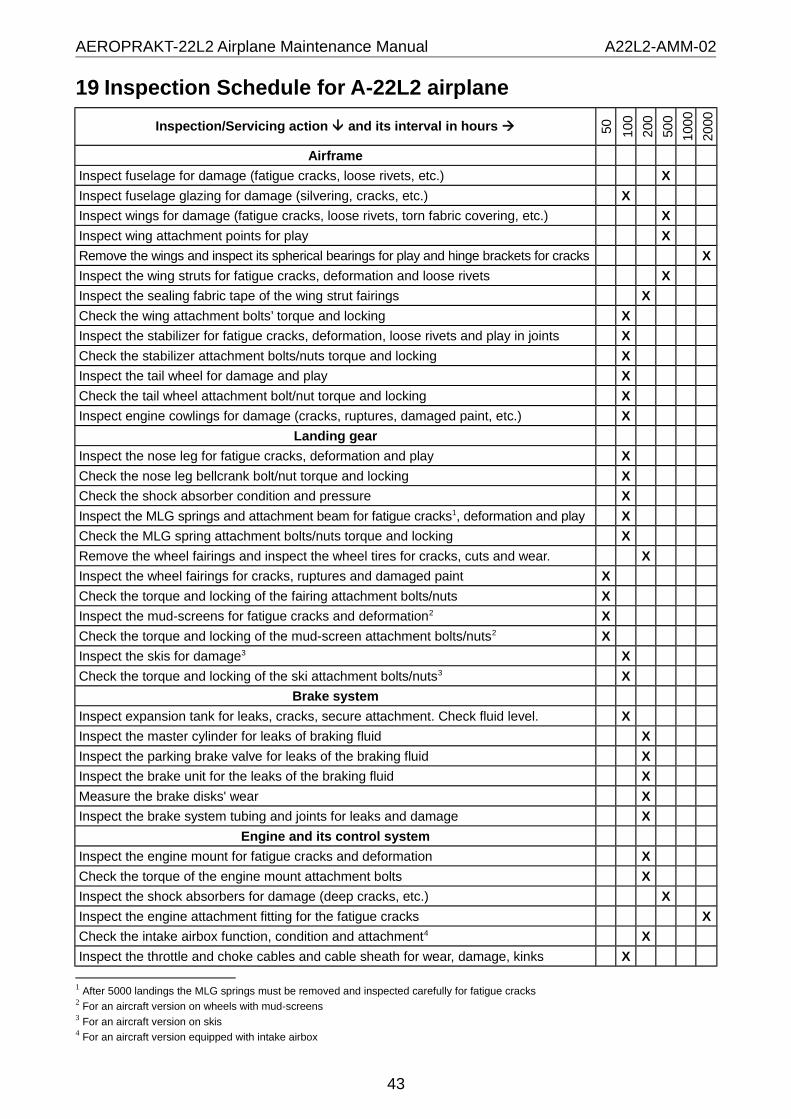
AEROPRAKT-22L2 Airplane Maintenance Manual A22L2-AMM-02
19 Inspection Schedule for A-22L2 airplane
Inspection/Servicing action and its interval in hours 50 100
200
500
100
0
2000
Airframe
Inspect fuselage for damage (fatigue cracks, loose rivets, etc.) X
Inspect fuselage glazing for damage (silvering, cracks, etc.) X
Inspect wings for damage (fatigue cracks, loose rivets, torn fabric covering, etc.) X
Inspect wing attachment points for play X
Remove the wings and inspect its spherical bearings for play and hinge brackets for cracks X
Inspect the wing struts for fatigue cracks, deformation and loose rivets X
Inspect the sealing fabric tape of the wing strut fairings X
Check the wing attachment bolts’ torque and locking X
Inspect the stabilizer for fatigue cracks, deformation, loose rivets and play in joints X
Check the stabilizer attachment bolts/nuts torque and locking X
Inspect the tail wheel for damage and play X
Check the tail wheel attachment bolt/nut torque and locking X
Inspect engine cowlings for damage (cracks, ruptures, damaged paint, etc.) X
Landing gear
Inspect the nose leg for fatigue cracks, deformation and play X
Check the nose leg bellcrank bolt/nut torque and locking X
Check the shock absorber condition and pressure X
Inspect the MLG springs and attachment beam for fatigue cracks1, deformation and play X
Check the MLG spring attachment bolts/nuts torque and locking X
Remove the wheel fairings and inspect the wheel tires for cracks, cuts and wear. X
Inspect the wheel fairings for cracks, ruptures and damaged paint X
Check the torque and locking of the fairing attachment bolts/nuts X
Inspect the mud-screens for fatigue cracks and deformation2 X
Check the torque and locking of the mud-screen attachment bolts/nuts2 X
Inspect the skis for damage3 X
Check the torque and locking of the ski attachment bolts/nuts3 X
Brake system
Inspect expansion tank for leaks, cracks, secure attachment. Check fluid level. X
Inspect the master cylinder for leaks of braking fluid X
Inspect the parking brake valve for leaks of the braking fluid X
Inspect the brake unit for the leaks of the braking fluid X
Measure the brake disks' wear X
Inspect the brake system tubing and joints for leaks and damage X
Engine and its control system
Inspect the engine mount for fatigue cracks and deformation X
Check the torque of the engine mount attachment bolts X
Inspect the shock absorbers for damage (deep cracks, etc.) X
Inspect the engine attachment fitting for the fatigue cracks X
Check the intake airbox function, condition and attachment4 X
Inspect the throttle and choke cables and cable sheath for wear, damage, kinks X
1 After 5000 landings the MLG springs must be removed and inspected carefully for fatigue cracks2 For an aircraft version on wheels with mud-screens3 For an aircraft version on skis4 For an aircraft version equipped with intake airbox
43

AEROPRAKT-22L2 Airplane Maintenance Manual A22L2-AMM-02
Inspection/Servicing action and its interval in hours 50 100
200
500
100
0
2000
Check the torque of the throttle lever bolt (axle) X
Cooling system
Check the radiator clamps integrity and torque X
Inspect the overflow tank for leaks of coolant, cracks; check coolant level X
Inspect lines for leaks, damage (chaffing, cracks), untight joints X
Check torque of the water inlet elbow hose clamps, tighten if necessary X
Lubrication system
Inspect the oil tank plug for oil leaks; verify vent line is intact and secured X
Inspect lines for leaks and damage (chaffing, cracks), untight joints X
Fuel system
Remove fuel tanks and inspect them for fuel leaks and damage X
Inspect the shut-off and drain fuel valves for leaks of fuel X
Check condition and replace fuel filter (if necessary) X
Inspect fuel lines for leaks, damage (chaffing, cracks), untight joints X
Check condition and replace fuel lines (if necessary) X
Exhaust system
Inspect exhaust pipes and muffler for cracks X
Verify attachment springs are intact X
Propeller
Inspect propeller hub for fatigue cracks; check pitch angles X
Check torque and locking of the propeller bolts/nuts X
Check torque of the spinner bolts X
Airplane control system
Inspect control surfaces for fatigue cracks, deformation, loose rivets, torn fabric X
Check the play in the hinges of control surfaces/linkages X
Check tightness/locking of the nuts of control surfaces/linkages X
Check tightness/locking of the nuts and play in hinges of control rods/shafts X
Extend flaps and inspect flap extension (play in hinges, nuts tightness/locking) X
Grease the slide bearings of all control surfaces/linkages (where necessary) X
Inspect rudder control cables for wear, check cable tension X
Inspect rudder pedals for fatigue cracks and deformation X
Check condition of the control cable pulleys and fairleads X
Check trim tab attachment bolts/nuts for corrosion, replace if necessary X
Inspect the trim tab control cables and sheath for damage (wear, kinks, etc.) X
Take out and inspect the aft rod for wear. Replace if necessary. X
Electrical system
Verify battery charges/discharges properly, otherwise replace X
Clean starter terminals and starter relay connector of corrosion, if any X
Verify starter relay and cables are connected and attached reliably X
Verify power cables have good contact with battery, starter and ground X
Clean rectifier-regulator and condenser terminals/connectors of corrosion, if any X
Check condition of electric switches and warning lights X
Clean fuse block terminals of corrosion, if any. Check fuses X
Verify correct function of the fuel level sensors/indicators (check readings) X
Check landing light function and attaching nut torque X
Clean engine sensors' terminals and connectors of corrosion, if any X
44

AEROPRAKT-22L2 Airplane Maintenance Manual A22L2-AMM-02
Inspection/Servicing action and its interval in hours 50 100
200
500
100
0
2000
Inspect electrical harness for damage (chaffing, broken wires, bad insulation) X
Pilot seats and harness belts
Inspect the seats framework for the fatigue cracks and loose rivets X
Inspect the seat cushions upholstery for damage X
Verify harness belts’ locks function properly X
Cockpit doors
Inspect door glass, framework and sealing for damage X
Verify the gas struts function properly X
Recovery system
Check attachment of the suspension cables to fuselage and parachute lanyard X
Glider and banner towing system
Inspect the tow release control cable for damage/corrosion. Replace if necessary. X
Clean, lubricate and check the tow release for operation. Replace if necessary.5 X
5 Tow release must be returned to the manufacturer for complete reconditioning after 10000 operations (approx. 2000 starts). Manufacturer recommends the general overhaul after 4 years.
45