Embed Size (px)
Citation preview
Aeroplane and Rotorcraft Simulator Manual
TP 9685E
Revision 2 - January 1998
Aussi disponible en français
Foreword
This manual provides: 1. Procedures for the approval of synthetic flight training devices; 2. A classification system for synthetic flight training devices; 3. Minimum standards for synthetic flight training devices; 4. Procedures for initial and recurrent evaluation of synthetic flight training devices; 5. Procedures for using the Simulator Component Inoperative Guide (SCIG); 6. Information on the approval and use of foreign-owned simulators and flight
training devices; and 7. Training and checking credits for aeroplane and rotorcraft simulators and training
devices. This manual is issued pursuant to the Canadian Aviation Regulations prescribing the requirements to be met for the use of synthetic flight training devices in an approved flight crew member training program. M.R. Preuss Acting Director Commercial & Business Aviation

Record of Amendments
Amendment No. Date Pages Affected Date Entered Initials
Rev 2 Original January 1998

Aeroplane And Rotorcraft Simulator Manual Revision 2 - January 1998
Table of Contents Chapter 1 - Introduction...........................................................................1-1 1.1 Definitions .................................................................................................................1-1 1.2 Applicability..............................................................................................................1-6 1.3 General Procedures ...................................................................................................1-7 Chapter 2 - Aeroplane Simulators............................................................2-1 2.1 Classification System.................................................................................................2-1 2.2 Simulator Evaluation Policy........................................................................................2-1 2.3 Initial or Upgrade Evaluations.....................................................................................2-3 2.4 Recurrent Evaluations ................................................................................................2-6 2.5 Special Evaluations ....................................................................................................2-7 2.6 Modification of Simulators .........................................................................................2-7 2.7 Continued Qualification Basis.....................................................................................2-7 2.8 Simulator Performance Degradations..........................................................................2-8 2.9 Simulator Validation Checks......................................................................................2-8 2.10 Maintenance..............................................................................................................2-9 Appendix 2-A - Aeroplane Simulator Standards .....................................................2-A-1 Appendix 2-B - Aeroplane Simulator Validation Tests............................................2-B-1 Appendix 2-C - Functions and Subjective Tests......................................................2-C-1 Appendix 2-D - Windshear Qualification.................................................................2-D-1 Chapter 3 - Rotorcraft Simulators ...........................................................3-1 3.1 Classification Systems................................................................................................3-1 3.2 Simulator Evaluation Program....................................................................................3-1 3.3 Initial Evaluations .......................................................................................................3-2 3.4 Recurrent Evaluations ................................................................................................3-4 3.5 Special Evaluations ....................................................................................................3-5 3.6 Modification of Simulators, Motion and Visual Systems..............................................3-5 3.7 Upgrading of Simulators, Motion and Visual Systems .................................................3-6 Appendix 3-A - Rotorcraft Simulator Standards .....................................................3-A-1 Appendix 3-B - Rotorcraft Simulator Validation Tests............................................3-B-1 Appendix 3-C - Functions and Subjective Tests......................................................3-C-1 Chapter 4 - Flight Training Devices (FTD) .............................................4-1 4.1 Classification System.................................................................................................4-1 4.2 Evaluation Policy.......................................................................................................4-1 4.3 Initial or Upgrade Evaluations.....................................................................................4-4 4.4 Recurrent Evaluations ................................................................................................4-7 4.5 Special Evaluations ....................................................................................................4-9 4.6 Modification of FTDs ................................................................................................4-9

Page ii Table of Contents
Revision 2 - January 1998 Aeroplane And Rotorcraft Simulator Manual
4.7 Qualification Basis .....................................................................................................4-9 4.8 Downgrade of an Aircraft Simulator to an Aircraft FTD..............................................4-10 4.9 Previously Approved FTDs .......................................................................................4-11 Appendix 4-A - Flight Training Device Standards ..................................................4-A-1 Appendix 4-B - Flight Training Device Validation Tests.........................................4-B-1 Appendix 4-C - Functions and Subjective Tests......................................................4-C-1 Chapter 5 - Simulator Component Inoperative Guide (SCIG)................ 5-1 5.1 Purpose.....................................................................................................................5-1 5.2 Application for Use of the SCIG................................................................................5-1 5.3 Procedures for Using the SCIG..................................................................................5-2 5.4 SCIG Description......................................................................................................5-2 Appendix 5-A - Simulator Component Inoperative Guide - Example.....................5-A-1 Chapter 6 - Simulator Approval Representative (SAR).......................... 6-1 6.1 Applicability..............................................................................................................6-1 6.2 Qualifications for SAR Appointment...........................................................................6-1 6.3 Application for Appointment ......................................................................................6-2 6.4 Approval of Appointment ..........................................................................................6-3 6.5 Validity of Appointment .............................................................................................6-3 6.6 Privileges of a SAR....................................................................................................6-3 6.7 Responsibilities of a SAR...........................................................................................6-4 6.8 Responsibilities of the Employer.................................................................................6-4 6.9 Retention of Records.................................................................................................6-5 6.10 SAR Guidelines.........................................................................................................6-5 Appendix 6-A - SAR Representative Guidelines ......................................................6-A-1 Chapter 7 - Use of Foreign Simulators and Training Devices ................ 7-1 Chapter 8 - Training and Checking Credits ............................................ 8-1 8.1 Purpose.....................................................................................................................8-1 8.2 Application of Credits................................................................................................8-1 Appendix 8-A - Flight Training Credits - Aeroplanes .............................................8-A-1 Appendix 8-B - Proficiency Check Credits - Aeroplanes.........................................8-B-1 Appendix 8-C - Flight Engineer/Second Officer Proficiency Check
Credits - Aeroplanes......................................................................8-C-1 Appendix 8-D - Flight Training and Checking Credits - Rotorcraft .......................8-D-1 Appendix 8-E - Proficiency Checking Credits - Rotorcraft.....................................8-E-1

Aeroplane And Rotorcraft Simulator Manual Revision 2 - January 1998
Chapter 1 Introduction 1.1 Definitions 1.1.1 In this document: Aeroplane F means a power-driven, heavier-than-air aircraft deriving its lift in flight from
aerodynamic reactions on surfaces that remain fixed under given conditions of flight. Aircraft F means any machine capable of deriving support in the atmosphere from the
reactions of the air. Aircraft Simulator F is a full size replica of a specific type or make, model and series aircraft
cockpit, including the assemblage of equipment and computer programs necessary to represent the aircraft in ground and flight operations, a visual system providing an out-of-the-cockpit view and a force cueing system that is in compliance with the standards as specified in this manual.
Approved Training Program F means a flight crew member training program approved by
the Minister pursuant to the Canadian Aviation Regulations. Approval of Simulator/Training Device F is issued by the Manager, Simulator Program and
documents the performance capability of the simulator/device to be used for flight training or checking credit.
Cockpit F for synthetic flight training device purposes, consists of all that space forward of a
cross-section of the fuselage at the most extreme aft setting of the pilot seats. Additional required crew member duty stations and those required bulkheads aft of the pilot seats are also considered part of the cockpit and must replicate the aircraft.
Company Check Pilot F means a pilot authorized to conduct Pilot Proficiency Check (PPC)
rides on behalf of the Minister. Component F means any material, part or sub-assembly intended for use on an aeronautical
product. Convertible Synthetic Flight Training Device F is a device in which hardware and
software can be changed so that the device becomes a replica of a different model, usually of the same type aircraft. The same device platform, cockpit shell, motion system, visual system, computers and necessary peripheral equipment can thus be used in more than one simulation.
Device F in this manual, means a synthetic flight training device. End-to-End Testing F is the process in which control displacements are used as inputs. Evaluation of Simulator/Training Device F is the process in which a Simulator Evaluation
Specialist compares the simulator/device performance, functions and other characteristics to that of the replicated aircraft in accordance with acceptable methods, procedures and standards.

Page 1-2 Chapter 1: Introduction
Revision 2 - January 1998 Aeroplane And Rotorcraft Simulator Manual
Flight Crew Member F means a pilot or flight engineer assigned to duties in an aircraft during flight time.
Flight Training Device (FTD) F is a replica of an aircraft's instruments, equipment, panels
and controls in an open flight deck area or an enclosed aircraft cockpit, including the assemblage of equipment and programs necessary to represent the aircraft in ground and flight conditions to the extent of the systems installed in the device; does not require a force (motion) cueing or visual system; is found to meet the criteria outlined in this manual for a specific flight training device level; and in which any flight training event or flight checking event is accomplished.
Functional Checks F means subjective checks carried out on a synthetic flight training device
by a pilot qualified on the aircraft type supported by the device, to confirm that the synthetic flight training device handles like the aircraft to the extent that a pilot can accomplish all critical training and checking sequences and manoeuvres for which the device is intended to be credited.
Highlight Brightness F is the area of maximum displayed brightness which satisfies the
brightness test referred to in Appendix 2-A, Section 5, item n.(2) and Appendix 3-A, Section 5, item l.(2).
Initial Type Training F means training provided by an air operator, as part of the approved
training program, for a person to qualify as a flight crew member with the operator where the person has not previously qualified on the aircraft type with that operator or whose qualifications on that aircraft type have lapsed for more than two years.
Integrated Testing F testing of the flight simulator such that all aircraft system models are
active and contribute appropriately to the results. None of the aircraft system models should be substituted with models or other algorithms intended for testing purposes only. These controllers must represent the displacement of the pilot's controls and must have been calibrated.
Irreversible Control System F a control system in which the movement of the control
surface will not backdrive the pilot's control on the flight deck. Latency F means the additional time beyond that of the basic aircraft perceivable response
time due to the response of the simulator. This includes the update rate of the host computer added to the respective time delays of the motion system, visual system or instruments.
Line Oriented Flight Training (LOFT) F means a training and checking program approved
by the Minister pursuant to the Canadian Aviation Regulations which uses an approved simulator capable of representing the air operator's route structure and which incorporates realistic pre-flight briefings, communications procedures and normal, abnormal and emergency procedures.
Maintenance Log F means a log in which unserviceabilities, rectifications and daily
inspections are recorded. Manager, Simulator Program (MSP) F means the person responsible for the overall
administration and operation of the National Simulator Evaluation Program (NSEP). Manual Testing F flight simulator testing wherein the pilot conducts the test without computer
inputs except for initial set-up. All modules of the simulation must be active. Minister F means the Minister of Transport.

Chapter 1: Introduction Page 1-3
Aeroplane And Rotorcraft Simulator Manual Revision 2 - January 1998
Normal Control F a state where the intended control, augmentation and protection functions are fully available. Used in reference to computer-controlled aircraft.
Non-normal Control F a state where the intended control, augmentation and protection
functions are not fully available. Note: Specific terms such as alternate, direct, secondary or back-up, etc., may be used to define an actual level of degradation used in reference to computer-controlled aircraft.
Operator F means the air operator, company organization or private citizen using a synthetic
flight training device. Operational Authority F means the Director, Commercial & Business Aviation or his/her
delegate who is authorized to approve flight training and checking programs using synthetic flight training devices.
Qualification Test Guide (QTG) F is a document designed to validate that the performance
and handling qualities of a simulator agree within prescribed limits with those of the aircraft and that all applicable regulatory requirements have been met. The QTG includes both the aircraft and simulator data used to support the validation. The Master Qualification Test Guide (MQTG) is the Transport Canada (TC) approved QTG and incorporates the results of TC witnessed tests. The MQTG serves as the reference for future evaluations.
Pulse Input F a step input to a control followed by an immediate return to the initial position. Replica F as applied to a flight training device in this manual does not infer total duplication of
all furnishings of the respective aircraft. Items such as mounting panels, walls, ceilings, floor structures and coverings and windows must present an equivalent appearance and functionality.
Reversible Control Systems F a control system in which movement of the control surface
will backdrive the pilot's control on the flight deck. Rotorcraft F means a power-driven, heavier-than-air aircraft supported in flight by the reaction
of air on one or more rotors. Set of Aircraft F means a grouping of aircraft all of which share similar performance, handling
characteristics and the same number and type of propulsion systems. Similar Type Aeroplane F means an aeroplane in the same propulsion category. The
propulsion categories are turbo-jet, turbo-propeller or reciprocating. Simulator Evaluation Specialist F is a Transport Canada technical specialist, trained to
evaluate simulators and to provide expertise on matters concerning aircraft simulation. Simulation Data F means the various types of data used by the device manufacturer and the
applicant to design, manufacture and test the device. Normally, the aircraft manufacturer will provide aircraft data to the device manufacturer.
Snapshot F means a presentation of one or more variables at a given instant of time. A
snapshot is associated with a steady state condition in which the variables are essentially constant over time.

Page 1-4 Chapter 1: Introduction
Revision 2 - January 1998 Aeroplane And Rotorcraft Simulator Manual
Sponsor F as used in this manual, means the person or organization requesting Transport Canada (TC) qualification of a simulator and is responsible for continuing qualification and liaison with Transport Canada.
Statement of Compliance (SOC) F is a certification from the operator that specific
requirements have been met. It must provide references to needed sources of information for showing compliance, rationale to explain how the referenced material is used, mathematical equations and parameter values used and conclusions reached.
Synthetic Flight Training Device F means an aircraft flight simulator or a flight training
device that meets the standards set out in this manual for the purpose of permitting experience acquired therein to be credited towards meeting the requirements for a pilot proficiency check, the issue of a flight crew licence, or the endorsement of a rating.
Time History F means a presentation of the change of a variable with respect to time. It is
usually in the form of a continuous data plot over the time period of interest. Transport Delay F means the total simulator system processing time required for an input
signal from a pilot primary flight control unit until motion system, visual system and instrument response. It is the overall time delay incurred from signal input until output response. It does not include the characteristic delay of the aircraft simulated.
Upgrade F for the purpose of this manual, means the improvement or enhancement of a
simulator/flight training device's motion or visual system for the purpose of achieving a higher level qualification.
Validation Flight Test Data F for the purpose of this manual, are performance, stability and
control and other necessary test parameters electrically or electronically recorded in an aircraft using a calibrated data acquisition system of sufficient resolution and verified as accurate by the company performing the test to establish a reference set of relevant parameters to which like simulator parameters can be compared. Other data, such as photographic data, may be considered acceptable flight test data after evaluation by the Manager, Simulator Program.
Visual System Response Time F means the completion of the visual display scan of the first
video field containing different information resulting from an abrupt control input. 1.2 Applicability 1.2.1 As the state-of-the-art in synthetic flight training device technology advances, more effective
use has been made of the devices for both the training and checking of flight crew members. The increasing complexity and operating costs of the modern turbojet and its operating environment point to greater use of the advanced technology now available in modern devices. Modern devices can provide more in-depth training than can be accomplished in the aircraft. There is also a very high percentage of transfer of learning from the device to the aircraft. The use of devices in lieu of the aircraft results in safer flight training, considerable cost reduction for the operator and achieves the additional benefits of fuel conservation and decreased noise pollution.
1.2.2 The approval criteria, test and performance criteria and procedures described in this manual
apply to requests for approval of aircraft simulators and flight training devices pursuant to the Canadian Aviation Regulations (CARs). There was an evolution of simulator technology and

Chapter 1: Introduction Page 1-5
Aeroplane And Rotorcraft Simulator Manual Revision 2 - January 1998
hence an evolution of the criteria for simulator qualification. The qualification basis for an existing simulator may have been and may continue to be any of the past criteria, depending on when the simulator was first approved or last upgraded. The following list provides the effective dates of simulator qualification criteria documents issued by the United States Federal Aviation Administration (FAA):
FAR 121 Appendix B AC 121-14 AC 121-14A AC 121-14B FAR 121 Appendix H AC 121-14C AC 120-40 AC 120-40A AC 120-40B
01/09/65 to 02/02/70 12/19/69 to 02/09/76 02/09/76 to 10/16/78 10/16/78 to 08/29/80 06/30/80 to Present 08/29/80 to 01/31/83 01/31/83 to 07/31/86 07/31/86 to 07/29/91 As of 07/29/91
1.2.3 Each of these documents has addressed the greater complexity represented by succeeding
operations of simulators. Flight training devices have also demonstrated improved performance and therefore this version of the manual includes a comprehensive qualification procedure and approved standard for flight training devices based on the FAA Advisory Circular 120-45A. As the technology advances, so must the qualification guidance; therefore, with the active participation of both industry and government resources, this manual will be kept up-to-date.
1.2.4 In addition to this manual, Transport Canada will accept the FAA AC 120-40C, the Joint
Aviation Requirements JAR-STD 1A, or the International Civil Aviation Organization, Manual of Criteria for the Qualification of Flight Simulators (Doc 9625-AN/938) methods, procedures and standards to evaluate and approve a simulator.
1.3 General Procedures 1.3.1 The procedures and criteria for device evaluations under the National Simulator Evaluation
Program (NSEP) are contained in this manual. A device approved by the Manager, Simulator Program (MSP), in accordance with the guidance and standards herein, will be recommended for approval for use within an operator's training and/or checking program.
1.3.2 Evaluation of devices used for training of flight crew members is under the direction of the
MSP. A device will be evaluated under the provisions of this manual if it is intended for use in an approved training program or if it is used by an air operator in the course of conducting Pilot Proficiency Checks or for the issuance of flight crew licences or a type rating endorsement.
1.3.3 Under NSEP, a device is evaluated for a specific air operator (sponsor). Based on a successful
evaluation, the MSP will certify that the device meets the criteria of a specific level of qualification. Upon certification by the MSP, approval for use of the simulator in a particular training or checking program will be determined by the operational authority.
1.3.4 The Transport Canada (TC) evaluations of devices located outside of Canada will be performed
if such devices are being used by Canadian applicants to train, licence, check or endorse Canadian flight crew members. Evaluation may also be conducted in accordance with bilateral agreements between countries or as deemed appropriate by TC on a case-by-case basis.

Page 1-6 Chapter 1: Introduction
Revision 2 - January 1998 Aeroplane And Rotorcraft Simulator Manual
1.3.5 Applicants contracting for the use of devices already qualified and approved at a particular level are not subject to the qualification process; however, they are required to obtain TC approval to use the device in their training program. For example, the use of a Level C simulator by an air operator does not automatically mean that all the training and checking credits of the approved full Phase II Training Program will apply to another air operator unless TC has approved that type of program for that air operator in a specific simulator.

Aeroplane And Rotorcraft Simulator Manual Revision 2 - January 1998
Chapter 2 Aeroplane Simulators 2.1 Classification System 2.1.1 There are four levels of aeroplane simulators: Levels A, B, C and D, with Level D simulators
being the most sophisticated. The more sophisticated the simulator, the more training and checking may be approved for that simulator. Procedures for applying for approval of an aeroplane simulator are identical for each level. These levels equate in every way to the FAA Levels A, B, C and D and relate to earlier Transport Canada and FAA classifications as follows: Level A was Visual, Level B was Phase I, Level C was Phase II and Level D was Phase III.
2.2 Simulator Evaluation Policy 2.2.1 The simulator shall be assessed in the areas critical to the accomplishment of the flight crew
training and checking process. This includes the simulator's longitudinal and lateral directional responses, performance in take-off, climb, cruise, descent, approach, landing, control checks, cockpit, flight engineer and instructor station function checks and certain additional requirements depending on the complexity of the simulator. The motion and visual systems shall be evaluated to ensure proper operation.
2.2.2 It is desirable to evaluate the simulator as objectively as possible. Pilot acceptance is also an
important consideration; therefore, the simulator shall be subjected to functional tests from Appendix 2-C which allow a qualitative assessment of the simulator by a TC pilot qualified on type, and validation tests of the type presented in Appendix 2-B. Function tests are designed to provide a basis for evaluating a simulator's capability to perform over a typical training period and to verify correct operation of the simulator's controls, instruments and systems. Validation tests are used to objectively compare simulator and aeroplane data to ensure that they agree within a specified tolerance.
2.2.3 For new generation aeroplanes issued an original type certificate after January 1992, significant
amendments to an original type certificate or a supplemental type certificate which would result in handling quality or performance changes, only manufacturer's flight test data shall be accepted for initial qualification. Exceptions to this policy shall be submitted to the MSP for review and consideration. For a new type or model of aeroplane, predicted data validated by flight test data which has not received final approval by the manufacturer, can be used for an interim period as determined by TC. In the event predicted data are used in programming the simulator, it shall be updated as soon as practicable when actual aeroplane flight test data become available. Unless specific conditions warrant otherwise, simulator programming shall be updated within six months after release of the final flight test data package by the aircraft manufacturer.
2.2.4 Validation Tests are to be end-to-end tests of the simulator; therefore, test input must be at pilot
controls. This means that overall integrated testing of the simulator must be accomplished to assure that the total simulator system meets with the prescribed standards. For an aeroplane simulator to qualify for a Level B, C, or D approval, it must meet the flight data requirements documented in the International Air Transport Association (IATA) Flight Simulator Design and Performance Data Requirements (Fourth Edition), 1993.

Page 2-2 Chapter 2: Aeroplane Simulators
Revision 2 - January 1998 Aeroplane And Rotorcraft Simulator Manual
2.2.5 Tolerances listed for parameters in Appendix 2-B should not be confused with design tolerances specified for simulator manufacture. Tolerances for the parameters listed in Appendix 2-B are the maximum acceptable to TC for simulator validation. 2.2.6 Evaluation dates will not be established until the QTG has been reviewed by the MSP and
determined to be in accordance with this Manual. Within 10 working days of receiving an acceptable QTG, the MSP will coordinate with the operator to set a mutually acceptable date for the evaluation. To avoid unnecessary delays, operators are encouraged to work closely with the MSP during the QTG development process prior to making formal application.
2.2.7 All simulator initial evaluations and subsequent recurrent evaluations after the date of issue of
this manual shall be conducted according to the guidance herein except as provided in section 2.7; however, operators are encouraged to make every effort to amend previously approved test guides to be consistent with the guidelines herein.
2.2.8 During evaluations, a sponsor’s current, line qualified or designated pilot and a sponsor’s or
operator’s simulator operator will be available to assist in the accomplishment of the functions and validation tests. TC type qualified personnel shall manipulate the controls during the TC evaluation with assistance from the sponsor’s pilot at the discretion of TC.
2.2.9 Convertible simulators will be addressed as a separate simulator for each model and series to
which the simulator will be converted and an approval sought. A complete QTG and a complete evaluation is required for each configuration. For example, if an operator seeks qualification for two models of an airplane type using a convertible simulator, two complete QTGs, or a supplemented QTG, and two complete evaluations are required.
2.3 Initial or Upgrade Evaluations 2.3.1 An operator seeking initial or upgrade evaluation for a simulator shall submit a request in writing
to the MSP through the appropriate regional office. Normally the operator becomes the sponsor of the simulator once he/she requests an evaluation . This request shall contain a compliance statement certifying that the simulator meets all of the provisions of this Chapter of the Manual, that specific hardware and software configuration control procedures have been established and that pilots designated by the operator confirm that it is representative of the aeroplane in all functional test areas.
2.3.2 The operator shall submit a QTG which includes the following: a) A title page with the operator and TC approval signature blocks; b) A simulator information page providing the following — 1. the simulator operator's simulator identification number or code, 2. aeroplane model being simulated, 3. aerodynamic data revision, 4. engine model and its data revision, 5. flight control data revision, 6. flight management system identification and data revision level, 7. simulator manufacturer, 8. date of simulator manufacture, 9. visual system model and manufacturer, 10. motion system type and manufacturer, and

Chapter 2: Aeroplane Simulators Page 2-3
Aeroplane And Rotorcraft Simulator Manual Revision 2 - January 1998
11. simulator host computer identification;

Page 2-4 Chapter 2: Aeroplane Simulators
Revision 2 - January 1998 Aeroplane And Rotorcraft Simulator Manual
c) Table of contents; d) Log of revisions and/or list of effective pages; e) Listing of all reference source data; f) Glossary of terms and symbols used; g) Recording procedures or required equipment for validation tests; h) For each validation test designated in Appendix 2-B, the following must be included: 1. test name, 2. test objective, 3. initial test conditions, 4. manual test procedures in sufficient detail to enable the simulator test pilot to duplicate
the flight test pilot's input without reference to any other part of the QTG, 5. automatic test procedures (if applicable), 6. method for evaluating simulator validation test results, 7. list of all parameters driven or constrained during the automatic test and identify any
constraints active during the manual test, 8. tolerances allowed for relevant parameters, 9. source of aeroplane test data (document and page number), 10. copy of aeroplane test data, 11. simulator evaluation test results as obtained by the operator, and 12. TP9685 reference; i) Statement of Compliance for each Level C and D requirement and, in some designated
cases, a test will serve to validate simulator performance (if applicable). Refer to Appendix 2-A (Aeroplane Simulator Standards) for the statement of compliance in comments section and designated test requirements; and
j) For each validation test a means of easily comparing the simulator test results to aeroplane
test data. Aeroplane data document included in a QTG may be photographically reduced only if such reduction will not alter the graphic scaling or cause difficulties in scale interpretation. Incremental scales on graphical presentations shall provide the resolution necessary for evaluation of the parameters shown in Appendix 2-B.
2.3.3 The simulator results shall be recorded on a multi-channel recorder, line printer or appropriate
recording media. Simulator results shall be labelled using terminology common to aeroplane parameters as opposed to computer software identification. These results shall be easily compared transparencies or other acceptable means. Graphic overlaying of simulator results on flight test results is permitted and encouraged, provided simulator and flight test results can be easily differentiated and the flight test data, as presented to the simulator manufacturer by the aeroplane manufacturer from which the graphic is produced, are included in the QTG. The test guide will then show the documented proof of compliance with the simulator validation tests in Appendix 2-B. In the case of a simulator upgrade, an operator shall run the validation tests for the required qualification level. Validation test results offered in a test guide for a previous initial or upgrade evaluation shall not be offered to validate simulator performance as part of a test guide offered for a succeeding phase. For tests involving time histories, flight test data sheets or transparencies thereof, simulator test results shall be clearly marked with appropriate reference points to ensure an accurate comparison between simulator and aeroplane with respect to time. Simulator operators using line printers to record time histories shall clearly mark that information

Chapter 2: Aeroplane Simulators Page 2-5
Aeroplane And Rotorcraft Simulator Manual Revision 2 - January 1998
taken from the line printer data sheet for cross plotting on the aeroplane data. The cross plotting of the simulator data to the aeroplane data is essential to verify simulator performance in each test. During an evaluation, TC will devote its time to detailed checking of selected tests from the QTG. The TC evaluation will therefore serve to validate the simulator tests.
2.3.4 The completed QTG and the operator's compliance letter and request for the evaluation shall be
submitted through the appropriate region for onward transmission to the MSP. The QTG will be reviewed for acceptability prior to scheduling an evaluation of the simulator.
2.3.5 A copy of the QTG for each type simulator by each simulator manufacturer will be required for
the MSP's files. The MSP may elect not to retain copies of the QTG for subsequent simulators of the same type by a particular manufacturer but will determine the need on a case by case basis. Data updates to an original QTG shall be provided to the MSP in order to keep TC file copies current.
2.3.6 For initial evaluations, the sponsor may elect to accomplish the QTG validation tests while the
simulator is at the manufacturer's facility or the simulator's previous location in the event of the relocation, sale or transfer of the simulator. The sponsor must validate simulator performance at the final location by repeating at least one third of the validation tests in the QTG and submitting those tests to the MSP. After a review of these tests, a TC evaluation will be scheduled.
2.3.7 In the event a simulator is moved to a new location and even if it is in no way changed or
modified, advise the appropriate region and the MSP of the move. The MSP shall schedule an evaluation prior to return to service.
2.3.8 If there is a change of simulator operator, the simulator shall be subject to an initial evaluation
under the original approval requirements. 2.3.9 Initial and upgrade evaluations of simulators shall be conducted in the same sequence as
acceptable QTGs and evaluation requests are received by the MSP. 2.3.10 After the completion of the initial or upgrade evaluation and provided procedural errors in the
QTG have been corrected, the QTG will be approved. This QTG, after inclusion of the TC witnessed test results, becomes the Master Qualification Test Guide (MQTG). The MQTG will then remain in the custody of the sponsor for use in recurrent evaluations.
2.4 Recurrent Evaluations 2.4.1 For a simulator to retain its qualification, it shall be evaluated on a recurring basis using the
currently approved MQTG. Recurrent evaluations shall be accomplished every six months by TC. This schedule relies on operator-conducted, quarterly checks which include approximately one fourth of the validation tests in the MQTG each quarter. These quarterly validation tests should be accomplished on an evenly distributed basis throughout the quarter. However, in certain circumstances, alternate arrangements may be authorized after coordination with the MSP. The tests accomplished during the quarter in which the evaluation is to occur, and those accomplished in the previous quarter, will be attested to by the operator and reviewed by the Evaluation Specialist at the outset of each scheduled recurrent evaluation. This ensures that the MQTG will be completed annually.
2.4.2 Each recurrent evaluation, normally scheduled for eight hours, shall consist of functional tests
and a selection of 20 percent of those tests conducted by the operator since the last scheduled recurrent evaluation and a selection of 10 percent of the remaining MQTG tests.

Page 2-6 Chapter 2: Aeroplane Simulators
Revision 2 - January 1998 Aeroplane And Rotorcraft Simulator Manual
2.4.3 Scheduled dates of recurrent evaluation will normally not be extended beyond 30 days.
Exceptions to this policy will be considered by the MSP on a case by case basis to address extenuating circumstances.

Chapter 2: Aeroplane Simulators Page 2-7
Aeroplane And Rotorcraft Simulator Manual Revision 2 - January 1998
2.4.4 In the interest of conserving simulator time, the following Optional Test Program (OTP) is an alternative to the eight hour recurrent evaluation procedure:
a) Operators of simulators having the appropriate automatic recording and plotting capabilities
may apply for evaluation under the OTP; and b) Operators shall notify the MSP in writing of their intent to enter the OTP. If TC
determines that the evaluation can be accommodated within four hours or less of simulator time, recurrent evaluations for that simulator will be planned for four hours. If the four hour period is or will be exceeded and the operator cannot extend the period, the evaluation shall be terminated and must be completed within 30 days to maintain qualification status. TC will then reassess the appropriateness of the OTP.
2.5 Special Evaluations 2.5.1 Between recurrent evaluations, if deficiencies are discovered or it becomes apparent that the
simulator is not being maintained to initial qualification standards, a special evaluation of the simulator shall be conducted by the MSP to verify its status.
2.5.2 The simulator will lose its qualification when the MSP can no longer certify original simulator
validation criteria based on a recurrent or special evaluation. Additionally, TC shall advise the operator if a deficiency is jeopardizing training requirements and arrangements shall be made to resolve the deficiency in the most effective manner. The withdrawal of an approval may be necessary.
2.6 Modification of Simulators 2.6.1 Sponsors shall notify the MSP at least 21 days prior to making software program or hardware
changes which might impact flight or ground dynamics of a simulator. A complete list of these planned changes, including dynamics related to motion and visual systems and any necessary updates to the QTG, must be provided in writing. Operators shall maintain a configuration control system for software and hardware to ensure the continued integrity of the simulator as qualified. The configuration control system must be well documented and examined by TC on demand.
2.6.2 Modifications that impact flight or ground dynamics or system functions (simulated aeroplane or
simulator), modifications to or replacement of the host computer and significant QTG revisions may require a TC evaluation of the simulator.
2.7 Continued Qualification Basis 2.7.1 Simulators must maintain the performance, functionality and other characteristics that are
required for initial qualification except as authorized by the Simulator Component Inoperative Guide. An integral part of the system of checks to ensure the simulator performs continually at the same level as for initial approval as required by the regulations is the daily functional check. This check must be performed each day and form part of the maintenance log.

Page 2-8 Chapter 2: Aeroplane Simulators
Revision 2 - January 1998 Aeroplane And Rotorcraft Simulator Manual
2.7.2 Except as provided for in paragraph 2.2.8 of this Chapter, all evaluations of those simulators qualified after the effective date of this manual shall be conducted in accordance with the provisions herein. Simulators and visual and motions systems approved in accordance with criteria in effect prior to the effective date of this manual shall continue to maintain their status according to those criteria (provided the simulator and systems remain in an uninterrupted qualification status). 2.8 Simulator Performance Degradations 2.8.1 If the performance of a simulator does not accurately simulate the flight characteristics of the
aeroplane or if special techniques not in common with the aeroplane are necessary to control the simulator, the Inspector or Company Check Pilot (CCP) is to terminate the check. If the simulator is situated in Canada, he/she will enter in the simulator maintenance log the statement "simulator standard not suitable for the conduct of a PPC", along with sufficient detail to substantiate the suspension. If the simulator can be returned to service without changes to its program, the signature of an Inspector qualified on type may authorize reinstatement of training and checking privileges. Should changes in the simulator programming be required, re-approval of the simulator will require authorization by the MSP.
2.8.2 If a system on the simulator is inoperative or malfunctioning, such as any flight control, control
trim or flight instrument system, the simulator must be declared unsuitable for the conduct of a Pilot Proficiency Check (PPC). Appropriate entries will be made in the simulator maintenance log.
2.8.3 If, in the judgement of the Inspector or CCP, the lack of a system or non-realistic operation of a
system would not influence the results of a check the sponsor shall be informed that the system is to be restored as soon as practicable. Long term or multiple unserviceabilities of minor systems may result in withdrawal of simulator approval and subsequent re-evaluation.
2.8.4 If it is necessary to terminate or restrict a check utilizing a simulator outside of Canada, the
representative of the operator leasing the simulator will be informed. The Inspector or CCP will not make any entry in the maintenance log book.
2.9 Simulator Validation Checks 2.9.1 Inspectors and CCPs are to continually observe the maintenance standard and operation of
simulators to ensure that they meet the performance standards required for certification. Where serious or long term deficiencies are noted, the sponsor is to be advised and the Simulator Condition Report, a sample of which is found on the next page (printed single-sided for photocopying purposes), is to be completed and forwarded to the MSP.
2.10 Maintenance 2.10.1 Simulators are to be maintained at the initial certification level of performance to retain their
approval. Simulators must be subjected to a daily readiness inspection which is exhaustive enough to determine if its performance is at the approval level. Relief from the requirement to maintain the simulator at the approval level may be authorized in a Simulator Component Inoperative Guide (see Chapter 5).
2.10.2 A maintenance log shall be kept on each simulator in which the daily readiness checks,

Chapter 2: Aeroplane Simulators Page 2-9
Aeroplane And Rotorcraft Simulator Manual Revision 2 - January 1998
unserviceabilities, rectifications and other maintenance activities are recorded and certified by the operator.
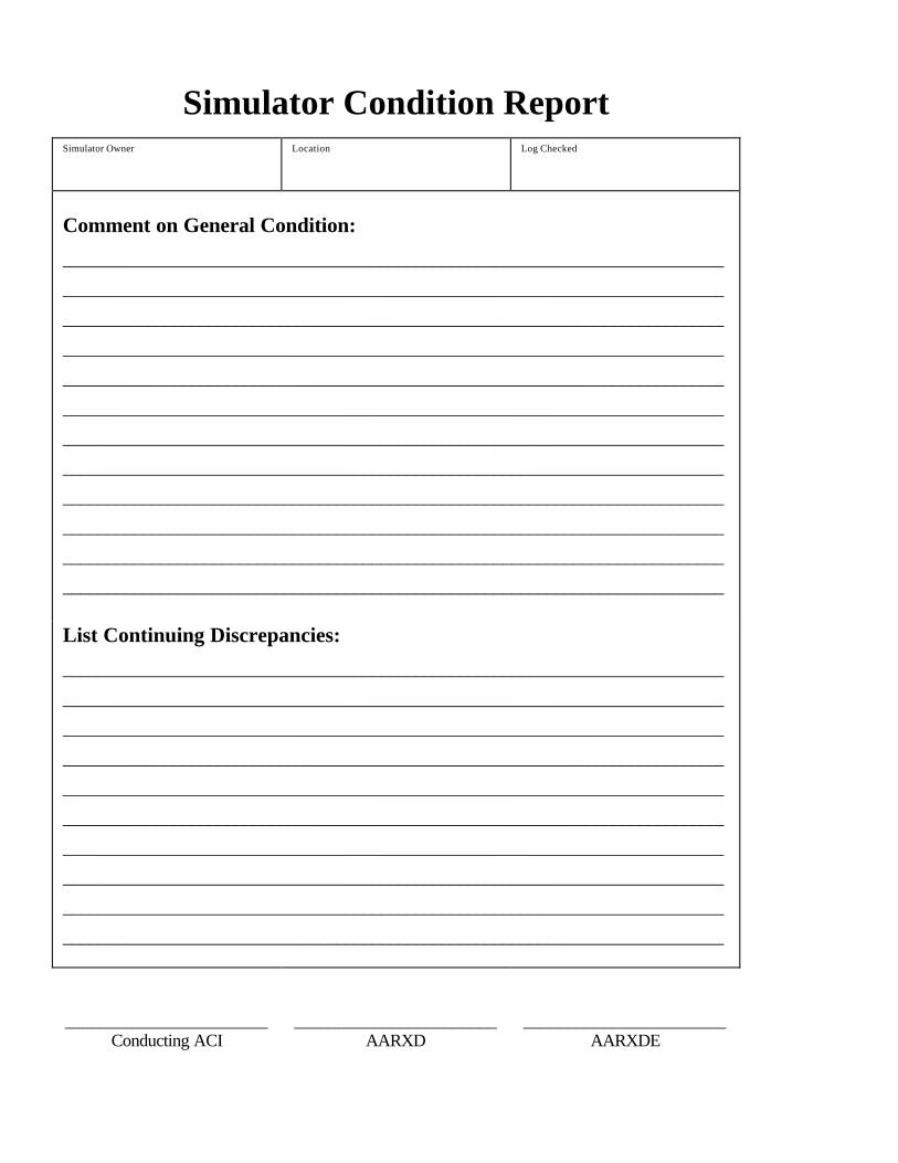
Simulator Condition Report
Simulator Owner Location Log Checked
Comment on General Condition:
___________________________________________________________________________
___________________________________________________________________________
___________________________________________________________________________
___________________________________________________________________________
___________________________________________________________________________
___________________________________________________________________________
___________________________________________________________________________
___________________________________________________________________________
___________________________________________________________________________
___________________________________________________________________________
___________________________________________________________________________
___________________________________________________________________________
List Continuing Discrepancies:
___________________________________________________________________________
___________________________________________________________________________
___________________________________________________________________________
___________________________________________________________________________
___________________________________________________________________________
___________________________________________________________________________
___________________________________________________________________________
___________________________________________________________________________
___________________________________________________________________________
___________________________________________________________________________
_______________________ Conducting ACI
_______________________ AARXD
_______________________ AARXDE
Aeroplane And Rotorcraft Simulator Manual Revision 2 - January 1998
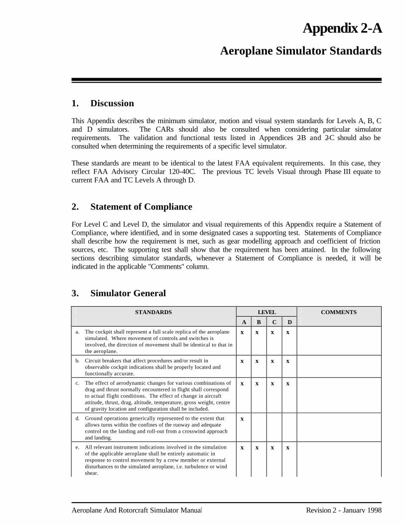
Appendix 2-A Aeroplane Simulator Standards 1. Discussion This Appendix describes the minimum simulator, motion and visual system standards for Levels A, B, C and D simulators. The CARs should also be consulted when considering particular simulator requirements. The validation and functional tests listed in Appendices 2-B and 2-C should also be consulted when determining the requirements of a specific level simulator. These standards are meant to be identical to the latest FAA equivalent requirements. In this case, they reflect FAA Advisory Circular 120-40C. The previous TC levels Visual through Phase III equate to current FAA and TC Levels A through D. 2. Statement of Compliance For Level C and Level D, the simulator and visual requirements of this Appendix require a Statement of Compliance, where identified, and in some designated cases a supporting test. Statements of Compliance shall describe how the requirement is met, such as gear modelling approach and coefficient of friction sources, etc. The supporting test shall show that the requirement has been attained. In the following sections describing simulator standards, whenever a Statement of Compliance is needed, it will be indicated in the applicable "Comments" column. 3. Simulator General
STANDARDS LEVEL COMMENTS
A B C D
a. The cockpit shall represent a full scale replica of the aeroplane simulated. Where movement of controls and switches is involved, the direction of movement shall be identical to that in the aeroplane.
x x x x
b. Circuit breakers that affect procedures and/or result in observable cockpit indications shall be properly located and functionally accurate.
x x x x
c. The effect of aerodynamic changes for various combinations of drag and thrust normally encountered in flight shall correspond to actual flight conditions. The effect of change in aircraft attitude, thrust, drag, altitude, temperature, gross weight, centre of gravity location and configuration shall be included.
x x x x
d. Ground operations generically represented to the extent that allows turns within the confines of the runway and adequate control on the landing and roll-out from a crosswind approach and landing.
x
e. All relevant instrument indications involved in the simulation of the applicable aeroplane shall be entirely automatic in response to control movement by a crew member or external disturbances to the simulated aeroplane, i.e. turbulence or wind shear.
x x x x
Page 2-A-2 Appendix 2-A: Aeroplane Simulator Standards
Revision 2 - January 1998 Aeroplane And Rotorcraft Simulator Manual
STANDARDS LEVEL COMMENTS
A B C D
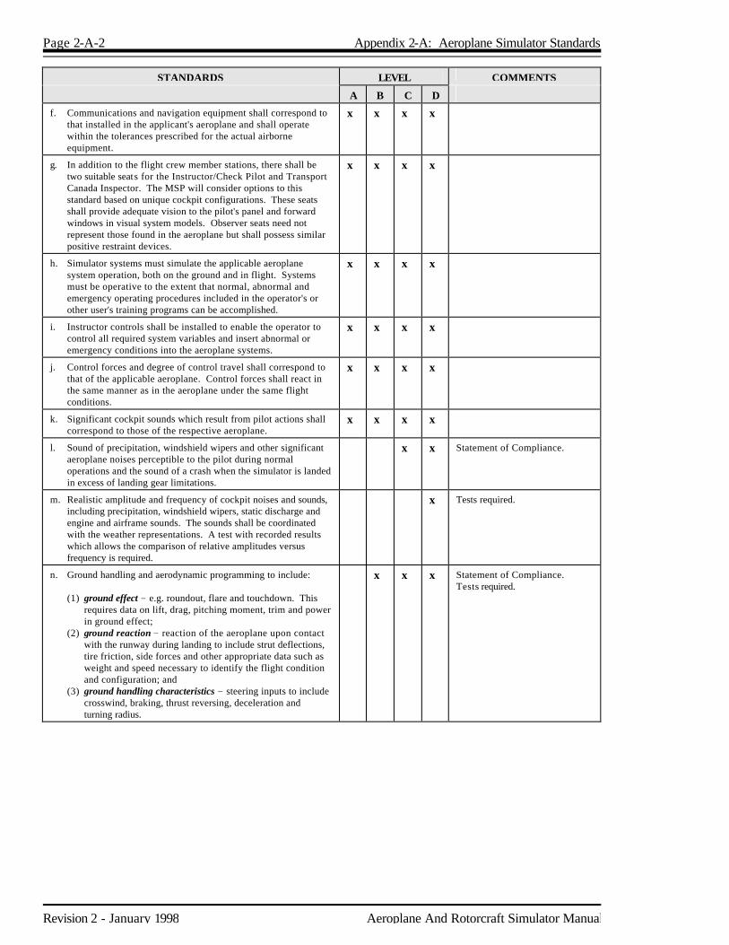
f. Communications and navigation equipment shall correspond to that installed in the applicant's aeroplane and shall operate within the tolerances prescribed for the actual airborne equipment.
x x x x
g. In addition to the flight crew member stations, there shall be two suitable seats for the Instructor/Check Pilot and Transport Canada Inspector. The MSP will consider options to this standard based on unique cockpit configurations. These seats shall provide adequate vision to the pilot's panel and forward windows in visual system models. Observer seats need not represent those found in the aeroplane but shall possess similar positive restraint devices.
x x x x
h. Simulator systems must simulate the applicable aeroplane system operation, both on the ground and in flight. Systems must be operative to the extent that normal, abnormal and emergency operating procedures included in the operator's or other user's training programs can be accomplished.
x x x x
i. Instructor controls shall be installed to enable the operator to control all required system variables and insert abnormal or emergency conditions into the aeroplane systems.
x x x x
j. Control forces and degree of control travel shall correspond to that of the applicable aeroplane. Control forces shall react in the same manner as in the aeroplane under the same flight conditions.
x x x x
k. Significant cockpit sounds which result from pilot actions shall correspond to those of the respective aeroplane.
x x x x
l. Sound of precipitation, windshield wipers and other significant aeroplane noises perceptible to the pilot during normal operations and the sound of a crash when the simulator is landed in excess of landing gear limitations.
x x Statement of Compliance.
m. Realistic amplitude and frequency of cockpit noises and sounds, including precipitation, windshield wipers, static discharge and engine and airframe sounds. The sounds shall be coordinated with the weather representations. A test with recorded results which allows the comparison of relative amplitudes versus frequency is required.
x Tests required.
n. Ground handling and aerodynamic programming to include: (1) ground effect - e.g. roundout, flare and touchdown. This
requires data on lift, drag, pitching moment, trim and power in ground effect;
(2) ground reaction - reaction of the aeroplane upon contact with the runway during landing to include strut deflections, tire friction, side forces and other appropriate data such as weight and speed necessary to identify the flight condition and configuration; and
(3) ground handling characteristics - steering inputs to include crosswind, braking, thrust reversing, deceleration and turning radius.
x x x Statement of Compliance. Tests required.
Appendix 2-A: Aeroplane Simulator Standards Page 2-A-3
Aeroplane And Rotorcraft Simulator Manual Revision 2 - January 1998
STANDARDS LEVEL COMMENTS
A B C D
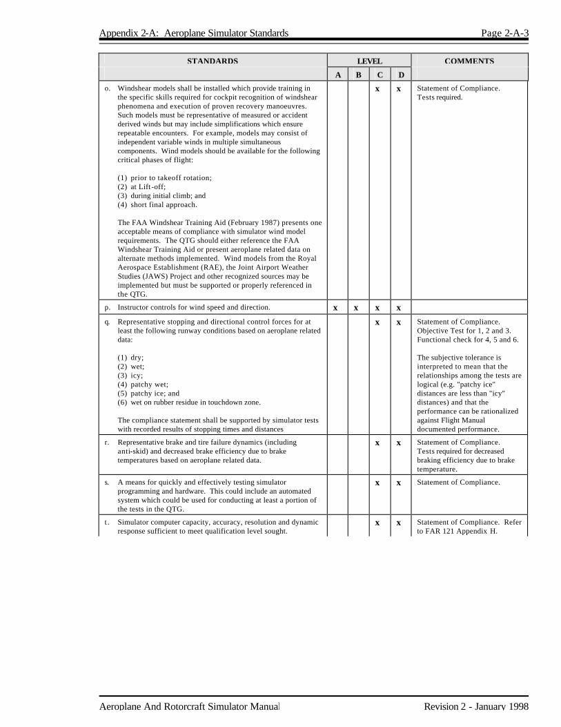
o. Windshear models shall be installed which provide training in the specific skills required for cockpit recognition of windshear phenomena and execution of proven recovery manoeuvres. Such models must be representative of measured or accident derived winds but may include simplifications which ensure repeatable encounters. For example, models may consist of independent variable winds in multiple simultaneous components. Wind models should be available for the following critical phases of flight:
(1) prior to takeoff rotation; (2) at Lift -off; (3) during initial climb; and (4) short final approach. The FAA Windshear Training Aid (February 1987) presents one
acceptable means of compliance with simulator wind model requirements. The QTG should either reference the FAA Windshear Training Aid or present aeroplane related data on alternate methods implemented. Wind models from the Royal Aerospace Establishment (RAE), the Joint Airport Weather Studies (JAWS) Project and other recognized sources may be implemented but must be supported or properly referenced in the QTG.
x x Statement of Compliance. Tests required.
p. Instructor controls for wind speed and direction. x x x x
q. Representative stopping and directional control forces for at least the following runway conditions based on aeroplane related data:
(1) dry; (2) wet; (3) icy; (4) patchy wet; (5) patchy ice; and (6) wet on rubber residue in touchdown zone. The compliance statement shall be supported by simulator tests
with recorded results of stopping times and distances
x x Statement of Compliance. Objective Test for 1, 2 and 3. Functional check for 4, 5 and 6. The subjective tolerance is interpreted to mean that the relationships among the tests are logical (e.g. "patchy ice" distances are less than "icy" distances) and that the performance can be rationalized against Flight Manual documented performance.
r. Representative brake and tire failure dynamics (including anti-skid) and decreased brake efficiency due to brake temperatures based on aeroplane related data.
x x Statement of Compliance. Tests required for decreased braking efficiency due to brake temperature.
s. A means for quickly and effectively testing simulator programming and hardware. This could include an automated system which could be used for conducting at least a portion of the tests in the QTG.
x x Statement of Compliance.
t . Simulator computer capacity, accuracy, resolution and dynamic response sufficient to meet qualification level sought.
x x Statement of Compliance. Refer to FAR 121 Appendix H.
Page 2-A-4 Appendix 2-A: Aeroplane Simulator Standards
Revision 2 - January 1998 Aeroplane And Rotorcraft Simulator Manual
STANDARDS LEVEL COMMENTS
A B C D
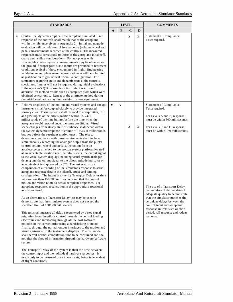
u. Control feel dynamics replicate the aeroplane simulated. Free response of the controls shall match that of the aeroplane within the tolerance given in Appendix 2. Initial and upgrade evaluation will include control free response (column, wheel and pedal) measurements recorded at the controls. The measured responses must correspond to those of the aeroplane in takeoff, cruise and landing configurations. For aeroplanes with irreversible control systems, measurements may be obtained on the ground if proper pilot static inputs are provided to represent conditions typical of those encountered in flight. Engineering validation or aeroplane manufacturer rationale will be submitted as justification to ground test or omit a configuration. For simulators requiring static and dynamic tests at the controls, special test fixtures will not be required during initial evaluations if the operator's QTG shows both test fixture results and alternate test method results such as computer plots which were obtained concurrently. Repeat of the alternate method during the initial evaluation may then satisfy this test equipment.
x x Statement of Compliance. Tests required.
v. Relative responses of the motion and visual systems and cockpit instruments shall be coupled closely to provide integrated sensory cues. These systems shall respond to abrupt pitch, roll and yaw inputs at the pilot's position within 150/300 milliseconds of the time but not before the time when the aeroplane would respond under the same conditions. Visual scene changes from steady state disturbance shall occur within the system dynamic response tolerance of 150/300 milliseconds but not before the resultant motion onset. The test to determine compliance with those requirements shall include simultaneously recording the analogue output from the pilot's control column, wheel and pedals, the output from an accelerometer attached to the motion system platform located at an acceptable location near the pilot's seats, the output signal to the visual system display (including visual system analogue delays) and the output signal to the pilot's attitude indicator or an equivalent test approved by TC. The test results in a comparison of a recording of the simulator's response to actual aeroplane response data in the takeoff, cruise and landing configuration. The intent is to verify Transport Delays or time lags are less than 150/300 milliseconds and that the cues of motion and vision relate to actual aeroplane responses. For aeroplane response, acceleration in the appropriate rotational axis is preferred.
As an alternative, a Transport Delay test may be used to
demonstrate that the simulator system does not exceed the specified limit of 150/300 milliseconds.
This test shall measure all delay encountered by a step signal
migrating from the pilot's control through the control loading electronics and interfacing through all the host software modules in the correct order using a handshaking protocol; finally, through the normal output interfaces to the motion and visual systems or to the instrument displays. The test mode shall permit normal computation time to be consumed and shall not alter the flow of information through the hardware/software system.
The Transport Delay of the system is then the time between
the control input and the individual hardware responses. It needs only to be measured once in each axis, being independent of flight conditions.
x x x
x
Statement of Compliance. Tests required. For Levels A and B, response must be within 300 milliseconds. For Levels C and D, response must be within 150 milliseconds. The use of a Transport Delay test requires flight test data of adequate quality to demonstrate that the simulator matches the aeroplane delays between the control input and aeroplane response in tests such as short period, roll response and rudder response.
Appendix 2-A: Aeroplane Simulator Standards Page 2-A-5
Aeroplane And Rotorcraft Simulator Manual Revision 2 - January 1998
STANDARDS LEVEL COMMENTS
A B C D
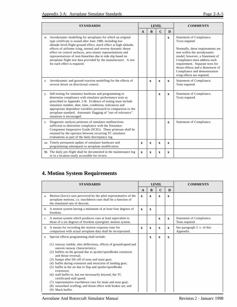
w. Aerodynamic modelling for aeroplanes for which an original type certificate is issued after June 1980, including low altitude-level-flight ground effect, mach effect at high altitude, effects of airframe icing, normal and reverse dynamic thrust effect on control surfaces, aero-elastic representations and representations of non-linearities due to side slip based on aeroplane flight test data provided by the manufacturer. A test for each effect is required.
x Statement of Compliance. Tests required. Normally, these requirements are met within the aerodynamic model; however, a Statement of Compliance must address each requirement. Separate tests for thrust effects and a Statement of Compliance and demonstration icing effects are required.
x. Aerodynamic and ground reaction modelling for the effects of reverse thrust on directional control.
x x x Statement of Compliance. Tests required.
y. Self-testing for simulator hardware and programming to determine compliance with simulator performance tests as prescribed in Appendix 2-B. Evidence of testing must include simulator number, date, time, conditions, tolerances and appropriate dependent variables portrayed in comparison to the aeroplane standard. Automatic flagging of "out-of-tolerance" situations is encouraged.
x x Statement of Compliance. Tests required.
z. Diagnostic analysis printouts of simulator malfunctions sufficient to determine compliance with the Simulator Component Inoperative Guide (SCIG). These printouts shall be retained by the operator between recurring TC simulator evaluations as part of the daily discrepancy log.
x Statement of Compliance.
aa. Timely permanent update of simulator hardware and programming subsequent to aeroplane modification.
x x x x
bb. The daily pre-flight shall be documented in the maintenance log or in a location easily accessible for review.
x x x x
4. Motion System Requirements
STANDARDS LEVEL COMMENTS
A B C D
a. Motion (force) cues perceived by the pilot representative of the aeroplane motions, i.e. touchdown cues shall be a function of the simulated rate of descent.
x x x x
b. A motion system having a minimum of at least four degrees of freedom.
x x
c. A motion system which produces cues at least equivalent to those of a six degrees of freedom synergistic motion system.
x x Statement of Compliance. Tests required.
d. A means for recording the motion response time for comparison with actual aeroplane data shall be incorporated.
x x x x See paragraph 3. v. of this Appendix.
e. Special effects programming shall include: (1) runway rumble, oleo deflections, effects of ground-speed and
uneven runway characteristics; (2) buffets on the ground due to spoiler/speedbrake extension
and thrust reversal; (3) bumps after lift -off of nose and main gear; (4) buffet during extension and retraction of landing gear; (5) buffet in the air due to flap and spoiler/speedbrake
extension; (6) stall buffet to, but not necessarily beyond, the TC
certificated stall speed; (7) representative touchdown cues for main and nose gear; (8) nosewheel scuffing; and thrust effect with brakes set; and (9) Mach buffet.
x x x

Page 2-A-6 Appendix 2-A: Aeroplane Simulator Standards
Revision 2 - January 1998 Aeroplane And Rotorcraft Simulator Manual
STANDARDS LEVEL COMMENTS
A B C D
f. Characteristic buffet motions that result from operation of the aeroplane (e.g. high speed buffet, extended landing gear, flaps, nose-wheel scuffing, stall) which can be sensed at the flight deck. The simulator shall be programmed and instrumented in such a manner that the characteristic buffet modes can be measured and compared to aeroplane data. Aeroplane data are also required to define flight deck motions when the aeroplane is subjected to atmospheric disturbances. General purpose disturbance models that approximate demonstrable flight test data are acceptable. A test with recorded results which allows the comparison of relative amplitudes versus frequency is required.
x Statement of Compliance. Tests required.
5. Visual System Requirements
STANDARDS LEVEL COMMENTS
A B C D
a. The visual system shall be capable of meeting all standards of this Appendix and Appendices 2-B and 2-C (Validation and Functional Test Appendices) as applicable to the level of qualification requested by the applicant.
x x x x
b. The optical system shall be capable of providing at least a 45° horizontal and 30° vertical field of view simultaneously for each pilot.
x x
c. Continuous minimum visual field of view of 75° horizontal and 30° vertical per pilot seat. Both pilot seat visual systems shall be able to be operated simultaneously.
x x Wide angle systems providing cross cockpit viewing must provide a minimum of 150 degrees horizontal field of view; 75 degrees per pilot operated simultaneously
d. A measure of recording the visual response time. x x x x
Appendix 2-A: Aeroplane Simulator Standards Page 2-A-7
Aeroplane And Rotorcraft Simulator Manual Revision 2 - January 1998
STANDARDS LEVEL COMMENTS
A B C D
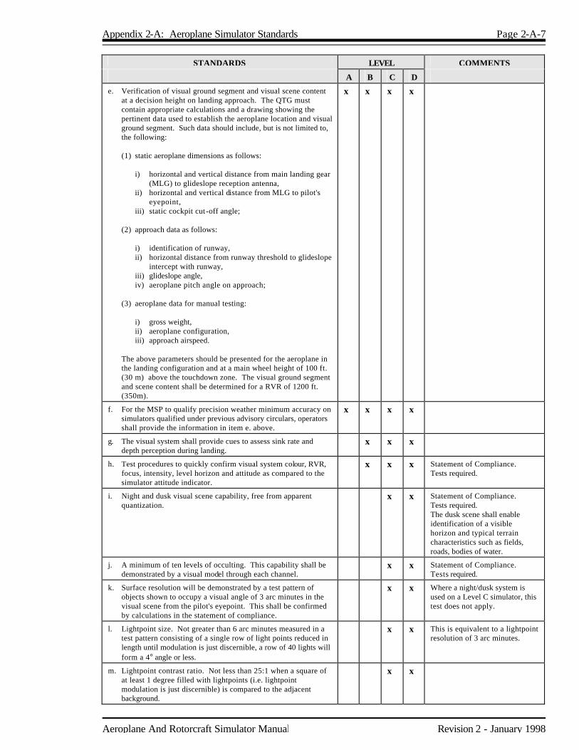
e. Verification of visual ground segment and visual scene content at a decision height on landing approach. The QTG must contain appropriate calculations and a drawing showing the pertinent data used to establish the aeroplane location and visual ground segment. Such data should include, but is not limited to, the following:
(1) static aeroplane dimensions as follows: i) horizontal and vertical distance from main landing gear
(MLG) to glideslope reception antenna, ii) horizontal and vertical distance from MLG to pilot's
eyepoint, iii) static cockpit cut -off angle; (2) approach data as follows: i) identification of runway, ii) horizontal distance from runway threshold to glideslope
intercept with runway, iii) glideslope angle, iv) aeroplane pitch angle on approach; (3) aeroplane data for manual testing: i) gross weight, ii) aeroplane configuration, iii) approach airspeed. The above parameters should be presented for the aeroplane in
the landing configuration and at a main wheel height of 100 ft. (30 m) above the touchdown zone. The visual ground segment and scene content shall be determined for a RVR of 1200 ft. (350m).
x x x x
f. For the MSP to qualify precision weather minimum accuracy on simulators qualified under previous advisory circulars, operators shall provide the information in item e. above.
x x x x
g. The visual system shall provide cues to assess sink rate and depth perception during landing.
x x x
h. Test procedures to quickly confirm visual system colour, RVR, focus, intensity, level horizon and attitude as compared to the simulator attitude indicator.
x x x Statement of Compliance. Tests required.
i. Night and dusk visual scene capability, free from apparent quantization.
x x Statement of Compliance. Tests required. The dusk scene shall enable identification of a visible horizon and typical terrain characteristics such as fields, roads, bodies of water.
j. A minimum of ten levels of occulting. This capability shall be demonstrated by a visual model through each channel.
x x Statement of Compliance. Tests required.
k. Surface resolution will be demonstrated by a test pattern of objects shown to occupy a visual angle of 3 arc minutes in the visual scene from the pilot's eyepoint. This shall be confirmed by calculations in the statement of compliance.
x x Where a night/dusk system is used on a Level C simulator, this test does not apply.
l. Lightpoint size. Not greater than 6 arc minutes measured in a test pattern consisting of a single row of light points reduced in length until modulation is just discernible, a row of 40 lights will form a 4° angle or less.
x x This is equivalent to a lightpoint resolution of 3 arc minutes.
m. Lightpoint contrast ratio. Not less than 25:1 when a square of at least 1 degree filled with lightpoints (i.e. lightpoint modulation is just discernible) is compared to the adjacent background.
x x
Page 2-A-8 Appendix 2-A: Aeroplane Simulator Standards
Revision 2 - January 1998 Aeroplane And Rotorcraft Simulator Manual
STANDARDS LEVEL COMMENTS
A B C D
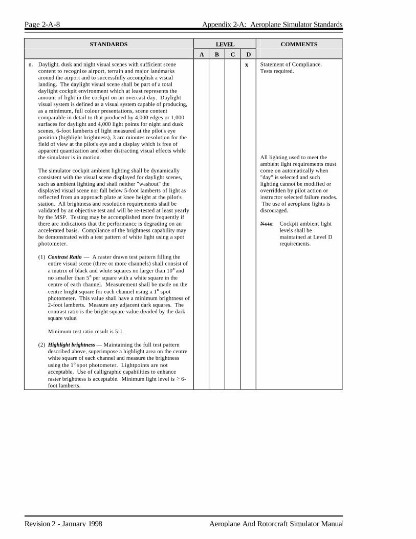
n. Daylight, dusk and night visual scenes with sufficient scene content to recognize airport, terrain and major landmarks around the airport and to successfully accomplish a visual landing. The daylight visual scene shall be part of a total daylight cockpit environment which at least represents the amount of light in the cockpit on an overcast day. Daylight visual system is defined as a visual system capable of producing, as a minimum, full colour presentations, scene content comparable in detail to that produced by 4,000 edges or 1,000 surfaces for daylight and 4,000 light points for night and dusk scenes, 6-foot lamberts of light measured at the pilot's eye position (highlight brightness), 3 arc minutes resolution for the field of view at the pilot's eye and a display which is free of apparent quantization and other distracting visual effects while the simulator is in motion.
The simulator cockpit ambient lighting shall be dynamically
consistent with the visual scene displayed for daylight scenes, such as ambient lighting and shall neither "washout" the displayed visual scene nor fall below 5-foot lamberts of light as reflected from an approach plate at knee height at the pilot's station. All brightness and resolution requirements shall be validated by an objective test and will be re-tested at least yearly by the MSP. Testing may be accomplished more frequently if there are indications that the performance is degrading on an accelerated basis. Compliance of the brightness capability may be demonstrated with a test pattern of white light using a spot photometer.
(1) Contrast Ratio — A raster drawn test pattern filling the
entire visual scene (three or more channels) shall consist of a matrix of black and white squares no larger than 10° and no smaller than 5° per square with a white square in the centre of each channel. Measurement shall be made on the centre bright square for each channel using a 1° spot photometer. This value shall have a minimum brightness of 2-foot lamberts. Measure any adjacent dark squares. The contrast ratio is the bright square value divided by the dark square value.
Minimum test ratio result is 5:1. (2) Highlight brightness — Maintaining the full test pattern
described above, superimpose a highlight area on the centre white square of each channel and measure the brightness using the 1° spot photometer. Lightpoints are not acceptable. Use of calligraphic capabilities to enhance raster brightness is acceptable. Minimum light level is ≥ 6-foot lamberts.
x Statement of Compliance. Tests required. All lighting used to meet the ambient light requirements must come on automatically when "day" is selected and such lighting cannot be modified or overridden by pilot action or instructor selected failure modes. The use of aeroplane lights is discouraged. Note: Cockpit ambient light
levels shall be maintained at Level D requirements.
Aeroplane And Rotorcraft Simulator Manual Revision 2 - January 1998
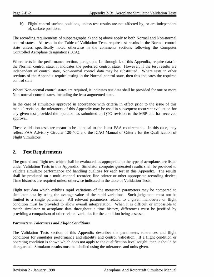
Appendix 2-B Aeroplane Simulator Validation Tests 1. Discussion Simulator performance and system operation shall be objectively evaluated by comparing each performance and stability and control test conducted in the simulator to aeroplane data unless specifically noted otherwise. To facilitate the validation of the simulator, a multi-channel recorder, line printer or other appropriate device, acceptable to the MSP, shall be used to record each validation test. The results of these recordings shall then be compared to the aeroplane source data. Certain visual, sound and motion tests in this appendix are not necessarily based upon validation data with specific tolerances. However, these tests are included here for completeness, and the required criteria must be fulfilled instead of meeting a specific tolerance. The QTG provided by the operator shall describe clearly and distinctly how the simulator will be set up and operated for each test. Use of a drive program designed to automatically accomplish the tests is encouraged but procedures shall be included to positively determine that the driver is doing nothing more than accurately flying the simulator. It is not the intent and it is not acceptable to TC to test each simulator subsystem independently. Overall integrated testing of the simulator must be accomplished to assure that the total simulator system meets the prescribed standards. A manual test procedure with explicit and detailed steps for completion of each test must also be provided. The tests and tolerances contained in this Appendix shall be included in the sponsor's QTG. Simulators must be compared to flight test data except as otherwise specified. For aeroplanes certified prior to January 1992, the sponsor may, after reasonable attempts to obtain suitable flight test data have failed, indicate in the QTG where flight test data is unavailable or unsuitable for a specific test. For such a test, alternative data shall be submitted to the MSP for approval. Submissions for approval of data other than flight test shall include an explanation of validity with respect to available flight test information. The tolerances specified in the Validation Tests section of this Appendix generally indicate the test results required. Unless otherwise specified, tests shall represent aeroplane performance at normal operating weights and centres of gravity. If a test is supported by aeroplane data at one extreme gross weight or centre of gravity, another test supported by aeroplane data as close as possible to the other extreme shall be included. Tests of stability and control shall include validation of augmentation devices. For the testing of Computer Controlled Aeroplane (CCA), or other highly augmented aeroplane simulators, flight test data are required for both the Normal (N) and Non-normal (NN) control states, as indicated in the validation requirements of this appendix. Tests in the non-normal state will always include the least augmented state. Tests for other levels of control state degradation may be detailed by the MSP at the time of definition of a set specific aeroplane tests for simulator data. Where applicable, flight test data must record:
a) Pilot controller deflections or electronically generated inputs, including location of input; and
Page 2-B-2 Appendix 2-B: Aeroplane Simulator Validation Tests
Revision 2 - January 1998 Aeroplane And Rotorcraft Simulator Manual
b) Flight control surface positions, unless test results are not affected by, or are independent of, surface positions.
The recording requirements of subparagraphs a) and b) above apply to both Normal and Non-normal control states. All tests in the Table of Validation Tests require test results in the Normal control state unless specifically noted otherwise in the comments sections following the Computer Controlled Aeroplane designation (CCA). Where tests in the performance section, paragraphs 1a. through f. of this Appendix, require data in the Normal control state, it indicates the preferred control state. However, if the test results are independent of control state, Non-normal control data may be substituted. Where tests in other sections of the Appendix require testing in the Normal control state, then this indicates the required control state. Where Non-normal control states are required, it indicates test data shall be provided for one or more Non-normal control states, including the least augmented state. In the case of simulators approved in accordance with criteria in effect prior to the issue of this manual revision, the tolerances of this Appendix may be used in subsequent recurrent evaluation for any given test provided the operator has submitted an QTG revision to the MSP and has received approval. These validation tests are meant to be identical to the latest FAA requirements. In this case, they reflect FAA Advisory Circular 120-40C and the ICAO Manual of Criteria for the Qualification of Flight Simulators. 2. Test Requirements The ground and flight test which shall be evaluated, as appropriate to the type of aeroplane, are listed under Validation Tests in this Appendix. Simulator computer generated results shall be provided to validate simulator performance and handling qualities for each test in this Appendix. The results shall be produced on a multi-channel recorder, line printer or other appropriate recording device. Time histories are required unless otherwise indicated in the table of Validation Tests. Flight test data which exhibits rapid variations of the measured parameters may be compared to simulator data by using the average value of the rapid variations. Such judgement must not be limited to a single parameter. All relevant parameters related to a given manoeuvre or flight condition must be provided to allow overall interpretation. When it is difficult or impossible to match simulator to aeroplane data throughout a time history, differences must be justified by providing a comparison of other related variables for the condition being assessed. Parameters, Tolerances and Flight Conditions The Validation Tests section of this Appendix describes the parameters, tolerances and flight conditions for simulator performance and stability and control validation. If a flight condition or operating condition is shown which does not apply to the qualification level sought, then it should be disregarded. Simulator results must be labelled using the tolerances and units given.

Appendix 2-B: Aeroplane Simulator Validation Tests Page 2-B-3
Aeroplane And Rotorcraft Simulator Manual Revision 2 - January 1998
Flight Conditions Verification When comparing the parameters listed to those of the aeroplane, sufficient data must also be provided to verify the correct flight conditions. For example, to show that control force is within ±5 lb (2.225 daN) in a static stability test, data to show the correct airspeed, power, thrust or torque, aeroplane configuration, altitude and other appropriate datum identification parameters shall also be given. If comparing short period dynamics, normal acceleration may be used to establish a match to the aeroplane, but airspeed, altitude, control input, aeroplane configuration and other appropriate data shall also be given. All airspeed values shall be clearly annotated as to indicated, calibrated, etc., and like values used for comparison. 3. Table of Validation Tests
I = Initial Evaluation R = Recurrent Evaluation
Test Tolerance Flt Condition Requirement Comments
A B C D 1. PERFORMANCE
A. Taxi
1. Minimum Radius Turn ±3 ft (0.9 m) or 20% of Aeroplane Turn Radius
Ground/Takeoff IR IR IR Plot for both Main and Nosegear turning radius. Data for no brakes and minimum thrust except for aeroplanes requiring asymmetric thrust or braking to turn.
2. Rate of Turn Versus Nosewheel Steering Angle
±10% or ±2°/sec Turn Rate
Ground/Takeoff IR IR IR Plot for a minimum of two speeds, greater than minimum turning radius speed, with a spread of at least 5 Knots.
B. Takeoff
1. Ground Acceleration Time and Distance
±5% Time and Distance or ±5% Time and ±200 ft (61 m) of Distance
Ground/Takeoff IR IR IR IR Unfactored aircraft certification data may be used. Acceleration Time and Distance should be recorded as a minimum of 80% of total segment. (Brake release to Vr.)
2. Minimum Control Speed, Ground (Vmcg) Aerodynamic Controls Only per Applicable Airworthiness Standard or Low Speed, Engine Inoperative Ground Control Characteristics
or Low Speed, Engine
Inoperative Ground Control Characteristics
25% of Maximum Aeroplane Deviation from Runway Centreline or ±5 ft (1.5 m).
Ground/Takeoff IR IR IR IR Engine failure speed must be within ±1 Knot of aeroplane engine failure speed. Engine thrust decay must be that resulting from the mathematical model for the engine variant applicable to the simulator under test. If the modelled engine variant is not the same as the aeroplane manufacturers' flight test engine, then a further test may be run with the same initial conditions using the thrust from the flight test data as the driving parameter. Aeroplanes with reversible flight control systems must also plot Rudder Pedal Force (±10% or ±2.2 daN (5 lbs)).
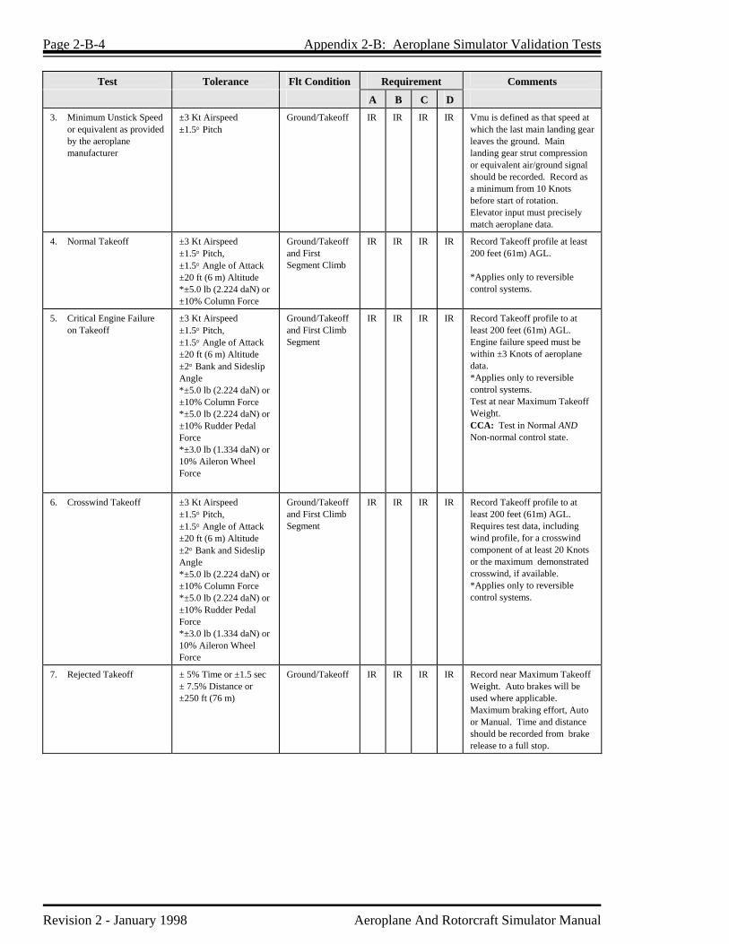
Page 2-B-4 Appendix 2-B: Aeroplane Simulator Validation Tests
Revision 2 - January 1998 Aeroplane And Rotorcraft Simulator Manual
Test Tolerance Flt Condition Requirement Comments
A B C D 3. Minimum Unstick Speed
or equivalent as provided by the aeroplane manufacturer
±3 Kt Airspeed ±1.5° Pitch
Ground/Takeoff IR IR IR IR Vmu is defined as that speed at which the last main landing gear leaves the ground. Main landing gear strut compression or equivalent air/ground signal should be recorded. Record as a minimum from 10 Knots before start of rotation. Elevator input must precisely match aeroplane data.
4. Normal Takeoff ±3 Kt Airspeed ±1.5° Pitch, ±1.5° Angle of Attack ±20 ft (6 m) Altitude *±5.0 lb (2.224 daN) or ±10% Column Force
Ground/Takeoff and First Segment Climb
IR IR IR IR Record Takeoff profile at least 200 feet (61m) AGL. *Applies only to reversible control systems.
5. Critical Engine Failure on Takeoff
±3 Kt Airspeed ±1.5° Pitch, ±1.5° Angle of Attack ±20 ft (6 m) Altitude ±2° Bank and Sideslip Angle *±5.0 lb (2.224 daN) or ±10% Column Force *±5.0 lb (2.224 daN) or ±10% Rudder Pedal Force *±3.0 lb (1.334 daN) or 10% Aileron Wheel Force
Ground/Takeoff and First Climb Segment
IR IR IR IR Record Takeoff profile to at least 200 feet (61m) AGL. Engine failure speed must be within ±3 Knots of aeroplane data. *Applies only to reversible control systems. Test at near Maximum Takeoff Weight. CCA: Test in Normal AND Non-normal control state.
6. Crosswind Takeoff ±3 Kt Airspeed ±1.5° Pitch, ±1.5° Angle of Attack ±20 ft (6 m) Altitude ±2° Bank and Sideslip Angle *±5.0 lb (2.224 daN) or ±10% Column Force *±5.0 lb (2.224 daN) or ±10% Rudder Pedal Force *±3.0 lb (1.334 daN) or 10% Aileron Wheel Force
Ground/Takeoff and First Climb Segment
IR IR IR IR Record Takeoff profile to at least 200 feet (61m) AGL. Requires test data, including wind profile, for a crosswind component of at least 20 Knots or the maximum demonstrated crosswind, if available. *Applies only to reversible control systems.
7. Rejected Takeoff
± 5% Time or ±1.5 sec ± 7.5% Distance or ±250 ft (76 m)
Ground/Takeoff
IR IR IR IR Record near Maximum Takeoff Weight. Auto brakes will be used where applicable. Maximum braking effort, Auto or Manual. Time and distance should be recorded from brake release to a full stop.
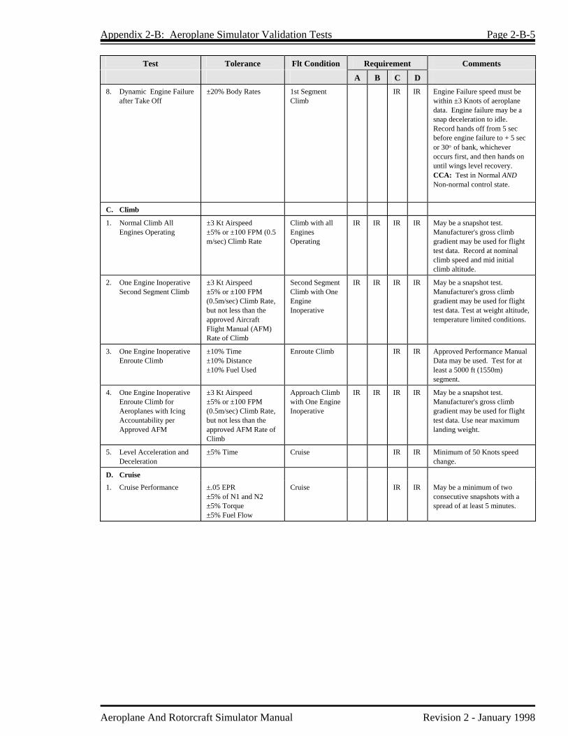
Appendix 2-B: Aeroplane Simulator Validation Tests Page 2-B-5
Aeroplane And Rotorcraft Simulator Manual Revision 2 - January 1998
Test Tolerance Flt Condition Requirement Comments
A B C D 8. Dynamic Engine Failure
after Take Off ±20% Body Rates 1st Segment
Climb IR IR Engine Failure speed must be
within ±3 Knots of aeroplane data. Engine failure may be a snap deceleration to idle. Record hands off from 5 sec before engine failure to + 5 sec or 30° of bank, whichever occurs first, and then hands on until wings level recovery. CCA: Test in Normal AND Non-normal control state.
C. Climb
1. Normal Climb All Engines Operating
±3 Kt Airspeed ±5% or ±100 FPM (0.5 m/sec) Climb Rate
Climb with all Engines Operating
IR IR IR IR May be a snapshot test. Manufacturer's gross climb gradient may be used for flight test data. Record at nominal climb speed and mid initial climb altitude.
2. One Engine Inoperative Second Segment Climb
±3 Kt Airspeed ±5% or ±100 FPM (0.5m/sec) Climb Rate, but not less than the approved Aircraft Flight Manual (AFM) Rate of Climb
Second Segment Climb with One Engine Inoperative
IR IR IR IR May be a snapshot test. Manufacturer's gross climb gradient may be used for flight test data. Test at weight altitude, temperature limited conditions.
3. One Engine Inoperative Enroute Climb
±10% Time ±10% Distance ±10% Fuel Used
Enroute Climb IR IR Approved Performance Manual Data may be used. Test for at least a 5000 ft (1550m) segment.
4. One Engine Inoperative Enroute Climb for Aeroplanes with Icing Accountability per Approved AFM
±3 Kt Airspeed ±5% or ±100 FPM (0.5m/sec) Climb Rate, but not less than the approved AFM Rate of Climb
Approach Climb with One Engine Inoperative
IR IR IR IR May be a snapshot test. Manufacturer's gross climb gradient may be used for flight test data. Use near maximum landing weight.
5. Level Acceleration and Deceleration
+5% Time Cruise IR IR Minimum of 50 Knots speed change.
D. Cruise
1. Cruise Performance +.05 EPR +5% of N1 and N2 +5% Torque +5% Fuel Flow
Cruise IR IR May be a minimum of two consecutive snapshots with a spread of at least 5 minutes.

Page 2-B-6 Appendix 2-B: Aeroplane Simulator Validation Tests
Revision 2 - January 1998 Aeroplane And Rotorcraft Simulator Manual
Test Tolerance Flt Condition Requirement Comments
A B C D E. Stopping
1. Stopping Time and Distance, Wheel Brakes Dry Runway
(No Reverse Thrust)
±5% of Time. For distance up to 4000 ft (1220 m) ±200 ft (61 m) or ±10%, whichever is smaller. For distance greater than 4000 ft (1220 m) ±5% of Distance
Landing IR IR IR IR Time and Distance should be recorded for at least 80% of the total segment (Touchdown to Full Stop). Data required for Medium, Light, and near Maximum Landing gross weight conditions. Engineering data may be used for the Medium and Light gross weight conditions. Brake system pressure should be available.
2. Stopping Time and Distance, Reverse Thrust Dry Runway
(No Wheel Braking)
±5% Time and the Smaller of ±10% or 200 ft (61 m) of Distance
Landing IR IR IR IR Time and Distance should be recorded for at least 80% of the total time from the initiation of reverse thrust to forward idle. Data required for Medium, Light, and near Maximum Landing gross weights. Engineering data may be used for the Medium and Light gross weight conditions.
3. Stopping Time and Distance, Wheel Brakes Wet Runway (No Reverse Thrust)
±10% or ±200 ft (61 m) Distance
Landing I I Approved AFM data is acceptable.
4. Stopping Time and Distance, Wheel Brakes Icy Runway (No Reverse Thrust)
±10% or ±200 ft (61 m) Distance
Landing I I Approved AFM data is acceptable.
F. Engines
1. Acceleration Ti ±10% Tt ±10%
Approach or Landing
IR IR IR IR Ti = Total time from initial throttle movement until a 10% response of a critical engine parameter. Tt = Total time from Ti to 90% go-around power. Critical engine parameter should be a measurement of power (N¹, N², EPR, Torque, etc.) Plot from flight idle to go-around power for a rapid (slam) throttle movement.
2. Deceleration Ti ±10% Tt ±10%
Ground/Takeoff IR IR IR IR Ti = Total time from initial throttle movement until a 10% response of a critical engine parameter. Tt = Total time from Ti to 90% decay of maximum takeoff power. Plot from maximum take-off power to 90% decay of maximum takeoff power for a rapid (slam) throttle movement.

Appendix 2-B: Aeroplane Simulator Validation Tests Page 2-B-7
Aeroplane And Rotorcraft Simulator Manual Revision 2 - January 1998
Test Tolerance Flt Condition Requirement Comments
A B C D 2. HANDLING
QUALITIES
A. Static Control Checks**
1. Column Position Versus Force and Surface Position Calibration
±2 lb (0.89 daN) Breakout ±5 lb (2.224 daN) or ±10% Force ±2° Elevator
Ground (Validated with Flight Data)
IR IR IR IR Uninterrupted control sweep. Must be validated with in flight data from tests such as Longitudinal Static Stability, Stalls, etc. Static and Dynamic Flight Control tests should be accomplished at the same Feel or Impact pressures. CCA: Position vs Force not applicable if aeroplane cockpit controller is used.
2. Wheel Position Versus Force and Surface Position Calibration
±2 lb (0.89 daN) Breakout ±3 lb (1.334 daN) or ±10% Force ±1° Aileron ±3° Spoiler
Ground (Validated with Flight Data)
IR IR IR IR Uninterrupted control sweep. Must be validated with in flight data from tests such as Engine Out Trims, Steady State Sideslip, etc. Static and Dynamic Flight Control tests should be accomplished at the same Feel or Impact pressures. CCA: Position vs Force not applicable if aeroplane cockpit controller is used and a maintenance program is used to prevent the deterioration of the component.
3. Rudder Position Versus Force and Surface Position Calibration
±5 lb (2.224 daN) Breakout ±5 lb (2.224 daN) or ±10% Force ±2° Rudder
Ground (Validated with Flight Data)
IR IR IR IR Uninterrupted control sweep. Must be validated with in flight data from tests such as Engine Out Trims, Steady State Sideslip, etc. Static and Dynamic Flight Control tests should be accomplished at the same Feel or Impact pressures.
4. Nosewheel Steering Force
±2 lb (0.9 daN) Breakout ±3 lb (1.3 daN) or ±10% Force ±2 Nosewheel Angle
Ground IR IR IR IR Uninterrupted control sweep to stops.
5. Rudder Pedal Steering Calibration
±2° Nosewheel Angle ±5° Deadband
Ground IR IR IR IR Uninterrupted control sweep to stops.
6. Pitch Trim Calibration Indicator Versus Computed
±0.5° of Computer Trim Angle ±10% Trim Rate
Go-Around and Ground
IR IR IR IR Trim Rate to be checked at Pilot Primary induced trim rate (ground) and Autopilot or Pilot Primary trim rate in flight at Go Around flight conditions.
** Column, wheel and pedal position versus force shall be measured at the control. An alternative method in lieu of the test fixture at the
controls would be to instrument the simulator in an equivalent manner to the flight test aeroplane. The force and position data from this instrumentation can be directly recorded and matched to the aeroplane data. Such a permanent installation could be used without any time for installation of external devices.

Page 2-B-8 Appendix 2-B: Aeroplane Simulator Validation Tests
Revision 2 - January 1998 Aeroplane And Rotorcraft Simulator Manual
Test Tolerance Flt Condition Requirement Comments
A B C D 7. Alignment of Power
Lever Angle or Cross Shaft Angle Versus Selected Engine Parameter (EPR, N1)
±5° of Power Lever Angle or Cross Shaft Angle
Ground IR IR IR IR Simultaneous recording for all engines. 5° tolerance applies against aeroplane data and between engines. May be snapshot test. Note: In the case of propeller powered aeroplanes, if an additional lever, usually referred to as the propeller lever, is present, it must also be checked. Where these levers do not have angular travel, a tolerance of ±0.8 inches (2 cm) applies.
8. Brake Pedal Position Versus Force
±5 lb (2.224 daN) or 10% Force ±10% or 150 psi (1033 kPa) Brake Hydraulic Pressure
Ground IR IR IR IR Simulator computer output results may be used to show compliance. Relate hydraulic system pressure to pedal position in a ground static test.
B. Dynamic Control Check**
1. Pitch Control ±10% of time for first zero crossing, and ±10(n+1)% of period thereafter. ±10% amplitude of first overshoot. ±20% of amplitude of second and subsequent overshoots greater than 5% of initial displacement. ±1 overshoot.
Takeoff, Cruise, Landing
IR IR Data should be normal control displacement in both directions. Approximately 25% to 50% of full throw. n is the sequential period of a full cycle of oscillation. Refer to the Control Dynamics section of this Appendix. CCA: Test not applicable if aeroplane controller is installed in the simulator.
2. Roll Control Same as B.1. above. Takeoff, Cruise, Landing
IR IR Data should be normal control displacement. Approximately 25% to 50% of full throw. CCA: Test not applicable if aeroplane controller is installed in the simulator.
3. Yaw Control Same as B.1. above. Takeoff, Cruise, Landing
IR IR Data should be normal control displacement. Approximately 25% to 50% of full throw. CCA: Test not applicable if aeroplane controller is installed in the simulator.
4. Small Control Inputs ± 20% Body Rates Cruise and Approach
IR IR Small control inputs defined as 5% of total travel.
C. Longitudinal
1. Power Change Dynamics ±3 Kt Airspeed ±100 ft (30 m) Altitude ±20% or ±1.5° Pitch
Approach to Go-Around
IR IR IR IR Time history of uncontrolled free response for time increment from 5 sec before the initiation of the configuration change to +15 sec. CCA: Test in Normal AND Non-normal control state.
** Column, wheel and pedal position versus force shall be measured at the control. An alternative method acceptable to the MSP in lieu of the test fixture at the controls would be to instrument the simulator in an equivalent manner to the flight test aeroplane. The force and position data from this instrumentation can be directly recorded and matched to the aeroplane data. Such a permanent installation could be used without any time for installation of external devices.

Appendix 2-B: Aeroplane Simulator Validation Tests Page 2-B-9
Aeroplane And Rotorcraft Simulator Manual Revision 2 - January 1998
Test Tolerance Flt Condition Requirement Comments
A B C D 2. Flap/Slat Change
Dynamics ±3 Kt Airspeed ±100 ft (30 m) Altitude ±20% or 1.5° Pitch
Retraction, After Takeoff. Extension, Approach to Landing
IR
IR
IR
IR
Time history of uncontrolled free response for time increment from 5 sec before the initiation of the configuration change to +15 seconds. CCA: Test in Normal AND Non-normal control state.
3. Spoiler/Speedbrake Change Dynamics
±3 Kt Airspeed ±100 ft (30 m) Altitude ±20% or 1.5° Pitch
Cruise and Approach
IR IR IR IR Time history of uncontrolled free response for time increment from 5 sec before the initiation of the configuration change to +15 sec. Results required for both extension and retraction. CCA: Test in Normal AND Non-normal control state.
4. Gear Change Dynamics ±3 Kt Airspeed ±100 ft (30 m) Altitude ±20% or 1.5° pitch
Takeoff to 2nd Second Segment Climb and Approach to Landing
IR IR IR IR Time history of uncontrolled free response for a time increment of 5 sec before the initiation of the configuration change to +15 sec. CCA: Test in Normal AND Non-normal control state.
5. Gear and Flap/Slat Operating Times
±1 sec or 10% of Time Takeoff, Approach
IR IR IR IR Normal and alternate flaps, extension and retraction. Normal gear, extension and retraction. Alternate gear, extension only. Intermediate increment times not required. Tabular data from production aeroplanes are acceptable.
6. Longitudinal Trim ±1° Pitch Control (Stab and Elev) ±1° Pitch Angle ±5% Net Thrust or Equivalent
Cruise, Approach and Landing
IR IR IR IR May be snapshot tests. CCA: Test in Normal AND Non-normal control state.
7. Longitudinal Manoeuvring Stability (Stick Force per g)
±5 lb (±2.224 daN) or ±10% Column Force or Equivalent Surface
Cruise, Approach and Landing
IR IR IR IR May be series of snapshot tests. Force or surface deflection must be in correct direction. Approximately 20°, 30° and 45° of bank shall be presented. CCA: Test in Normal AND Non-normal control state.
8. Longitudinal Static Stability
±5 lb (±2.224 daN) or ±10% Column Force or Equivalent Surface
Approach IR IR IR IR Data for at least two speeds above and below trim speed. May be snapshot tests. CCA: Test in Normal OR Non-normal control state.
9. Stick Shaker, Airframe Buffet, Stall Speeds
±3 Kt Airspeed ±2° Bank for speeds greater than stick shaker or initial buffet
Second Segment Climb and Approach or Landing
IR IR IR IR Stall Warning Signal should be recorded and must occur in the proper relation to stall. Aeroplanes exhibiting a sudden pitch attitude change or "g break" must demonstrate this characteristic. Aeroplanes with reversible flight control systems must also plot control column force (±10% or ±5 lbs (±2.224 daN). CCA: Test in Normal AND Non-normal control state.

Page 2-B-10 Appendix 2-B: Aeroplane Simulator Validation Tests
Revision 2 - January 1998 Aeroplane And Rotorcraft Simulator Manual
Test Tolerance Flt Condition Requirement Comments
A B C D 10. Phugoid Dynamics ±10% of Period
±10% of Time to ½ or Double Amplitude or ±.02 of Damping Ratio
Cruise IR IR IR IR Test should include 3 full cycles (6 overshoots after input completed) or that sufficient to determine time to ½ amplitude, whichever is less. CCA: Test in Non-normal control state.
11. Short Period Dynamics ±1.5° Pitch or ±2°/sec Pitch Rate ±.10g Normal Acceleration
Cruise IR IR IR CCA: Test in Normal AND Non-normal control state.
D. Lateral Direction
1. Minimum Control Speed, Air (Vmca), per Applicable Airworthiness Standard
or Low Speed Engine
Inoperative Handling Characteristics in Air
±3 Kt Airspeed Takeoff or Landing (whichever is most critical in aeroplane)
IR IR IR IR Vmca may be defined by a performance or control limit which prevents demonstration of Vmca in the conventional manner. CCA: Test in Normal OR Non-normal control state.
2. Roll Response (Rate) ±10% or ±2°/sec Roll Rate
Cruise and Approach or Landing
IR IR IR IR Test with normal wheel deflection (about 30% of maximum control wheel). Aeroplanes with reversible flight control systems must also plot control column force (±10% or ±3 lbs (±1.3 daN)
3. Roll Response to Roll Controller Step Input
±10% or ±2°/sec Roll Rate
Approach or Landing
IR IR IR IR CCA: Test in Normal AND Non-normal control state.
4. Spiral Stability Correct Trend, ±2° Bank or ±10% in 20 sec
Cruise IR IR IR IR Aeroplane data averaged from multiple tests may be used. Test for both directions. CCA: Test in Non-normal control state.
5. Engine Inoperative Trim ±1° Rudder Angle or ±1° Tab Angle or Equivalent Pedal ±2° Sideslip Angle
Second Segment and Approach or Landing
IR IR IR IR May be snapshot tests.
6. Rudder Response ±2°/sec or ±10% Yaw Rate
Approach or Landing
IR IR IR IR Test with stability augmentation on and off. Rudder step input of approximately 25% rudder pedal throw. CCA: Test in Normal AND Non-normal control state.
7. Dutch Roll, Yaw Damper Off
±0.5 sec or ±10% of Period ±10% of Time to ½ or Double Amplitude or ±.02 of Damping Ratio ±20% or ±1 sec of Time Difference Between Peaks of Bank and Sideslip
Cruise and Approach or Landing
IR IR IR Test for at least 6 cycles with stability augmentation off. CCA: Test in Non-normal control state.

Appendix 2-B: Aeroplane Simulator Validation Tests Page 2-B-11
Aeroplane And Rotorcraft Simulator Manual Revision 2 - January 1998
Test Tolerance Flt Condition Requirement Comments
A B C D 8. Steady State Sideslip For a given rudder
position ±2° Bank, ±1° Sideslip, ±10% or ±2° Aileron, ±10% or ±5° Spoiler or Equivalent Wheel Position or Force
Approach or Landing
IR IR IR IR May be a series of snapshot tests using at least two rudder positions (in each direction for propeller driven aeroplanes). Aeroplanes with reversible flight control systems must also show control wheel force (±10% or ±3 lbs (±1.3 daN)) and rudder pedal force (±10% or ±5 lbs (±2.224 daN)).
E. Landings
1. Normal Landing ±3 Kt Airspeed ±1.5° Pitch ±1.5°Angle of Attack ±10% Altitude or 10 ft (3 m)
Landing IR IR IR Test for a minimum of 200 feet (61m) AGL to Nosewheel Touchdown. De-rotation may be shown as a separate manoeuvre from the time of main gear touchdown. Medium, light and near maximum certificated landing weights must be shown. Aeroplanes with reversible flight control systems must also plot control column force (±10% or ±5 lbs (±2.224 daN)). CCA: Test in Normal AND Non-normal control state.
2. Minimum/No Flap Landing
±3 Kt Airspeed ±1.5° Pitch ±1.5°Angle of Attack ±10% Altitude or 10 ft (3 m)
Minimum Certified landing flap configuration
IR IR Test for a minimum of 200 feet (61m) AGL to Nosewheel Touchdown. De-rotation may be shown as a separate manoeuvre from the time of main gear touchdown. Test at near maximum certificated landing weights . Aeroplanes with reversible flight control systems must also plot control column force (±10% or ±5 lbs (±2.224 daN).
3. Crosswind Landing ±3 Kt Airspeed ±1.5° Pitch ±1.5° Angle of Attack ±10% Altitude or 10 ft (3 m) ±2° Bank Angle ±2° Sideslip Angle
Landing IR IR IR Test for a minimum of 200 feet (61m) AGL to a 50% decrease in main landing gear touchdown speed. Requires test data, including wind profile, for a cross-wind component of at least 20 Knots or the maximum demonstrated cross-wind, if available, at near maximum landing weight. Aeroplanes with reversible flight control systems must also show control wheel force (±10% or ±3 lbs (±1.3 daN) and rudder pedal force ((±10% or ±5 lbs (±2.224 daN).
4. One Engine Inoperative Landing
±3 Kt Airspeed ±1.5° Pitch ±1.5° Angle of Attack ±10% Altitude or 10 ft (3 m) ±2° Bank Angle ±2° Sideslip Angle
Landing IR IR IR Test for a minimum of 200 feet (61m) AGL to Nosewheel touchdown.

Page 2-B-12 Appendix 2-B: Aeroplane Simulator Validation Tests
Revision 2 - January 1998 Aeroplane And Rotorcraft Simulator Manual
Test Tolerance Flt Condition Requirement Comments
A B C D 5. Autoland (if applicable) ±5 ft (1.5 m) Flare
Height ±.0.5 sec Tf ±.7 m/s (140 ft/min) RD at touchdown ± 10 feet (3m) lateral deviation from maximum demonstrated cross-wind (autoland) deviation.
Landing IR IR IR This test is not a substitute for the ground effects test requirement. Plot lateral deviation from touchdown to autopilot disconnect. Tf = duration of flare.
6. Go Around ±3 Knots Airspeed ±1.5° Pitch ±1.5° Angle of Attack
Go Around IR IR Engine inoperative go-around required near maximum certificated landing weight with critical engine(s) inoperative. Normal all-engine autopilot go-around must be demonstrated (if applicable) at medium weight. CCA: Test in Normal AND Non-normal control state.
7. Directional Control (Rudder Effectiveness) With Reverse Thrust (Symmetric and Asymmetric)
±5 Knots Airspeed Landing IR IR IR Aeroplane test data required; however, aeroplane manufacturer's engineering simulator data may be used for reference data as last resort. Aeroplanes with demonstrated minimum speed for rudder effectiveness ±5 Knots. Others, test to verify simulator meets conditions demonstrated by aeroplane manufacturer.
F. Ground Effect
1. A test to demonstrate ground effect.
±1° Elevator or Stabilizer Angle ±5% Net Thrust or Equivalent ±1° Angle of Attack ±10% Height/Altitude or ±5 Feet (1.5m) ±3 Knots Airspeed ±1° Pitch Attitude
Landing IR IR IR See Ground Effect Section of this Appendix. A rationale must be provided with justification of results.
G. Brake Fade
1. A test to demonstrate decreased brake efficiency due to brake temperature.
None Takeoff and Landing
IR IR Statement of Compliance. The test must show decreased braking efficiency due to brake temperature based on aeroplane related data.
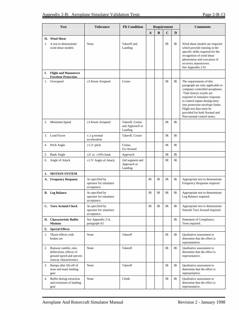
Appendix 2-B: Aeroplane Simulator Validation Tests Page 2-B-13
Aeroplane And Rotorcraft Simulator Manual Revision 2 - January 1998
Test Tolerance Flt Condition Requirement Comments
A B C D H. Wind Shear
1. A test to demonstrate wind shear models
None Takeoff and Landing
IR IR Wind shear models are required which provide training in the specific skills required for the recognition of wind shear phenomena and execution of recovery manoeuvres. See Appendix 2-D.
I. Flight and Manoeuvre Envelope Protection
1. Overspeed ±5 Knots Airspeed
Cruise IR IR The requirements of this paragraph are only applicable to computer controlled aeroplanes. Time history results are required of simulator response to control inputs during entry into protection envelope limits. Flight test data must be provided for both Normal and Non-normal control states.
2. Minimum Speed ±3 Knots Airspeed Takeoff, Cruise and Approach or Landing
IR IR
3. Load Factor ±.1 g normal acceleration
Takeoff, Cruise IR IR
4. Pitch Angle ±1.5° pitch Cruise, Go-Around
IR IR
5. Bank Angle ±2° or ±10% bank Approach IR IR
6. Angle of Attack ±1.5° Angle of Attack 2nd segment and Approach or Landing
IR IR
3. MOTION SYSTEM
A. Frequency Response As specified by operator for simulator acceptance.
IR IR IR IR Appropriate test to demonstrate Frequency Response required.
B. Leg Balance As specified by operator for simulator acceptance.
IR IR IR IR Appropriate test to demonstrate Leg Balance required.
C. Turn Around Check As specified by operator for simulator acceptance.
IR IR IR IR Appropriate test to demonstrate Smooth Turn Around required.
D. Characteristic Buffet Motions
See Appendix 2-A, paragraph 4.f.
IR Statement of Compliance. Tests required.
E. Special Effects
1. Thrust effects with brakes set
None Takeoff IR IR Qualitative assessment to determine that the effect is representative.
2. Runway rumble, oleo deflections, effects of ground speed and uneven runway characteristics
None Takeoff IR IR Qualitative assessment to determine that the effect is representative.
3. Bumps after lift-off of nose and main landing gear
None Takeoff IR IR Qualitative assessment to determine that the effect is representative.
4. Buffet during retraction and extension of landing gear
None Climb IR IR Qualitative assessment to determine that the effect is representative.
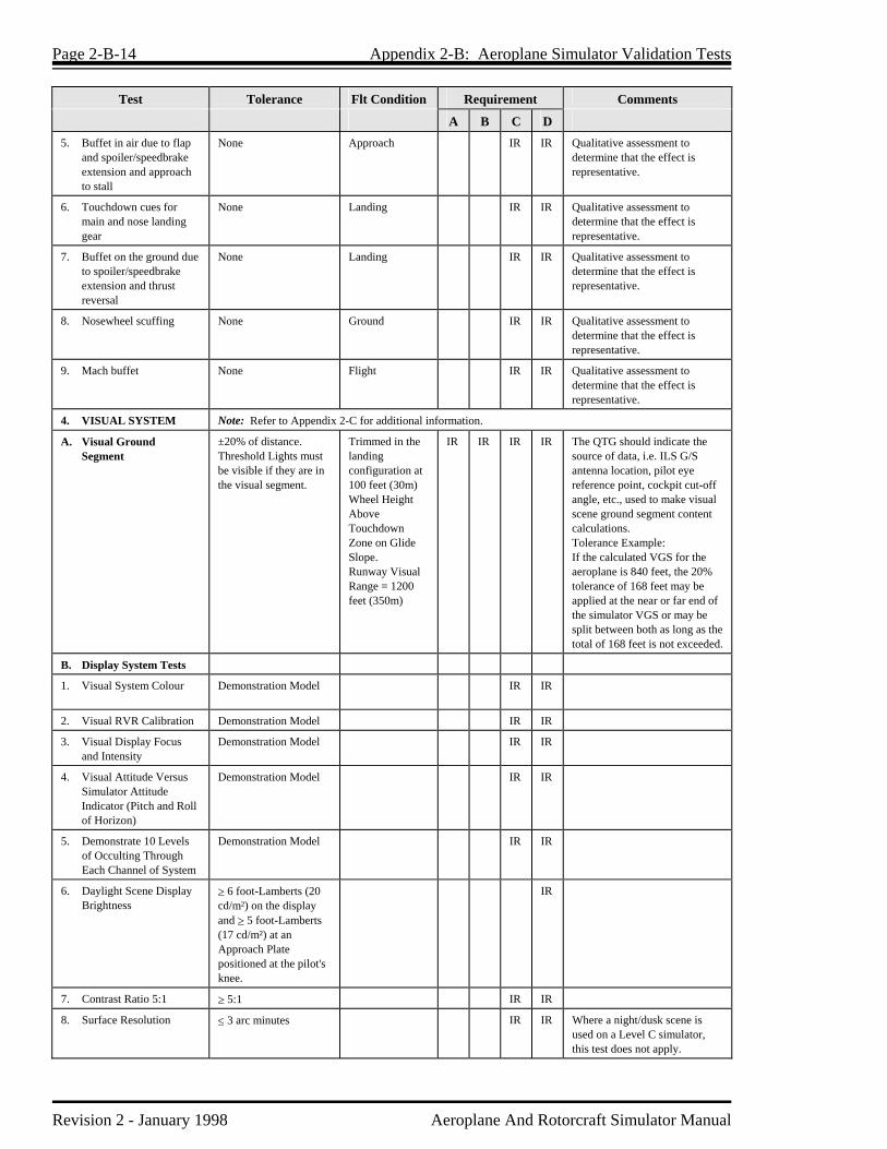
Page 2-B-14 Appendix 2-B: Aeroplane Simulator Validation Tests
Revision 2 - January 1998 Aeroplane And Rotorcraft Simulator Manual
Test Tolerance Flt Condition Requirement Comments
A B C D 5. Buffet in air due to flap
and spoiler/speedbrake extension and approach to stall
None Approach IR IR Qualitative assessment to determine that the effect is representative.
6. Touchdown cues for main and nose landing gear
None Landing IR IR Qualitative assessment to determine that the effect is representative.
7. Buffet on the ground due to spoiler/speedbrake extension and thrust reversal
None Landing IR IR Qualitative assessment to determine that the effect is representative.
8. Nosewheel scuffing None Ground IR IR Qualitative assessment to determine that the effect is representative.
9. Mach buffet None Flight IR IR Qualitative assessment to determine that the effect is representative.
4. VISUAL SYSTEM Note: Refer to Appendix 2-C for additional information.
A. Visual Ground Segment
±20% of distance. Threshold Lights must be visible if they are in the visual segment.
Trimmed in the landing configuration at 100 feet (30m) Wheel Height Above Touchdown Zone on Glide Slope. Runway Visual Range = 1200 feet (350m)
IR IR IR IR The QTG should indicate the source of data, i.e. ILS G/S antenna location, pilot eye reference point, cockpit cut-off angle, etc., used to make visual scene ground segment content calculations. Tolerance Example: If the calculated VGS for the aeroplane is 840 feet, the 20% tolerance of 168 feet may be applied at the near or far end of the simulator VGS or may be split between both as long as the total of 168 feet is not exceeded.
B. Display System Tests
1. Visual System Colour
Demonstration Model IR IR
2. Visual RVR Calibration Demonstration Model IR IR
3. Visual Display Focus and Intensity
Demonstration Model IR IR
4. Visual Attitude Versus Simulator Attitude Indicator (Pitch and Roll of Horizon)
Demonstration Model IR IR
5. Demonstrate 10 Levels of Occulting Through Each Channel of System
Demonstration Model IR IR
6. Daylight Scene Display Brightness
≥ 6 foot-Lamberts (20 cd/m²) on the display and ≥ 5 foot-Lamberts (17 cd/m²) at an Approach Plate positioned at the pilot's knee.
IR
7. Contrast Ratio 5:1 ≥ 5:1 IR IR
8. Surface Resolution ≤ 3 arc minutes IR IR Where a night/dusk scene is used on a Level C simulator, this test does not apply.

Appendix 2-B: Aeroplane Simulator Validation Tests Page 2-B-15
Aeroplane And Rotorcraft Simulator Manual Revision 2 - January 1998
Test Tolerance Flt Condition Requirement Comments
A B C D 9. Lightpoint Size ≤ 6 arc minutes IR IR This is equivalent to a light
point resolution of 3 arc minutes.
C. Visual Feature Recognition
Note: Within final picture resolution, the distances at which features are visible for tests (1) through (4) should not be less than those indicated in the specific test. Operators should indicate the light intensity level used for the test.
1. Runway Definition, Strobe Lights, Runway Edge White Lights and VASI Lights
5 statute miles (8 km) Approach from the runway
IR IR
2. Runway Centreline Lights
3 statute miles (5 km) Approach IR IR
3. Threshold Lights and Touchdown Zone Lights
2 statute miles (3km) Approach from the runway
IR IR
4. Runway Markings Night/Dusk scenes within range of landing lights. Day scene as required by 3 arc minutes resolution.
Approach IR IR
D. Visual Scene Content Note: For tests (1) through (10) the demonstration models can be a sampling of specific models used in the operator's training program or a generic airport model. A minimum of 3 specific airports is required.
1. Airport Runways and Taxiways
Demonstration Model Ground or Flight IR IR Qualitative Assessment.
2. Surface on Runways, Taxiways and Ramps
Demonstration Model Ground IR IR Qualitative Assessment.
3. Lighting for the runway in use
Demonstration Model Ground or Flight IR IR Qualitative Assessment. All lights associated with the test runway should be checked for appropriate colours (e.g. edge lights, centreline, touchdown zone, VASI, PAPI, REIL
4. Ramps and Terminal Buildings
Demonstration Model Ground IR IR
5. Dusk and Night Scene Capability
Demonstration Model Flight IR IR Qualitative Assessment. Dusk scene should include visible horizon and recognition of cultural features on the ground.
6. General Terrain characteristics and significant landmarks
Demonstration Model Flight IR IR Qualitative Assessment.
7. Capability to present Ground and Air Hazards such as another aeroplane crossing the active runway or Converging Airborne Traffic
Demonstration Model Ground or Flight IR IR Qualitative Assessment.

Page 2-B-16 Appendix 2-B: Aeroplane Simulator Validation Tests
Revision 2 - January 1998 Aeroplane And Rotorcraft Simulator Manual
Test Tolerance Flt Condition Requirement Comments
A B C D 8. Operational Visual
Scenes which portray representative physical relationships known to cause Landing Illusions on short Runways, Landing Approaches Over Water, Uphill or Downhill Runways, Rising Terrain on the Approach Path and Unique Topographic Features
Demonstration Model Approach and Landing
IR Qualitative Assessment. May be a generic airport model or specific airport(s).
9. Realistic Colour and Directionality of airport lighting
Demonstration Model Ground or Flight IR Qualitative Assessment.
10. Freedom from apparent quantization (aliasing)
Demonstration Model Ground or Flight IR IR Qualitative Assessment.
E. Weather Effects Note: For tests (1) through (8) specific airport models or generic airport models may be used. All models used for these tests must be available in the operator's approved training program. Weather effects described in tests (4) through (8) should be selectable via controls at the IOS such as cloud base, cloud effects and visibility (Kilometres/Statute Miles) and RVR (meters/feet).
1. Special weather representations of light, medium and heavy precipitation near a thunderstorm on takeoff, approach and landings at an altitude of 2000 ft (610m) above the airport surface and within a radius of 10 sm (16km) from the airport
Flight IR Qualitative Assessment.
2. Wet and Snow covered runway including runway lighting reflections for wet, partially obscured lights from snow or suitable alternative effects
Demonstration Model Ground IR Qualitative Assessment.
3. Weather Radar presentations in aeroplanes where radar information is presented on the pilot's navigational instruments. Radar returns should correlate to the visual scene
Demonstration Model Flight IR Qualitative Assessment.
4. Variable Cloud Density Demonstration Model Approach IR IR Qualitative Assessment.
5. Partial Obscuration of ground scenes: the effect of a scattered to broken cloud deck
Demonstration Model Approach IR IR Qualitative Assessment.
6. Gradual Breakout Demonstration Model Approach IR IR Qualitative Assessment. Visibility and cloud effects should be checked at and below an altitude of 2000 feet (610m) height above the airport and within a radius of 10 sm (16 km) from the airport.

Appendix 2-B: Aeroplane Simulator Validation Tests Page 2-B-17
Aeroplane And Rotorcraft Simulator Manual Revision 2 - January 1998
Test Tolerance Flt Condition Requirement Comments
A B C D 7. Patchy Fog Demonstration Model Approach or
Takeoff IR IR Qualitative Assessment.
8. The Effect of Fog on Airport Lighting
Demonstration Model Approach or Takeoff
IR IR Qualitative Assessment.
F. Flight Compatibility
1. Visual system compatibility with aerodynamic programming
Not Applicable Ground and Flight
IR IR IR
IR Qualitative tests to verify the latency, throughput and visual attitude versus simulator attitude tests.
2. Visual cues to assess sink rate and depth perception during landings
Not Applicable Approach and Landing
IR IR IR Qualitative tests to confirm that terrain features, surfaces on taxiways and ramps and other cultural features which provide cues for landing the aeroplane.
3. Accurate portrayal of environment relating to simulator attitudes
Not Applicable Flight IR IR IR IR
5. SOUND SYSTEM
A. Significant cockpit sounds which result from pilot actions corresponding to those of the aeroplane
Not Applicable Flight and Ground
IR IR Qualitative Assessment. Statement Of Compliance or Demonstration of representative sounds.
B. Sound of precipitation, windshield wipers and other significant aeroplane noises perceptible to the flight crew during normal operations and the sound of a crash related in some logical manner to landing in an unusual attitude or in excess of the structural gear limitations of the aeroplane
Not Applicable Flight and Ground
IR IR Statement Of Compliance or Demonstration of representative sounds. Significant aeroplane noises should include noises such as engine, flap, gear and spoiler extension and retraction and thrust reversal to a comparable level as that found in the aeroplane.
C. Realistic amplitude and frequency of cockpit noises and sounds, including precipitation static and engine and airframe sounds. The sounds shall be coordinated with the weather representations required to be displayed in the visual scene
Not Applicable Flight and Ground
IR Test results must show a comparison of the amplitude and frequency content of the sounds.

Page 2-B-18 Appendix 2-B: Aeroplane Simulator Validation Tests
Revision 2 - January 1998 Aeroplane And Rotorcraft Simulator Manual
Test Tolerance Flt Condition Requirement Comments
A B C D 6. SIMULATOR
SYSTEMS
A. Visual, Motion and Cockpit Instrument Systems Response
Visual, Motion and Cockpit Instrument Systems Response to an abrupt pilot controller input, compared to aeroplane response for a similar input
OR Transport Delay
150 milliseconds or less after aeroplane response. 300 milliseconds or less after aeroplane response. 150 milliseconds or less after control movement. 300 milliseconds or less after control movement.
Takeoff, Cruise, Approach or Landing Takeoff, Cruise, Approach or Landing Pitch, Roll, Yaw Pitch, Roll, Yaw
IR IR
IR IR
IR IR
IR IR
One test is required in each axis (Pitch, Roll and Yaw) for each of the 3 conditions compared to aeroplane data for a similar input (total 9 tests). Visual change may start before motion response, but motion acceleration must occur before completion of visual scan of first video field containing different information. One test is required in each axis (total 3 tests). See Appendix 2-A, section 3, paragraph v.
B. Diagnostic Testing
1. A means for quickly and effectively testing simulator programming and hardware. This could include an automated system which could be used for conducting at least a portion of the tests in the QTG
IR IR
2. Self testing of simulator hardware and programming to determine compliance with Level B, C and D Simulator Requirements
IR
3. Diagnostic analysis as prescribed in FAR Part 121, App H, Level D (Phase III), Simulator Requirement No. 5
IR
4. Control Dynamics The characteristics of an aeroplane flight control system have a major effect on the handling qualities. A significant consideration in pilot acceptability of an aeroplane is the "feel" provided through the cockpit controls. Considerable effort is expended on aeroplane feel system design in order to deliver a system with which pilots will be comfortable and consider the aeroplane desirable to fly. In order for a simulator to be representative, it too must present the pilot with the proper feel; that of the respective aeroplane. This fact is recognized in FAR 121, Appendix H, Phase II (Level C), Simulator Requirement 10, which states: "Aircraft control feel dynamics shall duplicate the aeroplane simulated. This shall be determined by comparing a recording of the control feel dynamics of the simulator to aeroplane measurements in the takeoff, cruise and landing configuration".

Appendix 2-B: Aeroplane Simulator Validation Tests Page 2-B-19
Aeroplane And Rotorcraft Simulator Manual Revision 2 - January 1998
Recordings such as free response to an impulse or step function are classically used to estimate the dynamic properties of electromechanical systems. In any case, it is only possible to estimate the dynamic properties as a result of only being able to estimate true inputs and responses; therefore, it is imperative that the best possible data be collected since close matching of the simulator control loading system to the aeroplane systems is essential. The required control feel dynamic tests are described in 2.B. of the Table of Validation Tests of this Appendix. For initial and upgrade evaluations, it is required that control dynamic characteristics be measured at and recorded directly from the cockpit controls. This procedure is usually accomplished by measuring the free response of the controls using a step or pulse input to excite the system. The procedure must be accomplished in takeoff, cruise and landing flight conditions and configurations. For aeroplanes with irreversible control systems, measurements may be obtained on the ground if proper pitot-static inputs are provided to represent airspeeds typical of those encountered in flight. Likewise, it may be shown that for some aeroplanes, takeoff, cruise and landing configurations have like effects. Thus, one may suffice for another. If either or both considerations apply, engineering validation or aeroplane manufacturer rationale must be submitted as justification for ground tests or for eliminating a configuration. For simulators requiring static and dynamic tests at the controls, special test fixtures will not be required during initial and upgrade evaluations if the operator's QTG shows both test fixture results and the results of an alternate approach, such as computer plots which were produced concurrently and show satisfactory agreement. Repeat of the alternate method during the initial evaluation would then satisfy this test requirement. 5. Control Dynamics Evaluation The dynamic properties of control systems are often stated in terms of frequency, damping and a number of other classical measurements which can be found in texts on control systems. In order to establish a consistent means of validating test results for simulator control loading, criteria are needed that will clearly define the interpretation of the measurements and the tolerances to be applied. Criteria are needed for underdamped, critically and overdamped systems. In case of an underdamped system with very light damping, the system may be quantified in terms of frequency and damping. In critically damped or overdamped systems, the frequency and damping is not readily measured from a response time history; therefore, some other measurement must be used. For Levels C and D simulators, tests to verify that control feel dynamics represent the aeroplane must show that the dynamic damping cycles (free response of the controls) match that of the aeroplane within specified tolerances of damping. The method of evaluating the response is described below for the underdamped and critically damped cases. Underdamped Responses Two measurements are required for the period, the time to first zero crossing (in case a rate limit is present) and the subsequent frequency of oscillation. It is necessary to measure cycles on an individual basis in case there are non-uniform periods in the response. Each period will be independently compared to the respective period of the aeroplane control system and, consequently, will enjoy the full tolerance specified for that period. The damping tolerance should be applied to overshoots on an individual basis. Care should be taken when applying the tolerance to small overshoots since the significance of such overshoots becomes questionable. Only those overshoots larger than 5% of the total initial displacement should be considered significant. The simulator should show the same number of significant overshoots to

Page 2-B-20 Appendix 2-B: Aeroplane Simulator Validation Tests
Revision 2 - January 1998 Aeroplane And Rotorcraft Simulator Manual
within 1 when compared against the aeroplane data. This procedure for evaluating the response is illustrated in Figure 1. Critically Damped and Overdamped Response Due to the nature of critically damped responses (no overshoots), the time to reach 90% of the steady state (neutral point) value should be the same as the aeroplane within ±10%. The simulator response should be critically damped also. Figure 2 illustrates the procedure. Tolerances The following table summaries the tolerances, T. See Figures 1 and 2 for an illustration of the referenced measurements.
T(P0) T(P1) T(Pn) T(An) T(Ad) Overshoots
±10% of P0 ±20% of P1 ±10% of Pn ±10% of A1, ±20% of Subsequent Peaks ±5% of Ad ±1
Alternate Method for Control Dynamics One aeroplane manufacturer has proposed, and TC accepts, an alternate means for dealing with control dynamics. The method applies to aeroplanes and artificial feel systems. Instead of free response measurements, the system would be validated by measurements of control force and rate of movement. For each axis of pitch, roll and yaw, the control shall be forced to its maximum extreme position for the following distinct rates. These tests shall be conducted at typical taxi, takeoff, cruise and landing configuration.
a) Static Test - Slowly move the control such that approximately 100 seconds are required to achieve a full sweep.
b) Slow Dynamic Test - Achieve a full sweep in approximately 10 seconds.
c) Fast Dynamic Test - Achieve a full sweep in approximately 4 seconds.
Note: Dynamic sweeps may be limited to forces not exceeding 100 lbs. Tolerances
a) Static Test ─ As per items in 2.B. of this Appendix.
b) Dynamic Test ─ 2 lbs or 10% on dynamic increment above static test. TC is open to alternative means such as the one described above. Such alternatives must, however, be justified and appropriate to the application. For example, the method described here may not apply to all manufacturers' systems and certainly not to aeroplanes with reversible control systems. Hence, each case must be considered on its own merit on an ad hoc basis. Should TC find that alternative methods do not result in satisfactory simulator performance, then more conventionally

Appendix 2-B: Aeroplane Simulator Validation Tests Page 2-B-21
Aeroplane And Rotorcraft Simulator Manual Revision 2 - January 1998
accepted methods must be used.
Figure 1 Under-Damped Step Response
T(P0) T(P1)
Ad
T(A1)
P0 P1
T(Ad)
A1
P = PeriodA = AmplitudeT(P) = Tolerance Applied to PeriodT(A) = Tolerance Applied to Amplitude
Displacement Versus Time
Figure 2 Critically Damped Step Response
Ad
P0
T(P0)
90% of Ad
Displacement Versus Time

Page 2-B-22 Appendix 2-B: Aeroplane Simulator Validation Tests
Revision 2 - January 1998 Aeroplane And Rotorcraft Simulator Manual
6. Ground Effect During landing and takeoff, aeroplanes operate for brief time intervals close to the ground. The presence of the ground significantly modifies the air flow past the aeroplane and, therefore, changes the aerodynamic characteristics. The close proximity of the ground imposes a barrier which inhibits the downward flow normally associated with the production of lift. The downwash is a function of height with the effects usually considered to be negligible above a height of approximately one wingspan. There are three main effects of the reduced downwash:
a) a reduction in downwash angle at the tail for a conventional configuration;
b) an increase in both wing and tail lift because of changes in the relationship of lift coefficient to angle of attack (increase in lift curve slope); and
c) a reduction in the induced drag.
Relative to out-of-ground effect flight (at a given angle of attack), these effects result in higher lift in ground effect and less power required for level flight. Because of the associated effects on stability, they also cause significant changes in elevator (or stabilator) angle to trim and stick (column) forces required to maintain a given lift coefficient in level flight near the ground. For a simulator to be used for takeoff and in particular landing credit, it must faithfully reproduce the aerodynamic changes which occur in ground effect. The parameters chosen for simulator validation must obviously be indicative of these changes. The primary validation parameters for longitudinal characteristics in ground effect are: a) elevator or stabilator angle to trim; b) power (thrust) required for level flight (PLF); c) angle of attack for a given lift coefficient; d) altitude/height; and e) airspeed. This listing of parameters assumes that the ground effect data is acquired by tests during "fly-bys" at several altitudes in and out of ground effect. The test altitudes should, as a minimum, be at 10%, 30% and 70% of the aeroplane wingspan and one altitude out of ground effect, e.g. 150% of wingspan. Level fly-bys are required for Level D, but not for Levels C and Level B. They are, however, acceptable for all levels. If, in lieu of the level fly-by method for Levels B and C, other methods such as shallow glidepath approaches to the ground maintaining a chosen parameter constant are proposed, then additional validation parameters are important. For example, if constant attitude shallow approaches are chosen as the test manoeuvre, pitch attitude and flight path angle are additional necessary validation parameters. The selection of the test method and procedures to validate ground effect is at the option of the organization performing the flight tests, however, rationale must be provided to conclude that the tests performed do indeed validate the ground-effect model.

Appendix 2-B: Aeroplane Simulator Validation Tests Page 2-B-23
Aeroplane And Rotorcraft Simulator Manual Revision 2 - January 1998
The allowable longitudinal parameter tolerances for validation of ground effect characteristics are:
Elevator or Stabilator Angle Power for Level Flight (PLF) Angle of Attack Altitude/Height Airspeed Pitch Attitude
±1° ±5% ±1° ±10% or ±5_ (1.5m) ±3 Knots ±1°
The lateral-directional characteristics are also altered by ground effect. Because of the above-mentioned changes in lift curve slope, roll damping, as an example, is affected. The change in roll damping will affect other dynamics modes usually evaluated for simulator validation. In fact, Dutch-roll dynamics, spiral stability and roll rate for a given lateral control input are altered by ground effect. Steady heading sideslip will also be affected. These effects must be accounted for in the simulator modelling. Several tests such as "crosswind landing", "one engine inoperative landing" and "engine failure on takeoff" serve to validate lateral-directional ground effect since portions of them are accomplished while transiting altitudes at which ground effect is an important factor.

Aeroplane And Rotorcraft Simulator Manual Revision 2 - January 1998
Appendix 2-C Functions and Subjective Tests 1. Discussion Functional and subjective tests of simulator characteristics and systems operation will be evaluated at each flight crew member position. As appropriate, these shall include the cockpit check, system operation, normal, abnormal and emergency procedures using the operator's operating procedures and check lists. Initial evaluation shall include functional checks from this Appendix as appropriate. If required, TC may elect to focus on simulator operation during a special aspect of an operator's training program during the functional check portion of a recurrent evaluation. Such a functional evaluation may include a portion of a LOFT scenario or special emphasis items within the operator's training program. Unless directly related to a requirement for the current certification level, the results of such an evaluation would not affect the simulator's current status. Operational principal navigation systems, including but not limited to, Electronic Flight Instrument Systems (EFIS), Flight Management Systems (FMS), Global Positioning System (GPS) and Initial Navigation Systems (INS) will be evaluated if installed. The ground and flight manoeuvres which shall be evaluated, as appropriate to the level of the simulator and the visual and special effects evaluations, are in the following table. Manoeuvres and procedures are included to address some features of advanced technology aeroplanes and innovative training programmes. For example, "high angle of attack manoeuvring" is included to provide an alternative to "approach to stalls". Such an alternative is necessary for aeroplanes employing flight envelope limiting technology. All systems functions will be assessed for normal and, where appropriate, alternate operations. Normal, abnormal and emergency procedures associated with a flight phase will be assessed during the evaluation of manoeuvres or events within that flight phase. Systems are listed separately under "any flight phase" to assure appropriate attention to system checks. 2. Table of Functions and Subjective Tests
Simulator Level
A B C D
1. FUNCTIONS AND MANOEUVRES A. PREPARATION FOR FLIGHT
1. Pre-flight. Accomplish a functions check of all switches, indicators, systems and equipment at all crew members' and instructors' stations and determine that the cockpit design and functions are identical to that of the aeroplane simulated.
x x x x
B. SURFACE OPERATIONS (PRE-TAKE-OFF)
1. Engine Start (a) Normal Start (b) Alternate Start Procedure (cross bleed, battery, etc.) (c) Abnormal Starts and Shutdowns (hot start, hung start, etc.)
x x x x
2. Pushback/Powerback x x x

Page 2-C-2 Appendix 2-C: Functions and Subjective Tests
Revision 2 - January 1998 Aeroplane And Rotorcraft Simulator Manual
Simulator Level
A B C D
3. Taxi (a) Thrust Response (b) Power Lever Friction (c) Ground Handling (d) Nosewheel Scuffing (e) Brake operation (normal and alternate/emergency) (f) Brake Fade (if applicable) (g) Other
x x x x
C. TAKE-OFF
1. Normal (a) Parameter Relationships (b) Acceleration Characteristics (c) Nosewheel and Rudder Steering (d) Crosswind (Maximum Demonstrated) (e) Special Performance (f) Instrument Take-off (g) Landing Gear, Wing Flap, Leading Edge Device Operation (h) Other
x x x x
2. Abnormal/Emergency (a) Rejected take-off (b) Rejected Special Performance (c) With failure of most critical engine at most critical point along take-off path (take-off continued) (d) With Windshear (e) Flight Control System Failure Modes (f) Other
x x x x
D. INFLIGHT OPERATION
1. Climb (a) Normal (b) One Engine Inoperative (c) Other
x x x x
2. Cruise (a) Performance Characteristics (speed versus power) (b) Turns With/Without Spoilers (speed brake) Deployed (c) High Altitude Handling (d) High Speed Handling (e) Mach Tuck and Trim, Overspeed Warning (f) Normal and Steep Turns (g) Performance Turns (h) Approach to Stalls (stall warning, buffet and g-break - cruise, take-off, approach and landing) (i) High Angle of Attack Manoeuvre (cruise, take-off, approach and landing) (j) Inflight Engine Shutdown and Restart (k) Manoeuvring with One Engine Inoperative (l) Special Flight Characteristics (m) Manual Flight Control Reversion (n) Flight Control System Failure Modes (o) Other
x x x x
3. Descent (a) Normal (b) Maximum Rate (c) Manual Flight Control Reversion (d) Flight Control System Failure Modes (e) Other
x x x x

Appendix 2-C: Functions and Subjective Tests Page 2-C-3
Aeroplane And Rotorcraft Simulator Manual Revision 2 - January 1998
Simulator Level
A B C D
E. APPROACHES
1. Non-Precision (a) Manoeuvring with All Engines Operating (b) Landing Gear, Operation of Flaps and Speed Brake (c) All Engines Operating (d) One or More Engines Inoperative (e) Approach Procedures • NDB • VOR, RNAV, TACAN • DME ARC • LOC/BC • AZI, LDA, LOC, SDF • GPS (f) Missed Approach • All Engines Operating • One or More Engines Inoperative (as applicable)
x x x x
2. Precision (a) PAR (b) DGPS (c) ILS • Normal • Engine(s) Inoperative • Category I Published Approach - Manually controlled with and without flight director to 100 ft. (30m) below Category I
minima - With Crosswind (maximum demonstrated) - With Windshear • Category II Published Approach - Auto-coupled, auto-throttle, auto-land - All engines operating missed approach • Category III Published Approach - With minimum/ standby electrical power - With generator failure - With 10 Knot tailwind - With 10 Knot crosswind - With Rollout - One engine inoperative
x x x x
3. Visual (a) Abnormal Wing Flaps/Slats (b) Without Glide Slope Guidance
x x x x
F. VISUAL SEGMENT AND LANDING
1. Normal (a) Crosswind (maximum demonstrated) (b) From VFR Traffic Pattern (c) From Non-Precision Approach (d) From Precision Approach (e) From Circling Approach
1
x
x x x x x
x x x x x
x x x x x
1 Simulators with visual systems which permit completing a circling approach may be approved for that particular circling
approach procedure.

Page 2-C-4 Appendix 2-C: Functions and Subjective Tests
Revision 2 - January 1998 Aeroplane And Rotorcraft Simulator Manual
Simulator Level
A B C D
2. Abnormal/Emergency (a) Engine(s) Inoperative (b) Rejected (c) With Windshear (d) With Standby (minimum electrical/hydraulic) Power (e) With Longitudinal Trim Malfunction (f) With Lateral-Directional Trim Malfunction (g) With Loss of Flight Control Power (manual reversion) (h) With Worst Case Failure of Flight Control System (most significant degradation of fly-by-wire
system which is not extremely improbable) (i) Other Flight Control System Failure Modes as Dictated by Training Program (j) Other
x x x x
G. SURFACE OPERATIONS
1. Landing Roll and Taxi (a) Spoiler Operation (b) Reverse Thrust Operation (c) Direction Control and Ground Handling, Both With and Without Reverse Thrust (d) Reduction of Rudder Effectiveness With Increased Reverse Thrust (rear pod-mounted engines) (e) Brake and Anti-Skid Operation with Dry, Wet and Icy Conditions (f) Engine Shutdown and parking - engine and systems operations - parking brake operation (g) Other
x x x
H. ANY FLIGHT PHASE
1. Aeroplane and Powerplant System Operation (a) Air Conditioning and Pressurization (b) Anti-icing/de-icing (c) Auxiliary Powerplant (d) Communications (e) Electrical (f) Fire Detection and Suppression (g) Flaps (h) Flight Controls (i) Fuel and Oil (j) Hydraulic (k) Landing Gear (l) Oxygen (m) Pneumatic (n) Powerplant (o) Pressurization
x x x x
2. Flight Management and Guidance Systems (a) Airborne Radar (b) Automatic Landing Aids (c) Autopilot (d) Collision Avoidance System (e) Flight Control Computers (f) Flight Data Displays (g) Flight Management Computers (h) Head-Up Displays (i) Navigation Systems (j) Stall Warning/Avoidance (k) Stability and Control Augmentation (l) Windshear Avoidance Equipment
x x x x
3. Airborne Procedures (a) Holding (b) Air Hazard Avoidance (c) Windshear
x x x
x
x
x

Appendix 2-C: Functions and Subjective Tests Page 2-C-5
Aeroplane And Rotorcraft Simulator Manual Revision 2 - January 1998
Simulator Level
A B C D
4. Engine Shutdown and Parking (a) Engine and Systems Operation (b) Parking Brake Operation
x x x x
2. VISUAL SYSTEM 1. Accurate Portrayal of Environment Relating to Simulator Attitudes x x x x
2. With final picture resolution, the distances at which runway features are visible should not be less than those listed below. Distances are measured from runway threshold to an aeroplane aligned with the runway on an extended 3° glide slope.
(a) Runway Definition, Strobe Lights, Approach Lights, Runway Edge White Lights and VASI Lights
from 5 Statute Miles (8 Kilometres) of the Runway Threshold (b) Runway Centreline Lights and Taxiway Definition from 3 Statute Miles (5 Kilometres) (c) Threshold Lights and Touchdown Zone Lights from 2 Statute Miles (3 Kilometres) (d) Runway Markings within Range of Landing Lights for Night Scenes (as required by 3 arc minute
resolution on day scenes)
x x x x
3. Representative Airport Scene Content Including: (a) Airport Runways and Taxiways (b) Runway Definition • Runway Surface and markings • Lighting for the runway in use including runway edge and centreline lighting, touchdown zone,
VASI and approach lighting of appropriate colours and taxiway lights
x x x x
4. Operational Landing Lights x x x x
5. Instructor Controls of: (a) Cloud base (b) Visibility in Statute Miles (Km) and RVR in Feet (Meters) (c) Airport Selection (d) Airport Lighting
x x x x
6. Visual System Comparability with Aerodynamic Programming x x x x
7. Visual Cues to Assess Sink Rates and Depth Perception During Landings (a) Surface on Taxiways and Ramps (b) Terrain Features
x x x
8. Dusk and Night Visual Scene Capability x x
9. Minimum of Three Specific Airport Scenes (a) Surfaces on Runways, Taxiways and Ramps (b) Lighting of Appropriate Colour for all Runways Including Runway Edge, Centreline, VASI and
Approach Lighting for the Runway in use and Airport Taxiway Lighting (c) Ramps and Terminal Buildings Which Correspond to an Operator's Line Oriented Flight Training
(LOFT) Scenarios
x x
10. General Terrain characteristics and significant landmarks x x
11. At and below 2,000 feet (610m) height above the airport and within a 10 mile (16.1 kilometre) radius of the airport, weather representations, including the following:
(a) Variable Cloud Density (b) Partial Obscuration of Ground Scenes (the effect of a scattered to broken cloud deck) (c) Gradual Break Out (d) Patchy Fog (e) The Effect of Fog on Airport Lighting
x x
12. A Capability to Present Ground and Air Hazards Such as Another Aeroplane Crossing the Active Runway or Converging Airborne Traffic
x x
13. Operational Visual Scenes Which Portray Representative Physical Relationships Known to Cause Landing Illusions Such as Short Runways, Landing Approaches Over Water, Uphill or Downhill Runways, Rising Terrain on the Approach Path and Unique Topographic Features
x
14. Special Weather Representations of which include the sound, visual and motion effects of entering light, medium and heavy precipitation near a thunder storm on take-off, approach and landings at and below an altitude of 2,000 feet (610m) above the airport surface and within a radius of 10 miles (16 kilometres) from the airport
x

Page 2-C-6 Appendix 2-C: Functions and Subjective Tests
Revision 2 - January 1998 Aeroplane And Rotorcraft Simulator Manual
Simulator Level
A B C D
15. Wet and Snow-Covered Runways Including Runway Lighting Reflections for Wet, Partially Obscured Lights for Snow or Suitable Alternative Effects
x
16. Realistic Colour and Directionality of Airport Lighting x
17. Weather Radar Presentation in Aeroplanes Where Radar Information is Presented on the Pilot's Navigation Instruments (Radar returns should correlate to the visual scene)
x
18. Freedom from Apparent Quantization (Aliasing) x
3. SPECIAL EFFECTS 1. Runway Rumble, Oleo Deflections, Effects of Ground Speed and Uneven Runway Characteristics x x x
2. Buffets on the Ground due to Spoiler/Speedbrake Extension and Thrust Renewal x x x
3. Bumps after Lift -Off of Nose and Main Gear x x x
4. Buffet During Extension and Retraction of Landing Gear x x x
5. Buffet in the Air Due to Flap and Spoiler/Speedbrake Extension and Approach-to-Stall Buffet x x x
6. Touchdown Cues for Main and Nose Gear x x x
7. Nosewheel Scuffing x x x
8. Thrust Effect with Brakes Set x x x
9. Mach Buffet x x x
10. Representative Brake and Tire Failure Dynamics (including anti-skid) and Decreased Brake Efficiency Due to High Brake Temperatures Based on Aeroplane Related Data
These representations should be realistic enough to cause pilot identification of the problem and
implementation of appropriate procedures. Simulator pitch, side loading and directional control characteristics should be representative of the aeroplane.
x x
11. Sound of Precipitation and Significant Aeroplane Noises Perceptible to the Pilot during Normal Operations and the Sound of a Crash When the Simulator is Landed in Excess of Landing Gear Limitations.
Significant aeroplane noises should include noises such engine, flap, gear and spoiler extension and
retraction and thrust reversal to a comparable level as that found in the aeroplane. The sound of a crash should be related in some logical manner to landing in an unusual attitude or in excess of the structural gear limitations of the aeroplane.
x x
12. Effects of Airframe Icing x x

Aeroplane And Rotorcraft Simulator Manual Revision 2 - January 1998
Appendix 2-D Windshear Qualification 1. Applicability This appendix applies to all simulators used for low-altitude windshear flight training. 2. Statement of Compliance A statement of compliance (SOC) is required to include the following: a) Documentation that the aerodynamic model is based on aeroplane data supplied by the aeroplane
manufacturer, or other named source, and that any change to environmental wind parameters, including variances in those parameters for windshear conditions, once inserted for computations, should result in the correct simulated performance; and
b) Examples, where environmental wind parameters are currently evaluated in the simulator (such as
crosswind take-off, crosswind approach and crosswind landing). 3. Qualification Basis The addition of windshear programming to a simulator in order to comply with the qualification for required windshear training does not change the original qualification basis of the simulator. 4. Models The windshear models installed in the simulator software that will be used for qualification evaluation must do the following: a) Provide cues necessary for recognition of the onset of a windshear phenomena and potential
performance degradation that would require a pilot to initiate recovery procedures. The cues must include one or more of the following, as may be appropriate —
(1) rapid airspeed change of at least +15 knots (kt), (2) stagnation of airspeed during the take-off roll, (3) rapid vertical speed change of at least +500 feet per minute (fpm), and/or (4) rapid pitch change of at least +5°; b) Be adjustable in intensity (or other parameter to achieve the desired effect) so that after encountering
and recognizing the windshear, and with the application of recommended procedures for escape from such a windshear, the following results may be achieved:
(1) the performance capability of the simulated aeroplane permits the pilot to maintain a satisfactory
flight path, or (2) the performance capability of the simulated aeroplane does not permit the pilot to maintain a
satisfactory flight path (crash); and

Page 2-D-2 Appendix 2-D: Windshear Qualification
Revision 2 - January 1998 Aeroplane And Rotorcraft Simulator Manual
c) Be available for use in the approved windshear flight training program. The means used to accomplish the "non-survivable" scenario of paragraph 4.b)(2), which involves operational elements of the simulated aeroplane, must reflect parameters which fall within the dispatch limitations of the aeroplane.
5. Tests a) The operator should identify two of the required training windshear models (one take-off and one
approach) to be demonstrated for Qualification Test Guide (QTG) purposes and should define the wind components of these two models for the survivable scenario. This definition should be presented in graphical format so that all components of the windshear are shown, including initiation point, variance in magnitude, and either time or distance correlation as may be appropriate. The simulator must be operated at the same gross weight, aeroplane configuration, and initial airspeed in both of the following situations for the two models selected (total of four tests):
(1) through calm air, and (2) through the selected survivable windshear; b) In each of these four situations, at an "initiation point" (that point being where the onset of windshear
conditions is, or would have been recognized, depending on the test being run), the recommended procedures for windshear recovery shall be applied, and the results shall be recorded, as specified in paragraph 6. These recordings shall be made without the presence of programmed random turbulence and, for the purposes of this testing, it is recommended, although not required, they be flown by means of the simulator's auto-drive function (for those simulators that have auto-drive capability) during the tests. Turbulence which results from the windshear model is to be expected, and no attempt may be made to neutralize turbulence from this source.
6. Recording Parameters a) In each of the four QTG cases, an electronic recording (time history) must be made of the following
parameters: (1) indicated or calibrated airspeed, (2) indicated vertical speed, (3) pitch attitude, (4) indicated or radio altitude, (5) angle of attack, and (6) elevator position; Note: Engine data (thrust, N1 or throttle position) and wind magnitudes must be included for
each of the four QTG cases.
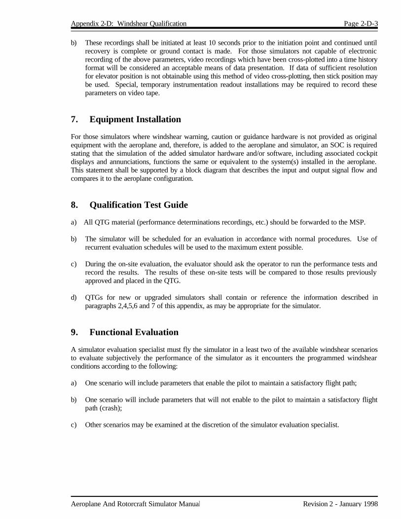
Appendix 2-D: Windshear Qualification Page 2-D-3
Aeroplane And Rotorcraft Simulator Manual Revision 2 - January 1998
b) These recordings shall be initiated at least 10 seconds prior to the initiation point and continued until recovery is complete or ground contact is made. For those simulators not capable of electronic recording of the above parameters, video recordings which have been cross-plotted into a time history format will be considered an acceptable means of data presentation. If data of sufficient resolution for elevator position is not obtainable using this method of video cross-plotting, then stick position may be used. Special, temporary instrumentation readout installations may be required to record these parameters on video tape.
7. Equipment Installation For those simulators where windshear warning, caution or guidance hardware is not provided as original equipment with the aeroplane and, therefore, is added to the aeroplane and simulator, an SOC is required stating that the simulation of the added simulator hardware and/or software, including associated cockpit displays and annunciations, functions the same or equivalent to the system(s) installed in the aeroplane. This statement shall be supported by a block diagram that describes the input and output signal flow and compares it to the aeroplane configuration. 8. Qualification Test Guide a) All QTG material (performance determinations recordings, etc.) should be forwarded to the MSP. b) The simulator will be scheduled for an evaluation in accordance with normal procedures. Use of
recurrent evaluation schedules will be used to the maximum extent possible. c) During the on-site evaluation, the evaluator should ask the operator to run the performance tests and
record the results. The results of these on-site tests will be compared to those results previously approved and placed in the QTG.
d) QTGs for new or upgraded simulators shall contain or reference the information described in
paragraphs 2,4,5,6 and 7 of this appendix, as may be appropriate for the simulator. 9. Functional Evaluation A simulator evaluation specialist must fly the simulator in a least two of the available windshear scenarios to evaluate subjectively the performance of the simulator as it encounters the programmed windshear conditions according to the following: a) One scenario will include parameters that enable the pilot to maintain a satisfactory flight path; b) One scenario will include parameters that will not enable to the pilot to maintain a satisfactory flight
path (crash); c) Other scenarios may be examined at the discretion of the simulator evaluation specialist.

Aeroplane And Rotorcraft Simulator Manual Revision 2 - January 1998
Chapter 3 Rotorcraft Simulators 3.1 Classification System 3.1.1 There are three levels of rotorcraft simulators: Levels B, C and D, with Level D simulators
being the most sophisticated. The more sophisticated the simulator, the more training and checking may be approved for that simulator. Procedures for applying for approval of a rotorcraft simulator are identical for each level. The qualification procedure and approved standards for rotorcraft simulators in this Chapter are based on FAA Advisory Circular 120-63.
3.2 Simulator Evaluation Program 3.2.1 In order to ensure an adequate transfer of learning and behaviour from the simulator to the
rotorcraft, the simulator shall be evaluated in each of the areas critical to the accomplishment of the flight crew member evaluation process. This includes evaluating the simulator's performance and handling qualities fidelity in the areas of pre-flight, control checks, taxi, take-off, climb, cruise, descent, approach, hover, landing and certain additional requirements depending on the sophistication of the rotorcraft simulated. The simulator's motion system and visual system will also need to be evaluated to ensure their proper operation. Instructor controls shall be operational to the extent necessary to assure completion of the tests required for initial approval.
3.2.2 It is desirable to evaluate the simulator as objectively as possible; however, pilot acceptance is
also an important consideration in the evaluation process. Therefore, evaluation of a simulator involves two types of tests designed to show that it represents the rotorcraft with sufficient fidelity to conduct the amount of training or checking requested. These tests include functional tests from Appendix 3-C. Functional tests are designed to provide a basis for evaluating a simulator's capability to perform over a typical training period and to verify the operational fidelity of the simulator's controls, instruments and systems. They shall be performed by a TC pilot experienced in the rotorcraft and type rated if appropriate. Performance and handling qualities tests are designed to provide a quantitative validation of the simulator's fidelity. They objectively compare simulator and rotorcraft performance within a specified tolerance. Each of the two types of tests is designed to complement the other and be supportive of required training objectives.
3.2.3 Tolerances listed in Appendix 3-B should not be confused with design tolerances specified for
simulator manufacture. Performance and handling qualities tolerances are maximum acceptable deviations of measured simulator parameters from the like rotorcraft parameters to assure adequate representation of the rotorcraft.
3.3 Initial Evaluations 3.3.1 An operator desiring initial or upgrade evaluation for a simulator must submit a request in writing
to the MSP or appropriate regional office. The request shall contain a statement certifying that the operator's QTG, that the simulator meets all of the specifications of this part of the manual, that specific hardware and software configuration control procedures have been established, and that the pilot(s) designated by the operator confirm that it is representative of the rotorcraft in all system functions and performance and handling qualities. The request shall also show the current modification level of the operator's aircraft fleet and of the simulator to be evaluated.
→ Tentative evaluation dates shall not be established until the QTG has been reviewed by the MSP and determined to be in accordance with this Manual. Normally within 10 working days of receiving the QTG, the MSP will coordinate with the operator to set a mutually acceptable date for the evaluation. To avoid unnecessary delays, operators are encouraged to work closely with the MSP during the QTG development process prior to making formal application.

Page 3-2 Chapter 3: Rotorcraft Simulators
Revision 2 - January 1998 Aeroplane And Rotorcraft Simulator Manual
→ Evaluations will normally be conducted in the same sequence as the QTGs and evaluation
requests are received by the MSP. 3.3.2 The operator's QTG shall include the following: a) The performance tests and procedures for conducting the tests described in Appendix 3-B
of this Chapter. If appropriate, the QTG shall also address each requirement from Appendix 3-C which specifically relates to the simulator. The QTG shall include a Statement of Compliance for each feature which cannot be demonstrated by a specific objective test.
b) Rotorcraft data to support each test delineated in Appendix 3-B. Rotorcraft data
documents included in a QTG may be photographically reduced only if such reduction will not allow the graphic scaling or cause difficulties in scale interpretation.
c) Operator's simulator test results appropriately recorded to demonstrate simulator fidelity.
These results shall be easily compared to the supporting data by employing cross plotting, overlap or transparencies or other acceptable means. The test guide will then show the documented proof of compliance with the simulator objective tests in Appendix 3-B. In the case of a simulator upgrade, an operator shall run the tests for the current evaluation level. Test results offered in a test guide for a previous initial or upgrade evaluation shall not be offered to validate a simulator as part of a test guide offered for a succeeding phase. Simulator test results requiring a comparison of time histories of flight test data, or transparencies thereof, shall be clearly marked with appropriate reference points to ensure an accurate comparison between simulator and aircraft data with respect to time. Operators using line printers to record time histories shall clearly mark information taken from the line printer data sheet for cross-plotting in the rotorcraft data. The original recordings of simulator test results shall be inserted into a separate volume as a reference document of the QTG. The cross-plotting or other comparisons of the operator's simulator data to rotorcraft data is essential to verify simulator performance or handling qualities in each test. During an evaluation, TC will devote its time to detailed checking of selected tests from the QTG. The TC evaluation will therefore serve to validate the operator's simulator tests.
d) Rotorcraft data documents included in a QTG may be photographically reduced only if such
reduction will not alter the graphic scaling or cause difficulties in scale interpretation. Incremental scales on graphical presentations shall provide the resolution necessary for evaluation of the appropriate parameters shown in Appendix 3-B.
3.3.3 Following the initial or upgrade evaluation, a completed master QTG containing the following
shall be submitted to the MSP: a) Table of Contents; b) Reference page listing all verification data used; c) glossary of terms and symbols used in the test guide; and d) for each test included in the test guide: 1. the name of the test, 2. the test objective, 3. the test conditions, 4. the test procedures, 5. the recording procedure, 6. the tolerances allowed, and 7. the rotorcraft flight test data with evaluation results cross plotted on that data. 3.3.4 The original simulator test results of the operator's evaluation and TC evaluation shall be
submitted along with the master QTG under separate cover. The simulator test results shall be presented in a manner that is easily cross referenced to the data in the test guide.

Chapter 3: Rotorcraft Simulators Page 3-3
Aeroplane And Rotorcraft Simulator Manual Revision 2 - January 1998
3.3.5 A copy of the master QTG shall accompany the master QTG submitted. This copy will be retained for use in recurrent simulator evaluations. The master QTG shall be reviewed by the MSP prior to the first recurrent evaluation of the simulator.
3.3.6 All simulator initial evaluations and subsequent recurrent evaluations after the date of issue of
this manual will be conducted according to the guidance herein. 3.3.7 During evaluations, a sponsor’s current, line qualified or designated pilot and a sponsor’s or
operator’s simulator operator will be available to assist in the accomplishment of the functions and validation tests. TC type qualified personnel shall manipulate the controls during the TC evaluation with assistance from the sponsor’s pilot at the discretion of TC.
3.4 Recurrent Evaluations 3.4.1 For a simulator to retain its current status, it shall be evaluated on a recurring basis using the
currently approved QTG. Recurrent evaluations shall be accomplished every six months. Each recurrent evaluation shall be scheduled at eight hours and will consist of functional tests and the completion of approximately one half of the objective tests in the QTG. The goal is to complete each QTG annually.
3.4.2 In the interest of conserving simulator time, the following program alternatives to the normal
eight hour recurrent evaluation procedure are available to all operators: a) At least one half of all the performance tests will be performed and certified by operator
personnel between TC recurrent evaluations. Complete coverage will be required through two consecutive recurrent evaluations. These tests and results shall be reviewed by TC at the outset of each evaluation. The one half of the performance tests executed for each recurrent evaluation shall be accomplished evenly spaced throughout the six month period.
b) Twenty per cent of those tests conducted by the operator for each recurrent evaluation
shall then be selected and repeated by TC. c) Ten per cent of those tests not performed by the operator shall also be selected by TC for
execution during each recurrent evaluation.
Page 3-4 Chapter 3: Rotorcraft Simulators
Revision 2 - January 1998 Aeroplane And Rotorcraft Simulator Manual
d) Operators must notify the MSP in writing of their intent to enter the optional program. The test procedures above shall then be exercised at the next recurrent evaluation. If the above procedure can be accommodated with less than eight hours of simulator time, subsequent recurrent evaluations for that simulator will be planned for four hours, a reduction of 50 per cent from the eight hours normally required. The four hours includes non-programmed downtime such as correction of malfunctions. If the operators cannot extend the period, then the evaluation shall be terminated and rescheduled at a later date.
3.5 Special Evaluations 3.5.1 Between recurring evaluation, if deficiencies are discovered or it becomes apparent that the
simulator is not being maintained to initial evaluation tolerances, a special evaluation of the simulator may be scheduled by the MSP to confirm its performance.
3.5.2 The simulator will retain its status unless the MSP can no longer certify original simulator
performance criteria based on the special evaluation. The operator shall be advised if a deficiency is jeopardizing training requirements wherein arrangements shall be made to resolve the deficiency in the most effective manner.
3.6 Modification of Simulators, Motion and Visual Systems 3.6.1 Flexibility in software and hardware modification is necessary to correct previously undetected
discrepancies and to make necessary improvements. Strict discipline is essential to ensure that the simulator maintains its ability to duplicate the rotorcraft flight characteristics. Operators shall maintain configuration control systems for software and hardware to ensure the continued integrity of the simulator as qualified. The configuration control systems may be examined by TC on demand. The following procedures shall be followed to allow these changes without affecting the approval of the simulator:
a) Twenty-one calendar days before making changes to hardware or software which may
affect the performance or handling qualities of the rotorcraft simulator, a complete list of the proposed changes shall be provided to the MSP in writing including the dynamics related to the motion and visual systems and necessary updates to the QTG.
b) The proposed change shall be reviewed by the MSP in accordance with this Manual. If TC
does not object to the proposed change within 21 calendar days, the change may be made. c) An amended copy of the QTG pages affected by the change shall be provided to update the
QTG. d) TC may examine the supporting data or test the simulator, or both, to ensure that the fidelity
of the simulator has not been degraded. 3.7 Upgrading of Simulators, Motion and Visual Systems 3.7.1 Operators shall notify TC of simulator hardware and programming changes which are necessary
for upgrading a simulator to new motion or visual systems. 3.7.2 Changes to simulator hardware and programming which are required for simulator upgrade will
not affect the current status of the simulator unless an evaluation by TC shows that the change has had a detrimental effect on the simulator; however, new simulator motion or visual system upgrade modifications will require an evaluation of that system as part of the next recurrent evaluation of the simulator.
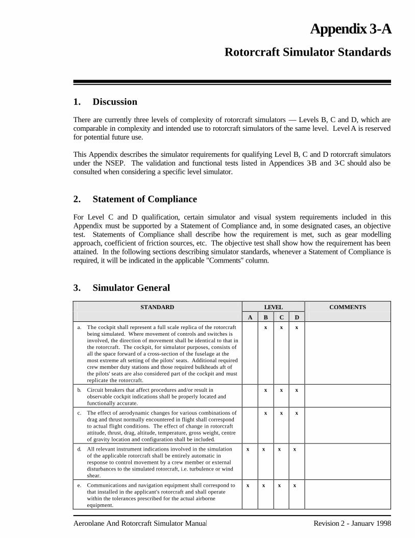
Aeroplane And Rotorcraft Simulator Manual Revision 2 - January 1998
Appendix 3-A Rotorcraft Simulator Standards 1. Discussion There are currently three levels of complexity of rotorcraft simulators — Levels B, C and D, which are comparable in complexity and intended use to rotorcraft simulators of the same level. Level A is reserved for potential future use. This Appendix describes the simulator requirements for qualifying Level B, C and D rotorcraft simulators under the NSEP. The validation and functional tests listed in Appendices 3-B and 3-C should also be consulted when considering a specific level simulator. 2. Statement of Compliance For Level C and D qualification, certain simulator and visual system requirements included in this Appendix must be supported by a Statement of Compliance and, in some designated cases, an objective test. Statements of Compliance shall describe how the requirement is met, such as gear modelling approach, coefficient of friction sources, etc. The objective test shall show how the requirement has been attained. In the following sections describing simulator standards, whenever a Statement of Compliance is required, it will be indicated in the applicable "Comments" column. 3. Simulator General
STANDARD LEVEL COMMENTS
A B C D
a. The cockpit shall represent a full scale replica of the rotorcraft being simulated. Where movement of controls and switches is involved, the direction of movement shall be identical to that in the rotorcraft. The cockpit, for simulator purposes, consists of all the space forward of a cross-section of the fuselage at the most extreme aft setting of the pilots' seats. Additional required crew member duty stations and those required bulkheads aft of the pilots' seats are also considered part of the cockpit and must replicate the rotorcraft.
x x x
b. Circuit breakers that affect procedures and/or result in observable cockpit indications shall be properly located and functionally accurate.
x x
x
c. The effect of aerodynamic changes for various combinations of drag and thrust normally encountered in flight shall correspond to actual flight conditions. The effect of change in rotorcraft attitude, thrust, drag, altitude, temperature, gross weight, centre of gravity location and configuration shall be included.
x x x
d. All relevant instrument indications involved in the simulation of the applicable rotorcraft shall be entirely automatic in response to control movement by a crew member or external disturbances to the simulated rotorcraft, i.e. turbulence or wind shear.
x x x x
e. Communications and navigation equipment shall correspond to that installed in the applicant's rotorcraft and shall operate within the tolerances prescribed for the actual airborne equipment.
x x x x

Page 3-A-2 Appendix 3-A: Rotorcraft Simulator Standards
Revision 2 - January 1998 Aeroplane And Rotorcraft Simulator Manual
STANDARD LEVEL COMMENTS
A B C D
f. In addition to the flight crew member stations, there shall be two suitable seats for the Instructor/Check Pilot and Transport Canada Inspector. The MSP will consider options to this standard based on unique cockpit configurations. These seats shall provide adequate vision to the pilot's panel and forward windows in visual system models. Observer seats need not represent those found in the rotorcraft but shall possess similar positive restraint devices.
x x x x
g. Simulator systems must simulate the applicable rotorcraft system operation, both on the ground and in flight. Three systems must be operative to the extent that normal, abnormal and emergency operating procedures appropriate to the simulator application can be accomplished.
x x x
h. Instructor controls shall be installed to enable the operator to control all required system variables and insert abnormal or emergency conditions into the rotorcraft systems.
x x x
i. Static control forces and degree of control travel shall correspond to that of the applicable rotorcraft. Control forces shall react in the same manner as in the rotorcraft under the same flight conditions.
x x x
j. Significant cockpit sounds which result from pilot actions corresponding to those of the rotorcraft.
x x x
k. Sound of precipitation windshield wiper and other significant rotorcraft noises perceptible to the pilot during normal operations and the sound of a crash when the simulator is landed in excess of landing gear limitations.
x x Statement of Compliance for Level D, appropriate weather related sounds shall be coordinated with the weather representations specified in Appendix 3-C, section 2, item 15.
l. Realistic amplitude and frequency of cockpit noises and sounds, including engine, transmission, rotor and airframe sounds.
x Tests required for noises and sounds that originate from the rotorcraft or rotorcraft systems.
m. Ground handling and aerodynamic programming to include: (1) ground effect - e.g. flare and touchdown from a running
landing as well as in ground effect (IGE) hover programming;
(2) ground reaction - reaction of the rotorcraft upon contact with the runway during landing to include strut deflections, tire friction, side forces and other appropriate data such as weight and speed necessary to identify the flight condition and configuration;
(3) ground handling characteristics - steering inputs to include crosswind, braking, thrust reversing, deceleration and turning radius.
x x x Statement of Compliance. Tests Required. Level B does not require hover programming.
n. Representative crosswind modelling and instructor controls for wind speed and direction.
x x x
o. Representative stopping and directional control forces for at least the following runway conditions based on rotorcraft related data for a running landing:
(1) dry; (2) wet; (3) icy; (4) patchy wet; and (5) patchy icy.
x
x
Statement of Compliance. Objective Test for 1. Functional check for 2, 3, 4 and 5. The subjective tolerance is interpreted to mean that the relationships among the tests are logical (e.g. "patchy icy" distances are less than "icy" distances) and that the performance can be rationalized against Flight Manual documented performance.
p. Representative brake and tire failure dynamics and decreased brake efficiency due to brake temperature based on rotorcraft related data.
x x Statement of Compliance. Tests required.

Appendix 3-A: Rotorcraft Simulator Standards Page 3-A-3
Aeroplane And Rotorcraft Simulator Manual Revision 2 - January 1998
STANDARD LEVEL COMMENTS
A B C D
q. Simulator computer capacity, accuracy, resolution and dynamic response sufficient for the level sought.
x x x Statement of Compliance.
r. Cockpit control dynamics which replicate the rotorcraft simulated. Free response of the controls shall match that of the rotorcraft within the tolerance given in Appendix 3-B. Initial and upgrade evaluation will include control free response (cyclic, collective and pedal) measurements recorded at the controls. The measured responses must correspond to those of the rotorcraft in ground operations, hover, climb, cruise and autorotation.
(1) For rotorcraft with irreversible control systems,
measurements may be obtained on the ground if proper pilot static inputs are provided to represent conditions typical of those encountered in flight. Engineering validation or rotorcraft manufacturer rationale will be submitted as justification to ground test or omit a configuration.
(2) For simulators requiring static and dynamic tests at the
controls, special test fixtures will not be required during initial evaluations if the operator's QTG shows both test fixture results and alternate test method results such as computer plots which were obtained concurrently. Repeat of the alternate method during the initial evaluation may then satisfy this test equipment.
x x Tests Required. See Appendix 3-B, section 4.

Page 3-A-4 Appendix 3-A: Rotorcraft Simulator Standards
Revision 2 - January 1998 Aeroplane And Rotorcraft Simulator Manual
STANDARD LEVEL COMMENTS
A B C D
s. (1) Relative responses of the motion system, visual system and cockpit instruments shall be coupled closely to provide integrated sensory cues. These systems shall respond to abrupt pitch, roll and yaw inputs at the pilot's position within 100/150 milliseconds of the time, but not before the time, when the rotorcraft would respond under the same conditions.
(2) Visual change may start before motion response, but motion
acceleration must occur before completion of visual scan of first video field containing different information. The test to determine compliance with these requirements should include simultaneously recording the analogue output from the pilot's cyclic, collective and pedals, the output from an accelerometer attached to the motion system platform located at an acceptable location near the pilots' seats, the output signal to the visual system display (including visual system analogue delays), and the output signal to the pilot's attitude indicator or an equivalent test approved by the Administrator. The test results in a comparison of a recording of the simulator's response to actual rotorcraft response data in hover (Levels C and D only), climb, cruise and autorotation. For rotorcraft response, acceleration in the appropriate rotational axis is preferred.
As an alternative, a transport delay test may be used to
demonstrate that the simulator systems do not exceed the specified limit of 100/150 milliseconds.
This test shall measure all the delay encountered by a step
signal migrating from the pilots' control though the control loading electronics and interfacing through all the simulation software modules in the correct order, using a handshaking protocol, finally through the normal output interfaces to the motion system, to the visual system and instrument displays. A recordable start time for the test should be provided by a pilot flight control input. The test mode shall permit normal computation time to be consumed and shall not alter the flow of information through the hardware/software system. The transport delay of the system is then the time between the control input and the individual system responses. It need only be measured once in each axis, being independent of flight conditions.
x
x
x
Tests required. For Level B, response must be within 150 milliseconds. For Levels C and D, response must be within 100 milliseconds.
t . Aerodynamic modelling which includes ground effect, effects of airframe icing (if applicable), aerodynamic interference effects between the rotor wake and the fuselage, influence of the rotor on control and stabilization systems and representations of non-linearities due to sideslip based on rotorcraft flight test data provided by the manufacturer.
x
u. A means for quickly and effectively testing simulator programming and hardware. This may include an automated system which could be used for conducting at least a portion of the tests in the QTG.
x x Statement of Compliance.
v. Self-testing for simulator hardware and programming to determine compliance with simulator performance tests as prescribed in Appendix 3-B. Evidence of testing must include simulator number, date, time, conditions, tolerances and appropriate dependent variables portrayed in comparison to the rotorcraft standard. Automatic flagging of "out -of-tolerance" situations is encouraged.
x Statement of Compliance. Tests Required.
w. Diagnostic analysis printouts of simulator malfunctions sufficient to determine compliance with the Simulator Component Inoperative Guide (SCIG). These printouts shall be retained by the operator between recurring TC simulator evaluations as part of the daily discrepancy log.
x Statement of Compliance.
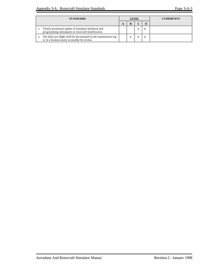
Appendix 3-A: Rotorcraft Simulator Standards Page 3-A-5
Aeroplane And Rotorcraft Simulator Manual Revision 2 - January 1998
STANDARD LEVEL COMMENTS
A B C D
x. Timely permanent update of simulator hardware and programming subsequent to rotorcraft modification.
x x
y. The daily pre-flight shall be documented in the maintenance log or in a location easily accessible for review.
x x x
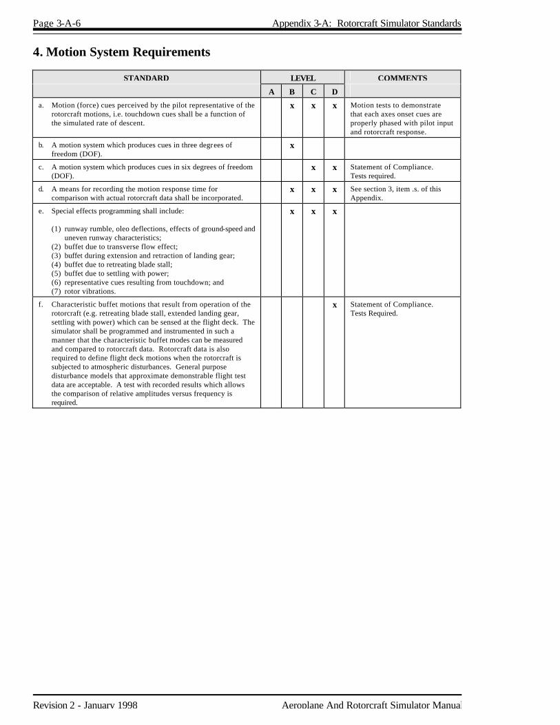
Page 3-A-6 Appendix 3-A: Rotorcraft Simulator Standards
Revision 2 - January 1998 Aeroplane And Rotorcraft Simulator Manual
4. Motion System Requirements
STANDARD LEVEL COMMENTS
A B C D
a. Motion (force) cues perceived by the pilot representative of the rotorcraft motions, i.e. touchdown cues shall be a function of the simulated rate of descent.
x x x Motion tests to demonstrate that each axes onset cues are properly phased with pilot input and rotorcraft response.
b. A motion system which produces cues in three degrees of freedom (DOF).
x
c. A motion system which produces cues in six degrees of freedom (DOF).
x x Statement of Compliance. Tests required.
d. A means for recording the motion response time for comparison with actual rotorcraft data shall be incorporated.
x x x See section 3, item .s. of this Appendix.
e. Special effects programming shall include: (1) runway rumble, oleo deflections, effects of ground-speed and
uneven runway characteristics; (2) buffet due to transverse flow effect; (3) buffet during extension and retraction of landing gear; (4) buffet due to retreating blade stall; (5) buffet due to settling with power; (6) representative cues resulting from touchdown; and (7) rotor vibrations.
x x x
f. Characteristic buffet motions that result from operation of the rotorcraft (e.g. retreating blade stall, extended landing gear, settling with power) which can be sensed at the flight deck. The simulator shall be programmed and instrumented in such a manner that the characteristic buffet modes can be measured and compared to rotorcraft data. Rotorcraft data is also required to define flight deck motions when the rotorcraft is subjected to atmospheric disturbances. General purpose disturbance models that approximate demonstrable flight test data are acceptable. A test with recorded results which allows the comparison of relative amplitudes versus frequency is required.
x Statement of Compliance. Tests Required.
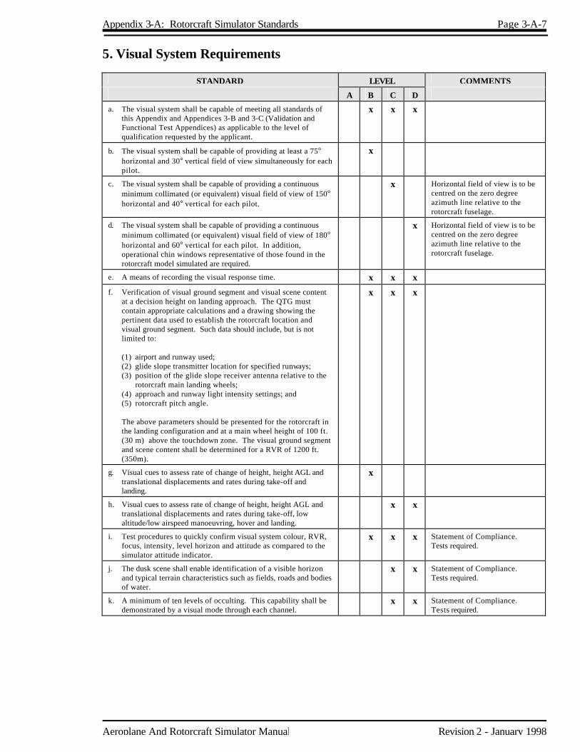
Appendix 3-A: Rotorcraft Simulator Standards Page 3-A-7
Aeroplane And Rotorcraft Simulator Manual Revision 2 - January 1998
5. Visual System Requirements
STANDARD LEVEL COMMENTS
A B C D
a. The visual system shall be capable of meeting all standards of this Appendix and Appendices 3-B and 3-C (Validation and Functional Test Appendices) as applicable to the level of qualification requested by the applicant.
x x x
b. The visual system shall be capable of providing at least a 75° horizontal and 30° vertical field of view simultaneously for each pilot.
x
c. The visual system shall be capable of providing a continuous minimum collimated (or equivalent) visual field of view of 150° horizontal and 40° vertical for each pilot.
x Horizontal field of view is to be centred on the zero degree azimuth line relative to the rotorcraft fuselage.
d. The visual system shall be capable of providing a continuous minimum collimated (or equivalent) visual field of view of 180° horizontal and 60° vertical for each pilot. In addition, operational chin windows representative of those found in the rotorcraft model simulated are required.
x Horizontal field of view is to be centred on the zero degree azimuth line relative to the rotorcraft fuselage.
e. A means of recording the visual response time. x x x
f. Verification of visual ground segment and visual scene content at a decision height on landing approach. The QTG must contain appropriate calculations and a drawing showing the pertinent data used to establish the rotorcraft location and visual ground segment. Such data should include, but is not limited to:
(1) airport and runway used; (2) glide slope transmitter location for specified runways; (3) position of the glide slope receiver antenna relative to the
rotorcraft main landing wheels; (4) approach and runway light intensity settings; and (5) rotorcraft pitch angle. The above parameters should be presented for the rotorcraft in
the landing configuration and at a main wheel height of 100 ft. (30 m) above the touchdown zone. The visual ground segment and scene content shall be determined for a RVR of 1200 ft. (350m).
x x x
g. Visual cues to assess rate of change of height, height AGL and translational displacements and rates during take-off and landing.
x
h. Visual cues to assess rate of change of height, height AGL and translational displacements and rates during take-off, low altitude/low airspeed manoeuvring, hover and landing.
x x
i. Test procedures to quickly confirm visual system colour, RVR, focus, intensity, level horizon and attitude as compared to the simulator attitude indicator.
x x x Statement of Compliance. Tests required.
j. The dusk scene shall enable identification of a visible horizon and typical terrain characteristics such as fields, roads and bodies of water.
x x Statement of Compliance. Tests required.
k. A minimum of ten levels of occulting. This capability shall be demonstrated by a visual mode through each channel.
x x Statement of Compliance. Tests required.

Page 3-A-8 Appendix 3-A: Rotorcraft Simulator Standards
Revision 2 - January 1998 Aeroplane And Rotorcraft Simulator Manual
STANDARD LEVEL COMMENTS
A B C D
l. Daylight, dusk and night visual scenes with sufficient scene content to recognize airport, terrain and major landmarks around the airport and to successfully accomplish a visual landing. The daylight visual scene shall be part of a total daylight cockpit environment which at least represents the amount of light in the cockpit on an overcast day. Daylight visual system is defined as a visual system capable of producing, as a minimum, full colour presentations, scene content comparable in detail to that produced by 4,000 edges or 1,000 surfaces for daylight and 4,000 light points for night and dusk scenes, 6-foot lamberts of light measured at the pilot's eye position (highlight brightness), 3 arc minutes resolution for the field of view at the pilot's eye and a display which is free of apparent quantization and other distracting visual effects while the simulator is in motion.
The simulator cockpit ambient lighting shall be dynamically
consistent with the visual scene displayed. For daylight scenes, such ambient lighting shall neither "washout" the displayed visual scene nor fall below 5-foot lamberts of light as reflected from an approach plate at knee height at the pilot's station. All brightness and resolution requirements shall be validated by an objective test and will be re-tested at least yearly by the MSP. Testing may be accomplished more frequently if there are indications that the performance is degrading on an accelerated basis. Compliance of the brightness capability may be demonstrated with a test pattern of white light using a spot photometer.
(1) Contrast Ratio — A raster drawn test pattern filling the
entire visual scene (three or more channels) shall consist of a matrix of black and white squares no larger than 10° and no smaller than 5° per square with a white square in the centre of each channel. Measurement shall be made on the centre bright square for each channel using a 1° spot photometer. This value shall have a minimum brightness of 2-foot lamberts. Measure any adjacent dark squares. The contrast ratio is the bright square value divided by the dark square value.
Minimum test contrast ratio result is 5:1. (2) Highlight brightness — Maintaining the full test pattern
described above, superimpose a highlight area on the centre white square of each channel and measure the brightness using the 1° spot photometer. Light points are not acceptable. Use of calligraphic capabilities to enhance raster brightness is acceptable.
(3) Surface resolution will be demonstrated by a test pattern of
objects shown to occupy a visual angle of 3 arc minutes in the visual scene from the pilot's eyepoint. This shall be confirmed by calculations in the Statement of Compliance.
(4) Lightpoint size. Not greater than 6 arc minutes measured in
a test pattern consisting of a single row of light points reduced in length until modulation is just discernible, a row of 40 lights will form a 4° angle or less.
(5) Lightpoint contrast ratio. Not less than 25:1 when a square
of at least 1° filled with lightpoints (i.e. lightpoint modulation is just discernible) is compared to the adjacent background.
x Note: Cockpit ambient light
levels shall be maintained at Level D requirements.

Aeroplane And Rotorcraft Simulator Manual Revision 2 - January 1998
Appendix 3-B Rotorcraft Simulator Validation Tests 1. Discussion Simulator performance and system operation shall be objectively evaluated by comparing each performance and stability and control test conducted in the simulator to rotorcraft data unless specifically noted otherwise. To facilitate the validation of the simulator, a multi-channel recorder, line printer or other appropriate device, acceptable to the MSP, shall be used to record each validation test. The results of these recordings shall then be compared to the rotorcraft source data. The QTG provided by the operator shall describe clearly and distinctly how the simulator will be set up and operated for each test. Use of a drive program designed to automatically accomplish the tests is encouraged but procedures shall be included to positively determine that the driver is doing nothing more than accurately flying the simulator. It is not the intent and it is not acceptable to TC to test each simulator subsystem independently. Overall integrated testing of the simulator must be accomplished to assure that the total simulator system meets the prescribed standards. A manual test procedure with explicit and detailed steps for completion of each test must also be provided. The tests and tolerances contained in this Appendix shall be included in the sponsor's QTG. Levels B, C and D simulators must be compared to flight test data except as otherwise specified. For rotorcraft certified prior to June 1980, the sponsor may, after reasonable attempts to obtain suitable flight test data have failed, indicate in the QTG where flight test data is unavailable or unsuitable for a specific test. For such a test, alternative data shall be submitted to the MSP for approval. Submissions for approval of data other than flight test shall include an explanation of validity with respect to available flight test information. The Table of Validation Tests of this Appendix generally indicates the test results required. Unless otherwise specified, simulator tests shall represent rotorcraft performance and handling qualities at normal operating weights and centres of gravity (CG). If a test is supported by rotorcraft data at one extreme weight or CG, another test supported by rotorcraft data at mid-conditions or as close as possible to the other extreme shall be included. Where multiple gross weights and/or CG are specified, these data shall be presented for conditions as close as possible to the operational extremes of the flight envelope. Certain tests which are relevant only at one extreme CG or weight condition need not be repeated at the other extreme. Tests of handling qualities must include validation of stability and control augmentation devices. Simulators for augmented rotorcraft will be validated both in the non-augmented configuration (or failure state with the maximum permitted degradation in handling qualities) and the augmented configuration. Where various levels of handling qualities result from failure states, validation of the effect of the failure is necessary. For those performance and static handling qualities tests where the primary concern, in the non-augmented configuration, is control position, non-augmented data are not required if the design of the system precludes any effect on control position. In those instances where the non-augmented rotorcraft response is divergent and non-repeatable, it may not be feasible to meet the specified tolerances. Alternative requirements for testing will be mutually agreed to between the operator and the MSP on a case-by-case basis. In the case of rotorcraft simulators approved in accordance with criteria in effect prior to the issue of this manual revision, the tolerances of this Appendix may be used in subsequent recurrent evaluation for any given test provided the operator has submitted a proposed QTG revision to the MSP and has received approval. These validation tests are meant to be identical to the latest FAA requirements. In this case, they reflect

Page 3-B-2 Appendix 3-B: Rotorcraft Simulator Validation Tests
Revision 2 - January 1998 Aeroplane And Rotorcraft Simulator Manual
FAA Advisory Circular 120-63. 2. Test Requirements The ground and flight tests which shall be evaluated, as appropriate to the type of rotorcraft, are listed under Validation Tests in this Appendix. Computer generated simulator test results shall be provided for each test. The results shall be produced on a multi-channel recorder, line printer or other appropriate recording device acceptable to the MSP. Time histories are required unless otherwise indicated in the Table of Validation Tests. Flight test data which exhibits rapid variations of the measured parameters may require engineering judgement when making assessments of simulator validity. Such judgement must not be limited to a single parameter. All relevant parameters related to a given manoeuvre or flight condition must be provided to allow overall interpretation. When it is difficult or impossible to match simulator to rotorcraft data throughout a time history, differences must be justified by providing a comparison of other related variables for the condition being assessed. Parameters, Tolerances and Flight Conditions The Validation Tests section of this Appendix describes the parameters, tolerances and flight conditions for simulator validation. These tolerances are intended to account for the inexact modelling and reference data. When two tolerance values are given for a parameter, the percentage tolerance applies to the recorded value of that parameter. The less restrictive of the two tolerance values may be used unless otherwise indicated. In those cases where a tolerance is expressed only as a percentage, the tolerance applies to the maximum value of that parameter within its normal operating range as measured from the neutral or zero position unless otherwise indicated. If a flight condition or operating condition is shown which does not apply to the qualification level sought, then it should be disregarded. Simulator results must be labelled using the tolerances and units given. Flight Conditions Verification When comparing the parameters listed to those of the rotorcraft, sufficient data must also be provided to verify the correct flight conditions. For example, to show that control force is within ±0.5 lb (0.223 daN) in a static stability test, data to show the correct airspeed, power, thrust or torque, rotorcraft configuration, altitude and other appropriate datum identification parameters shall also be given. If comparing short period dynamics, normal acceleration may be used to establish a match to the rotorcraft, but airspeed, altitude, control input, rotorcraft configuration and other appropriate data shall also be given. All airspeed values shall be clearly annotated as to indicated, calibrated, etc., and like values must be used for comparison. Alternate Method for Dynamic Handling Qualities Tests TC is open to alternative means for dealing with dynamic handling qualities tests. One method that has been suggested is frequency response testing. Such alternatives must be justified and appropriate to the application. Each case must be considered on its own merit on an ad hoc basis. Should TC find that alternative methods do not result in satisfactory simulator performance, more conventionally accepted methods must be used.

Appendix 3-B: Rotorcraft Simulator Validation Tests Page 3-B-3
Aeroplane And Rotorcraft Simulator Manual Revision 2 - January 1998
3. Table of Validation Tests
Test Tolerance Flt Condition Requirement Comments
A B C D
1. PERFORMANCE
A. Engine Assessment
1. Start Operations
(a)Engine Start and Acceleration (transient)
Light Off Time - ±10% or ±1 sec Torque - ±5% Rotor Speed - ±3% Fuel Flow - ±10% Gas Generator Speed - ±5% Power Turbine Speed - ±5% Turbine Gas Temp. - ±30°C
Ground Rotor Brake Used/Not Used
x x x Time histories of each engine from initiation of start sequence to steady state idle and from steady state idle to operating RPM.
(b)Steady State Idle and Operating RPM Conditions
Torque - ±3% Rotor Speed - ±1.5% Fuel Flow - ±5% Gas Generator Speed - ±2% Power Turbine Speed - ±2% Turbine Gas Temp. - ±20°C
Ground x x x Present data for both steady state idle and operating RPM conditions. May be a snapshot test.
2. Power Turbine Speed Trim
±10% of total change of power turbine speed
Ground x x x Time history of engine response to trim system actuation (both directions).
3. Engine and Rotor Speed Governing
Torque - ±5% Rotor Speed - ±1.5%
Climb/Descent x x x Collective step inputs. Can be conducted concurrently with climb and descent performance tests.
B. Ground Operations
1. Minimum Radius Turn ±3 feet (0.9m) or 20% of Rotorcraft Turn Radius
Ground x x x If differential braking is used, brake force must be set at the rotorcraft flight test value.
2. Rate of Turn Versus Pedal Deflection or Nosewheel Angle
±10% or ±2°/sec. Turn Rate
Ground x x x
3. Taxi Pitch Attitude - ±1.5° Torque - ±3% Longitudinal Control Position - ±5% Lateral Control Position - ±5% Directional Control Position - ±5% Collective Control Position - ±5%
Ground x x x Control position and pitch attitude during ground taxi for a specific ground speed, wind speed and direction, and density altitude.
4. Brake Effectiveness ±10% of time and distance
Ground x x x

Page 3-B-4 Appendix 3-B: Rotorcraft Simulator Validation Tests
Revision 2 - January 1998 Aeroplane And Rotorcraft Simulator Manual
Test Tolerance Flt Condition Requirement Comments
A B C D
C. Take-off
1. All Engines Airspeed - ±3 kt Altitude - ±20 feet (6.1 m) Torque - ±3% Rotor Speed - ±1.5% Vertical Velocity - ±100 fpm (0.50 m/sec) or 10% Pitch Attit ude - ±1.5° Bank Attitude - ±2° Heading ±2° Longitudinal Control Position - ±10% Lateral Control Position - ±10% Directional Control Position - ±10% Collective Control Position - ±10%
Ground/Take-off and Initial Segment of Climb
x x x Time history of take-off flight path as appropriate to rotorcraft model simulated (running take-off for Level B, take-off from a hover for Levels C and D). For Level B, criteria apply only to those segments at airspeeds above effective translational lift. Record data to at least 200 feet (61m) AGL.
2. One Engine Inoperative
See 1.C.1. above for tolerances and flight conditions
x x x Time history of take-off flight path as appropriate to rotorcraft model simulated. Record data to at least 200 feet (61m) AGL.
D. Hover Performance Torque - ±3% Pitch Attitude - ±1.5° Bank Attitude - ±1.5° Longitudinal Control Position - ±5% Lateral Control Position - ±5% Directional Control Position - ±5% Collective Control Position - ±5%
In Ground Effect (IGE) Out of Ground Effect (OGE)
x x Light/heavy/gross weights. May be a snapshot test.
E. Vertical Climb Performance
Vertical Velocity - ±100 fpm (0.50 m/sec) or 10% Directional Control Position - ±5% Collective Control Position - ±5%
From OGE Hover
x x Light/heavy/gross weights. May be a snapshot test.
F. Level Flight Performance and Trimmed Flight Control Positions
Torque - ±3% Pitch Attitude - ±1.5° Sideslip Angle - ±2° Longitudinal Control Position - ±5% Lateral Control Position - ±5% Directional Control Position - ±5% Collective Control Position - ±5%
Cruise Augmentation On/Off
x x x Two gross weight/CG combinations. Vary trim speeds throughout airspeed envelope. May be a snapshot test.

Appendix 3-B: Rotorcraft Simulator Validation Tests Page 3-B-5
Aeroplane And Rotorcraft Simulator Manual Revision 2 - January 1998
Test Tolerance Flt Condition Requirement Comments
A B C D
G. Climb Performance and Trimmed Flight Control Positions
Vertical Velocity - ±100 fpm (0.50 m/sec) or 10% Pitch Attitude - ±1.5° Sideslip Angle - ±2° Longitudinal Control Position - ±5% Lateral Control Position - ±5% Directional Control Position - ±5% Collective Control Position - ±5%
All engines operating One engine inoperative Augmentation On/off
x x x Two gross weight/CG combinations. Data presented at normal climb power conditions. May be a snapshot test.
H. Descent x x x
1. Descent Performance and Trimmed Flight Control Positions
Torque - ±3% Pitch Attitude - ±1.5% Sideslip Angle - ±2% Longitudinal Control Position - ±5% Lateral Control Position - ±5% Directional Control Position - ±5% Collective Control Position - ±5%
At or near 1,000 fpm Rate of Descent (RoD) at normal approach speed Augmentation On/Off
Two gross weight/CG combinations. May be a snapshot test.
2. Autorotation Performance and Trimmed Flight Control Positions
Vertical Velocity - ±100 fpm (0.50 m/sec) or 10% Rotor Speed - ±1.5% Pitch Attitude - ±1.5° Sideslip Angle - ±2° Longitudinal Control Position ±5% Lateral Control Position ±5% Directional Control Position ±5%
Steady descents Augmentation On/Off
x x x Two gross weights. At normal operating RPM. Rotor speed tolerance only applies if collective control position is full down. Speed sweep from approximately 50 Knots to at least maximum glide distance airspeed. May be a snapshot test.
I. Autorotational Entry Rotor speed ±3% Pitch Attitude ±2° Roll Attitude ±3° Yaw Attitude ±5° Airspeed - ±5 kt Vertical Velocity - ±200 fpm (1.00 m/sec) or 10%
Cruise or Climb x x Time history of vehicle response to a rapid throttle reduction to idle. If cruise, data should be presented for the maximum range airspeed. If climb, data should be presented for the maximum rate of climb airspeed at or near maximum continuous power.
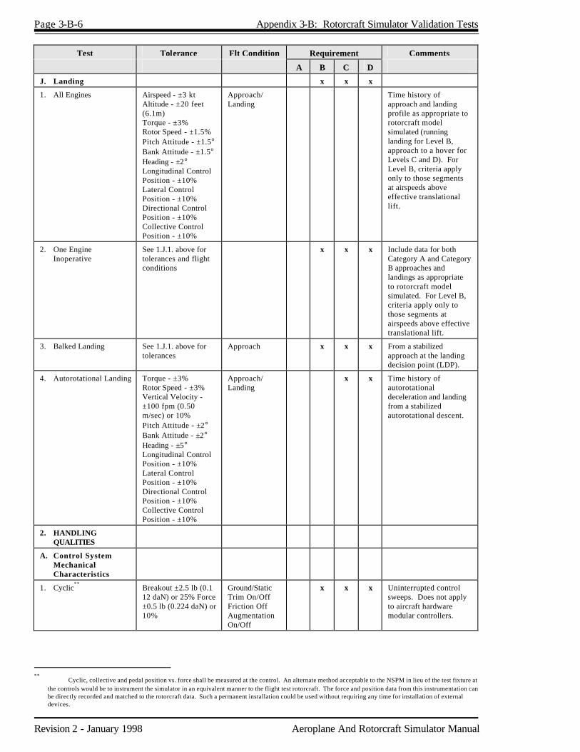
Page 3-B-6 Appendix 3-B: Rotorcraft Simulator Validation Tests
Revision 2 - January 1998 Aeroplane And Rotorcraft Simulator Manual
Test Tolerance Flt Condition Requirement Comments
A B C D
J. Landing x x x
1. All Engines Airspeed - ±3 kt Altitude - ±20 feet (6.1m) Torque - ±3% Rotor Speed - ±1.5% Pitch Attitude - ±1.5° Bank Attitude - ±1.5° Heading - ±2° Longitudinal Control Position - ±10% Lateral Control Position - ±10% Directional Control Position - ±10% Collective Control Position - ±10%
Approach/ Landing
Time history of approach and landing profile as appropriate to rotorcraft model simulated (running landing for Level B, approach to a hover for Levels C and D). For Level B, criteria apply only to those segments at airspeeds above effective translational lift.
2. One Engine Inoperative
See 1.J.1. above for tolerances and flight conditions
x x x Include data for both Category A and Category B approaches and landings as appropriate to rotorcraft model simulated. For Level B, criteria apply only to those segments at airspeeds above effective translational lift.
3. Balked Landing See 1.J.1. above for tolerances
Approach x x x From a stabilized approach at the landing decision point (LDP).
4. Autorotational Landing Torque - ±3% Rotor Speed - ±3% Vertical Velocity - ±100 fpm (0.50 m/sec) or 10% Pitch Attitude - ±2° Bank Attitude - ±2° Heading - ±5° Longitudinal Control Position - ±10% Lateral Control Position - ±10% Directional Control Position - ±10% Collective Control Position - ±10%
Approach/ Landing
x x Time history of autorotational deceleration and landing from a stabilized autorotational descent.
2. HANDLING QUALITIES
A. Control System Mechanical Characteristics
1. Cyclic**
Breakout ±2.5 lb (0.1 12 daN) or 25% Force ±0.5 lb (0.224 daN) or 10%
Ground/Static Trim On/Off Friction Off Augmentation On/Off
x x x Uninterrupted control sweeps. Does not apply to aircraft hardware modular controllers.
**
Cyclic, collective and pedal position vs. force shall be measured at the control. An alternate method acceptable to the NSPM in lieu of the test fixture at the controls would be to instrument the simulator in an equivalent manner to the flight test rotorcraft. The force and position data from this instrumentation can be directly recorded and matched to the rotorcraft data. Such a permanent installation could be used without requiring any time for installation of external devices.
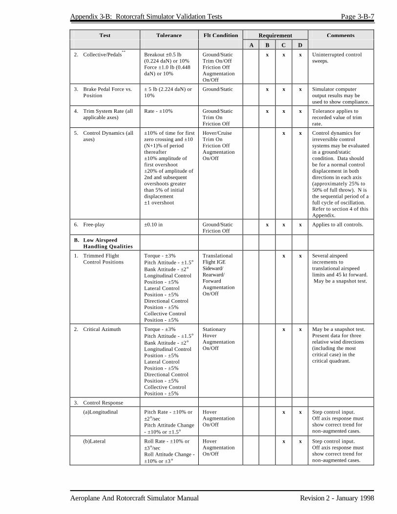
Appendix 3-B: Rotorcraft Simulator Validation Tests Page 3-B-7
Aeroplane And Rotorcraft Simulator Manual Revision 2 - January 1998
Test Tolerance Flt Condition Requirement Comments
A B C D
2. Collective/Pedals**
Breakout ±0.5 lb (0.224 daN) or 10% Force ±1.0 lb (0.448 daN) or 10%
Ground/Static Trim On/Off Friction Off Augmentation On/Off
x x x Uninterrupted control sweeps.
3. Brake Pedal Force vs. Position
± 5 lb (2.224 daN) or 10%
Ground/Static x x x Simulator computer output results may be used to show compliance.
4. Trim System Rate (all applicable axes)
Rate - ±10% Ground/Static Trim On Friction Off
x x x Tolerance applies to recorded value of trim rate.
5. Control Dynamics (all axes)
±10% of time for first zero crossing and ±10 (N+1)% of period thereafter ±10% amplitude of first overshoot ±20% of amplitude of 2nd and subsequent overshoots greater than 5% of initial displacement ±1 overshoot
Hover/Cruise Trim On Friction Off Augmentation On/Off
x x Control dynamics for irreversible control systems may be evaluated in a ground/static condition. Data should be for a normal control displacement in both directions in each axis (approximately 25% to 50% of full throw). N is the sequential period of a full cycle of oscillation. Refer to section 4 of this Appendix.
6. Free-play ±0.10 in Ground/Static Friction Off
x x x Applies to all controls.
B. Low Airspeed Handling Qualities
1. Trimmed Flight Control Positions
Torque - ±3% Pitch Attitude - ±1.5° Bank Attitude - ±2° Longitudinal Control Position - ±5% Lateral Control Position - ±5% Directional Control Position - ±5% Collective Control Position - ±5%
Translational Flight IGE Sideward/ Rearward/ Forward Augmentation On/Off
x x Several airspeed increments to translational airspeed limits and 45 kt forward. May be a snapshot test.
2. Critical Azimuth Torque - ±3% Pitch Attitude - ±1.5° Bank Attitude - ±2° Longitudinal Control Position - ±5% Lateral Control Position - ±5% Directional Control Position - ±5% Collective Control Position - ±5%
Stationary Hover Augmentation On/Off
x x May be a snapshot test. Present data for three relative wind directions (including the most critical case) in the critical quadrant.
3. Control Response
(a)Longitudinal Pitch Rate - ±10% or ±2°/sec Pitch Attitude Change - ±10% or ±1.5°
Hover Augmentation On/Off
x x Step control input. Off axis response must show correct trend for non-augmented cases.
(b)Lateral Roll Rate - ±10% or ±3°/sec Roll Attitude Change - ±10% or ±3°
Hover Augmentation On/Off
x x Step control input. Off axis response must show correct trend for non-augmented cases.

Page 3-B-8 Appendix 3-B: Rotorcraft Simulator Validation Tests
Revision 2 - January 1998 Aeroplane And Rotorcraft Simulator Manual
Test Tolerance Flt Condition Requirement Comments
A B C D
(c)Directional Yaw Rate - ±10% or ±2°/sec Heading Change - ±10% or ±2°
Hover Augmentation On/Off
x x Step control input. Off axis response must show correct trend for non-augmented cases.
(d)Vertical Normal Acceleration - ±0.1g
Hover x x Step control input. Off axis response must show correct t rend for non-augmented cases.
C. Longitudinal Handling Qualities
Two cruise airspeeds to include minimum power required speed.
1. Control Response Pitch Rate - ±10% or ±2°/sec Pitch Attitude Change - ±10% or ±1.5°
Cruise Augmentation On/Off
x x x Step control input. Off axis response must show correct trend for non-augmented cases.
2. Static Stability Longitudinal Control Position - ±10% of change from trim or ±0.25 in (6.3 mm) or Longitudinal Control Force - ±0.5 lb (0.223 daN) or ±10%
Cruise or Climb Autorotation Augmentation On/Off
x x x Minimum of two speeds on each side of the trim speed. May be a snapshot test.
3. Dynamic Stability
(a)Long Term Response
±10% of Calculated Period ±10% of Time to ½ or Double Amplitude or ±.02 of Damping Ratio
Cruise Augmentation On/Off
x x x Test should include three full cycles (6 overshoots after input completed) or that sufficient to determine time to ½ or double amplitude, whichever is less. For non-periodic response the time history should be matched.
(b)Short Term Response
±1.5° Pitch or ±2°/sec Pitch Rate ±0.1g Normal Acceleration
Cruise or Climb Augmentation On/Off
x x x Two airspeeds.
4. Manoeuvring Stability Longitudinal Control Position - ±10% of change from trim or ±0.25 in (6.3 mm) or Longitudinal Control Force - ±0.5 lb (0.223 daN) or ±10%
Cruise or Climb Augmentation On/Off
x x x Force may be a cross plot for irreversible systems. Two airspeeds. May be a snapshot test. Approximately 30° and 45° bank attitude data should be presented.
5. Landing Gear Operating Time
±1 sec
Take-off (retraction) Approach (extension)
x x x
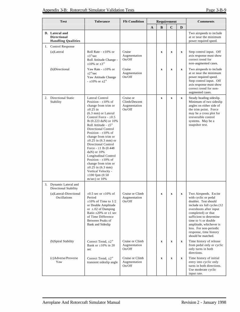
Appendix 3-B: Rotorcraft Simulator Validation Tests Page 3-B-9
Aeroplane And Rotorcraft Simulator Manual Revision 2 - January 1998
Test Tolerance Flt Condition Requirement Comments
A B C D
D. Lateral and Directional Handling Qualities
Two airspeeds to include at or near the minimum power required speed.
1. Control Response
(a)Lateral Roll Rate - ±10% or ±3°/sec Roll Attitude Change - ±10% or ±3°
Cruise Augmentation On/Off
x x x Step control input. Off axis response must show correct trend for non-augmented cases.
(b)Directional Yaw Rate - ±10% or ±2°/sec Yaw Attitude Change - ±10% or ±2°
Cruise Augmentation On/Off
x x x Two airspeeds to include at or near the minimum power required speed. Step control input. Off axis response must show correct trend for non-augmented cases.
2. Directional Static Stability
Lateral Control Position - ±10% of change from trim or ±0.25 in (6.3 mm) or Lateral Control Force - ±0.5 lb (0.223 daN) or 10% Roll Attitude - ±5° Directional Control Position - ±10% of change from trim or ±0.25 in (6.3 mm) or Directional Control Force - ±1 lb (0.448 daN) or 10% Longitudinal Control Position - ±10% of change from trim or ±0.25 in (6.3 mm) Vertical Velocity - ±100 fpm (0.50 m/sec) or 10%
Cruise or Climb/Descent Augmentation On/Off
x x x Steady heading sideslip. Minimum of two sideslip angles on either side of the trim point. Force may be a cross plot for irreversible control systems. May be a snapshot test.
3. Dynamic Lateral and Directional Stability
(a)Lateral-Directional Oscillations
±0.5 sec or ±10% of Period ±10% of Time to 1/2 or Double Amplitude or ±.02 of Damping Ratio ±20% or ±1 sec of Time Difference Between Peaks of Bank and Sideslip
Cruise or Climb Augmentation On/Off
x x x Two Airspeeds. Excite with cyclic or pedal doublet. Test should include six full cycles (12 overshoots after input completed) or that sufficient to determine time to ½ or double amplitude, whichever is less. For non-periodic response, time history should be matched.
(b)Spiral Stability Correct Trend, ±2° Bank or ±10% in 20 sec
Cruise or Climb Augmentation On/Off
x x x Time history of release from pedal only or cyclic only turns in both directions.
(c)Adverse/Proverse Yaw
Correct Trend, ±2° transient sideslip angle
Cruise or Climb Augmentation On/Off
x x x Time history of initial entry into cyclic only turns in both directions. Use moderate cyclic input rate.

Page 3-B-10 Appendix 3-B: Rotorcraft Simulator Validation Tests
Revision 2 - January 1998 Aeroplane And Rotorcraft Simulator Manual
Test Tolerance Flt Condition Requirement Comments
A B C D
3. MOTION SYSTEM**
A. Motion Envelope
1. Pitch N/A
(a)Displacement ±TBD° ±25°
x x
x
(b)Velocity ±TBD°/sec ±20°/sec
x x
x
(c)Acceleration ±TBD°/sec
2
±100°/sec2
x x
x
2. Roll
(a)Displacement ±TBD° ±25°
x x
x
(b)Velocity ±TBD°/sec ±20°/sec
x x
x
(c)Acceleration ±TBD°/sec
2
±100°/sec2
x x
x
3. Yaw N/A
(a)Displacement ±25° x x
(b)Velocity ±20°/sec x x
(c)Acceleration ±100°/sec
2
x x
4. Vertical
(a)Displacement ±TBD in ±34 in
x x
x
(b)Velocity ±TBD in ±24 in/sec
x x
x
(c)Acceleration ±TBD g ±0.8g
x x
x
5. Lateral N/A
(a)Displacement ±45 in x x
(b)Velocity ±28 in/sec x x
(c)Acceleration ±0.6g x x
6. Longitudinal
(a)Displacement ±34 in x x
(b)Velocity ±28 in/sec x x
(c)Acceleration ±0.6g x x
7. Initial Rotational Acceleration Ratio, All Axes
TBD°/sec
2/sec
300°/sec2/sec
x
x
x
**
It is assumed that the three degrees of freedom (DOF) for a Level B simulator are pitch, roll and vertical. If the installed system has more than three DOF, but less than six, or three DOF different from pitch, roll, and vertical, the motion performance will have to be established on a per case basis. A level B simulator with a six-DOF system shall comply with Level C and Level D motion performance. If none of the descriptions apply, the applicant shall provide the NSPM with a system description and performance analysis.

Appendix 3-B: Rotorcraft Simulator Validation Tests Page 3-B-11
Aeroplane And Rotorcraft Simulator Manual Revision 2 - January 1998
Test Tolerance Flt Condition Requirement Comments
A B C D
8. Initial Linear Acceleration Rate
(a)Vertical ±TBD g/sec ±6 g/sec
x x
x
(b)Lateral ±3 g/sec x x
(c)Longitudinal ±3 g/sec
x
x
B. Frequency Response Amplitude
N/A
Band, Hz 0.1 to 0.5
0.51 to 1.0 1.1 to 2.0 2.1 to 5.0
Phase, deg -15 to -20 -15 to -20 -20 to -40
-40 to -100
Ratio, dB ±2 ±2 ±4 ±4
x x x
C. Leg Balance 1.5° x x x The phase shift between a datum jack and any other jack shall be measured using a heave (vertical) signal of 0.5 Hz at ±0.25g
D. Turn Around 0.05g N/A x x x The motion base shall be driven sinusoidally in heave through a displacement of 6 in (150 mm) peak to peak at a frequency of 0.5 Hz. Deviation from the desired sinusoidal acceleration shall be measured.
E. Motion Cue Repeatability
x x x See Section 4 of this Appendix.
4. VISUAL SYSTEM Note: Refer to Appendix 3-C for additional visual tests.
A. Visual Ground Segment (VGS)
±20% of calculated VGS. Threshold lights must be visible if they are in the visual segment (see example under "Comments").
Static at 100 ft (30.5m) wheel height above touchdown zone on glideslope RVR = 1200 ft (350m)
x x x The QTG should indicate the source of data, i.e. ILS G/S antenna location, pilot eye reference point, cockpit cut -off angle, etc., used to make visual scene ground segment content calculations. Tolerance Example: If the calculated VGS for the rotorcraft is 840 ft, the 20% tolerance of 168 ft may be applied at the near or far end of the simulator VGS or may be split between both as long as the total of 168 ft is not exceeded.
B. Visual System Colour
Demonstration Model x x
C. Visual RVR Calibration
Demonstration Model x x
D. Visual Display Focus and Intensity
Demonstration Model x x
E. Visual Attitude vs. Simulator Attitude Indicator (Pitch and Roll of Horizon)
Demonstration Model x x

Page 3-B-12 Appendix 3-B: Rotorcraft Simulator Validation Tests
Revision 2 - January 1998 Aeroplane And Rotorcraft Simulator Manual
Test Tolerance Flt Condition Requirement Comments
A B C D
F. Demonstrate 10 Levels of Occulting Through Each Channel of System
Demonstration Model x x
5. SIMULATOR SYSTEMS
A. Visual, Motion and Cockpit Instrument Systems Response
1. Visual, Motion and Instrument System Response to an abrupt pilot controller input, compared to rotorcraft response for a similar input
100 milliseconds or less after rotorcraft response 150 milliseconds or less after rotorcraft response
Climb, Cruise, Descent, Hover Take-off, Climb, Descent
x
x x One test is required in each axis (Pitch, Roll and Yaw) for each of the 4 conditions (3 conditions, Level B) compared to rotorcraft data for a similar input. (Total 12 tests) (Total 9 tests, Level B)
OR
2. Transport Delay 100 milliseconds or less after control movement 150 milliseconds or less after control movement
Pitch, Roll, Yaw Pitch, Roll, Yaw
x
x x One test is required in each axis (total 3 tests). See Appendix 3-A, Section 3, paragraph t.
B. Sound
1. Realistic amplitude and frequency of cockpit noises and sounds, including transmission, rotor and airframe sounds
x Test results must show a comparison of the amplitude and frequency content of the sounds that originate from the rotorcraft or rotorcraft systems. Sound data should be presented in one-third octave band or continuous frequency spectrum.
C. Diagnosti c Testing
1. A means for quickly and effectively testing simulator programming and hardware. This could include an automated system which could be used for conducting at least a portion of the tests in the QTG
x x
2. Self testing of simulator hardware and programming.
x
3. Diagnostic analysis printout of simulator malfunctions sufficient to determine compliance with the SCIG
x
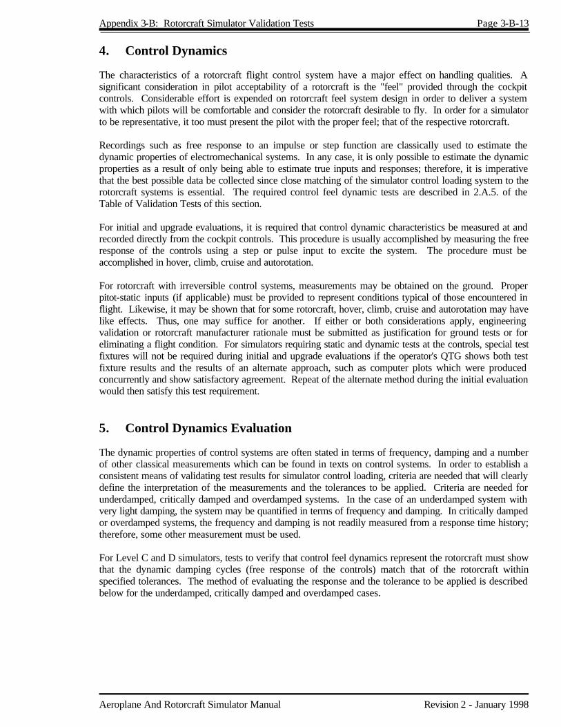
Appendix 3-B: Rotorcraft Simulator Validation Tests Page 3-B-13
Aeroplane And Rotorcraft Simulator Manual Revision 2 - January 1998
4. Control Dynamics The characteristics of a rotorcraft flight control system have a major effect on handling qualities. A significant consideration in pilot acceptability of a rotorcraft is the "feel" provided through the cockpit controls. Considerable effort is expended on rotorcraft feel system design in order to deliver a system with which pilots will be comfortable and consider the rotorcraft desirable to fly. In order for a simulator to be representative, it too must present the pilot with the proper feel; that of the respective rotorcraft. Recordings such as free response to an impulse or step function are classically used to estimate the dynamic properties of electromechanical systems. In any case, it is only possible to estimate the dynamic properties as a result of only being able to estimate true inputs and responses; therefore, it is imperative that the best possible data be collected since close matching of the simulator control loading system to the rotorcraft systems is essential. The required control feel dynamic tests are described in 2.A.5. of the Table of Validation Tests of this section. For initial and upgrade evaluations, it is required that control dynamic characteristics be measured at and recorded directly from the cockpit controls. This procedure is usually accomplished by measuring the free response of the controls using a step or pulse input to excite the system. The procedure must be accomplished in hover, climb, cruise and autorotation. For rotorcraft with irreversible control systems, measurements may be obtained on the ground. Proper pitot-static inputs (if applicable) must be provided to represent conditions typical of those encountered in flight. Likewise, it may be shown that for some rotorcraft, hover, climb, cruise and autorotation may have like effects. Thus, one may suffice for another. If either or both considerations apply, engineering validation or rotorcraft manufacturer rationale must be submitted as justification for ground tests or for eliminating a flight condition. For simulators requiring static and dynamic tests at the controls, special test fixtures will not be required during initial and upgrade evaluations if the operator's QTG shows both test fixture results and the results of an alternate approach, such as computer plots which were produced concurrently and show satisfactory agreement. Repeat of the alternate method during the initial evaluation would then satisfy this test requirement. 5. Control Dynamics Evaluation The dynamic properties of control systems are often stated in terms of frequency, damping and a number of other classical measurements which can be found in texts on control systems. In order to establish a consistent means of validating test results for simulator control loading, criteria are needed that will clearly define the interpretation of the measurements and the tolerances to be applied. Criteria are needed for underdamped, critically damped and overdamped systems. In the case of an underdamped system with very light damping, the system may be quantified in terms of frequency and damping. In critically damped or overdamped systems, the frequency and damping is not readily measured from a response time history; therefore, some other measurement must be used. For Level C and D simulators, tests to verify that control feel dynamics represent the rotorcraft must show that the dynamic damping cycles (free response of the controls) match that of the rotorcraft within specified tolerances. The method of evaluating the response and the tolerance to be applied is described below for the underdamped, critically damped and overdamped cases.

Page 3-B-14 Appendix 3-B: Rotorcraft Simulator Validation Tests
Revision 2 - January 1998 Aeroplane And Rotorcraft Simulator Manual
Underdamped Responses Two measurements are required for the period, the time to first zero crossing (in case a rate limit is present) and the subsequent frequency of oscillation. It is necessary to measure cycles on an individual basis in case there are non-uniform periods in the response. Each period will be independently compared to the respective period of the rotorcraft control system and, consequently, will enjoy the full tolerance specified for that period. The damping tolerance should be applied to overshoots on an individual basis. Care should be taken when applying the tolerance to small overshoots since the significance of such overshoots becomes questionable. Only those overshoots larger than 5% of the total initial displacement should be considered significant. The residual band, labelled T(Ad) on Figure 1, is ±5% of the initial displacement amplitude, Ad from the steady state value of the oscillation. Oscillations within the residual band are considered insignificant. When comparing simulator data to rotorcraft data, the process should begin by overlaying or aligning the simulator and rotorcraft steady state values and then comparing amplitudes of oscillation peaks, the time of the first zero crossing and individual periods of oscillation. The simulator should show the same number of significant overshoots to within 1 when compared against the rotorcraft data. This procedure for evaluating the response is illustrated in Figure 1. Critically Damped and Overdamped Response Due to the nature of critically damped responses (no overshoots), the time to reach 90% of the steady state (neutral point) value should be the same as the rotorcraft within ±10%. The simulator response should be critically damped also. Figure 2 illustrates the procedure. Tolerances The following table summaries the tolerances, T. See Figures 1 and 2 for an illustration of the referenced measurements.
T(P0) T(P1) T(Pn) T(An) T(Ad) Overshoots
±10% of P0 ±20% of P1 ±10% of Pn ±10% of A1, ±20% of Subsequent Peaks ±5% of Ad ±1
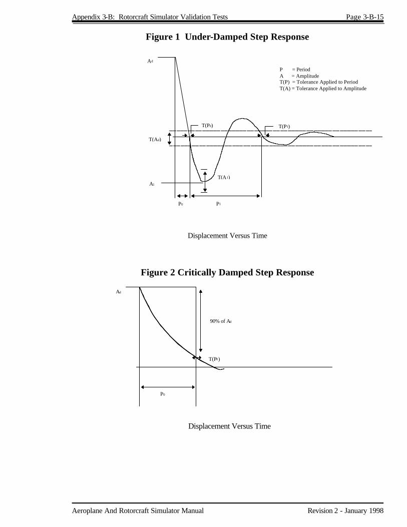
Appendix 3-B: Rotorcraft Simulator Validation Tests Page 3-B-15
Aeroplane And Rotorcraft Simulator Manual Revision 2 - January 1998
Figure 1 Under-Damped Step Response
T(P0) T(P1)
Ad
T(A1)
P0 P1
T(Ad)
A1
P = PeriodA = AmplitudeT(P) = Tolerance Applied to PeriodT(A) = Tolerance Applied to Amplitude
Displacement Versus Time
Figure 2 Critically Damped Step Response
Ad
P0
T(P0)
90% of Ad
Displacement Versus Time
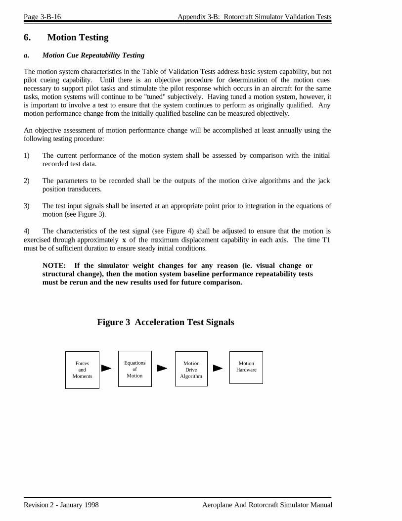
Page 3-B-16 Appendix 3-B: Rotorcraft Simulator Validation Tests
Revision 2 - January 1998 Aeroplane And Rotorcraft Simulator Manual
6. Motion Testing a. Motion Cue Repeatability Testing The motion system characteristics in the Table of Validation Tests address basic system capability, but not pilot cueing capability. Until there is an objective procedure for determination of the motion cues necessary to support pilot tasks and stimulate the pilot response which occurs in an aircraft for the same tasks, motion systems will continue to be "tuned" subjectively. Having tuned a motion system, however, it is important to involve a test to ensure that the system continues to perform as originally qualified. Any motion performance change from the initially qualified baseline can be measured objectively. An objective assessment of motion performance change will be accomplished at least annually using the following testing procedure: 1) The current performance of the motion system shall be assessed by comparison with the initial
recorded test data. 2) The parameters to be recorded shall be the outputs of the motion drive algorithms and the jack
position transducers. 3) The test input signals shall be inserted at an appropriate point prior to integration in the equations of
motion (see Figure 3). 4) The characteristics of the test signal (see Figure 4) shall be adjusted to ensure that the motion is exercised through approximately x of the maximum displacement capability in each axis. The time T1 must be of sufficient duration to ensure steady initial conditions. NOTE: If the simulator weight changes for any reason (ie. visual change or
structural change), then the motion system baseline performance repeatability tests must be rerun and the new results used for future comparison.
Forcesand
Moments
Equationsof
Motion
Figure 3 Acceleration Test Signals
MotionDrive
Algorithm
MotionHardware

Appendix 3-B: Rotorcraft Simulator Validation Tests Page 3-B-17
Aeroplane And Rotorcraft Simulator Manual Revision 2 - January 1998
Acceleration
T1 T2 T3T i m e
F i g u r e 4
b. Alternative Method for Motion Systems Testing An alternative to the procedures described and specified in section 3.A. and B. of the Table of Validation Tests and in subsection 6.a. of this Appendix is "end to end" testing of the motion system and its associated washout, drive and servo systems. An acceptable procedure to conduct the end to end test is, for convenience, described as follows: 1) At the point at which the accelerations from the equation of motion normally excite the motion
system, including the washout algorithms, a sinusoidal input would be used to excite the motion system (see Figure 5). Acceleration at the pilot station would be measured as the output. The test would be done independently in each of the six DOF and the response measured to determine frequency response. The resulting frequency response measured in each axis must comply with the following specification:
Gain ±2db 0.5 Hz to 5.0 Hz Phase 0±20° 1.0 Hz to 2.0 Hz
NOTE: This procedure does not account for the correctness of the algebraic sign
between input and output. Consequently, care must be exercised to ensure that the signs are correct.
2) Motion systems demonstrated by end to end testing must also comply with the displacements
delineated in section 5.
Forcesand
Moments
Equationsof
Motion
Figure 5
MotionDrive
Algori thm
MotionHardware
Input
SineWave
Generator
OutputFrequencyResponseAnalyzer
0 .1 Hz - 20 Hz

Aeroplane And Rotorcraft Simulator Manual Revision 2 - January 1998
Appendix 3-C Functions and Subjective Tests 1. Discussion Functional and subjective tests of simulator characteristics and systems operation will be evaluated at each flight crew member position. As appropriate, these shall include the cockpit check, system operation, normal, abnormal and emergency procedures using the operator's operating procedures and check lists. This assessment is to include operations under the full range of environmental conditions (winds, density altitude, etc.) in which the rotorcraft would normally be expected to perform. Initial evaluation shall include functional checks from this Appendix as appropriate. If required, TC may elect to focus on simulator operation during a special aspect of an operator's training program during the functional check portion of a recurrent evaluation. Such a functional evaluation may include a portion of a LOFT scenario or special emphasis items within the operator's training program. Unless directly related to a requirement for the current certification level, the results of such an evaluation would not affect the simulator's current status. Operational principal navigation systems, including but not limited to, Electronic Flight Instrument Systems (EFIS), Flight Management Systems (FMS), Global Positioning System (GPS) and Initial Navigation Systems (INS) will be evaluated if installed. The ground and flight manoeuvres which shall be evaluated, as appropriate to the level of the simulator and the visual and special effects evaluations, are in the following table. All systems functions will be assessed for normal and, where appropriate, alternate operations. Normal, abnormal and emergency procedures associated with a flight phase will be assessed during the evaluation of manoeuvres or events within that flight phase. Systems are listed separately under "any flight phase" to assure appropriate attention to system checks. 2. Table of Functions and Subjective Tests
Simulator Level
A B C D
1. FUNCTIONS AND MANOEUVRES
A. PREPARATION FOR FLIGHT
1. Pre-flight. Accomplish a functions check of all switches, indicators, systems, and equipment at all cockpit crew members' and instructors' stations and determine that the cockpit design and functions are identical to that of the rotorcraft simulated.
x x x
B. PRE-TAKEOFF
1. APU/Engine start and run-up (a) Normal start procedures (b) Alternate start procedures (c) Abnormal starts and shutdowns (hot start, hung start, etc.) (d) Rotor engagement (e) Systems checks (f) Other
x x x

Page 3-C-2 Appendix 3-C: Functions and Subjective Tests
Revision 2 - January 1998 Aeroplane And Rotorcraft Simulator Manual
Simulator Level
A B C D
2. Ground Taxi. (a) Power required to taxi (b) Brake effectiveness (c) Ground handling (d) Abnormal/emergency procedures, e.g. • Brake system failure • Ground resonance • Other
x x x
3. Hover (a) Takeoff to a hover (b) Instrument response • Engine instruments • Flight instruments (c) Hovering turns (d) Hover power checks • In ground effect (IGE) • Out of ground effect (OGE) (e) Crosswind/tailwind hover (f) Abnormal/emergency procedures, e.g. • Engine failure • Hovering autorotation • Fuel governing system failure • Settling with power (OGE) • Stability system failure • Directional control malfunction • Other (g) Translating tendency (h) External load operations • Hook-up • Release (9) Winch operations
x x
4. Translational Flight (a) Forward (b) Sideward (c) Rearward
x x
C. TAKEOFF
1. Normal (a) From ground (b) From hover • CAT A • CAT B (c) Running (d) Crosswind/tailwind (e) Maximum performance (f) Instrument (g) Confined area (h) Pinnacle/platform (i) Slope (j) External load operations
x x
x x
x x x x x x x x
x x
x x x x x x x x
2. Abnormal/emergency procedures, e.g. (a) Takeoff with engine failure before and after critical decision point (CDP) • CAT A • CAT B (b) Rejected takeoff • Land • Water (if float equipped) (c) Other
x
x
x
x
x
x
x
x
x

Appendix 3-C: Functions and Subjective Tests Page 3-C-3
Aeroplane And Rotorcraft Simulator Manual Revision 2 - January 1998
Simulator Level
A B C D
D. INFLIGHT OPERATION
1. Climb (a) Normal (b) Obstacle clearance (c) Vertical (d) One engine inoperative (e) Other
x x
x x
x x x x x
x x x x x
2. Cruise (a) Performance (b) Flying qualities (c) Turns • Timed • Normal • Steep (d) Accelerations and decelerations (e) High airspeed vibrations (f) External load operations (g) Abnormal/emergency procedures, e.g. • Engine fire • Engine failure • Inflight engine shutdown and restart • Fuel governing system failures • Directional control malfunction • Hydraulic failure • Stability system failure • Rotor vibrations • Other
x x x
x x
x
x x x
x x x x
x x x
x x x x
3. Descent (a) Normal (b) Maximum rate (c) Autorotative • Straight in • With turn (d) Other
x x x
E. APPROACHES
1. Non-precision (a) All engines operating (b) One or more engines inoperative (c) Approach procedures, e.g. • NDB • VOR, RNAV, TACAN • ASR • Circling
** (if requested by operator)
• Rotorcraft only • Other (d) Missed approach • All engines operating • One or more engines inoperative
x x x
**
Simulators with visual systems which permit completing a circling approach without violating FAR § 91.175(e) may be approved for that particular circling approach procedure.

Page 3-C-4 Appendix 3-C: Functions and Subjective Tests
Revision 2 - January 1998 Aeroplane And Rotorcraft Simulator Manual
Simulator Level
A B C D
2. Precision (a) All engines operating (b) One or more engines inoperative (c) Approach procedures, e.g. • PAR • MLS • ILS - Manual (raw data) - Flight director only - Auto pilot coupled - CAT I - CAT II • Other (d) Missed approach • All engines operating • One or more engines inoperative
x x x
3. Visual (a) Normal (b) Steep (c) Shallow (d) CAT A profile (e) CAT B profile (f) External load (g) Visual segment from precision approach (h) Visual segment from circling approach (i) Abnormal/emergency procedures, e.g. • Directional control failure • Hydraulics failure • Fuel governing failure • Autorotation • Stability system failure • Other
x x x x x
x x x
x x x x x x x x x
x x x x x x x x x
F. LANDING
1, Normal (a) From a hover (b) Running (c) Pinnacle/platform (d) Confined area (e) Slope (f) Crosswind/tailwind
x
x
x x x x x x
x x x x x x
2. Abnormal/emergency procedures, e.g. (a) From autorotation (b) One engine inoperative (c) Directional control failure (d) Hydraulics failure (e) Stability system failure (f) Other
x
x x x
x x x x x x
x x x x x x
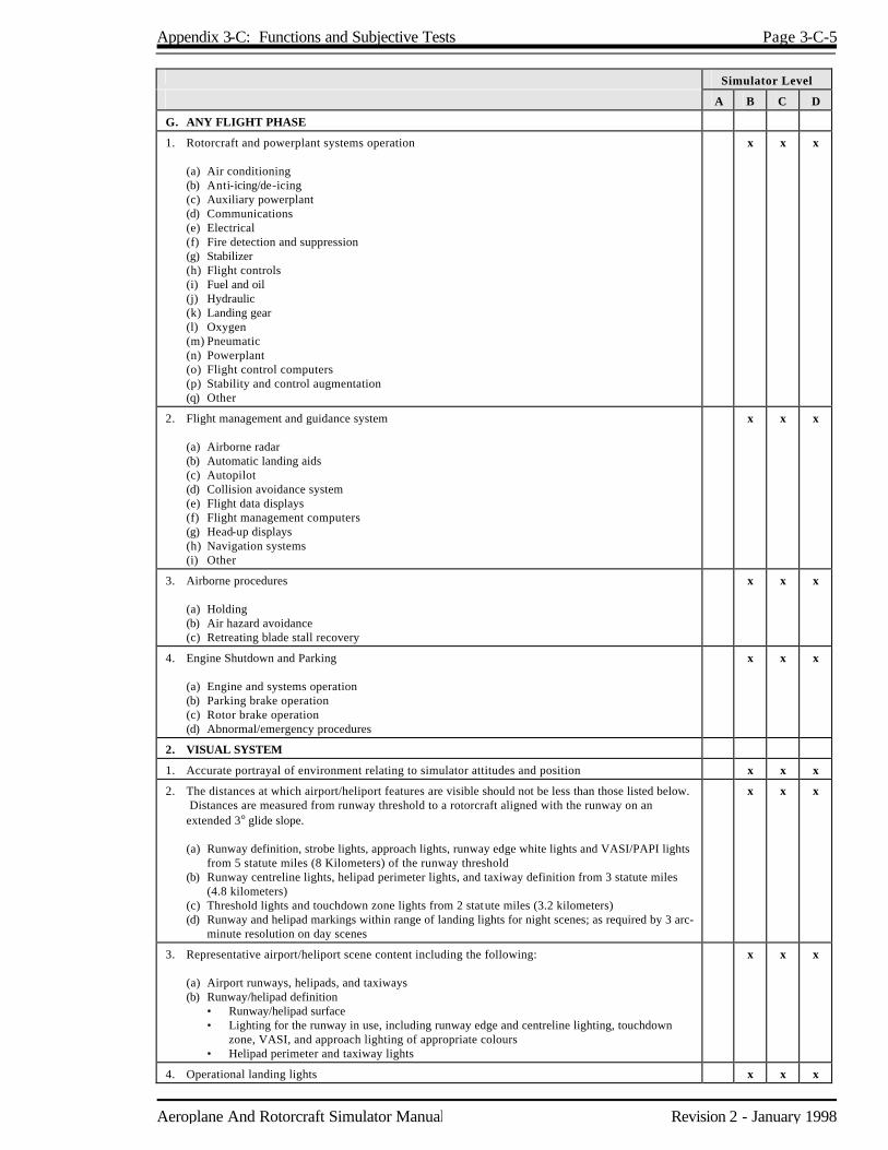
Appendix 3-C: Functions and Subjective Tests Page 3-C-5
Aeroplane And Rotorcraft Simulator Manual Revision 2 - January 1998
Simulator Level
A B C D
G. ANY FLIGHT PHASE
1. Rotorcraft and powerplant systems operation (a) Air conditioning (b) Anti-icing/de-icing (c) Auxiliary powerplant (d) Communications (e) Electrical (f) Fire detection and suppression (g) Stabilizer (h) Flight controls (i) Fuel and oil (j) Hydraulic (k) Landing gear (l) Oxygen (m) Pneumatic (n) Powerplant (o) Flight control computers (p) Stability and control augmentation (q) Other
x x x
2. Flight management and guidance system (a) Airborne radar (b) Automatic landing aids (c) Autopilot (d) Collision avoidance system (e) Flight data displays (f) Flight management computers (g) Head-up displays (h) Navigation systems (i) Other
x x x
3. Airborne procedures (a) Holding (b) Air hazard avoidance (c) Retreating blade stall recovery
x x x
4. Engine Shutdown and Parking (a) Engine and systems operation (b) Parking brake operation (c) Rotor brake operation (d) Abnormal/emergency procedures
x x x
2. VISUAL SYSTEM
1. Accurate portrayal of environment relating to simulator attitudes and position x x x
2. The distances at which airport/heliport features are visible should not be less than those listed below. Distances are measured from runway threshold to a rotorcraft aligned with the runway on an extended 3° glide slope.
(a) Runway definition, strobe lights, approach lights, runway edge white lights and VASI/PAPI lights
from 5 statute miles (8 Kilometers) of the runway threshold (b) Runway centreline lights, helipad perimeter lights, and taxiway definition from 3 statute miles
(4.8 kilometers) (c) Threshold lights and touchdown zone lights from 2 statute miles (3.2 kilometers) (d) Runway and helipad markings within range of landing lights for night scenes; as required by 3 arc-
minute resolution on day scenes
x x x
3. Representative airport/heliport scene content including the following: (a) Airport runways, helipads, and taxiways (b) Runway/helipad definition • Runway/helipad surface • Lighting for the runway in use, including runway edge and centreline lighting, touchdown
zone, VASI, and approach lighting of appropriate colours • Helipad perimeter and taxiway lights
x x x
4. Operational landing lights x x x

Page 3-C-6 Appendix 3-C: Functions and Subjective Tests
Revision 2 - January 1998 Aeroplane And Rotorcraft Simulator Manual
Simulator Level
A B C D
5. Instructor controls of the following: (a) Cloud base-cloud tops (b) Visibility in statute miles (km) and RVR in feet (meters) (c) Airport/heliport selection (d) Airport/heliport lighting
x x x
6. Visual system compatibility with vehicle mathematical model x x x
7. Visual cues to assess sink rate, translational rates, and height AGL during landings x x x
8. Dusk and night visual scene capability (a Surface on runways/helipads, taxiways, and ramps (b) Terrain features
x x
9. Minimum of three specific airport/heliport scenes (a) Surfaces and markings on runways, helipads, taxiways, and ramps (b) Lighting of appropriate colour for all landing areas including runway edge, centreline,
VASI/PAPI, and approach lighting for the runway in use (c) Helipad perimeter and taxiway lighting (d) Ramps and terminal buildings and vertical objects which correspond to an operator's LOFT and
Line Oriented Simulator scenarios (LOS)
.
x x
10. General terrain characteristics and significant landmarks x x
11. At and below an altitude of 2,000 ft. (610 m) height above the airport/heliport and within a radius of 10 miles (16.1 kilometers) from the airport/heliport, weather representations, including the following:
(a) Variable cloud density (b) Partial obscuration of ground scenes; the effect of a scattered to broken cloud deck (c) Gradual break out (d) Patchy fog (e) The effect of fog on airport/heliport lighting
x x
12. A capacity to present ground and air hazards such as another aircraft crossing the active runway and converging airborne traffic
x x
13. Operational visual scenes which provide a cue rich environment sufficient for precise low airspeed/low altitude manoeuvring and landing
x x
14. Operational visual scenes which portray representative physical relationships known to cause landing illusions such as short runways, landing approaches over water, uphill or downhill landing areas, rising terrain on the approach path, and unique topographic features
x
15. Special weather representations of light, medium, and heavy precipitation near a thunderstorm on takeoff, approach, and landing at and below an altitude of 2,000 feet (610 m) above the airport/heliport surface and within a radius of 10 miles (16.1 kilometers) from the airport/heliport
x
16. Wet and snow-covered landing areas including runway/helipad lighting reflections for wet, partially obscured lights for snow, or suitable alternative effects
x
17. Realistic colour and directionality of airport/heliport lighting x
18. Weather radar presentations in rotorcraft where radar information is presented on the pilot's navigation instruments. Radar returns should correlate to the visual scene
x
19. Dynamic visual representation of rotor disk tip path plane x
20. Freedom from apparent quantization (aliasing) x

Appendix 3-C: Functions and Subjective Tests Page 3-C-7
Aeroplane And Rotorcraft Simulator Manual Revision 2 - January 1998
Simulator Level
A B C D
3. SPECIAL EFFECTS
1. Buffet rumble, oleo deflections, effects of ground-speed and uneven surface characteristics x x x
2. Buffet due to transverse flow effect x x x
3. Buffet during extension and retraction of landing gear x x x
4. Buffet due to retreating blade stall x x x
5. Buffet due to settling with power x x x
6. Representative touchdown cues for landing gear x x x
7. Rotor vibrations x x x
8. Representative brake and tire failure dynamics and decreased brake efficiency due to high brake temperatures based on rotorcraft related data.
These representations must be realistic enough to cause pilot identification of the problem and
implementation of appropriate procedures. Simulator pitch, side loading, and directional control characteristics should be representative of the rotorcraft.
x x
9. Sound of precipitation and significant rotorcraft noises perceptible to the pilot during normal operations and the sound of a crash when the simulator is landed in excess of landing gear limitations
Significant rotorcraft noises should include engine, rotor, transmission, landing gear, and other
airframe sounds to a comparable level as that found in a rotorcraft. The sound of a crash should be related in some logical manner to landing in an unusual attitude or in excess of the structural gear limitations of the rotorcraft.
x x
10. Effects of airframe icing (if applicable) x x

Aeroplane And Rotorcraft Simulator Manual Revision 2 - January 1998
Chapter 4 Flight Training Devices 4.1 Classification System 4.1.1 The procedures and criteria for flight training devices qualification are contained in this Chapter.
To be used in an operator's approved training program, any flight training device (FTD) must be qualified by the MSP in accordance with the guidance and standards herein. When used in an approved training program, an FTD will be qualified for a specific operator. Based on a successful evaluation, the MSP will certify that the device meets the criteria of a specific level of qualification. Upon qualification by the MSP, approval for the use of the device in a particular training program will be determined by the Operational Authority in accordance with the Standard that applies with respect to that training program.
4.1.2 Levels of Qualification Level 1 devices are those previously approved and listed in the Pilot Licensing Procedures
Manual (PLPM) dated October 1991 and those devices approved under the provisions of Section 4.9 of TP9685E. Levels 2 and 3 are generic in that they are representative of no specific aircraft cockpit and do not require reference to a specific aircraft. Levels 4 through 7 represent a specific cockpit for the aircraft represented. Within the generic or specific category, each higher level of FTD is progressively more complex. A qualified FTD which is used for a specific training event may also be used for the associated checking event. Because of the increase in complexity and more demanding standards when progressing from Level 2 to Level 7, there is a continuum of technical definition across those levels.
4.2 Evaluation Policy 4.2.1 The FTD must be assessed in the areas critical to the accomplishment of pilot training and
checking events. This includes aerodynamic responses, control checks and performance in take-off, climb, cruise, descent, approach and landing. Crew member stations and instructor station functions checks and certain additional requirements depending on the complexity of the device must be thoroughly assessed. Should a motion system or visual system be contemplated for installation on any level of flight training device, the operator or the manufacturer should contact the MSP for information regarding an acceptable method for measuring motion and/or visual system operation and applicable tolerances. The motion and visual systems, if installed, will be evaluated to ensure their proper operation. It is intended that FTDs be evaluated as objectively as possible. Pilot acceptance, however, is also an important consideration. The device will be subjected to validation tests presented in Appendix 4-B and functions and subjective tests from Appendix 4-C. These tests include a qualitative assessment by a TC pilot who is qualified in the respective aircraft, or set of aircraft in the case of Levels 2 or 3. Validation tests are used to objectively compare training device and aircraft data (or other approved reference data) to assure that they agree within a specified tolerance. Function tests are designed to provide a basis for evaluating FTD capability to perform over a typical training period and to verify correct operation of the controls, instruments and systems.
4.2.2 Tolerances, listed for parameters in Appendix 4-B, should not be confused with design
tolerances specified for FTD manufacturer. Tolerances for the parameters listed in Appendix 4-B are the maximum acceptable to TC for validation of this device.

Page 4-2 Chapter 4: Flight Training Devices
Revision 2 - January 1998 Aeroplane And Rotorcraft Simulator Manual
4.2.3 A convertible FTD will be addressed as a separate device for each model and series to which it
will be converted and TC qualification sought. A TC evaluation is required for each configuration. For example, if an operator seeks qualification for two models of an aircraft type using a convertible device, two QTGs or a QTG and a supplemental QTG are required. Two evaluations are required.
4.2.4 The aircraft manufacturer's flight test data is the accepted standard for initial qualification of
Levels 6 and 7 FTDs due to the specific aircraft aerodynamic programming necessary. Exceptions to this policy may be made but must first be submitted to the MSP for review and consideration.
4.2.5 If flight test data from a source in addition to or independent of the aircraft manufacturer's data
is to be submitted in support of an FTD qualification, it must be acquired in accordance with normally accepted professional flight test methods. Proper consideration for the following must be an intrinsic part of the flight test planning:
a) Appropriate and sufficient data acquisition equipment or system; b) Current calibration of data acquisition equipment and aircraft performance instrumentation
(calibration must be traceable to a recognized standard); c) Flight test plan, including — 1. manoeuvres and procedures, 2. initial conditions, 3. flight conditions, 4. aircraft configuration, 5. weight and centre of gravity, 6. atmospheric ambient and environmental conditions, 7. data required, and 8. other appropriate factors; d) Appropriately qualified flight test personnel; e) Data reduction and analysis methods and techniques; f) Data accuracy (the data must be presented in a format that supports the flight training
device validation); g) Resolution must be sufficient to determine compliance with the tolerances of Appendix 4-B; h) Presentation must be clear with necessary guidance provided; and i) Over-plots must not obscure the reference data.
Chapter 4: Flight Training Devices Page 4-3
Aeroplane And Rotorcraft Simulator Manual Revision 2 - January 1998
4.2.6 The flight test plan should be reviewed with the MSP well in advance of commencing the flight test. After completion of the tests, a flight test report should be submitted in support of the validation data. The report must contain sufficient data and rationale to support qualification of the device at the level requested. 4.2.7 For a new type of model of aircraft, predicted data validated by flight test data which has not
been finalised and made official by the manufacturer, can be used for an interim period. In the event predicted data are used in programming the device, an update should be accomplished as soon as practicable when actual aircraft flight test data become available. Unless specific conditions warrant otherwise, this update should occur within six months after release of the final flight test data package by the aircraft manufacturer.
4.2.8 Levels 2, 3 and 5 FTDs do not require a specific aerodynamic model; however, their
performance must be compared to a reference set of validation data for initial qualification and for repeated recurrent evaluations. Note: Level 4 requires no aerodynamic model. In the absence of a specific model, these devices may use a generic model typical of the set of aircraft as described in this Chapter. For example, a twin engine, turbojet transport aircraft FTD must demonstrate the performance and handling typical of that set of aircraft. Similarly, a light twin or single engine aircraft FTD must demonstrate performance typical of the respective set of aircraft. The aerodynamic model may be one representing an actual aircraft within that set of aircraft or it may be created or derived using the same mathematical expressions as those used in a specific model but with coefficient values which are not obtained from flight test results for a particular aircraft. Instead, the coefficient values could be fictitious but be typical of the set of aircraft replicated. The reference validation data could then be created by doing a computer simulation, using these fictitious coefficients. A generic model may also be acquired from public domain resources or it may be a composite of various models, none of which is complete within itself. It is the responsibility of the operator to demonstrate that the reference data used represents the appropriate set of aircraft. To assure that the device continues to comply with its original qualifications status, it will then be compared to the reference data for subsequent recurrent evaluations. Once reference data for a specific set of aircraft is accepted by the MSP, this data will be considered accepted for that set of aircraft without a requirement for further review and approval.
4.2.9 Evaluation dates will not be established until the QTG has been reviewed by TC and determined
to be acceptable in accordance with this Manual. 4.2.10 During evaluations, the operator's pilots may assist in the accomplishment of the functions and
validation tests at the discretion of TC; however, only TC personnel should manipulate the pilot controls during the functions check portion of a TC evaluation.
4.2.11 TC evaluations of FTDs located outside of Canada will be performed if the device is used by an
operator in satisfying any training or checking requirements. Evaluations may be conducted otherwise as deemed appropriate by the Minister on a case-by-case basis.
4.2.12 Upon qualification of the FTD, approval for the use of the device in a particular training program
will be determined by the Operational Authority in accordance with the Standard that applies with respect to that training program.

Page 4-4 Chapter 4: Flight Training Devices
Revision 2 - January 1998 Aeroplane And Rotorcraft Simulator Manual
4.3 Initial or Upgrade Evaluations 4.3.1 An operator seeking FTD initial or upgrade evaluation must submit a request in writing to the
MSP through the appropriate regional office. All requests should contain a compliance statement certifying that the device meets all provisions of this Chapter, that the cockpit configuration conforms to that of the aircraft, that specific hardware and software configuration control procedures have been established and that the pilot(s) designated by the operator confirm that it is representative of the aircraft in all appropriate functions test areas.
4.3.2 The operator should submit a QTG which includes: a) A title page with the operator and TC signature blocks; b) A FTD information page, for each configuration in the case of convertible devices,
providing the following information, if applicable — 1. the operator's FTD identification number or code, 2. aircraft, or set of aircraft, as appropriate, being simulated, 3. source of aerodynamic data and any appropriate revision reference, 4. engine model (and data revision, as applicable) if appropriate, 5. flight control data revision, if appropriate, 6. flight management system identification (and revision level, if appropriate), 7. FTD model and manufacturer, 8. date of device manufacture, 9. computer identification, if appropriate, 10. visual system model and manufacturer, if installed, and 11. motion system type and manufacturer, if installed; c) Table of Contents; d) Log of revision and/or list of effective pages; e) Listing of all other reference or source data, if applicable; f) Glossary of terms and symbols used; g) Statements of Compliance (SOC) as may be required in Appendix 4-A, "Flight Training
Device Standards", comments column - SOC requirements; h) A list of equipment required to accomplish the validation tests and a description of the
appropriate procedures to be followed to record the test results. If testing and recording is to be accomplished automatically, a listing of the equipment and appropriate procedures should be included; and
i) The following is needed for each validation test designated in Appendix 4-B: 1. name of the test, 2. objective of the test, 3. initial conditions, 4. method for evaluating validation test results, 5. tolerances for relevant parameters, 6. source of validation reference data, 7. copy of validation reference data, 8. validation test results as obtained by the operator, and 9. a means, acceptable to DOT of easily comparing the training device test results to

Chapter 4: Flight Training Devices Page 4-5
Aeroplane And Rotorcraft Simulator Manual Revision 2 - January 1998
validation reference data. 4.3.3 Test results should be labelled using terminology common to aircraft parameters as opposed to
computer software identifications or other references. These results should be easily compared to the supporting data by employing cross plotting, overlays, transparencies or other acceptable means. Use of multi-channel recorder, line printer or similar recording media is encouraged for all FTD levels; however, regardless of the media used, it must be acceptable to TC. Data reference documents included in a QTG may be photographically reduced only if such reduction will not alter the graphic scaling or cause difficulties in scale interpretation or resolution. Incremental scales on graphical presentations must provide the resolution necessary for evaluation of the parameters shown in Appendix 4-B. The test guide will provide the documented proof of compliance with the validation tests in Appendix 4-B. In the case of an upgrade, an operator should run the validation tests for the requested qualification level. Validation test results offered in a test guide for a previous initial or upgrade evaluation should not be offered to validate FTD performance as part of a test guide offered for an upgrade. FTD test results should be clearly marked with appropriate reference points to ensure an accurate comparison between training device and validation reference data with respect to time when tests involve time history parameters. Operators using line printers to record time histories should clearly mark that information taken from the line printer data output for cross-plotting on the aircraft data. The cross-plotting of the operator's FTD data to the reference data is essential to verify performance in each test. During an evaluation, TC will devote its time to detailed checking of selected tests from the QTG. The TC evaluation serves to validate the operator's test results.
4.3.4 The complete QTG and the operator's compliance letter and request for the evaluation will be
submitted to the MSP. The QTG will be reviewed and determined to be acceptable prior to scheduling an evaluation of the device.
4.3.5 A copy of an MQTG for each type FTD (Levels 6 and 7 only) by each manufacturer will be
required for the MSP file . The MSP may elect not to retain copies of the QTG for subsequent devices of the same type by a particular manufacturer but will determine the need for copies on a case-by-case basis. Data updates to an original QTG should be provided to the MSP in order to keep TC file copies current.
4.3.6 The operator may elect to accomplish the QTG validation tests while the FTD is at the
manufacturer's facility. Tests at the manufacturer's facility should be accomplished at the latest practical time prior to disassembly and shipment. The operator must then validate the performance of the device at the final location by repeating at least 1/3 of the validation tests in the QTG and submitting those tests to the MSP. After review of these tests, TC will schedule an initial evaluation. The QTG must be clearly annotated to indicate when and where each test was accomplished.

Page 4-6 Chapter 4: Flight Training Devices
Revision 2 - January 1998 Aeroplane And Rotorcraft Simulator Manual
4.3.7 In the event an operator moves an FTD to a new location and its level of qualification is not changed, the following procedures shall apply:
a) Advise the MSP prior to the move; b) Prior to returning the FTD to service at the new location, the operator should perform a
typical recurrent validation and functions test. The results of such tests will be retained by the operator and be available for inspection by TC at the next evaluation or as requested; and
c) TC may schedule an evaluation prior to return to service. 4.3.8 When there is a change of operator, the new operator must accomplish all required
administrative procedures including the submission of the currently approved QTG to the MSP. The QTG must be identified with the new operator by displaying the operator's name or logo. The FTD may, at the discretion of the MSP, be subject to an evaluation in accordance with the original qualification criteria.
4.3.9 The scheduling priority for initial and upgrade evaluations will be based on the sequence in which
acceptable QTGs and evaluation requests are received by TC. 4.3.10 The QTG will be approved after completion of the initial or upgrade evaluation and all
discrepancies in the QTG have been corrected. This document, after inclusion of the TC-witnessed test results, becomes the Master Qualification Test Guide (MQTG). The MQTG will then remain in the custody of the operator for use in future recurrent evaluations.
4.4 Recurrent Evaluations 4.4.1 For a FTD to retain its qualification, it will be evaluated on a recurrent basis using the approved
MQTG. Each recurrent evaluation will consist of functions tests and at least a portion of the validation tests in the MQTG.
4.4.2 The recurrent evaluations will be planned for every six months with approximately one-half of
the validation tests in the MQTG accomplished each time. This will allow all MQTG tests to be accomplished annually. For levels 2, 3 and 4, the interval may be based on annual evaluations by TC with all MQTG tests accomplished at each successive evaluation.
4.4.3 Dates of recurrent evaluations will normally not be scheduled beyond 30 days of the due date. 4.4.4 In the interest of conserving training device time, the following Optional Test Program (OTP),
applicable to Levels 6 and 7, is an alternative to the standard recurrent evaluation procedure: a) Operators having the appropriate automatic recording and plotting capabilities may apply for
evaluation under the OTP;
Chapter 4: Flight Training Devices Page 4-7
Aeroplane And Rotorcraft Simulator Manual Revision 2 - January 1998
b) Operators must notify the MSP in writing of their intent to enter the OTP. If TC determines that the evaluation can be accommodated with four hours or less of training device time, recurrent evaluations for that device will be planned for four hours. If the four-hour period is or will be exceeded and the operator cannot extend the period, the evaluation will be terminated and must be completed within 30 days to maintain qualification status. TC will then reassess the appropriateness of the OTP; and
c) Under the OTP, at least one-third of all validation tests will be performed and certified by
operator personnel between TC recurrent evaluations. Complete coverage will be required through any two consecutive recurrent evaluations. These tests and the recording of the results should be accomplished within the 30 days prior to the scheduled evaluation or accomplished on an evenly distributed basis during the six-month period preceding the scheduled evaluation. This information will be reviewed by the TC Simulator Evaluation Specialist at the outset of each recurrent evaluation. At least twenty per cent of those tests conducted by the operator for each recurrent evaluation will then be selected and repeated by the Simulator Evaluation Specialist along with at least ten per cent of those tests not performed by the operator.
4.4.5 In instances where an operator plans to remove a FTD from active status for prolonged periods,
the following procedures shall apply: a) TC shall be advised in writing. The notice shall contain an estimate of the period that the
device will be inactive; b) Recurrent evaluations will not be scheduled during the inactive period. TC will remove the
FTD from qualified status on a mutually established date not later than the date on which the first missed recurrent evaluation would have been scheduled;
c) Before a device can be restored to TC-qualified status, it will require an evaluation by TC.
The evaluation content and time required for accomplishment will be based on the number of recurrent evaluations missed during the inactive period. For example, if the training device were out of service for one year, it would be necessary to complete the entire test guide since under the recurrent evaluation program, the MQTG is to be completed annually;
d) The operator will notify TC of any changes to the original scheduled time out of service;
and e) The FTD will normally be requalified using the TC-approved MQTG and criteria that was
in effect prior to its removal from qualification; however, inactive periods exceeding one year will require a review of the qualification basis and, if conditions warrant, may require the establishment of a new qualification basis.
4.5 Special Evaluations 4.5.1 Between recurring evaluations, if deficiencies are discovered or it becomes apparent that the
FTD is not being maintained to initial qualification standards, a special evaluation may be conducted by the MSP to verify its status.
Page 4-8 Chapter 4: Flight Training Devices
Revision 2 - January 1998 Aeroplane And Rotorcraft Simulator Manual
4.5.2 The FTD will lose its qualification when the MSP can no longer ascertain maintenance of the original validation criteria based on a recurrent or special evaluation. Additionally, the MSP shall advise the operator if a deficiency is jeopardizing training requirements and arrangements shall be made to resolve the deficiency in the most effective manner, including the withdrawal of approval by the MSP.
4.6 Modification of FTDs 4.6.1 Operators must notify the MSP at least 21 days prior to making software program or hardware
changes which impact flight or ground dynamics. A complete list of these planned changes and identification of proposed updates to the MQTG, must be provided in writing. Operators should maintain a configuration control system to ensure the continued integrity of the device and to account for changes incorporated.
4.6.2 Modifications which impact flight or ground dynamics, systems functions and significant QTG
revisions may require a TC evaluation of the FTD. 4.7 Qualification Basis 4.7.1 Training devices must maintain their performance, functions and other characteristics as
originally evaluated and qualified. All recurrent evaluations of those FTDs using the acceptable methods of compliance described in this Chapter for initial or upgrade evaluation (including any visual or motion system installation) will be conducted in accordance with the provisions herein.
4.8 Downgrade of an Aircraft Simulator to an Aircraft FTD 4.8.1 An operator may elect to have a currently qualified airplane simulator reclassified as an FTD.
This may be accomplished through one of two methods. 4.8.1.1 Normal The operator will follow the steps outlined in this Chapter for the evaluation and qualification of
an FTD irrespective of the device's current status as an aircraft simulator. 4.8.1.2 Administrative The operator would request that the currently qualified airplane instructor be downgraded to an
FTD. This process would not require an on site evaluation of the device and would be in accordance with the following conditions and procedures:
a) Conditions 1. A Level C or D aircraft simulator may be administratively reclassified as a Level 6 or
Level 7 aircraft FTD, at the operator's option. A Level A or B aircraft simulator may be administratively reclassified as a Level 6 FTD;

Chapter 4: Flight Training Devices Page 4-9
Aeroplane And Rotorcraft Simulator Manual Revision 2 - January 1998
2. The existing qualification basis for the simulator will remain the basis for qualification of the FTD, including all aspects of the MQTG, except for those tests applicable to the motion or visual system. The motion and visual systems should be deactivated, although physical removal from the device is not required. Should the operator wish to have the availability of either the motion or visual system, those appropriate tests would remain a part of the MQTG for the FTD; and
3. Frequency and content of recurrent evaluations would remain unchanged except for MQTG modifications that may occur under the above paragraph. b) Procedures 1. The operator must notify the MSP, in writing, of the desire to administratively
downgrade their simulator; 2. This notification must include appropriate page changes to the current MQTG
indicating, at least, the change in status and the elimination of appropriate tests as described under paragraph two of Conditions, above; and
3. After review of this notification package and concluding that the modified MQTG
would support the FTD qualification level sought, the MSP shall issue a qualification letter.
4.9 Previously Approved FTDs 4.9.1 Those FTDs approved in the PLPM dated October 1991 retain their approved status as Level 1
devices. Approval of new devices of these types are subject to the conditions of this manual. 4.9.2 Operators of FTDs which, for any reason, are not capable of meeting, or it is not desired that
they meet, the qualification standards for a specified level as described in this Chapter but which have been previously approved for use will be eligible for evaluation and qualification under a temporary status. This temporary status will remain valid until January 1, 1997.
4.9.3 Operators who desire to have an FTD qualified under this temporary status must make a written
request of the MSP. This request must be made in sufficient time to allow an evaluation (see paragraph below) to be conducted within one year of the effective date of this Chapter or within one year of the in-service date of the device, whichever is later.
4.9.4 In turn, a TC specialist will evaluate the device using as a guide, the previous approval and any
specific instructions or other guidance material provided by the MSP. Only those manoeuvres or procedures previously authorized will be evaluated. The capability to satisfactorily accomplish at least one manoeuvre or procedure must be determined in order to grant qualification.
4.9.5 If the device is satisfactory, the MSP will write a letter of qualification to the operator/sponsor of
the FTD. This qualification letter will: a) State that the FTD is qualified under this temporary status for a period of time not to
exceed January 1, 1997.

Page 4-10 Chapter 4: Flight Training Devices
Revision 2 - January 1998 Aeroplane And Rotorcraft Simulator Manual
b) Include a list of the manoeuvres and procedures that the FTD is capable of performing; and c) Be contingent upon satisfactory recurrent functional evaluation on an annual basis.

Appendix 4-A: Flight Training Device Standards Revision 2 - January 1998
Appendix 4-A Flight Training Device Standards 1. Discussion This Appendix describes the minimum flight training device requirements for qualification at Levels 1 through 7. Appropriate Canadian Aviation Regulations must be consulted when considering particular training device requirements. The validation and functional tests listed in Appendices 4-B and 4-C must also be consulted when determining the requirements of a specific level training device. In the following tabular listing of flight training device standards, needed statements of explanation are indicated in the comments column. These standards are written to apply to aeroplanes. For rotorcraft FTDs, these standards will be amended on a case-by-case basis as appropriate to a rotorcraft device. 2. Flight Training Device General
STANDARDS LEVEL COMMENTS
1 2 3 4 5 6 7
a. A cockpit which will have actuation of controls and switches which replicate those in the aeroplane.
x* x x * Level 3 must be representative of a single set of aeroplanes and must have navigation controls, displays and instrumentation as set out in the CARs for IFR operations.
b. Instruments, equipment, panels, systems and controls sufficient for the training/checking events to be accomplished must be located in a spatially correct open flight deck area. Actuation of these controls and switches must replicate those in the aeroplane.
x* x x * Level 2 must be representative of a single set of aeroplanes. Levels 2 and 5 require simulated aerodynamic capability and control forces and travel sufficient to manually fly an instrument approach.
c. Daily pre-flight documentation. x x x x x x
d. Lighting environment for panels and instruments must be sufficient for the operation being conducted.
x x x x x x* * Lighting must be as per aeroplane lighting for Level 7.
e. Circuit breakers should function accurately when they are involved in operating procedures or malfunctions requiring or involving flight crew response.
x x x x x* x* * Must be properly located in Levels 6 and 7.
f. Effect of aerodynamic changes for various combinations of drag and thrust normally encountered in flight, including the effect of change in aeroplane attitude, thrust, drag, altitude, temperature and configuration.
x x* x x* x* * Levels 3, 6 and 7 require, additionally, the effects of gross weight and centre of gravity.
g. Digital or analogue computing of sufficient capacity to conduct complete operation of the device including its evaluation and testing.
x x x x x

Page 4-A-2 Aeroplane And Rotorcraft Simulator Manual
Revision 2 - January 1998 Appendix 4-A: Flight Training Device Standards
STANDARDS LEVEL COMMENTS
1 2 3 4 5 6 7
h. All relevant instrument indications involved in the simulation of the applicable aeroplane entirely automatic in response to control input.
x x x x x
i. Navigation equipment corresponding to that installed in the replicated aeroplane with operation within the tolerances prescribed for the actual airborne equipment.
x x* x x* x* * Levels 3, 6 and 7 must also include communication equipment (interphone and air/ground) corresponding to that installed in the replicated aeroplane and, if appropriate to the operation being conducted, an oxygen mask microphone/communication system. Levels 2 and 5 need have operational only that navigation equipment sufficient to fly a non-precision instrument approach.
j. Crew member seats must afford the capability for the occupant to be able to achieve the design eye reference position for specific aeroplanes, or to approximate such a position for a generic set of aeroplanes.
x x x x Level 7 crew member seats must accurately simulate those installed in the aeroplane.
k. In addition to the flight crew member stations, suitable seating arrangements for an instructor/check airperson and TC inspector. These seats must provide an adequate view of crew member's panel(s).
x x x x x x These seats need not be a replica of an aeroplane seat and can be as simple as an office chair placed in an appropriate position.
l. Installed system(s) must simulate the applicable aeroplane system operation, both on the ground and in flight. At least one aeroplane system must be represented. System(s) must be operative to the extent that applicable normal, abnormal and emergency operating procedures included in the operator's training program can be accomplished.
x* x* x x* x* x* * Levels 6 and 7 must simulate all applicable aeroplane flight, navigation and systems operation.
* Level 3 must have flight and
navigational controls, displays and instrumentation for powered aircraft as set out in the CARs for IFR operation.
* Levels 2 and 5 must have
functional flight and navigational controls, displays and instrumentation.
m. Instructor controls that permit activation of normal, abnormal and emergency conditions, as may be appropriate. Once activated, proper system operation must result from system management by the crew and not require input from the instructor controls.
x x x x x x
n. Control forces and control travel which correspond to that of the replicated aeroplane or set of aeroplanes. Control forces should react in the same manner as in the aeroplane or set of aeroplanes under the same flight conditions.
x* x x* x x * Levels 2 and 5 need control forces and control travel only of sufficient precision to manually fly an instrument approach.
o. Significant cockpit sounds which result from pilot actions corresponding to those of the aeroplane.
x x x

Aeroplane And Rotorcraft Simulator Manual Page 4-A-3
Appendix 4-A: Flight Training Device Standards Revision 2 - January 1998
STANDARDS LEVEL COMMENTS
1 2 3 4 5 6 7
p. Sound of precipitation, windshield wipers and other significant aeroplane noises perceptible to the pilot during normal, abnormal or emergency operations, as may be appropriate.
x Statement of Compliance.
q. Aerodynamic modelling which, for aeroplanes issued an original type certificate after June 1980, includes low-altitude level-flight ground effect, Mach effect at high altitude, effects of airframe icing, normal dynamic thrust effect on control surfaces, aeroelastic representations and representations of non-linearities due to sideslip based on aeroplane flight test data provided by the manufacturer.
x Statement of Compliance. Tests required. See Appendix 4-B for further information. The SOC must address ground effect, Mach effect, aeroelastic representations and non-linearities due to sideslip. Separate tests for thrust effects and demonstration of icing effects are required.
r. Control feel dynamics which replicate the aeroplane simulated. Free response of the controls shall match that of the aeroplane within the tolerance given in Appendix 4-B. Initial and upgrade evaluation will include control free response (column, wheel and pedal) measurements recorded at the controls. The measured responses must correspond to those of the aeroplane in take-off, cruise and landing configurations.
(1) For aeroplanes with irreversible control
systems, measurements may be obtained on the ground if proper pitot static inputs are provided to represent conditions typical of those encountered in flight. Engineering validation or aeroplane manufacturer rationale will be submitted as justification to ground test or omit a configuration.
(2) For flight training devices requiring
static and dynamic tests at the controls, special test fixtures will not be required during initial evaluations if the operator's QTG shows both test fixture results and alternate test method results, such as computer data plots, which were obtained concurrently. Repeat of the alternate method during the initial evaluation may then satisfy this test equipment.
x Statement of Compliance. Tests required. See Appendix 4-B, section 4.
s. Aerodynamic and ground reaction modelling for the effects of reverse thrust on directional control.
x Statement of Compliance. Tests required.
t . Timely permanent update of flight training device hardware and programming consistent with aeroplane modifications.
x x x x x x
u. Visual system; if installed (not required). x x x x x x Visual system standards set out in this manual for at least basic simulators will be acceptable.
v. Motion system; if installed (not required). x x x x x x Motion system standards set out in this manual for at least basic simulators will be acceptable.

Aeroplane And Rotorcraft Simulator Manual Revision 2 - January 1998
Appendix 4-B Flight Training Device Validation Tests 1. Discussion Performance must be objectively evaluated by comparing the results of tests conducted in the training device to aircraft flight test data unless specifically noted otherwise. The QTG provided by the operator must describe clearly and distinctly how the FTD will be set up and operated for each test. Use of a driver program designed to automatically accomplish the tests is encouraged for all FTDs. A manual test procedure with explicit and detailed steps for completion of each test must also be provided. The tests and tolerances contained in this Appendix must be included in the operator's QTG. The Table of Validation Tests of this Appendix generally indicates the test results required. Unless noted otherwise, tests should represent aircraft performance and handling qualities at normal operating weights and centres of gravity (cg). If a test is supported by aircraft data at one extreme weight or cg, another test supported by aircraft data at mid conditions or as close as possible to the other extreme should be included. Certain tests which are relevant only at one extreme cg or weight condition need not be repeated at the other extreme. It should be recognized that the tests listed in the table merely sample, on a very limited basis, the FTD performance and handling qualities. The results of these tests for Levels 3, 6 and 7 are expected to be indicative of the device's performance and handling qualities throughout the aircraft weight and centre of gravity envelope, the operational envelope and for varying atmospheric ambient and environmental conditions to the extremes authorized for the respective aeroplane or set of aircraft. It is not sufficient, nor is it acceptable, to program these FTDs so that the modelling is correct only at the validation test points. Test of handling qualities must include validation of augmentation devices. FTDs for highly augmented aeroplanes will be validated both in the unaugmented configuration (or failure state with the maximum permitted degradation in handling qualities) and the augmented configuration. Where various levels of handling qualities result from failure states, validation of the effect of the failure is necessary. Requirements for testing will be mutually agreed to between the operator and the MSP in a case-by-case basis. These FTD standards are designed to apply to aeroplanes. For rotorcraft FTDs, appropriate substitutions, omissions and additions to this test list will occur at the discretion of the MSP. 2. Test Requirements The ground and flight tests required for qualification are listed in the Table of Validation Tests. Results of these tests should be available in a form which can be compared to validation reference data. For those devices listed in the following table requiring "generic" aerodynamic modelling, the TC approved data supplied by the manufacturer or the operator sponsoring the device will be used as the comparison basis for objective testing. Flight test data which exhibit rapid variations of the measured parameters may require engineering judgement when making assessments of simulator validity. Such judgement must not be limited to a single parameter. Such judgement must not be limited to a single parameter. All relevant parameters related to a given manoeuvre or flight condition must be provided to allow overall interpretation. When it is difficult or impossible to match data throughout a time history, differences must be justified by providing a comparison of other related variables for the condition being assessed.

Page 4-B-2 Appendix 4-B: Flight Training Device Validation Tests
Revision 2 - January 1998 Aeroplane And Rotorcraft Simulator Manual
Parameters, Tolerances and Flight Conditions The Validation Tests section of this Appendix describes the parameters, tolerances and flight conditions for training device validation. If a flight condition or operating condition is shown which does not apply to the qualification level sought, it should be disregarded. Results must be labelled using the tolerances and units given. Flight Conditions Verification When comparing the parameters listed to those of the aeroplane, sufficient data must also be provided to verify the correct flight conditions. For example, to show that control force is within ±5 lbs (2.225 daN) in a static stability test, data to show the correct airspeed, power, thrust or torque, aeroplane configuration, altitude and other appropriate datum identification parameters shall also be given. If comparing short period dynamics, normal acceleration may be used to establish a match to the aeroplane, but airspeed, altitude, control input, aeroplane configuration and other appropriate data shall also be given. All airspeed values shall be clearly annotated as to indicated, calibrated, etc., and like values used for comparison. 3. Table of Validation Tests
Test Tolerance Flt Condition Qualification Requirement Comments
1 2 3 4 5 6 7
1. PERFORMANCE
A. Take-off
1. Ground Acceleration Time
±5% Time or ±1 Second
Ground/Take-off
x x x* * Level 7 devices will require distance measurements also. Tolerances will be ±5% time and distance or ±5% time and +200 feet (60m) of distance.
2. Minimum Unstick Speed (or equivalent as provided by the aircraft manufacturer)
±3 Knots Airspeed ±1.5° Pitch
Ground/Take-off
x Vmu is defined as that speed at which the last main landing gear leaves the ground.
3. Normal Take-off
±3 Knots Airspeed ±1.5° Pitch ±1.5° Angle of Attack ±20 feet (6m) Altitude
Ground/Take-off and First Segment Climb
x x
4. Critical Engine Failure on Take-off
3 Knots Airspeed ±1.5° Pitch or ±1.5° Angle of Attack ±20 feet (6m) Altitude ±2° Bank and Sideslip Angle
Ground/Take-off and First Segment Climb
x
5. Crosswind Take-off
3 Knots Airspeed ±1.5° Pitch or ±1.5° Angle of Attack ±20 feet (6m) Altitude ±2° Bank and Sideslip Angle
Ground/Take-off and First Segment Climb
x
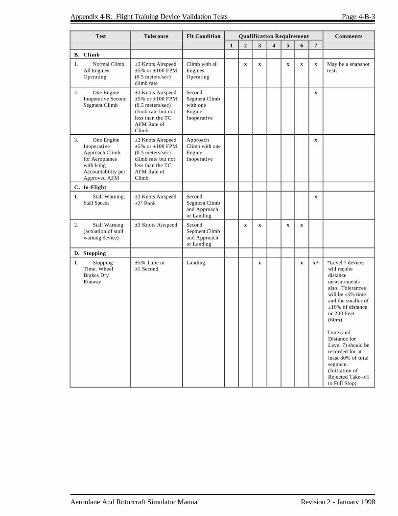
Appendix 4-B: Flight Training Device Validation Tests Page 4-B-3
Aeroplane And Rotorcraft Simulator Manual Revision 2 - January 1998
Test Tolerance Flt Condition Qualification Requirement Comments
1 2 3 4 5 6 7
B. Climb
1. Normal Climb All Engines Operating
±3 Knots Airspeed ±5% or ±100 FPM (0.5 meters/sec) climb rate
Climb with all Engines Operating
x x x x x May be a snapshot test.
2. One Engine Inoperative Second Segment Climb
±3 Knots Airspeed ±5% or ±100 FPM (0.5 meters/sec) climb rate but not less than the TC AFM Rate of Climb
Second Segment Climb with one Engine Inoperative
x
3. One Engine Inoperative Approach Climb for Aeroplanes with Icing Accountability per Approved AFM
±3 Knots Airspeed ±5% or ±100 FPM (0.5 meters/sec) climb rate but not less than the TC AFM Rate of Climb
Approach Climb with one Engine Inoperative
x
C. In-Flight
1. Stall Warning, Stall Speeds
±3 Knots Airspeed ±2° Bank
Second Segment Climb and Approach or Landing
x
2. Stall Warning (actuation of stall warning device)
±3 Knots Airspeed Second Segment Climb and Approach or Landing
x x x x
D. Stopping
1. Stopping Time, Wheel Brakes Dry Runway
±5% Time or ±1 Second
Landing x x x* *Level 7 devices will require distance measurements also. Tolerances will be ±5% time and the smaller of ±10% of distance or 200 Feet (60m). Time (and Distance for Level 7) should be recorded for at least 80% of total segment. (Initiation of Rejected Take-off to Full Stop).

Page 4-B-4 Appendix 4-B: Flight Training Device Validation Tests
Revision 2 - January 1998 Aeroplane And Rotorcraft Simulator Manual
Test Tolerance Flt Condition Qualification Requirement Comments
1 2 3 4 5 6 7
2. Stopping Time, Reverse Thrust, Dry Runway
±5% Time or ±1 Second
Landing x x x* *Level 7 devices will require distance measurements also. Tolerances will be ±5% time and the smaller of ±10% of distance or 200 Feet (60m). Time (and Distance for Level 7) should be recorded for at least 80% of total segment. (Initiation of Rejected Take-off to Full Stop).
3. Stopping Time and Distance, Wheel Brakes, Wet Runway
Representative Stopping Time and Distance
Landing x Time and Distance should be recorded for at least 80% of total segment (Initiation of RTO to Full Stop). TC approved AFM data is acceptable.
4. Stopping Time and Distance, Wheel Brakes, Icy Runway
Representative Stopping Time and Distance
Landing x Time and Distance should be recorded for at least 80% of total segment (Initiation of RTO to Full Stop). TC approved AFM data is acceptable.
E. Engines
1. Acceleration ±10% Time Approach or Landing
x* x* x* x x *Tolerances of ±1 second authorized for Levels 2, 3 and 5. Test from flight idle to go-around power.
2. Deceleration ±10% Time Ground/Take-off
x* x* x* x x *Tolerances of ±1 second authorized for Levels 2, 3 and 5. Test from maximum take-off power to 10% of maximum take-off power (90% decay in power available above idle).
2. HANDLING QUALITIES
A. Static Control Checks**
**
Column, wheel and pedal position versus force shall be measured at the control. An alternative method acceptable to the MSP in lieu of the test fixture at the controls would be to instrument the training device in an equivalent manner to the flight test aeroplane. The force and position data from this instrumentation can be directly recorded and matched to the aeroplane data. Such a permanent installation could be used without any time for installation of external devices.

Appendix 4-B: Flight Training Device Validation Tests Page 4-B-5
Aeroplane And Rotorcraft Simulator Manual Revision 2 - January 1998
Test Tolerance Flt Condition Qualification Requirement Comments
1 2 3 4 5 6 7
1. Column Position Versus Force and Surface Position Calibration
±2 lbs (0.89 daN) Breakout ±5 lbs (2.224 daN) or ±10% Force ±2° Elevator
Ground x x Uninterrupted control sweep.
Column Position Versus Force
±2 lbs (0.89 daN) Breakout ±5 lbs (2.224 daN)
x x x
2. Wheel Position Versus Force and Surface Position Calibration
±2 lbs (.89 daN) Breakout ±3 lbs (1.334 daN) or ±10% Force ±2° Rudder
Ground x x Uninterrupted control sweep
Wheel Position Versus Force
±2 lbs (.89 daN) Breakout ±3 lbs (1.334 daN) or ±10% Force
x x x .
3. Pedal Position Versus Force and Surface Position Calibration
± 5 lbs (2.224 daN) Breakout ±5 lbs (2.224 daN) or ±10% Force ±2° Rudder
Ground x x Uninterrupted control sweep
Pedal Position Versus Force
±5 lbs (2.224 daN) Breakout ±5 lbs (2.224 daN) or ±10% Force
x x x .
4. Nosewheel Steering Force
±2 lbs (.89 daN) Breakout ±3 lbs (1.33 daN) or ±10% Force
Ground x x x If appropriate to the aircraft or "collection" of aircraft being simulated.
5. Rudder Pedal Steering Calibration
±2° Nosewheel Angle
Ground x x x If appropriate to the aircraft or "collection" of aircraft being simulated.
6. Pitch Trim Calibration Indicator Versus Computed
±0.5° of Computed Trim Angle
Ground x x
7. Alignment of Power Lever (or Cross Shaft Angle) Versus Selected Engine Parameter (i.e., EPR, N1, Torque, Manifold Pressure, etc.)
±5° of Power Lever Angle or Cross Shaft Angle or Equivalent
Ground x x Computer output results may be used to show compliance with engine model data.
8. Brake Pedal Position Versus Force
±2° Pedal Position ±5 lb (2.224 daN) or 10%
Ground x* x* x *Levels 3 and 6 only need data points at zero and maximum braking application.

Page 4-B-6 Appendix 4-B: Flight Training Device Validation Tests
Revision 2 - January 1998 Aeroplane And Rotorcraft Simulator Manual
Test Tolerance Flt Condition Qualification Requirement Comments
1 2 3 4 5 6 7
B. Dynamic Control Checks**
1. Pitch Control ±10% Time for Each Zero Crossing ±10% Amplitude of First Overshoot ±20% of Amplitude of second and subsequent overshoots greater than 5% of Initial Displacement. ±1 Overshoot.
Take-off, Cruise, Landing
x Data should be normal control displacement in both directions. Approximately 25% to 50% of full throw. Refer to section 4 of this Appendix.
2. Roll Control Same as 1. above. Take-off, Cruise, Landing
x
3. Yaw Control Same as 1. above Take-off, Cruise, Landing
x
C. Longitudinal
1. Power Change Dynamics
±3 Knots Airspeed ±100 Feet (30m) Altitude ±20% or 1.5° Pitch
Cruise or Approach
x
Power Change Force
±5 lbs or ±20% Cruise or Approach
x x x x Snapshots will be acceptable. Power change dynamics will be accepted.
2. Flap Change Dynamics
±3 Knots Airspeed ±100 Feet (30m) Altitude ±20% or 1.5° Pitch
Take-off to Second Segment Climb, Approach to Landing
x
Flap Change Force ±5 lbs or ±20% Take-off to Second Segment Climb, Approach to Landing
x x x x Snapshots will be acceptable. Flap change dynamics will be accepted.
3. Spoiler/Speedbrake Change Dynamics
±3 Knots Airspeed ±100 Feet (30m) Altitude ±20% or 1.5° Pitch
Cruise and Approach
x
4. Gear Change Dynamics
±3 Knots Airspeed ±100 Feet (30m) Altitude ±20% or ±1.5° Pitch
Take-off to Second Segment Climb, Approach to Landing
x
**
Column, wheel and medal position versus force shall be measured at the control. An alternative method acceptable to the MSP in lieu of the test fixture at the controls would be to instrument the training device in an equivalent manner to the flight test aeroplane. The force and position data from this instrumentation can be directly recorded and matched to the aeroplane data. Such a permanent installation could be used without any time for installation of external devices.

Appendix 4-B: Flight Training Device Validation Tests Page 4-B-7
Aeroplane And Rotorcraft Simulator Manual Revision 2 - January 1998
Test Tolerance Flt Condition Qualification Requirement Comments
1 2 3 4 5 6 7
Gear Change Force ±5 lbs or ±20% Take-off to Second Segment Climb, Approach to Landing
x x x x Snapshots will be acceptable. Gear change dynamics will be accepted.
5. Gear and Flap Operating Times
±1 Second or 10% of Time
Take-off, Approach
x x x x x
6. Longitudinal Trim
±1° Pitch Control (Stab and Elev) ±1° Pitch Angle ±2% Net Thrust or equivalent in Cruise ±5% Net Thrust or equivalent in Approach or Landing
Cruise, Approach, Landing
x* x* x* x x May be a snapshot. * Levels 2, 3 and 5 may use equivalent stick and trim controllers in lieu of stabilizer and elevator.
7. Longitudinal Manoeuvring Stability (Stick Force/g)
±5 lbs (±2.224 daN) or ±10% Column Force or Equivalent Surface
Cruise, Approach, Landing
x x May be a series of snapshot tests. Force or surface deflection must be in the correct direction. Must comply with certification requirements for category and class.
8. Longitudinal Static Stability
±5 lbs (±2.224 daN) or ±10% Column Force or Equivalent Surface
Approach x x x x x May be snapshot tests. Levels 2, 3 and 5 must be positive.
9. Phugoid Dynamics
±10% of Period ±10% of Time to 1/2 or Double Amplitude or ±.02 of Damping Ratio
Cruise x x Test should include 6 cycles or that sufficient to determine time to ½ amplitude, whichever is less.
±10% of Period with Representative Damping
Cruise x x x
10. Short Period Dynamics
±1.5° Pitch or 2°/Second Pitch Rate ±.10g Normal Acceleration
Cruise x x
D. Lateral Directional
1. Minimum Control Speed, Air (Vmca), per devices Applicable Airworthiness Standard or Low Speed Engine Inoperative Handling Characteristics in Air
±3 Knots Airspeed Take-off or Landing (whichever is most critical in aeroplane)
x
2. Roll Response (Rate)
±10% or ±2°/Second Roll Rate
Cruise and Landing or Approach
x x x x x
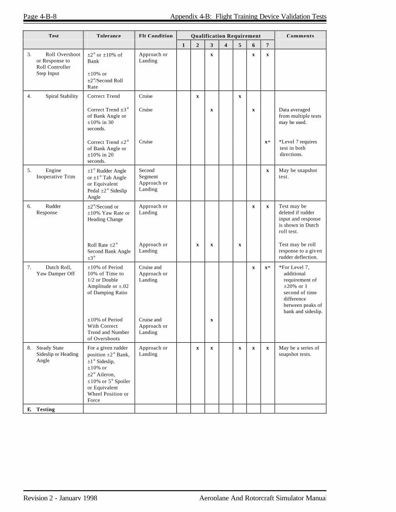
Page 4-B-8 Appendix 4-B: Flight Training Device Validation Tests
Revision 2 - January 1998 Aeroplane And Rotorcraft Simulator Manual
Test Tolerance Flt Condition Qualification Requirement Comments
1 2 3 4 5 6 7
3. Roll Overshoot or Response to Roll Controller Step Input
±2° or ±10% of Bank ±10% or ±2°/Second Roll Rate
Approach or Landing
x x x
4. Spiral Stability Correct Trend Cruise
x x
Correct Trend ±3° of Bank Angle or ±10% in 30 seconds.
Cruise x x Data averaged from multiple tests may be used.
Correct Trend ±2° of Bank Angle or ±10% in 20 seconds.
Cruise x* *Level 7 requires test in both directions.
5. Engine Inoperative Trim
±1° Rudder Angle or ±1° Tab Angle or Equivalent Pedal ±2° Sideslip Angle
Second Segment Approach or Landing
x May be snapshot test.
6. Rudder Response
±2°/Second or ±10% Yaw Rate or Heading Change
Approach or Landing
x x Test may be deleted if rudder input and response is shown in Dutch roll test.
Roll Rate ±2° Second Bank Angle ±3°
Approach or Landing
x x x Test may be roll response to a given rudder deflection.
7. Dutch Roll, Yaw Damper Off
±10% of Period 10% of Time to 1/2 or Double Amplitude or ±.02 of Damping Ratio
Cruise and Approach or Landing
x x* *For Level 7, additional requirement of ±20% or 1 second of time difference between peaks of bank and sideslip.
±10% of Period With Correct Trend and Number of Overshoots
Cruise and Approach or Landing
x
8. Steady State Sideslip or Heading Angle
For a given rudder position ±2° Bank, ±1° Sideslip, ±10% or ±2° Aileron, ±10% or 5° Spoiler or Equivalent Wheel Position or Force
Approach or Landing
x x x x x May be a series of snapshot tests.
E. Testing
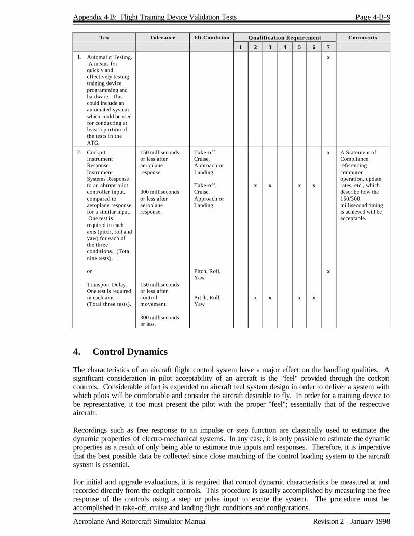
Appendix 4-B: Flight Training Device Validation Tests Page 4-B-9
Aeroplane And Rotorcraft Simulator Manual Revision 2 - January 1998
Test Tolerance Flt Condition Qualification Requirement Comments
1 2 3 4 5 6 7
1. Automatic Testing. A means for quickly and effectively testing training device programming and hardware. This could include an automated system which could be used for conducting at least a portion of the tests in the ATG.
x
2. Cockpit Instrument Response. Instrument Systems Response to an abrupt pilot controller input, compared to aeroplane response for a similar input. One test is required in each axis (pitch, roll and yaw) for each of the three conditions. (Total nine tests).
or Transport Delay.
One test is required in each axis. (Total three tests).
150 milliseconds or less after aeroplane response. 300 milliseconds or less after aeroplane response. 150 milliseconds or less after control movement. 300 milliseconds or less.
Take-off, Cruise, Approach or Landing Take-off, Cruise, Approach or Landing Pitch, Roll, Yaw Pitch, Roll, Yaw
x
x
x
x
x
x
x
x
x
x
A Statement of Compliance referencing computer operation, update rates, etc., which describe how the 150/300 millisecond timing is achieved will be acceptable.
4. Control Dynamics The characteristics of an aircraft flight control system have a major effect on the handling qualities. A significant consideration in pilot acceptability of an aircraft is the "feel" provided through the cockpit controls. Considerable effort is expended on aircraft feel system design in order to deliver a system with which pilots will be comfortable and consider the aircraft desirable to fly. In order for a training device to be representative, it too must present the pilot with the proper "feel"; essentially that of the respective aircraft. Recordings such as free response to an impulse or step function are classically used to estimate the dynamic properties of electro-mechanical systems. In any case, it is only possible to estimate the dynamic properties as a result of only being able to estimate true inputs and responses. Therefore, it is imperative that the best possible data be collected since close matching of the control loading system to the aircraft system is essential. For initial and upgrade evaluations, it is required that control dynamic characteristics be measured at and recorded directly from the cockpit controls. This procedure is usually accomplished by measuring the free response of the controls using a step or pulse input to excite the system. The procedure must be accomplished in take-off, cruise and landing flight conditions and configurations.
Page 4-B-10 Appendix 4-B: Flight Training Device Validation Tests
Revision 2 - January 1998 Aeroplane And Rotorcraft Simulator Manual
For aircraft with irreversible control systems, measurement may be obtained on the ground if proper pitot static inputs are provided to represent airspeeds typical of those encountered in flight. Likewise, it may be shown that for some aircraft, take-off, cruise and landing configurations have like effects. Thus, one may suffice for another. If either or both considerations apply, engineering validation or manufacturer rationale must be submitted as justification for ground tests or for eliminating a configuration. For devices requiring static and dynamic tests at the controls, special test fixtures will not be required during initial and upgrade evaluations if the operator's ATG shows both test fixture results and the results of an alternate approach, such as computer plots which were produced concurrently and show satisfactory agreement. Repeat of the alternate method during the initial evaluation would then satisfy this test requirement.

Appendix 4-B: Flight Training Device Validation Tests Page 4-B-11
Aeroplane And Rotorcraft Simulator Manual Revision 2 - January 1998
5. Control Dynamics Evaluation The dynamic properties of control systems are often stated in terms of frequency, damping and a number of other classical measures which can be found in texts on control systems. In order to establish a consistent means of showing test results for control loading, criteria are needed that will clearly define the interpretation of the measurements and the tolerances to be applied. Criteria are needed for both underdamped and critically and overdamped systems. In case of an underdamped system with very light damping, the system may be quantified in terms of frequency and damping. In critically damped or overdamped systems, the frequency and damping are not readily measured from a response time history. Therefore, some other measurement must be used. Tests to verify that control feel dynamics represent the aircraft must show that the dynamic damping cycles (free response of the controls) match that of the aircraft within 10% of period and 10% of damping. The method of evaluating the response is described below for the underdamped and critically damped cases. Underdamped Responses Two measurements are required for the period: the time to first zero crossing (in case a rate limit is present) and the subsequent frequency of oscillation. It is necessary to measure cycles on an individual basis in case there are non-uniform periods in the response. The damping tolerance should be applied to overshoots on an individual basis. Care should be taken when applying the tolerance to small overshoots since the significance of such overshoots becomes questionable. Only those overshoots larger than 5% of the total initial displacement should be considered significant. The results should show the same number of significant overshoots to within one when compared to the aircraft data. This procedure for evaluating the response is illustrated in Figure 1. Critically Damped and Overdamped Response Due to the nature of critically damped responses (no overshoots), the time to reach 90% of the steady state (neutral point) value should be the same as the aircraft within +10%. The training device response should be critically damped also. Figure 2 illustrates the procedure. Tolerances The following table summaries the tolerances, T. See Figures 1 and 2 for an illustration of the referenced measurements.
T(P0) T(P1) T(Pn) T(An) T(Ad) Overshoots
±10% of P0 ±20% of P1 ±10% of Pn ±10% of An, 20% of Subsequent Peaks ±5% of Ad ±1

Page 4-B-12 Appendix 4-B: Flight Training Device Validation Tests
Revision 2 - January 1998 Aeroplane And Rotorcraft Simulator Manual
Alternate Method for Control Dynamics One aircraft manufacturer asserts that adjusting a control loading system for column releases may introduce an unnecessary error for normal pilot commands away from neutral. Instead of free response measurements, the system would be validated by measurements of column force as a function of hands on column rate. For each axis of pitch, roll and yaw, the control shall be forced to its extreme position at two distinct rates. One that achieves maximum deflection in approximately two seconds and one that achieves maximum deflection in approximately one second. Tolerances on the total force shall be the same as for the static check with the additional requirement that the dynamic increment be in the correct sense relative to the static force level. Where flight configurations influence the feel forces of the controls, these tests shall be conducted at a typical taxi take-off cruise and landing condition. TC is open to alternative means such as the one described above. Such alternatives must, however, be justified and appropriate to the application. For example, the method described here would not likely apply to other manufacturers' systems and certainly not to aircraft with reversible control systems. Hence, each case must be considered on its own merit and on an ad hoc basis. Should TC find that alternative methods do not result in satisfactory simulator performance, then more conventionally accepted methods must be used.
Figure 1 Under-Damped Step Response
T(P0) T(P1)
Ad
T(A1)
P0 P1
T(Ad)
A1
P = PeriodA = AmplitudeT(P) = Tolerance Applied to PeriodT(A) = Tolerance Applied to Amplitude
Displacement Versus Time

Appendix 4-B: Flight Training Device Validation Tests Page 4-B-13
Aeroplane And Rotorcraft Simulator Manual Revision 2 - January 1998
Figure 2 Critically Damped Step Response
Ad
P0
T(P0)
90% of Ad
Displacement Versus Time

Aeroplane And Rotorcraft Simulator Manual Revision 2 - January 1998
Appendix 4-C Functions and Subjective Tests 1. Discussion Accurate replication of aircraft systems functions will be checked at each flight crew member position by a TC Specialist. This includes procedures using the operator's approved manuals and checklists. Handling qualities, performance and systems operation will be subjectively assessed by an appropriately qualified TC inspector. The operator may request that the inspector assess the training devices for a special aspect of an operator's training program during the functions and subjective portion of a recurrent evaluation. For example, such an assessment may include a portion of a LOFT scenario or special emphasis items in the operator's training program, if appropriate. Unless directly related to a requirement for the current qualification level, the results of such an evaluation would not affect the training device's current status. Operational principal navigation systems including inertial navigation systems, OMEGA or other long range systems and the associated electronic display systems will be evaluated if installed. The inspector will include in his/her report the effect of the system operation and system limitations. 2. Test Requirements The ground and flight tests and other checks required for qualification are listed in the Table of Functions and Subjective Tests. The table includes manoeuvres and procedures that are accomplished during the evaluation process to assure that the flight training device functions and performs appropriately. It must be understood that there is no direct correlation between the manoeuvres and procedures in this Appendix and any manoeuvre or procedure that may be authorized for a training or checking. Manoeuvres and procedures are also included to address some features of advanced technology aircraft and innovative training programs. For example, "high angle of attack manoeuvring" is included to provide an alternative to "approach to stalls". Such an alternative is necessary for aircraft employing flight envelope limiting systems. The portion of the table addressing pilot functions and manoeuvres is divided by flight phases. All systems functions will be assessed for normal and, where appropriate, alternate operations. Normal, abnormal and emergency procedures associated with a flight phase will be assessed during the evaluation of manoeuvres or events within that flight phase. Systems are listed separately under "Any Flight Phase" to assure appropriate attention to system checks. The functions and subjective test requirements listed in the table are not applicable in cases in which the training device does not include the system or function to be checked even though it may be indicated by a check mark (x) in the Table. Some tests may be added for rotorcraft FTDs. This is particularly true for Levels 2, 4 and 5 which require as little as one functioning system. When using the tables, one must apply logic to permit the required flexibility for these devices and not demand unintended systems. There are manoeuvres that will be subjectively evaluated under asymmetric thrust conditions. For Level 7, this will be applicable only for those highly augmented aeroplanes in which flight test data verifies the absence of motion without pilot input during the manoeuvre being accomplished. In the absence of this data for Level 7 and for all situations in Levels 2-6, these asymmetric thrust manoeuvres are evaluated here only to verify that the procedures for the specific event may be accomplished satisfactorily. This evaluation does not imply that the manoeuvre itself, or the demonstration of proficiency in the application of the procedures, may be accomplished in any vehicle other than an appropriately qualified simulator or

Page 4-C-2 Appendix 4-C: Functions and Subjective Tests
Revision 2 - January 1998 Aeroplane And Rotorcraft Simulator Manual
the aircraft. 3. Table of Functions and Subjective Tests
FTD Level Comments
1 2 3 4 5 6 7
1. FUNCTIONS AND MANOEUVRES
A. PREPARATION FOR FLIGHT
1. Pre-flight. Accomplish a functions check of all switches, indicators, systems and equipment at all crew members' and instructors' stations and determine that the cockpit or flight deck area design and replicate the appropriate aeroplane.
x x x x x x For Levels 2 and 3, cockpit/flight deck area design and functions must be representative of the appropriate set of aeroplanes.
B. SURFACE OPERATIONS (PRE-TAKE-OFF)
1. Engine Start x* x x* x* x x * If appropriate to installed
(a) Normal Start systems.
(b) Alternate Start Procedures
(c) Abnormal Starts and Shutdowns (hot start, hung start, etc.)
2. Pushback x x* x x
3. Thrust Response x x x x x
4. Power Level Friction x x x x x
5. Brake Operation (normal/alternate/emergency)
x* x x* x x
6. Brake Fade (if applicable) x
7. Other
C. TAKE-OFF
1. Normal
(a) Powerplant Checks (engine parameter relationships)
x* x x* x* x x * If appropriate to installed systems.
(b) Acceleration Characteristics
x* x x* x x
(c) Nosewheel and Rudder Steering
x* x x* x x
(d) Effect of Crosswind
x x x x x
(e) Special Performance
x x x
(f) Instrument
x x x x x
(g) Landing Gear, Wing Flap, Leading Edge Device Operation
x* x x* x x
(h) Other

Appendix 4-C: Functions and Subjective Tests Page 4-C-3
Aeroplane And Rotorcraft Simulator Manual Revision 2 - January 1998
FTD Level Comments
1 2 3 4 5 6 7
2. Abnormal/Emergency
(a) Rejected x x x
(b) Rejected Special Performance
x x x
(c) With Failure of Most Critical Engine at Most Critical Point Along Take-off Path (continued take-off)
x Applicable only to those highly augmented aeroplanes in which test flight data verifies the absence of motion without pilot input during this manoeuvre.
(d) Flight Control System Failure Modes x x x x x x If appropriate to the aeroplane and the installed systems.
(e) Other
D. INFLIGHT OPERATION
1. Climb x x x x x
(a) Normal
(b) One Engine Inoperative Procedures
(c) Other
2. Cruise
(a) Performance Characteristics (speed versus power)
x x x x x
(b) Turns With/Without Spoilers (speed brake) Deployed
x x x x x
(c) High Altitude Handling
x x x x x
(d) High Speed Handling
x x x x x
(e) Mach Effects on Control and Trim, Overspeed Warning
x x x x x If appropriate to the aeroplane or set of aeroplanes.
(f) Normal and Steep Turns
x x x x x
(g) Performance Turns
x x x x x
(h) Approach to Stalls, ie. Stall Warning: No Motion (cruise, take-off/approach and landing configuration)
x x x x x
(i) High Angle of Attack Manoeuvres (cruise, take-off/approach and landing)
x x x x x
(j) Inflight Engine Shutdown
x* x x* x* x x *If appropriate to installed systems.
(k) Inflight Engine Restart
x* x x* x* x x *If appropriate to installed systems.
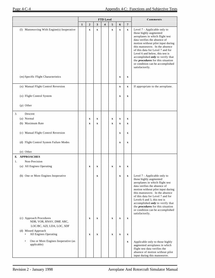
Page 4-C-4 Appendix 4-C: Functions and Subjective Tests
Revision 2 - January 1998 Aeroplane And Rotorcraft Simulator Manual
FTD Level Comments
1 2 3 4 5 6 7
(l) Manoeuvring With Engine(s) Inoperative x x x x x Level 7 - Applicable only to those highly augmented aeroplanes in which flight test data verifies the absence of motion without pilot input during this manoeuvre. In the absence of this data for Level 7 and for Level 6 and below, this test is accomplished only to verify that the procedures for this situation or condition can be accomplished satisfactorily.
(m) Specific Flight Characteristics
x x
(n) Manual Flight Control Reversion
x x If appropriate to the aeroplane.
(o) Flight Control System
x x
(p) Other
3. Descent
(a) Normal x x x x x
(b) Maximum Rate
x x x x x
(c) Manual Flight Control Reversion
x x
(d) Flight Control System Failure Modes
x x
(e) Other
E. APPROACHES
1. Non-Precision
(a) All Engines Operating
x x x x x
(b) One or More Engines Inoperative x x x Level 7 - Applicable only to those highly augmented aeroplanes in which flight test data verifies the absence of motion without pilot input during this manoeuvre. In the absence of this data for Level 7 and for Levels 6 and 3, this test is accomplished only to verify that the procedures for this situation or condition can be accomplished satisfactorily.
(c) Approach Procedures NDB, VOR, RNAV, DME ARC,
LOC/BC, AZI, LDA, LOC, SDF
x x x x x
(d) Missed Approach • All Engines Operating • One or More Engines Inoperative (as
applicable)
x
x
x
x
x
x
Applicable only to those highly augmented aeroplanes in which flight test data verifies the absence of motion without pilot input during this manoeuvre.

Appendix 4-C: Functions and Subjective Tests Page 4-C-5
Aeroplane And Rotorcraft Simulator Manual Revision 2 - January 1998
FTD Level Comments
1 2 3 4 5 6 7
2. Precision
(a) PAR - Normal
x x x As applicable.
(b) ILS • Normal • Category I Published Approach - Manually controlled with and
without flight director to 100 ft. (30m) below published decision height
• Category II Published Approach - With use of auto-coupled,
auto-throttle and auto-land, as applicable
• Category III Published Approach - With electrical power - With 10 Knot tailwind - With 10 Knot crosswind
x* x x* x x As applicable. *Auto-coupled approach procedures. Tests accomplished with maximum tailwind and crosswind authorized if less than 10 knots.
(c) Effects of Crosswind
x x x x x As applicable.
(d) With Engine(s) Inoperative x x x x x Level 7 - Applicable only to those highly augmented aeroplanes in which flight test data verifies the absence of motion without pilot input during this manoeuvre. In the absence of this data for Level 7 and for Level 6 and below, this test is accomplished only to verify that the procedures for this situation or condition can be accomplished satisfactorily.
(f) Missed Approach • Normal • With Engine(s) Inoperative • From Steep Glide Slope
x
x
x
x
x
x
x
x
x
x
x
x
x
x
x
As applicable. See comments for 2.(e) above. As applicable.
F. SURFACE OPERATIONS (POST LANDING)
1. Landing Roll
(a) Spoiler Operation x* x* x* x x * If applicable to installed systems.
(b) Reverse Thrust Operation x x x
(c) Other
H. ANY FLIGHT PHASE
1. Aircraft and Powerplant Systems Operation x x x x x x If applicable to installed systems.
(a) Air Conditioning
(b) Anti-icing/De-icing
(c) Auxiliary Powerplant
(d) Communications
(e) Electrical
(f) Fire Detection and Suppression
(g) Flaps
(h) Flight Controls (including spoilers/speedbrake)
(i) Fuel and Oil
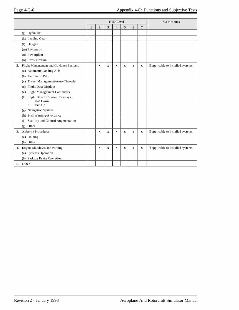
Page 4-C-6 Appendix 4-C: Functions and Subjective Tests
Revision 2 - January 1998 Aeroplane And Rotorcraft Simulator Manual
FTD Level Comments
1 2 3 4 5 6 7
(j) Hydraulic
(k) Landing Gear
(l) Oxygen
(m) Pneumatic
(n) Powerplant
(o) Pressurization
2. Flight Management and Guidance Systems x x x x x x If applicable to installed systems.
(a) Automatic Landing Aids
(b) Automatic Pilot
(c) Thrust Management/Auto-Throttle
(d) Flight Data Displays
(e) Flight Management Computers
(f) Flight Director/System Displays • Head Down • Head Up
(g) Navigation System
(h) Stall Warning/Avoidance
(i) Stability and Control Augmentation
(j) Other
3. Airborne Procedures x x x x x x If applicable to installed systems.
(a) Holding
(b) Other
4. Engine Shutdown and Parking x x x x x x If applicable to installed systems.
(a) Systems Operation
(b) Parking Brake Operation
5. Other

Aeroplane And Rotorcraft Simulator Manual Revision 2 - January 1998
Chapter 5 Simulator Component Inoperative Guide 5.1 Purpose 5.1.1 The CARs state that each aircraft simulator in an approved training and checking program shall
maintain the performance, functional and other characteristics required for approval. This means that each simulator must operate with all components operational at all times. If at any time its performance is degraded for any reason, the approval is void and any training or checking completed on the simulator while it is in this condition is invalid.
5.1.2 Some training and checking could be completed with certain components inoperative if relief
were provided to the simulator approval requirements. While the aircraft Minimum Equipment List (MEL) is an important tool in training, especially in Line Oriented Flight Training (LOFT), it is not a practical relief vehicle. It relates directly to flight safety and airworthiness issues while the real issue is quality of training and not, strictly speaking, flight safety. Therefore, the MEL is not to be used to determine simulator training or checking status and another method of providing relief is required. This relief from the initial simulator approval requirements is permitted through the use of a Simula tor Component Inoperative Guide (SCIG). Preparation and use of an SCIG is mandatory.
5.1.3 Though the SCIG is concerned mainly with relief for full flight simulators, an SCIG can be
prepared, approved and used with a training device. 5.2 Application for Use of the SCIG 5.2.1 The individual operator (the Air Operator Certificate holder, company organization or private
citizen using the simulator), is responsible for a SCIG that reflects their operation/training program. For example, one operator may train and check to Category II/III limits while another may train and check only to Category I limits; therefore, the second operator could use relief from Category II/III related component unserviceabilities.
5.2.2 Once the operator has prepared a SCIG, using the example in this Chapter as a guide, it shall be
submitted to the MSP for approval. The MSP will review it for compliance with this manual and forward it to the operational authority for approval.
5.2.3 When approval is obtained, the SCIG will become part of the operator’s training program. The
SCIG must be readily available for review for each simulator training or checking session. 5.3 Procedures for Using the SCIG 5.3.1 Any component or subpart of a simulator that is intentionally made inoperative for the purpose of
training or checking by inserting a malfunction on the instructor's console is not considered inoperative for the purpose of the SCIG.
Page 5-2 Chapter 5: Simulator Component Inoperative Guide
Revision 2 - January 1998 Aeroplane And Rotorcraft Simulator Manual
5.3.2 Each component that becomes inoperative shall be recorded in the maintenance log book for that simulator and its impact on the approved status of the device is to be determined using the SCIG. Any system or subpart that is not listed in the guide shall be operational at all times when training for credits or checking is being conducted. All components and systems are required to operate for all checking, except as noted under "Remarks" in Appendix 5-A.
5.3.3 There is no time period in which an inoperative component listed in the guide must be repaired;
however, it is to the benefit of the operator to expedite repairs as training and checking are severely restricted.
5.3.4 When a component becomes inoperative and the "Situation" column in Appendix 5-A states "no
training or checking", this means that the training credits and checking authorized for that phase of simulator are not allowed until the component is repaired.
5.4 SCIG Description 5.4.1 An example SCIG is contained in Appendix 5-A of this manual. This is an example for an
aeroplane simulator; however, the same format and related content can be used for rotorcraft simulators and FTDs.
5.4.2 Appendix 5-A lists the major simulator components, the operational condition of the component,
the phase of simulator the component applies to, the category the simulator is placed in because of the component's condition and prescribes the action that is required for training or checking, if authorized.
5.4.3 When a component becomes inoperative the simulator will be placed in one of the following
categories: a) no training or checking; b) training under specific conditions; or c) checking. 5.4.4 An explanation of the column headings from Appendix 5-A is as follows: Component Fa principal essential part such as the radios, performance instruments, engine
instruments, system control panels, motion system, visual system or control loading that is computer operated, including the computer.
Situation F indicates which component or subpart has failed or deteriorated below initial
qualification standards. Level F refers to the approved level of the simulator only and indicates to which level of
simulator the inoperative component applies. Categories F are restrictions or authorizations placed on the simulator when a component
becomes inoperative. Remarks F contains the conditions that must be met for training in specific conditions or when
checking is authorized.
Chapter 5: Simulator Component Inoperative Guide Page 5-3
Aeroplane And Rotorcraft Simulator Manual Revision 2 - January 1998
5.4.5 The following definitions are applicable to Appendix 5-A: No Training or Checking F means that the training credits and checking that were authorized
in that level of simulator are not allowed with the component inoperative. Training in Specific Conditions F means some training is permitted if certain conditions are
met as stated under the "Remarks" column in Appendix 5-A. Checking F means any checking for a flight crew member licence, rating, type rating, LOFT,
recency of experience, night take-off and landings and proficiency checks.

Aeroplane And Rotorcraft Simulator Manual Revision 2 - January 1998
Appendix 5-A Simulator Component Inoperative Guide
Example:
Component Situation Level Categories Remarks
Visual Optical System Captain Forward Cathode Ray Tube (CRT) Inoperative
A,B,C,D Training under Specific Conditions*
First Officer and Flight Engineer Training (only). Instructor may occupy captain or instructor seat. Another pilot may occupy captain's seat but receives no credit. * Flight Engineer checking authorized.
Captain Side CRT Inoperative **
C,D Training under Specific Conditions*
** If Level C or D training program: First Officer and Flight Engineer Training (only). Instructor may occupy captain or instructor seat. Another pilot may occupy captain's seat but receives no credit. **If Level A or B training program: No left circling procedures. * Flight Engineer checking authorized.
Captain Side CRT Inoperative ***
A,B Training under Specific Conditions*
*** If fitted. No left circling procedures. * All checking authorized except for left circling procedures.
First Officer Forward CRT Inoperative
A,B,C,D Training under Specific Conditions*
Captain and Flight Engineer Training (only). Instructor may occupy First Officer or instructor seat. Another pilot may occupy First Officer's seat but receives no credit. * Flight Engineer checking authorized.
First Officer Side CRT Inoperative**
C,D Training under Specific Conditions*
** If Level C or D training program: Captain and Flight Engineer Training (only). Instructor may occupy First Officer or instructor seat. Another pilot may occupy First Officer's seat but receives no credit. **If Level A or B training program: No right circling procedures. * Flight Engineer checking authorized.
First Officer Side CRT Inoperative***
A,B Training under Specific Conditions*
*** If fitted. No right circling procedures. * All checking authorized except for right circling procedures.
Daylight scene not available
D Training under Specific Conditions
All training and checking using dusk, dawn and/or night scenes permitted.

Page 5-A-2 Appendix 5-A: Simulator Component Inoperative Guide - Example
Revision 2 - January 1998 Aeroplane And Rotorcraft Simulator Manual
Component Situation Level Categories Remarks
Visual Optical System Wide 150° Overhead Projector Facing the Visual from the Pilot Seats are Numbered Left to Right #1, #2, #3
#1 Overhead Projector Inoperative #2 Overhead Projector Inoperative #3 Overhead Projector Inoperative #1, #2 and #3 Overhead Projectors Inoperative
A,B,C,D A,B,C,D A,B,C,D A,B,C,D
Training under Specific Conditions* No Training or Checking* Training under Specific Conditions* No Training or Checking*
Captain and Flight Engineer Training (only). Instructor may occupy captain or instructor seat. Another pilot may occupy first officer seat but receives no credit. * Flight Engineer checking authorized. * Flight Engineer checking authorized. First Officer and Flight Engineer Training (only). Instructor may occupy captain or instructor seat. Another pilot may occupy captain seat but receives no credit. * Flight Engineer checking authorized. * Flight Engineer checking authorized.
Motion System Inoperative A,B,C,D No Training or Checking*
* Flight Engineer checking authorized.
Control Loading System Inoperative A,B,C,D No Training or Checking
N/A
Sound Audio System Inoperative A,B,C,D Training under Specific Conditions
Must be operational and at the volume level as initially approved for all training and checking; however, an instructor may turn the sound completely off for short durations to instruct or explain procedures.
Console at Instructor Station
Inoperative A,B,C,D Training under Specific Conditions
May be inoperative if a portable remote control unit is available and operational. The instructor may use the unit from any seat location.
Lights and Annunciator including Master Warning
Inoperative A,B,C,D Training under Specific Conditions
Malfunction Illuminated. One annunciator light on each system may be inoperative provided the same information can be obtained from another source. Example: Oil pressure warning light inoperative, oil pressure instrument gauge could be used. Normal Operation Illuminated. Lights may be inoperative provided required information can be obtained from another source. Example: Pilot heat normal operation light is inoperative. Information could be obtained from ammeter.
Light Annunciator Including Master Warning
Inoperative A,B,C,D Training under Specific Conditions
Master Warning. At least one must operate.
Lights Cockpit Controlled Inoperative A,B,C,D Training under Specific Conditions
Any one or group of lights may be inoperative provided lighting is available from another source. Example: The captain's instrument lights are inoperative. The panel fluorescent lights could be used.

Appendix 5-A: Simulator Component Inoperative Guide - Example Page 5-A-3
Aeroplane And Rotorcraft Simulator Manual Revision 2 - January 1998
Component Situation Level Categories Remarks
Instrument Flight One or All are Inoperative
A,B,C,D Training under Specific Conditions
All instruments required by Regulations for the type operation/training to be conducted must operate at the pilot seat where training credit is allowed. Example: Day, night, IFR, VFR. One or all may be inoperative at the other pilot seat. The instructor or another pilot may occupy that seat and no training credit will be allowed.
Instruments Performance Inoperative A,B,C,D Training under Specific Conditions
One per engine may be inoperative. Example: N2 gauge is inoperative. N1, N3, EPR must operate. EGT gauge is required for all training. Torque meter is required for all training. Torque meter is required for all training in turboprop aeroplane simulators.
Instruments Navigation Inoperative A,B,C,D Training under Specific Conditions*
Only those navigation instruments required for the navigation or instrument approach training to be conducted must operate. Example: Conducting NDB approaches, VOR and ILS could be inoperative. * Flight Engineer Training and checking is
authorized.
Instruments Quantity Inoperative A,B,C,D Training under Specific Conditions
One from each system may be inoperative provided the information can be obtained from another source. Example: One fuel tank quantity gauge is inoperative. In the case of quantity, the instructor may provide that information from the instructor's console.
Instruments System Operation
Inoperative A,B,C,D Training under Specific Conditions
One may be inoperative from each system provided system operation can be confirmed from another source. Example: Hydraulic system pressure gauge is inoperative; however, the pressure light operates.
Computer Inoperative A,B,C,D No Training or Checking
N/A
Cockpit to Computer Input-Output System (Signal Conversion)
Inoperative A,B,C,D No Training or Checking
N/A
Aeroplane And Rotorcraft Simulator Manual Revision 2 - January 1998
Chapter 6 Simulator Approval Representative 6.1 Applicability 6.1.1 A Simulator Approval Representative (SAR) is appointed by the Minister to conduct specific
duties on his/her behalf with respect to aircraft simulators and FTDs. The qualifications, privileges and responsibilities of SARs and the responsibilities of their employer are described in this Chapter.
6.1.2 The specific duties shall consist of: a) approving reports relating to the testing, operation and maintenance of aircraft simulators
and training devices; b) conducting device tests and approving device test data; and c) certifying that technical information or data relating to the device design or changes to the
approved design comply with the standards applicable to that device. 6.2 Qualifications for SAR Appointment 6.2.1 An organization which requests the appointment of a SAR shall have a capable simulator
technical organization which is satisfactory to TC. 6.2.2 The individual for whom the SAR appointment is requested shall: a) be a Canadian citizen or a permanent resident within the meaning of the Immigration Act,
1976; b) be engaged in the provision of technical services in an organization that maintains or
operates aircraft simula tors in Canada; c) have a thorough working knowledge of simulators and be technically competent to
effectively apply the aircraft simulator and training device approval standards within the limits of his/her mandate;
d) have the necessary authority in the organization to effectively control the application of
simulator approval and training device standards within the limits of his/her mandate; e) have a satisfactory working relationship with relevant TC staff; f) be personally suitable by exhibiting such characteristics as professional integrity, co-
operative attitude, ability to exercise sound judgement and maintain a high degree of objectivity while performing SAR functions notwithstanding any influence to the contrary;
Page 6-2 Chapter 6: Simulator Approval Representative
Revision 2 - January 1998 Aeroplane And Rotorcraft Simulator Manual
g) be a graduate of a technical college in an appropriate discipline or the equivalent such as completion of an apprentice program; and
h) have at least fifteen years of progressively responsible simulator related technical
experience appropriate to the responsibilities and duties of a SAR. 6.3 Application for Appointment 6.3.1 A senior manager of an organization may nominate a candidate who is employed by the
organization for appointment as a SAR. The application shall include: a) the name of the individual and the address of his/her normal place of business; b) evidence of citizenship or residency status; c) a resume of the candidate's history and current areas of expertise; d) evidence of the academic qualifications and experience of the individual; e) a statement by the candidate agreeing to accept the appointment; and f) a statement by senior management of the organization to — 1. provide the SAR with adequate resources for effective performance of his/her duties, 2. grant the SAR the necessary authority to permit effective application of simulator and
training device standards and procedures as described in this Manual, and 3. support decisions of the SAR in conducting his/her regulatory functions. 6.4 Approval of Appointment 6.4.1 The TC Director, Commercial and Business Aviation or his/her authorized representative shall
interview applicants for a SAR appointment to determine the adequacy of their knowledge of regulations and procedures with respect to aircraft simulator and training device evaluations.
6.4.2 If an applicant is found to be acceptable, TC will issue a Certificate of Appointment. 6.5 Validity of Appointment 6.5.1 Unless terminated under Section 6.5.2 of this Chapter, a SAR appointment shall be effective for
up to five years from date of issue. It may be reviewed for additional periods of five years at the discretion of TC. A renewal is effected by issuing a new Certificate of Appointment specifying the renewal period.

Chapter 6: Simulator Approval Representative Page 6-3
Aeroplane And Rotorcraft Simulator Manual Revision 2 - January 1998
6.5.2 A SAR appointment made under this Chapter terminates: a) upon the written request of the SAR; b) upon written request of an employer who nominated the SAR; c) when the SAR ceases employment with the employer who nominated the SAR for
appointment; d) upon a finding by TC that the SAR has not properly performed the duties of a SAR; and e) when a SAR has not exercised the privileges of his appointment for a period in excess of
three years. 6.6 Privileges of a SAR 6.6.1 When he/she determines that changes and tests comply with the standards applicable to an
aircraft simulator or training device the SAR may approve: a) changes to simulator or training device software and hardware; b) changes to the QTG; c) tests to show compliance with standards; and d) other technical changes affecting simulator approval. 6.7 Responsibilities of a SAR 6.7.1 Each SAR shall: a) determine that the information approved or recommended for approval by him/her — 1. complies with pertinent applicable simulator or training device approval standards,
policies and procedures, and 2. has been examined and found to be satisfactory with respect to the use of established
analytical methods, test methods, validity of assumptions and accuracy of calculations; b) provide TC with copies of all documents with respect to matters approved by him/her; c) coordinate with TC the conduct and witnessing of test programs required to demonstrate
compliance with simulator or training device approval standards; and d) attend meetings with TC officials as required.

Page 6-4 Chapter 6: Simulator Approval Representative
Revision 2 - January 1998 Aeroplane And Rotorcraft Simulator Manual
6.8 Responsibilities of the Employer 6.8.1 Each organization that employs a SAR shall: a) make available to the SAR current regulations, advisories and related documents applicable
to his/her function; b) maintain records of all simulator and training device information recommended or approved
by the SAR; c) make available to TC, when requested, the records prescribed in subsection (b) of this
section; d) permit the SAR to attend meetings requested by TC; and e) maintain a simulator and training device technical organization with sufficient resources to
assure a high standard of simulator maintenance and compliance with applicable standards. 6.9 Retention of Records 6.9.1 When a SAR or an organization which employs a SAR no longer utilizes the records of an
approved simulator or training device they must request instructions from TC with respect to the retention or disposition of the records.
6.10 SAR Guidelines 6.10.1 To provide direction to SARs in the conduct of their duties, a set of SAR guidelines is contained
in Appendix 6-A. 6.10.2 The "Simulator Evaluation Report" form appropriate to the approval level and qualification
standards shall be used to document aircraft simulator or training device evaluations.
Aeroplane And Rotorcraft Simulator Manual Revision 2 - January 1998
Appendix 6-A SAR Representative Guidelines 1. Objective of the SAR System To enable an efficient and effective means of ensuring continuing in-service compliance of flight simulators and training devices with applicable TC standards. 2. SAR Definition A SAR is a person authorized by TC to exercise regulatory responsibility with respect to the approval of simulators, FTDs and associated data. 3. Principles of Delegation When a SAR approves any part of a simulator or training device on behalf of TC, he/she shall ensure that the approval is based on compliance with regulatory standards. 4. SAR Authority SARs may be authorized to approve on behalf of TC all or part of the following: a) recurrent evaluations of approved flight simulators or training devices; b) software changes to an approved design; c) hardware changes to an approved design; and d) Qualification Test Guide (QTG) changes. 5. SAR Responsibilities A SAR is responsible for: a) making assessments of compliance with standards and approving or disproving specific simulators,
training devices and associated data; b) documenting the assessments and approvals; and c) providing required data and information to TC.

Page 6-A-2 Appendix 6-A: SAR Representative Guidelines
Revision 2 - January 1998 Aeroplane And Rotorcraft Simulator Manual
6. Procedures Test Program A SAR is responsible for: a) identifying the standards and criteria applicable to each specific approval task (e.g. recurrent evaluation, hardware or software changes); b) performance (quantitative) and functional (subjective) tests being identified to permit an assessment
of compliance with requirements; c) the TC "Simulator Evaluation Report" form being used to help identify tests and assess compliance; d) functional tests being carried out or monitored by a qualified flight crew member and supporting
evidence of compliance or non-compliance being provided by the flight crew member to the SAR; and
e) all performance and functional tests being carried out or supervised by the SAR, e.g., the SAR shall
be present on the test site for all testing. Assessment For each test, the SAR shall make an assessment on the compliance with applicable standards and criteria. Recurrent Evaluations a) Test data results for recurrent evaluations shall be documented on the Simulator Evaluation Report
form. b) Deficiencies or items of non-compliance shall be documented on the Simulator Evaluation Report
form in one of the following priority categories: 1) before next flight; 2) within 15 days; 3) within 30 days; or 4) before next check. c) The decision on priority category shall be based on the impact of the item or issue on the training and
checking role of the simulator or training device. d) Resolution of deficiencies shall be recorded on the Simulator Evaluation Report form with applicable
dates and a SAR stamp to indicate resolution of the problem. e) The Simulator Evaluation Report form shall be retained as a record of the results of each recurrent
evaluation for at least three years. f) The Simulator Evaluation Report shall be used as the approval control document and shall be
maintained in a current state so that the status of the simulator or training device can be readily determined with respect to recurrent evaluations.
g) When a simulator or training device approval is withdrawn, the SAR shall notify TC prior to notifying the holder of the Certificate of Approval for that simulator or training device.
h) When a recurrent evaluation is completed, copies of the cover and deficiency pages of the Simulator

Appendix 6-A: SAR Representative Guidelines Page 6-A-3
Aeroplane And Rotorcraft Simulator Manual Revision 2 - January 1998
Evaluation Report shall be sent to the MSP. 7. Software and Hardware Changes General a) Software and hardware changes may be carried out to: 1) rectify errors; 2) improve characteristics; and 3) respond to regulatory requirements. b) Whenever a change is made, the SAR shall consider all affected performance and functional
standards and criteria in order to make an assessment of the compliance with these standards. The SAR shall develop and conduct appropriate functional tests which will ensure that the change only affected simulator or training device performance in the predicted areas.
Major Software and Hardware Changes a) Where a software change is such that a SAR believes his/her knowledge of all aspects is insufficient
to make an informed decision he/she shall consult with TC. b) Software and hardware changes shall be assessed against every performance and functional
requirement to determine compliance. Much of the judgement and knowledge required is in deciding which tests were affected. A SAR shall not hesitate to consult with the MSP if in doubt as to what is affected by a particular change.
Documentation Software and hardware changes shall be approved by the SAR using the Simulator Evaluation Report form by completing and signing the "Statement of Compliance" on the cover page. 8. Qualification Test Guide (QTG) a) Qualification Test Guides shall be amended to correct errors, improve test methods and data or to
respond to changes in regulations. b) QTG changes shall only be approved by a SAR if the affected tests show compliance with regulatory
standards and criteria. 9. Scheduling Recurrent Evaluations Prior to the start of each approval year, the TC and the SAR will schedule the recurrent evaluations for each simulator for the coming year. 10. SAR Monitoring Program TC will monitor the standards of all approved SARs by: a) observing each SAR conduct a recurrent evaluation once a year; b) reviewing the Air Operator's utilization of the SAR on a periodic basis;

Page 6-A-4 Appendix 6-A: SAR Representative Guidelines
Revision 2 - January 1998 Aeroplane And Rotorcraft Simulator Manual
c) monitoring the activities of each SAR to ensure: 1. the reports are complete, accurate and meaningful, 2. the evaluations cover the required items of the performance and functional areas, 3. the conduct of evaluations is fair and in conformance with the standards and procedures
described in this manual, and 4. the SAR is acting within the limits of the delegated authority. "Monitoring" means taking a passive role in the evaluation. The duties of conducting the evaluation will be the responsibility of the SAR. The Inspector's interest will be in the manner in which the SAR conducts the evaluation, assesses the results and processes the necessary documentation.

Aeroplane And Rotorcraft Simulator Manual Revision 2 - January 1998
Chapter 7 Use of Foreign Simulators and Training Devices An air operator seeking to use a foreign based simulator or training device in an approved training, checking or licensing program must have that simulator or training device certified by TC. To be certified, the simulator or training device must be evaluated and approved in accordance with the same procedures ,as outlined in this Manual, used for domestic simulators or training devices. Furthermore, except for relief as provided in the approved Simulator Component Inoperative Guide (SCIG), the simulator or training device, once certified, must be maintained at the certificated performance level to retain its certification.

Aeroplane And Rotorcraft Simulator Manual Revision 2 - January 1998
Chapter 8 Training and Checking Credits 8.1 Purpose 8.1.1 This Chapter outlines the training and checking credits that may be applied to a simulator or FTD
pursuant to the Canadian Aviation Regulations. 8.2.2 Training and checking credits are based on the certified level of the simulator or FTD as
determined by the MSP in accordance with this Manual. For aeroplanes, these training and checking credits are based on the FAR 121 Appendix H, Advanced Simulation Plan.
8.2 Application of Credits 8.2.1 Once a simulator or FTD has been certified by the MSP, training and checking programs can be
based on this qualification and used as long as the certified performance level is maintained or the device is operated under relief provided in the approved Simulator Component Inoperative Guide (SCIG).
8.2.2 Appendices 8-B to 8-E detail the training and checking credits for aeroplanes and rotorcraft for
each training and checking level or manoeuvre.

Aeroplane And Rotorcraft Simulator Manual Revision 2 - January 1998
Appendix 8-A Flight Training Credits - Aeroplanes 1. Discussion This Appendix describes the training credits that may be granted to an aeroplane simulator or training device pursuant to the Canadian Aviation Regulations. Column I of the table outlines the flight phase or manoeuvre, and Column II outlines the minimum standard or simulator required to conduct the Column I activity. Where neither a simulator nor the aircraft is designated, the flight phase or manoeuvre can be trained and checked in a flight training device (FTD). Since the level of FTD is not always an adequate indicator of what performance is required for credit for each manoeuvre or flight phase, credit will be determined on a case-by-case basis. It can be assumed, however, that a Level 6 or 7 FTD can gain credit for all items not specifically annotated to a full flight simulator or the aircraft. Simulators or training devices may be used in the aeroplane's approved training and checking program; however, each one used in the program must be specifically approved for the certificate holder and by aeroplane type and, if applicable, the particular aeroplane type variant being used by the certificate holder. The simulator must be essentially identical to the certificate holder's aeroplane for it to be used in a program. Simulators depicting EFIS equipped digital aircraft can change the various EFIS presentations relatively easily and inexpensively with software changes. This convertibility of a modern simulator should be considered when approving a specific simulator in a specific training program. In some cases, differences between the simulator and the certificate holder's aeroplane can be addressed by additional ground or aeroplane differences training. Where the TC approved training program permits type endorsement of pilots not current on a similar type aeroplane without any aeroplane training, a Level D simulator must be used for the type endorsement training. For flight engineers or second officers, some aircraft training is always required. Programs that are approved for a specific certificate holder using advanced simulators, e.g. Level C simulators, must be conducted entirely in the approved simulator to gain the credits granted that level of simulator. 2. Flight Training Credits - Aeroplanes Note: A “x” in COLUMN II indicates the minimum standard simulator to conduct the COLUMN I
activity. A “x” in the AEROPLANE column means that only the aeroplane operator's aircraft can be used.
COLUMN I COLUMN II AEROPLANE
SIMULATOR LEVEL
A B C D
1. Pre-flight a. A visual inspection of the exterior and interior of the aeroplane.
x
b. The proper use of the pre-start check list, appropriate control system checks, starting procedures, checks of all radio and electronic equipment and the selection of the proper navigation and communication radio frequencies and facilities prior to flight.

Page 8-A-2 Appendix 8-A: Flight Training Credits - Aeroplanes
Revision 2 - January 1998 Aeroplane And Rotorcraft Simulator Manual
COLUMN I COLUMN II AEROPLANE
SIMULATOR LEVEL
A B C D
c. Taxiing, sailing or docking procedures, where appropriate. x
d. Pre-takeoff checks and power/plant checks.
2. Takeoff a. Normal takeoff.
x
b. Instrument takeoff. x
c. Crosswind takeoff. x
d. Simulated critical engine failure during takeoff, where failure of the critical engine occurs at a point after V1 speed.
x1 x
e. Rejected takeoff performed prior to V1 speed. x1 x1
x
3. Inflight (where appropriate to the aeroplane type) a. Dutch rolls.
x
b. Turns with and without spoilers. x
c. Tuck tendency and Mach buffets. x
d. Operation of systems and controls at the flight engineer station.
e. Procedures for runaway or jammed stabilizer. x
f. Normal, abnormal or alternate operations of the following systems, devices and aids —
(1) pressurization; (2) pneumatic; (3) air conditioning; (4) fuel and oil; (5) electrical; (6) hydraulic; (7) flight controls; (8) anti-icing and de-icing; (9) automatic and other approach aids; (10) stall warning and avoidance devices and stability augmentation
devices; (11) airborne radar devices; and (12) any other systems, devices or aids available.
x
x
g. In flight emergency procedures for — (1) powerplant, heater, cargo compartment, cabin, flight deck, wing
and electrical fires; (2) smoke control and removal; (3) decompression and rapid decompression; (4) powerplant failure; (5) fuel dumping; (6) emergency descent; (7) any other emergency procedures outlined/in the aircraft flight
manual; (8) flight control; (9) electrical, hydraulic, and flight instrument system malfunction or
failure; (10) landing gear and flap system failures or malfunctions; (11) failure of navigation equipment; and (12) failure of communications equipment.
2
x2
2
2
1 Permitted, provided the simulator has the "engine-out" data package installed.
2 Level C required if the failure or malfunction would change the normal/flight characteristics of the aeroplane during any phase of flight.

Appendix 8-A: Flight Training Credits - Aeroplanes Page 8-A-3
Aeroplane And Rotorcraft Simulator Manual Revision 2 - January 1998
COLUMN I COLUMN II AEROPLANE
SIMULATOR LEVEL
A B C D
h. Steep turns involving bank angle of 45° and a change in heading of at least 180°.
x
i. Approaches to stall under instrument flight rules, including stalls in — (1) takeoff configuration; (2) clean configuration; and (3) landing configuration.
x x x
j. An approach to one stall performed in a turn with a bank angle of between 15° and 30° with a stall warning device inoperative.
x
k. Recovery from specific flight characteristics that are peculiar to the aeroplane type.
x2
l. Engine shutdown and restart.
m. Instrument procedures, including — (1) area departure and arrival; (2) use of navigation systems including adherence to assigned radials
and tracks; (3) holding; (4) Category II approaches; and (5) Category III approaches.
n. Windshear. x3
o. TCAS. 4
4. Landing and Approach to Landing a. Precision approaches, including, as applicable, ILS, MLS and PAR
approaches.
b. Non-precision approaches.
c. Circling approaches. x5 x5
x5 x5
d. Autopilot coupled approaches.
e. Approaches with malfunctioning flaps, slats or both. x
f. (1) Missed approach procedures where the missed approach procedures are conducted with a critical engine failure or other systems failure that could affect that procedure:
(i) from precision approaches; and (ii) from non-precision approaches. (2) Missed approach procedures with all engines and, other systems
that failures of which could affect that procedure, operating normally:
(i) from precision approaches; and (ii) from non-precision approaches.
x1
g. Normal landings which shall, where practicable, be conducted without external or internal glideslope information.
x
h. Landings from precision approaches. x
i. Crosswind landings. x
j. Landings with failures of 50% of the available engines — (1) on a four engine aeroplane, on one side; and (2) on a three engine aeroplane, the failure of the critical outboard
engine and centreline engine is simulated.
x x
3 Authorized, provided the simulator has a "windshear" data package installed.

Page 8-A-4 Appendix 8-A: Flight Training Credits - Aeroplanes
Revision 2 - January 1998 Aeroplane And Rotorcraft Simulator Manual
COLUMN I COLUMN II AEROPLANE
SIMULATOR LEVEL
A B C D
k. Landings from a circling approach. x5
l. Rejected landings. x
m. Landings with malfunctioning flaps or slats or both. x
n. Manual reversion landings. x
o. Landings and go around with the horizontal stabilizer out of trim. x
p. Landings at night. x
q. Auto land: (1) normal, and (2) abnormal.
x
5. Ground Handling Manoeuvres and Procedures a. Emergency procedures including wheel, brake, engine and cabin fires,
loss of nosewheel steering and brake failure.
x
b. Manoeuvring in apron areas. x

Aeroplane And Rotorcraft Simulator Manual Revision 2 - January 1998
Appendix 8-B Proficiency Check Credits - Aeroplanes 1. Discussion This Appendix describes the checking credits that may be granted to an aeroplane simulator or FTD pursuant to the CARs. Column I of the table outlines the flight phase or manoeuvre, and Column II outlines the minimum standard of simulator required to conduct the Column I activity. Checking credits granted to a simulator pursuant to the CARs may be more restrictive than the training credits granted the same device, depending on the configuration and performance of the device. Where neither a simulator nor the aircraft is designated, the flight phase or manoeuvre can be trained and checked in a flight training device. Since the level of training device is not always an adequate indicator of what performance is required for credit for each manoeuvre or flight phase, credit will be determined on a case-by-case basis. It can be assumed, however, that a Level 6 or 7 training device can gain credit for all items not specifically annotated to a full flight simulator or the aircraft. 2. Proficiency Check Credits - Aeroplanes Note: A “x” in COLUMN II indicates the minimum standard simulator to conduct the COLUMN I
activity. A “x” in the AEROPLANE column means that only the aeroplane operator's aircraft can be used.
COLUMN I COLUMN II AEROPLANE
SIMULATOR LEVEL
A B C D
1. Pre-flight
a. Taxiing: (1) taxiing procedures including where appropriate, sailing and
docking procedures, and (2) taxiing check including — - the use of the taxiing check list, and - taxiing.
x
x
b. Engine checks.
2. Takeoff
a. Normal Takeoff. x
b. Noise Abatement Takeoff. x
c. Instrument Takeoff. x
d. Crosswind. x
e. A simulated engine failure takeoff where the simulated failure of the critical engine shall occur at a point after V1 and before V2.
x1 x2
x
1 Permitted, provided the simulator has the engine-out data package installed.
2 Authorized, provided the simulator has an adequate field of view and is specifically approved for circling approaches.

Page 8-B-2 Appendix 8-B: Proficiency Check Credits - Aeroplanes
Revision 2 - January 1998 Aeroplane And Rotorcraft Simulator Manual
COLUMN I COLUMN II AEROPLANE
SIMULATOR LEVEL
A B C D
f. A rejected takeoff prior to V1 x1 x1
x
3. Instrument Procedures a. Arrival area and an area departure procedure;
b. Holding procedure;
c. Instrument approaches;
d. Circling approach; x2 x2
x2 x2
e. Missed approach (normal);
f. Missed approach (engine failure); x1 x1
x
g. Category II approaches; and
h. Category II approaches.
4. In Flight Items a. With a stall warning device inoperative: • a steep turn in each direction with a bank angle of 45
0 and a
change in heading of at least 1800, and
• approaches to the stall: - in the takeoff configuration, and - in a clean configuration; and
x
x x
b. Simulated engine failure(s) x1 x1
x
5. LANDINGS AND APPROACHES TO LANDINGS a. Normal landings without external or internal glideslope information
x
b. Landing from a precision approach x
c. Landing from a circling approach x2
d. Rejected landing x
6. Normal and Abnormal Procedures a. Anti-icing and de-icing systems.
b. Autopilot systems.
c. Automatic or other approach aid systems.
d. Stall warning devices, stall avoidance devices and stability augmentation devices.
x
e. Airborne radar devices. x
f. Other systems, devices or aids. x3
g. Windshear. x4
h. TCAS. x5
3 Authorized, provided the simulator has "windshear" data package installed.
4 Authorized, provided the simulator has "TCAS" data package installed.

Aeroplane And Rotorcraft Simulator Manual Revision 2 - January 1998
Appendix 8-C Flight Engineer/Second Officer Proficiency Check Credits - Aeroplanes 1. Discussion This Appendix describes the checking credits that may be granted to an aeroplane simulator pursuant to the CARs. Column I of the table outlines the flight phase or manoeuvre, and Column II outlines the minimum standard of simulator required to conduct the Column I activity. Checking credits granted to a simulator pursuant to the CARs may be more restrictive than the training credits granted the same device, depending on the configuration and performance of the device. Where neither a simulator nor the aircraft is designated, the flight phase or manoeuvre can be trained and checked in a flight training device. Since the level of training device is not always an adequate indicator of what performance is required for credit for each manoeuvre or flight phase, credit will be determined on a case-by-case basis. It can be assumed, however, that a Level 6 or 7 training device can gain credit for all items not specifically annotated to a full flight simulator or the aircraft. 2. Flight Engineer/Second Officer Proficiency Check Credits - Aeroplanes Note: A “x” in COLUMN II indicates the minimum standard simulator to conduct the COLUMN I
activity. A “x” in the AEROPLANE column means that only the operator's aircraft can be used. Each specific Level 6 or 7 FTD must be specifically approved for the individual carrier for these check credits.
COLUMN I FTD
Level COLUMN II AEROPLANE
SIMULATOR LEVEL
A B C D
1. Pre-flight
a. Aeroplane inspection (1) visual inspection of the exterior and interior of the
aeroplane; (2) fuelling procedures; (3) the use of the pre-start, start and pre-taxi checklists;
and (4) load control and cargo securing.
6/7 6/7 6/7
x
b. Taxiing - use of checklist. 6/7
2. Inflight
a. Procedures and checklist use. 6/7
3. After Flight
a. Procedures and checklist use. 6/7
Note: Each specific Level 6 or 7 FTD must be specifically approved for the individual operator for these check credits.
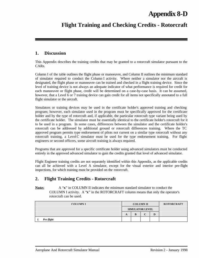
Aeroplane And Rotorcraft Simulator Manual Revision 2 - January 1998
Appendix 8-D Flight Training and Checking Credits - Rotorcraft 1. Discussion This Appendix describes the training credits that may be granted to a rotorcraft simulator pursuant to the CARs. Column I of the table outlines the flight phase or manoeuvre, and Column II outlines the minimum standard of simulator required to conduct the Column I activity. Where neither a simulator nor the aircraft is designated, the flight phase or manoeuvre can be trained and checked in a flight training device. Since the level of training device is not always an adequate indicator of what performance is required for credit for each manoeuvre or flight phase, credit will be determined on a case-by-case basis. It can be assumed, however, that a Level 6 or 7 training device can gain credit for all items not specifically annotated to a full flight simulator or the aircraft. Simulators or training devices may be used in the certificate holder's approved training and checking program; however, each simulator used in the program must be specifically approved for the certificate holder and by the type of rotorcraft and, if applicable, the particular rotorcraft type variant being used by the certificate holder. The simulator must be essentially identical to the certificate holder's rotorcraft for it to be used in a program. In some cases, differences between the simulator and the certificate holder's rotorcraft can be addressed by additional ground or rotorcraft differences training. Where the TC approved program permits type endorsement of pilots not current on a similar type rotorcraft without any rotorcraft training, a Level C simulator must be used for the type endorsement training. For flight engineers or second officers, some aircraft training is always required. Programs that are approved for a specific certificate holder using advanced simulators must be conducted entirely in the approved advanced simulator to gain the credits granted that level of advanced simulator. Flight Engineer training credits are not separately identified within this Appendix, as the applicable credits can all be achieved with a Level A simulator, except for the visual exterior and interior pre-flight inspections, for which training must be provided on the rotorcraft. 2. Flight Training Credits - Rotorcraft Note: A “x” in COLUMN II indicates the minimum standard simulator to conduct the
COLUMN I activity. A “x” in the ROTORCRAFT column means that only the operator's rotorcraft can be used.
COLUMN I COLUMN II ROTORCRAFT
SIMULATOR LEVEL
A B C D
1. Pre-flight

Page 8-D-2 Appendix 8-D: Flight Training and Checking Credits - Rotorcraft
Revision 2 - January 1998 Aeroplane And Rotorcraft Simulator Manual
COLUMN I COLUMN II ROTORCRAFT
SIMULATOR LEVEL
A B C D
a. Aircraft inspection (1) the pre-flight inspection, including — - visual inspection of the exterior and interior of the
aircraft, - pre-start, start and pre-takeoff check procedures, and - communications, navigation systems and instrument
checks.
x x
x
2. Inflight
a. Taxi and hover manoeuvres in ground effect. x
b. Departures, approaches and landings: (1) transition from hover to forward flight and a rejected
departure procedure; (2) transition from hover to forward flight and climb to assigned
altitude; (3) level surface landing; (4) slope surface landing: (5) out of wind approach to hover and landing; (6) autorotation; (7) steep approach; and (8) run-on landing
x
x
x
x x x x
c. Inflight: (1) turns to left and right through at least 180° change of direction
using a bank angle of not less than 30° while maintaining assigned altitude and airspeed;
(2) simulated engine failure at assigned altitude with subsequent autorotational approach for single-engine rotorcraft; and
(3) simulated engine failure and subsequent one engine inoperative approach and landing for multi-engine rotorcraft.
x
x
x
d. Instrument: (1) instrument departure; (2) area departure and area arrival; (3) holding; (4) instrument approaches to hover or touch down — - straight in, and - circling; and (5) instrument approaches to run-on landing — - straight in, and - circling; and (6) missed approach with engine failure;
x x1
x x1
x1
e. Emergency and malfunction procedures: (1) emergency and malfunction procedures, including — - fire in flight, - smoke control, - anti-torque system malfunction or failure, - hydraulic and electrical system malfunctions and failures, - stability augmentation system failures and malfunctions, - gear box failures and malfunctions, and - failure of navigation or communication equipment; and (2) any other emergency procedures outlined in the approved
aircraft flight manual or aircraft operating manual.
x x
x x x2
x x x
1 Authorized provided the simulator has an adequate field of view and is specifically qualified for circling
approaches.
2 To be determined on a per system basis.

Appendix 8-D: Flight Training and Checking Credits - Rotorcraft Page 8-D-3
Aeroplane And Rotorcraft Simulator Manual Revision 2 - January 1998
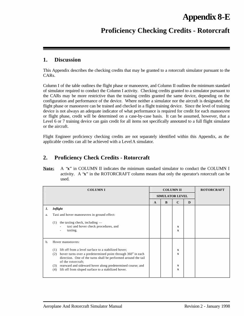
Aeroplane And Rotorcraft Simulator Manual Revision 2 - January 1998
Appendix 8-E Proficiency Checking Credits - Rotorcraft 1. Discussion This Appendix describes the checking credits that may be granted to a rotorcraft simulator pursuant to the CARs. Column I of the table outlines the flight phase or manoeuvre, and Column II outlines the minimum standard of simulator required to conduct the Column I activity. Checking credits granted to a simulator pursuant to the CARs may be more restrictive than the training credits granted the same device, depending on the configuration and performance of the device. Where neither a simulator nor the aircraft is designated, the flight phase or manoeuvre can be trained and checked in a flight training device. Since the level of training device is not always an adequate indicator of what performance is required for credit for each manoeuvre or flight phase, credit will be determined on a case-by-case basis. It can be assumed, however, that a Level 6 or 7 training device can gain credit for all items not specifically annotated to a full flight simulator or the aircraft. Flight Engineer proficiency checking credits are not separately identified within this Appendix, as the applicable credits can all be achieved with a Level A simulator. 2. Proficiency Check Credits - Rotorcraft Note: A “x” in COLUMN II indicates the minimum standard simulator to conduct the COLUMN I
activity. A “x” in the ROTORCRAFT column means that only the operator's rotorcraft can be used.
COLUMN I COLUMN II ROTORCRAFT
SIMULATOR LEVEL
A B C D
1. Inflight
a. Taxi and hover manoeuvres in ground effect: (1) the taxiing check, including — - taxi and hover check procedures, and - taxiing.
x x
b. Hover manoeuvres: (1) lift off from a level surface to a stabilized hover; (2) hover turns over a predetermined point through 360° in each
direction. One of the turns shall be performed around the tail of the rotorcraft;
(3) rearward and sideward hover along predetermined course; and (4) lift off from sloped surface to a stabilized hover.
x x
x x

Page 8-E-2 Appendix 8-E: Proficiency Checking Credits - Rotorcraft
Revision 2 - January 1998 Aeroplane And Rotorcraft Simulator Manual
COLUMN I COLUMN II ROTORCRAFT
SIMULATOR LEVEL
A B C D
c. Departures, approaches and landings: (1) transition from hover to forward flight and perform a rejected
departure procedure; (2) transition from hover to forward flight and climb to assigned
altitude; (3) level surface landing; (4) slope surface landing; (5) out of wind approach to hover and landing; (6) autorotation; and (7) steep approach.
x
x x x x x x
d. Inflight: (1) turns to left and right through at least 180° change of direction
using a bank angle of not less than 30° while maintaining assigned altitude and airspeed;
(2) simulated engine failure at assigned altitude with subsequent autorotational approach for single-engine rotorcraft; and
(3) simulated engine failure and subsequent one engine inoperative approach and landing for multi-engine rotorcraft.
x
x
x
e. Instrument: (1) instrument departure; (2) area departure and area arrival; (3) holding; (4) instrument approaches to the hover or touchdown — - straight in, and - circling; and (5) instrument approaches to run-on landing — - straight in, and - circling; and (6) missed approach with engine failure.
x x1
x
x x1
f. Emergency and malfunction procedures: (1) emergency and malfunction procedures, including — - fire in flight, - smoke control, - anti-torque system malfunction or failure, - hydraulic and electrical system malfunctions and failures, - stability augmentation system failures and malfunction, - gear box failures and malfunctions, and - failure of navigation or communication equipment; and (2) any other emergency procedures outlined in the approved
aircraft flight manual or aircraft operating manual.
x2
x x
x
x x x x
1
1 Authorized provided the simulator has an adequate field of view and is specifically qualified for circling
approaches.
2 To be determined on a per system basis.