Embed Size (px)
Citation preview

IC AS Paper No. 68-09
DETAILED EXPLORATION OF THE COMPRESSIBLE,VISCOUS FLOW OVER TWO-DIMENSIONAL AEROFOILSAT HIGH REYNOLDS NUMBERS
by
M. C. P. Firmin and T. A. CookAerodynamics DepartmentRoyal Aircraft EstablishmentFarnborough, U. K.
TheSixthCongressofMe
InternationalCouncilofMeAeronauticalSciences
DEUTSCHES MUSEUM, MUNCHEN, GERMANY/SEPTEMBER 9-13, 1968
Preis: DM 2.00
á

DETAILED EXPLORATION OF THE COMPRESSIBLE,VISCOUS FLOW OVER
TWO —DIMENSIONAL AEROFOILS AT HIGH REYNOLDS NUMBERS
M. C. P. Firminand T. A. CookRoyalAircraftEstablishment,Farnborough,Hampshire,England
Abstract
Wind-tunnelinvestigationsintotheflowovertwo-dimensionalaerofoilsare discussedwithparti-cularemphasison the influenceof viscouseffectson aerodynamiccharacteristics.The experimentalworkwas undertakenusinglarge-chord-modelsspan-ning tunnelsboth withsolidand slottedwallsattheRoyalAircraftEstablishment.ThemeasurementsweremadewithReynoldsnumbersup to 15 x 106 andspeedsup to high subsonicwithmodelshavingaspan-to-chordratioof about3.
Measurementsof boundarylayerand wakedevelopmentare presentedwithmoredetailedmeasurementsin theregionof thetrailing-edgeofthe wings. The resultsare comparedwithmethodsof estimation,and wind tunnelwallcorrectionsarediscussed.
Introduction
The designof aircraftforflightat highsub-sonicspeedshas resultedin shapesthathaveasweptwinglayout. In general,thesweepanglesaresuchthattheflowoverthe wingsis sensiblysimi-lar to thatovertwo-dimensionalsections,andcurrenttrendswouldsuggestthatthissituationwillcontinuebut withsectionsthatmorecloselyapproachtheboundariesimposedby viscosityandcompressibility.As it is notyet possibleto makeexactcalculationsof theviscouscompressibleflowaboutaerofoils,predictionmethodsrelyon soundexperimentalbacking; yet as we explainin thispaper,evenexperimentson two-dimensionalsectionsare by no meansas simpleas thetheoreticalmodelmightimplysincetheyrequireparticularlycarefulplanningandmeticulousattentionto detail.
In thepast,it has notbeenpossibleat speedswherecompressibilitywas significant,to determinethe influenceof viscosityon thepressuredistri-butionoveran aerofoilas no generalsqlytionforpotential-flowexisted. RecentlySells0) hasobtainednumericalsolutionsfor theexactinviscidcompressibleflow overaerofoilsectionsat sub-criticalspeeds. Thisis an importantstepforwardand meansthatany differencebetweenmeasuredandtheoreticalpressuredistributions,suchas thatshownin Figure1 at highsubsonicspeeds,mustnowbe limitedto theviscouseffectswhichwe wishtoinvestigateandany undesirableenvironmentaleffectsdue to the conditionsunderwhichmeasure-mentsare made. Theseenvironmentalproblemsincludetheconstraininginfluenceof thewind-tunnelwallsand viscouseffects,bothof whichmaydetractfrom the two-dimensionalityof thetests.Theseproblemshaveto be overcomebeforetheinfluenceof theviscouseffectson two-dimensionalaerofoilscanbe determinedaccurately.An exampleof someexperimentalresultsis givenin Figure1and theyhavebeencorrectedfor theincreasedvelocityoverthe aerofoildue to thepresenceofthe wind-tunnelwallswhenthe aerofoilis at zerolift (i.e.theblockagecorrection)but notforotherwind-tunnelwallcorrections,whichwouldincreasethe differencein the quotedliftcoef-ficientsby about0.03assumingfirstorder
theoreticalwall correctionsapply. The inviscidflowcalculationsfor thisfigurehaveinvolvedanextrapolationfrom justbelowthe criticalspeedwhichcannotbe justifiedon purelytheoreticalgrounds,but sincethemeasurementsthemselvesarewhollysubcriticalthisis consideredreasonable.
i•I
i•ei
— —•—s—.
......,•
— c.;(64.1.0)
. •
—Cp
0
'
• C0040
f
CL•0 441
4
•
.2
I I •
0
0.1
0.4 011" 'la • IC
•
•. a
—04
a
la 04wrimental 40044
—04
—Inviacid f km (Sane)
14• 0445Re • if X se
Mal. 101 Section
—04
rt
Fig I Typical pressure distribution
Viscouseffectsof course,occurdue to flowinregionsof high shearsuchas in theboundarylayerand in the wake. At highReynoldsnumbers,theflowin theseviscousregionsis usuallyturbulentandconsequentlynot amenableto theoreticaltreatmentunlesssimplifyingassumptionsaremade. Theviscouslayershave thusto be determinedexperi-mentally. It shouldbe possiblehoweverto treattheselayersas normalboundarylayersandwakeswithconstantstaticpressurenormalto thesurface,exceptnearthe trailingedgeof an aerofoi;wheretheflow curvaturemaybe large. nchemannk2)evensuggestsit is possiblefor theinfluenceof vorti-cityin the curvedflownearthetrailing-edgetocauseearlierseparationthanwouldotherwisebeexpected.Consequently,detailedmeasurementsof theflowin sucha regionareparticularlydesirable.
Whenconsideringtheoverallforceson an aero-foil,the contributionto theliftfrom thefric-tionalforcescan usuallybe neglectedand theliftdeterminedfromsurfacepressuresalone,but fordragthefrictionalforcesareimportant.The aero-foildragis made up in twoparts; theformdrag,obtainedfrom the surfacepressureson thewinganddue to the displacementeffectof theboundarylayer,and thefrictionaldragwhichhas to be measuredbysomeothermeans. Waketraversemethods,in whichconvenientassumptionsaremadeabouttheflow,canbe usedto determineoveralldrag,but doubtsstillremainabouttheaccuracyof suchmethodsso directmeasurementsof the dragarealsodesirable.
There was, therefore,a need to design an experiment in which as much information as possible is obtained about the detailedflow characteristics.
1

The workmustobviouslybe at highReynoldsnumbers(sothatboundarylayertransitionproblemsarereducedas muchas possible)andat thehighsub-sonicspeedsrelevantto presentsweptwingdesigns.Alsoit is essentialthattheconditionsunderwhichthe wingsare testedbe knownaccurately,inparticulartheeffectsof windtunnelwallinter-ference,whichare knownto increaserapidlyat thehighersubsonicspeeds,mustbe determinedcarefully.
In thispaperwe willgivedetailsof aselectionof themeasurementsmadeso far at R.A.E.,indicatewheredifficultiesin measuringtechniqueshaveoccurredand makecomparisonswithexistingtheorieswherethisis useful. A completeanalysisof all thesemeasurementshasnotyetbeenmadeandfurtherexperimentalworkstillneedsto be done.Someof the theoriesused,particularlyfor theboundary-layerdevelopment,willtendtobe some-whatparochialsincecomputerprogrammesareusuallyinvolvedand onlythosereadilyavailableto us havethusbeenused.
ActualMeasurements
For measurementsof the tyTementionedabove,windtunnelswithlargeworking-sectionsarerequiredto enablereasonablylargechordmodelstobe usedwithoutinvokingserioustunnelinterferencedifficultiesas regardsboth chord-to-heighteffectsand end-wall(i.e.low aspect-ratio)effects. Withlargechordmodels,accurateanddetailedboundary-layerand wakesurveyscanbe madeat realistically-highReynoldsnumbersand increasedprecisionis possiblein modelmanufacture.Ourworkwas,in fact,done in the8 ft x 8 ft (2.4m x2.4m) closed-walltunnelat Bedfordand the 8 ft x6 ft (2.4m x 1.8m) slotted-walltunnelatFarnboroughusingmodelsof up to 76 cm chord. Thus,both themodelspan-to-chordand tunnelheight-to-chordratioswere3 (orgreater)whilethe trailing-edgeboundary-layerthicknessesweretypically1 to3 cm.
In the 8 ft x 8 ft (2.4m x 2.4m) tunnel,awingwasmountedas shownin Figure2. Boundarylayerand wakemeasurementsweremadeusingrear-mountedtraversingprobes. The wingwas splitintosevensimilarspanwisepartseachindividuallymounted,so thatit was possibleto makeoverallforcemeasurementson a centralsegmentof the wingusinga straingaugebalance. The smallgapsbetweenthe segmentsweresealedotherthanwhenoverallforcemeasurementswerebeingmade. In the 8 ft x6 ft (2.4m x 1.8m) tunnelthe wingwasmountedverticallyas shownin Figure3. Boundary-layerandwakeprobesweremountedfromwithinthe thicknessof wingand traversedby remotelycontrolleddrives.Enlargementsare shownof the probesprotrudingfromthe wing. Measurementsin thewakefurtherdown-streamthan10% of thechordbehindthe wingweremadeusingrear-mountedtraversingprobes. Thisarrangementmadesure thatthe influenceof theprobesand theirsupportson theflow averthe wingwaskept to an absoluteminimumand thattheloca-tionof the probeswasknownaccuratelyevenformeasurementsin the wakecloseto the trailing-edgeof the wing. The wallslotarrangementwas alteredfor thiswork,the open-arearatioof thewallsparallelto a spenwisegeneratorbeingvariedbyusingadditionalplatesbehindtheusualslots,andtheslotsin thewallsnormalto a spanwisegeneratorwereclosedexceptfor a regionwell
downstreamof thewing. Anotherwingwas testedwiththe samesectionbut havingabouthalfthechordso thattunnelinterferenceeffectsoouldbeinvestigated.The smallerwingdidnothavepro-visionfor makingboundarylayermeasurements,however.
Fig.2: Aerofoil mounted in 8 ft x 8 ft 12,4 m x 2,4 m I wind tunnel
Fig.3: Aerofoil mounted in 8 ft x 6 ft (2,4 m x 1,8 m) wind tunnel
showing remotely controlled boundary layer probes
In all theworkcomprehensivemeasurementsofsurfacepressuresweremadewhilesurfacetubetechniqueswereusedfor skinfrictionmeasurements.
On themodels,boundary-layertransitionprob-lemshaveas far as possiblebeenavoidedby fixingtransitionwitha sparsedistributionof smallspheres('ballotini')stuckontothe wingsurfacein a thinband at about5%chordbackfromtheleadingedge. At theReynoldsnumbersof the teststhe diameterof thesphereswasverysmallcomparedwiththe wingchord,a diameter-to-chordratioof0.00015beingtypical.Thisapproachavoidedthelocationof the transitionregionhavingto bedeterminedfor eachcombinationof free-streamMachnumberand wingincidence,and it alsoensuredtransitionwouldoccurneartheleading-edgeof thewingsat an almostconstantlocationon the chord,thushelpingto ensuretwo-dimensionalflow.
2

Although there is some uncertaintyabout thetransitionprocess itself, it is thoughtthatinterms of the chord the boundary-layerflow sqtlesdown to a truly turbulent layerquite quickly0)after transitionhas occurred.
Wind Tunnel Wall Corrections
Wind tunnel wall effects manifest themselvesin several ways. The pressure distributionon thewing can be influencedas a direct result of thepressure field generated by the presence of thewalls, but in addition the boundary-layergrowthon both the wind tunnel walls and the wing can bealtered. Thus the pressure distributionon thewing itself is altered. As far as the boundary-layer growth on the wing is concerned,the changesdue to flow convergencegenerated at the ends of awing can be significantbut an allowance,maybemade for this as pointed out by Bradshawl4). Thespan:chordratios of the wings of these tests werequite large (3:1) so any correctionson thisaccount should be small. In addition sufficientinformationhas been obtained, providedthe skinfriction measurementsare reliable, to determinethe influence of the convergenceterm in theboundary-layerequations and hence an estimate ofthis can be made if necessary.
As far as the direct pressure interferencefrom the constraintsof the tunnel walls areconcerned,,tbeseare usually assumed to becalculablek5)in solid-wall tunnels,but when thewalls are slotted the methods are very doubtful dueto the influenceof viscosity on the slot effective-ness. It is thus essential to find a method suchthat the correctionsmay be determinedexperi-mentally. One method we have tried is to test twosymmetricalwings of the same cross-sectionbutwith different chords at the same Reynolds numberand with transitionbands of the same size relativeto the chordl6). The open-area ratio of the tunnelwalls was chosen so that the influenceof the excessvelocity due to blockage was negligibleover a rangeof Mach numbers, this was done by comparing thepressure distributionson the two wings at zeroincidence. Measurements were then made for the twowings over a range of incidence and Mach number, andit was assumed that the interferenceoccurred as anupwash at the centre of pressure with a rate ofchange in upwash along the chord. If we then followa standardmethod of calculating ;AO tunnel wallinterferenceeffects we may writel5)
gg c2 CmVIA[1-11o (C
Oh L
ACT. r
=L-
tsC
C2
8 Oh 1411-
where CL and Cm are the measured values.
The coefficients*o and *1 can be obtainedexperi-
mentallyand thustheinterferencetermsare deter-minedcompletely.Thismethodof analysisallowsfor anyformof interferencewhichis dependent
linearly upon CL and which may be representedby an
upwash and a rate of change in upwash along thechord. This does not exclude interferencefrom theloss of lift at the ends of the wings or from apyobject in the wind tunnel, provided the tunnelheight is redefined as the tunnel scale, but itimplies that the flow is not truly two-dimensionaland the angle of incidence would therefore,be afunction of spanwise location.
Returning now to the detailed analysis, it wasfound that the variation of lift and pitching-moment coefficient against angle of incidence couldnot be represented adequatelyby a linear form overthe range ±4 degrees, so it was assumed thatCL . a1 + b10 and Cm = a2a + b2a3. In addition,
the rather more dubious assumption was made thatb and b2 were unalteredby wind tunnel inter-1ference. *0and *1 were then determinedfrom the
Cmderived slope near zero incidence, 57- for the
L a=0two wings being sufficient to determine*1 and
--- CL)being used to find *o. This method ofau
u=0analysis made some assumptionsabout the form ofinterferencebut these may be checked by comparingthe corrected measurementsfor the two wings.Figure 4 gives the results of such an analysis attwo Mach numbers for both the slotted-walltunneland for the same tunnel with all the slots sealed.This figure shows the deducedvariation of the liftcurve slope with tunnel size, and the experimentallydetermined lift-curve slopes, which are correctedfor the effects of wind tunnelblockage, are alsogiven. As the deduced variation of lift curve slope
cis 03 o o chord tee 5
Tunne height ci-)Fig. 4 Deduced variation of lift curve slope with tunnel size
for R AE101 section with 10Wo thickness. chord ratio•
with tunnel size is non-linearit is clear for bothwind-tunnelconfigurations,that the walls induce acurved flow over the wing and consequentlyanycorrectionsmade can only be considered to beaccurate within the limitationsof a first-ordertheory. For the slotted-walltunnel configuration,it should be possible to find an open-area ratio forthe walls at which the induced flow is not curved,but this can only be done at the expense of an un-certainty in the blockage correctionsespecially athigh subsonic speeds. Returning now to Figure 4,the interferencefree results are obtained from thevalues at Which the ratio of chord to tunnel heightis zero. The interferencecoefficientsfor theslotted-wall tunnel are broadly in agreement withthe trends suggestedby the theory. On the otherhand the deduced lift curve slopes are
_M O. 3
Slotted tunnel
Closed tunnel
Slotted tunnel
Closed tunnel
M.O.GS
- - Theoretical corrections for ES
Experimental CorrectionS
X Measured points R..3 5 eio•
0 lnWsciel flow (Sellelo
3

largerthanhadbeenanticipatedand thissuggeststhattheboundary-layersandthewakeof the wingshavea smallerinfluencethanhadbeenexpected.Resultsfor theclosed-walltunnelfor Whichtheoreticalblockagecorrectionshavebeenappliedconfirmthefindingsfor theslotted-walltunnelbutarenot in verygoodagreementwiththeexpectedtheoreticalcorrectionswhicharegivenfor thelargerwingby thedashedcurvein thefigure.The theoreticallycorrectedliftcurveslopis 4%belowtheexperimentallydeducedvalueat a streamMachnumberof 0.3 and2% at a Machnumberof 0.65.A 3%differencein liftcurveslopewouldaccountfor about13%of the differencebetweenthemeasuredpressuredistributionand theinviscidflowcalculationgivenin Figure1. Thisshowsthatthereis someuncertaintyin thetunnelcorrections;it is not clearwhy theclosed-walltunnelresultsgivea slightlyhigherliftcurveslopethanthatsuggestedby thetheoreticalcorrectionsbut one possiblereasonis thata lossof liftis occurringat theintersectionbetweenthe wingsand the tunnelwallsdue to an inter7actionbetweentheboundarylayers. Prestona)hasgivena rathersimplifiedmethodforcalculatingthiseffect,for incompressibleflows,whereheallowsthesectionalliftto fallunrealisticallyto zeroat the tunnelwall,but thiswouldaccountfor only0.5%of thelossof liftat thecentre-lineof thewindtunnel,,ThemeasurementsofMendelsohnand Polhamusl8)showsthatin practicethelossof liftat thetunnelwallsis onlyabout10%,resultingin a muchsmallerdownwashat thecentreof thetunnelthangivenby Preston.Anotherpossiblecauseof themeasureddownwashis inter-ferencefromthetraversesupportrig whichis welldownstreamof the wing,buthereagainsimplifiedcalculationssuggestthattheinterferencefromthisshouldbe small.
Althoughthemechanismby whichtheadditionaltunnelinterferenceoccurshasnotbeenexplained,thisanalysisdoesindicatethatwallinterferencesare likelyto remaina problemin all caseswherefairlysmallchangesdue to viscouseffectsarebeinginvestigated.Furtherworkis neededtoexplainthepresentresults.
BoundaryLayerand WakeMeasurements
Havingdiscussedthedifficultiesimposedonany two-dimensionalaerofoilexperimentby theinfluenceof the tunnelenvironmentwe may now turnto measuremeptsip theboundarylayersand wakeoftheaerofoil0,10).
We are interestedherein themeanflowoveranaerofoilsincethiswillbe responsiblefor thesteadyforces,and althoughtheturbulentstructureof theboundary-layermaybe importantin formula-tingadequatepredictionmethodsforboundary-layerand wakegrowth,we havenotattemptedto makeanysuchmeasurements.To determinethemeanboundarylayeror wakecharacteristicsin compres-sibleflow,we strictlyrequiremeasurementsof themeantemperaturedistributionin additionto pitotand staticpressuremeasurements,but at subsonicspeedstheinfluenceof variousplausibleassump-tionsaboutthevariationin thetotaltemperaturethroughtheboundarylayermakesonlya verysmalldifferenceto thevelocitydistributionand con-sequentlyno,attemptwasmadeto obtainsuchmeasurements01).
It is usuallyassumedthatthe staticpressurevariationthroughthelayermaybe neglected,butnearthe trailingedgeof an aerofoilwheretheflowis highlycurvedthisis notacceptableand somemeasurementshavebeenmadethereforewith a statioprobe. It wasfoundthatat all stationsotherthantnosewithina few percentchordof thetrailing-edgeof the wing,thevariationof staticpressurewas negligibleand consequentlythemeasuredsurfacepressurehasbeenusedas thelocalstaticpressureand in the wakea meanvaluehasbeen takenfromawaketraversefor mostof theanalysis.
Figure5 showsthegrowthof theboundary-layerand wakein a typicalcase. Thisis for asymmetricalRAE 101 sectionwitha liftcoefficientof about0.5. Theboundarylayergrowsabouttwiceas faston the uppersurfaceas on thelowersurface,andby the timethetrailing-edgeis reached,itstotalthicknessis nearlyhalfthemaximumaerofoilthickness.Downstreamof thetrailing-edgetheminimumvelocityincreasesrapidlyfrom,zeroWhiletheprofilesdeformin theregionof maximumshearuntilthe wakebecomesalmostsymmetrical.Theseresultsare similar of courqe,tosthosefoundbyotherssuchas Prestonet al(12,13)on wingsectionsat low speedand lowerReynoldsnumbers.
Flo 5 Growth of viscous layers -M=0 4, CL• 0-5.R..7o
Theboundary-layerintegralparameters,thedisplacementand momentumthicknesses,arealsoofinterest.By definition,thedisplacementthicknessis the distanceby whichthesurfacestreamlinesmustbe displacedin orderthatthe influenceof theboundarylayeron theexternalstreamlineflowmaybe simulated,and themomentumthicknessgivesameasureof the lossof momentumdue to thepresenceof theboundarylayerand thereforegivesa measureof the drag. In Figure6,measurementsof thedisplacementthicknessare givenfor threedifferentconditionscoveringa rangeof speedsandpressuredistributions.Oneconditionshownis for asymmetricalRAE 101sectionat zeroincidencenearthecriticalspeed,whileanotheris at a lowerspeedbut atanangleof incidencewhichresultsinan adversepressuregradienton theuppersurfacefroma pointnearthenoseto the trailing-edge.The thirdgivesperhapsa moreseveretestsincethisis for a camberedwingwitha 'sonic'roof-toppressuredistributionbackto 35%chordcombinedwithhigheradversepressuregradientson bothupperandlowersurfaces.In all thesethreecasestheboundary-layergrowsmostrapidlyovertherearofthe wingswheretheadversepressuregradientsarelargest.
4.

04 0.4 04 4/c 0.6
Fig.6 Boundary layer displacement thicknessA selection of bou9dary-layer prediction
methods have been triedll4,15,16,17),without anyallowance for spanwise convergence. They tend topredict the same growth as the measurementsshowover the central part of the chord where the rateof growth is moderate,but over the rear of thewings where the rate of growth is larger as aresult of the larger adverse pressuregradients, themethods disagree. It appears that as far as dis-placement effects are concerned the equilibrium
method(14)tendsto over-estimatethe influenceofthepressuregradientnearthe trailing-e(dgeof thewings,and the turbulentenergymethodk15)under-estimatesthis. From thesecomparisonsit is notclearwhetherthepresenceof the trailing-edgeof awinghas a significantinfluenceon themannerbywhichtheboundary-layergrows. The differencesbetweenthe theorieswhichareapparentovertherearof theaerofoilswouldmakeany attempttoestimateform-dragaccuratelyverydifficult.
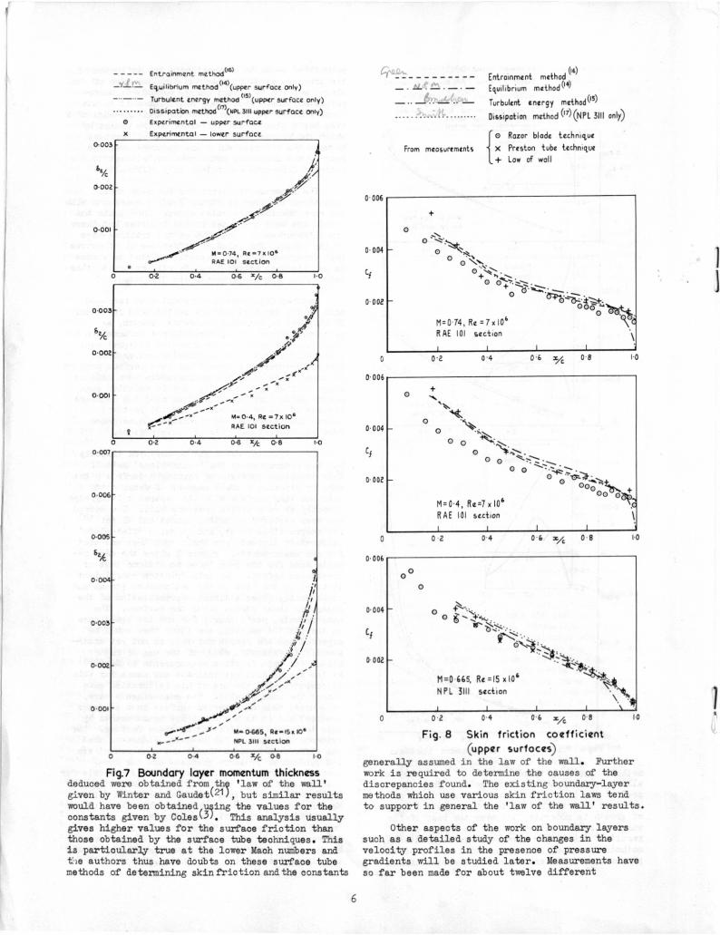
The momentumthicknessfor the sanethree conditionsis givenin Figure7 and comparisonswith thesametheoriesare alsogiven. Onceagainthe trendsare wellpredictedby the theoriesbut there are differencesof about2(g at the trailing-edgeof the wings. Thiskindof differenceis of coursevery importantas it is directlyrelatedto errorsin profile-dragestimation.We willreturnto thislaterwhen dragmeasurementsare discussed.
Anotherimportantmeasurementthathasbeenmade on theaerofoilsurfaceis the skinfriction.If thiscanbe measuredaccuratelyenough,asmentionedbefore,we havesufficientinformationtostudyall the termsin themomentumintegralequa-tionand the influenceof spanwiseconvergence.Spanwiseconvergenceshouldnotbe a seriousproblemin thesetestssincethemeasurementsweremade onwingsof high aspect-ratio,and in additionsomechecksusingsurfaceoil studiesover the outboardregionsof one of the wings(RAE101 section)showedthattherewasno significantdivergencefrom two-dimensionalflowin thoseregions.
Skinfrictioncouldnotbe measureddirectlybut was determinedby the 'razor-blade'method.This techniqueconsistsof forminga surfacepitottubeby stickinga smallsegmentof razorbladeontothe wingsurfacewithits taperedcuttingedgedirectlyabovea staticpressurehole. The m9th2dhasbeen exploredby Smith,Gaudetand Winterk18)for compressibleflows,andit was a 'flat-plate'calibrationderivedfromtheirworkthatwas usedfor ourmeasurements.Figure8 givesthemeasure-mentsmade for the samethreeconditionsthatweconsideredbefore. The skinfrictioncoefficientis basedon theflow in theundisturbedstreamandconsequentlygivesa directrepresentationof thechangein shearstressalongthe surface. Themeasurements,particularlyfor thelow speedcaseon theRAE 101 section,arelowerthanwouldbeexpectedand the reasonfor thisis notyet under-stood. A systematicstudyof theuse of razo;.bladesfor skinfrictionmeasurementsby Eastl19)at low speedsdoes notindicateany causefor thisdiscrepancy,and the use of his calibrationgavealmostthe sameresults. Themeasurementswere,of course,madeon a curvedsurfacein a pressuregradientand it is notknownhow measurementsbythistechniqueare affectedby thesefactors. Theevidenceobtainedso far however,indicatesthatthe differencebetweentheoryandmeasurementareindependentof pressuregradientand thelocalsurfacecurvature.A furthercheckwas possibleforthemeasurementson theNPL 3111sectionusingthePrestontubetech/Ape,witha calibrationdue toHopkinand Keenerk2u)for compressibleflow;thesemeasurementsarebroadlyin agreementwiththe'razorblade'method.It wasalsopossibletodeducethe skinfrictionfromthemeasurementsoftheboundarylayerprofilesnearthe wingsurfacebyassuminga 'lawof the wall'holds.The results
1.00.2 0.4 0-6 '/c 06
0.2 0.4 04 Vc 041.
0.012
0.010
0• 006
0. 004
0.002
Entrainment methcd (6) .()
Dissipation method11 (NIN. 3111-upper'Surfaceonb)(14)
(quilibrium method (upper surfag 'Only)-
Turbulent energy methodOS)
(upper surface only)Experimental — upper surface
e runentol — lower surface
0•006
0.004
0.002
PA• 0.4, Re 7.10'R A( 101 section
5
- -Entrainment methOd")
E8uiiibrium method"kupper surface only)
Turbulent energy AVOCA (*)(1411sen surface only) Dissipation methOdnliPt 3111upper surface Only)
ci Experimental — upper surface
Experimental — lower surface
Entrainment method(us)
Equilibrium method")
Turbulent energy method")
Dissipation method ('7)(NPL 3111only)
{0 Razor blade technique
From meosurements X Preston tube technique
+ Low of wall
0.2 0.4 0.6 x/c 0 8 1-0
02 0.4 0-6 ve 08 1•0
0•001
0003
byc
0.002
MA0.74, Re 7 x101RAE 101 Section
0
00
00 •4>
+O
+s'
0 0 ei-c; Natte
0
M=0 74, Re =7)(106
R AE 101 section
00
•
•0
00,D ^ter..
M=0-4, Re=1x10⁶
RAE 101 section
. .
J .'. —....
0 006
0.004
CI
1-00 2 0 4 0 6 x/c 01
02 0.4 0-6 Vc 061 1•0
0.007
0.006
0-005
0.004-
0.002
0
0 006
0 004
0 002
0
0 006
0.004
Cf
0 002
0465, Rs -i5x 106
NM_ 3111 section
0 02 0.4 06Vc 0-13 i 0
Fig.7 Boundary layer momentum thicknessdeduced were obtained from/thc 'law of the wall'given by Winter and Gaudetk21), but similar resultswould have been obtained,uging the values for theconstants given by Colesk3). This analysis usuallygives higher values for the surface friction thanthose obtained by the surface tube techniques. Thisis particularly true at the lower Mach numbers andtie authors thus have doubts on these surface tubemethods of determining skin friction and the constants
0 0 2 0 4 0 6 x, 0 8 10
Fig. 8 Skin friction coefficient(upper surfoces)
generally assumed in the law of the wall. Furtherwork is required to determine the causes of thediscrepancies found. The existing boundary—layermethods which use various skin friction laws tendto support in general the 'law of the wall' results.
Other aspects of the work on boundary layerssuch as a detailed study of the changes in thevelocity profiles in the presence of pressuregradients will be studied later. Measurements haveso far been made for about twelve different
0-003
0-002
0-001
6

conditionsof MachnuMberand lift-coefficient,thisshouldenablea systematicanalysisto beperformedovera widerangeof conditions.
As mentionedpreviouslythereis somedoubtabouttheinfluenceof thecurvedflowin theregionof thetrailingedgeof a wing. In thesetestsit was not possibleto measureflowdirec-tionsin sucha regiondue to thesmallsizeof theregionin whichsuchmeasurementswererequiredandthisis tobe doneseparatelyon a specialmodelatlowspeed. Measurements,however,weremadeof thevariationof staticpressureand thedisplacementandmomentumthicknessnearthe trailing-edgeandin the wake. Someresultsfromthesemeasurementsare givenin Figure9a wherethetotaldisplace-ment thicknessof a wingis plottedagainstchord-wisepositionfor threedifferentconditions.Thedisplacementsurfacesappeartobe reasonablysmoothnearthe trailing-edgeof the wingWhenthe wingthicknessis includedas well,but thereis afairlyrapidchangein thedisplacementsurfaceslopein theregionof the trailing-edge.
0
X Experimental pointa
0.4, ex, 0* ta,
04,-1.eite7gio.
M • 0 74,•3•0•Re7,..•
3 g
Fig.9a Displacement thickness of woke-RAE 101 section
zo
04 1-0
Fig.9b Wake shape factor - RAE 101 section
The displacementthicknessfollowsfairlycloselythe wingthicknessdistributionjustaheadof thetrailing-edgeand thenturnsrapidlyfor thenext10% chordaft of the trailing-edge.Thedisplace-ment thicknessthencontractsslowlyovertheregionup to twochordsbehindthewing,thefurthestpointbehindthewingat whichmeasure-mentsweremade. In Figure9b theshapefactorinthe wakeis givenfor thewingat zeroincidence(CL= 0). It shouldbe noted,however,thatthe
shapefactordoesnot dropto unity. In thesetests,at a Machnumberof 0.74andan inoidenoeofzero,the wakeshapefactorwas still1.3 twochordsbehindthe wingand thedisplacementthick-nesswas thereforecloselyapproximatedby
Fig.9d Variation of pressure coefficient through wake - RAE 101 section
1.3 x C1/2and not CD/2as generallyassumed. The
nextpartof thefigure(Figure9c) showsthevaria-tionof staticpressurein theregionof thetrailing-edge.Theseresults,whichare for thepressureat the centreof thewake,are consistentwiththevariationexpectedfromthedisplacementsurface,thehighestpressureoccurringwherethecurvatureis greatest.WhenconsideringWhethertheflowin the trailing-edgeregionmaybe consideredas a boundary-layer,a difficultyoccursdue to thevariationin staticpressurethroughthe layer.Measurementsof thisare shownfor threechordwiselocationsin Figure9d. It is clearthatfor thissimplecaseof a wingat zeroincidence,the staticpressuremay be consideredconstantfor all stationsotherthanthosewithina fewper centchordof thetrailing-edge.Curvatureof theflowin the sensefoundnear the trailing-edgewouldbe expectedtoleadto a changein pressureas observed.
averallForces
Lift
Fromtheevidenceavailableit is difficulttoassessthe influenceof thevariouseffectson liftdue to uncertaintiesin thewindtunnelwallcorrec-tions. Generallyspeakingpreviousevidencehassuggestedthatfor a wingsectionwithpressuredis-tributionsof theformwe haveshown,thelossinliftat the quotedReynoldsnuMberswouldbe aboutlqgfor theRAE 101 section,and perhaps2qgfor theotherwingwitha largerrearloading. The recentworkon tunnelcorrectionsindicatesthatat leastpartof thisoouldbe accountedforby tunnelcorrections.For theRAE 101sectiontheuncert-aintyin windtunnelwallcorreotionsrepresentsachangebetween2% and4 in theliftcurveslope.Figure10 givesa comparisonbetweenthe measuredliftcurveslopessand thevaluesfromexactinviscidtheory(1).Themeasuredvaluesof liftcurveslopeare within5% of the theoreticalvaluesoverthe rangewherecalculationshavebeenmade,and thisis rstherlessthanthatfoundpreviouslyat low speeds(22).An estimatefor thelossinliftexpecteddue to thecaMberof theboundary-layerdisplacementsurfaoehasbeenobtainedfromlinearisedtheoryand is alsogivenin thefigure.Thissuggeststhatabouta 691;lossin liftocours
Fig. 9c Pressure coefficient at centre of wake - RAE 101 section
oeos o!om oom 0020
.0945(.1-0011.1.04,A.OIRe.0.M°
M .0-74, et. 0°,Re3 78 10°
- 0
-Cp
-0 2
0 9 I 0 1 2 5,e 3
M• 0 4, r .0, Re I0 10 °
P0 • 0 74, • 0°, 14•7.10°
7
Slotted tunnel
CloSid tunnel
0
•Inviscid
Invisc.d + boUndOrylyir comber t//
Rs 3 3 .106
oi o6 o 6Mach mmber
FILK) Deduced liftcurveMopeftwRAE 101 section
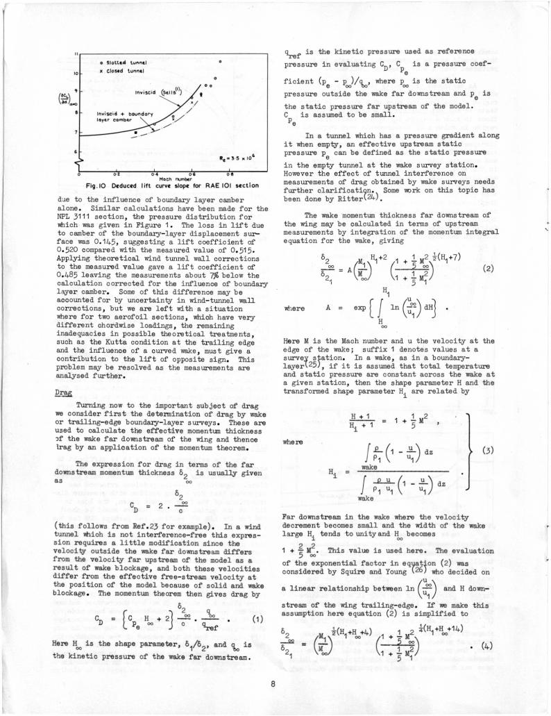
dae to the influenceof boundarylayercamberalone. Similarcalculationshavebeenmadefor theNPL3111section,the pressuredistributionforwhichwasgivenin Figure1. Thelossin liftdueto camberof theboundary-layerdisplacementsur-facewas0.145,suggestinga liftcoefficientof0.520comparedwiththemeasuredvalueof 0.515.Applyingtheoreticalwindtunnelwallcorrectionsto themeasuredvaluegavea liftcoefficientaf0.485leavingthemeasurementsabout7% belowthecalculationcorrectedfor the influenceof boundarylayercamber. Someof thisdifferencemaybea000untedfor by uncertaintyin wind-tunnelwallcorrections,but we areleftwitha situationWnerefor twoaerofoilsections,whichhaveverydifferentchordwiseloadings,theremaininginadequaciesin possibletheoreticaltreatments,suchas theKuttaconditionat thetrailingedgeandthe influenceof a curvedwake,mustgiveacontributionto theliftof oppositesign. Thisproblemmay be resolvedas themeasurementsareanalysedfurther.
Turningnow to the importantsubjectof dragwe considerfirstthedeterminationof dragby wakeor trailing-edgeboundary-layersurveys.Theseareusedto calculatetheeffectivemomentumthicknesspf thewakefar downstreamof thewingand thenceiragby an applicationof themomentumtheorem.
The expressionfor dragin termsof thefardownstreammomentumthickness62 is usnallygivenas 00
62
= 2 .CD
(thisfollowsfromRef.23forexample).In a windtunnelWhichis not interference-freethisexpres-sionrequiresa littlemodificationsincethevelocityoutsidethe wakefar downstreamdiffersfrom thevelocityfar upstreamof themodelas aresultof wake blockage,andboth thesevelocitiesdifferfromthe effectivefree-streamvelocityatthepositionof themodelbecauseof solidand wakeblockage.The momentumtheoremthengivesdragby
82
CD = [C H + 2] -== . . (1)Pe co
c gref
HereHoois the shapeparameter,61/82,and cto is
thekineticpressureof thewakefar downstream.
cirefis thekineticpressureusedas reference
pressurein evaluatingCD,Cpe is a pressurecoef-
ficient(pe - pc )/cL,wherep is the static
pressureoutsidethewakefar downstreamand pe is
the staticpressurefar upstreamof themodel.C is assumedto be small.Pe
In a tunnelwhichhasa pressuregradientalongit whenempty,an effectiveupstreamstaticpressurepe canbe definedas thestaticpressure
in theemptytunnelat thewakesurveystation.Howevertheeffectof tunnelinterferenceonmeasurementsof dragobtainedby wakesurveysneedsfurtherclarificatip.,Someworkon thistopichasbeendoneby Ritterk24).
The wakemomentumthicknessfar downstreamofthewingmaybe calculatedin termsof upstreammeasurementsby integrationof themomentumintegralequationfor thewake,giving
82M H1 1 + M+2 1 2 i(I-1.+7)00
- o. 1
82, = A (00Mi) ( 1 2)1. 5 1
H1
A = exp[ f ln (2) dii] .u1H00
HereM is theMachnumberand u thevelocityat theedgeof thewake; suffix1 denotesvaluesat asurveystation. In a wake,as in a boundary-layerl25),if it is assumedthattotaltemperatureand staticpressureare constantacrossthewakeata givenstation,thentheshapeparameterH and thetransformedshapeparameterH. arerelatedby
where
Hi -
(3)
wake
Far downstreamin thewakewherethevelocitydecrementbecomessmalland thewidthof thewakelargeHi tendstounityandqn becomes
2 2_1 + - m . Thisvalueis usedhere. Theevaluation5 00
of theexponentialfactorin eqyation(2)wasconsideredby SquireandYoung(26)whodecidedon
ua linearrelationshipbetweenln( wn= andH do-ul
streamof the wingtrailing-edge.If we makethisassumptionhereequation(2)is simplifiedto
i(H +H +4)82/111\ 1 oo (1 + 1.M2 l(H1441:14)
--L.-V.)62 = Vir) 1 a . (4)1 oo 1 +
3 ill
(2 )
where
8

le havefoundtheSquireand Youngassumptionto bea reasonableapproximationfor theshapefactorinthewakeof wingswhenthe shapefactorat thetrailing-edgeis not toolarge,i.e.theboundary-layeron eithersurfaceis not nearseparation.Figure11,however,showswhathappensin thecaseof a sectionwhenthe trailing-edgeboundary-layeron the uppersurfacehas beenconsiderablythickenedby thesevereadversepressuregradientfollowinga 55%chord'sonicrooftop'.Here thevariationof H withln(ulu1) is farfromlinear;
nevertheless,as the inserttableshows,theloss
10 12 1.4 I IS H 20 22
Fig I I Variation of H with tri (t1., u1) in wake and deduced values of profile drag
of accuracyin makingthe SquireandYoungassump-tionfrom thetrailing-edgeis notlarge. Forsurveysmadeprogressivelyfurtherdownstream,errorsdue to makingthe Squireand Youngassump-tionwilldecreaseand for theresultsshowntheyare negligiblefor surveysmademorethanaboutlogaft of thetrailing-edge.Equation(4)shouldthenbe veryaccurate.
Figure12 showsthedragresultsobtainedfromsurveysmadeat variouschordwisestationsdown-streamof the trailing-edgeby themethoddescribedabove,and theeffectof chordwisestationis, in
CD
0-008
0-001:5L
•,..2 . • 11 0
•
‘. If
0 MOmenturn method
x LOCk ,
P4x Olt
.ntevo1(Squat-ions
Hilton. goldetein
R. -
.
equation01 ond
formula
IS .104
(Z)
-
1 0 14 IS % I 8 2.0
Fig.12 Profit drag deduced from measurements at various wake stations
fact,seento be small. All the resultsare withintherangeCD = 0.0082±0.0003.Alsoshownare the
resultsof calculati9ns,madeby themethodof Lock,Hiltonand Goldsteink231.Thismethodincludestheassumptionthattotalpressureis constantalongstreamlinesin thewake,downstreamof themeasuringstation. Theseresultsare seento be about0.0002low for surveysaft of aboutlogohordfrom thetrailingedge.
In the workin the8 ft x 8 ft (2.4m x 2.4m)tunnelat Bedfordwe havebeenableto make three-componentbalancemeasurementson partof the spanof themodelnear thetunnelcentreline.A compari-son canthereforebe madebetweenthreesetsof dragmeasurements,viz. (1)wakesurveyresults,(2)balancemeasurements,and (3),integrationofsurfacepressuresand shearstresses.Balanceandpressuremeasurementsarefullycorrectedfortunnelinterferenceeffectsandpressuremeasure-mentsmustbe correctedforerrorsdue to thefinitediameterof eachorifice.Sucha comparisonis madein Figure13, Wherethefulllineis themeanof a comprehensivesetof balancemeasurements.
— 0-2 0 01 0.4 0.8 CL 0 8
Fig.I3 Drag measurements for NPL 3111 section at M=0.665; R = 15.6 x 10⁶
It mustbe pointedout however,thataccuratebalanceresultswereonlyobtainedby leavingasmall,unsealedgap of width0.02%chordat theedgesof the 'live'panel. The effectof thisgapon dragis thoughtto be smalland thisis con-firmedto someextentby thefairagreementshownbetweenthebalanceand wakesurveyresults. Thereis a tendencyin thisand otherwork,however,forwakesurveymeasurementsto givedragsa littlebelowcorrespondingbalancemeasurements.Integrationof surfacepressuresand skinfrictionis theleastpreciseof all themethods,and thisis to someextentdemonstratedby thescatterof theresults. The resultsshowgoodagreementwithothermethodsat low liftbut a considerablygreaterincreasein dragwithincreasinglift. At themomentthereasonsfor thisdiscrepancyare notfullyunderstood.
Alsoincludedin Figure13 are skinfrictiondragmeasurements.Theseare typicalof theresultsobtainedfor thiscomponent,dragbeingratherless thanthecorrespondingflat plateestimateand insensitiveto lift.
Conclusions
Ie havehighlightedsomeof thedifficultiesencounteredin makingmeasurementson two-dimensionalaerofoilsand haveindicatedsomeof theproblemswhichtheresultsshouldhelpto resolve.The analysisof theexperimentalevidenceobtained,however,is not completeandcertainfeaturesof theworkneedfurtherchecking.le set out to providea definitiveset of measurementsto help consolidatethemethodsof predictionfor loadson two-dimensionalaerofoilsat compressiblespeeds,andthismuch,we hope,we haveachieved.
CoMethod of evaluating exp(f: to (U.4u,)04
Drag Calculation
Experimental results Le. CUr ®
Straight I i ne ® 0.1 + 0.4
0-15
Measurements
0.05
0.00804
0.00790
u,
0.10
0.012
co
Balance
woke survey
Estimated 'clot plate' drag Measured— -- Skin frictia;
arog
'Sonic rooftop'
9

Symbols
CD profiledragcoefficient
C. skinfrictioncoefficient(basedon un-
disturbedstream)
CL liftcoefficient
Cm pitchingmomentcoefficient
Cp pressurecoefficient
chord
wind-tunnelheight
pressure
kineticpressure
1 boundarylayeror wake displacement6thickness
52 boundarylayeror wakemomentumthickness61
= T-, shapefactor2
Re Reynoldsnumberbasedon wingchord
MachnuMber
a angleof incidence
coefficientsfor windtunnelwallcorrections
velocity
chordwiselocationmeasuredfromleadingedgeof wing
distancefromsurfaceor chordline
Suffices
oo far downstream
farupstream
1 localvalueoutsideboundary-layeror wake
uppersurface
lowersurface
References
Sells,C.C.L.Planesubcriticalflowpastaliftingaerofoil,RAE TR 67146,1967.
KUchemann,D. Inviscidshearflownearthetrailingedgeof an aerofoil,RAETR 67068,1967.
Coles,D.E.The turbulentboundarylayerin acompressiblefluid,TheRandCorporationR-403-PR,1962.
Bradshaw,P. andFerriss,D.H.Theresponseofa retardedequilibriumturbulentboundarylayerto the suddenremovalof pressuregradient,NPL AeroReport1145,BritishARC 26758,1965
Garner,H.C.,Rogers,E.W.E.,Acura,W.E.A.andMaskell,E.C. Subsonicwindtunnelwallcorrections,AGARDograph109,1966.
Bartlett,R.S.andFirmin,M.C.P.Experimentaldeterminationof subsonicwindtunnelwallcorrections,UnpublishedMintechRpt.
Preston,J.H.Theinterferenceon a wingspan-ninga closedtunnel,arisingfromtheboundarylayeron thesidewalls,withspecialreferenceto the designof twodimensionaltunnels,BritishARC R&M 1924,1944.
Mendelsohn,R.A.andPolhamus,J.F.Effectofthe tunnel-wallboundarylayeron testresultsof a wingprotrudingfroma tunnelwall,NACATechnicalNoteNo.1244,1947.
Cook,P.H.and Firmin,M.C.P.Measurementsoftheboundarylayerand wakecharacteristicsofa two-dimensionalaerofoilat compressiblespeeds,UnpublishedMintechRpt.
Cook,T.A.and Smith,A.W.Somemeasurementsoftheboundary-layerand wakedevelopmenton twoaerofoilsectionsdesignedfor highsubsonic,sweptwingedaircraft,UnpublishedMintechRpt.
Northwong,G.J.An evaluationof fourexperi-mentalmethodsfor measuringmeanpropertiesofa supersonicturbulentboundarylayer,NACAReport1320,1957.
Preston,J.H.andSweeting,N.E.Theexperi-mentaldeterminationof theboundarylayerandwakecharacteristicsof a simpleJoukowskiaerofoil,withparticularreferenceto thetrailingedgeregion,BritishARC R&M 1998,1943.
Preston,J.H.,Sweeting,N.E.and Cox,D.K.The experimentaldeterminationof theboundarylayersand wakecharacteristicsof a Piercy12/40aerofoil,withparticularreferencetothe trailingedgeregion,BritishARCR&M 2013,1945.
Nash,J.F.andMacdonaldA.G.T.The calculationof momentumthicknessin a turbulentboundarylayerat Machnumbersup to unity.NPLAeroReport1270,BritishARC 28,235,1966.
Bradshaw,P. andFerriss,D.H.Calculationofboundary-layerdevelopmentusingtheturbulentenergyequationII - Compressibleflowonadiabaticwalls,NPLAeroReport1217,BritishARC 28,541,1966.
Green,J.E.The predictionof turbulentboundary-layerdevelopmentin compressibleflow,J. FluidMech.Vol.31part4, 1968.
Winter,K.G.,Smith,K.G.and Rotta,J.C.Turbulentboundarylayerstudieson a waistedbodyof revolutionin subsonicand supersonicflow,AGARDograph97 (Part2) PP- 933-962,1965.
Smith,K.G.,Gaudet,L. and linter,K.G.The useof surfacepitottubesas skinfrictionmeteratsupersonicspeeds,BritishARC R&M 3351,1962
East,L.F.Measurementof skinfrictionat lowsubsonicspeedsby therazor-bladeteohnique.RAE TR 66277,1966.
*0,*1
10

Hopkins,E.J.and Keener,E.R.Studyof surfacepitotsfor measuringturbulentskinfrictionatsupersonicMachnumbers- adiabaticwall.NASATN D 3478,1966.
Gaudet,L. and Winter,K.G.Turbulentboundary-layerstudiesat highReynoldsnuMbers,atMach numbersbetween0.2 and 2.8,UnpublishedMinteohRpt.
Brebner,G.G.and Bagley,J.A.Pressureandboundarylayermeasurementson a two-dimensionalwingat low speed,BritishARC R&M 2886,1956.
Lock,C.W.H.,Hilton,W.F.andGoldstein,S.Determinationof profiledragat highspeedsby a pitottraversemethod,BritishARC R&M1917,1940.
Ritter,H. Waketraversein thepresenceoftunnelblockage,AdmiraltyResearchLab.Teddington,Middx,England,ARL/G/NA,1963.
Spence,D.A.The growthof compressibleturbulentboundarylayerson isothermalandadiabaticwalls,RAE ReportAero2619,1959.
Squire,H.B.and Young,A.D.The calculationof profiledragof aerofoils,BritishARC R&M1838,1937.
11


![Nicrom Electronic General Catalog · PDF fileresolution CRT displays, Radar Systems, ... 0.80 ± 0.10 [0.031 ± 0.004] 0.50 [0.020] 0.25 ± 0.10 [0.010 ± 0.004] 0.80 [0.032] 1206](https://img.dokumen.tips/doc/110x75/5abdeed47f8b9aa3088c4516/nicrom-electronic-general-catalog-crt-displays-radar-systems-080-010-0031.jpg)


![arXiv:1606.04142v1 [cs.IT] 13 Jun 2016 · 0 0.001 0.002 0.003 0.004 0.005 0 0.01 0.02 0.03 0.04 0.05 D r Wigner Spike model DAMP DOpt Dspectral 0 0.001 0.002 0 0.0001 0.0002 0.0003](https://img.dokumen.tips/doc/110x75/60cab98b180634579f3f63df/arxiv160604142v1-csit-13-jun-2016-0-0001-0002-0003-0004-0005-0-001-002.jpg)


