Embed Size (px)
Citation preview

International Civil Aviation Organization
Approved by the Secretary General
and published under his authority
First Edition — 2010
Doc 9924
AN/474
Aeronautical Surveillance
Manual


Doc 9924 AN/474
Approved by the Secretary Generaland published under his authority
First Edition — 2011
International Civil Aviation Organization
Aeronautical Surveillance Manual
________________________________

Published in separate English, French, Russian and Spanish editions by the INTERNATIONAL CIVIL AVIATION ORGANIZATION 999 University Street, Montréal, Quebec, Canada H3C 5H7 For ordering information and for a complete listing of sales agents and booksellers, please go to the ICAO website at www.icao.int Doc 9924, Aeronautical Surveillance Manual Order Number: 9924 ISBN 978-92-9231-690-7 © ICAO 2011 All rights reserved. No part of this publication may be reproduced, stored in a retrieval system or transmitted in any form or by any means, without prior permission in writing from the International Civil Aviation Organization.

(iii)
AMENDMENTS
Amendments are announced in the supplements to the Catalogue of ICAO Publications; the Catalogue and its supplements are available on the ICAO website at www.icao.int. The space below is provided to keep a record of such amendments.
RECORD OF AMENDMENTS AND CORRIGENDA
AMENDMENTS CORRIGENDA
No. Date Entered by No. Date Entered by
1 5/4/12 ICAO 1 16/2/12 ICAO


(v)
TABLE OF CONTENTS
Page
Foreword .................................................................................................................................................. (vii) Explanation of terms ............................................................................................................................... (viii) Acronyms and abbreviations ................................................................................................................. (xvi) References ............................................................................................................................................... (xx) 1. Introduction .............................................................................................................................................. 1-1 1.1 Overview ............................................................................................................................................ 1-1 1.2 The need for aeronautical surveillance .............................................................................................. 1-1 2. Surveillance system definition ............................................................................................................... 2-1 2.1 Surveillance system purpose and scope ........................................................................................... 2-1 2.2 Surveillance categories...................................................................................................................... 2-1 3. Applications of air traffic surveillance ................................................................................................... 3-1 3.1 Introduction ........................................................................................................................................ 3-1 3.2 Aircraft identity ................................................................................................................................... 3-6 3.3 Operational use of surveillance data ................................................................................................. 3-6 4. Technical performance requirements for surveillance systems ......................................................... 4-1 4.1 Purpose ............................................................................................................................................. 4-1 4.2 Definition of parameters contributing to quality of services ................................................................ 4-1 4.3 Other performance-related issues ..................................................................................................... 4-2 5. Air-ground surveillance systems ........................................................................................................... 5-1 5.1 Components of an aeronautical surveillance system ......................................................................... 5-1 5.2 Non-cooperative sensor ..................................................................................................................... 5-1
5.3 Independent cooperative sensor systems ......................................................................................... 5-4 5.4 Dependent cooperative systems ....................................................................................................... 5-10 5.5 SDP systems ..................................................................................................................................... 5-15 5.6 Surveillance data distribution by ASTERIX ........................................................................................ 5-15 6. Airborne surveillance .............................................................................................................................. 6-1 6.1 Introduction ........................................................................................................................................ 6-1 6.2 ADS-B IN ........................................................................................................................................... 6-1 6.3 TIS-B .............................................................................................................................................. 6-1 6.4 ADS-R .............................................................................................................................................. 6-2 6.5 ACAS .............................................................................................................................................. 6-2 6.6 Displays for airborne surveillance ...................................................................................................... 6-3 7. Surveillance system deployment considerations ................................................................................. 7-1 7.1 Best practices checklist ..................................................................................................................... 7-1 7.2 Transition to dependent surveillance systems ................................................................................... 7-2 7.3 Other issues ...................................................................................................................................... 7-3

(vi) Aeronautical Surveillance Manual
Page
APPENDICES Appendix A: Technical performance requirements ........................................................................................ A-1 Appendix B: PSR ........................................................................................................................................... B-1 Appendix C: SSR performance capabilities ................................................................................................... C-1 Appendix D: SSR system techniques ............................................................................................................. D-1 Appendix E: MSSR ........................................................................................................................................ E-1 Appendix F: Mode S and Mode A/C compatibility .......................................................................................... F-1 Appendix G: Mode S error detection and correction ....................................................................................... G-1 Appendix H: Mode S protocol considerations................................................................................................. H-1 Appendix I: Mode S specific services ........................................................................................................... I-1 Appendix J: Mode S implementation ............................................................................................................. J-1 Appendix K: 1 090 MHz ES ........................................................................................................................... K-1 Appendix L: MLAT ......................................................................................................................................... L-1 Appendix M: MHz interference considerations ............................................................................................... M-1 Appendix N: ASTERIX interface specification ................................................................................................ N-1 Appendix O: Airborne surveillance equipment installation and test considerations ........................................ O-1
______________________

(vii)
FOREWORD
Air traffic is growing at a significant rate and at the same time, there are increasing demands for more operating flexibility to improve aircraft efficiency and to reduce the impact of air travel on the environment. Aeronautical surveillance systems are major elements of modern air navigation infrastructure required to safely manage increasing levels and complexity of air traffic. This manual has been produced by the Aeronautical Surveillance Panel (ASP) as a reference document consolidating the updated guidance material previously published in other manuals with new material covering more recent or emerging techniques. The chapters provide the reader with a basic understanding of various systems and how they are used for air traffic surveillance while the appendices contain detailed information on some specific systems and related topics. Comments on this manual from States and other parties outside ICAO concerned with surveillance system development and provision of services would be appreciated and should be addressed to:
The Secretary General International Civil Aviation Organization 999 University Street Montréal, Quebec H3C 5H7 Canada
______________________

(viii)
EXPLANATION OF TERMS
Acquisition squitter. The spontaneous periodic transmission by a Mode S transponder (nominally once per second) of a specified format, including the aircraft address, to permit passive acquisition.
Aircraft. Any machine that can derive support in the atmosphere from the reactions of the air other that the reaction of
the air against the earth’s surface. Note.— In the context of aeronautical surveillance, the term “aircraft” should be understood as “aircraft or vehicle (A/V).” Aircraft address. A unique combination of 24 bits that is available for assignment to an aircraft for the purpose of
communications, navigation and surveillance. Note.— The aircraft address is sometimes referred to as the Mode S address, the aircraft Mode S address, or the 24-bit address. Aircraft identification. A group of letters, figures or a combination thereof which is either identical to, or the coded
equivalent of, the aircraft call sign to be used in air-ground communications, and which is used to identify the aircraft in ground-ground or air traffic services communications.
Note.— The aircraft identification is also referred to as flight identification. All-call. An intermode or Mode S interrogation that elicits replies from more than one transponder. All-call (Mode A/C-only). An intermode interrogation that elicits replies from Mode A/C transponders only. Mode S
transponders do not accept this interrogation. All-call (Mode S-only). A Mode S interrogation that elicits all-call replies from Mode S transponders that are currently
not in the lockout state for that interrogator code. All-call (stochastic). A Mode S-only all-call that elicits all-call replies from only a random subset of the Mode S
transponders that are currently not in the lockout state. Antenna diversity. An installation that consists of top and bottom mounted antennas that is used in SSR, ACAS and
ADS-B systems to improve the transmission and reception capabilities. Altitude. The vertical distance of a level, point or an object measured above mean sea level. Antenna (electronically scanned, E-Scan). An SSR antenna consisting of a number of planar arrays or a circular array
of radiating elements. A beam former unit allows it to electronically steer the beam to the desired azimuth angle by applying phase shifting. The antenna elements may either be active or passive, depending on the order in which the beam former and transmitters are set up.

Explanation of Terms (ix)
Antenna (hog-trough). An SSR antenna comprising a horizontal linear array of radiating elements installed in an extended corner reflector assembly (resembling in shape a hog-trough). The linear array is usually of sufficient length to give an azimuth beamwidth of between 2 and 3 degrees, and the hog-trough reflector achieves typically between ±40 and 45 degrees vertical beamwidth. For special purposes shorter arrays can be used. These have increased azimuth beamwidth.
Antenna (large vertical aperture LVA). An SSR antenna comprising two-dimensional array radiating elements. A
typical LVA consists of a number of columns (each consisting of a vertical linear array designed to produce beam shaping in the vertical plane) arranged in a horizontal linear array to produce an azimuth beamwidth of between 2 and 3 degrees. LVA antennas are widely used for monopulse SSR systems.
Antenna (linear array). An antenna consisting of an array of radiating elements in a straight line. The desired radiation
characteristic of the antenna is obtained by the varied distribution of radio frequency energy in amplitude or phase so as to produce the shaped “beam” or wave front.
Antenna (monopulse). See antenna (sum and difference). Antenna (omnidirectional). An antenna with the same gain in all directions. Antenna (sum and difference). A hog-trough or LVA antenna which is electrically split into two halves. The two half-
antenna outputs are added in phase at one output port (sum, Σ) and added in anti-phase at a second output port (difference, Δ) to produce output signals which are sensitive to the azimuth angle of arrival of received signals, enabling an off-boresight angle for the signal source to be obtained. This kind of antenna is required for monopulse and Mode S operation.
Antenna (reflector). An antenna producing the beam by a method analogous to optics. In most cases the “reflector”
surface of the antenna is illuminated by a radio frequency source (e.g. a radio-frequency “horn” assembly). The dimensions of the reflector antenna both in the horizontal and vertical plane, together with the characteristics of the illuminating source, determine the shape and magnitude of the radar beam produced.
BDS1 code. The BDS1 code is defined in the RR field of a surveillance or Comm-A interrogation. BDS2 code. The BDS2 code is defined in the RRS of the SD field of a surveillance or Comm-A interrogation when
DI = 7. If no BDS2 code is specified (i.e. DI ≠ 7), it signifies that BDS2 = 0. Beamwidth. An angle subtended (either in azimuth or elevation) at the half-power points (3 dB below maximum) of the
main beam of an antenna. Boresight. A main lobe electrical (radio) axis of an antenna. Capability report. An indication provided by the capability (CA) field of an all-call reply and a squitter transmission of the
communications capability of the Mode S transponder (see also “data link capability report”), and some information on the aircraft status.
Chip. A 0.2-microsecond carrier interval following possible data phase reversals in the P6 pulse of Mode S interrogations
(see “data phase reversal”). Closeout. A command from the Mode S ground station that terminates a communication transaction. Cluster. A set of Mode S interrogators with overlapping coverage that use the same interrogator code. The interrogators
communicate with each other to provide acquisition or reacquisition to neighbouring interrogators. The cluster operation requires fewer interrogator codes, and Mode S aircraft within the cluster airspace normally remain in a state of lockout, which reduces Mode S all-call transmissions.

(x) Aeronautical Surveillance Manual
Comm-A. A 112-bit interrogation containing the 56-bit MA message field. This field is used by the uplink standard length message (SLM) and broadcast protocols.
Comm-B. A 112-bit reply containing the 56-bit MB message field. This field is used by the downlink SLM, ground-
initiated and broadcast protocols. Comm-B data selector (BDS). The 8-bit BDS code in a surveillance or Comm-A interrogation determines the register
whose contents are to be transferred in the MB field of the elicited Comm-B reply. The BDS code is expressed in two groups of 4 bits each, BDS1 (most significant 4 bits) and BDS2 (least significant 4 bits).
Comm-C. A 112-bit interrogation containing the 80-bit MC message field. This field is used by the extended length
message (ELM) uplink protocol for uplink data transfer and by the downlink ELM protocol for the transfer of segment readout commands.
Comm-D. A 112-bit reply containing the 80-bit MD message field. This field is used by the extended length message
(ELM) downlink protocol for downlink data transfer and by the uplink ELM protocol for the transfer of technical acknowledgements.
Control antenna. An SSR antenna having a polar diagram which is designed to “cover” the side lobes of the main
interrogating antenna. It is used to radiate a control pulse which, if it exceeds in amplitude the associated interrogation signal at the input to the transponder, will cause the transponder to inhibit responses to the interrogation pulses. Modern SSR antennas have the control elements built into the main array. The control antenna is also known as the SLS (side-lobe suppression) antenna. In earlier SLS systems, an omnidirectional antenna was often used for transmitting the P2 pulse and sometimes also for transmission of the P1 pulse (I2SLS). Modern antennas for ground SSR use include a “notch” coinciding with the peak of the main beam.
Control pattern. A polar diagram of the control antenna. Modern integrated SSR antennas have a “modified cardioid”
beam shape. Control pulse. A pulse (P2 for Modes A and C, P5 for Mode S) transmitted by the ground equipment (SSR interrogator)
in order to ensure side-lobe suppression. Correlation criteria. A number of pulse repetition intervals over which range correlation of replies must be achieved in a
sliding or moving window extractor before the presence (or tentative presence, subject to further tests) of a plot can be declared.
Data link capability report. Information in a Comm-B reply identifying the complete Comm-A, Comm-B, ELM and
ACAS capabilities of the aircraft installation. Data phase reversal. A 180-degree phase shift in a Mode S interrogation that is used to encode a binary ONE. The
absence of the phase reversal encodes a binary ZER Dead time. A period of time during which an SSR transponder is inhibited from receiving signals after a valid
interrogation is received and a reply transmitted. The term is also used to describe the time after the normal range for returns and before the next transmission from an interrogator or from a primary radar system.
Defruiter. Equipment used to eliminate unsynchronized replies (FRUIT) in an SSR ground system. Defruiting. A process by which aircraft replies accepted by the interrogator-receiver are tested by means of storage and
a comparator for synchronism with the interrogation-repetition frequency. Only replies which are in synchronism (correlate on a repeated basis in range) will be output from the defruiter. Other replies are rejected as “FRUIT.”

Explanation of Terms (xi)
Difference pattern. A receive (1 090 MHz) characteristic of a monopulse SSR antenna, obtained by connecting in anti-phase the signals (replies) received by two partial antennas. The difference pattern has a minimum in the main radiation direction of the antenna and an amplitude and phase characteristic which varies as a function of angle of arrival of the received signal. Used in conjunction with the sum output of the antenna, it enables the off-boresight angle to be found.
Differential phase-shift keying (DPSK). Modulation which uses phase reversals preceding chips to denote binary
ONEs and the absence of a phase reversal to denote binary ZEROs. Downlink. Associated with signals transmitted on the 1 090 MHz reply frequency channel. Effective radiated power (ERP). The transmitted power enhanced by the gain of the antenna less the losses in cables,
rotary joints, etc. Extended length message (ELM) protocol. A series of Comm-C interrogations (uplink ELM) transmitted without the
requirement for intervening replies, or a series of Comm-D replies (downlink ELM) transmitted without intervening interrogations.
Extended squitter. Spontaneous periodic transmission of a 1 090 MHz 112-bit Mode S signal format containing 56 bits
of additional information (e.g. used for ADS-B, TIS-B and ADS-R). False plot. A radar plot report which does not correspond to the actual position of a real aircraft (target), within certain
limits. Field. A defined number of contiguous bits in an interrogation, reply or squitter. Flight identification. See aircraft identification. Flight status (FS) field. A field of a Mode S reply indicating if the aircraft is airborne or on-ground, is transmitting the
Mode A/C SPI code or has recently changed its Mode A identity code. Framing pulses. Pulses which “frame” the information pulses (code) of SSR Modes A and C replies (described as F1
and F2, respectively), also known as “bracket pulses.” FRUIT. A term applied to unwanted SSR replies received by an interrogator which have been triggered by other SSR
interrogators. FRUIT is the acronym for false replies unsynchronized in time. Gain (of antenna). A measure for the antenna of the increased (effective) transmitted power density radiated in a
particular direction as compared to the power density that would have been radiated from an isotropic antenna (expressed in dB).
Galileo. Europe’s own global navigation satellite system, providing a highly accurate, guaranteed global positioning
service under civilian control. Garbling. A term applied to the overlapping in range and/or azimuth of two or more SSR replies so that the pulse
positions of one reply fall close to or overlap the pulse positions of another reply, thereby making the decoding of reply data prone to error.
Ground-initiated Comm-B (GICB) protocol. A procedure initiated by a Mode S ground station for eliciting a Comm-B
message containing aircraft derived data from a Mode S aircraft installation.
(xii) Aeronautical Surveillance Manual
Improved interrogator side-lobe suppression (I2SLS). A technique whereby interrogation pulse P1 is transmitted via both the main beam and the control beam of the SSR antenna, so that a transponder in a side-lobe direction more reliably receives a P1-P2 pulse pair.
Intermode interrogations. Interrogations that consist of 3 pulses (P1, P3 and P4) and are capable of eliciting replies a)
from both Mode A/C and Mode S transponders or b) from Mode A/C transponders but not from Mode S transponders (see “All-call”).
Interrogator. A surveillance system transmitting on 1 030 MHz. The surveillance system may be fixed or mobile. Interrogator code (IC). A code used to identify an interrogator in Mode S protocols. It may be either an interrogator
identifier (II) or surveillance identifier (SI) code. Interrogator identifier (II). One of the codes (1 to 15) used to identify a Mode S ground station using the multisite
protocols. Interrogator (mobile). An airborne, ship-borne or ground transportable interrogator. The term “mobile interrogator” is
usually used for military installations. Interrogator repetition frequency (IRF). An average number of interrogations per second transmitted by the radar.
Sometimes referred to as “Pulse repetition frequency” (PRF). Interrogator side-lobe suppression (ISLS). A method of preventing transponder replies to interrogations transmitted
through the ground antenna side lobes. Lobing (antenna pattern). A process whereby, due to interference of two waves, one direct and one reflected,
differences in phases cause larger or smaller amplitudes than expected for free space, causing differences in signal amplitudes.
Lockout state. A state in which a Mode S transponder has been instructed not to accept certain all-call interrogations.
Lockout is deliberately induced by command from the Mode S ground station. Mode. SSR interrogation mode as specified in Annex 10, Volume IV, Chapter 2. Mode A/C transponder. Airborne equipment that generates specified responses to Mode A, Mode C and intermode
interrogations but does not reply to Mode S interrogations. Mode S. An enhanced mode of SSR that permits selective interrogation and reply capability. Mode S ground station. Ground equipment that interrogates Mode A/C and Mode S transponders using intermode and
Mode S interrogations. A monopulse capable antenna and a rotary joint providing at least two channels for sum and difference processing are a pre-requisite for Mode S operation.
Mode S interrogations. Interrogations consisting of three pulses (P1, P2 and P6) that convey information to and/or elicit
replies from Mode S transponders. Mode A/C transponders do not respond to Mode S interrogations because they are suppressed by the (P1-P2) pulse pair.
Mode S surveillance interrogation. A 56-bit Mode S interrogation containing surveillance and communications control
information. Mode S surveillance reply. A 56-bit Mode S reply containing surveillance and communications control information, plus
the aircraft’s 4 096 identity code or altitude code.

Explanation of Terms (xiii)
Mode S transponder. Airborne equipment that generates specified responses to Mode A, Mode C, intermode and Mode S interrogations.
Monopulse. A technique wherein the amplitudes and/or phases of the signals received in overlapping antenna lobes are
compared to estimate the angle of arrival of the signal. The technique determines the angle of arrival of a single pulse, or reply, within an antenna beamwidth. The angle of arrival is determined by means of a processor using the replies received through the sum and difference patterns of the antenna. The monopulse technique is generally termed “monopulse direction finding.”
Monopulse plot extractor. A plot extractor using monopulse direction-finding techniques. See also plot extractor. Multisite Comm-B protocol. A procedure to control air-initiated Comm-B message delivery to Mode S ground stations
that have overlapping coverage and that are operating independently (see “multisite protocol”). Multisite-directed Comm-B protocol. A procedure to ensure that a multisite Comm-B message closeout is effected
only by the particular Mode S ground station selected by the Mode S airborne installation. Multisite protocol. Procedures to control message interchange between a Mode S transponder and Mode S ground
stations with overlapping coverage operating independently. Multisite protocols allow only a single Mode S ground station to closeout a message interchange, thereby assuring that independent operation of Mode S ground stations does not cause messages to be lost.
Non-selective protocol. Procedures to control message interchange between a Mode S transponder and Mode S
ground stations operating alone or in overlapping coverage with operations coordinated via ground communications.
PARROT. A fixed transponder referred to as the position adjustable range reference orientation transponder and used
as a field monitor (see “remote field monitor”). Plot extractor. Signal processing equipment which converts PSR and/or SSR video into an output data message
suitable for transmission through a data transmission medium or possibly to further data processing equipment. Pulse repetition frequency (PRF). An average number of pulses/interrogations per second transmitted by the radar
(see “stagger”). Also known as pulse recurrence frequency. Pulse train. A sequence of framing and information pulses in the coded SSR reply. Receiver side-lobe suppression (RSLS). A method that uses two (or more) receivers to suppress aircraft replies which
have been received via side lobes of the main beam of the antenna. Remote field monitor. A system which monitors the uplink and/or downlink performance of an SSR or Mode S system
from a site located at the specified distance from the radar (far field). The monitor (see “PARROT”) is interrogated by the radar, and its replies can be evaluated on the radar site. In addition, the replies may contain data about certain interrogation parameters as seen by the monitor.
Reply. A pulse train received at an SSR ground station as a result of successful SSR interrogation. Reply preamble. A sequence of four pulses, each with a duration of 0.5 microsecond, indicating the beginning of a
Mode S reply. Resolution. Ability of a system to distinguish between two or more targets in close proximity to each other both in range
and bearing (azimuth).

(xiv) Aeronautical Surveillance Manual
Ring-around. Continuous reception of replies to interrogations by the side lobes of the ground antenna. This normally occurs only at short ranges, usually due to the non-existence of a side-lobe suppression mechanism or the improper functioning of this mechanism, at either the interrogator or the transponder side.
Round trip reliability. A probability of receipt of a correct reply, resulting from either an SSR interrogation or a PSR
transmission. Secondary surveillance radar (SSR) system. A surveillance radar system which uses transmitters/receivers
(interrogators) and transponders. Secondary surveillance radar (SSR) transponder. A unit which transmits a response signal on receiving an SSR
interrogation. The term is a derivative of the words transmitter and responder. Side lobes (antenna). Lobes of the radiation pattern of an antenna, which are not part of the main or principal beam.
Radar systems can have sufficient sensitivity via side lobes for successful detection of aircraft (particularly for SSR, but also for PSR). Special precautions are necessary to protect against these false plots.
Side-lobe suppression (SLS). A mechanism in an SSR transponder activated by the transmission (radiation) of a
control pulse (P2 or P5) which will enable the transponder to prevent itself from replying to the side-lobe interrogation signals.
Stagger. Deliberate, controlled variation of the pulse repetition frequency of the SSR to prevent aircraft plots due to
second-time-around replies. Standard length message (SLM) protocol. A procedure to exchange digital data using Comm-A interrogations and/or
Comm-B replies. Sum pattern. Normal radiation pattern for the main directional beam of an antenna. It contrasts with the “difference-
pattern,” where parts of the radiating elements of the antenna are switched in anti-phase to produce signals proportional to the amount by which the source is off the boresight of the sum pattern.
Suppression. A deliberate inhibition of a transponder’s ability to accept or reply to interrogations. Surveillance identifier (SI). One of the codes (1 to 63) used to identify a Mode S ground station using only surveillance
or limited communications protocols. These codes were added to provide additional codes for surveillance purposes.
Surveillance processing. A general term covering any processing applied to the target reports after the extraction
functions and prior to the data transmission functions. Such processes include filtering, clutter reduction, data rate control and dynamic angle control.
Sync phase reversal. A first phase reversal in the Mode S P6 interrogation pulse. It is used to synchronize the circuitry
in the transponder that decodes the P6 pulse by detecting data phase reversals, i.e. as a timing reference for subsequent transponder operations related to the interrogation.
Track. The projection on the earth’s surface of the path of an aircraft, the direction of which at any point is usually
expressed in degrees from north (true, magnetic or grid). Transponder transaction cycle. The sequence of transponder operations required by the reception of an interrogation.
The process begins with the recognition of an interrogation and ends either with the non-acceptance of the interrogation or the transmission of a reply or the completion of processing associated with that interrogation.

Explanation of Terms (xv)
Uplink. Associated with signals transmitted on the 1 030 MHz interrogation frequency channel. Validation (code). Process of correlation of the code information used in SSR Mode A/C systems. Generally two
identical codes in two successive replies suffice to validate the code. In Mode S, code validation occurs inherently when the reply is decoded (and, if appropriate, the error is corrected).
______________________

(xvi) 5/4/12 No. 1
ACRONYMS AND ABBREVIATIONS
ACAS Airborne collision avoidance system ADLP Airborne data link processor ADS-B Automatic dependent surveillance — broadcast ADS-C Automatic dependent surveillances — contract ADS-R ADS-B rebroadcast AICB Air-initiated Comm-B AIS Aircraft identification subfield AOA Angle of arrival AP Address parity A-SMGCS Advanced — surface movement guidance and control systems ASA Airborne surveillance application ASDE Airport surface detection equipment ASP Aeronautical surveillance panel ASTERIX All purpose structured Eurocontrol surveillance information exchange ATC Air traffic control ATCO Air traffic controller ATM Air traffic management ATN Aeronautical telecommunication network ATS Air traffic service ATSAW Airborne traffic situational awareness A/V Aircraft/vehicle BDN Broadcast downlink BDS Comm-B data selector BDS1 Most significant 4 bits of BDS BDS2 Least significant 4 bits of BDS BUP Broadcast uplink CA Capability (as in capability field) CC Cross-link capability CDTI Cockpit display of traffic information CL Code label cm Centimetre CNS Communications, navigation and surveillance CPDLC Controller-pilot data link communications CPR Compact position reporting CRC Cyclic redundancy check CW Continuous wave DAP Downlink aircraft parameters DCE Data circuit-terminating equipment DELM Downlink extended length message DF Downlink format DI Designator identifier DME Distance measuring equipment DPSK Differential phase-shift keying DR Downlink request DS Data selector DTE Data terminal equipment

Acronyms and Abbreviations (xvii)
5/4/12No. 1
EHS Enhanced surveillance ELM Extended length message ELS Elementary surveillance ERP Effective radiated power ES Extended squitter E-SCAN Electronically scanned EUROCAE European Organization for Civil Aviation Equipment FDPS Flight data processing system FIS Flight information service FMS Flight management system FOD Foreign object debris FOM Figure of merit FPPS Flight plan processing system FRN Field reference number FSPEC Field specification FRUIT False replies from unsynchronized interrogator transmissions in time FS Flight status ft Foot GDLP Ground data link processor GDOP Geometric dilution of precision GICB Ground-initiated Comm-B GNSS Global navigation satellite system HDOP Horizontal dilution of precision HF High frequency HMI Human-machine interface HRP Horizontal radiation pattern IC Interrogator code ID Identification (as in aircraft identification) IDS Identifier designator subfield IF Intermediate frequency IFF Identification of friend or foe IFR Instrument flight rules II Interrogator identifier IIS Interrogator identifier subfield IMC Instrument meteorological conditions IRF Interrogator repetition frequency ISLS Interrogator side-lobe suppression I2SLS Improved interrogator side-lobe suppression ISO International Organization for Standardization km Kilometre kt Knot LOS Lockout subfield LVA Large vertical aperture m Metre MA Message Comm-A MB Message Comm-B MBS Multisite Comm-B subfield MC Message Comm-C MD Message Comm-D MDN MSP downlink MES Multisite ELM subfield MHz Megahertz MIP Mode Interface pattern

(xviii) Aeronautical Surveillance Manual
5/4/12 No. 1
MLAT Multilateration system ms Millisecond MSAW Minimum safe altitude warning MSO Message start opportunity MSP Mode S specific protocol MSPSR Multistatic primary surveillance radar MSSR Monopulse SSR MTL Minimum triggering level MUP MSP uplink NC Number of C-segment NIC Navigation integrity category NM Nautical mile ns nanosecond NUC Navigation uncertainty category OBA Off-boresight angle OSI Open systems interconnection PAR Precision approach radar PARROT Position adjustable range reference orientation transponder PRM Precision runway monitor PC Protocol (as in protocol field) PD Probability of detection PI Parity/interrogator identifier PPI Plan position indicator PR Probability of reply PRF Pulse repetition frequency PSR Primary surveillance radar RA Resolution advisory RDPS Radar data processing system RF Radio frequency RL Reply length RMS Root mean square RNP Required navigation performance RR Reply request RRS Reply request subfield RSLS Receiver side-lobe suppression RSS Reservation status subfield RVSM Reduced vertical separation minimum s Second SAC System area code SD Special designator SDP Surveillance data processing SI Surveillance identifier SIC System identification code SIL Surveillance integrity level SLM Standard length message SLS Side-lobe suppression SMR Surface movement radar SNPA Subnetwork points of attachment SNR Signal-to-noise ratio SPI Special position identification SR Service request SRS Segment request subfield SSE Specific services entity

Acronyms and Abbreviations (xix)
5/4/12No. 1
SSR Secondary surveillance radar STC Sensitivity time control STCA Short-term conflict alert SVC Switched vertical circuit TA Traffic advisory TACAN Tactical air navigation TAS Technical acknowledgement subfield TCAS Traffic alert and collision avoidance system TCP Transmission control protocol TCS Type control subfield TDMA Time division multiple access TDOA Time difference of arrival TDOP Time dilution of precision TIS Traffic information service TIS-B Traffic information service — broadcast TOA Time of arrival TRS Transmission rate subfield UAP User application profile UAS Unmanned aerial systems UAT Universal access transceiver UDP User datagram protocol UF Uplink format UM Utility message UTC Coordinated universal time VDLM4 VHF digital link Mode 4 VHF Very high frequency VRP Vertical radiation pattern VS Vertical status VSWR Voltage standing wave ratio WAM Wide area multilateration WGS World geodetic system
______________________

(xx)
REFERENCES
ICAO Annex 10 — Aeronautical Telecommunications, Volume III — Communication Systems, Part I — Digital Data
Communication Systems and Part II — Voice Communication Systems; and Volume IV — Surveillance and Collision Avoidance Systems.
Doc 4444 — Procedures for Air Navigation Services — Air Traffic Management (PANS-ATM). Doc 8071 — Manual on Testing of Radio Navigation Aids, Volume III — Testing of Surveillance Radar Systems. Doc 8168 — Procedures for Air Navigation Services — Aircraft Operations (PANS-OPS). Doc 8585 — Designators for Aircraft Operating Agencies, Aeronautical Authorities and Services. Doc 9476 — Manual of Surface Movement Guidance and Control Systems (SMGCS). Doc 9816 — Manual on VHF Digital Link (VDL) Mode 4. Doc 9830 — Advanced Surface Movement Guidance and Control Systems (A-SMGCS) Manual. Doc 9861 — Manual on the Universal Access Transceiver (UAT). Doc 9863 — Airborne Collision Avoidance System (ACAS) Manual. Doc 9871 — Technical Provisions for Mode S Services and Extended Squitter. European Organization for Civil Aviation Equipment (EUROCAE) EUROCAE ED-73C, MOPS for Secondary Surveillance Radar Mode S Transponders. EUROCAE ED-117, MOPS for Mode S Multilateration Systems for Use in A-SMGCS. EUROCAE ED-142, Technical Specifications for Wide Area Multilateration System (WAM). RTCA RTCA/DO-181D, Minimum Operational Performance Standards for Air Traffic Control Radar Beacon System/Mode
Select (ATCRBS/Mode S) Airborne Equipment RTCA/DO-260, Minimum Operational Performance Standards for 1090 MHz Automatic Dependent Surveillance —
Broadcast (ADS-B)

References (xxi)
RTCA/DO-260A, Minimum Operational Performance Standards for 1090 MHz Extended Squitter Automatic Dependent Surveillance — Broadcast (ADS-B) and Traffic Information Services — Broadcast (TIS-B)
Others EUROCONTROL Study P726D005, “Use of Squitter to Mitigate IC Conflicts”, A. Burrage et al, 27 July 2007. MIT LL Project Report ATC-248, “Six-Sector Antenna for the GPS-Squitter En-Route Ground Station” M.L. Burrows, 31 May 1996. This report is available at: http://www.ll.mit.edu/mission/aviation/publications/publication-files/atc-reports/Burrows_1996_ATC_248_WW-15318.pdf
______________________
5/4/12No. 1


1-1
Chapter 1
INTRODUCTION
1.1 OVERVIEW 1.1.1 Air traffic is growing at a significant rate. There is also an increasing demand for more operating flexibility to improve aircraft efficiency and to reduce the impact of air travel on the environment. Improved tools are required to safely manage increasing levels and complexity of air traffic. Aeronautical surveillance is one such important tool in the air traffic management (ATM) process. 1.1.2 This manual has been produced as a reference document on aeronautical surveillance for ATM purposes. The chapters introduce the topic and should leave the reader with a good understanding of how aeronautical surveillance is applied in the ATM process. The chapters contain: a) an explanation of aeronautical surveillance; b) the identification of operational services supported by surveillance; c) guidance on performance of a surveillance system; d) a description of the different components of an air-ground surveillance system; e) a description of the different components of an air-air surveillance system; and f) a discussion on issues related to deployment of surveillance systems. 1.1.3 The appendices contain detailed information on the main topics covered in the chapters. Other useful documents are referenced in the document and also listed in the References section.
1.2 THE NEED FOR AERONAUTICAL SURVEILLANCE 1.2.1 Surveillance plays an important role in AT The ability to accurately determine, track and update the position of aircraft has a direct influence on the minimum distances by which aircraft must be separated (i.e. separation standards), and therefore on how efficiently a given airspace may be utilized. 1.2.2 In areas without electronic surveillance, where ATM is reliant on pilots reporting their position verbally, aircraft have to be separated by relatively large distances to account for the uncertainty in the reported position because of the delivery delay and the low rate at which the information is updated. 1.2.3 Conversely, in areas where electronic surveillance systems are used, and aircraft positions are updated frequently, the airspace can be used more efficiently by safely accommodating a higher density of aircraft through reduced separation minima. In this way the surveillance function provides an indication of any unexpected aircraft movements and is an important safety function.

1-2 Aeronautical Surveillance Manual
1.2.4 Accurate surveillance can be used as the basis for automated alerting systems. The ability to accurately track aircraft enables ATC to be alerted when an aircraft is detected to deviate from its assigned altitude or route or when the future positions of two or more aircraft are predicted to fall below minimum acceptable separation standards. Alerts may also be provided when the aircraft strays below the minimum safe altitude or enters a restricted area. 1.2.5 The existing fixed route structure provides increased certainty of aircraft movements making it easier for controllers to manage air traffic. With improved navigation performance on board aircraft, airspace users are demanding greater flexibility to determine the most efficient routes to satisfy their operating conditions. There is a push for restrictions associated with flying along fixed routes to be lifted. In such an environment, accurate surveillance is required to assist controllers in the detection and resolution of any potential conflicts associated with the flexible use of airspace which will result in a more dynamic environment.
______________________

2-1
Chapter 2
SURVEILLANCE SYSTEM DEFINITION
2.1 SURVEILLANCE SYSTEM PURPOSE AND SCOPE 2.1.1 An aeronautical surveillance system provides the aircraft position and other related information to ATM and/or airborne users. In most cases, an aeronautical surveillance system provides its user with knowledge of “who” is “where” and “when.” Other information provided may include horizontal and vertical speed data, identifying characteristics or intent. The required data and its technical performance parameters are specific to the application that is being used. As a minimum, the aeronautical surveillance system provides position information on aircraft or vehicles at a known time. 2.1.2 Requirements for ATS surveillance systems are contained in the Procedures for Air Navigation Services — Air Traffic Management (PANS-ATM, Doc 4444), Chapters 6 and 8. Those requirements should be used in conjunction with the technical guidance material contained in this document for proper planning and implementation of surveillance systems. 2.1.3 The aeronautical surveillance system is comprised of several elements which will be operated based on the requirements of a specific application. Neither the applications nor the end-users are part of the aeronautical surveillance system. 2.1.4 Figure 2-1 illustrates a generic functional surveillance system. The boundary of the surveillance system is at the application interface, i.e. the point where the surveillance system makes the surveillance information available for use and where its performance is evaluated.
2.2 SURVEILLANCE CATEGORIES
2.2.1 Independent non-cooperative surveillance The aircraft position is derived from measurement not using the cooperation of the remote aircraft. An example is a system using PSR, which provides aircraft position but not identity or any other aircraft data.
2.2.2 Independent cooperative surveillance The position is derived from measurements performed by a local surveillance subsystem using aircraft transmissions (see Figure 2-1). Aircraft-derived information (e.g. barometric altitude, aircraft identity (can be provided) from those transmissions.
2.2.3 Dependent cooperative surveillance The position is derived on board the aircraft and is provided to the local surveillance subsystem along with possible additional data (e.g. aircraft identity, barometric altitude).

2-2 Aeronautical Surveillance Manual
2.2.4 Specific surveillance schemes
Mode S ELS 2.2.4.1 Mode S ELS incorporates the capability to downlink aircraft ID (commonly referred to as flight ID) from aircraft by using the Mode S protocol. The selective addressing of aircraft used by Mode S overcomes garbling, FRUIT and over-interrogation (all causing RF congestion) while the automatic acquisition of aircraft ID relieves the shortage of Mode A codes. 2.2.4.2 To support such operation, aircraft must be equipped with a Mode S transponder and configured in a way to permit the flight crew to set the aircraft ID for transmission by the transponder. The aircraft ID must correspond with what is specified in Item 7 of the ICAO flight plan; or when no flight plan has been filed, to the aircraft registration. 2.2.4.3 In parts of Europe, there have been mandates issued requiring that all aircraft which fly into a designated airspace will be equipped to support Mode S ELS.
Mode S EHS 2.2.4.4 Mode S EHS consists of Mode S ELS supplemented by the extraction of additional specified DAPs for use in ground ATM systems. 2.2.4.5 The provision of actual aircraft derived data, such as magnetic heading, air speed, selected altitude and vertical rate, enables controllers to better assess the separation situations, thus enhancing safety and capacity. It also helps reduce the increasing number of cases where aircraft overshoot their assigned altitudes (referred to as level busts) and improve the performance of other safety net tools. 2.2.4.6 Mode S EHS is used in designated high density airspace in Europe where most IFR flights are mandated to provide certain aircraft parameters.

Chapter 2. Surveillance System Definition 2-3
Figure 2-1. Surveillance system boundaries
______________________
Remote surveillance subsystem
Surveillance data compilation
Data source
Surveillance data transmission
RF data link(s)
Surveillance users
Surveillance data processing
Surveillance sensor(s)/receiver(s)
Performancemeasurement
point
Surveillancesystem
Local surveillance subsystem


3-1
Chapter 3
APPLICATIONS OF AIR TRAFFIC SURVEILLANCE
3.1 INTRODUCTION
3.1.1 Aeronautical surveillance systems 3.1.1.1 Aeronautical surveillance systems are designed to be used by ATS to improve capacity and to enhance safety. A discussion of the type of surveillance required to support each of these applications is presented in 3.1.2 to 3.1.7. Details of these surveillance systems are presented in Chapter 5. 3.1.1.2 In support of applications, the ATS surveillance system should provide for a continuously updated presentation of surveillance information, including position indications. It shall be noted that the following discussion presents general ideas, rather than prescribing firm surveillance requirements for any service. Care must be exercised to match the surveillance system to the environment and operational needs. Aircraft equipage also needs to be considered.
3.1.2 Area control service 3.1.2.1 Control areas may encompass large volumes of airspace including oceanic areas where aircraft are well established on their flight paths and are typically in cruise mode. Aircraft generally fly at high speeds in this phase. Changes in altitude and en route are in frequent but may be required because of conflicting traffic, weather, or for aircraft operating efficiency. Communication between controllers and flight crew is not as frequent as in other flight phases. 3.1.2.2 A surveillance system for area control typically needs to provide surveillance over large volumes of airspace including remote areas where ground infrastructure may be limited or non-existent. The surveillance system should support controller safety net alerts such as cleared level monitoring, route adherence monitoring and restricted area monitoring. The provision of medium-term conflict detection tools is desirable. Position updates may not need to be as frequent as in other environments. 3.1.2.3 Surveillance systems suitable for area control include ADS-C, particularly in oceanic and remote areas, SSR, WAM and ADS-B. In some installations long-range primary radars are collocated with the SSR. The architecture of area control surveillance is illustrated in Figure 3-1.
3.1.3 Approach control service 3.1.3.1 Approach control service is provided to controlled flights arriving or departing from one or more aerodromes. Vectoring may be performed at higher traffic density levels, and changes in altitude and heading are frequent. Arriving traffic may be placed in holding patterns when demand for services exceeds the aerodrome or airspace capacity. 3.1.3.2 In this environment, the role of ATM is to manage the flow of traffic to and from the aerodrome, to separate arriving traffic from departing traffic. Aircraft are typically separated by lesser minima than in the case of area control. Aircraft speeds are lower than in the en-route phase of flight.

3-2 Aeronautical Surveillance Manual
3.1.3.3 Surveillance systems suitable for approach control include primary radar, SSR, multilateration (WAM) and ADS-B. Electronically scanned antennas are sometimes used for surveillance of aircraft on approach to closely spaced parallel runways.
3.1.4 Aerodrome control service 3.1.4.1 This service is, inter alia, responsible for preventing collisions between aircraft in the vicinity of the aerodrome and between aircraft and vehicles in the manoeuvring area and between aircraft landing and taking off. 3.1.4.2 Visual sighting of aircraft from the control tower is the primary means of determining position. During busy periods and in low visibility conditions, a surveillance system may be used to improve the safety and efficiency of aerodrome operations. 3.1.4.3 A surveillance system supporting an aerodrome control service needs to have a high degree of accuracy to determine the location of targets on relatively narrow runways and taxiways. It also needs a high update rate in order to present a current picture in a rapidly changing environment. 3.1.4.4 The surveillance system should have the ability to detect both aircraft and vehicles, and to distinguish between closely spaced targets. A means of detecting non-cooperative targets may be required. Aircraft and vehicles need to be clearly labelled on controller displays to avoid confusion. The surveillance system should support runway incursion monitoring and other alerting tools. 3.1.4.5 Surveillance systems suitable for aerodrome control include primary radar, multilateration and ADS-B. Other surveillance systems such as millimetre wave sensors, video systems, induction loops and microwave barriers can be used for limited-zone coverage or in cluster to provide wider coverage.
A-SMGCS 3.1.4.6 A-SMGCS is the adopted term for the concept of an integrated aerodrome surface movement management system. Such a conceptual system is required to improve ground movement safety and efficiency in line with the projected aviation growth in the near future. 3.1.4.7 The most fundamental function for any A-SMGCS is the surveillance of the aerodrome surface, together with the initial and final stages of flight. The objective is that both identity and position of all traffic should be provided, with an adequate update rate to give a continuous flow of traffic information and to derive speed and direction, if required. To achieve this objective a system providing cooperative surveillance is likely to be required. 3.1.4.8 For cooperative surveillance, targets need to be equipped with a means of communicating position and usually identity information to the A-SMGCS. It is also essential that some means of surveillance be available to enable the system to detect non-cooperative targets including obstacles and FOD. 3.1.4.9 The surveillance element for an A-SMGCS usually comprises several sensor systems which combine the information by a data fusion process to provide a comprehensive surveillance package. After providing a suitable surveillance system, the A-SMGCS must use the derived information to monitor the situation on the aerodrome surface and provide alerts when particular situations are detected. In its simplest form, an air traffic controller carries out the monitoring and alerting function using surveillance information presented on a situation display.

Chapter 3. Applications of Air Traffic Surveillance 3-3
Figure 3-1. Area control surveillance architecture
XYZ 456FL 300
SSR interrogation
ADS-Bmessages ADS-C
messagesSSR
groundstation
Surveillancedata
processorADS-C
messageprocessor
Multilateration
ADS-Bgroundstation
Aircraftreports
Communicationssatellite
GNSS
Transponder reply
ATC display system
ABC 123FL 280

3-4 Aeronautical Surveillance Manual
3.1.4.10 For more complex A-SMGCS, automated situation monitoring and alerting are provided by the system that detects runway incursions, taxiway alert situations and other hazardous scenarios, and generates alerts to the controller and possibly directly to the involved pilots and/or vehicle drivers. Where the system includes automated route planning, the monitoring/alerting function needs to compare the actual route of an aircraft or vehicle with its planned route and to give an alert in the case of non-conformance. 3.1.4.11 In more elementary systems, guidance of movements on the aerodrome surface is manually performed by controllers using the surveillance and monitoring/alerting elements of A-SMGCS and by giving instructions or manually operating stop bars and taxiway lights. In more complex systems, fully or partially automated guidance is provided, with the A-SMGCS having the ability to automatically control taxiway lights, stop bars and other guidance aids. 3.1.4.12 An A-SMGCS differs from an SMGCS in that it provides full service over a much wider range of weather conditions, traffic density and aerodrome layouts. More information can be found in the Manual of Surface Movement Guidance and Control Systems (SMGCS) (Doc 9476) and the Advanced Surface Movement Guidance and Control Systems (A-SMGCS) Manual (Doc 9830).
Detection of FOD 3.1.4.13 FOD is a day-to-day concern for airport operators. Parts fall off aircraft; tools fall off service vehicles; litter blows onto runways; and scavengers can be attracted to bird carcasses. All these things can put an aircraft at risk. 3.1.4.14 Airport operators perform regular runway inspections, typically from a vehicle moving at a relatively high speed, e.g. up to 80 km/h. It is recognized that at this speed small items will not be seen but inspecting the runway more slowly, or more frequently, is not practical at many aerodromes. 3.1.4.15 The detection of obstructions is part of the A-SMGCS concept and will bring significant safety benefits, particularly to runway operations. Systems suitable for FOD detection include millimetre wave radars, possibly supplemented by cameras for identification.
PRM 3.1.4.16 During IMC, airports with parallel runways spaced less than 1 310 m (4 300 ft) apart cannot conduct independent simultaneous operations based only on approach control quality surveillance. This results in decreased capacity during inclement weather. 3.1.4.17 The major limitation of aerodrome surveillance is update rate, although accuracy may also be an issue. Update rates of once per 4 or 5 seconds are typical for aerodrome use. Radars with monopulse capability provide an accuracy of one milliradian, but older radars provide less accuracy. 3.1.4.18 In order to detect the onset of an acceleration that may lead to a conflict with aircraft on an approach to an adjacent runway, surveillance in support of PRM requires higher accuracy, typically one milliradian (or 0.06 degrees (one sigma)); and an update period of 2.5 seconds or less, together with a high resolution display providing position prediction and deviation alert. Requirements for PRM are contained in PANS-ATM, Chapter 6. 3.1.4.19 Current implementations of surveillance systems for PRM are based on electronically scanned (e-scan) antennas. MLATs are being implemented as an alternative for PRM systems.

Chapter 3. Applications of Air Traffic Surveillance 3-5
Precision approach 3.1.4.20 A surveillance system can be used to guide aircraft in final approach to runway under degraded weather conditions. The surveillance system must provide very high performance and information on aircraft altitude in order to guide the aircraft along a glide path to the runway. This is generally supported by the use of specific radar known as PAR. This application remains in use at some military air bases. There are current investigations regarding the possible use of multilateration to support this application.
FIS 3.1.4.21 FIS is a service provided for the purpose of giving advice and information useful for the safe and efficient conduct of flights (e.g. information on nearby or crossing traffic). Surveillance data can support the FIS. Service support includes the support of a traffic data display.
3.1.5 Alerting service 3.1.5.1 Alerting service is a service that provides an indication of unsafe events, as well as notification to appropriate organizations regarding aircraft in need of search and rescue aid, and assists such organizations as required. 3.1.5.2 Surveillance data should be presented in a manner to support alerting service and, if necessary, search and rescue. This could include a display of position data and data recording. Replay of recorded data should be possible on maps or other means to extract absolute position information. 3.1.5.3 In addition to the general alerting service support, surveillance systems, as part of an A-SMGCS, should be able to track and support guidance to emergency vehicles.
3.1.6 Air TA service Air TA service is provided to make information on collision hazards more effective in the provision of FIS and may be provided to aircraft conducting IFR flights in advisory airspace. There are no special surveillance requirements for air TA service since it can operate with the same quality of surveillance data that supports operations.
3.1.7 Other applications Surveillance systems are also used in support of other applications such as: a) airborne safety nets (ACAS); b) height monitoring (RVSM); or c) noise monitoring.

3-6 Aeronautical Surveillance Manual
3.2 AIRCRAFT IDENTITY
3.2.1 Need for identification The labelling of targets on a display allows each aircraft to be individually identified. The desired scheme is the use of aircraft ID or radio call sign. The call sign is used in VHF or HF radio voice communications and in CPDLC.
3.2.2 Mode A identity code 3.2.2.1 Traditionally, an SSR Mode A code is assigned to a flight prior to departure or on initial entry into a certain defined airspace. The code is entered into the transponder by the pilot. The surveillance sensor (e.g. SSR or MLAT) tracks the aircraft on the basis of this code. The Mode A code is also recorded in the corresponding flight plan for the aircraft. The ATM system obtains the Mode A code and aircraft track from the surveillance system and searches for the flight plan with a matching code. Once the flight plan is found, the processing system reads the aircraft ID in the flight plan and uses this information to label the aircraft track on the controller’s screen. The correlation of the surveillance track with the flight plan also allows the controller to access flight data associated with the aircraft depicted on the controller’s display system. The Mode A code is released once the aircraft reaches its destination or leaves the respective airspace. 3.2.2.2 There are a total of 4 096 Mode A codes, although there are fewer than this number available for use since some are assigned for special purposes. For example, flights for which no flight plans are logged are normally assigned fixed codes such as 1 200, 2 000 or 7 000, depending on regional agreement. The available number of codes imposes constraints in many parts of the world. Agreements at national or regional levels have therefore been established for the efficient utilization of codes.
3.2.3 Aircraft ID With the advent of Mode S radar and ADS-B, there are means to do away with the use of Mode A codes. Mode S radar, MLAT and ADS-B allow the aircraft ID to be obtained directly from the aircraft. This overcomes the aforementioned shortage and constraints of Mode A codes. It also means that flights for which no flight plan is logged may also be displayed with aircraft ID, allowing for easier identification.
3.3 OPERATIONAL USE OF SURVEILLANCE DATA In addition to the technical considerations, operational requirements need to be fulfilled in order for air traffic controllers to provide services based on the information from the surveillance system. Aircraft need to be appropriately equipped, air traffic controllers and flight crews need to be adequately trained, and suitable standards and procedures need to be employed. Provisions and procedures for the safe management of air traffic are detailed in the PANS-AT Complementary procedures for pilots and flight crew are the subject of Procedures for Air Navigation Services — Aircraft Operations (PANS-OPS, Doc 8168).
______________________

4-1
Chapter 4
TECHNICAL PERFORMANCE REQUIREMENTS FOR SURVEILLANCE SYSTEMS
4.1 PURPOSE 4.1.1 The most fundamental function of an aeronautical surveillance system is to provide an aircraft ID and an accurate estimate of its position and altitude at a given time. The estimated position needs to be updated at a rate commensurate with the intended application. 4.1.2 Depending on the application and the operational environment, there may be other requirements such as the need for aircraft velocity or short-term intention. The essential elements of performance are the type of surveillance data and their quality. Normally, the way data are presented to the user is not part of the performance specification of the surveillance system. 4.1.3 It shall be noted that technical performance requirements for surveillance systems are insufficient to authorize a given operational separation. There are other factors that should be duly considered and analysed as part of the safety assessment (e.g. Human Factors, procedures, airspace structure and traffic density).
4.2 DEFINITION OF PARAMETERS CONTRIBUTING TO QUALITY OF SERVICES
a) Data item: the surveillance information (e.g. position, identity or intent) that the surveillance system is
required to deliver; b) Accuracy: applicable to a data item that is elaborated on by the system (e.g. measured and/or
calculated). It is the degree of conformity of the elaborated value of a data item with its actual value at the time the data item is used;
c) Data integrity: applicable to a data item that is transferred by the system (provided externally by
another system and forwarded without modification to another system, e.g. Mode A code, Mode C code). It is the degree of undetected (at system level) non-conformity of the input value of the data item with its output value. In that case the system is only a communication medium so it should not modify the value of the data item;
d) Availability: the probability that the required surveillance information will be provided to the end-users; e) Continuity: the probability of the surveillance service to perform its intended function without
unscheduled interruptions during intended operation; f) Reliability: a function of the frequency with which failures occur within the system. The probability that
the system will perform its function within defined performance limits for a specified period under given operating conditions;

4-2 Aeronautical Surveillance Manual
g) Update rate: the time difference between two information reports related to the same A/V and to the same type of information;
h) Integrity (system): the probability for a specified period of an undetected failure of a functional element
that results in erroneous surveillance information to the end-user; i) Integrity (data): defined relative to the probability that an error larger than a certain threshold in the
information is undetected (i.e. not alerted) for longer than a time to alert threshold; and j) Coverage: the volume of airspace that will be covered by the surveillance system and within which the
surveillance system performance parameters meet the requirements.
4.3 OTHER PERFORMANCE-RELATED ISSUES 4.3.1 Definition of surveillance system performance should be independent of technology as much as possible. Such an approach allows more efficient system design based on the operational environment and with available surveillance techniques. 4.3.2 For traceability, the surveillance system performance should be defined for a given supported application. When a surveillance system is used to support a number of different applications, the most stringent requirements must be used. Examples of surveillance system performance required for supporting some common applications are shown in Appendix A. 4.3.3 It should be verified that a surveillance system meets the requirements prior to being put into operational service. The environment in which the system operates can change over time. For example, the coverage may be impacted by new obstructions, or traffic density may increase. Also, some components may degrade over time. It is therefore important to put measures in place to ensure continued compliance to performance requirements. Examples of such measures are: a) periodically verifying the performance of the system. The initial verification testing can be used as a
baseline to compare against; or b) ensuring that the surveillance system has sufficient built-in tests and external monitoring features to
continuously demonstrate that the performance requirements are being met. It is recommended that periodic testing be conducted to safeguard against undetected changes to the environment.
______________________

5-1
Chapter 5
AIR-GROUND SURVEILLANCE SYSTEMS
5.1 COMPONENTS OF AN AERONAUTICAL SURVEILLANCE SYSTEM 5.1.1 The aeronautical surveillance system may be broadly divided into four parts: a) a “remote surveillance subsystem” installed within the target under surveillance, which has two main
functions: to collect the data from different onboard sensors/interfaces and to transmit them to other parts of the system or to other users;
b) a sensor system that receives and collects surveillance information about targets under surveillance; c) a communication system which connects the sensor systems to an SDP system and allows transfer of
the surveillance data. Ground communication may also support control and monitoring of the sensor; and
d) AN SDP system that: 1) combines the data received from the different sensors in one data stream; 2) optionally integrates the surveillance data with other information (e.g. flight information); and 3) provides/distributes the data to the users in a specified manner removing the possible different
specificities of the different types of sensors. 5.1.2 The sensor is a significant part of the aeronautical surveillance system. It provides surveillance information which is then presented to air traffic controllers. An overview of sensors currently used in the implementation of aeronautical surveillance applications is presented below.
5.2 NON-COOPERATIVE SENSOR
5.2.1 PSR
PSR overview 5.2.1.1 PSR works by detecting reflections to transmitted pulses of RF energy. The PSR ground station typically consists of a transmitter, receiver and rotating antenna. The system transmits the pulses and then detects and processes the received reflections. The slant range of the target is determined by measuring the time from transmission of the signal to reception of the reflected pulses. The bearing of the target is determined by noting the position of the rotating antenna when the reflected pulses are received. Reflections are obtained from targets of interest and fixed objects (e.g. buildings) which tend to create clutter. Special processing techniques are used to remove the clutter. A basic diagram of PSR is shown in Figure 5-1.

5-2 Aeronautical Surveillance Manual
Figure 5-1. PSR
5.2.1.2 PSR has not been standardized by ICAO.
PSR applications 5.2.1.3 In the 1960s and 1970s, PSR was widely used for en-route surveillance. From the late 1970s many air navigation service providers decided to discontinue use of PSR for that application mainly because of its high cost and inability to provide identification, which became more important with increasing traffic densities. Also, mandatory requirements for aircraft to carry transponders in airspace with high traffic meant that surveillance could be provided using SSR. In many countries the use of PSR is retained for defence or for weather-monitoring purposes rather than for the provision of civil ATC services. 5.2.1.4 PSR remains a useful tool in busy terminal areas where it provides surveillance of aircraft not equipped with a transponder (intruder detection). The future use of traditional PSR is expected to decrease mainly due to widespread transponder carriage and the introduction of other surveillance technologies.
TRK 001
TRK 002
Primary radarground station
Aircraftreports
ATC display system
Reflection
Transm
itted s
ignal
Surveillancedata
processor

Chapter 5. Air-Ground Surveillance Systems 5-3
5.2.1.5 PSR is also used in airport surface surveillance applications to detect objects that stray onto the active areas of the airport and those aircraft with transponders that are configured to ignore SSR interrogations when on the ground. 5.2.1.6 Presently PSR is generally not the main means of providing surveillance because of its inability to provide target identification. However, this can be mitigated to some extent (e.g. by voice communication and specific procedures).
PSR characteristics 5.2.1.7 The capabilities of PSR are: a) determination of the target’s position without requiring any onboard equipment (e.g. a transponder);
however, the aircraft must be constructed of a material that reflects the radio wave; and b) detection of non-aircraft objects such as objects that interfere with protected areas of an airport; or c) detection of meteorological conditions; for example, it can be configured to provide meteorological
information by processing reflections from precipitation. 5.2.1.8 The limitations of PSR are: a) it has problems resolving closely spaced targets; track swaps sometimes occur when targets pass
close to each other; b) it cannot uniquely identify targets in a manner required by ATC (i.e. by the radio call sign); c) it does not determine the altitude of targets1; d) it requires the transmission of high power pulses to overcome the two-way path loss (from transmitter
to target and back); e) it can suffer from the high rate of false detections; and f) its performance is dependent on the radar cross section of the target (a function of size and material). Appendix B contains more detailed information on PSRs.
1. Some primary radars (height finding or 3-D radars) are able to determine the aircraft’s height, although these systems tend to be
expensive and the accuracy in determining height does not meet the requirements necessary for ATC use.
5-4 Aeronautical Surveillance Manual
5.3 INDEPENDENT COOPERATIVE SENSOR SYSTEMS
5.3.1 SSR
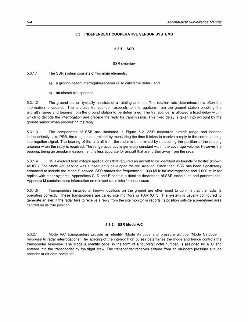
SSR overview 5.3.1.1 The SSR system consists of two main elements: a) a ground-based interrogator/receiver (also called the radar); and b) an aircraft transponder. 5.3.1.2 The ground station typically consists of a rotating antenna. The rotation rate determines how often the information is updated. The aircraft’s transponder responds to interrogations from the ground station enabling the aircraft’s range and bearing from the ground station to be determined. The transponder is allowed a fixed delay within which to decode the interrogation and prepare the reply for transmission. This fixed delay is taken into account by the ground sensor when processing the reply. 5.3.1.3 The components of SSR are illustrated in Figure 5-2. SSR measures aircraft range and bearing independently. Like PSR, the range is determined by measuring the time it takes to receive a reply to the corresponding interrogation signal. The bearing of the aircraft from the radar is determined by measuring the position of the rotating antenna when the reply is received. The range accuracy is generally constant within the coverage volume. However the bearing, being an angular measurement, is less accurate for aircraft that are further away from the radar. 5.3.1.4 SSR evolved from military applications that required an aircraft to be identified as friendly or hostile (known as IFF). The Mode A/C service was subsequently developed for civil aviation. Since then, SSR has been significantly enhanced to include the Mode S service. SSR shares the frequencies 1 030 MHz for interrogations and 1 090 MHz for replies with other systems. Appendices C, D and E contain a detailed description of SSR techniques and performance. Appendix M contains more information on relevant radio interference issues. 5.3.1.5 Transponders installed at known locations on the ground are often used to confirm that the radar is operating correctly. These transponders are called site monitors or PARROTS. The system is usually configured to generate an alert if the radar fails to receive a reply from the site monitor or reports its position outside a predefined area centred on its true position.
5.3.2 SSR Mode A/C 5.3.2.1 Mode A/C transponders provide an identity (Mode A) code and pressure altitude (Mode C) code in response to radar interrogations. The spacing of the interrogation pulses determines the mode and hence controls the transponder response. The Mode A identity code, in the form of a four-digit octal number, is assigned by ATC and entered into the transponder by the flight crew. The transponder receives altitude from an on-board pressure altitude encoder or air data computer.

Chapter 5. Air-Ground Surveillance Systems 5-5
Figure 5-2. SSR
SSR Mode A/C characteristics 5.3.2.2 The capabilities of the SSR Mode A/C system include: a) determination of target’s identity and pressure altitude, in addition to range and bearing; b) signalling emergencies such as loss of radio communications or unlawful interference by the selection
of special Mode A codes reserved for these purposes; and c) long-range coverage since the interrogation and reply signals only need to overcome the one-way
path loss between the transmitter and the receiver. 5.3.2.3 The limitations of SSR Mode A/C systems are: a) aircraft have to be equipped with a functioning transponder; b) there are no problems detecting a number of closely spaced targets because of overlapping replies; c) there is no inherent method of detecting data errors in interrogation or reply signals; d) limited airborne information (identity and altitude) can be downlinked; and e) accuracy is limited by the transponder delay tolerance, thus it is not useable for aerodrome
surveillance. 5.3.2.4 On the basis of SSR data provided to the radar processing systems, aircraft ground speed, vertical speed and predicted future can be calculated.
XYZ 456FL 300
ABC 123FL 280
ATC display systemTranspo
nder reply
(1 09
0 MHz)
Interro
gation (1 0
30 Mhz)
Surveillancedata
processor
Aircraftreports

5-6 Aeronautical Surveillance Manual
5.3.3 SSR Mode S
SSR Mode S overview 5.3.3.1 Mode S allows selective addressing of aircraft through the use of a 24-bit aircraft address that uniquely identifies each aircraft and has a two-way data link between the ground station and aircraft for the exchange of information. It was designed to be backward compatible with and supports all functions of Mode A/C. Appendix F shows details of Mode S and Mode A/C compatibility. 5.3.3.2 The Mode S data link allows additional information such as airspeed, heading, ground speed, track angle, track angle rate vertical rate and roll angle to be obtained from the aircraft. Such aircraft derived data may be used to improve the tracking of the aircraft and to alleviate the need for radio calls for obtaining the information. Other information that may be obtained via the Mode S data link includes the aircraft ID, the altitude selected by the flight crew on the aircraft’s mode control panel and an ACAS RA report. Appendix I shows details of Mode S specific services. 5.3.3.3 In parts of Europe, there have been mandates issued requiring all aircraft that fly into designated airspace to be equipped with a Mode S transponder capable of supplying aircraft derived data. These requirements are known as ELS and EHS; mandates have been introduced in Chapter 2. 5.3.3.4 The Mode S data link also allows information to be uplinked or sent from the radar to aircraft. This uplink is used in a function known as TIS where an aircraft is provided, upon request, information on the aircraft detected by the radar to be in its vicinity. Appendices G, H and J contain detailed descriptions of Mode S protocols and implementation considerations.
SSR Mode S characteristics 5.3.3.5 The capabilities of SSR Mode S system include: a) accommodation of Mode A/C capabilities; b) reporting of pressure altitude in either 100-ft or 25-ft increments; c) selective interrogation of aircraft eliminating interference between closely spaced aircraft resulting in
high probability of message decoding in high density traffic; d) protection against transmission errors by a CRC to ensure data integrity; and e) provision of a two-way data link between the aircraft and ground that can be used to obtain aircraft
derived data. 5.3.3.6 The implementation of SSR Mode S systems requires: a) aircraft to be equipped with a functioning Mode S transponder; b) proper configuration of aircraft installation (e.g. allocation and configuration of a 24-bit aircraft address,
and interface with other aircraft systems); and c) assignment of ICs and adequate management of ground installations in areas with overlapping Mode
S interrogator coverage.

Chapter 5. Air-Ground Surveillance Systems 5-7
5.3.4 Radar antenna configurations
Combined PSR and SSR 5.3.4.1 Typically, the PSR antenna and the SSR antenna are mounted on the same turning gear to ensure simultaneous detection and to reduce cost. The associated processing combines the PSR and SSR data to produce one track for each aircraft. 5.3.4.2 PSR provides detection of aircraft in the absence of a functioning transponder, and SSR detects transponder-equipped aircraft as well as providing altitude and identity information. The availability of PSR and SSR information allows resolution of tracking ambiguities that can exist in each system. In the case of Mode S radar additional information may be obtained from the aircraft. 5.3.4.3 Some installations have PSR and SSR systems at separate locations. This has the advantage of providing a level of redundancy because if one antenna stops rotating, a reduced level of service can be provided from the other. However, in this case the advantages of improved tracking performance are compromised. Also, this arrangement comes at a greater cost when compared to the collocated configuration. 5.3.4.4 Combined PSR and SSR radars are usually provided to support approach/departure services in terminal areas. The primary radar provides the protection of detecting aircraft without an operating transponder that stray into controlled airspace in the busy terminal area, while the information from the secondary radar is usually used to provide separation services.
SSR with electronically steered antenna 5.3.4.5 Electronically scanned (e-scan) antenna radars use an array of stationary radiating elements to produce an electronically steered beam. E-scan radars are able to produce a highly focused beam (yielding higher bearing accuracy) and a higher scan rate (e.g. once a second) to support more demanding applications. 5.3.4.6 One such application is the tracking aircraft on approach to closely spaced parallel runways. The objective is to detect divergence from the defined final approach path. It operates as an SSR interrogating aircraft on the approach path at a high rate, while also performing a background scan in a 360-degree azimuth at a lower rate to acquire aircraft that enter the coverage area.
5.3.5 MLAT
MLAT overview 5.3.5.1 An MLAT relies on signals from an aircraft’s transponder being detected at a number of receiving stations. MLAT uses a technique known as TDOA to establish surfaces that represent constant differences in distance between the target and pairs of receiving stations. The aircraft position is determined by the intersection of these surfaces. 5.3.5.2 Multilateration can theoretically be performed using any signals transmitted periodically from an aircraft. However, systems used for civil purposes are based only on SSR transponder signals. An MLAT requires a minimum of four receiving stations to calculate an aircraft’s position. If the aircraft’s pressure altitude is known then the position may be resolved using three receiving stations. However, in practice, operational MLATs have many more receiving stations to ensure adequate coverage and performance.

5-8 Aeronautical Surveillance Manual
5.3.5.3 The accuracy of an MLAT is non-linear within the coverage volume. It is dependent on the geometry of the target in relation to the receiving stations and the accuracy to which the relative time of receipt of the signal at each station can be determined. A schematic diagram of an MLAT is shown in Figure 5-3.
Time reference requirement 5.3.5.4 An MLAT needs a common time reference to determine the relative TOA of the signal at the receiving stations. This is normally done in one of two ways: a) all the received signals are sent to a central processing station where they are time-stamped by a
common clock. In this case, the system must determine and make allowance for the message transit time between each receiving station and the central station. The system transmits messages between the central and receiver stations to monitor and adjust the transit time; or
b) the clocks in all of the receivers are kept in synchronism by a common reference such as GNSS, or
through the use of a transmitter at a known location. The distance between this transmitter and the receiving stations is known, and by monitoring the time of receipt of the signals from this transmitter at each receiving station, adjustments can be made to ensure the receiver clocks remain synchronized.
Interrogation capability 5.3.5.5 MLATs may include transmitting stations capable of interrogating aircraft transponders. This may be necessary if there are no other interrogations in the coverage area of the system to generate SSR reply signals. It may also be necessary to obtain Mode A code, pressure altitude and possibly other (through Mode S replies) aircraft data. Some systems also use the interrogations and subsequent replies to measure the range of the aircraft from the transmitting station in a similar manner to radar. This range measurement supplements the multilateration TDOA information.
Use of ES transmissions 5.3.5.6 MLATs can process ES signals in two ways: a) by using TDOA, as with all other transponder signals; and b) by decoding the message content to determine the aircraft’s position (latitude and longitude), pressure
altitude and velocity. MLAT therefore provides a transition to an environment where the majority of aircraft will be equipped with ADS-B.
Applications 5.3.5.7 Multilateration may be used for airport surface, terminal area and en-route surveillance. Its use for surface surveillance applications relies on aircraft transponders being active while being on the ground. In many aircraft, the transponder’s operation is controlled by the weight-on-wheels switch, also known as the squat switch. Mode S transponders continue to transmit squitters and may be selectively interrogated while they are on the ground. However, Mode A/C transponders are often inhibited from replying to interrogations while the aircraft is on the ground to reduce the impact on nearby radar systems.

Chapter 5. Air-Ground Surveillance Systems 5-9
Figure 5-3. MLAT
Characteristics 5.3.5.8 The capabilities of multilateration include: a) the use of any signals (Mode A/C, Mode S replies and squitters) transmitted by existing transponders
without requiring additional aircraft equipage to locate aircraft; b) Mode A/C, Mode S and ADS-B capabilities; c) provision of coverage in difficult terrain. It is a modular system in that the coverage area may be
extended by the addition of more stations, provided that the total number of stations remains within the processing capability of the system; and
d) provisions of high accuracy and high update rates. The system accuracy may also be controlled to
some extent by the placement of the receiving stations.
ATC display system
4
3
2
1
Groundcommunications
network
Multilaterationstation
Transponder reply or Mode S squitter
Transponder reply may bereply to interrogatin frommultilateration system orreply to SSR interrogation(Mode A, C or S)
Calculated surfaces ofconstant time difference
Surveillancedata
processor
Multilaterationprocessing
station
Aircraftreports
ABC 123FL 200

5-10 Aeronautical Surveillance Manual
5.3.5.9 The limitations of multilateration are: a) aircraft have to be equipped with a functioning transponder; b) the transmitted signal has to be correctly detected at multiple receiving stations. This may present
problems finding suitable sites for receivers, especially in en-route applications; and c) communication links are needed between remote receiver/transmitter sites and the master processing
station. Appendix L contains guidance material on MLATs.
5.4 DEPENDENT COOPERATIVE SYSTEMS
5.4.1 ADS-C
ADS-C overview 5.4.1.1 In ADS-C the aircraft uses on-board navigation systems to determine its position, velocity and other data. A ground ATM system establishes a “contract” with the aircraft to report this information at regular intervals or when defined events occur. This information is transmitted on point-to-point data links. This means the information cannot be accessed by other parties (i.e. other aircraft or other ATM systems). The aircraft operator and ATM provider each establish agreements with a data link service provider for delivery of the ADS-C messages. 5.4.1.2 Information that may be transmitted in ADS-C reports includes: a) present position (latitude, longitude and altitude) plus time stamp and FOM; b) predicted route in terms of next and (next +1) waypoints; c) velocity (ground or air referenced); and d) meteorological data (wind speed, wind direction and temperature). 5.4.1.3 The airborne and ground systems negotiate the conditions under which the aircraft submits reports (i.e. periodic reports, event reports demand reports and emergency reports). Reports received by the ATM system are processed to track the aircraft on displays in a way similar to surveillance data obtained from SSR. The reporting rate for current oceanic operations is normally about 15 to 25 minutes. It is however possible for controllers to manually increase the reporting rate to support specific operations. A schematic diagram of ADS-C is shown in Figure 5-4.
Applications 5.4.1.4 ADS-C is typically used in oceanic and remote areas where there is no radar. As a result, it is mainly fitted to long-range air transport aircraft and could support more efficient separation standards than in a case where ATC is reliant only on pilot reports. ADS-C is usually used in conjunction with CPDLC, which allows electronic data communication between ATC and flight crew as an alternative to voice communications. Note.— ADS-C is currently used entirely to provide procedural separation.

Chapter 5. Air-Ground Surveillance Systems 5-11
Figure 5-4. ADS-C
Characteristics 5.4.1.5 The capabilities of ADS-C are: a) provision of surveillance in areas where the installation of radar or MLATs is not practical; b) allows practical reporting of aircraft intent data (e.g. future waypoints), which is useful in determining
potential conflicts; and c) provision of a data link between the aircraft and ground, allowing relevant aircraft data to be sent to
controllers. 5.4.1.6 The limitations of ADS-C are: a) it is a dependent surveillance system, i.e. it relies on the aircraft being suitably equipped to correctly
transmit the data; b) it requires the installation of additional avionics (for data communications);
XYZ 456FL 300
ABC 123FL 280
Surveillancedata
processor
Satellitegroundstation
VHF Datalink ground
station
Aircraft reports and ADS-Cmanagement messages
Messages are deliveredby ARINC or SITA usingsatellite or VHF data link
Aircraft uses a combinationof GNSS and inertial navigation
sensors to determine its position.Position is then sent in ADS-C messages
Communicationssatellite
GNSS
ADS-Cmessages
ADS-Cmessageprocessor
ATC display system

5-12 Aeronautical Surveillance Manual
c) performance may be determined by the limitations of the communications media; d) a cost may be associated with the transmission of each report since the data is carried by a data link
service provider. As a result, the update rate is usually kept low to reduce costs; and e) it does not support ASA because the messages are not directly available to other aircraft.
5.4.2 ADS-B
ADS-B overview 5.4.2.1 ADS-B is the broadcast by an aircraft of its position (latitude and longitude), altitude, velocity, aircraft ID and other information obtained from on-board systems. Every ADS-B position message includes an indication of the quality of the data which allows users to determine whether the data is good enough to support the intended function. 5.4.2.2 The aircraft position, velocity and associated data quality indicators are usually obtained from an on-board GNSS. Current inertial sensors by themselves do not provide the required accuracy or integrity data, although future systems are likely to address this shortcoming. ADS-B position messages from an inertial system are therefore usually transmitted with a declaration of unknown accuracy or integrity. Some new aircraft installations use an integrated GNSS and inertial navigation system to provide position, velocity and data quality indicators for the ADS-B transmission. These systems are expected to have better performance than a system based solely on GNSS, since inertial and GNSS sensors have complementary characteristics that mitigate the weaknesses of each system. Altitude is usually obtained from the pressure altitude encoder (also used as the data source for Mode C replies). 5.4.2.3 Since ADS-B messages are broadcast, they can be received and processed by any suitable receiver. As a result, ADS-B supports both ground-based and airborne surveillance applications. For aeronautical surveillance, ground stations are deployed to receive and process the ADS-B messages. In airborne applications, aircraft equipped with ADS-B receivers can process the messages from other aircraft to determine the location of surrounding traffic in support of applications such as the CDTI. Other, more advanced ASAs are under development and are expected to have a significant impact on the way in which air traffic is managed. A schematic diagram of ADS-B is shown in Figure 5-5. 5.4.2.4 Three ADS-B data links (or signal transmission systems) have been developed and standardized, and are described in the following sections.
Mode S 1 090 MHz ES (1 090 ES) 5.4.2.5 As the name suggests, 1 090 ES was developed as part of the Mode S system. The standard Mode S acquisition squitter is 56 bits long. The 1 090 MHz ES contains an additional 56-bit data block containing ADS-B information. Each ES message is 120 microseconds long (8 microseconds of preamble and 12 microseconds of data). The signals are transmitted at a frequency of 1 090 MHz, and have a data transmission rate of 1 Mbps. The ADS-B information is broadcast in separate messages, each of which contains a related set of information (e.g. airborne position and pressure altitude, surface position, velocity, aircraft ID and type, emergency information). Position and velocity are transmitted twice per second. Aircraft ID is transmitted every 5 seconds. The transmission of ES ADS-B is an integral part of many Mode S transponders, although it may also be implemented in a non-Mode S transponder device as well.

Chapter 5. Air-Ground Surveillance Systems 5-13
Figure 5-5. ADS-B
5.4.2.6 There is international agreement that Mode S ES will be used for air transport aircraft worldwide to support interoperability, at least for initial implementation. The manual on Technical Provisions for Mode S Services and Extended Squitter (Doc 9871) contains details on Mode S ES.
UAT 5.4.2.7 UAT has been designed as a general purpose aviation data link to allow uplink of information in addition to the transmission of ADS-B data. It operates at a frequency of 978 MHz and has a signalling rate of 1 Mbps, like the Mode S ES. Each UAT transceiver is allocated a time slot or channel called an MSO within which it can transmit information. Channels may be allocated in one of two segments: the ADS-B segment and the ground segment. Channels in the ADS-B segment are 250 microseconds long and are allocated to aircraft for transmission of ADS-B data. Channels in the ground segment are reserved for the broadcast of weather and flight information by the ground system, a service known as FIS. These channels are each 5.5 milliseconds (22 MSOs) long.
Surveillancedata
processor
ADS-BGROUNDSTATION
Aircraftreports
ATC display system
ADS-B messages
Aircraft uses GNSSand/or inertial navigationsensors to determine its
position
XYZ 456FL 300
ABC 123FL 280
GNSS

5-14 Aeronautical Surveillance Manual
5.4.2.8 Since each UAT transceiver is allocated a time slot, the receiver is able to perform a range check, based on the time of receipt of the message, to provide a rudimentary validation of the broadcast position. This feature also allows aircraft receiving TIS-B messages to determine their range from the ground station. The Manual on the Universal Access Transceiver (UAT) (Doc 9861) contains details of UAT.
VHF digital link Mode 4 (VDL Mode 4) 5.4.2.9 VDL Mode 4 was developed as a generic data link supporting CNS functions. The applicability was initially restricted to surveillance applications like ADS-C and ADS-B, but the regulatory restrictions were later removed so that VDL Mode 4 is now available as a CNS data link. The system supports broadcast and point-to-point communications for air-ground and air-air applications. VDL Mode 4 is a narrow-band system operating on multiple 25 kHz channels in the VHF band (108–137 MHz). Access to the channels is synchronized to UTC and based on a self-organizing TDMA scheme that allows all communicating units to select free slots for transmissions. A number of protocols are available in support of the various modes of communication. The Manual on VHF Digital Link (VDL) Mode 4 (Doc 9816) contains details of the VDL Mode 4.
5.4.3 Characteristics 5.4.3.1 The capabilities of ADS-B are: a) the ground station is simpler than the stations of primary radar, secondary radar and multilateration.
For a single ADS-B site, acquisition and installation costs are significantly lower. In many instances, the installation can be accommodated at navigation aid sites or sites such as VHF radios with existing infrastructure;
b) each position report is transmitted with an indication of the integrity associated with the data, allowing
users to determine which applications the data can support; and c) supports both ground-based and airborne surveillance applications. 5.4.3.2 The limitations of ADS-B are: a) it depends on proper equipage of all aircraft. This could be a significant issue because a navigation
source capable of supplying position/velocity information along with the necessary indication of accuracy/integrity of that information needs to be installed and certified;
b) current implementations rely solely on GNSS for position and velocity. As a result, outages may be
experienced when the performance or geometry of the satellite constellation is inadequate to support a given application. Future systems that integrate GNSS information with data from other navigation sensors should overcome this limitation. Also the advent of GALILEO should improve GNSS performance; and
c) provisions should be in place to validate the reported position.

Chapter 5. Air-Ground Surveillance Systems 5-15
5.5 SDP SYSTEMS
5.5.1 Aircraft tracking techniques 5.5.1.1 Aeronautical surveillance systems often include a number of sources (e.g. PSR, SSR and ADS-B), each of which provides data to a processing system. Once aircraft information is received from the various sensors, it needs to be processed by SDP systems and passed onto the display systems used by air traffic controllers. 5.5.1.2 A number of aircraft tracking schemes are used in SDP systems, including mosaic tracking, track fusion and position report fusion systems which are described in 5.5.2 to 5.5.4 below.
5.5.2 Mosaic tracking systems In a basic mosaic system, the airspace is divided into cells, and a single source will typically provide surveillance data for each cell. The surveillance processing system receives data from all sources and applies the relevant data depending on which cell the aircraft is detected in.
5.5.3 Track fusion systems In track fusion systems, the SDP system accepts tracks and applies a weighting to each track to produce a track position for the target at each update. The weighting considers the accuracy of each source at the target location and the age of each position report from the various sources.
5.5.4 Position report fusion systems 5.5.4.1 In position report fusion systems, the processing system accepts position updates from each source and combines the data to establish the best estimate of the target’s position. It then generates a track of the target based on successive fused position reports. 5.5.4.2 Fusion systems generally provide the best performance but are more complicated. They have to take into account the different characteristics of the surveillance sources, and the fact that position reports are likely to arrive asynchronously.
5.6 SURVEILLANCE DATA DISTRIBUTION BY ASTERIX
5.6.1 Overview 5.6.1.1 The ASTERIX specifications were developed in Europe in order to harmonize the transmission of surveillance information. ASTERIX specifications describe formats for the exchange of data between the surveillance sensors and data processing systems, and also for the generalized exchange of surveillance data between systems.

5-16 Aeronautical Surveillance Manual
5.6.1.2 ASTERIX has provision for sending different categories of information. The categories are roughly aligned to the different types of sensors, although some categories allow data from several types of sensors to be merged. For each category, the specification defines all the possible data fields that may be transmitted. ASTERIX is efficient in that only the fields that contain current data need to be transmitted. The specification defines the message field content and formats. The messages may be transmitted using any suitable data transport mechanisms such as UDP or TCP. The current set of ASTERIX documents includes categories for the transmission of radar, multilateration, ADS-B and integrated surveillance data.
5.6.2 Addressing scheme ASTERIX contains an addressing scheme to identify the source providing the data. It comprises the SAC and the SIC. Appendix N contains more details on ASTERIX.
______________________

6-1
Chapter 6
AIRBORNE SURVEILLANCE
6.1 INTRODUCTION 6.1.1 Surveillance systems have initially been deployed in such a way that the display of traffic has been on the ground for ATM purposes. The evolution of the technology now allows the provision of surveillance capability and display of traffic on board aircraft, known as airborne surveillance. 6.1.2 The capability to establish a complete air situation picture on board aircraft allows the development of new applications that are presently under development, for example: a) merging and sequencing, which enables controllers to instruct flight crew to use their flight deck
surveillance systems to follow another specified aircraft; and b) the in-trail procedure, which enables an aircraft on oceanic routes to climb (or descend) through a
flight level that would otherwise be blocked by the procedural separation minima and the proximity of other aircraft.
6.2 ADS-B IN ADS-B IN is an airborne function that receives surveillance data transmitted by ADS-B OUT functions installed on other aircraft. In addition, it could also receive, from the ground, additional data from other aircraft not transmitting ADS-B OUT (see 6.3, TIS-B) or because their ADS-B OUT is transmitted using a different ADS-B technology (see 6.4, ADS-B rebroadcast).
6.3 TIS-B 6.3.1 TIS-B is the broadcast of aircraft surveillance data by ground stations using an ADS-B data link. The information is used by flight crews to obtain a picture of air traffic in their vicinity, including those aircraft that are not ADS-B equipped. This provides improved situational awareness and support for ASA. 6.3.2 TIS-B ground stations obtain aircraft surveillance data from a number of sources including SSR and MLATs. The TIS-B ground station does not generate messages for aircraft broadcasting ADS-B on the same data link, since this may be obtained directly from the aircraft. 6.3.3 TIS-B provides service in an environment where not all aircraft are equipped with ADS-B. It provides visibility of non-ADS-B equipped aircraft to any aircraft capable of receiving the TIS-B message. TIS-B messages are similar in format to ADS-B messages transmitted directly by aircraft. A schematic diagram of TIS-B is shown in Figure 6-1.

6-2 Aeronautical Surveillance Manual
Figure 6-1. TIS-B
6.4 ADS-R ADS-R allows interoperability between ADS-B equipped aircraft operating on different data links. The ADS-R ground station receives ADS-B messages from one link (e.g. UAT), processes the messages and rebroadcasts them on a different data link (e.g. 1 090 MHz ES). Docs 9861 and 9871 contain details of TIS-B and ADS-R.
6.5 ACAS
6.5.1 Overview ACAS interrogates Mode A/C and Mode S transponders on aircraft in its vicinity and listens for their replies. By processing these replies, ACAS determines which aircraft represent potential collision threats and provides appropriate indications (or advisories) to the flight crew to avoid collisions.
ABC123
Transponder reply(1 090 MHz)
Interrogation(1 030 MHz)
SSRstation
TIS-Bgroundstation
TIS-B messagefor aircraftABC123
ABC 123FL 080

Chapter 6. Airborne Surveillance 6-3
6.5.2 Operation ACAS interrogates Mode A/C aircraft by transmitting a special Mode S signal that elicits Mode C replies from Mode A/C aircraft but no replies from a Mode S aircraft. ACAS detects the presence of Mode S-equipped aircraft by receiving their acquisition squitters and by monitoring surveillance replies to ground interrogations, and it then interrogates those aircraft using the acquired 24-bit address.
6.5.3 Hybrid surveillance This technique allows ACAS to take advantage of information passively available from ADS-B OUT transmissions of suitably equipped extended aircraft. At acquisition and periodically thereafter, ACAS validates the position and altitude contained in the ES with information received from its own active surveillance. Aircraft whose position and altitude are validated can be maintained on passive surveillance, resulting in reduced ACAS interrogations. Passive surveillance is only used on aircraft that are not considered to be a threat. When an intruder approaches the conditions for a threat, ACAS switches to full active surveillance.
6.5.4 Future ACAS Research is under way to investigate the role of and requirements for collision avoidance in the future as aircraft densities increase, and new aircraft types and capacity-enhancing operations are introduced. Collision avoidance will likely utilize additional data from new surveillance sources. The data may include velocity and intent information as well as improved position accuracy. Enhanced algorithms will be needed to take advantage of the improved surveillance. A primary concern will be to maintain compatibility with operations and minimize disruptive effects such as nuisance alerts. The Airborne Collision Avoidance System (ACAS) Manual (Doc 9863) contains a complete set of guidance material on ACAS.
6.6 DISPLAYS FOR AIRBORNE SURVEILLANCE 6.6.1 The most basic ASA enabled by ADS-B is the enhanced ATSAW using CDTI. This application consists of displaying surrounding traffic with appropriate symbols. 6.6.2 At present, the ACAS display provides similar but limited information. As shown in Figure 6-2, in a traffic situation generated with ACAS surveillance, the range is limited to less than 30 NM, and there is neither identification nor heading information. Typical examples of the traffic situation using simulated data are shown in Figures 6-2 to 6-4. However, using the information contained in the received ADS-B messages, it is possible to elaborate a traffic situation on an integrated display using new symbols supporting heading information, identification and speed. 6.6.3 Figure 6-3 shows the same traffic as in Figure 6-2 with additional information as well as traffic outside the ACAS surveillance range. It is clear that own aircraft is being merged into the sequence of descending aircraft. This information could certainly increase the traffic situational awareness of the flight crew. 6.6.4 Another example is shown in Figure 6-4. The figure that involves merging and sequencing shows how a specified aircraft (AFR3141) designated by the controller could be followed accurately 90 seconds behind, thanks to a tracking process based on ADS-B information provided to own aircraft. In the example, the magenta dot represents the position of the specified aircraft 90 seconds before. Any other traffic may be removed from the display to avoid clutter or misunderstandings for the flight crew following the procedure. The box on the left shows the relative distance in NM between own aircraft and the reference aircraft as well as the air speed.

6-4 Aeronautical Surveillance Manual
Figure 6-2. Example with ACAS symbols integrated into the navigation display

Chapter 6. Airborne Surveillance 6-5
Figure 6-3. Example of same traffic as in Figure 6-2 with new symbols supported
by ADS-B without operational ACAS

6-6 Aeronautical Surveillance Manual
Figure 6-4. Example of a possible future ASA application
on an integrated display
______________________

7-1
Chapter 7
SURVEILLANCE SYSTEM DEPLOYMENT CONSIDERATIONS
7.1 BEST PRACTICES CHECKLIST The following list shows steps recommended for planning and implementation of surveillance systems (including replacement or upgrade of existing facilities): a) Define the operational requirements: • Select applications to be supported: This will allow the determination of the necessary
performance. • Define area of coverage: The determination of the volume in which the operational service will be
supported is very important because it will drive the cost of the system. In particular, the correct determination of the lower altitude limits is very important as it will have a significant impact on the number of sensors to be deployed;
• Define the type of traffic: for example, FR flights, VFR flights, local or international flights, civil or
military flights. b) Define local environment (current and future): • Current and expected future traffic densities including the description of possible peak times; • Route structure; • Type of airborne equipage currently mandated for the different types of flights (carriage mandate
and real rate of equipage); • Type of aircraft: commercial, general aviation, helicopters, gliders, ultra light aircraft, VLJ, military
and their dynamic characteristics (maximum speed, climbing rate, turn rate, etc.); • Segregation between the different types of traffic, the possible mix of traffic and the probability of
intrusion of aircraft not equipped with cooperative surveillance means; • Specific local RF environment. c) Analyse design options and determine which techniques can be used: • Check which existing surveillance sensors may be re-used; • Check which new surveillance sensors and techniques may be deployed at lowest cost. • Determine the number of sites and investigate their availability. Verify airborne equipage;

7-2 Aeronautical Surveillance Manual
• Determine the level of redundancy required and fall-back mode of operation; • Determine whether new airborne equipment carriage will be necessary; • Determine impact on operational procedure; • Conduct cost-benefit studies and feasibility analyses for the different options if necessary. d) Make a safety analysis of the new proposed system: • To demonstrate that the system will provide the necessary performance in its nominal mode of
operation; • To demonstrate that the different failures have been analysed; • To demonstrate that they have been found to be either acceptable or can be mitigated. e) Implement: • If new airborne equipment is required, then prepare airborne carriage mandate; • Procure and install the new system; • Evaluate the performance of the new system. f) Establish operational service: • Transition from existing system to the new system. g) Deliver operational service: • Periodically verify the performance of the new system; • Conduct regular and preventive maintenance.
7.2 TRANSITION TO DEPENDENT SURVEILLANCE SYSTEMS 7.2.1 Any new surveillance technique being considered as a replacement for an existing surveillance system must provide at least the same level of performance required by the existing applications. Technical surveillance system performance requirements are under development to help with the specification of the needs of an application. 7.2.2 In addition to accuracy, availability, reliability, integrity and update rate, the new surveillance system must be as robust as currently required by the existing system that is being replaced. During the period of transition to a new surveillance system, the following points should be considered: a) an adequate level of protection against common mode failures should be provided; b) a fallback surveillance system and/or some operational procedures to accommodate the loss of the
GNSS function in an individual aircraft (e.g. due to an equipment malfunction) would be required;

Chapter 7. Surveillance System Deployment Considerations 7-3
c) similarly, the possibility of the loss of the GNSS function over an extended area (e.g. due to interference effects on GNSS operation) should be taken into account;
d) validation (or at least a reasonableness test) of the reported ADS-B position is needed to reduce the
probability of an operationally significant undetected failure on board the navigation data source; e) in operational environments, where the threat to safety is of significant concern, it should be possible
to detect and suppress the creation of tracks on ADS-B reports that contain intentionally incorrect position information; and
f) measures should be in place to cope with the expected growth in traffic over the planned life of the
system. 7.2.3 The operational use of ADS-B without the aforementioned precautions and safeguards would not be advisable. In general, the performance of a surveillance system for a given area and an operational scenario should be specified by the responsible authority. Depending upon the particular airspace and the application, this may imply the need to continue to retain a certain level of SSR operation during the transition period.
7.3 OTHER ISSUES Other issues to be considered when designing a surveillance system are: a) the need to identify the source of surveillance when information is displayed. This may be necessary if
the type or condition of the source affects procedures; b) the ability to uniquely identify targets; c) the impact of the loss of surveillance of individual aircraft, both in the short and long term; d) the impact of the loss of surveillance over an extended area; e) backup or emergency procedures to be applied in the event of aircraft or ground system failure; f) the ability to operate to specification with the expected traffic density; g) the ability to operate in harmony with other systems such as ACAS and ASA; and h) the interaction between CNS functions.
______________________


A-1
Appendix A
TECHNICAL PERFORMANCE REQUIREMENTS
1. SCOPE
1.1 Objectives 1.1.1 In general, technical performance requirements should be independent of technology and architecture used in a surveillance system that supports a particular ATS service or function (referred to as an application in this document). 1.1.2 Performance requirements are useful for: a) system design and derivation of requirements for various different components of the surveillance
system; b) safety assessment; c) procurement; d) commissioning; and e) monitoring of performance. As such, the performance requirements should be measurable and verifiable, and also defined for specific applications.
1.2 Need for performance requirements 1.2.1 Traditionally, surveillance systems have been specified by a set of performance criteria such as probability of detection, accuracy, refresh rate, latency, integrity and availability. These specifications have the following limitations: a) such criteria are generally sensor-oriented. For example, an accuracy expressed in a polar system of
coordinates (range and azimuth) is logical for radar but is not necessary for other surveillance techniques;
b) some requirements seem to have been only driven by the state-of-the-art technology used (e.g. an
accuracy of 15 m being specified for current Mode S radars); and c) some basic requirements may be missed as they are relevant only to one specific technology. There is therefore a need to define objective performance requirements applicable to surveillance systems using different or combinations of techniques supporting various applications. It should also be noted that new applications are

A-2 Aeronautical Surveillance Manual
being defined for which specific performance may be required. Moreover, some of these new applications may impose additional requirements on the airborne part of the surveillance system, and therefore, a common way of defining surveillance performances would be desirable. 1.2.2 Any changes in technical systems supporting ATM should be subject to safety analysis. Performance requirements included in this appendix mainly state what the system shall provide when it works in its nominal mode of operation. The requirements can be used as a starting point for the safety analysis.
1.3 Limitations and constraints 1.3.1 The material contained in this appendix should be considered as a minimum set of performance requirements recognized and agreed to as achievable by a surveillance system in order to support a particular application. However, it should be understood that meeting these requirements is not sufficient to prove that an application can be used safely because, in general, there are people, procedures and other systems or equipment involved. The technical performance requirements for surveillance systems are not sufficient to authorize a given operational separation. There are other factors that should be analysed during the safety assessment (e.g. Human Factors, procedures, airspace structure and traffic density). 1.3.2 The material will, however, help aviation authorities in technically specifying, testing, accepting and monitoring the performance of their surveillance system. 1.3.3 One of the challenges in establishing performance requirements is having the means of deriving quantitative and measurable requirements from qualitative ones envisaged, derived or expressed by people. In order to do so, a number of hypotheses are used to simplify the complex interrelationship between the different performance parameters. These limitations should be understood and accepted.
1.4 Scope of surveillance systems 1.4.1 When considering performance requirements, the term “surveillance system” refers to all items in the surveillance chain up to the point of delivery of surveillance data up to the applications that use it. Therefore, no requirements are defined here for the user applications themselves, various HMI subsystems and other tools that may use surveillance data. 1.4.2 With regard to performance requirements, it can be considered that the surveillance system consists of two subsystems separated by an RF link: a) a local surveillance subsystem on the user application side of the RF link; and b) a remote surveillance subsystem on the aircraft side of the RF link. 1.4.3 Three examples of surveillance systems are provided in Figures A-1, A-2 and A-3. Figure A-1 shows a multi-sensor air-ground surveillance system, while Figure A-2 shows a single-radar air-ground surveillance system. Figure A-3 shows an example of ground and airborne use of ADS-B. 1.4.4 Flight plan correlation and other functions like STCA are not included in the scope of the surveillance system.

Appendix A. Technical Performance Requirements A-3
Figure A-1. Multi-sensor air-ground surveillance system
TRANSPONDER
Aircraft data sources
ALTIMETER, PILOT INPUT …
Remote surveillance subsystem
Aircraft surveillance data compilation
Aircraft surveillance data transmission
WAM SSR MODE S
PROCESSOR/TRACKER
Local surveillance subsystem
RF transmission
Ground surveillance sensors/receivers
Ground surveillance data processing
ATC HMI, safety alerting tools, … Surveillance data usersUsers
Scop
e of
sur
veill
ance
sys
tem
ADS-B
ADS-B MODE S MODE A/C

A-4 Aeronautical Surveillance Manual
Figure A-2. Single-radar air-ground surveillance system
TRANSPONDER
ALTIMETER, PILOT INPUT…
AircrafT surveillance data compilation
Aircraft surveillance data transmission
SSR
ATC HMI, safety alerting function…
Mode A/C
PROCESSOR/TRACKER
Ground surveillance sensors/receivers
Ground surveillance data processing
Surveillance data usersUsers
Local surveillance subsystem
RF transmission
Remote surveillance subsystem
Aircraft data sources
Scop
e of s
urve
illan
ce s
yste
m

Appendix A. Technical Performance Requirements A-5
Figure A-3. Example of ADS-B surveillance system
Airc
raft
surv
eillan
ce d
ata
comp
ilatio
n
Airc
raft
local
surv
eillan
ce su
bsys
tem
Tran
smit
grou
nd d
omain
= re
mote
subs
yste
mGr
ound
loca
l sur
veilla
nce
subs
yste
m
Airc
raft
rem
ote
surv
eillan
ce su
bsys
tem
SSR
Mode
S
AD
S-B
ADS-
B
SSR
WAM
Mod
e S
Surv
eillan
ce d
ata
proc
essin
g
Surv
eillan
ce d
ata
proc
essin
g
ADS-
BTI
S-B
TIS-
B
Grou
nd s
urve
illanc
e da
ta co
mpila
tion
Air-g
roun
dsu
rveil
lance
syste
m
Perfo
rman
cem
easu
rem
ent
point
Perfo
rman
cem
easu
rem
ent
point
Air-A
irsu
rveil
lance
syste
m
Othe
r dat
a so
urce
s
Airb
orne
loca
l use
rs (c
ockp
it disp
lay, .
..)
Data
sour
ces (
FMS,
bar
o-alt
imet
er, G
NSS
rece
iver,
cont
rol p
anel
...)
Grou
nd lo
cal u
sers
(A
TCO
HMI,
safe
ty ne
ts ...
)

A-6 Aeronautical Surveillance Manual
1.5 Quality of service 1.5.1 The set of parameters and associated definitions used to specify performance includes: a) Data item: the information (e.g. position, identity and intent) that the surveillance system is required to
deliver; b) Accuracy: the degree of conformance between the estimated or measured value and the true value of
a data item. The accuracy is defined at the time the value is used. “Error” is used to represent the difference between the measured value and the actual value, while accuracy is used to represent the statistic distribution of the error;
c) Availability: the probability that the system will perform its required function at the initiation of the
intended operation; d) Integrity: the probability that an error of a given amount for a given data item will be undetected by the
system; e) Integrity (system): the probability for a specified period of an undetected failure of a functional element
that results in erroneous surveillance information to the end-user; f) Latency: the difference between the time for which the information is valid and the time it is delivered
to the end-user; g) Update period: the average time difference between two information reports related to the same A/V
and to the same type of information; h) Continuity: the probability that a surveillance system will perform its intended function without
unscheduled interruptions during intended operation; and i) Coverage: the volume of airspace that will be covered by the surveillance system and within which its
performance meets the requirements. j) Reliability: a function of the frequency with which failures occur within the system. The probability that
the system will perform its function within defined performance limits for a specified period under given operating conditions;
1.5.2 Lower-level performance parameters may need to be derived from aforementioned ones. For example, “outage times because of scheduled actions” may be defined as a lower-level parameter that will contribute to the availability of the system. Measures should be put in place to continuously (or periodically on a continuing basis) monitor the performance of the surveillance system in order to ensure that it meets the originally specified requirements.
2. SEPARATION APPLICATION
2.1 General considerations 2.1.1 Content of this part of the document is applicable to cases wherein a surveillance system is used in support of a separation application. In this respect, the following hypotheses have been used to simplify the derivation of quantified performance requirements from operational requirements:

Appendix A. Technical Performance Requirements A-7
a) when two aircraft are flying at a given separation, they are not in a collision situation. Similarly, when two aircraft are seen at the given minimum separation, they will not be closer than a minimum specified buffer at any time during the period of display;
b) the application considered corresponds to a buffer size equivalent to the maximum aircraft size. It
does not cover wake turbulence separation minima for which there may be a need to specify different buffers;
c) the system shall be able to support the display of aircraft trajectories and to distinguish between
aircraft; and d) separation is only provided between identified aircraft. The data items that are generally needed for the provision of separation applications are identified in 2.1.2 to 2.1.5 below. 2.1.2 Horizontal position. This item is the basic information used by most applications. It indicates the location of the aircraft in the horizontal plane. Depending on the type of surveillance system used, the horizontal position information may be supplied as a data item sourced from the remote surveillance subsystem (as in the case of ADS-B) or calculated by the local surveillance subsystem (as in the case of radar and MLATs). The horizontal position information is used by the separation application to ensure a minimum distance between aircraft pairs is not compromised at any time. The horizontal position data supplied to applications can take various forms including: a) range and azimuth (typically provided by radars); b) latitude and longitude (typically provided by an ADS-B system); or c) a specific system of X and Y coordinates (as may be provided by a multi-sensor tracker). 2.1.3 Pressure altitude (also known as barometric altitude). This data item is derived from the altimeter of the aircraft and is used to display the vertical position of aircraft. The local barometric correction has been considered as being outside the surveillance system because it is performed by a user application. 2.1.4 Identity. This data item is obtained by either using the aircraft ID extracted from the aircraft or from its SSR Mode A reply. The identity is used to ensure that ATC instructions are passed to the correct aircraft. The identity extracted from the aircraft by the surveillance system is typically correlated with the flight plan data by the user application. However, this correlation function is considered to be outside the scope of the surveillance system definition. 2.1.5 The data items above are essential for the separation application; however, there are additional data items that offer further benefits where provided: a) SPI — this data item is transmitted at the request of ATC and can be used in the separation
application to provide greater confidence that correct operational identification has been achieved and to quickly locate an aircraft on a surveillance display;
b) ground speed and track — these two data items can be employed by user applications to predict the
future position of aircraft; and c) other surveillance data items such as: 1) sensor type; 2) aircraft derived data, including:

A-8 Aeronautical Surveillance Manual
• magnetic heading • selected altitude • vertical speed • barometric pressure setting 3) time of applicability of the data-items provided for conformity assessment.
2.2 Horizontal error at the end of the update period 2.2.1 In early primary radars, raw video was directly displayed at the controller working position on a PPI display. That system had the following characteristics: a) a very small time delay from detection of a target to its display; b) a clear indication of when the new data was displayed (the rotating radar scan line); and c) an indication of the age of the data through the diminishing intensity of the radar video (blips) on the
PPI. When those systems were used, aircraft separation was considered to be established where blips for two aircraft in close proximity were seen to be separated on the display. 2.2.2 Modern surveillance systems are more complex with many subsystems often combining data from different sources to provide a synthetic representation of the air situation picture on the display. Characteristics in modern systems are: a) there is a time delay from the position measurement to the display (or update thereof); and b) the displayed aircraft positions only change at the time of each synthetic display update. Therefore, the displayed image of the aircraft can be used at any moment without knowing exactly when it had been established. 2.2.3 In most cases, the uncertainty of a displayed position is at its highest just before an update, due mainly to the fact that the subject aircraft has been moving during the update period. As such, the speed of aircraft and the display update rate are significant factors in horizontal position error analysis.
2.3 Errors contributing to the final position uncertainty 2.3.1 The factors that contribute to the total horizontal position error at the surveillance system output can be grouped as follows: a) measurement, quantization and other processing errors directly affecting the positional data; and

Appendix A. Technical Performance Requirements A-9
b) age of the data that leads to an apparent positional error due to the aircraft moving away from the measured position by the time the data are supplied or used.
2.3.2 Figure A-4 shows how these generic sources of error may combine to increase the total horizontal position error. 2.3.3 Generally, measurement, quantization and other processing errors are assumed to be randomly distributed around the real position of the aircraft, Figure A-5 shows how these error distributions could impact aircraft separation. In the figure, the apparent separation is larger than the actual one, but it is possible, due to random distribution of errors as well as due to the movements of aircraft during the update interval, that under worst-case conditions, the two displayed aircraft may be much closer to each other or even overlap. 2.3.4 The horizontal position error at the end of the refresh period is very dependent on the flight characteristics of the displayed aircraft, hence it is difficult to measure and validate. It is more common to measure the error when the data are output from the surveillance system because the performance of the system itself is verified without being impacted by flight characteristics of the subject aircraft.
2.4 Update rate/update period 2.4.1 The term “update rate” is usually used both for the output of the sensor and for the update of the display. In the context of performance, the latter is used with the assumption that the output of the surveillance system is fed directly into the display. Update period depends on local constraints such as type of traffic, maximum climbing rate of aircraft, type of airspace structure, legacy systems and Human Factor considerations. 2.4.2 The update periods chosen for en-route application were initially long (e.g. more than 10 seconds), but with the introduction of newer systems, there is a tendency to use shorter periods. For example, more and more new en-route systems are using an update period of 5 to 6 seconds. 2.4.3 An aircraft is considered to be maintaining its assigned level as long as the pressure-altitude-derived level information that is displayed to the controller indicates that it is within appropriate tolerances of the assigned level (60 m (±200 ft) in RVSM airspace or ±90 m (±300 ft) in other airspace). Similarly, an aircraft is considered to have reached the level to which it has been cleared when the elapsed time of three surveillance update periods, or 15 seconds, whichever is the greater, have passed since the pressure-altitude-derived level information has indicated that it is within the appropriate tolerances of the assigned level. Intervention by a controller shall only be required if the difference between assigned and displayed levels are in excess of the values stated above. If we use the hypothesis that the system must be able to see a 300 ft/200 ft altitude change in one update period, for aircraft climbing or descending at 3 000 ft/min, it means that an update period of 6 seconds (for non-RVSM) and 4 seconds (for RVSM) would be required. 2.4.4 It has not been possible to globally agree on a specific update period. Figure A-6 shows an example of the relationship between horizontal position error and the update period. Section 2.5 provides a method to derive the horizontal position error. Given that an aircraft may cease its climb/descent at any moment, the error of extrapolation of altitude could easily exceed 300 ft/200 ft. For this reason, current surveillance systems output the last measured (extracted) value of the barometric altitude. This could change in the future when newer surveillance systems can access airborne information (such as the barometric pressure) at a high rate.

A-10 Aeronautical Surveillance Manual
Figure A-4. Example of sources of horizontal position error
Surveillancedata
compilation
Data sources
Position error
Surveillancedata
transmission
Surveillancesensor(s)/receiver(s)
Surveillancedata
processing
Surveillance users(HMI, STCA, ...)
Updateperiod/
rate
Remote surveillancesubsystem
Local surveillancesubsystem
RFdata link(s)
(a)
Ref.
(b)
(c)
(d)
Data source measurement
Position error due to ...
Data source to surveillancesystem delay
Remote subsystemprocessing
Remote subsystemdelay
Example
(e) RF link propagation delay
(f)
(g)
(h)
(l)
(j)
(k)
Sensor measurement
Sensor processing delay
Total error sensor output
Ground communication delay
SDP prediction error
SDP and communication delay
(m) Aircraft movingduring update period
(n) <½ separationTotal position error
(l) Total error atbeginning of updateperiod
Real position of aircraft
Measured or calculated position
Measurement, quantization or other processing error
Error due to aircraft movement during delay

Appendix A. Technical Performance Requirements A-11
Figure A-5. Actual and apparent separation between two aircraft
2.5 Determination of horizontal position error during the update period
2.5.1 Choice of operational scenario. In the following exercise, it is assumed (as the worst case scenario that is rather unlikely in practice) that two aircraft are on the same altitude and are “heading-on” at the maximum speed. 2.5.2 Calculation of a buffer to cover displacement during update period. The parameters used to calculate the remaining horizontal budget at the moment the data are output from the surveillance system are: S = maximum speed of controlled aircraft within considered airspace Z = maximum aircraft size T = update period at the output of the surveillance system H = horizontal separation 2.5.3 Total maximum error budget accepted at the moment the data are output. The following method can be employed to derive performance requirements for position accuracy at the moment the data are output from the system
X1 2d
X
f (X)Probability
density
Probabilitydensity
f (X – D )a
Da
Actualseparation
Apparent separationAircraft 1
Aircraft 2

A-12 Aeronautical Surveillance Manual
with a fixed update period. The maximum error budget (B) that must be met at all times at the end of the update period is half separation minus half aircraft size which is:
B = H/2 – Z/2 2.5.3.1 During the update period the aircraft can move by a maximum distance of S × T. Therefore, the remaining error budget at the beginning of the update period is:
Max error = B – S × T This covers all errors including measurement errors by the sensor, calculation errors within the ATM system and any other error (e.g. output latency). It should be noted that errors due to aircraft acceleration are generally negligible. Two examples of remaining error budget calculation versus various update rates (for 5 and 3 NM separation minima) are provided in Table A-1. It can be observed that, as expected, a longer update period would impose a more stricter limit on the error budget of the surveillance system.
Figure A-6. Example of error due to aircraft moving during the update period
Error versus time
0.0
0.5
1.0
1.5
2.0
2.5
0 1 2 3 4 5 6 7 8 9 10 11 12 13 14 15 16 Time (s)
Err
or (
NM
)
maximum error due to
measurement = error (l)
maximum error due toupdate period = error (m)

Appendix A. Technical Performance Requirements A-13
Table A-1. Maximum horizontal position error at the output of the surveillance system for different update periods in a 5-NM en-route environment
Hypothesis:
• Maximum speed (kt) 600 • Aircraft size (m) 100 • Separation (NM) 5
Update period (s)
Maximum remaining error budget at surveillance output (i.e. or just after an update)
(m) (NM)
1 4 271 2.3
2 3 963 2.1
3 3 654 2.0
4 3 345 1.8
5 3 037 1.6
6 2 728 1.5
7 2 419 1.3
8 2 111 1.1
10 1 493 0.8
12 876 0.5
2.5.4 Determination of acceptable probability of error being greater than the maximum value. A safety analysis should determine what happens when the maximum error requirement is not achieved. Two different approaches can be used: a) the local safety assessment shows that a low probability of occurrence may be accepted. In such a
case, the system shall be monitored to ensure that the probability of occurrence is never greater than the acceptable value; or
b) any occurrence is considered significant from a safety viewpoint and must be analysed to determine
whether it has a safety impact on operation. If it has an impact, the necessary measures will need to be put in place to continue to support the same separation.
2.5.5 Derivation of requirement on core error once maximum error is determined. In terms of safety, it is sufficient to limit the error below the maximum acceptable value. The specification of a core error distribution is nevertheless necessary to: a) provide the necessary confidence (and comfort) to the controllers. For example, the trajectories shown
in Figure A-7, although completely inside safety limits, will not be useable; and

A-14 Aeronautical Surveillance Manual
b) provide confidence to the technical team that the probability of violating the maximum is extremely low based on distribution characteristics.
2.5.6 However, the distribution of error varies from one type of system to another and the position error distribution cannot be modelled with a single simple theoretical distribution. 2.5.7 The following graphs show typical horizontal error distributions measured at the radar output (Figure A-8), at the output of a multi-sensor tracker (Figure A-9) and at the output of an ADS-B receiver (Figure A-10) obtained from actual recordings. 2.5.8 It should be noted that the evaluation has been performed on the overall volume of the radar data while only a part thereof would be used to support the 5 NM application. 2.5.9 The examples in Figures A-8, A-9 and A-10 show that: a) the error distribution is not necessarily “centred” around 0; and b) the tails of distribution are usually completely different from one system to another. The criteria used to constrain the core error distribution must cover both bias and random errors. It is recommended to characterize the core error distribution either by using a maximum error for a per cent of measurements (e.g. error at 95 per cent) or to use an RMS value in which the error budget takes into account possible bias in the distribution. Two approaches for determining the core error in a commonly accepted form are discussed in 2.5.10 and 2.5.11 below. 2.5.10 First approach. Use a theoretical distribution to obtain assurance of low probability for maximum tolerable error. 2.5.10.1 The first step is to choose a distribution. The real distributions of error are dependent on the design and technologies used by the surveillance system (see examples in Figures A-8, A-9 and A-10). A simple Gaussian distribution is the most commonly assumed model.
Figure A-7. Example of two trajectories compliant with maximum error
Aircraft 1
Aircraft 2
Separation

Appendix A. Technical Performance Requirements A-15
Figure A-8. Example of horizontal position error distribution measured
at the output of an SSR radar
Figure A-9. Example of horizontal position error distribution measured
at the output of a multi-sensor tracker
0%
1%
2%
3%
4%
5%
6%
7%
8%
SSR sensor error in NM
95%
99%
0.00
0.10
0.20
0.30
0.40
0.50
0.60
0.70
0.80
0.90
% o
f tar
get r
epor
ts
Measured errorRayleighGauss
0%
1%
2%
3%
4%
5%
6%
7%
8%
SDP error in NM
0.00
95%
99%
0.10
0.20
0.30
0.40
0.50
0.60
0.70
0.80
0.90
% o
f tar
get r
epor
ts
Measured errorRayleighGauss

A-16 Aeronautical Surveillance Manual
Figure A-10. Example of horizontal position error distribution for ADS-B with NUCP = 7
2.5.10.2 The second step is to choose the probability of having errors greater than the maximum error specified in Tables A-2, A-3 and A-4. For example, the value of 1 × 10⁻⁵ can be chosen for this purpose; for a Gaussian distribution, it corresponds to 5 sigma. For the same Gaussian distribution, the 95 per cent corresponds to 1.96 Sigma and gives the constraint on 95 per cent of errors as listed in Table A-5. 2.5.11 Second approach. The core distribution error is defined as a direct proportion of the supported separation. 2.5.11.1 The objective is to limit the probability to infringe the separation when having two aircraft already at the minimum separation. 2.5.11.2 For example, it is possible to choose a model where 95 per cent of cases are inside an error of 10 per cent of the separation. Based on a Gaussian distribution function, this approach results in a maximum remaining error budget of 926 m for 5 NM and 556 m for 3 NM.
2.6 Examples of horizontal error budget for different surveillance system designs
2.6.1 Single radar example Table A-6 gives an example of errors due to measurement and processing delays for a single radar system.
2.6.2 Multi-radar example Table A-7 gives an example of errors due to measurement and processing delay in a multi-radar system.
0%
5%
10%
15%
20%
25%
30%
Example of ADS-B NUC p = 7 error in NM
% o
f tar
get r
epor
ts
Measured errorRayleighGauss
0.00
0.10
0.20
0.30
0.40
0.50
0.60
0.70
0.80
0.90
1.00

Appendix A. Technical Performance Requirements A-17
Table A-2. Maximum horizontal position error at the output of the surveillance system for different update periods in a 3-NM approach environment
Hypothesis:
• Maximum speed (kt) 600 • Aircraft size (m) 100 • Separation (NM) 5
Update period (s)
Maximum remaining error budget at surveillance output
(m) (NM)
1 2 574 1.4
2 2 419 1.3
3 2 265 1.2
4 2 111 1.1
5 1 956 1.1
6 1 802 1.0
7 1 648 0.9
8 1 493 0.8
10 1 185 0.6
12 876 0.5
Table A-3. SSR radar example of error for different probabilities
Current dataset threshold
Error <0.4 NM (741 m) 95%
Error <0.83 NM (1537 m) 99%
Error <1.75 NM (3241 m) 99.9%
Error <2.42 NM (4482 m) 100%
2.6.3 Example or error budget for an ADS-B environment Table A-8 gives an example for measurement and processing errors in an ADS-B environment for an installation with NIC = 5.
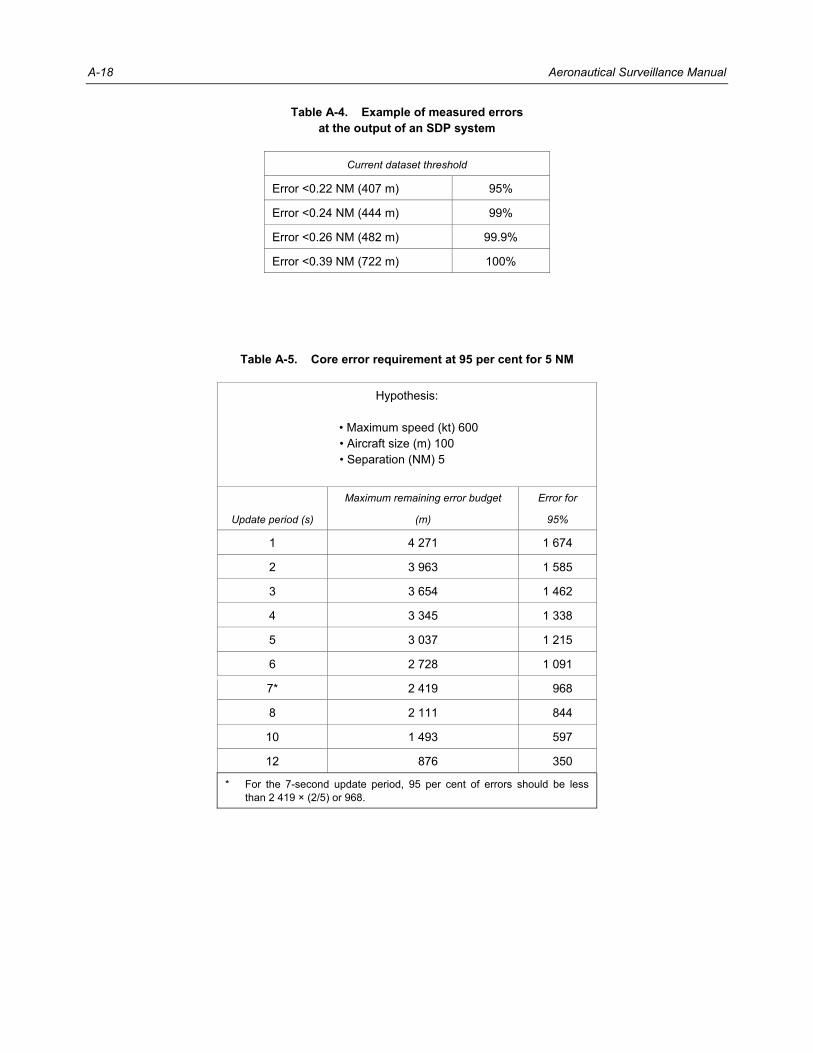
A-18 Aeronautical Surveillance Manual
Table A-4. Example of measured errors at the output of an SDP system
Current dataset threshold
Error <0.22 NM (407 m) 95%
Error <0.24 NM (444 m) 99%
Error <0.26 NM (482 m) 99.9%
Error <0.39 NM (722 m) 100%
Table A-5. Core error requirement at 95 per cent for 5 NM
Hypothesis:
• Maximum speed (kt) 600 • Aircraft size (m) 100 • Separation (NM) 5
Update period (s)
Maximum remaining error budget Error for
(m) 95%
1 4 271 1 674
2 3 963 1 585
3 3 654 1 462
4 3 345 1 338
5 3 037 1 215
6 2 728 1 091
7* 2 419 1 968
8 2 111 1 844
10 1 493 1 597
12 1 876 1 350
* For the 7-second update period, 95 per cent of errors should be less than 2 419 × (2/5) or 968.

Appendix A. Technical Performance Requirements A-19
Table A-6. Example of error budget for a single Mode S radar system
En-route scenario:
• 180 NM of coverage • 6-second update period • aircraft speed 600 kt.
Position error because of: Example
Nominal value (m)
Maximum value (m)
a) Data source measurement n/a — —
b) Data source to surveillance system delay
n/a — —
c) Remote subsystem processing n/a — —
d) Remote subsystem delay Transponder reply delay jitter +/– 0.08 µs
— included in sensor measurement error
e) RF link propagation delay 3 ms — 0.9
f) Sensor measurement/ processing error
Azimuth (1σ) = 0.068° Range (1 σ) = 15 m Azimuth (5 σ) = 1 978
440 m 1 978
g) Sensor processing delay 2 s (including ground communication delay)
— 617
h) Total error sensor output — — 2 596
i) Ground communication delay — — As per g)
j) SDP prediction error — — —
k) SDP delay — — —
l) Total error at beginning of update period
— — 2 596
m) Aircraft moving during update period
6 s — 1 852
n) Total position error not to exceed (1/2 separation – buffer = 4 580)
— 4 448 (less than the maximum permissible value)

A-20 Aeronautical Surveillance Manual
Table A-7. Example of error budget for multi-radar tracker system
Position error because of: Example
Nominal value (m)
Maximum value (m)
a) Data source measurement n/a — —
b) Data source to surveillance system delay
n/a — —
c) Remote subsystem processing n/a — —
d) Remote subsystem delay Transponder reply delay jitter +/– 0.08 µs
— included in sensor measurement error
e) RF link propagation delay 3 ms — 0.9
f) Sensor measurement/ processing error
Azimuth σ = 0.068° Range σ = 15 m (taken from the European Mode S specifications) Azimuth (5 σ)
395 m 15 m
1 978
g) Sensor processing delay 2 s (including communication delay)
— 617
h) Total error sensor output — — 2 596
i) Ground communication delay — — —
j) SDP prediction error 95% or error <407 m maximum = 722 m (see example in Table A-5)
— 722
k) SDP delay A few ms — 1
l) total error at beginning of update period
— — —
m) Aircraft moving during update period
Display update interval = 5 s — 1 543
n) Total position error Not to exceed (1/2 separation – buffer = 4 580)
— —
Note.— The errors coming from the sensor measurements and the transmission delays will combine in a complex manner in the multi-sensor tracker included in the sensor data processor. The result of this process is represented by the error in line j) which contains the result of the combination of all errors coming from the different sensors. Therefore, the total position error calculation restarts from line j).

Appendix A. Technical Performance Requirements A-21
Table A-8. Example of error budget for a stand-alone ADS-B system
Position error because of: Example
Nominal value (m)
Maximum value (m)
a) Data source measurement GPS error NIC = 5, Rc = 1 NM = 1 852 m
— 1 852
b) Data source to surveillance system delay
Time between GNSS receiver and transponder maximum 0.6 s
— 185.2
c) Remote subsystem processing
Error due to transponder extrapolation — —
d) Remote subsystem delay — — —
e) RF link propagation delay 3 ms — 0.9
f) Sensor measurement/ processing
— — —
g) Sensor processing delay — — —
h) Total error sensor output — — 2 038.1
i) Ground communication delay — — —
j) SDP prediction error — — —
k) SDP delay — — —
l) Ground communication delay — — —
m) Total error at beginning of update period
— — 2 038.1
n) Aircraft moving during update period
6 s — 1 852
o) Total position error Not to exceed (1/2 separation – buffer = 4 580)
— 3 890 (less than the maximum permissible value)
______________________

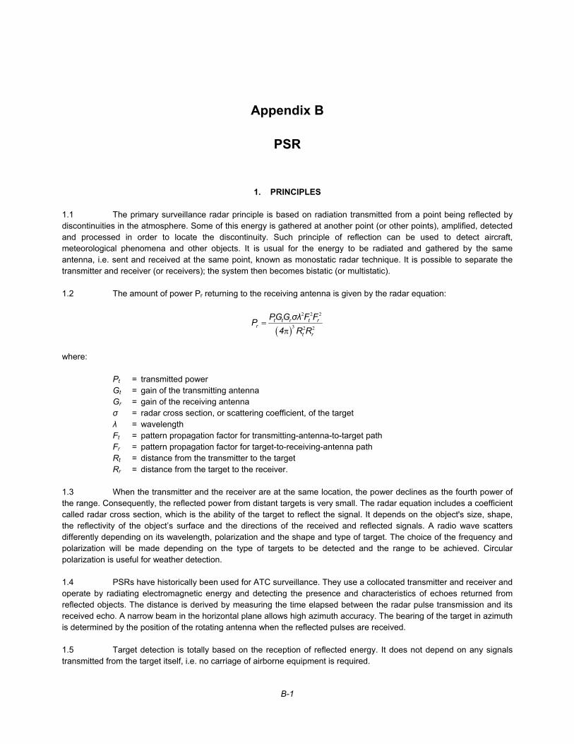
B-1
Appendix B
PSR
1. PRINCIPLES 1.1 The primary surveillance radar principle is based on radiation transmitted from a point being reflected by discontinuities in the atmosphere. Some of this energy is gathered at another point (or other points), amplified, detected and processed in order to locate the discontinuity. Such principle of reflection can be used to detect aircraft, meteorological phenomena and other objects. It is usual for the energy to be radiated and gathered by the same antenna, i.e. sent and received at the same point, known as monostatic radar technique. It is possible to separate the transmitter and receiver (or receivers); the system then becomes bistatic (or multistatic). 1.2 The amount of power Pr returning to the receiving antenna is given by the radar equation:
( )
2 2 2
3 2 2=
πt t r t r
rt r
PGG σλ F FP4 R R
where: Pt = transmitted power Gt = gain of the transmitting antenna Gr = gain of the receiving antenna σ = radar cross section, or scattering coefficient, of the target λ = wavelength Ft = pattern propagation factor for transmitting-antenna-to-target path Fr = pattern propagation factor for target-to-receiving-antenna path Rt = distance from the transmitter to the target Rr = distance from the target to the receiver. 1.3 When the transmitter and the receiver are at the same location, the power declines as the fourth power of the range. Consequently, the reflected power from distant targets is very small. The radar equation includes a coefficient called radar cross section, which is the ability of the target to reflect the signal. It depends on the object's size, shape, the reflectivity of the object’s surface and the directions of the received and reflected signals. A radio wave scatters differently depending on its wavelength, polarization and the shape and type of target. The choice of the frequency and polarization will be made depending on the type of targets to be detected and the range to be achieved. Circular polarization is useful for weather detection. 1.4 PSRs have historically been used for ATC surveillance. They use a collocated transmitter and receiver and operate by radiating electromagnetic energy and detecting the presence and characteristics of echoes returned from reflected objects. The distance is derived by measuring the time elapsed between the radar pulse transmission and its received echo. A narrow beam in the horizontal plane allows high azimuth accuracy. The bearing of the target in azimuth is determined by the position of the rotating antenna when the reflected pulses are received. 1.5 Target detection is totally based on the reception of reflected energy. It does not depend on any signals transmitted from the target itself, i.e. no carriage of airborne equipment is required.

B-2 Aeronautical Surveillance Manual
2. TYPES 2.1 PSR is used for medium range en-route surveillance, terminal area surveillance, approach monitoring and ground movement surveillance. The fundamental principles remain the same regardless of the application. 2.2 PSRs operate in the following frequency bands: “L” band, 1 215–1 350 MHz is usually used for en-route surveillance radars. The turning rate is 6–10 rpm
and the detection range is 120–200 N “S” band, 2.7–3.5 GHz, is usually used for airport approach and TMA surveillance. The turning rate is
12–15 rpm, and the instrumented detection range is 60–80 N Military, air defence and long-range warning radars use a turning rate of 6–10 rpm and may have an instrumented detection range of up to 200 N
“X” band, 8.0–10.5 GHz, is usually used for PAR and ground movement radar. “Ku” band, 15.5–15.7 GHz, is predominantly used for ground movement radars. “Ka” Band, 24–40 GHz, and “W” Band, 75–110 GHz, are used by short-range, high resolution ground
movement radars and automated systems for the detection of FOD on runways.
3. TECHNICAL ISSUES
3.1 Clutter 3.1.1 Electromagnetic energy is not only reflected by aircraft but also by any discontinuities in the atmosphere e.g. rain, snow or hail. Significant amounts of energy are also returned from the ground or nearby buildings, trees, road traffic, wind farms and, in the case of coastal radars, waves. Such echoes, which are reflected from objects other than the target of interest, are named clutter. Signal processing techniques are used with varying degrees of success to filter these unwanted returns (clutter). 3.1.2 In particular, deployment of wind turbines in the proximity of primary radars can have detrimental effects on their performance. The technical impact on ATC surveillance system performance has yet to be completely quantified; particularly the cumulative effect of large-scale wind turbine farms (i.e. where over 100 turbines are deployed) need further study. Wind turbines can result in: a) clutter; b) false targets caused by reflections from turbine blades; c) shadowing (targets behind the blades not being detected); and d) reduction of range in the direction of the wind turbine. With the height of a new wind turbine exceeding 200 m, the maximum radar cross section of the blade and supporting tower may be very large as shown in Figure B-1.

Appendix B. PSR B-3
Figure B-1. Radar cross section of a wind turbine compared to other reflecting objects
0,001 m–30 dBsm 2
0,01 m–20 dBsm 2
0,1 m–10 dBsm 2
1 m0 dBsm 2
10 m10 dBsm 2
100 m20 dBsm 2
1 000 m30 dBsm
210 000 m40 dBsm
2100 000 m
50 dBsm2
1 000 000 m60 dBsm
210 000 000 m
70 dBsm2
Stealthaircraft
UAVmissile
Fighteraircraft
Periscope
Cabincruiser
Cargoship
Largeaircraft
Windturbine
maximum

B-4 Aeronautical Surveillance Manual
3.1.3 Due to the broad Doppler return generated by rotating tips, the Doppler filtering systems are not always effective at removing the false plots generated by wind turbines. It is therefore recommended to carefully analyse any installations of wind turbines in close proximity of a PSR. More careful investigation on possible impact on ATC (e.g. approach path, route) should be undertaken when wind turbines are installed within the radar line of sight up to an obstruction height of 200 m or within a specified radius around PSR.
3.2 Use of composite material The trend today is to use composite material for small general aviation aircraft. This results in a smaller radar cross section which may result in degraded detection by a PSR.
4. CHARACTERISTICS OF L-BAND AND S-BAND PSR
4.1 Performance Typical overall performance of PSR radar is as follows: a) overall probability of target position detection: >90 per cent; b) average number of false target reports per antenna scan: <20; c) systematic errors: 1) slant range bias: <100 m; 2) azimuth bias: <0.1 degree; 3) slant range gain error: <1 m/NM; and 4) time-stamp error: <100 ms; d) random errors (standard deviation values): 1) slant range (m): <120 m; and 2) azimuth (degree): <0.15 degrees.
4.2 En-route and approach surveillance PSR has been used as the primary means of air traffic surveillance for decades. SSR and other cooperative means of surveillance have gradually replaced the PSR enabling the determination of horizontal and vertical positions and identity. Nevertheless, PSRs are still used for detection of: a) intrusion of non-cooperative targets; b) transponder failure; and

Appendix B. PSR B-5
c) significant weather.
4.3 SMR 4.3.1 SMR is the most widely used non-cooperative surveillance system for aerodrome surveillance. SMR is a primary radar that provides surveillance cover for the manoeuvring area, which is defined as that used for the take-off, landing and taxiing of aircraft. In A-SMGCS, the non-cooperative surveillance service is typically provided by one or several SMRs. 4.3.2 SMR systems are also known by the acronym “ASDE” which stands for “airport surface detection equipment”. Typical characteristics of SMR are: a) antenna dimension: 50–70 cm; b) rotation rate: 60 rpm; c) range: 4 km; and d) resolution: 5–20 m. 4.3.3 The aerodrome surveillance application requires high resolution in order to discriminate between closely spaced targets. It also needs accurate and timely position information at an appropriate update rate to determine target speed and direction. For a simple sensor system, the expected range for operational use under all specified weather conditions will not normally exceed 4 km. SMR provides surveillance of all aircraft and vehicles in this area with a high update rate (e.g. once per second). 4.3.4 An SMR is required to provide the best possible coverage of the airport surface. Usually it is required to give equivalent coverage to that achieved by visual observation from the control tower. However, in certain specific cases, the SMR may be required to augment the control tower view. In these circumstances, multiple SMR sensors may be required to achieve the required coverage. 4.3.5 Given the requirement to provide a “bird’s eye view”, the SMR antenna must be mounted as high as possible. As such, SMR coverage is defined by negative angle obstruction lines that govern visibility, for example, into aircraft parking areas and stands. Coverage prediction for SMR therefore involves a detailed analysis of local obstructions. Airport development can have a significant effect on SMR coverage and should therefore be kept under constant review. 4.3.6 Given the need to monitor airport surface traffic, elevation coverage is limited to about 100 m to minimize the coverage of airborne traffic. The coverage requirement of an SMR is therefore the inverse of that used in conventional surveillance radar. The fan beam directs the energy towards the ground while minimizing the power directed above the horizon.
5. MILLIMETRE RADAR
5.1 Aerodrome surveillance 5.1.1 Millimetre radar is an emerging technology used for aerodrome surveillance which provides higher resolution than traditional SMR. The use of very short wavelength results in poorer weather performance and limited

B-6 Aeronautical Surveillance Manual
range. However, the millimetre radar has the advantage of being smaller, lighter and typically having lower power requirements than the SMR. Millimetre radar is commonly used as a gap filler solution in areas of poor SMR coverage. Multiple antennas may be used in clusters, together with central processor, to extend the surveillance coverage. 5.1.2 Typical characteristics of the millimetre radar are: a) antenna dimension: 20 cm; b) rotation rate: 60 rpm; c) range: 1 km; and d) resolution: 0.25–5 m.
5.2 FOD detection 5.2.1 The key requirement for FOD detection is the ability to detect very small objects. In order to design a system capable of detecting such small objects, it is necessary to maximize the signal reflected by the target (i.e. the FOD) and to minimize any other signal that could obscure the target. These other signals could be generated by noise within the system itself, or energy reflected from the runway. 5.2.2 It is possible to design a radar which minimizes the reflections from the runway by reducing its detection cell, which can be considered as the individual spot size of the beam on the runway. If this cell is large, a lot of energy is reflected from the runway surface, which can then obscure a small signal from a piece of FOD. In general, the cell size is decreased by increasing the radar frequency and its bandwidth. By adopting a millimetre wave radar operating at over 90 GHz (over ten times higher than most SMRs) and with a bandwidth of 600 MHz, a system will have a detection cell of just 0.6 m2 at a distance of 1 km. By comparison, a standard SMR would have a cell size of around 30 m2. Objects which are invisible to an SMR can therefore be seen clearly by such radar. 5.2.3 Millimetre wave radars used for FOD detection are used in networks to provide complete runway coverage. FOD detection is performed through digital signal processing of consecutive radar scans. FOD identification is usually supported by optical or thermal cameras. 5.2.4 Typical characteristics of millimetre wave radar are: a) scan time: 30 s; b) range: 0.1–1 km; c) smallest detectable FOD size: 2 cm; d) FOD detection time: 60 – 180 s; and e) FOD location accuracy: better than 3 m.

Appendix B. PSR B-7
6. MSPSR
6.1 Principle 6.1.1 MSPSR refers to a sparse network of transmitters (Tx) and either a single receiver (Rx) or a network of receiver ground stations using static (i.e. non-rotating) antennas (see Figure B-2). These units receive signals reflected from the aircraft and prepare them for onward transmission to the centralized processing unit. The signal received defines an ellipsoid of constant bistatic range on which the target lies. The location of the transmitter and the receiver are the two loci of the ellipsoid. In the CPU an intersection point of a number of ellipsoids (at least three) is calculated, and this represents the 3-D position of the reflecting target. 6.1.2 These systems may use transmitters of opportunity like radio and television broadcast stations, mobile telephone base stations or dedicated transmitters specially deployed to avoid relying on third party illuminators. 6.1.3 The signal received via the reflected path is cross correlated with the direct signal from the transmitters in order to locate the position of the target reflecting the signals as shown in Figure B-3. 6.1.4 Although the principle is well established, the development of such systems for civil applications is still in its early stages, since it requires a lot of computation power.
Figure B-2. MSPSR general concept
Centralunit
ATCcentre
MSPSR
: Tx : Rx

B-8 Aeronautical Surveillance Manual
Figure B-3. Principle of the MSPSR
6.2 Passive MSPSR Passive MSPSR is also known as passive radar, passive coherent location radar or parasitic radar. Rather than having its own transmitter in the same way as conventional PSR, this system exploits opportunity transmissions (e.g. FM radio or digital TV transmitters). The perturbations caused by an aircraft disturbing the transmissions are processed by ground-based receiver stations, and a declaration of an aircraft’s presence can be made. The performance that can be obtained using FM radios is relatively low while the predicted performance that could be obtained using terrestrial digital video broadcast transmissions is somewhat better.
6.3 Active MSPSR 6.3.1 To be independent of opportunity transmissions, the active MSPSR uses a network of dedicated ground-based transmitters. Such systems are based upon bistatic techniques which were previously employed in a defence role. The system must use either CW or pulsed waveforms and coherent processing. Initial studies are very encouraging and give a positive indication regarding the feasibility of an active multistatic PSR system to support ATM applications. Assessments show that its potential performance complies with the requirements for approach/TMA even on low radar cross section targets (e.g. UAS). The coverage can be extended by adding Tx and Rx as necessary, in order to support various applications and also to enable operations over difficult terrain. 6.3.2 Multistatic radars offer several potential improvements when compared to conventional PSRs. In particular, they provide: a) 3-D detection in position and velocity; b) a higher renewal rate (e.g. 1.5 s instead of 4–5 s); and c) resistance to man-made noise and possibly to clutter created by the reflections from wind farms.
______________________
Reference signal(direct or data link)
Target signal

C-1
Appendix C
SSR PERFORMANCE CAPABILITIES
Note.— SSR provides EHS of aircraft compared to primary radar. Mode A/C provides, in addition to position reporting, rudimentary data link capabilities to report identity and pressure-altitude. Mode S provides more comprehensive data link capabilities, which are described in later sections.
1. SURVEILLANCE INFORMATION 1.1 Like primary radar, SSR can provide position (range and bearing) information in conjunction with identification. SSR is able to provide the information described in 1.2 and 1.3 below. 1.2 Information from Mode A/C. Mode A replies provide identity codes for aircraft ID purposes. The Mode A code contained in a reply is used to correlate the aircraft identity to the position report. The SPI pulse feature may be used in addition to Mode A codes to validate aircraft ID. Certain emergency conditions can be reported using special Mode A codes which are exclusively reserved for these purposes. Mode C replies provide pressure-altitude reporting, encoded with a 100-ft resolution. 1.3 Information from Mode S. In addition to the information described above, a Mode S ground station can obtain some or all of the following information from a Mode S transponder: a) the unique 24-bit address of the aircraft; b) aircraft “on-the-ground” status (used to aid processing of SSR replies in conflict alert systems and
radar data/FDPS); c) aircraft ID (in the form specified in item 7 of the ICAO flight plan); d) aircraft pressure-altitude with 25-ft resolution; and e) other information through use of the Mode S data link, including Mode S specific services. The ability to obtain the above information is dependent upon the level of the transponder fitted to the aircraft, except for the first two items which are available from all levels.
2. RELIABILITY AND INTEGRITY 2.1 Probability of detection. Because of the use of transponders, received signal levels have a 1/R2 relationship to range, instead of the 1/R4 relationship that exists in a primary radar. Therefore, an SSR system is able to achieve a high probability of detection (e.g. greater than 97 per cent) even at long range using relatively low power transmitters and simple receivers. Long-range performance is determined by interrogator/receiver and transponder characteristics and not by aircraft size or shape.

C-2 Aeronautical Surveillance Manual
2.2 False targets. Use of separate frequencies by SSR for interrogation and reply eliminates the false targets seen on primary radar systems because of ground clutter, weather returns and “angels.” Side-lobe replies are prevented by SLS circuitry in transponders. Further protection can be provided by RSLS in the ground system. Interrogations and replies received via reflecting surfaces can generate false targets with Mode A/C SSR systems. A number of techniques can be used to minimize this problem. In a full SSR Mode S environment there should be no persistent false targets because the selective interrogation will only be transmitted when the aircraft is within the direct antenna beam. 2.3 Data protection. Protection against corruption of reply code information for Mode A/C SSR depends on frequent repetition of the reply code information as a means of validation. This process can be enhanced with tracking, confidence determination and other similar processes. Protection against corruption of the data contained in Mode S interrogations and replies is provided by CRC procedures, which are designed to achieve error rates of less than one undetected error in 107 112-bit messages. Where tracking and confidence determining processes are employed in the ground system, they may be used to assess the validity of the barometric altitude data. 2.4 Resolution. Surveillance resolution is a measure of the ability of the radar to separate replies from two or more aircraft that are in close proximity. Resolution has an influence on the ATC separation standards to be applied within the coverage volume of the radar. 2.5 Azimuth resolution. The azimuth resolution of Mode A/C SSR ground stations that use “sliding window” signal processing is generally slightly in excess of the antenna azimuth beamwidth. On the other hand, the azimuth resolution of Mode A/C SSR ground stations that use monopulse signal processing can be improved to a fraction of the antenna azimuth beamwidth. A Mode S ground station should experience no resolution problem for any aircraft pair where at least one carries a Mode S transponder. 2.6 Range resolution. Mode A/C reply pulse trains from aircraft at close azimuths may overlap in time if the aircraft are close in range. If the SSR signal processing is unable to resolve the framing pulses, a loss of detection can result. Synchronous garbling can occur if code information pulses from one reply overlap pulse positions from another reply on successive interrogations. Monopulse processing of Mode A/C reply pulse trains offers some improvement over sliding-window processing, as overlapped pulse trains can be separated in most cases on the basis of monopulse OBA estimates. Mode S is not susceptible to detection losses or code garbling from aircraft close in range because only one Mode S transponder replies to a given selective interrogation. 2.7 Accurate position reports. SSR ground stations should be able to provide accurate position reports on targets that are correctly detected. The required accuracy is dependent upon the desired separation minima (elements on the establishment of separation minima can be found in the PANS-ATM, Chapter 8). The conventional sliding-window technique for SSR is able to support current radar separation minima of 18.5 km (10 NM), 9.3 km (5 NM) and 5.6 km (3 NM), depending on the range of the aircraft from the radar. Monopulse and Mode S ground stations are significantly more accurate and therefore may support closer separation at longer range.
3. UTILIZATION OF SSR INFORMATION 3.1 Analog display of SSR reply pulses. In early systems, analog video pulse trains of Mode A/C replies were displayed on a PPI, either alone or superimposed on primary radar returns. Currently SSR plot extractors (SSR digitizers) process all the replies from an aircraft during each scan of the antenna to form a digital target report (“plot”) which can contain aircraft position, identification code and flight level (Mode S systems may also provide a range of additional information). SSR plot information may be further processed before display in RDPS, which may perform mono-radar or multi-radar tracking, conflict alert processing, MSAW processing, etc. SSR plot information is normally displayed as a plot position symbol which may have an adjacent alphanumeric label providing the SSR identification information and pressure-altitude information. Further, Mode S information, such as aircraft intent data, may also be displayed as part of the alphanumeric label or as selectable data blocks.

Appendix C. SSR Performance Capabilities C-3
3.2 Volume of coverage. SSR should provide coverage under all-weather conditions at all bearings and at all ranges between at least 1.85 km (1 NM) and the maximum operationally required range (typically 370 km (200 NM) for long-range systems and 150 km (80 NM) for short-range systems), and at all operational altitudes up to at least 30 480 m (100 000 ft) above mean sea level between at least the angles of elevation of 0.5 and 40 degrees (or 0.5 degrees above the terrain in directions of terrain masking). Coverage at ground level on airfields may be required for some SSR Mode S data link applications. 3.3 Interference. SSR systems should perform their operational function without degrading the performance of other radio, radar or electronic equipment on board aircraft or on the ground and without being affected by such other equipment. 3.4 Aircraft manoeuvres. The probability of detection of manoeuvring aircraft can be reduced due to transponder antenna shielding, which can be alleviated by careful site selection or multi-radar processing, as well as by transponder antenna diversity systems.
4. TECHNICAL PERFORMANCE CRITERIA 4.1 Detection probability. The PD is measured inside the volume of coverage. It should be at least 95 per cent everywhere within the volume of coverage. The PD is influenced by siting, uplink and downlink power budgets and other factors. 4.2 False detection. False targets are mainly caused by main beam reflections; detection through side lobes which can give rise to ring-around at shorter ranges; and second-time-around replies from aircraft beyond the maximum range that appear to be detected at shorter range. Within any scan, the false target count should be less than 2 per cent of the total target count. False detection can be reduced by good vertical antenna cutoff, judicious siting, STC and scan-to-scan processing. 4.3 Garbling. Overlapping replies can give rise to missed detection, inaccurate detection and Mode A and Mode C code corruption, particularly when targets are near each other and thus subject to synchronous garbling. 4.4 Position detection accuracy. To a first approximation, the detection accuracy can be characterized by the bias and standard deviation in range and azimuth throughout the volume of coverage. Typical figures of standard deviation are 250 m and 0.15 degrees for conventional SSR, and 100 m and 0.06 degrees for monopulse and Mode S ground stations. The data quantization should be consistent with the accuracy. Biases in range and azimuth should be minimized and monitored very carefully, particularly if data from several overlapping radar sites are merged. In particular, the radar north should then be aligned with geographical north to within about 0.1 degree (an azimuth bias of 0.3 degrees at 370-km range corresponds to an error of 2 km). In the case of a single radar site, these biases are less important, since the distance between two proximate aircraft will remain correct. 4.5 Mode A and Mode C. Reports with missing or invalid Mode A codes should occur with less than 2 per cent probability in any scan. Reports with missing or invalid Mode C codes should occur with less than 4 per cent probability in any scan for Mode C-equipped targets. Reports with undetected corrupted Mode A codes should occur with less than 0.1 per cent probability in any scan. Reports with undetected corrupted Mode C codes should occur with less than 0.1 per cent probability in any scan. 4.6 Mode S. The Mode S message undetected error rate should be less than one undetected error in 107 112-bit messages. This message protection is provided by the CRC provisions included in the Mode S coding. 4.7 Ground station capacity. (Maximum number of aircraft per scan) should be specified according to local traffic forecast. For example, interrogators operating in high traffic areas may need a capacity of 900 aircraft.

C-4 Aeronautical Surveillance Manual
4.8 Processing and display criteria. Processing and display equipment should be able to handle the specified ground station capacity. They should not introduce excessive delay (e.g. less than half the scan period) between detection and display. 4.9 Test and evaluation methods. Technical performance of the SSR can be tested and evaluated by measurements within the ground station itself, and by comparing the ground station output with a reference based on test flights, employing either an independent means of trajectory determination or trajectory reconstitution, based on non-real-time tracking of recorded radar data. Details are given in the Manual on Testing of Radio Navigation Aids (Doc 8071), Volume III — Testing of Surveillance Radar Systems.
______________________

D-1
Appendix D
SSR SYSTEM TECHNIQUES
1. SYSTEM POWER CONSIDERATIONS
1.1 The balance between uplink and downlink power budgets 1.1.1 SSR systems for civil aviation applications are normally designed so that the downlink is more sensitive than the uplink, typically by 3 to 6 dB. This ensures that whenever a transponder is triggered by a ground interrogator, there is a very high probability that the resultant reply will be received properly by the associated ground receiver. The maximum uplink range is that range for which the transponder’s received power level is at the MTL of the transponder. MTL is defined as the signal level at which a transponder responds to an interrogation signal or a ground station receiver responds to a reply signal with a 90 per cent reply ratio. The transponder MTL is measured at the antenna end of the transmission line. To a first order approximation, the “round trip” reply-to-interrogation ratio at the output of the ground receiver is then assumed to also be 90 per cent (rather than the 81 per cent which it would be if both up and downlinks were each balanced at 90 per cent probability). It should also be noted that this is the probability of a single successful “round trip” interrogation and reply. The actual “probability of detection” at the output of defruiting and plot extraction processing is dependent on sufficient successful single round trip replies from a sequence of interrogations for the processing technique employed. 1.1.2 The SSR system can become saturated and will degrade in performance if transponders are over-interrogated and/or over-suppressed. 1.1.3 Aircraft transponders can receive from and reply to only one ground station at a time, so it is important that they not be “occupied” by having to respond to more stations than absolutely necessary. 1.1.4 An excessive power margin can enable triggering of the transponder by side-lobe interrogations or by false P1-P2 pairs. Unwanted suppressions can then occur which will reduce the availability to reply to other ground stations. 1.1.5 The radar equation applied to SSR is the following:
Prec = Ptrd GA GT 1 λ2
Lat LI LT (4π)2 R2
where: Prec is the received power at the input of the receiver (watts); Ptrd is the transmitted power at the output of the transmitter (watts); GA is the ground station antenna gain with respect to the isotropic in the direction of the transponder; GT is the transponder antenna gain with respect to the isotropic;

D-2 Aeronautical Surveillance Manual
LI is the sum of the losses between the interrogator and the antenna; LT is the sum of the cable losses between the antenna and the transponder; Lat is the atmospheric attenuation; λ is the wavelength (metres); R is the range between the ground station and the transponder antennas (metres). Note.— The values for GA and GT to be used in this equation need to be chosen carefully. GA, the gain of the ground station antenna, will vary as a function of azimuth and elevation. For reliable operation over the required coverage volume, the gain should not fall below the chosen value over all elevations in this volume at any given range. Furthermore, the gain should not fall below the chosen value over the azimuth beamwidth for which replies are required. These considerations lead to an effective gain value which will be less than the peak gain of the ground station antenna. GT, the gain of the transponder antenna, can be expected to be more constant in normal situations, but it will vary with elevation, and its effective value will be determined by the aircraft attitude. 1.1.6 The number of replies in a beam dwell is proportional to the beam dwell time and the PRF. The beam dwell time is defined as the beam-width (in degrees) divided by the antenna scanning rate (in degrees/second).
Number of replies = beamwidth (degrees) PRF (s–1)
antenna scanning rate (degrees/s)
1.2 The uplink power budget 1.2.1 The elements of the uplink are shown as a block diagram in Figure D-1. Analysis of the uplink is facilitated if the elements common to the ground station (transmitter power, interrogator feeder loss and interrogator antenna gain) are combined to give a term for the ERP:
ERP(I) = Ptrd GA/LI where ERP(I) and Ptrd are in watts and GA and LI are ratios. 1.2.2 The power level received at the antenna of the transponder is given by:
Pant(T) = ERP(I) 1
1
λ2
Lat R2 (4π)2
where Pant(T) and ERP(I) are in watts, Lat is a ratio and λ and R are in metres. 1.2.3 If λ = 29.13 cm (f = 1 030 MHz), then the atmospheric loss (which varies with wavelength) can be shown to be 0.0065 dB per nautical mile (1.85 km). If R is in nautical miles, the above equation can be written in a logarithmic form:
Pant(T) = ERP(I) – 0.0065 R – 20 log(R) – 98.05 where Pant(T) and ERP(I) are in dB above 1 milliwatt (dBm).

Appendix D. SSR System Techniques D-3
Figure D-1. Uplink margin. ERP equals 79.4 dBm
Transponder receiver
Worst case MTL = –99 dBW (–69 dBm)
(Annex 10, Volume IV, 3.1.1.7.5.1)
Prec
Cable loss: –3 dB
Antenna gain: 0 dB
P (T)ant Minimum level (without margin): ( 66 dBm)
–96 dBW–
Minimum level (without margin): 49.4 dBW (79.4 dBm)
1/ 2 loss: 144.1 dBR
Atmospheric attenuation:1.3 dB
P (l)rad
Sensor antenna gain:G dBA
Feeder losses: L dBl
Interrogator transmitterpeak power: Ptrd
Free space loss = 145.4 dBλ = 29.13 cm
R = 200 NM
16/2/12 Corr. No. 1

D-4 Aeronautical Surveillance Manual
1.2.4 Figure D-2 plots ERP(I), the power required to be radiated by the antenna of the ground station, to provide given power Pant(T) at the transponder antenna at range R, for values of R between 18.5 and 555 km (10 and 300 NM). The actual power into the receiver of the transponder is calculated by taking into account the transponder’s antenna gain and cabling loss:
Prec = Pant(T) GT/LT where Prec and Pant(T) are in watts and GT and LT are ratios (linear form).
Prec = Pant(T) + GT – LT where Prec and Pant(T) are in dBm and GT and LT are in dB (logarithmic form). 1.2.5 Figure D-1 shows atmospheric loss figures for a 370 km (200 NM) range and transponder parameters corresponding to those defined in the standards for worst case limits of transponder performance. The uplink margin is given by the amount the radiated power level exceeds the minimum necessary to trigger the transponder. The uplink margin obtained is determined by transmitter power, antenna gain and feeder loss of the ground station. It should be noted that the last two factors also affect downlink margins.
Figure D-2. Relationship between power and range at 1 030 MHz
P (T) =ant
– 56 dBm
– 59 dBm
– 62 dBm
– 65 dBm
– 68 dBm
– 71 dBm
– 74 dBm
– 77 dBm
– 81 dBm
50
93 185
100
280
150 200
370
250
463
300
55540
50
60
70
80
90
P (T) = Power level at transponder antennaant
(km)
(NM)Range
ER
P (d
Bm
)

Appendix D. SSR System Techniques D-5
1.2.6 Mode S data link delivery to aircraft on the airport surface may result in excessive signal dynamic range at the transponder receiver caused by very short minimum ranges. Because of this very large dynamic range, consideration should be given to the use of an auxiliary system with transmitter power programming to match the transmitter power to transponder range. 1.2.7 Allowance must be made for the aircraft transponder to receive interrogations above MTL across a sufficient portion of the ground station antenna beamwidth (nominally 3-dB beamwidth) to enable a sufficient number of replies to be received for subsequent processing (e.g. plot extraction). Depending on the interrogation rate, antenna turning rate, antenna azimuthal pattern and antenna elevation pattern, this number of replies will require operation to a certain level below the peak gain level of the antenna. This level is typically between 2 and 4 dB down on the peak. Note that the signal levels shown are based on free space propagation. Lobing effects can cause significant variations to these levels.
1.3 The downlink power budget 1.3.1 The elements of the downlink are shown as a block diagram in Figure D-3. Analysis of the downlink is facilitated if the elements common to the transponder (transmitter power, transponder feeder loss and transponder antenna gain) are combined to give a term for the ERP:
ERP(T) = Ptrd GT/LT where ERP(T) and Ptrd are in watts and GT and LT are ratios, or in a logarithmic form:
ERP(T) = Ptrd + GT – LT where ERP(T) and Ptrd are in dBm and GT and LT are in dB. 1.3.2 The power level received at the antenna of the ground station is:
Pant(I) = ERP(T) 1
1
λ2
Lat R2 (4π)2
where Pant(I) and ERP(T) are in watts, Lat is a ratio and λ and R are in metres. 1.3.3 If λ = 27.52 cm (f = 1 090 MHz), then the atmospheric loss (which varies with wavelength) can be shown to be 0.0090 dB per nautical mile (1.85 km). If R is in nautical miles, the above equation can be written in a logarithmic form:
Pant(I) = ERP(T) – 0.0090 R – 20 log(R) – 98.54 where Pant(I) and ERP(T) are in dB above 1 milliwatt (dBm). 1.3.4 Figure D-4 plots ERP(T), the ERP from the antenna of the transponder and the resultant power at the antenna of the ground station Pant(I), as a function of range R, for values of R between 18.5 to 555 km (10 and 300 NM). The actual power into the receiver of the ground station is calculated by taking into account ground station antenna gain:
Prec = Pant(I) GA/LI where Prec and Pant(I) are in watts and GA and LI are ratios.

D-6 Aeronautical Surveillance Manual
Figure D-3. Downlink margin. Receiver minimum sensitivity power at receiver input
Transponder transmitterworst case power output
Ptrd = 24dBW (54 dBm)
Cable loss: –3 dB
Antenna gain: 0 dB
P (T)rad 21 dBw (51 dBm)
1/ 2 loss: 144.1 dBR
Atmospheric attenuation:1.8 dB
P (l)ant
Prec
Sensor antenna gain:G dBA
Feeder losses: L dBl
L dBl
Interrogator receiverminimum sensitivity: –115 dBW
–85 dBm
Free space loss = 145.9 dBλ = 27.52 cm
R = 200 NM
21 dBW (Annex 10, IV, 3.1.1.7.11.1)
–124.9 dBW(– 94.9 dBm)
Minimum gain(without margin)
9.9 dB
16/2/12 Corr. No. 1

Appendix D. SSR System Techniques D-7
Figure D-4. Relationship between power and range at 1 090 MHz
1.3.5 Figure D-3 gives atmospheric loss figures for a 370 km (200 NM) range, and transponder power output at the lowest level allowed in the Standards, 24 dBW (250 W). The downlink margin is the amount by which the received power level exceeds the receiver sensitivity level. SSR interrogator/receiver sensitivity has traditionally been defined as the “tangential” sensitivity (see 2.4.2.1 below for receiver sensitivity). In many applications a more realistic figure to use may be the minimum SNR required for reliable operation of subsequent signal processors (plot extractors). This is particularly true for monopulse systems using sum/difference ratio techniques where there must be an adequate SNP in the difference channel for maximum range replies.
1.4 The relationship between absolute power levels and power density levels
1.4.1 In some instances it is convenient to work with power density levels in watts per square metre at various ranges for uplink and downlink signal paths. The received power levels can then be calculated from knowledge of the effective area of the receiving antenna. The relationships for these calculations are summarized below:
P (I) =ant
– 90 dBm
– 93 dBm
– 96 dBm
– 99 dBm
– 102 dBm
– 105 dBm
– 108 dBm
– 111 dBm
– 114 dBm
5093 185
100280
150 200370
250463
300555
10
20
30
40
50
60
P (I) = Power level at interrogator antennaant
(km)
(NM)Range
ER
P (d
Bm
)

D-8 Aeronautical Surveillance Manual
a) for an isotropic antenna transmitting power PT, the power density at range R metres is PD = PT/(4πR2) W/m2;
b) if the gain GT of a transmitting antenna in a given direction is defined as the ratio of the power radiated
in that direction to the power radiated in the same direction by a standard (isotropic) antenna, then the power density in that direction is:
PD = GT PT/(4πR2) W/m2
Note.— GT is a dimensionless ratio in the linear form, not a number of dB. c) using this equation, the power density at any range can be calculated for a given transmitting system; d) a receiving antenna with a gain GR has an effective receiving area AR given by:
AR = GR (λ2/4π) m2 where λ is in metres e) the power delivered by a matched antenna to its load is then:
Prec = PD AR W f) substituting from previous equations generates the radar equation for transponder systems:
Prec = PT GT GR λ 2/(4πR)2
2. GROUND STATION INSTALLATION
2.1 Siting
2.1.1 Number of ground stations In planning the siting of ground stations, care should be taken to ensure that the number of ground stations with overlapping coverage is kept to a minimum consistent with the operational requirement.
2.1.2 Effects of obstacles 2.1.2.1 Natural and artificial obstacles around an SSR site can have detrimental effects due in particular to reflection or diffraction phenomena. It should be emphasized that reflections of the main lobe can cause serious problems such as false targets. 2.1.2.2 Diffraction phenomena can occur when portions of the beam are obstructed by buildings or other surfaces. Differences between the direct path and the path diffracted by an obstacle perturb the azimuth measurement. Reflection from a non-horizontal ground can cause the image to be displaced in azimuth. Combining of the direct and reflected signals produces a distorted beam shape. It is therefore advisable to avoid large vertical reflecting surfaces within a reasonable distance of the SSR ground station antenna. This distance will depend on the effective cross section of the reflecting surface and its elevation with respect to the ground station.

Appendix D. SSR System Techniques D-9
2.2 Interrogator antenna
2.2.1 HRP 2.2.1.1 Interrogation pulses are radiated by a directional antenna. For a mechanically rotated antenna, the beamwidth in azimuth should be sufficiently narrow, typically between 2 and 3 degrees at the 3 dB points, but it should be noted that there are a minimum number of replies necessary for reliable processing and display. This minimum will depend on the particular processing and display facilities provided. A typical requirement for “sliding window” SSR plot digitizers is four to eight replies per beamwidth on each interrogation mode. MSSR plot digitizers typically require two to four replies per beamwidth on each mode. It should also be noted that there is a direct relationship between the desired number of replies per beamwidth, the rate of interrogation, the antenna beamwidth and the rate of rotation of the antenna (see 1.1.6 of this appendix). 2.2.1.2 The horizontal beamwidth of the antenna is often made as narrow as possible in order to improve azimuth accuracy. For a mechanically rotated antenna, a narrow horizontal beamwidth reduces beam dwell time and therefore reduces the Mode S capacity of the ground station. A good compromise has been found to be a monopulse antenna with a beamwidth in the order of 2.4 degrees. 2.2.1.3 Azimuth pattern side lobes should be as low as practicable. A level at least 24 dB down from the main lobe is desirable.
2.2.2 VRP 2.2.2.1 Interrogation pulses should be radiated on an antenna which provides adequate signal strength between the angles of 0.5 and 40 degrees, to the operationally required range and altitude. 2.2.2.2 Another important characteristic is the ability to lessen the energy directed at the ground. Reflected energy from the earth can have a significant effect on the radiation pattern in space of an SSR antenna. For targets at certain elevation angles, the direct and reflected energy combines in phase, giving a large increase in signal strength, while at certain other angles the signals combine out of phase, causing significant reductions in signal strength. This can have a number of undesirable effects, including: a) loss of replies from aircraft in regions of reduced signal strength; b) interrogation of aircraft beyond ranges of operational interest in regions of increased signal strength,
possibly interfering with the operation of other ground station receiver systems; and c) degradation of azimuth accuracy when the magnitude of the reflection is not uniform across the
antenna beam. This causes less variation in signal strength on one side of the beam than on the other, shifting the effective centre of the beam.
2.2.3 Techniques for achieving reduced low angle radiation Inherent limitations of small vertical aperture antennas (e.g. “hog-trough antennas”) can be overcome by designing LVA antennas (five wavelengths or more). Antennas of this type are typically implemented from superposed columns of dipoles driven by signals of appropriate phase and amplitude. LVA antennas are typically used for MSSR and Mode S.

D-10 Aeronautical Surveillance Manual
2.2.4 Influence of antenna height above ground on VRP 2.2.4.1 At most sites the VRP will be affected to some degree by reflected energy from the ground. The magnitudes of the peaks and nulls will be dependent on the reflection characteristics of the reflecting ground, and the number of peaks and nulls will depend on the height above the reflecting ground surface of the antenna. 2.2.4.2 The peaks and nulls will occur at intervals of approximately nλ/4h radians, where λ is the wavelength, “h” is the effective antenna height, and “n” is odd for peaks and even for nulls. Figure D-5 illustrates the geometry of reflection, the resultant lobing structure, and the variations in signal strength as a function of range seen by a constant-altitude aircraft. This approximation for calculating peaks and nulls is only valid if the reflecting ground is substantially level out to a range of approximately 2.8 to 5.6 km (1.5 to 3 NM), dependent on antenna height. 2.2.4.3 Sloping ground can tilt the lobing pattern up or down. Careful attention should be paid to site selection and antenna tower height to achieve the best operational performance. Raising the antenna height tends to increase the number of nulls, but reduces the depth of each individual null. This is shown in Figure D-6 which presents the lobing patterns for a given antenna at effective heights of 8.5 and 25 m.
2.2.5 SLS antenna 2.2.5.1 The main requirement is that the control pattern covers the directional pattern side lobes and back lobe. Another essential characteristic for proper functioning is that the patterns of the control and directional antennas match in the vertical plane, so that the P1/P2 power ratio can be maintained over all elevation angles. If separate transmitters are used for P1 and P2 (or P6 and P5 for Mode S), care must be taken to ensure that the P1/P2 (P6/P5 for Mode S) power ratio in space is maintained at the levels required for SLS (Annex 10, Volume IV, Chapter 3, 3.1.1.7.4.1 and 3.1.2.1.5.2.5). 2.2.5.2 The best solution to meet these requirements is that SLS and directional antennas be designed in a common assembly. Generally, the SLS pattern is produced by feeding the central part of the directional antenna with suitable amplitude and phase. Back lobes can be covered by a special radiator. 2.2.5.3 Another solution uses a separate omnidirectional antenna to radiate the SLS pattern. Because of physical constraints, the phase centre of a separate antenna will often be offset from the phase centre of the directional antenna. This causes the ratio between P1 and P2 to change with the target azimuth and elevation angle. An off-mounted solution should be reserved to upgrade older equipment and should be avoided in new installations.
2.2.6 Monopulse antenna patterns MSSR systems require antennas that provide information about the OBA of received signals usually as “sum” and “difference” outputs. A comprehensive description of monopulse signal processing is given in Appendix E. As monopulse processing uses the relative amplitudes or phases of sum and difference outputs to determine off-boresight azimuth, it is important that these relative values are maintained within appropriate tolerances as a function of off-boresight angle over the elevation angle coverage of the antenna. The use of the monopulse technique is a prerequisite for a Mode S scanning beam interrogator.
2.2.7 Feeder system The ground station feeder system connects the antenna to the transmitters and receivers and includes rotating joint channels, coaxial cables and RF change-over units. The characteristics of the feeder system are an important part of the total system, especially with monopulse systems, where the phase and amplitude matching of each channel of the feeder system must be maintained within appropriate tolerances for the type of processing being used.

Appendix D. SSR System Techniques D-11
Figure D-5. Effects of surface reflection
Real antennaDirect ray
Et
EtEt
Δ = 2h r sin EtImage
antenna
hr
hr
Reflected ray
To target
(a) Geometry of reflections
(b) Lobing structure
(c) Signal of surface reflections.
Free spacepattern
Horizon
E = tλ2hr
SN
Range
Note.— = Angle of incidence = Height of antenna above reflecting surface = Wavelength = Signal-to-noise ratio
Eh
S/N
t
r
λ
16/2/12 Corr. No. 1

D-12 Aeronautical Surveillance Manual
Figure D-6. Typical antenna lobe structure envelope representing
90 per cent probability of detection
50
50
100
100
150
150
200
200
250
250
10
10
20
20
30
30
40
40
50
50
60
60
30°
30°
10°
10°
5°
5°
3°
3°
1°
1°
Altitude(thousands
of feet)
Altitude(thousands
of feet)
Elevation(degrees)
Elevation(degrees)
Slant range(NM)
Slant range(NM)
A. 8.5-m antenna height
B. 25-m antenna height

Appendix D. SSR System Techniques D-13
2.3 Ground station transmitter
2.3.1 Transmitter power 2.3.1.1 The transmitter power output necessary to achieve a given operational performance objective is highly dependent on the gain and radiation pattern of the antenna with which it is being used. The uplink power budget has been discussed in 1.2.1 of this appendix. 2.3.1.2 If the control pattern for ISLS is not provided by an antenna integrated with the directional antenna, then a different power level may be required to adequately drive the control pattern antenna. Separate antennas of this type should be avoided for new installations. 2.3.1.3 Where the full coverage of the system is not required, the interrogator power should be reduced as recommended in Annex 10, Volume IV, Chapter 3, 3.1.1.8.2. It should be noted that digital techniques allow the reduction of transmitted power in predefined azimuth sectors in order to avoid unwanted replies due to reflections, for example.
2.3.2 Techniques for rejecting ISLS Mode A/C transponders are suppressed on receipt of P1-P2 pulse pairs (see Annex 10, Volume IV, Chapter 3, 3.1.1.7.4) as shown in Figure D-7. Mode S transponders are prevented from replying on receipt of P5 pulses which mask the sync phase reversal of P6 (Annex 10, Volume IV, Chapter 3, 3.1.2.10.3.1). P2 or P5 pulses are radiated by the interrogator via a “control” pattern which should cover all side lobes of the directional pattern over the operational angles of elevation. This will likely require that the antennas for the directional and control patterns be designed in a common assembly so that the same effective height above the ground can be maintained for both, and a constant phase relationship maintained as the directional antenna rotates.
Figure D-7. Pulse amplitude discrimination in transponder for SLS facility
Transponder suppresses
Transponder maysuppress or reply
Transponder repliesP1 P2 P3
Controlpulse
0 dB
9 dB

D-14 Aeronautical Surveillance Manual
2.4 Ground station receiver
2.4.1 Receiver bandwidth and phase characteristics 2.4.1.1 The bandwidth of the receiver should be adequate to reproduce faithfully the pulses transmitted by the transponder (pulse rise time 0.1 microsecond) and to accommodate the drift in transponder transmitter frequency. Specifically, the minimum overall receiver bandwidth, which is typically determined by the IF filter, should be at least plus or minus 4 MHz at the 3 dB points. 2.4.1.2 The phase characteristic of the receiver should be linear within plus or minus 10 degrees over a frequency range of plus or minus 4 MHz to provide faithful detection of Mode A/C reply pulses. However, based on observations of actual Mode A/C transponder reply frequency distributions, prudent filter amplitude and phase bandwidth design should allow for reply carrier frequencies ranging from approximately 1 085 MHz to 1 095 MHz. More stringent receiver amplitude and phase specifications may be required to support the monopulse processing requirements of the ground station (see 2.3 of Appendix E).
2.4.2 Receiver sensitivity 2.4.2.1 Receiver sensitivity has traditionally been defined for the SSR ground station receiver in terms of the tangential sensitivity as determined manually with an oscilloscope. The tangential sensitivity is equal to the amplitude of a pulsed input to the receiver that raises the observed noise amplitude by its own width (i.e. aligns the negative peaks of the noise on the pulse with the positive peaks of the noise alone). This measurement can be made with a linear or non-linear (e.g. logarithmic) receiver transfer function for a square-law detector as illustrated in Figure D-8. Measured by this method, the receiver should be more sensitive than 85 dBm as indicated in Figure D-3. This sensitivity, when associated with a suitable antenna and feeder system, is adequate to provide a downlink range of 370 km (200 NM) for transponders having minimum specification output power. Note.— Caution should be exercised in respect of measuring and using this sensitivity value. The definition is framed in terms of a single pulse response. Where the receiver drives a digital plot extractor, it is also necessary to consider the plot extractor requirements in terms of the signal-to-noise ratio for reliable defruiting, plot extraction and code validation from a sequence of reply pulse trains. 2.4.2.2 There are several alternative techniques available for determining the receiver sensitivity. Among these alternatives are: a) measurement of the receiver mean-square noise power level; b) measurement of the receiver noise figure; and c) measurement of the overlap of the probability distributions of noise only and signal plus noise. Note.— Equipment which passes the simple oscilloscope test may fail accurate quantitative measurements. In current and old equipment, allowances may be made for this if desired, but new equipment should meet the more stringent specification. 2.4.2.3 The mean-square noise power can be determined directly by calibrating the receiver gain, sampling the receiver output in the absence of a reply signal to obtain multiple independent measurements of the instantaneous receiver noise power, and processing the resulting samples statistically to obtain the mean-square value of the Gaussian receiver noise. The tangential sensitivity measured, as illustrated in Figure D-8, is approximately 9 dB greater than the mean-square receiver noise power, i.e. a tangential sensitivity of –85 dBm corresponds to a mean-square noise power level of –94 dBm.

Appendix D. SSR System Techniques D-15
Figure D-8. Pulse signal on an A-scope with square-law second detector
2.4.2.4 The receiver noise figure may be measured directly with any of several commercially available noise figure measurement instruments that employ calibrated noise sources. The noise figure in dB is approximately equal to 114 – B + N, where “B” is the 3 dB receiver bandwidth in dB relative to 1 MHz, and “N” is the mean-square noise power in dBm. That is, a mean-square noise of –93 dBm and an effective bandwidth of 10 MHz (10 dB relative to 1 MHz) correspond to a receiver noise figure of 11 dB. Note.— Noise bandwidth is dependent on filter characteristics and can vary significantly from 3 dB bandwidth. 2.4.2.5 If the probability distributions of noise-only and signal-plus-noise are plotted on the same axes for the case where the SNR is 8 dB, i.e. tangential sensitivity, the area of the noise only distribution that lies above the point at which the two distributions cross over, and the area of the signal-plus-noise distribution that lies below the point at which the two distributions cross over, will be constant and independent of receiver law. These areas, expressed as a percentage of the total distribution area, are 6.6 per cent and 8.1 per cent, respectively, and can easily be measured using sampling techniques for automatic monitoring.
Random peaks
Time

D-16 Aeronautical Surveillance Manual
2.4.2.6 It is desirable to have a method of reducing the receiver sensitivity to a preset level at the time of transmission of the interrogator pulses and to increase the sensitivity to a normal level at a preset rate. 2.4.2.7 At 15.36 microseconds (corresponding to 1.85 km (1 NM) plus transponder delay) after pulse P3, the gain should normally be reducible to a value between 10 and 50 dB below maximum sensitivity. The recovery rate should be adjusted to suit local conditions. A rate of 6 dB for each doubling of range is satisfactory for most applications. 2.4.2.8 Control of receiver sensitivity in this way has two benefits: a) it normalizes the amplitude of received signals to make them vary less with range, which reduces the
required dynamic range of the receiver, thus reducing susceptibility to pulse stretching and distortion; and
b) it discriminates against unsynchronized replies, arriving from aircraft at long ranges, interfering with
genuine replies from aircraft at short range. 2.4.2.9 It should be noted that digital techniques of sectorization allow the use of adequate laws of sensitivity reduction in azimuths where reflections have been identified.
2.4.3 Techniques for rejecting side-lobe replies If the SSR antenna and rotating joint system are designed to allow reception as well as transmission via the control pattern, then it is possible to recognize replies received via side lobes by virtue of the relative amplitudes of signals from the directional and control channels. This technique provides protection against transponders with faulty ISLS circuitry. Since an important part of the FRUIT replies is received by the side lobes of the antenna, this technique also allows a great reduction of FRUIT density seen by the processing.
2.5 Additional techniques for combatting reflections
2.5.1 Surveillance processing or tracking 2.5.1.1 Digitizing systems which incorporate surveillance processing or radar tracking based on data accumulated over a number of antenna rotations can use a number of factors to identify reflections. The main criterion of discrimination is the duplication of codes: if a given identification code can be assigned only once in the coverage area, a false target situation will be recognized when two or more targets report the same identification code. 2.5.1.2 Generally, the above discriminant is associated with one or more of the following: a) comparison of the range of associated reports with the same codes. The wrong one generally has a
slightly longer range; b) predictions of false targets made by mapping of known reflectors and calculations using the laws of
geometric optics; c) comparison of amplitude. If a receiver with wide dynamic range is used, the video amplitude
associated with the report can be used as a discriminant. A report with a weaker amplitude is generally typical of a reflection; and
d) presence of a primary report at the same location. The principle is that the primary radar will not see
the reflection seen by the beacon system because of its fourth-power path-loss law.

Appendix D. SSR System Techniques D-17
2.5.2 I2SLS 2.5.2.1 It should be noted that this technique will cause suppression periods in transponders over a wide azimuth, which can degrade the probability of transponder reply to interrogations from other SSR stations. Therefore, it should not be used unless absolutely necessary. 2.5.2.2 This technique exploits the characteristic of transponders that requires them not to reply for 35 ±10 microseconds after suppression by a pair of pulses conforming to Annex 10, Volume IV, Chapter 3. Since transponders will not reply to interrogations falling within a suppression period, it is necessary to provide for additional suppression in areas where reflections occur. This can be achieved by radiating P1 in addition to P2 on the “control” pattern normally used for SLS. Suppression is then assisted throughout the side-lobe region. 2.5.2.3 Digital techniques of sectorization allow one to minimize these drawbacks by using this technique only in an azimuth where reflections have been identified.
2.5.3 Selective interrogation Systems selectively interrogate when using Mode S capabilities can overcome reflection problems. Reflections can occur during the Mode S all-call acquisition phase, but they can be identified as reflections with a higher level of confidence because two aircraft should never reply with the same Mode S address. The ambiguity can be resolved by surveillance processing as described in 2.5.1.1 of this appendix. (Surveillance processing is essential in a Mode S implementation to track aircraft so that the selective interrogations can be scheduled at the required azimuths.) Once acquisition has occurred and a track has been established, selective interrogations are scheduled only when the antenna is in the direction of the aircraft and never when it is in the direction of the reflector.
2.6 Rejection of unwanted responses 2.6.1 In an area where a large number of ground stations are deployed, a considerable number of transponder responses, triggered by other ground stations, will be received at any one ground station. The responses will be received at recurrent frequencies which, if carefully planned, will be different from that of the ground station receiving the information and will constitute a nuisance called FRUIT on the radar display. Defruiting techniques which use storage of received replies to defruit on a reply-to-reply basis should be employed to remove these non-synchronous replies. The defruiting function may also be an integral part of the digital detection process. 2.6.2 As this process relies on the unwanted replies being non-synchronous, it is recommended that interrogation intervals should be able to be varied by small amounts from interrogation to interrogation. This improves the decorrelation of false reply signals and “second time around” replies which can occur in certain propagation and antenna lobing situations.
2.7 Monitoring of SSR ground stations
2.7.1 Interrogator monitoring 2.7.1.1 General. The performance monitoring of the ground station called for in Annex 10, Volume IV, Chapter 3, is required to provide responsible personnel with an indication that the equipment is functioning satisfactorily within the system limits prescribed in Annex 10, Volume IV, Chapter 3, and to give an immediate indication of any significant fault

D-18 Aeronautical Surveillance Manual
developing in the equipment. It is desirable that continuous monitoring be provided for the system parameters listed in 2.7.1.2 and 2.7.1.3 below and that alarm indications be given in the event of this monitor itself failing. In addition to the test transponder described below, a test target generator should be provided that inputs video test signals into the Mode S system, for the purpose of simulating replies from Mode S-equipped aircraft. This generator can be used to monitor system integrity and can perform checks on garbled preambles, garbled messages, poor reply quality, noisy video, etc. 2.7.1.2 Pulse intervals. Means should be provided to measure pulse spacing for all modes that are to be employed (Annex 10, Volume IV, Chapter 3). 2.7.1.3 Interrogator relative radiated pulse levels. When SLS is provided, monitoring of this parameter is most important and should be associated with the tolerances indicated in Annex 10, Volume IV, Chapter 3. 2.7.1.4 Other system parameters. Monitoring (or checking on a periodic basis) of the following SSR system parameters is also desirable: a) Interrogator RF. Assuming that a high stability crystal controlled oscillator is used as the frequency
control element of the SSR, it will be necessary only on a periodic basis to determine that the tolerance specified in Annex 10, Volume IV, Chapter 3, 3.1.2.1.1, is satisfied;
b) Interrogator pulse duration. Precise measurement of pulse duration in the interrogator is one means of
verifying the transmission of the correct interrogation pattern. A less precise method is the use of a fixed transponder located near the ground station (see monitoring of system operation in 2.7.3 below). The continued presence of replies from this fixed transponder gives a measure of assurance that the interrogator is functioning properly;
c) Radiated power. On-line measurement of transmitter power is one technique for verifying that the ERP
limitation recommended in Annex 10, Volume IV, Chapter 3, 3.1.1.8.2, is observed. If implemented, the test monitor should be able to detect transmitter power both above and below normal limits;
d) Spurious radiation. Conformance to the requirements of Annex 10, Volume IV, Chapter 3, 3.1.1.11.1
and 3.1.2.11.3.1, need only be monitored on a periodic basis; and e) Monitor warning location. The precise location of the monitor warning indication is a matter for
determination by the administration concerned in the light of local circumstances but should take into account the need to prevent the presentation of erroneous information to the controller without the controller’s knowledge.
2.7.2 Receiver monitoring
2.7.2.1 Receiver sensitivity should be monitored continuously (see 2.4.2.1 of this appendix). In receiver systems that employ monopulse and/or RSLS techniques, the sensitivity of all receiver channels should be monitored. 2.7.2.2 The matching of sensitivity, gain and phase responses of receiver channels employed for monopulse and RSLS techniques should be checked periodically.
2.7.3 Monitoring of system operation
2.7.3.1 The use of a site monitor installed at a suitable fixed location can provide useful monitoring of overall SSR system operation. Observation of the responses from a fixed site monitor can check range and azimuth accuracy of the processing and display system, in addition to providing a simple test of uplink and downlink operations. It is often useful

Appendix D. SSR System Techniques D-19
to provide a capability to delay the fixed site monitor replies so that their displayed range may be adjusted to meet local operational and technical requirements. In addition, it may also be useful to adjust the receiver MTL threshold and transmitter output power level of the fixed site monitor to provide a monitor of ground station overall performance. 2.7.3.2 The Mode S site monitor is a remote beacon used for testing of the Mode S station. It mostly operates like an ICAO Mode S transponder, with additional capabilities, such as programmable attenuation and range, and specific Mode S protocols. Several site monitors may be deployed in proximity to each interrogator (refer to Doc 8071, Volume III — Testing of Surveillance Radar Systems for location issues). Site monitors serve as the basis for the overall operational surveillance checks by providing replies from “aircraft” with known identification and position. Overall operational communications checks are performed by loop tests with the site monitor. Since a Mode S station can operate with an SI code, the Mode S site monitor should also handle SI codes to allow loop testing of the Mode S station. 2.7.3.3 The Mode S site monitor is used for: a) the on-line testing of the Mode S station — station test performed using interrogations to and replies
from the site monitor; b) the calibration of the Mode S station during the system set-up phase, at site installation of the Mode S
station — using interrogations to and replies from the site monitor; c) the maintenance of the Mode S station, by visualizing the site monitor data on the local display. 2.7.3.4 The site monitor has many characteristics in common with a Mode S transponder: however, there are a number of important differences. The main differences should be the following: a) In normal operation, a Mode S interrogator provides surveillance on Mode A/C aircraft using a Mode
A/C-only all-call interrogation. This interrogation does not elicit replies from a Mode S transponder. In order to check P1–P3 spacing and the shape of the pulses, provision should be made for the monitor to reply to a Mode A/C only all-call interrogation;
b) All-call lockout control for a Mode S transponder depends on a timeout of 18 ±1 second following the
last lockout command. This time delay is undesirable in configuring the site monitor to respond to all-calls. It is desirable to provide a means to command the site monitor in and out of lockout without any time delays;
c) Provision should be made in the site monitor for additional delay to be added to the nominal
turnaround time to allow the apparent position of the site monitor to be moved from its actual location. This could be used to prevent synchronous garble if two site monitors are mounted on the same tower or to artificially locate the site monitor at a non-interfering place;
d) The site monitor should not generate acquisition squitters in order to eliminate the possibility of a site
monitor being acquired by an ACAS unit; e) The site monitor may be configured to use an internal or an external transmitter source. In either case,
the output power should preferably be adjustable in 1 dB steps; f) The site monitor receiver MTL should be adjustable in 1 dB steps in such a way that the receiver
maintains a sufficient dynamic range (e.g. 40 dB). This variable MTL is provided for different installed ranges as noted in e) above; and

D-20 Aeronautical Surveillance Manual
g) The site monitor should sense any failure that causes a continuous transmission of the 1 090 MHz carrier. If such is detected, the site monitor transmitter should be disabled, preferably within 100 ms. The purpose of this feature is to prevent site monitor interference with sensor operation if the site monitor fails in such a way as to generate CW.
2.7.3.5 There are a number of protocols which may be envisaged to control the site monitor, including: a) The use of Mode S interrogations with particular RR values; b) The use of Comm-A interrogations with specific MA field values; and c) The use of an uplink MSP channel 6 containing an SR field of value 2. The SR for this uplink channel
has been reserved for this purpose (see Doc 9871, A.3.2.6.3). 2.7.3.6 The site monitor should preferably perform the following checks: a) SLM test. A communications loop test using the SLM (Comm-A/Comm-B) should be supported by the
site monitor. This would test the ability of the sensor to correctly deliver and receive an SLM message. Several solutions may be envisaged, one being to deliver a Comm-A message to the site monitor which could cause the generation of an AICB message with the same message content. The sensor would then check that the MB field content is the same as the MA field content;
b) ELM message test. This test should be similar to the SLM test but based on the ELM protocol; c) Alert bit trigger. The site monitor would set the alert bit (change of the Mode A code) upon reception of
a request from the Mode S station. For example, this request could consist of a Comm-A interrogation with a specific MA field value or of an interrogation with a particular RR value. This is to check that the Mode S sensor correctly processes such an event;
d) Downlink capability report announcement. The site monitor would trigger a downlink capability report
announcement upon reception of a request from the Mode S station. For example, this request could consist of a Comm-A interrogation with a specific MA field value or of an interrogation with a particular RR value. This is to change BDS 1,0 to a test value and to check that the Mode S sensor correctly processes this event;
e) Aircraft ID change. The site monitor would trigger a change of aircraft identification upon reception of a
request from the Mode S station. For example, this request could consist of a Comm-A interrogation with a specific MA field value or of an interrogation with a particular RR value. This is to change BDS 2,0 to a test value and to check that the Mode S sensor correctly processes this event;
f) RA broadcast. The site monitor would trigger an RA broadcast upon reception of a request from the
Mode S station. For example, this request could consist of a Comm-A interrogation with a specific MA field value or of an interrogation with a particular RR value. This is to change BDS 3,0 to a test value and to check that the Mode S sensor correctly processes this event; and
g) II/SI code delivery. The site monitor should report the II/SI codes on which the site monitor is locked
out. This is to check that the Mode S sensor is working with the II/SI codes it has been assigned. This report could be contained in one of the two transponder registers assigned for this purpose (accessed by either BDS code E,1 or E,2) as defined in Doc 9871, A.2.1. The GICB protocol would be used to extract this register.

Appendix D. SSR System Techniques D-21
2.7.3.7 The site monitor can provide status information when requested by an interrogation. 2.7.3.8 The information could be contained in one of the two transponder data registers assigned for this purpose (accessed by either BDS code E,1 or E,2) as defined in Doc 9871, A.2.2.1. The GICB protocol would be used to extract this transponder data register. 2.7.3.9 Controls are required to operate the special features of the site monitor beyond those needed for a Mode S transponder. This includes controls for the transmit power and receiver MT Interfaces are needed for inputting information such as altitude and call sign. 2.7.3.10 It should be possible for the user to programme at least the following operational parameters: a) Mode S address; b) site monitor flight level; c) Mode A (and the test value); d) aircraft ID (and the test value); e) alert bit trigger; f) BDS 1,0 (and the test value); g) BDS 3,0 (and the test value); h) simulated range of the site monitor; i) power attenuation; j) receiver triggering level; k) turnaround delay; and l) on-the-ground status. 2.7.3.11 A range check should be performed when changing any of the operational parameters. 2.7.3.12 It should be possible to use rechargeable batteries to supply power to the site monitor. A 2-hour autonomy is recommended.
2.7.4 Monitor transponder interactions with ACAS 2.7.4.1 These fixed site monitor transponders, also referred to as PARROTs may also respond to interrogations from ACAS-equipped aircraft. It is often useful to encode status information regarding the operation of the transponder into the Mode C reply. However, care should be taken not to use a Mode C code that could be decoded into a valid altitude by ACAS, which could result in the generation of spurious TAs and RAs (see Figure D-9). Guidance for avoiding interaction with ACAS when testing transponders on the ground is presented in 3.5.2 of this appendix and in Appendix O. Several techniques can be used separately or in combination to prevent or reduce this potential problem.

D-22 Aeronautical Surveillance Manual
2.7.4.2 For site monitors that employ Mode S transponders, the following two techniques should be used: a) Set the VS bit to “on the ground.” This will minimize the interrogations from ACAS; and Note.— The site monitor should be configured in that case to respond to All Call and Mode A/C
interrogations. b) If possible, disable the squitter function. This will prevent acquisition by an ACAS, because the Mode
S site monitor will not reply to the Mode C-only interrogations of an ACAS and will not announce itself (by squitters) for passive acquisition by the ACAS.
2.7.4.3 For monitors which employ Mode A/C transponders, the following techniques can be used (these techniques are also applicable to Mode S site monitors): a) Set the Mode C data in the reply from the site monitor to a value which decodes, after allowance for
barometric pressure correction, to be always outside the range of altitudes at which ACAS aircraft will fly:
1) at least 150 m (500 ft) below the true (ground) altitude of the site monitor installation, when
assuming an atmospheric pressure of 1 013 hectopascals; or 2) at very high altitudes, such as between 24 000 and 37 800 m (80 000 and 126 000 ft); b) Set reply code to include C and D reply pulse combinations which decode as illegal Mode C bit
combinations:
A B C D
X X 0 0
or X X 5 7
or X X 7 7
where X = 0 – 7. Where the Mode C value from a site monitor may change (e.g. to indicate equipment
status), this allows for 64 unique status codes. It should be noted however that the design of some commercial transponders prevents the transmission of illegal Mode C bit combinations;
c) Introduce a range delay into the transponder reply. This is often used to prevent garbling when the
geographical location of the site monitor is on an airway. It has the secondary advantage that, if the delay is large enough, the ACAS unit never sees the “aircraft” as being at close enough range to generate traffic or resolution advisories. A possible disadvantage is that a site monitor with delay can appear to be in different places on different radars, if more than one radar is able to interrogate the site monitor. Some display systems may have difficulties with this situation. A second disadvantage, where more than one radar is interrogating a site monitor, is that during the delay time the transponder is unavailable to respond to other interrogations, possibly leading to missed replies; and
d) Use highly directional antennas with the site monitor installation, to limit reception to a narrow angle in
the direction of the radar being monitored. This can reduce the likelihood of ACAS interrogations being received, but may not totally eliminate it.

Appendix D. SSR System Techniques D-23
2.7.4.4 It is recommended that: a) for Mode S site monitor, both techniques described in 2.7.4.2 a) and b) should be implemented; b) for Mode A/C site monitor, either: 1) the technique described in 2.7.4.3 a) should be implemented, to ensure that Mode C replies
decode to altitudes well outside those flown by ACAS-equipped aircraft; or 2) the technique described in 2.7.4.3 c) should be implemented, to ensure that the apparent range of
the site monitor as seen by an ACAS prevents the generation of ACAS advisories. 2.7.4.5 Similar false aircraft responses may be generated by transponder test facilities, particularly those which test pressure-altitude encoding, unless the test facility is adequately shielded to prevent reception and transmission of signals from/to ACAS-equipped aircraft.
Figure D-9. PARROT apparent intruder to ACAS equipped aircraft
PARROT’S apparent positionas seen by ACAS
ACAS equippedaircraft
PARROT’SMode Creportedaltitude
PARROT’Srealaltitude
R — range measured by ACAS
R

D-24 Aeronautical Surveillance Manual
3. AIRCRAFT EQUIPMENT INSTALLATION Note.— See Appendix O for additional guidance on installation and testing considerations.
3.1 Nominal aircraft equipment characteristics A standard aircraft equipment installation is assumed to have the following characteristics: a) an antenna having performance equivalent to that of a simple quarter-wave antenna; b) a transponder output power of between 21 and 27 dBW (i.e. 125 to 500 watts) except for transponders
used solely below 4 570 m (15 000 ft) or Mode S transponders used in aircraft, operating below 4 570 m (15 000 ft) with a maximum cruising speed of less than 324 km/h (175 kt) which may have a minimum output power of 18.5 dBW (70 watts) at the antenna end of the transmission line (Annex 10, Volume IV, Chapter 3, 3.1.1.7.11.1 and 3.1.2.10.2). The minimum RF peak output power for Class A3 ADS-B transponder-based equipment is required to be 23.0 dBW (200 W). A 1 090 MHz ES non-transponder device on an aerodrome surface vehicle may operate with a lower minimum power output as specified in Annex 10, Volume IV, Chapter 5, 5.1.1.2;
c) a Mode A/C transponder receiver MTL of –69 to –77 dBm (Annex 10, Volume IV, Chapter 3, 3.1.1.7.5)
and a Mode S transponder receiver MTL of –71 to –77 dBm (Annex 10, Volume IV, Chapter 3, 3.1.2.10.1) measured at the antenna end of the transmission line.
3.2 Non-standard aircraft installations An aircraft installation having these characteristics will meet the requirements specified in Annex 10, Volume IV, Chapter 3, 3.1.1.7.5 and 3.1.1.7.11.1. In the event that an aircraft installation has characteristics that differ from those of the assumed system, the effective radiated peak power and the received power level required at the input of the antenna should be comparable to that of the assumed system.
3.3 Mode A/C transponders
3.3.1 Mode A identity code transmission 3.3.1.1 Mode A identity code interrogations are used to obtain a four-digit octal code from an aircraft that has been manually set in the cockpit. Each digit may have values between 0 and 7, providing 4 096 codes. Coding is by pulse position in accordance with Annex 10, Volume IV, Chapter 3, 3.1.1.6.6. Rules on the use of Mode A codes for ATC are provided in PANS-AT Certain codes are reserved for indicating emergency conditions (e.g. 7 700 for emergency, 7 600 for radio failure, 7 500 for unlawful interference). 3.3.1.2 An SPI pulse may be transmitted with a Mode A reply to further aid in identification of individual aircraft. This pulse is added for a short period (nominally 18 seconds) upon manual activation by the pilot, upon request of the air traffic controller.

Appendix D. SSR System Techniques D-25
3.3.2 Mode C pressure-altitude code transmission 3.3.2.1 In order to achieve the maximum operational benefit from automatic pressure-altitude transmission, the altitude information used by the pilot and that automatically provided to the controller must closely correspond (see Annex 10, Volume IV, Chapter 3, 3.1.1.7.12.2.4). The highest degree of correspondence will be achieved by having aircraft systems that use the same static pressure source, same aneroid unit, and the same static pressure error correction device for both the pilot and the automatically transmitted pressure-altitude data. 3.3.2.2 If this correspondence is not within the tolerance required in Annex 10, Volume IV, Chapter 3, 3.1.1.7.12.2.4, a facility is required to remove the pressure-altitude information pulses from the reply, which then consists of only framing pulses. The purpose of this requirement is to ensure that inaccurate information pulses are able to be removed while retaining the capability of detection and position determination. 3.3.2.3 For aircraft installations that are for any reason not able to report pressure-altitude, the transmission of a reply consisting of framing pulses only is required in response to Mode C interrogations (Annex 10, Volume IV, Chapter 3, 3.1.1.7.12.2.1). The framing pulses alone are useful in certain ground processing equipment for enhancing the detection probability and azimuth accuracy, and are essential for ACAS efficiency. 3.3.2.4 The following formats may be accepted by the transponder: a) ARINC 429 data, which is the format normally used by the latest generation of commercial aircraft; b) ARINC 575 data, which are provided by the first generation of inertial reference systems; c) ARINC 407 for the delivery of synchro altitude data; and d) Gilham altitude data (beginning in 2009 for new installations, and after 2012 for all installations,
Gilham altitude data will not meet the altitude-reporting requirements on commercial aircraft). 3.3.2.5 In order to verify that the input altitude is correct, the transponder should monitor the following: a) for ARINC 429 data, the status matrix field (bits 30 and 31 of the ARINC word) should be monitored. If
“normal operation” is indicated, then the information is considered “valid” and the transponder should assume that the source delivering the data is operating correctly. In other cases, or when the altitude data parity check fails, then the altitude should be considered as “invalid;”
b) for synchro altitude data the “synchro flag” input should be monitored; and Note.— The installation should monitor the coarse and fine inputs to detect variations between
the two inputs. Misalignments of more than ±90 degrees should result in the altitude being considered invalid.
c) installations using the Gilham altitude data should be equipped with at least two independent sources
and a Gilham altitude compare function. The transponder should use the information provided by the Gilham altitude compare function to detect invalid altitude. If the altitude is invalid the transponder should declare an “external failure” fault and log this information to its non-volatile RAM.

D-26 Aeronautical Surveillance Manual
3.3.3 Transmission of the “X” pulse In Annex 10, Volume IV, Chapter 3, 3.1.1.6.2, the position of the “X” pulse is specified as a technical standard. This pulse position is not used in replies to Mode A or Mode C interrogations (see Figure D-10). It was originally specified to provide for possible future expansion of the system, but it has subsequently been decided that such expansion should be achieved using Mode S. It is used in some States to validate or invalidate replies by checking the absence of pulse at this position. The “X” pulse should never be used in a transponder reply since the reply may be discarded by the interrogator as an invalid reply.
3.4 The Mode S transponder
3.4.1 General 3.4.1.1 The Mode S transponder receives and decodes Mode A/C and Mode S interrogations, recognizing which Mode S interrogations are addressed to it. Each Mode S transponder must be able to recognize the discrete 24-bit aircraft address assigned to the aircraft and the address used both in the Mode S-only all-call interrogations and in the Comm-A broadcast transmissions. After determining the type of interrogation and the contents of the control fields in the Mode S interrogation, the transponder formats and transmits the appropriate Mode A/C or Mode S reply. As in the case of a Mode A/C transponder, inputs from an encoding altimeter are required for altitude reporting. 3.4.1.2 The principal elements of the Mode S transponder, and their interconnection, are depicted in Figure D-11. Mode S transponders are categorized according to their data link capability into five levels. Level 1 transponders support only the surveillance functions. Levels 2, 3, 4 and 5 transponders permit various levels of data link communications as defined in Annex 10, Volume IV, Chapter 2. Mode S transponders used by international civil air traffic must conform at least to Level 2.
Figure D-10. SSR transponder reply codes in response to Mode A and C interrogations
Available pulse positions
Spacing (microseconds) leading edge to leading edge
Designation of pulses
Standard (4 096 codes)
24.6520.318.8517.415.9514.513.0511.610.158.77.255.84.352.91.450
Framing C 1 A 1 C2 A2 C4 A4 X B1 D1 B2 D2 B4 D4 Framing SPI

Appendix D. SSR System Techniques D-27
Figure D-11. Mode S transponder
3.4.1.3 A Level 2 or higher transponder is required for data link, in which case the transponder can be considered to act as a modem. Uplink messages, once verified for correct parity, are available for data link processing. The parity technique is arranged so that recognition of its aircraft address is implicit verification that the contents of the interrogation were correctly decoded (see Appendix C). Downlink messages are received from the aircraft data link processing system, incorporated in reply formats and transmitted using the downlink protocols. The transponder does not interpret or modify in any way the contents of such messages. 3.4.1.4 Mode S transponders intended for international use (Level 2 or higher) are also capable of transmitting the aircraft ID which requires an appropriate manual input device if this cannot be derived automatically.
3.4.2 Mode S transponder interface function 3.4.2.1 Mode S transponders that are used to provide aircraft data and/or communications to ATC ground systems have been specified with some or all of the Mode S specific services in the same line replaceable unit as the transponder functions (see Doc 9871). 3.4.2.2 It is essential that such Mode S transponders are clearly identified as to the data services that they will provide and that the design is such that it allows the comprehensive testing of the transponder, and data service functions, of the combined unit.

D-28 Aeronautical Surveillance Manual
3.4.2.3 Where a GICB service is to be provided, the dataflash service specified in Doc 9871 operating on uplink MSP 6 for requests and downlink MSP 3 for the service provision should be included in the unit to avoid the high data flows on the aircraft bus, which could result from constant monitoring of the serviced GICB registers from outside the unit. Note.— The above functions are sometimes referred to as an extended interface function.
3.4.3 Antenna diversity operation 3.4.3.1 In order to maintain adequate link reliability, certain aircraft are required to use antenna diversity. Two antennas (one located on the top and the other on the bottom of the fuselage so that at least one is visible from the ground station or ACAS) are connected to the transponder. The most common form of the diversity transponder is one that employs two receivers, selection logic and a switch to connect the transmitter to either antenna (see Figure D-12). The selection logic examines the interrogation as received on each antenna, selects the stronger signal and switches the transmission to the corresponding antenna for the reply. This logic is based on the reasoning that since the interrogation and reply frequencies are separated by only 60 MHz (that is, by about 6 per cent) it is likely that the antenna that provides the stronger signal to the transponder receiver will also provide a stronger return signal to the ground station.
Figure D-12. Example of diversity transponder
(a)
(b)
(c )
Figure D-11
Receiver A
Receiver B
Videoprocessor
Videoprocessor
Selec tionlogic
Transmitter
AntennaA
AntennaB

Appendix D. SSR System Techniques D-29
3.4.3.2 The extent to which the interrogation and reply RF links are, in fact, reciprocal determines the required precision of the amplitude comparison process. Antenna pattern measurements have shown that the links typically track each other to within about 3 dB. Thus, if the received signal on Antenna A is 3 dB stronger than the received signal on Antenna B, it is likely that a reply on Antenna A would be received at the ground station at a greater level than would a reply on Antenna B. It also follows that it is not critical to accurately determine which signal is stronger when both of the signals are well above the minimum detection level of the transponder. It is only necessary to carry out a precise amplitude comparison between the two received signals when those signals are both received within about 6 dB above the transponder MTL. 3.4.3.3 Since the goal of the diversity function is to increase the probability that both the air-air link margin, in the case of ACAS, and the air-ground link margin to the transponder remain adequate as the aircraft manoeuvres, the antenna selection logic should not favour either the top or the bottom antenna. 3.4.3.4 The amplitude comparison should only be used to select the reply channel if valid P1-P3 or P1-P2 pairs have been received on both channels. For example, if Channel A receives a valid pulse pair and Channel B receives either nothing or an invalid pulse pair, Channel A is selected by default. It is also allowable for a transponder to examine more than merely a pair of pulses before making the channel selection (provided of course, that the selection process is completed in time to generate a reply with the proper reply delay). A transponder could, in principle, include two complete Mode S interrogation decoders operating in parallel. In such a transponder, the amplitude comparison would only be used to select the reply channel if complete and valid Mode S interrogations had been accepted on both channels. 3.4.3.5 If a valid received signal on one channel is delayed by more than Td (where Td for a given transponder may be anywhere between 125 and 375 nanoseconds) relative to a valid received signal on the other channel, the latter signal should be assumed to be a multipath reflection, and the channel with the earlier signal, even if weaker, should be selected. 3.4.3.6 The simultaneity requirement makes it important that the time delays through the two antenna-receiver channels be held to well within 125 nanoseconds of each other to avoid an unwanted bias in the selection process. It follows that it is also desirable to mount the two antennas directly above and below each other. Two antennas mounted on the nose and tail of a large aircraft could be more than 40 m apart. Signals arriving at such an aircraft from the 12 o’clock or 6 o’clock directions would always have apparent relative time delays of more than 125 nanoseconds. 3.4.3.7 The use of two independent transponders connected to the separate antennas is not permitted. Such an arrangement could be made functionally equivalent to the use of parallel decoders if provision were made for inhibiting replies from the last transponder to decode a valid signal. However, it is difficult to match the sensitivities and time delays of two independent transponders, particularly the delay variation from reply to reply, which is required to be less than 80 nanoseconds for Mode S signals (see Annex 10, Volume IV, Chapter 3, 3.1.2.10.3.8.2). 3.4.3.8 The use of a switch to periodically alternate the antenna connection from one antenna to another at a preset rate is not permitted. In situations in which only one antenna has an adequate link, such a technique would reduce the round trip reliability by half and result in track drops caused by inadvertent statistical synchronization of the antenna switching rate with the interrogation rate. When both antennas have adequate links, such a technique could unnecessarily increase delay variation from reply to reply.
3.4.4 Mode S transponder protocol characteristics Note.— Details of Mode S transponder processing are provided in RTCA DO-181D and EUROCAE ED-73C. An explanation of a number of the protocols represented by this processing is contained in Appendix F of this manual.

D-30 Aeronautical Surveillance Manual
3.5 Transponder tester 3.5.1 A transponder in-flight tester may be provided to indicate normal or faulty operation. 3.5.2 When a tester is used, it should not radiate a signal level external to the aircraft stronger than –70 dBm. The test interrogation signal should not exceed an interrogation rate of 450 per second. 3.5.3 The transponder tester should be limited to intermittent use which is no longer than that required to determine the status of the transponder. 3.5.4 Transponder testing on the ground is one source of “nuisance” ACAS warnings. The problem of nuisance ACAS warnings is more noticeable when ground testing of transponders takes place at airfields located beneath terminal control areas or in the vicinity of control areas and high air traffic zones. Procedures for testing transponders on the ground are described in Appendix O.
______________________

E-1
Appendix E
MSSR
Note.— Use of monopulse techniques is a prerequisite for Mode S.
1. AZIMUTH MEASUREMENTS Monopulse azimuth measurement, as its name implies, is a technique that allows the measurement of target azimuth to be made on a single pulse within any transponder reply. Thus, compared to typical sliding window azimuth measurement techniques, a significant reduction in PRF is possible, improving the SSR environment and reducing interference. Monopulse azimuth measurement is also more accurate, particularly in an interference environment.
2. IMPLEMENTATION CONSIDERATIONS
2.1 System elements A monopulse system consists of the following functional elements: a monopulse antenna, a twin-channel monopulse receiver, a monopulse OBA processor and a plot extractor, which may include scan-to-scan processing. These elements are not necessarily physically separated.
2.2 The monopulse antenna 2.2.1 Monopulse azimuth measurement techniques usually require two antennas or a split antenna, with each antenna or each section separately fed. One technique uses two beams arranged with their radiation axes parallel and their centres separated horizontally. Except for targets on-boresight, there is a difference in path lengths between the target aircraft and the two antennas. This gives rise to a phase difference between the two received signals which is a function of target angle relative to the antenna boresight (see Figure E-1). 2.2.2 Another technique uses two beams having a common phase centre. It is common practice to combine the two antenna outputs into sum and difference patterns. The resultant signal amplitude patterns are illustrated in Figure E-2. The sum pattern is used for the interrogation signals, whereas both patterns are used for replies. 2.2.3 Figure E-3 shows how the OBA of the target can be estimated from the ratio of the amplitude of the difference signal to that of the sum signal (Δ/Σ)or from a combination of difference and sum channels (f(Δ,Σ)). The same consideration needs to be given to the VRP of a monopulse antenna as to any other SSR antenna. In addition, to ensure accurate OBA estimation, the ratio between sum and difference patterns should remain as stable as possible for any given OBA within the 3-dB beamwidth over all practical elevation angles.

E-2 Aeronautical Surveillance Manual
Figure E-1. Monopulse azimuth measurement
Figure E-2. Sum (Σ) and difference (Δ) patterns
target
antennaboresight
path lengthdifference
Θ
target
Θ
Σ
Δ

Appendix E. MSSR E-3
Figure E-3. OBA as a function of sum and difference channel signals
2.3 The monopulse receiver 2.3.1 As the monopulse receiver has to deal with a wide dynamic range, it is advantageous to use a logarithmic receiver for the signals to be processed for target detection and code extraction. 2.3.2 With regard to the bearing measurement accuracy, the receiver has to be fitted with two carefully matched channels (sum (Σ) and difference (Δ)), having stable gain and phase characteristics not only over the dynamic range but also over the possible frequency band of the received signals (at least plus or minus 3 MHz). To limit the beamwidth over which signals are processed, an RSLS function is required which needs a third receiver channel (control (Ω)).
2.4 The monopulse processor 2.4.1 The output of the monopulse receiver is fed to the monopulse processor for the calculation of the OBA and added to the antenna bearing to determine the azimuth of the aircraft target. 2.4.2 Figure E-4 shows a possible implementation of a sum/difference ratio monopulse system. After logarithmic amplification, the ratio can be computed by subtraction. The left-right indication is provided by the sign of the phase difference between sum and difference signals.
Σ
Δ Δ
Θ
f( , )Δ Σ
Δ Σ/

E-4 Aeronautical Surveillance Manual
2.4.3 Figure E-5 shows a possible realization of a half-angle monopulse processor which generates a single-valued output over the entire range of sum/difference ratios. The output is given by the approximate formula:
f(Δ,Σ) = 2arctan(Δ/Σ)
2.5 The monopulse extractor The output of the monopulse processor is fed into a special monopulse extractor which permits improved code processing and achieves a reduction of the effects of synchronous garbling. Considerable benefits in code and target detection can be obtained by use of the extra data available from monopulse processors. Further advantages can also be obtained by correlating this data on a scan-to-scan basis and checking the data for consistency. With additional computation, this process also allows the removal of most multipath targets.
3. BENEFITS
3.1 Increased azimuth accuracy Monopulse processing gives an improvement in accuracy relative to a sliding window process, by a factor of two to three times. The improvement is limited by the amplitudes of the multipath signal entering the system as well as by receiver noise.
3.2 Improved performance in the case of garbling replies The use of the additional information available in a monopulse system allows a very significant improvement in the processing of garbling replies.
3.3 Reduced interrogation rate The greater accuracy of the process in both positional measurement and code detection allows smaller correlation windows to be set and fewer repetitions of codes for code validation. Monopulse processing can be reliably expected to detect and decode targets using a minimum of two replies per A/C mode, thus allowing a marked reduction in IRF with consequent benefits in FRUIT generation and channel occupancy.

Appendix E. MSSR E-5
Figure E-4. Example of sum/difference processing
Figure E-5. Example of half-angle processing
______________________
Sum Mixer IFamplifier Filter Log
amplifierDetector
Sum
ReplyazimuthOBA
+Antenna AZ
OBAcalculation
Phasedetector
Left/rightLocaloscillator
Difference
DifferenceMixer
Mixer
IFamplifier
IFamplifier
Filter
Filter
Logamplifier
Logamplifier
Detector
Detector
Antennaazimuth
data
Video out
Video out
Note.— OBA signifies off-boresight azimuth.
Control
Σ
Σ
ΩΩ
Δ
L-Bandpreamplifier
L-Bandpreamplifier
L-Bandpreamplifier
Mixer-IFampli fier
Mixer-IFampli fier
Mixer-IFamplifier
+/2hybrid
π/2hybrid π/2
hybrid
Lim iter
L im iter
L im iter
+
LocalOSC
+
Phasedetector
Phasedetector
Log videoIF amplifier
Log videoIF amplif ier
Σ Δ–j
– Σj
–Σ
–Δ Σ+ j
VVV
VVV
Σ Δ–j
– Δj
Δ Σ–j
– Σjf ( / )Δ Σ
Σ
Ω Ω
Δ
π
Σ
π
16/2/12 Corr. No. 1


F-1
Appendix F
MODE S AND MODE A/C COMPATIBILITY
1. SIGNALS IN SPACE 1.1 The overriding principle that has been maintained throughout the design and development of the SSR Mode S system has been that it should be entirely compatible with Modes A and C. Such compatibility requires that SSR ground stations operating only on Modes A and C receive valid Mode A and C replies from Mode S-equipped aircraft without modification to the ground equipment and that Mode A/C transponders require no modification to receive surveillance services from a Mode S ground station. 1.2 The same carrier frequencies have been adopted for Mode S as those used for Modes A and C (1 030 MHz for interrogations and 1 090 MHz for replies). Special measures have been developed to ensure that the two systems can co-exist on the same frequencies without suffering mutual interference. It was necessary to prevent Mode A/C transponders from being spuriously triggered by the Mode S interrogation signals. This was achieved by beginning each Mode S interrogation with a pair of equal amplitude pulses spaced 2 microseconds apart. This provides an SLS pulse pair which causes Mode A/C transponders to suppress for 35 ±10 microseconds. The Mode S interrogation is completed within the nominal suppression period. However, transponders with the minimum allowable suppression time of 25 microseconds will nevertheless detect the end of the Mode S P6 pulse but will not respond since the remaining P6 pulse duration is not long enough to synthesize a Mode A interrogation. An uplink data rate of 4 megabits per second has been selected in order to accommodate both the 24-bit address and enough data for messages within this suppression period. A one-megabit-per-second data rate is used for replies to allow the Mode A/C and Mode S reply pulses to be generated by a single transmitter.
2. GROUND STATION 2.1 Mode S ground stations interrogate and process replies from both Mode S and Mode A/C transponders. As a result of the signal-in-space compatibility between Mode S and Mode A/C, it is possible to implement Mode S ground stations in an evolutionary manner, allowing a gradual transition from a Mode A/C environment to an eventual all-Mode-S environment. As this evolution progresses, the surveillance system will continue to function with any mix of Mode A/C and Mode S ground stations. 2.2 Mode S ground stations have a number of technical characteristics that require tighter tolerances and more capable processing than provided in Mode A/C ground stations. However, the Mode S design is such that each of the technical improvements introduced for Mode S surveillance also improves the surveillance of Mode A/C transponders. 2.3 An example is the interrogation carrier frequency tolerance. Mode A/C interrogations are transmitted with a carrier frequency tolerance of ±0.2 MHz. This is adequate for decoding the pulse amplitude modulated signals employed by Mode A/C equipment. The use of phase modulation in Mode S interrogations requires a carrier frequency tolerance of ±0.01 MHz. 2.4 Another important example is the use of monopulse processing to estimate target bearing. In order to achieve optimum use of channel time for Mode A, Mode C and Mode S interrogations, it is necessary to employ an efficient technique for target bearing estimation. Monopulse bearing estimation allows the target bearing to be
F-2 Aeronautical Surveillance Manual
determined from a single reply rather than the series of ten or more replies normally required in older sliding-window SSRs. This monopulse processing technique, which can also be used in Mode A/C ground stations, is essential to Mode S operation. Within a Mode S ground station, monopulse bearing estimation can be used for Mode A/C targets as well as Mode S targets, providing significant improvement in performance while providing compatibility between the old and new systems. 2.5 Two other examples of Mode S features that result in compatible and improved surveillance of Mode A/C transponders include the use of multiple interrogation power levels (commonly referred to as power programming) and the use of improved receiver pulse processing techniques. The monopulse processing required by Mode S ground stations can be applied to existing Mode A/C ground stations as a preliminary step in the evolutionary process of upgrading to Mode S without any loss of compatibility and with measurable improvement in performance.
3. TRANSPONDER 3.1 Mode S transponders also respond to Mode A and C interrogations. Thus, as aircraft become equipped with Mode S transponders, they can continue to fly in areas served by Mode A/C ground stations without degrading the surveillance capability of those ground stations. Mode S transponders embody a number of improvements such as tighter transmit frequency and timing tolerances, which are both compatible with, and beneficial to, Mode A/C surveillance techniques. Mode S transponders may also be associated with a dual antenna installation for diversity operation. Diversity provides improved reliability of the radio link for both surveillance and communications. 3.2 The use of the same interrogation and reply frequencies and similar pulse widths permits the sharing of elements between Mode A/C and Mode S functions within the transponder.
4. OPERATION Operational compatibility between Mode S and Mode A/C aircraft and ground elements is achieved by the use of intermode and Mode S all-call transactions and by the use of the lockout protocols. Intermode transactions allow Mode S ground stations to simultaneously interrogate both Mode S and Mode A/C transponders in order to determine the Mode S addresses of newly detected Mode S aircraft. Intermode interrogations also allow the ground station to simultaneously receive replies from either Mode A/C aircraft or Mode S aircraft, but not both. The lockout protocols permit a Mode S ground station to control a Mode S transponder after its address has been determined so that it replies only to particular subsets of the possible intermode interrogations. The operational compatibility achieved by Mode A/C and Mode S aircraft and ground elements is illustrated in Figure F-1.

Appendix F. Mode S and Mode A/C Compatibility F-3
Figure F-1. Compatibility between SSR Mode A/C and Mode S
______________________
SSRMode A/C
SSRMode S
Interrogations: 1 030 MHzReplies: 1 090 MHz
Mode A/Ctransponder
Mode Stransponder
Mod
eA/
Cin
terro
gatio
ns
Mode A/C interrogations
Mod
eA/
Cre
plie
s
Mode A/C replies
Mode A/C replies
Intermode interrogations
Intermode
&M
odeS
interrogations
Mode
Sreplies


G-1
Appendix G
MODE S ERROR DETECTION AND CORRECTION
1. OVERVIEW 1.1 The 24-bit address/parity field contains the aircraft’s 24-bit unique address code overlaid on 24 parity check bits generated from the preceding part of the transmission. This combined address/parity field requires fewer bits than would be needed if address and parity information were coded separately. 1.2 An error occurring anywhere in the reception of an interrogation or a reply will modify the decoded address. On the uplink, the transponder will not accept the message and will not reply, since the interrogation does not appear to be addressed to it. On the downlink, the ground station will recognize that an error has occurred, since the reply does not contain the expected address. Because the ground station knows the address of the transponder replying to a discrete interrogation, the ground station can perform a limited amount of error-correction to increase data throughput or link efficiency. The code parameters have been selected to permit the correction of many error patterns which span no more than 24 successive bits. In particular, most bursts of errors caused by interference from a simultaneously received Mode A/C reply can be corrected. 1.3 The error detection features of Mode S provide an undetected error rate of 1 in 107 messages. The use of error correction on the downlink will slightly reduce this undetected error performance.
2. PRINCIPLES 2.1 Cyclic polynomial methods are used to detect, and in some cases correct, errors occurring during transmission of Mode S messages. 2.2 Cyclic polynomial checking relies upon the transmitting station generating a parity sequence by a modulo-2 division of the content of the message by a predetermined “generator polynomial.” The remainder obtained from this division process is then added to the message and transmitted with it. Because of this, the transmitted messages are, in principle, divisible by the generator polynomial without a remainder. 2.3 At the receiver, the whole transmission, i.e. the message content and the parity sequence are similarly divided by the generator polynomial. In the absence of errors, an all-zero remainder will result. In the presence of errors, a non-zero “syndrome remainder” will be obtained which can, in some cases, be used to identify and correct the errors. 2.4 In the Mode S system, an additional pattern, the aircraft address, is added modulo-2 to the parity check sequence before transmission. Hence, the receiver will not, in general, obtain an all-zero remainder. If a particular added pattern is expected, then the corresponding error-free remainder can be predicted. Error-correction, however, cannot normally be used in these cases unless the added pattern is invariant or at least known to the receiver. 2.5 In systems in which the message bits that could possibly be in error are known, and in which all actual errors are confined to within a short burst, the syndrome remainder can be used to identify and correct the errors. On the Mode S downlink, these conditions are met: the main sources of error are overlapping Mode A and Mode C replies; and the affected bits in the Mode S reply can be easily identified.

G-2 Aeronautical Surveillance Manual
3. MATHEMATICAL EXPLANATION 3.1 Any sequence of “m” bits can be regarded as the sequence of coefficients of an (m – l) order modulo – 2 polynomial:
Cm-1 xm-1 + Cm-2 xm-2 + ... + C1 x + C0 where C0, C1, C2, etc., are either 0 or 1, and “+” means modulo-2 addition. The coefficients Cj are given by the bits “Ci” in the sequence. Normally, the first bit transmitted, C1, is considered to be Cm-1, the coefficient of the most significant term. Thus we have the following correspondence between bits and coefficients:
Xm-1 X0
C1 C(x) Cm
Cm-1 C0
3.2 If the bits of the message are regarded as the polynomial sequence M(x), and the generator polynomial as G(x), then dividing M(x) by G(x) produces both a quotient Q(x) and a remainder R(x) according to:
M(x)/G(x) = Q(x) + [R(x)/G(x)] If this remainder is then added to the message, then:
[M(x) + R(x)]/G(x) = Q(x) + [R(x) + R(x)]/G(x) 3.3 One of the features of modulo-2 arithmetic is that anything added to itself gives a result of zero, so:
[M(x) + R(x)]/G(x) = Q(x) + [0/G(x)] = Q(x) + 0 i.e. the remainder after division of [M(x) + R(x)] by G(x) will always be zero. Hence if any [M(x) + R(x)] bit sequence is transmitted without errors, the division by G(x) at the receiver will always yield a zero remainder. 3.4 If an extra sequence, which will be denoted as B(x), is also added to the message, then it will cause a remainder to appear; the same remainder that would result by division of B(x) by G(x), since if:
B(x)/G(x) = C(x) + [D(x)/G(x)] then:
M(x) + R(x) + B(x) = Q(x) +
0 + C(x) +
D(x)
G(x) G(x) G(x) Consequently, if the receiver knows B(x) then it can recognize an error-free message by the appearance of the remainder, D(x). Conversely, if the expected D(x) is not found, then the receiver can deduce that either: a) the received message had errors; or b) the added sequence B(x) was not what was anticipated.

Appendix G. Mode S Error Detection and Correction G-3
3.5 This latter feature can be used to ensure that messages transmitted to more than one receiver are accepted as error-free by only one. If each receiver is allocated its own unique B(x), then adding a particular B(x) sequence to a message will ensure that only the wanted receiver generates its expected D(x): all the rest fail to recognize the remainder as “theirs” and consequently, reject the message as apparently corrupt. 3.6 If the message were received with no errors, then the received remainder R(x) would be equal to D(x). If D(x) is known by the receivers and is added to R(x), then the modulo-2 sum R(x) + D(x) would equal ALL ZEROs. In the case of errors, the sum R(x) + D(x) will not be equal to ALL ZEROs. This sum is labelled S(x) and is referred to as the error syndrome. 3.7 In order to perform error correction, it is necessary to label message bits whose values are judged to be low confidence and hence subject to correction by the error correction process. Bit values judged to be high confidence are not allowed to be corrected. One technique for labelling the confidence of each message bit position is to generate a confidence bit sequence that is the same length as the message bit sequence. Each bit of the confidence bit sequence indicates the confidence of the corresponding bit of the message bit sequence. The confidence bits are obtained by monitoring the received signal quality (e.g. if both of the 0.5- microsecond positions of a bit interval contain a significant signal strength, this bit will be labelled as low confidence). 3.8 Once bit confidence is established, the following procedure will perform error correction: a) Compare the n-bit syndrome pattern to the n low order bits of the confidence pattern, where n is the
order of the generator polynomial; b) If all of the bit positions containing ones in the error syndrome correspond to low confidence bit
positions in the low order message bits, then correct the message bits corresponding to the ones of the error syndrome (i.e. change a binary one to a zero or vice versa);
c) Alternatively, shift right by one bit the message and confidence sequences and compute the
transformed syndrome that applies to these shifted message and confidence sequences; d) Repeat steps (a) through (c) until a match is found; and e) If no match is found, the error is not correctable. 3.9 In step c) above, after shifting the message one bit, one in principle would have to calculate the syndrome again by a polynomial division. However, as the computation of the syndrome requires several shift operations, the computation time would increase sharply. In fact, the syndrome of the shifted message sequence can be calculated from the current one by:
S’*(x) = xS*(x) + hG*(x) where “h” is the highest order bit of S*(x), and the asterisk indicates the reciprocal (bit-reversed) polynomial. The bit reversals are required because cyclic transformations only apply to left-shifted operations and here right-shifted ones are being employed.
Note.— For convenience, in practice, it is usual to multiply M(x) by xn before performing the division that generates R(x). The exponent “n” is the order of polynomial G(x). This is equivalent to appending n zero-bits to M(x). This is done so that the addition of R(x) to M(x) before transmission leaves all the information content of M(x) unchanged and eliminates the need to subtract R(x) from M(x) before interpreting the information in the received message.

G-4 Aeronautical Surveillance Manual
4. REALIZATION 4.1 There are at least two common methods by which cyclic polynomial parity checks may be realized in hardware (see Figures G-1 and G-2). Both methods are equally effective, and either may be implemented via firmware in state-of-the-art programmable logic devices. This can result in different hardware configurations than in the circuits shown in Figures G-1 and G-2. Since the parity algorithm consists of logical arithmetic operations, the computations could be produced using a high-level software language in a high-speed microprocessor. 4.2 The circuit of Figure G-1 is essentially that of a multiplier. The shift register directly stores the quotient Q(x), and the modulo-2 array calculates the product of Q(x) and the generator polynomial G(x). The remainder, R(x), and the subsequent terms of Q(x) are formed by a bit-by-bit comparison of Q*(x)G(x) and the input sequence M(x). 4.3 The circuit of Figure G-2 directly computes the remainder R(x) obtained after division of M*(x)xn by the polynomial G(x), where n is the number of stages in the shift register, i.e. the order of G(x). 4.4 Other circuits not shown here may be equally effective. In general, the only real test of a cyclic polynomial encoder is whether it generates the correct remainder data to append to the message.
5. EXAMPLE OF SSR MODE S
5.1 Parity check sequence generation The SSR Mode S system employs a systematic code in which the 32- or 88-bit information field (of a 56- or 112-bit data block, respectively) is transmitted unmodified. Twenty-four parity check bits are generated by operating on the information fields as described in Annex 10, Volume IV, Chapter 3, 3.1.2.3.3. The generator polynomial G(x) is given by:
24
0== ∑ j
jj
G x( ) G x
where:
Gj = 1: j = 0, 3, 10, 12, 13 ... 24 0: otherwise
that is:
G(x) = x24 + x23 + x22 + ... + x13 + x12 + x10 + x3 + 1
5.2 Address/parity combination 5.2.1 The parity check bits are combined with the 24-bit aircraft address and transmitted sequentially following the information field. Two different procedures are used for combining the aircraft address and parity check bits: one for interrogations and one for replies. The procedure used for interrogations was chosen to minimize transponder hardware complexity (i.e. the error-free remainder is directly the transponder aircraft address). The procedure used for replies was chosen to facilitate the use of error correction in reply decoding.

Appendix G. Mode S Error Detection and Correction G-5
Figure G-1. Multiplier realization of cyclic polynomial checker
Logi
c "0
"D
irect
ion
of s
hift
Q(x
)B A
Out
put =
[Q(x
)G
(x)]
M
(x)
*
M(x
)
Inpu
t dat
aIn
put d
ata
Poly
nom
ial i
s x
2423
2221
2019
1817
1615
1413
1210
3 +
x +
x +
x +
x +
x +
x +
x +
x +
x +
x +
x +
x +
x +
x +
1
repr
esen
ts a
sin
gle
elem
ent o
f a s
hift
regi
ster
Afte
r all
but t
he la
st 2
4 bi
ts o
f inp
ut d
ata
have
bee
n en
tere
d, th
e sw
itch
is m
oved
to B
, and
the
rem
aind
er a
fter d
ivis
ion
can
be re
ad s
eria
lly a
t the
out
put a
s th
e re
mai
ning
inpu
t bits
are
ent
ered
. Not
e th
at th
e re
mai
nder
can
not b
e re
ad in
any
oth
er w
ay:
in p
artic
ular
, it c
anno
t be
read
or t
este
d in
par
alle
l.
N.B
. Dec
oder
ver
sion
sho
wn
R(x
) Q
(x)
G(x
)*
¯

G-6 Aeronautical Surveillance Manual
Figure G-2. Alternative realization of cyclic polynomial checker
Logi
c "0
"
Dire
ctio
n of
shi
ft
R(x
)
B AO
utpu
t
Inpu
t dat
aIn
put d
ata
Div
isio
n po
lyno
mia
l is
x24
2322
2120
1918
1716
1514
1312
103
+ x
+ x
+ x
+ x
+ x
+ x
+ x
+ x
+ x
+ x
+ x
+ x
+ x
+ x
+ 1
repr
esen
ts a
sin
gle
elem
ent o
f a s
hift
regi
ster
Afte
r div
isio
n, th
e re
mai
nder
is c
onta
ined
in th
e sh
if t re
gist
er, a
nd c
an b
e re
ad d
irect
ly b
y sw
itchi
ng to
pos
ition
B,
and
shift
ing
out t
he d
ata.
The
rem
ain d
er c
an a
lso
be re
ad in
par
alle
l.
N.B
. Dec
oder
ver
sion
sho
wn

Appendix G. Mode S Error Detection and Correction G-7
5.2.2 The interrogations contain the modulo-2 sum of the parity sequence and the most significant 24 bits of the 48-bit sequence generated by multiplying the reserved aircraft address polynomial by the reserved generator polynomial (see Figure G-3). 5.2.3 The replies contain the modulo-2 sum of the parity sequence and the (unmodified) aircraft address (see Figure G-4).
5.3 PI field generation In downlink transmissions with format DF = 11, DF = 17 or DF = 18, another combination is used, which results in the generation of the PI field. In the format DF = 11, this field contains the modulo-2 sum of the parity sequence and the following sequence of 24 bits (a1,a2, ...... a24) = (17 zeroes, CL field (3 bits), IC field (4 bits)). In the format DF = 17 or DF = 18, this field contains the modulo-2 sum of the parity sequence and a sequence of 24 zeros (see Figure G-4 bis).
Figure G-3. Uplink encoding process
m1
m1
mk
mk
M(x)
M(x)
LSBMSB
Parity generationprocess
AP1 AP24
p1 p24
b24
b24 b48b1
b1
=
AP
x23
x23
x0
x0MSB
MSB
LSB
a24a1 A(x)
x23
x47
x0
MSB
MSB
LSB
LSB LSB
G0G24 G(x)
x24 x0
x0MSB LSB
LSB
24 high order bits
b = a G1 1 24
M(x): Information sequenceA(x): Address sequenceG(x): Generator polynomial
t1 tk tk+1 tk+24
Transmission order

G-8 Aeronautical Surveillance Manual
Figure G-4. Downlink encoding process for DF = 0, 4, 5, 16, 20, 21 and 24 replies
Figure G-4 bis. Downlink encoding process for DF = 11 and DF = 17 or 18 downlink transmissions
m1
m1
mk
mk
M(x)
M(x)
LSBMSB
Parity generationprocess
AP1 AP24
p1 p24
a24a1 A(x)
=
AP
x23
x23
x0
x0MSB
MSB
LSB
LSBM(x): Information sequenceA(x): Address sequence
t1 tk tk+1 tk+24
Transmission order
m1
m1
mk
mk
M(x)
M(x)
LSBMSB
Parity generationprocess
PI1 PI24
p1 p24
a24a1 I(x)
=
PI
x23
x23
x0
x0
MSB
MSB
LSB
LSB
M(x): Information sequenceI(x): Sequence formed by (17 zeroes, CL field (3 bits), IC field (4 bits)) for DF11 or 24 zeroes for DF 17 or DF 18.
t1 tk tk+1 tk+24
Transmission order

Appendix G. Mode S Error Detection and Correction G-9
5.4 Realization using a multiplier circuit 5.4.1 Figure G-5 illustrates a realization of the ground station and transponder encoder using the multiplier circuit illustrated in Figure G-1. Other functionally equivalent encoder realizations are equally acceptable, provided that the address/parity field generated for all information and address fields are identical to that of the encoder in the figure. As illustrated, the encoder is a 24-stage shift register where the outputs of certain stages, as defined by the generator polynomial, are summed modulo-2 with the input sequence and applied to the shift register input. 5.4.2 The encoder operates in two modes — the first during the transmission of the information field, the second during the transmission of the address/parity field. In the encoder shown, the mode is determined by the position of the switch; the position illustrated corresponds to the mode used during the transmission of the information field. 5.4.3 Encoding commences with all shift register stages initialized to zero. During transmission of the information field, the encoder output is connected directly to the input, i.e. the transmitted bits are identically the information bits. Simultaneously, the information bits are summed modulo-2 with selected shift register stages and applied to the shift register input. In this way, the message is divided by the generator polynomial. 5.4.4 During transmission of the address/parity field, the encoder output (i.e. the sequence of bits to be transmitted) is the output of the sum-modulo-2 network. In the ground station encoder, the 24-bit aircraft address bits are applied sequentially to the shift register input as well as to the sum-modulo-2 network, thus achieving the desired multiplication by the generator polynomial. In the transponder encoder, the aircraft address bits are applied only to the sum-modulo-2 network; the shift register input is set to zero during address/parity field transmission.
5.5 Transponder error detection decoding 5.5.1 The transponder employs error detection logic matched to the transmitted parity sequence. The circuit shown in Figure G-5 also illustrates a realization of an error detection circuit for decoding the encoded sequence. 5.5.2 The entire received message is shifted into this circuit as well as into a storage buffer. After all 56 or 112 bits have been received, the shift register will contain a correct sequence only if no errors have occurred in transmission. If the sequence is received correctly, the data in the storage register can be accepted with high confidence. When using this circuit, the correct sequence is the unmodified 24-bit address of the aircraft.
5.6 Ground station error correction Note.— The coding used for Mode S transmissions has alternative possibilities for error correction compared to the algorithm described. An improved algorithm could take additional advantage of the bit confidence declarations together with a model of the mechanism by which an overlapping Mode A/C reply could cause errors in the receipt of a Mode S reply. Such an approach might be helpful in areas that have a high RF channel loading, particularly when the Mode S receiver is used in conjunction with a broad beam or omnidirectional antenna. 5.6.1 The ground station employs error correction logic to correct burst errors in the received message. The ground station error check/correction process is illustrated in Figure G-6. 5.6.2 During reception of a message, the message bits are shifted into the message register. In parallel, the confidence bits are generated. After the received message is processed by the decoder circuit shown in Figure G-5, the remainder produced is added (compared) to the expected 24-bit aircraft address to produce the error syndrome. If the syndrome is ALL ZEROs, an error-free message was received. In this case the message is directly available at the output. If the syndrome is non-zero, a single error or error burst is present.

G-10 Aeronautical Surveillance Manual
Figure G-5. Functional diagram of Mode S ground station and transponder encoders
D
D
D
D
D
D
D
D
D
D
D
D
D
D
D
D
D
D
D
D
D
D
D
D
D
D
D
D
D
D
D
D
D
D
D
D
D
D
D
D
D
D
D
D
D
D
D
D
D
D
D
D
D
D
D
D
D
D
D
D
D
D
D
D
D
D
D
D
D
D
D
D
D
Sum modulo 2 network
Sum modulo 2 network
Sum modulo 2 network
Direction of shift
Direction of shift
Direction of shift
Output: AP field (last 24 bits)
Output: Address (last 24 bits)
Output: (See table)
Output: Information field (first 32 or 88 bits)
Output: Information field (first 32 or 88 bits)
Output: Information field (first 32 or 88 bits)
Input
Input
Ground station encoder
Transponder decoder
Transponder encoder and ground station decoder
Input: All bits, including addressSwitch: Up except for last 24 bits
Input: All bits, including AP
Input
Null
Input
Output
Switch
All bits, including address
AP field = last 24 bits
Right except for last 24 bits
All bits, including AP field
Address = last 24 bits
Transponder Ground station
Nulls in D at start of process
For all coders: nulls in D at start of process
1 bit interval delay

Appendix G. Mode S Error Detection and Correction G-11
Figure G-6. Ground station error check/correction process
5.6.3 After the receiver has calculated the error syndrome, error correction can be performed by the procedure described in 3.8 and 3.9 of this appendix. The 24-bit syndrome pattern corresponds to a 24-bit error burst somewhere in the received message. The confidence bits are used to obtain the location of the error burst and indicate the section where interference has occurred. The error correction procedure uses the message bit sequence, the initial error syndrome and the confidence bit sequence.
M(X): Information sequenceA(X): Expected addressR(X): Remainder sequenceS(X): Syndrome sequence
Order of reception
L1 Confidence bit sequence LK-24
m1 M(X) mk AP
Remaindercalculation
X23
X23
X23
X0
X0
X0
a1
r1
s1
a24
r24
s24
A(X)
R(X)
S(X)
=Syndrome
testZerosyndrome Non-zero
syndromeMessagein error Initial
syndromeConfidence
bits
Error location/correctionprocedure
Message output
Correctableerror
Non correctableerror
+

G-12 Aeronautical Surveillance Manual
5.6.4 The circuit shown in Figure G-7 illustrates a realization of the circuit that performs the error correction. The initial syndrome is extended into the E-register of Figure G-7 in the bit order shown, while the confidence word is placed in the L-register, and the message is placed in a parallel M-register. Note that the taps of the E-register implement G*(x), the reciprocal (bit-reversed) of the polynomial G(x), which permits a more efficient error correction process to be employed. 5.6.5 One shift at a time, the successively cycled syndrome is produced. In parallel, the message and confidence stream are cycled one bit at a time. When each one of the syndrome pattern matches a low confidence one in the low order 24-bits of the confidence bit pattern, the error has been trapped. The correction enable bit is then set by the error location function. No further attempts at correction are allowed. 5.6.6 At this time the feedback of the E-register is disabled, so the syndrome can be read out serially. In parallel, the M-register shifts out the message bits. Each bit corresponding to a one in the error syndrome is then corrected by adding the two streams bit by bit.
Figure G-7. Error location logic
'1'
L . . . .1 L89 L . . . .90 L111 L112
L registerD
D D D D
D D D D
+ + + E register
Error location functionm. correction
enable bit
Initializedto S1
E1 E . . . .2 E23 E24
Initializedto S24
S1 S24S(x)x23 x0
G24 G0G(x)x24 x0
G0 G24
G*24 G*0G*(x)
x24 x0
1: J = 0... 12, 14, 21, 240: OtherwiseG* =j
G*0 G*1 G*2 G*23 G*24

Appendix G. Mode S Error Detection and Correction G-13
5.6.7 One further check is made during the detection phase of the correction process, namely, the number of low confidence bits contained in each 24-bit segment of the message is determined. If their number ever exceeds a threshold, error correction is rejected because the possibility of an erroneous correction rises sharply with the number of low confidence bits. In fact, if any consecutive 24 bits were low confidence, the syndrome pattern would be matched no matter what it was and correction of those specific 24 bits would always occur.
6. ADVANCED ERROR CORRECTION TECHNIQUES 6.1 The error correction techniques for low FRUIT environments, such as those that would be experienced by a rotating beam antenna (long range, narrow beam) or a TCAS (omnidirectional, short range), can utilize the algorithm contained in 5.6 above. The shifting of the error syndrome across the message as described in 5.6 is known as the sliding window technique. However, the FRUIT environment for the ES long-range air-to-air applications (which relies on omnidirectional antennas) may be very severe and, therefore, the sliding window technique cannot be used because of undetected error considerations. 6.2 For the very severe FRUIT environments, a simpler approach, known as the conservative technique, is used. Using this technique, error correction is only attempted if all of the low confidence bits in the message are within a 24-bit window, and there are no more than 12 low confidence bits. This constraint limits the application of error correction to signals that nominally had only a single overlapping stronger Mode A/C FRUIT. This is a conservative approach in that the conditions for attempting error correction are much more restrictive than with the sliding window technique. It produces a lower level of successful error correction since it does not attempt to correct messages with multiple Mode A/C overlaps. However, it also produces a very low undetected error rate, as intended. 6.3 If the conditions for applying the conservative technique are met, the error syndrome is generated for the window position and (as for the sliding window technique) a check is made to see whether the ones (1) in the error syndrome correspond to low confidence bits in the window. If so, error correction is accomplished. If not, the process is terminated. If the low confidence bits span less than 24-bits, more than one window could be defined to span them. This will not affect the error correction action, since regardless of the 24-bit window selected to span the low confidence bits, the ones (1) in the error syndrome will identify the same message bits, i.e. if the window is moved one bit, the error syndrome will shift by one bit. Note.— In the description in 6.3 above, there is only one successful error correction possibility. Regardless of the specific 24-bit window position, the same message bits are identified. All of the bits corresponding to a one (1) in the error syndrome must be complemented, which can only happen if they are all low confidence. Therefore, there is at most, one correctable error pattern that can be achieved with the conservative error correction technique. 6.4 Another advanced error correction technique that can be employed is the “brute force” technique. This technique is based on the assumption that if the bit declaration algorithm has performed its function properly, all errors in Mode S data values will reside in bits declared low confidence. If this is true, a simple approach to error correction is to try all possible combinations of low confidence bits and accept the set that matches the error syndrome (provided only one success is discovered). This technique is applicable to any method of data and confidence declaration, with or without amplitude. 6.5 Brute force error correction is normally applied after the conservative error correction technique is attempted and successful correction was not achieved. Implementation of this technique depends upon the fact that each Mode S bit position corresponds to a unique syndrome, and that sets of bits produce a syndrome that is the Exclusive OR of all individual bit syndromes.

G-14 Aeronautical Surveillance Manual
6.6 For example, if bit 1 is the only bit declared in error, the error syndrome at the receiver will be HEX 3935EA, while bit 31 produces HEX FDB444, and bit 111 has syndrome HEX 000002. Thus if those three bits are all declared in error, the error syndrome will be calculated to be HEX C481AC. The table of individual bit syndromes can be pre-calculated and stored in the receiver. It is possible for two or more subsets of the low confidence bits to match the syndrome. In such cases, the message is rejected, and no harm is done. However, if a high confidence bit has been declared in error, and a single subset of the low confidence bits matches the syndrome, the message will be “corrected” to the wrong message, producing an undetected error. (If no subset matches the syndrome, it must be true that a high confidence bit error has been made, and the message is rejected.) 6.7 Clearly, for processing time and error bounding reasons, the maximum number of low confidence bits to process must be limited. The number of cases to consider is given by 2n. If “n” low confidence bits exist for a message, the number of cases grows exponentially with “n” (e.g. 32 at n = 5; 4 096 at n = 12). The undetected error rate is proportional to the number of cases, and thus also grows exponentially with “n.” However, since the Hamming distance of 6 for the Mode S parity code implies that undetected errors are essentially zero if “n” is kept less than or equal to 5, a value of 5 is recommended for “n.”
______________________

H-1
Appendix H
MODE S PROTOCOL CONSIDERATIONS
Note.— In regions of overlapping coverage, Mode S ground stations must coordinate their activities to permit the correct operation of the Mode S surveillance and communications protocols. The multisite protocols provide this coordination with a minimum of ground cooperation through the use of a site identifier in uplink transmissions. The non-selective protocols require ground-to-ground coordination of ground station activity but are more efficient in the use of channel time. However, the non-selective lockout protocols are not compatible with the Mode S subnetwork protocols.
1. ACQUISITION AND LOCKOUT PROTOCOLS
1.1 General 1.1.1 In order to selectively interrogate a Mode S-equipped aircraft, the ground station must know the aircraft’s Mode S address and approximate position. To acquire the addresses of Mode S aircraft, each ground station transmits all-call interrogations. A Mode S-equipped aircraft will respond to such an interrogation with its unique address. On the first or second antenna scan after receiving the initial all-call replies, the ground station will discretely interrogate the aircraft and command the lockout condition for the IC in use by the ground station. The benefit of waiting until the second scan before lockout is that it allows a better estimate of aircraft velocity, which gives a more accurate estimate of the time that the aircraft will be in the main beam on the next scan. After acquisition, the aircraft’s 24-bit address will be added to the ground station’s file of acquired aircraft. 1.1.2 Once acquired, the Mode S-equipped aircraft should be locked out from replying (instructed not to respond) to subsequent Mode S all-call interrogations in order to minimize all-call synchronous garbling. This lockout condition is controlled by the Mode S ground station through Mode S selectively addressed interrogations. If for any reason an aircraft ceases to receive discretely-addressed interrogations containing a lockout command for a period of approximately 18 seconds (corresponding to a few antenna scans), any existing lockout will lapse so that the aircraft may be reacquired by normal Mode S acquisition. 1.1.3 The interrogation used by the ground station to elicit all-call replies depends upon the acquisition technique in effect at that site.
1.2 Multisite acquisition and lockout 1.2.1 Multisite acquisition is carried out by using the Mode S-only all-call interrogation UF = 11. The IC of the interrogating site is contained in the interrogation. Two types of ICs are defined: a) the II code is used for multisite surveillance and data link coordination. II codes of 1 to 15 are valid (an
II code of ZERO (0) is interpreted as non-selective); and b) the SI code is used only for multisite surveillance and the limited data link functions identified SI codes
of 1 to 63 are valid. SI code ZERO (0) is not used.

H-2 Aeronautical Surveillance Manual
1.2.2 The transponder replies to this interrogation if it is not in a state of lockout to that specific IC. The transponder has a total of 79 independent lockout timers to maintain the lockout state requested by the ground stations (i.e. 16 II and 63 SI lockout timers). 1.2.3 An SI code is composed of the IC field and the CL field. Only transponders complying with at least Amendment 73 (or higher) of Annex 10 will decode the CL field in order to determine whether the content of the IC field is an II code or an SI code. Transponders which have not been upgraded to handle SI codes will, by default, consider the content of the IC field as being an II code value. Therefore, if CL is not equal to zero (meaning that the IC field contains an SI code), the non-upgraded transponders will encode the parity sequence of the reply using the “matching” II code rather than the SI code contained in the interrogation. 1.2.4 The interrogator which will receive Mode S-only all-call replies encoded with the “matching” II code will normally reject these replies. The consequence is that transponders which have not been upgraded to handle SI codes will not be detected by the interrogator operating with an SI code. 1.2.5 The following technique enables the acquisition and detection of non-SI capable transponders for the transition period. 1.2.6 The interrogator, when operating with an SI code, should be configurable by the user to accept Mode S-only all-call replies for which the "matching" II code has been used to encode the parity sequence. 1.2.7 The target which has sent such replies should be considered as equipped with a non-SI capable transponder, even if the content of Register 1016 states that the transponder has the SI capability. 1.2.8 The interrogator, if operating with an SI code, should be configurable by the user to interrogate targets equipped with non-SI capable transponders using the Mode S selective protocols foreseen for II code operation. The II code to be used should be the "matching" II code. 1.2.9 The interrogator, if operating with an SI code, should be configurable by the user to either: a) not lockout non-SI capable transponders on the "matching" II code; or b) use intermittent lockout for this "matching" II code. Note.— This is to allow neighbouring interrogators operating with the “matching” II code to acquire
the non-SI capable transponders. 1.2.10 The interrogator, if operating with an II code, should be configurable by the user to either: a) not lockout Mode S transponders that do not report the SI capability in Register 1016; or b) use intermittent lockout for Mode S transponders that do not report the SI capability in Register 1016. Note.— This is to allow neighbouring interrogators operating with an SI code and the “matching” II
code to acquire the non-SI capable transponders. 1.2.11 This technique should only be used to detect aircraft not equipped with SI code capable transponders entering mandated SI code airspace so that appropriate action can be taken (e.g. they can be re-routed out of such airspace).

Appendix H. Mode S Protocol Considerations H-3
1.3 Acquisition and lockout techniques 1.3.1 When the system is operating in the multisite mode, separate interrogation of Mode S and Mode A/C targets can be achieved by the use of the Mode A/C-only all-call, together with the Mode S-only all-call, UF = 11. 1.3.2 As the name implies, the Mode S-only all-call interrogation elicits replies only from Mode S transponders. It is therefore used in conjunction with the Mode A/C-only all-call interrogation (distinguished by a short P4 pulse). This latter interrogation elicits replies only from Mode A/C transponders and therefore complements the Mode S-only all-call so that Mode A/C and Mode S transponders reply to at most one of the interrogations. This avoids the possibility of having the same aircraft under surveillance as both a Mode A/C and a Mode S aircraft. 1.3.3 One technique for managing the RF channel is for each all-call interrogation to be followed by its own listening window. At the expense of more sophisticated management of the reply processors, an alternative technique obtains the benefit of a shared listening interval by pairing the two all-call interrogations as shown in Figure H-1. This shared listening interval results in a much more efficient use of the time line. The spacing between the interrogations is such that replies are received simultaneously from a Mode A/C transponder and a Mode S transponder at the same range. This allows enough time for a Mode A/C transponder to recover from the SLS caused by the P1-P2 Mode S interrogation preamble before it receives the Mode A/C-only all-call. Note 1.— When operating with overlapping all-calls, there is the possibility for marginally performing transponders to exhibit unexpected results. Some Mode A/C transponders have been observed not to suppress properly to the equal amplitude P1-P2 suppression pair of the Mode S preamble. This usually results in the transponder improperly detecting a P3 pulse within the P6 waveform, and responding with a Mode A reply. This can result in a ghost target being reported up to 10 NM closer in slant range than the actual target position. If the transponder does not recover in time to accept the legitimate interrogation, it will not respond at its actual position. Note 2.— Some of the benefits of a combined listening interval of Mode A/C-only and Mode S-only all calls can be obtained without ghost targets by using both combined and separate listening intervals during a beam dwell. In this approach, some interrogations are combined as shown in Figure H-1, but other Mode A/C-only and Mode S only all call interrogations with separate listening intervals are interspersed with the combined interrogations during the beam dwell. A Mode A/C track is only initiated on replies received from Mode A/C interrogations with separate listening intervals. 1.3.4 The PI field of an all-call reply, DF = 11, elicited by a Mode S-only all-call interrogation (UF = 11) is encoded using the IC received in the interrogation that elicited the reply. This is composed of CL and IC fields of the all-call interrogation. This address is used in the encoding of the PI field in exactly the same manner as the transponder Mode S address is used to generate the AP field. Ground stations operating in the multisite mode decode all-call replies using their own IC as the expected address. All-call FRUIT replies produced by adjacent ground stations will not be accepted by the local ground station since they would be encoded using a different IC. This rejection of all-call replies by the IC eliminates the possibility of extraneous all-call tracks being formed from Mode S FRUIT replies. 1.3.5 The use of all-call lockout makes it necessary for ground stations to coordinate surveillance activities in regions of overlapping coverage to ensure that all ground stations are allowed to acquire Mode S aircraft. If ground stations cannot coordinate via ground communications, the transponder multisite lockout feature is employed. 1.3.6 The multisite lockout feature is based upon the use of ICs (II and SI) and multiple transponder lockout timers. The Mode S transponder can be selectively and independently locked out to multisite all-call interrogations originating from up to 78 different ICs. Adjacent sites using different ICs are unaffected by the other sites’ lockout activity and hence can perform acquisition and lockout in a completely autonomous manner. Restrictions on interrogator operations must be taken into account.

H-4 Aeronautical Surveillance Manual
1.3.7 Implementation of SI code capability (Annex 10, Volume IV, Chapter 2, 2.1.5.1.7.1) can be determined by monitoring bit 35 of the data link capability report (register 1016). This report should be routinely extracted at track acquisition. SI codes cannot be used in a region of airspace until all of the Mode S aircraft are equipped for SI codes. This monitoring should continue after SI codes are put into use to identify any transponder that is not SI-capable. Follow-up action should be initiated for aircraft that are detected that are not equipped with SI codes. 1.3.8 The reason that all aircraft must be SI-equipped is that a non-SI code-capable Mode S transponder will misinterpret the SI code contained in the Mode S-only all-call interrogation. The II or SI code included in a Mode S-only all-call interrogation is contained in a 7-bit field composed of the 3-bit CL field and the 4-bit IC field as follows: CL coding (in binary):
000 signifies that IC field contains the II code 001 signifies that IC field contains SI codes 1 to 15 010 signifies that IC field contains SI codes 16 to 31 011 signifies that IC field contains SI codes 32 to 47 100 signifies that IC field contains SI codes 48 to 63
1.3.9 A transponder that does not support SI codes will not detect the CL field and will therefore interpret the IC field as always containing an II code. This causes the mapping of a set of SI codes into an II code. For example, ICs of II = 1 and SI = 1, 17, 33 and 49 will all have “0001” in the IC field. If an aircraft not equipped for SI codes is operating in a region of overlapping coverage of interrogators with II = 1 and SI = 16, the following interaction will occur: a) if the aircraft is acquired first by the II = 1 interrogator, the aircraft will be locked out to II = 1. An all-call
interrogation from the SI interrogator expressing SI = 17 will not elicit an all-call reply because the transponder interprets the code as II = 1, and it is locked out to II = 1; and
b) if the aircraft is acquired first by the SI interrogator, the transponder will reply to the SI = 17 all-call
interrogation since it is not locked out to II = 1. The SI interrogator will not be able to lock out the transponder, since the mechanism for II and SI code lockout is entirely different. Therefore, the transponder will not recognize the SI lockout command (and will not change its lockout status to any II code).
1.3.10 Thus, with a transponder not equipped with SI code capability, there will never be a loss of surveillance coverage for an interrogator with an II code. Surveillance loss can only happen to the SI code interrogator and then only for a certain combination of II and SI codes. 1.3.11 The transition to SI codes is manageable through monitoring compliance to the SI code requirement via the data link capability report and (where possible for fixed interrogators) assigning II and SI codes for adjacent interrogators to avoid possible interaction. It is possible to assign more than one SI code to an interrogator on a sector basis. This approach might be useful as another means to avoid interacting SI and II codes. For mobile interrogators, or for fixed interrogators where non-interacting SI and II codes cannot be used, a low rate of lockout override Mode S-only all-call interrogations by the SI code interrogator can be used to acquire the occasional non-SI code Mode S transponder. Another means for managing this situation is for the interrogators operating with II codes to periodically remove lockout for non-SI equipped Mode S transponders to ensure acquisition by SI interrogators.
1.4 Non-selective acquisition and lockout 1.4.1 Addressed interrogations containing II = 0 are not compatible with the Mode S subnetwork protocols. These protocols monitor discrete interrogations for II activity and use non-zero II codes for routing of downlink messages to intended ground addresses. Thus the use of non-selective acquisition (which is based on II = 0) cannot be used with

Appendix H. Mode S Protocol Considerations H-5
Figure H-1. Combined interrogation for site selective acquisition
an interrogator that is supporting the Mode S subnetwork. For this reason, II = 0 is no longer authorized for use in normal Mode S acquisition. II = 0 is now reserved for adaptive acquisition in connection with stochastic/lockout override technique. 1.4.2 The PC field is used either for lockout or for communication purposes. When the PC field in an interrogation is used for communication purposes, non-selective lockout can be accomplished in the same interrogation by the use of the LOS in the SD field.
1.5 Clustered interrogator acquisition and lockout Interrogators with overlapping coverage using the same IC may be linked via a ground network to coordinate their surveillance and communications activities. This provides the reduced all-call FRUIT benefit of the non-selective acquisition technique in a form that is compatible with the Mode S subnetwork. Since ground coordination is provided, clustered interrogators may use the non-selective communications protocols.
Time period provides for recovery from Mode A/C suppression(1)
(119.75 s or 106.75 s)(2) (3)µ µMode S-only all-call
2.75 sµ Sync phase reversal
128 sµ
8 or21 s
(2)
(3) µ3 sµ
Range zero for Mode Sand Mode A/C replies
Mode A/C only all-call
Legend:
1. Maximum suppression time equals 45 s.2. Mode A.3. Mode C.
µ
Note 1.— It is desirable to provide at least 45 microseconds spacing between the interrogations to ensure that Mode A/C transponders recover from the suppression caused by the Mode S interrogation preamble. The spacing shown is the maximum possible without interfering with the receipt of zero range Mode S all-call replies.
Note 2.— If gain time control is to be used, the spacing of 128 microseconds must be used to provide an identical range zero point for Mode S and SSR replies.
~ ~
16/2/12 Corr. No. 1

H-6 Aeronautical Surveillance Manual
1.6 Stochastic acquisition 1.6.1 While Mode S lockout can reduce synchronous garbling on acquisition, it cannot eliminate it completely, nor is it effective in the case where a Mode S ground station resumes operation after a period of inactivity and must therefore acquire many Mode S aircraft simultaneously. These latter cases are handled by a feature called the stochastic acquisition mode. In this mode, the Mode S ground station interrogates using a special all-call interrogation command that instructs aircraft to reply with a specified less-than-unity reply probability. The resulting reduced reply rate means that some all-call replies will be received ungarbled, and these aircraft will thus be acquired. Once an aircraft is acquired, it is locked out and hence no longer interferes with the all-call replies from the remaining unacquired aircraft. The process is repeated until all aircraft are acquired. 1.6.2 This form of acquisition uses the Mode S-only all-call interrogation, UF = 11. The specified reply probability is contained in the PR field and can be selected from the values 1, 1/2, 1/4, 1/8 or 1/16. The transponder will not reply if a lockout condition is in effect. Otherwise, the transponder executes a random process and replies only if the outcome of the random process is consistent with the specified reply probability. For example, if the PR code specifies a reply probability of 1/4, the transponder will generate a random number between zero and one and will reply only if: a) a lockout condition does not apply; and b) the generated random number is less than or equal to 0.25. Note.— The stochastic acquisition technique described in the following paragraphs is only an example. Other modes of stochastic acquisition may also be employed. 1.6.3 Implementation can include the following two modes: a) Initial acquisition mode. This mode is executed after a period of Mode S ground station inactivity. It
consists of periodic Mode S-only all-call interrogations (4–6 or more per beam dwell) followed by a listening interval out to the range of interest. These are interspersed with scheduled Mode S intervals to permit discrete interrogation and lockout of Mode S addresses acquired on the previous scan. The minimum probability assignment used for this purpose is a site-dependent parameter chosen to match the Mode S traffic load handled by this site. The program for reacquisition begins at this lowest probability level and then moves to higher probability levels after several scans in order to reduce the overall acquisition time. Aircraft not acquired initially, as well as all-call garbling situations which occur unexpectedly during normal operation, are handled as described in the following paragraph; and
b) Adaptive acquisition mode. Mode S replies received with uncorrectable errors during the all-call
listening interval are grouped together if they correlate in range and azimuth. Groups formed of three or more replies per dwell are interpreted as evidence of an all-call synchronous garbling occurrence. A trial Mode S track is initiated at the approximate range and azimuth of the correlated replies. On the next scan, the ground station interrogates using a Mode S-only all-call with a specified reply probability of one half. With high probability, an ungarbled reply will be received from one of the two transponders in the garbling situation during the four or more interrogation opportunities possible during a beam dwell, thereby permitting discrete interrogation and lockout on the following scan. If acquisition is not successful, the trial track will be dropped since the continued garbling situation will lead to the initiation of a fresh trial track. Residual garbling caused by more than two aircraft in the initial garble set will also result in a new trial track. The last aircraft in the garbling set will be acquired by the normal all-call process in use at the site.

Appendix H. Mode S Protocol Considerations H-7
1.7 Lockout override 1.7.1 Lockout override may be used in situations where it is believed that the lockout activities of an adjacent ground station are preventing Mode S acquisition by the local ground station. For example, the adjacent ground station may inadvertently be using the same II code as the local ground station. Use of this mode must be strictly limited since it elicits Mode S all-call replies from acquired as well as unacquired aircraft and therefore can cause a substantial level of Mode S all-call FRUIT. 1.7.2 An acquisition technique can be defined that combines features of the site-addressed and stochastic acquisition approaches. It uses the Mode S-only all-call, UF = 11, and employs PR codes that define reply probabilities of 1, 1/2, 1/4, 1/8 and 1/16. In this case, the transponder is instructed to disregard the lockout state in making a reply decision. This will of course result in the continued possibility of garbled all-call replies since both acquired and unacquired Mode S aircraft can reply to the all-call interrogations. The stochastic mode is used to handle the resulting garbling.
2. CONCEPTS FOR MODE S ACQUISITION WITHOUT LOCKOUT
2.1 Mode S acquisition using lockout override
2.1.1 Operational concept 2.1.1.1 Certain interrogators (e.g. mobile military interrogators) may not be in a position to have an assigned II or SI code in order to perform normal Mode S surveillance. A technique for performing Mode S acquisition using lockout override that does not require an assigned IC is described in this section. 2.1.1.2 An operational concept for Mode S acquisition using lockout override is defined as follows: a) Routine aircraft surveillance is performed by these interrogators using Mode A/C, primary radar
surveillance, or other means. For Mode A/C, monopulse processing must be used for having a lower interrogation rate. The channel time now available is used for Mode S acquisition;
b) On each scan, this type of interrogator schedules a number of Mode S-only all-call interrogations,
followed by a listening interval appropriate for the operating range. These interrogations contain a lockout override code that commands Mode S transponders to respond to the interrogation regardless of their lockout state. The resulting synchronous garble is managed through the use of PR = 10 to 12 in the Mode S-only all-call interrogation. These codes command lockout override, together with a reduced probability of reply;
c) Every ungarbled Mode S all-call reply is processed and correlated in range and azimuth to the
corresponding Mode A/C or primary radar track. The all-call reply contains the 24-bit aircraft address. This address is used in Mode S discretely addressed interrogations to obtain any supplemental information available from that aircraft. These discretely addressed interrogations contain an IC equal to ZERO (0) but do not contain any lockout commands. The discrete surveillance replies contain Mode C and Mode A codes which can also be used as further correlation criteria with a Mode A/C track. The interrogator has not modified in any way the lockout state of the aircraft as established by neighbouring Mode S interrogators using the multisite lockout protocols;
d) The 24-bit aircraft address is stored in the track file and is used for a subsequent update of this
supplemental information;
5/4/12No. 1

H-8 Aeronautical Surveillance Manual
e) The Mode S acquisition status of every aircraft in track is maintained in the track file, with one of the three following characteristics:
1) aircraft address acquired; 2) confirmation that the aircraft is not Mode S equipped, since a prescribed number of interrogations
has not resulted in an error-free reply reception or a Mode S preamble detection; or 3) Mode S acquisition in process; and f) In order to minimize all-call FRUIT, all-call interrogations are only transmitted in beam dwells
containing aircraft that are currently in the acquisition process.
2.1.2 Control of synchronous garble 2.1.2.1 The above operational concept for Mode S acquisition is based on the use of the lockout override feature. As the name implies, a Mode S-only all-call interrogation carries a code (PR = 8 to 12) that instructs the transponder to reply to this all-call regardless of its lockout state. Lockout override would be of limited use by itself since such transmissions would likely result in synchronously garbled Mode S all-call replies from aircraft close in slant range and within the same beam dwell as the aircraft of interest. The synchronous garble range for a Mode S all-call reply is 9.6 km (5.2 NM). 2.1.2.2 Mode S includes another feature known as “stochastic acquisition” that should be used with lockout override. Stochastic acquisition overcomes synchronous all-call garble by commanding the transponder (via a code in the all-call interrogation, PR = 10 to 12) to respond with a probability less than unity. Available probabilities are 1/4, 1/8 and 1/16. A reply probability of less than one reduces the total number of replies from a set of aircraft in garble range. This increases the likelihood of receiving a single ungarbled reply from an unacquired aircraft. Stochastic acquisition makes it possible to acquire a Mode S aircraft, even in relatively dense environments. 2.1.2.3 The performance of stochastic acquisition as a function of the number of aircraft in a garble zone and the probability used is presented in Table H-1. A summary of the performance to be expected with this technique is presented in Table H-2. The rows in Table H-2 indicate the number of aircraft in the garble zone defined by the beamwidth, and the 9.6 km (5.2 NM) garble zone for the Mode S all-call reply. It should be noted that having more than ten aircraft in the defined zone is quite rare. The columns indicate the maximum and average number of interrogations needed for 99 per cent probability of acquisition.
2.1.3 Maximum all-call interrogation rate
2.1.3.1 Limit for a standard Mode S interrogator The maximum all-call interrogation repetition rate specified in the Mode S system SARPs (Annex 10, Volume IV, Chapter 3, 3.1.2.11.1.1 refers) is 250 per second. This interrogation repetition rate sets the limit of 1 030 and 1 090 MHz interference caused by the all-call interrogation activity of a single Mode S interrogator.
5/4/12 No. 1
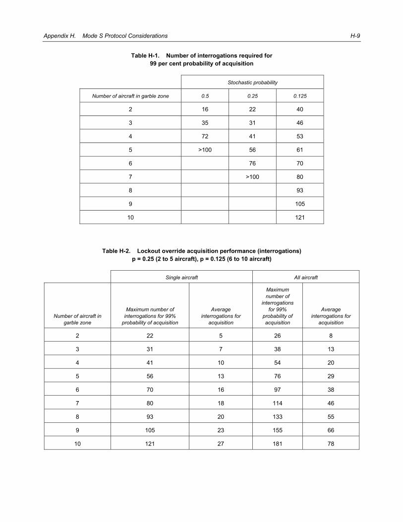
Appendix H. Mode S Protocol Considerations H-9
Table H-1. Number of interrogations required for 99 per cent probability of acquisition
Stochastic probability
Number of aircraft in garble zone 0.5 0.25 0.125
2 16 22 40
3 35 31 46
4 72 41 53
5 >100 56 61
6 76 70
7 >100 80
8 93
9 105
10 121
Table H-2. Lockout override acquisition performance (interrogations) p = 0.25 (2 to 5 aircraft), p = 0.125 (6 to 10 aircraft)
Single aircraft All aircraft
Number of aircraft in garble zone
Maximum number of interrogations for 99%
probability of acquisition
Average interrogations for
acquisition
Maximum number of
interrogations for 99%
probability of acquisition
Average interrogations for
acquisition
2 22 5 26 8
3 31 7 38 13
4 41 10 54 20
5 56 13 76 29
6 70 16 97 38
7 80 18 114 46
8 93 20 133 55
9 105 23 155 66
10 121 27 181 78

H-10 Aeronautical Surveillance Manual
2.1.3.2 1 030 MHz considerations The stochastic/lockout override technique uses a standard Mode S-only all-call and, therefore, has the same effect on the 1 030 MHz channel as the all-call generated by a standard Mode S interrogator. From a 1 030 MHz perspective, an interrogator using stochastic/lockout override could operate at the same all-call interrogation rate as a standard Mode S interrogator. 2.1.3.3 1 090 MHz considerations 2.1.3.3.1 A standard Mode S interrogator using lockout will only elicit all-call replies from Mode S aircraft just entering coverage, or those aircraft that have timed out of lockout due to failure to receive an interrogation in the last 18 ±1 second. A very high assumption for the number of aircraft not in the lockout state in a high traffic environment is about one aircraft per beam dwell, or a total of 120 aircraft for an interrogator with a standard 3-degree beamwidth (3 dB). Given a maximum specified all-call PRF of 250, this would yield a maximum of about 250 Mode S all-call replies per second per standard Mode S interrogator. 2.1.3.3.2 An interrogator using lockout override will have a higher reply rate to its all-call interrogations since lockout is not used. Assume an interrogator with a 10-second scan, a 3.6-degree beamwidth and 700 aircraft in track. The average beam loading will be seven aircraft for each of the 100 beam positions per scan. If a stochastic probability of 0.25 is used, there will be an average of around two replies to each all-call interrogation. 2.1.3.3.3 On this basis, the total all-call interrogation rate for this example interrogator using lockout override should be limited to about 125 Mode S-only all-call interrogations per second to avoid generating any more Mode S FRUIT than a standard Mode S interrogator. 2.1.3.3.4 Different target loadings, beamwidths and scan rates will lead to different operating points. However, the operating principle is to limit total Mode S all-call FRUIT to no more than the low level generated by a standard Mode S interrogator.
2.1.4 Example of interrogator use of lockout override
2.1.4.1 Interrogator characteristics Assuming that the interrogator has a beamwidth of 3.6 degrees, a range of 370 km (200 NM) and a scan time of 10 seconds, using 10 lockout override all-call interrogations per beam dwell leads to an interrogation rate of 100 per second. This is within the interrogation rate allowed by the SARPs, even after adjustment for the higher number of replies produced per interrogation. 2.1.4.2 Expected performance Table H-2 indicates the maximum and average number of interrogations needed to achieve a 99 per cent probability of acquisition. Since ten interrogations are used per beam dwell, the maximum and average number of scans for acquisition can be determined by dividing the last two columns of Table H-2 by ten and rounding up to the next whole scan. The result is shown in Table H-3.
5/4/12 No. 1

Appendix H. Mode S Protocol Considerations H-11
Table H-3. Stochastic/lockout override acquisition performance (scans) P = 0.25 (2 to 5 aircraft), p = 0.125 (6 to 10 aircraft)
Number of aircraft in the garble zone
Maximum number of scans for 99% probability of acquisition
Average number of scans for 99% probability of acquisition
2 2 1
3 3 1
4 4 1
5 6 2
6 7 2
7 8 2
8 9 2
9 10 3
10 11 3
2.1.4.3 Simulation results 2.1.4.3.1 The acquisition performance for an interrogator with the aforementioned characteristics was estimated by simulation. For the simulation, a traffic density of 10, 25 and 50 aircraft per beamwidth was generated randomly in range and azimuth out to 370 km (200 NM) at an extent of three beamwidths. Performance was measured for the aircraft in the centre beamwidth as the interrogator beam scanned through the traffic. The results are presented in Figure H-2. 2.1.4.3.2 An indication of the performance in terms of the number of aircraft acquired is shown in Figure H-3. It can be seen that for the 10 and 50 aircraft cases, all but one of the aircraft were quickly acquired, but the last aircraft was not acquired even after 20 scans.
2.1.5 Adaptive technique for reduced acquisition time
2.1.5.1 Need for an adaptive technique The simulation results show that while rapid acquisition is provided by lockout override for most aircraft, it may take a long time to acquire all aircraft in a high density environment. Acquisition performance can, however, be improved by the use of selective lockout. 2.1.5.2 Use of II = 0 2.1.5.2.1 The development of the Mode S subnetwork algorithms has greatly limited the utility of II code zero. The subnetwork communication protocols require the use of a non-zero II code in order to support downlink routing. Thus II = 0 will not be used when Mode S data link is used with the subnetwork services, even in areas of no overlapping sensor coverage.
5/4/12No. 1

H-12 Aeronautical Surveillance Manual
Figure H-2. Lockout override probability of acquisition
(3.6-degree beam, 10-second scan, 10 all-call interrogations per beam, p = 0.25) 2.1.5.2.2 Given that II = 0 will not be used in the most dense areas, it would seem that II = 0 could be eliminated for normal acquisition use without restricting Mode S operations. 2.1.5.3 Adaptive acquisition 2.1.5.3.1 For acquiring the last of the aircraft in a garble zone, an adaptive technique using II = 0 operates as follows: a) all of the acquired aircraft in the beam dwell of the garble zone containing the unacquired aircraft are
discretely interrogated and locked out to II = 0; b) during the following scan, all-call interrogations are transmitted using II = 0, without lockout override;
and c) transponders will unlock to II = 0, 18 seconds after the last lockout command. 2.1.5.3.2 The reduced garble density will lead to rapid acquisition of the unacquired aircraft, or a determination that it is not Mode S equipped. Since lockout is used only temporarily and selectively, only a minimum of coordination is required with neighbouring interrogators using lockout override to avoid conflict in the use of lockout to II = 0.
201510500.7
0.8
0.9
1.0
Number of scans
Probability of acquisition
Prob
abilit
y of a
cqui
sitio
n
Number of aircraft perbeam dwell
102550
5/4/12 No. 1

Appendix H. Mode S Protocol Considerations H-13
Figure H-3. Stochastic/lockout override number of aircraft acquired
(3.6-degree beam, 10-second scan, 10 all-call interrogations per beam, p = 0.25)
2.2 MODE S PASSIVE ACQUISITION
2.2.1 Need for passive acquisition 2.2.1.1 From the initial design to the present day, all Mode S scanning-beam interrogators have used an active approach (all-calls plus lockout) to acquire Mode S aircraft as described in 1.1 to 1.5 of this Appendix. This approach has two disadvantages: a) it results in unnecessary all-call replies from aircraft beyond the interrogator’s operating and lockout
range; and b) active acquisition requires the assignment of an II or SI code selected to permit non-conflicting lockout
operation with all neighbouring Mode S interrogators that have overlapping coverage. Passive acquisition’s ability to provide significant reduction in all-call fruit (especially in areas where many Mode S interrogators are installed) and its ability to operate a Mode S interrogator without the need for an assigned interrogator code are both reasons for considering the use of this technique. The following paragraphs provide more detail on the advantages of operating without an assigned interrogator code.
201510500
20
10
40
30
50
Number of scans
Number of aircraft acquired
Number of aircraft perbeam dwell
102550
5/4/12No. 1

H-14 Aeronautical Surveillance Manual
2.2.1.2 The initial Mode S design had a total of 15 assignable interrogator codes (II Codes). As Mode S was implemented, it became necessary to increase the number of assignable interrogator codes, so a revision was made that added an additional 63 interrogator codes (SI Codes) for a total of 78 interrogator codes. 2.2.1.3 In the highest interrogator density in Europe, even this increased number of codes requires careful assignment in order to meet surveillance requirements that all overlapping coverage areas be assigned to different interrogator codes. 2.2.1.4 Mobile interrogators create a special challenge for the assignment of interrogator codes. These interrogators in particular can benefit from the use of passive acquisition of Mode S aircraft due to the ability to operate without an assigned interrogator code. 2.2.1.5 This section provides guidance on the use of passive techniques to acquire Mode S aircraft. Note that the passive acquisition system will develop information on aircraft being acquired that will have to be input and processed by the serviced Mode S interrogator. Mode S interrogators equipped with an interface for cluster operation can be interfaced with a passive acquisition system with little or no modification. More extensive modification will be required for existing Mode S interrogators without a cluster interface. (See the Explanation of Terms and 1.5 of this Appendix for more details on cluster operation.)
2.2.2 Mode S transmissions available for passive acquisition Mode S transponder transmissions from airborne aircraft that can serve as the basis for passive acquisition are the following: a) Mode S Acquisition Squitter: This 56-bit Mode S waveform is spontaneously transmitted approximately
once per second by all Mode S transponders. This squitter is the principal means of Mode S acquisition by ACAS systems. It contains the 24-bit ICAO address as data and is protected by error detection and correction coding. The acquisition squitter has the same format as the Mode S only all-call reply. See Annex 10, Volume IV, Figure 3-8 for the data format of this transmission.
b) Mode S Extended Squitter (ES): 112-bit ES transmissions are spontaneously generated by Mode S
aircraft equipped for ES ADS-B. For airborne aircraft, the basic ES transmissions consist of 2 ES Airborne Position and 2 ES Airborne Velocity Squitters per second, plus one ES Identity and Category squitter per five seconds for a total of 4.2 per second as a minimum for ES-equipped aircraft. As for the acquisition squitter, the 24-bit ICAO address (as well as the ADS-B data) is protected by error detection and correction coding. See the Technical Provisions for Mode S Services and Extended Squitter (Doc 9871) for details of the data content of ES transmissions.
c) Mode S Replies to Addressed Interrogations: Mode S replies to addressed interrogations elicited from
ACAS or nearby ground Mode S interrogators can also be used for passive acquisition. The 24-bit ICAO address is not contained in the message data but must be derived from the address/parity field. An error in the decoding of the message will result in a modified 24-bit address. Special processing is required to confirm a 24-bit address reception based on address correlation with future reply receptions. See Annex 10, Volume. IV, Figure 3-8 for the data formats of the replies to addressed interrogations.
2.2.3 Independence requirement for passive acquisition A technique for passively acquiring a Mode S aircraft’s 24-bit ICAO address and its position must have the same independence as active acquisition. For example,
5/4/12 No. 1

Appendix H. Mode S Protocol Considerations H-15
a) ADS-B extended squitter can provide passive reception of the 24-bit address and position, but this technique is dependent on the ES reported position for successful acquisition. If the reported position is accidently (or intentionally) incorrect, the Mode S interrogator would not be able to acquire the aircraft. Aircraft not equipped with ES would also not be able to be acquired. Hence, ES is not an acceptable primary acquisition technique for a Mode S interrogator.
b) A wide area multilateration (WAM) system can provide a very accurate position estimate in addition to
the 24-bit address based on acquisition or extended squitters. However, using such WAM data for Mode S acquisition would mean that the Mode S interrogator could not be considered independent of the MLAT system for system availability purposes. That is, a failure of the MLAT system would result in a failure of the Mode S interrogator. Therefore, a WAM system is not a suitable primary acquisition technique for a Mode S interrogator.
2.2.4 Information requirements for passive acquisition 2.2.4.1 Using active acquisition, a Mode S interrogator obtains the range, azimuth and 24-bit ICAO address from aircraft replies to Mode S only all-call interrogations. On a subsequent scan, the interrogator includes discrete interrogations addressed to the newly acquired aircraft at the azimuth and range obtained from the previous all-call replies. As shown in Figure H-4, discrete interrogations are formed into a tightly packed schedule to efficiently use the available dwell time.
Figure H-4. Mode S discrete interrogation and reply scheduling
2.2.4.2 Efficient scheduling requires knowledge of the range of the newly acquired aircraft. Efficiency is important in order to make the best use of the available dwell time. After a successful initial discrete interrogation, regular roll call surveillance is performed using all-call lockout so that all-call replies from other aircraft entering the coverage area are not garbled by all-call replies from already acquired aircraft. 2.2.4.3 A passive system for Mode S acquisition must as a minimum provide the 24-bit ICAO address and an azimuth estimate. The azimuth estimate must be accurate enough to place the acquired aircraft in one or two beam widths of the Mode S interrogator so that subsequent addressed interrogations can be made over a limited angle to reduce interference. The typical beam width for a Mode S interrogator is nominally 2.4 degrees. 2.2.4.4 The recommended technique for passive Mode S acquisition is a short-baseline multilateration (MLAT) system installed and operated near the interrogator. General details of MLAT system are provided in Chapter 5, 5.3.5 and Appendix L. 2.2.4.5 In cases where an MLAT array is not feasible (e.g. on a ship) an alternative technique that can be used is an omnidirectional antenna with angle of arrival (AOA) capability. This omni antenna can be placed at the centre of an electronically scanned antenna or placed near a scanning beam Mode S interrogator.
(A)
1 2 3 41 2 3 4
REPLIES
INTERROGATIONS
5/4/12No. 1

H-16 Aeronautical Surveillance Manual
2.2.4.6 The above techniques can provide the 24-bit ICAO address and accurate azimuth but cannot provide accurate range without augmentation. Accurate range is very useful since it results in very efficient interrogation scheduling as shown in Figure H-4. 2.2.4.7 A description and expected performance of the short baseline MLAT system and the AOA approach are provided in the following sections. This is followed by sections on augmentation techniques to obtain range so that normal interrogation scheduling can be used, and also scheduling techniques if range is unknown.
Figure H-5. Short baseline MLAT receiver configuration
2.2.5 Short baseline MLAT system for passive acquisition 2.2.5.1 Configuration: Figure H-5 shows the configuration for a 4 receiver 3D multilateration system with a 100 m baseline. The interrogator would be located near the central receiving station. 2.2.5.2 Error Characteristics: Multilateration errors are normally expressed in terms of x and y but if they are expressed in terms of range and azimuth a useful characteristic of a multilateration system becomes apparent that is directly applicable to its use for passive Mode S acquisition. As will be shown, the azimuth error is relatively small but the error in range increases significantly once the target is outside the area of the receivers. 2.2.5.3 Azimuth Error: Figure H-6 shows how the error of a 4 receiver 3D multilateration system varies for a 100 m baseline system. It can be seen that the bearing accuracy is accurate to a fraction of a bearing error in degrees. This shows excellent accuracy, typically 0.2 to 0.3 degrees. 2.2.5.4 Range Error: Figure H-7 shows a slice through the area indicating how the range accuracy changes throughout the region. Note that the range accuracy degrades rapidly outside the area enclosed by the receiver stations. It is seen that the range error exceeds 1 NM very rapidly outside the coverage area. For this 100-m baseline scenario the range error caused by a nominal (1 ns) timing error exceeds 1 NM beyond 3 km from the centre.
5/4/12 No. 1

Appendix H. Mode S Protocol Considerations H-17
Figure H-6. Azimuth accuracy of a 100 m baseline multilateration system
Figure H-7. Range and azimuth accuracy cuts for a 100 m baseline multilateration system
250
200
150
100
50
0
-50
-100
-150
-200
-250-250 -200 -150 -100 -50 0
NM50 100 150 200 250 0
0.1
0.2
0.3
0.4
0.5
0.6
0.7
0.8
0.9
1(degrees) per ns errorΘσ
-300 -200 -100 0NM
100 200 300
16
14
12
10
8
6
4
2
0
x 106
(met
res)
per
ns
erro
r
σo Ra
nge
5/4/12No. 1
H-18 Aeronautical Surveillance Manual
2.2.6 Angle of arrival antenna (AOA) for passive acquisition 2.2.6.1 Configuration: For passive acquisition, a six-sector omnidirectional antenna will be used with a receiver and Mode S reply processor attached to each sector giving continuous 360 degree coverage. AOA is performed by using a monopulse technique based on the relative amplitude of the received signal on adjacent beams. 2.2.6.2 Detailed Antenna Characteristics: Antenna and physical specifications for the six-sector antenna are as follows: Azimuth coverage: 60° Nominal for each lobe. Peak of beam gain: > 16 dBi. Gain: > 13 dBi throughout 60° sector including edges. Size: 2.5 m high by 0.6 m in diameter. Weight: Approximately 115 kg. Physical design: Six radiating arrays backed by six reflector elements. Entire RF portion is protected
by a radome. 2.2.6.3 AOA Measurement Technique: To measure the AOA performance for this antenna system, the squitters from two aircraft that were at a range of more than 200 NM were received and recorded. One of the aircraft (the target) was used to derive a direction-finding calibration curve, defining the azimuth offset of the target aircraft as a function of the difference in the power received by the two adjacent antenna channels for each squitter. Then the power levels in the two adjacent antenna channels of the squitters received from the other aircraft were used to evaluate the use of this calibration curve to measure its azimuth. 2.2.6.4 Measured AOA Results: Using this calibration curve to estimate the azimuth of the target aircraft from the power differences in the two adjacent channels, the RMS error was 3.2 degrees. In a more realistic test, when the calibration curve is applied to the power differences of the squitters received from the other aircraft, the RMS error was 4.2 degrees. However, if 7-point smoothing is applied to the power differences before using the calibration curve to estimate azimuth, the RMS error reduces to 1.9 degrees. 2.2.6.5 Performance Evaluation: The measured AOA performance was based on a once-per-second transmission for aircraft at long range. When used on a single one-second measurement, the AOA performance was 4.2 degrees. With smoothing this error was reduced to 1.9 degrees. Smoothing could be used on the higher squitter rate for aircraft equipped with ES to further reduce this error. Even without any smoothing, the measured AOA performance is sufficient to locate the aircraft to within the required two antenna beam widths. Note that this technique by itself provides no range information.
2.2.7 Augmentation techniques to obtain range 2.2.7.1 Mode S Interrogator Transmitter 2.2.7.1.1 A technique can be employed to measure the range of aircraft to augment the azimuth-only information obtained from the short baseline MLAT or AOA systems. This approach is particularly attractive if the Mode S interrogator is equipped with an interface for clustered interrogator operation. (See the Explanation of Terms and 1.5 of this Appendix for more details on cluster operation.) When so equipped, a Mode S interrogator can be used to provide active range augmentation without any modification to the Mode S interrogator. The passive acquisition system will measure the azimuth of Mode S targets within radar coverage and maintain a track list of targets. Any measurement with
5/4/12 No. 1

Appendix H. Mode S Protocol Considerations H-19
a 24-bit address not on the track list is a newly acquired aircraft. The cluster interface will be used to instruct the radar to roll-call the aircraft being acquired at the correct azimuth but with a nominal range. In parallel the passive acquisition system will receive the interrogation and record the interrogation and reply times for this 24-bit address and calculate the range to the target. The cluster interface will then be used again to provide the correct position for the aircraft allowing the radar to acquire it using roll-call. This technique could also be used by modifying Mode S interrogators that do not have a cluster controller interface. 2.2.7.1.2 Note that the use of this technique requires a 1 030 MHz receiver, a Mode S interrogation processor and accurate time tagging of the interrogation and reply. 2.2.7.2 Standalone Transmitter 2.2.7.2.1 For AOA-based passive acquisition systems the alternative exists to use a single transmitter that can be switched to any of the six sectors to make range measurements independent of the collocated Mode S interrogator. The system will transmit an interrogation to the aircraft to be acquired and measure its range. The 24-bit address, bearing and range will then be input to the Mode S interrogator for roll-call surveillance. 2.2.7.2.2 Note that this technique requires a 1 030 transmitter and a Mode S interrogation processor plus accurate time tagging of the interrogation and reply. 2.2.7.2.3 ES Reported Position: Available ES position can be used to obtain range for a short baseline or AOA system with or without active range augmentation. In the case that active range augmentation is used, the ES position will reduce the frequency of active interrogations and thereby reduce interference effects. In order to guard against acceptance of incorrect ES position data, the bearing derived from the ES data must be compared to that measured by the short baseline MLAT or AOA systems. If there is a discrepancy, the ES data will be discarded. 2.2.7.2.4 WAM Position: Available WAM positions can be used to obtain range for a short baseline or AOA system with or without active range augmentation. In the case that active range augmentation is used, the WAM position will reduce the frequency of active interrogations and thereby reduce interference effects.
2.2.8 Scheduling addressed acquisition interrogations 2.2.8.1 Scheduling with a Range Estimate: If range is available in the acquisition information provided to the Mode S interrogator, the standard technique for interrogation and reply scheduling can be used (as shown in Figure H-4). 2.2.8.2 Scheduling without a Range Estimate 2.2.8.2.1 If no range estimate is available, a different approach to scheduling is required to avoid garble of addressed acquisition replies due to the unknown time at which the reply will be received. An interrogator using active surveillance separates the channel timeline into distinct periods for roll call and combined Mode A/C and Mode S all-call periods as shown in Figure H-8. An interrogator using passive surveillance will only perform Mode A/C surveillance in these periods. This presents an opportunity to use the Mode A/C periods for acquisition of Mode S aircraft whose range is unknown.
5/4/12No. 1

H-20 Aeronautical Surveillance Manual
Figure H-8. Mode S interrogator channel periods
2.2.8.2.2 The approach is to schedule one or more addressed acquisition interrogations at the beginning of the Mode A/C period. Since the short P4 pulse will be used with Mode A/C interrogations, only non-Mode S aircraft will reply. This will ensure a low probability of addressed reply loss due to Mode A/C replies overlapping the addressed Mode S reply. If only one addressed interrogation is transmitted in a Mode A/C period, then the reply should be received with high probability since the Mode S error correction coding is optimized for decoding in the presence of a single Mode A/C overlap. In some cases it may be necessary to attempt acquisition of more than one Mode S aircraft in a single Mode A/C period (e.g. recovery of the track files after a period of interrogator failure). In this case, it is possible to have occurrences of overlapping Mode S replies. Successful decoding of overlapping Mode S replies is a much lower probability event. 2.2.8.2.3 The receipt of a Mode S reply that cannot be error corrected is an indication of a garble condition of two or more Mode A/C replies with the Mode S acquisition reply, or two (or more) overlapping Mode S replies. If this condition happened during normal all-call processing, the remedy would be to use the stochastic acquisition feature to command a reply probability of less than one to obtain a reply from only one of the aircraft of the garbling set. Reply probability cannot be commanded for an addressed interrogation, but scheduling another acquisition interrogation in the next Mode A/C period using a different relative interrogation time will achieve the same effect. 2.2.8.2.4 Once a successful reply is received to an acquisition interrogation, future addressed interrogations can be incorporated into the normal roll-call schedule.
2.2.9 Summary 2.2.9.1 This section has described a concept for passive acquisition of Mode S aircraft by a scanning beam Mode S interrogator. The benefit of passive acquisition is reduced all-call fruit and the ability to operate without an assigned interrogator code. Two techniques were described for obtaining the aircraft 24-bit ICAO address and bearing; a short baseline MLAT and an AOA antenna system. These systems can be augmented with active interrogation together with ES or WAM position to obtain range data. Two techniques for acquisition interrogation scheduling were described for the cases with or without range data. 2.2.9.2 The described technique for using the Mode S interrogator to obtain range is most attractive for adding passive acquisition to an interrogator with a cluster interface. The availability of this interface makes it possible to integrate passive acquisition capability with little or no modification to the Mode S interrogator.
BEAM DWELL TIME
ATCRBS/MODE S ALL-CALL PERIODS
TIME
MODE S ROLL CALL PERIODS
5/4/12 No. 1

Appendix H. Mode S Protocol Considerations H-21
3. SURVEILLANCE PROTOCOL 3.1 The ground station’s surveillance protocol should routinely elicit Mode C altitude in the Mode S surveillance reply. An additional interrogation to elicit the aircraft Mode A code should also be sent: a) when the Mode S aircraft is acquired; b) after a prolonged coast period; and c) in the case of temporary or permanent alert. 3.2 An alert condition is reported in the FS field of every surveillance and Comm-B reply to indicate a change in Mode A code. If the new code is an emergency code (7500, 7600 or 7700), the alert condition remains active (i.e. it does not time-out). If the new code is not an emergency code, the alert condition resets after 18 (plus or minus 1) seconds. The interrogator should continue to elicit a Mode A response for one to two scans after the alert condition clears to ensure steady state reliability. 3.3 Knowledge of the current value of the transponder Mode A code is important to the ATC system since: a) the code is used to signal emergency conditions; and b) it is needed to identify an aircraft in handoffs to non-Mode S facilities. 3.4 Provision is therefore made in the FS field to notify the ground station when the Mode A code is changed during the flight.
4. UPLINK SLM DATA LINK PROTOCOL (COMM-A) Note.— Comm-A interrogations are used for the ground-to-air transmission of SLMs. Before any such transfer is initiated, the interrogator has knowledge (from a previous capability report usually obtained when the aircraft is first acquired) of the Comm-A capability of the addressed aircraft.
4.1 COMM-A protocol precautions 4.1.1 If the transponder cannot pass the uplink SLM to the data link processing unit, it may not reply to that Comm-A interrogation. Some transponders are designed not to accept an interrogation if they cannot output the uplink message. However, a transponder in this state will continue to respond to short surveillance interrogations. In the event of loss of contact with an aircraft when using only Comm-A interrogations, a ground station should transmit one or more short interrogations to determine whether interface failure is preventing the transponder from replying. A change of data link capability is announced by the broadcast Comm-B message. 4.1.2 If separate transponder interfaces are used for ACAS and ADLP, the transponder must route selectively addressed Comm-A messages to the appropriate interface based on information in the Comm-A interrogation. Comm-A messages intended for ACAS are identified by DI = 1 or 7, TMS = 0 and the first eight bits of the MA field equal to 05 HEX. Messages identified for ACAS (including air-air MU messages) should be delivered to the ACAS interface but not to the ADLP interface. Messages that are not identified for ACAS should be delivered to the ADLP interface but not to the ACAS interface.
5/4/12No. 1

H-22 Aeronautical Surveillance Manual
4.2 COMM-A broadcast messages Comm-A broadcast messages are intended for the transfer of a message to all aircraft within an azimuth sector. Depending upon operational needs, this sector can be as small as one beamwidth, or as large as a complete antenna rotation. Because of the absence of a transponder reply, the interrogator will not have positive confirmation that this message was received by a particular aircraft. For this reason, broadcast messages should be restricted to information that is retransmitted periodically in order to ensure a high probability of successful delivery. Comm-A broadcast messages should be transmitted at a rate that allows at least three transmissions within each azimuth sector corresponding to the antenna 3-dB beamwidth. This minimum transmission rate ensures a reasonable probability of delivering the broadcast Comm-A message in one antenna scan.
5. DOWNLINK SLM DATA LINK PROTOCOL (COMM-B)
5.1 Ground-initiated transfer of Comm-B messages 5.1.1 The GICB protocol allows for the immediate transfer of data required by the ground and the extraction of information stored in the transponder. This information (if available) is contained in the reply to an interrogation specifying the address (BDS code) of the storage location containing that information. Examples of information obtainable using the GICB protocol are “data link capability report” and “aircraft identification”. An example of a GICB message delivery is presented in Table H-4. 5.1.2 Airborne applications providing downlink data via the GICB protocol will update specific registers at a rate that is consistent with maintaining current information in those registers. A minimum rate of approximately 5 seconds is used to provide for recovery of the GICB register data in the event of a failure that causes the transponder to lose GICB data. If an interface used to load the GICB registers fails, the data in the registers will become invalid with no indication given to users of these messages. Transponder action in this case should be to clear those GICB registers being updated by this interface, with the exception of the data link capability Register (1016). This register has a special protocol for failure detection. Upon recovery of this interface, the airborne applications will resume loading data into these registers. Recovery will be completed in approximately 5 seconds.
Table H-4. Example of GICB delivery of Register 3516
Interrogationa Replya Relevant fields Significance
S or A RR = 19b GICB message with BDS1 = 3
DI = 7 SD field contains RRS
RRS = 5 BDS2 of requested Comm-B message
B MB GICB message
Notes: a) S = surveillance (UF = 4, 5), A = Comm-A (UF = 20, 21), B = Comm-B (DF = 20, 21). b) RR code value equals 16 plus the decimal value of BDS1.
5/4/12 No. 1

Appendix H. Mode S Protocol Considerations H-23
5.1.3 If the transponder interface used to load the AIS in GICB Register 2016 fails, the transponder should clear the AIS and the AIS bit in the data link capability report. This will cause the transponder to broadcast a change in aircraft ID and a change in data link capability. This action can be independent from the general clearing of the GICB registers if a separate interface is used to load the GICB Register 2016. The transponder will ensure that the BDS code 2,0 (bits 33–40) is set in the resulting Comm-B broadcast message. 5.1.4 ACAS will normally be provided with a separate transponder interface. The same protocol for clearing GICB registers in the event of an interface failure should be applied separately to the ACAS interface. 5.1.5 The transponder action, in the event of an interface failure, is a function of the type of data transferred by that interface. For example, if GICB and SLM data use separate interfaces, the transponder will be able to provide GICB data even in the event of an SLM interface failure. Since the SLM interface is used by the ADLP to load the data link capability report, failure of the SLM interface will cause this report to indicate zero data link capability even though the transponder is still capable of supporting the transfer of GICB data. 5.1.6 The readout of a GICB can occur at any time, since it is governed by the transmission time of the interrogators. These interrogations involve an access to the GICB registers. A second asynchronous activity involving register access is the process of updating the information in the GICB registers. It is important that safeguards be provided to ensure that a register update cannot occur during an access due to a received interrogation. This will avoid the error of providing data from a partially updated register in the reply to a GICB request.
5.2 Air-initiated transfer of COMM-B messages
5.2.1 COMM-B message announcement and closeout 5.2.1.1 An air-initiated Comm-B message waiting for delivery causes the DR code of every surveillance or Comm B reply to be set to a value that indicates that an AICB message is waiting. To extract the Comm-B message, the ground station will transmit a request for a Comm-B message reply in a subsequent interrogation (RR = 16 and if DI = 7, RRS = 0). Reception of this request code will cause the transponder to transmit the Comm-B message. The Comm-B reply will continue to contain a DR code equal to ONE. The message will be cancelled and the DR code belonging to this message will be removed once a Comm-B closeout has been received. 5.2.1.2 This protocol can result in the reception of more than one Comm-B closeout instruction for a particular message if the interrogation containing the closeout is received by the transponder, but the ground station does not receive the reply. The absence of the expected reply will cause the ground station to repeat the interrogation at the next opportunity. 5.2.1.3 If the transponder has a second AICB message waiting to be transferred, it indicates its presence to the ground station by sending the appropriate DR code in its reply to the interrogation that delivered the Comm-B closeout acknowledgement to the previous message. Every effort should be made to deliver this closeout within the same beam dwell period as the message delivery in order to permit the announcement of subsequent messages waiting to be delivered. Note that the avionics must not permit a message to be closed out until after it has been read at least once. This prevents the multiple clears that can be received due to a downlink failure from closing out a second waiting message that has not as yet been transferred to the ground station. The possibility of downlink failure also prohibits the ground station from both reading and closing out a Comm-B message in the same interrogation because multiple delivery of such an interrogation could result in the loss of an undelivered Comm-B message.
5/4/12No. 1

H-24 Aeronautical Surveillance Manual
5.2.2 Multisite transfer of AICB messages 5.2.2.1 In a multisite environment, an AICB message may be read by more than one ground station. In this protocol, any ground station is allowed to read the air-initiated message, but only the ground station that made a prior reservation may close out the message. 5.2.2.2 If it is possible for more than one ground station to service an AICB message request, the multisite protocol or ground coordination must be used to avoid possible loss of messages. Such a loss can occur when: a) a transponder has more than one air-initiated message ready for delivery; b) the interleaved read and cancel instructions from the multiple sites results in the following sequence: i) ground station A has cleared message 1 and has had a downlink failure in reading message 2;
and ii) this is followed by a cancel from ground station B (intending to cancel message 1) that in fact
cancels message 2, which is lost since it has not been successfully read by either ground station. 5.2.2.3 When the ground station extracts an air-initiated message, normally after having made a reservation, it must check the UM field to determine whether it is the reserved site for this message. When this is the case, the message will be processed and closed out by this ground station in a subsequent interrogation, before the reservation expires. When another ground station is already reserved for the message, the announcement for this message may be ignored. 5.2.2.4 In a multisite environment, more than one ground station can attempt to extract an AICB message. Normally, the first one to attempt to extract the message will be the one that is reserved for processing and closeout of the message. 5.2.2.5 Multisite closeout of an AICB message can be accomplished in two ways: a) through coding in the MBS of the SD field; or b) through coding in the PC field. 5.2.2.6 In either case, closeout will be accomplished by the transponder only if the II code of the interrogator that delivers the closeout command matches the II code reserved for that message. 5.2.2.7 An example of a multisite AICB message delivery is presented in Table H-5.
5.2.3 Multisite-directed Comm-B delivery 5.2.3.1 This multisite Comm-B protocol makes it possible for the ADLP to route an air-initiated message to a particular ground station. This capability is important in a multisite environment since it makes it possible for a pilot acknowledgement message to be routed to the ground station that delivered the message being acknowledged. 5.2.3.2 When a Comm-A message is delivered, the ADLP will receive the SD field along with the MA field, and will thus be able to associate the sending site address in the IIS with the Comm-A message. When a pilot acknowledgement is generated, the ADLP will cause the transponder to reserve the message for the desired site address at the same time that the message is made available for delivery. Thus, even the initial reply indicating that an AICB message is waiting will show (in the UM field) that a reservation already exists for the desired site. This reservation
5/4/12 No. 1

Appendix H. Mode S Protocol Considerations H-25
remains in effect until the message is read and closed out by the reserved ground station, or until the message is cancelled by the ADLP.
Table H-5. Example of multisite AICB delivery
Interrogationa Replya Relevant fields Significance
S or A — —
S or B DR = 1 AICB waiting
S or A RR = 16 Readout of AICB
DI = 1 Multisite SD field
MBS = 1 Comm-B reservation
RSS = 1 Request for Comm-B reservation status in UM
IIS = 4 Local site’s II
B DR = 1 AICB waiting
IDS = 1 Comm-B reservation status in IIS
IIS = 4b Site 4 (the local site) is the reserved site
MB Contains the air-initiated message
S or A DI = 1 Multisite SD field
MBS = 2 Multisite Comm-B closeout
IIS = 4 Local site’s II
S or B DR = 0c Comm-B closed out (IIS field is also cleared in the transponder)
Notes: a) S = surveillance (UF = 4, 5), A = Comm-A (UF = 20, 21), B = Comm-B (DF = 20, 21). b) If IIS = 4, the local site is not the reserved site, and no further action is taken on the message. c) If DR = 1 in the reply to a Comm-B closeout, it indicates the presence of another air-initiated Comm-B message.
5.2.4 Non-selective transfer of AICB messages The non-selective protocol is used if: a) the ground station does not have overlapping coverage with any other Mode S ground station; or b) it communicates with its neighbouring ground stations to ensure that only one ground station at a time
is responsible for Comm-B message transfer. A reservation is not required in the non-selective protocol. Closeout is accomplished through coding of the PC field. An example of a non-selective AICB message delivery is presented in Table H-6.
5/4/12No. 1

H-26 Aeronautical Surveillance Manual
Table H-6. Example of non-selective AICB delivery
Interrogationa Replya Relevant fields Significance
S or A — —
S or B DR = 1 AICB waiting
S or A RR = 16 Readout of AICB
DI = 7 No extended data readout
DI = 7 and LOS = 0
No extended data readout
DR = 1b AICB message waiting
B MB AICB message
S or A PC = 4 Non-selective Comm-B closeout
S or B DR = 0c Comm-B closed out
Notes: a) S = surveillance (UF = 4, 5), A = Comm-A (UF = 20, 21), B = Comm-B (DF = 20, 21). b) The message has not yet been closed out. c) If DR = 1 in the reply to an AICB closeout, it indicates the presence of another air-initiated Comm-B message.
5.2.5 AICB error recovery 5.2.5.1 If a multisite-directed Comm-B message is input to the transponder by the ADLP, this message can only be cleared by: a) the interrogator after a successful delivery; or b) ADLP action after a timeout if the message is not delivered, since multisite-directed message
reservations do not time out in the transponder. If the transponder SLM interface fails while a multisite-directed Comm-B message is awaiting delivery, no other Comm-B activity can occur until the multisite-directed message is delivered. An undeliverable multisite-directed message will block any further Comm-B activity by the transponder. This includes the Comm-B broadcast of the change of data link capability report that the transponder will initiate to inform the ground of loss of communication capability because of the SLM interface failure. 5.2.5.2 In the event of SLM interface failure, the transponder should clear any waiting air-initiated messages and notify the ADLP of this action when the interface operation is restored. Whenever ADLP operation is initiated at power-up or resumed after recovery from a failure, the ADLP should clear the transponder AICB registers.
5.3 Broadcast COMM-B 5.3.1 The AICB protocol described above is designed to deliver a Comm-B message initiated on board an aircraft to a single ground station. Certain types of messages may require delivery to more than one ground station. In this case the broadcast Comm-B message protocol is used.
5/4/12 No. 1

Appendix H. Mode S Protocol Considerations H-27
5.3.2 The broadcasting of Comm-B messages should be strictly controlled and limited to those messages that are required to be received by all ground stations that have the aircraft in coverage. For example, a change in the data link capability would be delivered by a broadcast Comm-B message. The broadcast Comm-B message should never be used for messages that are intended to elicit a subsequent response from a single ground station as this would result in multiple delivery of the requested response, one from each ground station that reads the broadcast message. 5.3.3 The broadcast Comm-B protocol uses the DR field to signal the presence of a broadcast Comm-B message that is available for delivery. Any ground station in contact with the transponder may read the message using the same coding as for an AICB message. The key difference is that the ground station cannot clear a broadcast message; the message clears automatically after approximately 18 seconds. During the period when the message is active, it can be read by every ground station in contact with the transponder. 5.3.4 Provision is made in the coding of the DR field to distinguish two different broadcast messages, i.e. broadcast message 1 and broadcast message 2. The transponder will send successive broadcast messages using alternate message codes. This permits the ground station to detect the change in a broadcast message and therefore eliminates the need for the ground station to read the message at every scan. Thus, a ground station that has read broadcast message 1 from a particular transponder on one scan can safely avoid reading the same message on subsequent scans (until it times out) since the presence of a new broadcast message will be indicated by DR = 5, i.e. “broadcast message 2 is available”. 5.3.5 Provision is made for an AICB message to interrupt the delivery of a broadcast Comm-B message. In this case, the broadcast message delivery is resumed for the full 18-second period following the delivery of the air-initiated message. In the case of a queue of AICB messages, the delivery of a broadcast message may take considerably longer than 18 seconds. 5.3.6 The transponder is required by the broadcast protocol to provide a delivery notice to the data link interface upon timeout of a broadcast message. This is used by the ADLP to update its message processing bookkeeping. The transponder can initiate two broadcast messages: a) a change in transponder capability; and b) a change in aircraft ID — the ADLP is not aware of the presence of these messages. Therefore, it is unnecessary for the transponder to generate delivery notices for these transponder-initiated broadcast messages.
6. UPLINK ELM DATA LINK PROTOCOL Note.— The uplink ELM protocol provides for more efficient transmission of long data link messages by permitting the grouping of up to 16 80-bit message segments into a single entity that can be acknowledged by a single reply. Each segment is included in a single Comm-C transmission. The limit of 16 segments refers solely to the manner in which the message is transferred over the link. Longer messages can be accommodated through the use of M-bit sequencing of packets within the Mode S subnetwork.
6.1 Basic uplink ELM protocol Uplink extended-length messages are transmitted using the Comm-C format with three different reply control codes. The three reply control codes designate an initializing segment, intermediate segments and a final segment. The minimum length of a ground-to-air ELM is two segments since the protocol requires at least an initializing and a final segment. The transfer of all segments may take place without any intervening air-to-ground replies, as described in the following
5/4/12No. 1

H-28 Aeronautical Surveillance Manual
paragraphs. In this way, channel loading is minimized. Message segments (one per Comm-C interrogation) may be transmitted at any rate up to one per 50 microseconds. This limit on the minimum spacing is required to permit the re-suppression of Mode A/C transponders. Delivery of the message may take place during a single scan or over a few scans depending on the length of the message and the ground station loading. Normally, sufficient time will be available within one scan to permit complete delivery of the message.
6.2 Multisite uplink ELM protocol 6.2.1 The multisite uplink ELM protocol is used to coordinate the activities of multiple ground stations so that only one ground station at a time is reserved for uplink ELM activity. Before beginning an uplink ELM, a ground station uses the multisite protocol to obtain a reservation. 6.2.2 A reservation remains in effect for 18 (plus or minus one) seconds from the time of last delivery activity, i.e. the reservation itself or any segment delivery or acknowledgement request. If delivery activity ceases for more than 18 (plus or minus 1) seconds before delivery is complete, it is assumed that the ground station is no longer in contact and, the reservation is cancelled along with any segments that have been delivered up to that point. The transponder is then able to grant a reservation to any other ground station that is currently in contact. 6.2.3 Multisite uplink ELM closeout can be accomplished in either of two ways: a) through coding in the MES of the SD field; or b) through coding in the PC field and SD fields. Every effort should be made to deliver the closeout within the same beam dwell period as the completion of message delivery in order to make transponders available to other interrogators for uplink ELM delivery. It is not advisable to attempt the delivery of two uplink ELMs in the same beam dwell. This increases the probability of the second message not being completed. An example of a multisite uplink ELM delivery is presented in Table H-7.
6.3 Non-selective uplink ELM protocol 6.3.1 The non-selective protocol may be used when only one ground station at a time has the responsibility for delivering an uplink ELM message. No reservation is required. A partially delivered non-selective uplink ELM is not automatically cleared by a timeout. It is recommended that a ground station precede the first uplink ELM delivery to a newly acquired aircraft with an uplink ELM closeout to ensure that the transponder uplink ELM registers are cleared. 6.3.2 Ground stations with overlapping coverage that do not properly coordinate their communications activity through the use of the multisite protocols or ground coordination may experience the following communications failure modes: a) a multisite uplink ELM transaction in progress by one interrogator can be interfered with through the
action of another interrogator delivering an uplink ELM using the non-selective protocol. The transponder will accept uplink ELM segments as though they were being delivered by a single interrogator using the uplink delivery protocol. In this case, the completed message will be composed of segments from both ground stations; or
b) if an interrogator is delivering segments of an uplink ELM using the non-selective protocol, these
segments will be discarded upon receipt of an initializing segment from a second ground station.
5/4/12 No. 1

Appendix H. Mode S Protocol Considerations H-29
Table H-7. Example of multisite uplink ELM delivery
Interrogationa Replya Relevant fields Significance
S or A D = 1 MES = 1 RSS = 2 IIS = 6
Multisite SD field Uplink ELM reservation Request for uplink ELM reservation status in UM Local site’s II
S or B IDS = 2 IIS = 6b
Uplink ELM reservation status is in IIS Site 6 (the local site) is the reserved site
C RC = 0 NC = 2 MC
Initializing segment delivery Announces a 3-segment ELM Segment 3 of uplink ELM
None Reply not elicited by RC = 0
C RC = 1 NC = 1 MC
Intermediate segment delivery Indicates MC contains segment 2 Segment 2 of uplink ELM
None Reply not elicited by RC = 1
C RC = 2 NC = 0 MC
Segment delivery and request for technical acknowledgement Indicates MC contains segment 1 Segment 1 of uplink ELM
D KE = 1 TASc
MD contains technical acknowledgement of uplink ELM in TAS 1 to 3
S or A DI = 1 MES = 2 IIS = 6
Multisite SD field Multisite uplink ELM closeout Local site’s II
S or B Technical acknowledgement of closeout command
Notes: a) S = Surveillance (UF = 4, 5), A = Comm-A (UF = 20, 21), B = Comm-B (DF = 20, 21), C = Comm-C (UF = 24), D = Comm-D (DF = 24). b) If IIS = 6, the local site is not the reserved site, and no further action is taken this scan. The IIS subfield is in the UM field. c) The ground station will resend any segment not acknowledged by TAS.
7. DOWNLINK ELM PROTOCOL
Note.— The transfer of an air-to-ground ELM is similar to the ground-to-air process. Differences between the two protocols result primarily from the fact that: a) all channel activity is ground-initiated; and b) the transponder can reply with longer communications formats only when given specific permission by
the ground station.
5/4/12No. 1

H-30 Aeronautical Surveillance Manual
7.1 Basic downlink ELM protocol Downlink ELMs are transmitted (under ground control) using the Comm-D reply.
7.2 Multisite downlink ELM protocol 7.2.1 When the multisite downlink ELM protocol is used, a ground station obtains a reservation before beginning the readout of a downlink ELM message. 7.2.2 A reservation will time out if 18 ±1 second pass with no delivery activity. The transponder is then able to grant a reservation to another site for transfer of the downlink ELM. Multisite downlink ELM closeout should be accomplished in either of two ways: a) through coding in the MES of the SD field; or b) through coding in the PC field and SD fields. Every effort should be made to deliver the closeout within the same beam dwell period as the message delivery in order to permit the announcement of subsequent messages waiting to be delivered. An example of a multisite downlink ELM delivery is presented in Table H-8.
7.3 Multisite-directed downlink ELM protocol The technique used for air-directed downlink ELM delivery is equivalent to the air-directed Comm-B protocol described earlier.
7.4 Non-selective downlink ELM protocol The non-selective protocol may be used when only one ground station at a time has the responsibility for delivering a downlink ELM message. No reservation is needed. Closeout is accomplished through coding in the PC field.
7.5 Downlink ELM error conditions
7.5.1 Over interrogation If the transponder has a queue of downlink ELMs, and the interrogator attempts to extract downlink ELM segments at a higher rate than the transponder can support, the transponder should stop replying as necessary to protect its transmitter. The transponder should not withdraw the announcement of the current downlink ELM while it is recovering, since the recovery time will normally be short compared to an interrogator scan time. Withdrawal of the announcement could lead to unnecessary transactions by the interrogator since any delivered segments of the current downlink ELM would be discarded if the interrogator detected a withdrawal of the announcement.
5/4/12 No. 1

Appendix H. Mode S Protocol Considerations H-31
Table H-8. Example of multisite downlink ELM delivery
Interrogationa Replya Relevant fields Significance
S or A — —
S or B DR = 17 Announces presence of 2-segment downlink ELM
S or A DI = 1 MES = 3 RSS = 3 IIS = 2
Multisite SD field Downlink ELM reservation Request for downlink ELM reservation status in UM Local site’s interrogator identifier
S or B IDS = 3 IIS = 2b
Downlink ELM reservation status is in IIS Site 2 (the local site) is the reserved site
C RC = 3 SRS
MC contains request for downlink in SRS Indicates delivery request for segments 1 and 2
D KE = 0c NC = 0 MD
Downlink ELM in MD Indicates MD contains segment 1 Segment 1 of downlink ELM
D KE = 0c NC = 1 MD
Downlink ELM in MD Indicates MD contains segment 2 Segment 2 of downlink ELM
S or A DI = 1 MES = 4 IIS = 2
Multisite SD field Multisite downlink ELM closeout Local site’s interrogator identifier
S or B DR = 0d Downlink ELM closed out
Notes: a) S = Surveillance (UF = 4, 5), A = Comm-A (UF = 20, 21), B = Comm-B (DF = 20, 21), C = Comm-C (UF = 24), D = Comm-D (DF = 24). b) If IIS = 2, the local site is not the reserved site, and no further action is taken on this message. c) If all segments are not successfully received, the ground station will send another SRS requesting redelivery of missing
segments. d) If DR = 0 in reply to a Comm-D closeout, it indicates the presence of another air-initiated message (either B or D) depending on
the value of DR.
7.5.2 Response if no message waiting If the interrogator commands the delivery of a downlink ELM when the transponder has no message waiting for delivery, the transponder should respond with the commanded segments, with an MD field of ALL ZEROs. Failure to respond would result in a repeated request from the interrogator. The receipt of segments containing ALL ZEROs will indicate to the interrogator that there is no message waiting. This parallels the action taken for the same situation as in the Comm-B protocol.
7.5.3 Command for out-of-range segments When the transponder announces the presence of a waiting downlink ELM in the DR field, it indicates the number of segments of the waiting message. If the ground commands the delivery of segment numbers beyond the maximum announced (but within the transponder reply capability), the transponder should deliver the commanded segments. The
5/4/12No. 1

H-32 Aeronautical Surveillance Manual
segments beyond the announced length should contain ALL ZEROs in the MD field. This reaction to the error condition avoids repeated requests from the interrogator.
7.6 Downlink ELM error recovery An equivalent error recovery condition, as identified for the multisite-directed Comm-B protocol applies to the multisite-directed downlink ELM protocol. For this reason, the transponder should clear any waiting downlink ELMs in the event of an ELM interface failure and notify the ADLP of this action when the interface operation is restored. Whenever ADLP operation is initiated at power-up or resumed after recovery from a failure, the ADLP should clear the transponder downlink ELM registers.
8. ENHANCED COMMUNICATIONS PROTOCOLS
8.1 Overview of protocol characteristics 8.1.1 The non-selective communication protocol required that only one interrogator be allowed to provide Comm-B or ELM service to a given transponder. Management of the coverage of the ground interrogators was required to enforce this constraint. One technique for managing the assignment of interrogators is to use a geographical coverage map that defines the coverage area of each interrogator. 8.1.2 The multisite protocol made it possible for the interrogators to make reservations (via the transponder) for Comm-B and ELM transactions. While the transponder participated in this protocol, its role was limited to reporting reservation status. It reported the same status to every interrogator. The interrogators interpreted this status and determined whether or not to proceed with a Comm-B or ELM transaction. 8.1.3 The enhanced protocol adds the transponder capability to treat interrogators individually and to report downlink message waiting and technical acknowledgment as appropriate for each interrogator. This makes it possible for this protocol to perform Comm-B and ELM activity with more than one interrogator at a time and eliminates the need for multisite reservations. The protocol is backward compatible in that it can operate with multiple interrogators, even if they are not using the enhanced protocol. It does this by granting simultaneous reservations. Details of the enhanced protocols are contained in 8.2 to 8.6 below.
8.2 Enhanced COMM-B protocol 8.2.1 The enhanced Comm-B protocol provides improved capacity through the ability to operate on a concurrent basis with multiple interrogators. This is accomplished by providing 16 sets of AICB registers, one for each II code. Each set includes four registers to provide storage for unlinked or linked Comm-B messages. Operation in overlapping coverage without the use of multisite reservations is provided by requiring a match of the II code associated with the message transfer with the II code of the message closeout. This prevents a closeout from one interrogator from clearing a message in process to a second interrogator. 8.2.2 This protocol is backward compatible with multisite and non-selective protocols since it can operate correctly with interrogators using the current protocols. This protocol provides increased activity even when operating with multiple interrogators using the current protocol since it can provide for parallel delivery by granting multiple simultaneous reservations.
5/4/12 No. 1

Appendix H. Mode S Protocol Considerations H-33
8.3 Enhanced multisite-directed COMM-B protocol
8.3.1 Message initiation When a multisite-directed message is input to the transponder, it is placed in the Comm-B registers assigned to the II code specified for the message. If the registers for this II code are already occupied (i.e. a multisite-directed message is currently in process to this II code) the new message is queued until the current transaction with that II code is closed out.
8.3.2 Message announcement
8.3.2.1 In the multisite protocol, the announcement of a waiting Comm-B message for a given II code is made by setting DR = 1 or 3 and by inserting the destination II code in the IIS subfield of the UM field in the reply to a surveillance interrogation. With the multisite protocol, the same announcement is made to all interrogators since only one message can be in process at a time. The Comm-B message is then read and cleared only by the interrogator using the corresponding II code. 8.3.2.2 With the enhanced protocol, the same control fields are used. However, the DR and IIS field contents are set specifically for the interrogator that is to receive the reply. For example, if an air-directed message is waiting for an interrogator with II = 2, the surveillance replies to that interrogator contain DR = l and IIS = 2. If this is the only message in process, replies to all other interrogators will indicate that no message is waiting. 8.3.2.3 In addition to permitting parallel operation, this enables a greater degree of announcement of downlink ELMs. The announcements for the DELM and the Comm-B share the DR field. Only one announcement can take place at a time due to coding limitations. In case both a Comm-B and a DELM are waiting, announcement preference is given to the Comm-B. In the example above, if a multisite-directed Comm-B were waiting for interrogator II = 2 and a multisite-directed DELM were waiting for interrogator II = 6, both interrogators would see their respective announcements on the first scan, since there would be no Comm-B announcement to interrogator II = 6 to block the announcement of the waiting DEL
8.3.3 Message closeout Closeout for the enhanced protocol operates in a similar manner to the other protocols.
8.3.4 Announcement of the next message waiting The DR field will indicate a message waiting in the reply to an interrogation containing a Comm-B closeout if another multisite-directed message is waiting for that II code, or if an air-initiated message is waiting and has not been assigned to an II code.
8.4 Enhanced multisite air-initiated protocol
8.4.1 Message initiation An AICB message input into the transponder is stored in the registers assigned to II = 0.
5/4/12No. 1

H-34 Aeronautical Surveillance Manual
8.4.2 Message announcement and extraction An air-initiated message will be announced in the DR field of the replies to all interrogators for which a multisite-directed message is not waiting. The UM field of the announcement reply will indicate that the message is not reserved for any II code (i.e. IIS = 0). When a command to read this message is received from an interrogator with a given II code, the reply containing the message will contain a UM field content indicating that the message is reserved for that II code. After readout and until closeout, the message is associated with that II code. That is, the message is handled like a multi-directed message for the delivery process. Announcement of this message is therefore no longer made in the replies to other interrogators. If the message is not closed out by the assigned interrogator in 18 seconds, it reverts back to air-initiated status (i.e. IIS = 0) and the process repeats. To simplify the protocol, only one AICB message can be in process at a time.
8.4.3 Message closeout The air-initiated message can only be closed out by the interrogator that was assigned most recently to transfer the message. Every effort should be made to deliver this closeout within the same beam dwell period as the message delivery in order to permit the announcement of subsequent messages waiting to be delivered.
8.4.4 Announcement of the next message waiting The DR field will indicate a message waiting in the reply to an interrogation containing a Comm-B closeout if another air-initiated message is waiting and has not been assigned to an II code or if a multisite-directed message is waiting for that II code.
8.4.5 Enhanced broadcast Comm-B protocol A broadcast Comm-B message is assigned to all 16 II codes. The message remains active for 18 seconds for each II code. The provision for interruption of a broadcast by a non-broadcast Comm-B applies separately to each II code. Thus, it is possible that the broadcast message timeout will occur at different times for different II codes. A new broadcast message cannot be initiated until the current broadcast is timed out for all II codes.
8.4.6 Storage requirements To support the enhanced protocol, the transponder must provide an enhanced Comm-B buffer with the capacity to store a four-segment linked Comm-B message for 16 different ground stations at the same time. Note 1.— Except for the multiple registers required for the second to fourth segments of linked Comm-B messages, the GICB protocol is not affected by the enhanced Comm-B protocol. Note 2.— ACAS messages are announced to all interrogators (by setting DR = 2 or 3) and read out separately from the Comm-B message and are therefore not affected by the enhanced protocol.
8.5 Enhanced uplink ELM protocol
8.5.1 Overview
8.5.1.1 The enhanced uplink ELM protocol provides a higher data link capacity by permitting parallel delivery of uplink ELM messages by up to 16 interrogators, one for each II code. Operation without the need for multisite uplink
5/4/12 No. 1
Appendix H. Mode S Protocol Considerations H-35
ELM reservations is possible in regions of overlapping coverage for interrogators equipped for the enhanced uplink ELM protocol. The enhanced protocol requires the addition of the IIS subfield in all uplink ELM segments, and this requirement is incorporated into the general protocol. Thus the enhanced protocol is fully conformant to the standard multisite protocol and is also compatible with interrogators that are not equipped for the enhanced protocol. 8.5.1.2 This improved performance is achieved by the enhanced uplink ELM protocol by examining the IIS subfield contained in the first four bits of the MC field of each uplink ELM interrogation. Message segments are sorted on II code and then the standard ELM protocol operates on the resulting segments.
8.5.2 Message delivery The message delivery for the enhanced uplink ELM protocol takes place according to the procedures specified for the standard ELM delivery as contained in Annex 10. This involves the transmission of an initial segment followed by up to 14 intermediate segments and followed by a final segment. The transponder reassembles the message segments to form the complete message according to the segment number (contained in the NC field) and the II code (contained in the IIS subfield).
8.5.3 Acknowledgement The technical acknowledgment from the transponder to the interrogator contains the received II code to allow the interrogator to verify that it is receiving the correct technical acknowledgment.
8.5.4 Closeout After the delivery is complete, the interrogator performs closeout in the same manner as in the multisite and non-selective protocol in order to clear the TAS subfield.
8.5.5 Storage requirements To support the enhanced protocol, the transponder must provide an enhanced uplink ELM buffer with the capacity to store 16 ELM segments from 16 different ground stations at the same time.
8.6 Enhanced downlink ELM protocol
8.6.1 Overview 8.6.1.1 The enhanced downlink ELM protocol provides a higher data link capacity by permitting concurrent delivery of downlink ELM messages of up to 16 interrogators, one for each II code. Operation without the need for multisite downlink ELM reservations is possible in regions of overlapping coverage for interrogators equipped for the enhanced downlink ELM protocol. The enhanced protocol requires the addition of the IIS subfield to the Comm-C interrogation that requests the transfer of downlink ELM segments, and this requirement is incorporated into the general protocol. Thus the enhanced protocol is fully conformant to the standard multisite protocol and is also compatible with interrogators that are not equipped for the enhanced protocol. 8.6.1.2 This improved performance is achieved with the enhanced downlink ELM protocol by providing storage for a 16-segment downlink ELM to each of 16 different interrogators at the same time. Announcement of multisite directed downlink ELM messages is made only in replies to the intended interrogator. The transponder examines the IIS subfield
5/4/12No. 1

H-36 Aeronautical Surveillance Manual
contained in the Comm-C interrogation that delivers the request for segment transfer in order to determine which message buffer to access. The delivery and closeout are performed using the standard downlink ELM protocol.
8.6.2 Announcement A multisite-directed downlink ELM is announced only in replies to the intended interrogator. A non-directed downlink ELM is announced in the replies to all interrogators that do not have a multisite-directed message waiting. Note.— Other aspects of announcement and delivery of a non-directed downlink ELM are the same as for the AICB protocol.
8.6.3 Delivery The SRS contained in the MC field is used to request the transfer of downlink segments. The SRS subfield must be accompanied by the IIS subfield in order to identify the II code of the message to be transferred. The IIS must be included with the SRS even though the interrogator may not be equipped for the enhanced protocol. Since the IIS unambiguously identifies the interrogator transmitting the request to send segments, it is possible for the transponder to grant multiple simultaneous reservations to interrogators that are not equipped for the enhanced protocol.
8.6.4 Closeout After the delivery is complete, the interrogator performs closeout in the same manner in order to clear the downlink ELM message buffers.
8.6.5 Storage requirements As for the enhanced uplink protocol, the transponder must provide an enhanced downlink ELM buffer with the capacity to store 16 ELM segments from 16 different interrogators at the same time.
9. MESSAGE PROTOCOL INDEPENDENCE The Mode S communication protocols are defined in such a way that the Comm-A, Comm-B, uplink ELM and downlink ELM protocols are completely independent. This means that except for field coding limitations, delivery activity for the different message types can be freely interleaved without restriction. If the multisite protocol is used, it is possible for the Comm-B, uplink ELM, and downlink ELM reservations to be granted to three different sites.
10. CAPABILITY REPORTING Note.— The ground system must know the aircraft’s capability in order to accept and provide data link information. This is accomplished through the reporting of capability.
5/4/12 No. 1

Appendix H. Mode S Protocol Considerations H-37
10.1 Capability report The basic data link capability of the transponder is reported in the CA field, which indicates whether or not the transponder is capable of providing a data link capability report. The CA field also indicates the on-the-ground or airborne status of the aircraft, as well as whether the transponder is announcing a flight status condition or a downlink message waiting. This announcement is intended for Mode S ground stations that perform acquisition via the transponder squitter (e.g. a surface surveillance system).
10.2 Data link capability report 10.2.1 The data link capability report contains details that inform the ground system of the specific Comm-A, Comm-B and ELM capability that currently exists on board the aircraft. The capability is updated on board the transponder every second to ensure that the reported capability reflects the current status of the airborne data link equipment. 10.2.2 The data link capability report will normally be read by a ground station immediately after the aircraft is acquired. In addition, any time that the transponder detects a change in communications capability, it causes a transfer of the data link capability report to the ground station as a broadcast Comm-B message. The ADLP will input a current capability report to the transponder every second. The transponder will perform a bit-by-bit comparison of the former and current data link capability reports at least once every 4 seconds and will generate a broadcast of the current capability if a difference is detected. This also covers the case where the ADLP interface fails, since the current capability will appear to be ALL ZEROs. In all cases (change of the current data link capability report or failure of the interface), the transponder will ensure that the BDS code 1,0 of the data link capability report is set in the resulting Comm-B broadcast message (bits 33–40).
10.3 Reporting of transponder communications capability to the ADLP
10.3.1 If the ADLP is incorporated into the transponder, the data link communications capability of the transponder can be provided to the ADLP function by means internal to the transponder. If the ADLP is not incorporated into the transponder, some automatic means must be provided to notify the ADLP of transponder data link capability. One example of an automatic means is the coding of pins in the connector of the cable between the transponder and the ADLP. An automatic means is required to cover the case where a transponder is replaced with one that has a different communications capability. 10.3.2 As a minimum, the capability provided to the ADLP should indicate the designed data link communications capability of the transponder. Reporting of dynamic capability changes (e.g. the loss of ELM capability due to an ELM interface failure) is beneficial to the operation of the Mode S data link, but it is not a requirement. The interrogator data link protocol is designed to cope with incorrect reporting of transponder capability.
11. AIRCRAFT ID PROTOCOL 11.1 The call sign, which is normally inserted in Item 7 of the ICAO flight plan, is normally used as the means of identifying the aircraft. Some aircraft (usually general aviation) employ the aircraft registration. Other aircraft (principally those used for air transport and military flights) employ variable aircraft ID which may be based on the commercial flight number or the military call sign. Although there is provision for eight characters, a maximum of seven should be used in line with the provisions specified for the content of Item 7 of the ICAO flight plan.
5/4/12No. 1

H-38 Aeronautical Surveillance Manual
11.2 Mode S transponders (except level 1) can automatically report aircraft ID data via the GICB protocol. General aviation aircraft can permanently report the registration as the aircraft ID. Other aircraft can employ a pilot input device to allow manual selection of: a) the aircraft ID code for each flight; or b) the aircraft registration when the aircraft is not operating under a commercial flight number or flight
plan. The default value of the aircraft ID GICB register should be the aircraft registration number. This should be automatically inserted at transponder initialization and then replaced by a variable call-sign where appropriate. 11.3 If the aircraft ID is changed, for instance to correct for an error made in an earlier manual entry, the new aircraft ID is reported to ground stations using the broadcast Comm-B message protocol.
12. UM PROTOCOL 12.1 The function of the UM field is to report reservation status. If the content of the UM field in a reply is not specified by the interrogation, the UM field contains the site number reserved for multisite Comm-B or Comm-D activity (if any). If both Comm-B and Comm-D message protocols are in use, the reporting of the Comm-B reserved site takes precedence over the reporting of the Comm-D reserved site. 12.2 The specific activity (Comm-B or Comm-D) being reported is defined by the IDS subfield (of the UM field). This is followed by the IIS subfield, which gives the site number of the reserved site. 12.3 The voluntary reporting of reserved Comm-B and Comm-D site interrogators eliminates unnecessary attempts by other ground stations to transfer a message if a reservation has already been granted.
13. MULTISITE RESERVATION TECHNIQUES Note.— The consequences of a failure to coordinate data link activity in a multisite environment have been described in the previous sections. This section describes techniques for making and verifying the existence of a multisite communications reservation.
13.1 Initial reservation request A multisite communications (Comm-B, uplink ELM or downlink ELM) reservation is requested by coding in the SD field of a surveillance or Comm-A interrogation. In order to determine whether the reservation was granted, the RSS value must be set in the interrogation to request the site number of the reserved site in the UM field of the elicited reply. For example, if an uplink ELM reservation is requested, a value of RSS = 2 will instruct the transponder to insert the number of the site reserved for uplink ELM transfer into the UM field of the reply.
13.2 Verifying the existence of a reservation 13.2.1 Once granted, a multisite reservation lasts for 18 plus or minus 1 second. If the reservation and delivery are accomplished in the same beam dwell, no special procedures are required to verify the reservation. If delivery is not completed within 17 seconds, the ground station must ensure that the reservation is still in effect in order to continue the delivery process.
5/4/12 No. 1

Appendix H. Mode S Protocol Considerations H-39
13.2.2 The technique for doing this is to mark the time of the reservation and then renew, if necessary, the reservation request before the reservation times out. The reservation can be renewed as follows: a) by repeating the action used to make the initial reservation; and b) for an ELM transfer, by automatically renewing the reservation each time a segment is requested or
received. 13.2.3 For case b), successful renewing of the reservation is determined from the receipt of a reply that confirms that the transponder actually received the interrogation expected to renew the reservation. A ground station cannot assume that the transmission of an uplink ELM segment will automatically result in renewing the reservation since it is possible that the interrogation may not be received by the transponder. 13.2.4 After successfully renewing, the ground station can then advance the time of reservation to the latest time that the reservation was renewed and repeat the above actions.
14. AIR-TO-AIR CROSS-LINK
14.1 Purpose 14.1.1 Mode S transponders are equipped with 255 transponder data registers of 56 bits each. These transponder data registers can contain a variety of aircraft state and intent information. A definition of the contents of these registers is contained in Doc 9871. 14.1.2 The technique for extracting transponder data register information over the air-ground link has already been described. The technique used for air-air transfer is described in the following paragraphs.
14.2 DS field in UF = 0 14.2.1 The BDS is currently defined in the SARPs as the code that specifies the transponder data register to be accessed. The short air-air format UF = 0 contains a DS field for the code of the transponder data register whose contents are to be returned in the reply to the UF = 0 interrogation. 14.2.2 This field is not included in the long air-air interrogation UF = 16. This long interrogation is only used for ACAS air-to-air coordination. The reply to this interrogation will always include coordination information in the 56-bit MV field, so cross-link data cannot be carried. In addition, omitting the DS field from the long ACAS interrogation has the desirable effect of completely separating the coordination and cross-link protocols.
14.3 CC field in DF = 0 An indication of a transponder’s ability to support the air-to-air cross-link communications capability is provided in order to allow for a transition phase where not all of the transponders have this capability. A one-bit flag CC field is provided in the short air-air reply to indicate the transponder has cross-link capability when this field is set to 1. In operation, an aircraft using ASA would not attempt a cross-link transaction unless it first interpreted this field. The first transponder register data extracted would be the Mode S specific service capability report so that the ASA could determine what data were specifically available.
5/4/12No. 1

H-40 Aeronautical Surveillance Manual
14.4 Protocol for long reply with transponder register data The extraction of transponder register data over the air-air link is defined in terms of the RL and DS fields in the short air-air interrogation. Note that BDS = 0 does not access a legal transponder data register so it is not permitted. In fact, BDS = 0, accesses the transponder register used for an AICB.
15. ACQUISITION SQUITTERS
15.1 Transmission of acquisition squitters
15.1.1 When commanded to report the surface format by TCS commands, aircraft without automatic means of determining the on-the-ground condition, and aircraft with such means that are reporting airborne status, will transmit acquisition squitters in addition to the surface type ES’s unless acquisition squitter transmission has been inhibited. This action is taken to ensure ACAS acquisition in the event that the ground station inadvertently commands an airborne aircraft to report the surface type of ES. 15.1.2 If aircraft are commanded to stop emitting surface ES’s by TCS command, these aircraft will begin to emit the acquisition squitter (if not already doing so). This will reduce the squitter rate from two ES’s per second to one acquisition squitter per second. 15.1.3 In the event that the transponder generates acquisition squitters while in the surface state, these squitters will be generated using only the top-mounted antenna for aircraft with antenna diversity. 15.1.4 A summary of the acquisition squitter conditions is presented in Table H-9. In this table, Y indicates that the acquisition squitter is regularly broadcast, and N means that the acquisition squitter is suppressed. The condition of no transmission of any ES can result from (1) initialization with no position, velocity, identity or altitude data available, or (2) a surface squitter lockout command while reporting the surface type of ES. 15.1.5 The CA field of the acquisition (and extended) squitters reports the vertical status as determined by the aircraft. The TCS in SD controls the position format type reported by the transponder, either airborne or surface. These commands affect only the format type reported; they do not change the aircraft determination of its on-the-ground condition and therefore have no effect on the status reported in the CA, FS or VS fields.
16. ES Note.— All the aspects of the ES technique are dealt with in detail in Appendix K, including protocol considerations.
17. DATA LINK CAPABILITY FOR AN INTERROGATOR USING AN SI CODE 17.1 Some of the data link protocols defined in this section require the use of an II code. These protocols cannot be used by an interrogator operating with an SI code. 17.2 The data link activity for an interrogator operating with an SI code is therefore limited to unlinked Comm-A, broadcast Comm-A, GICB, broadcast Comm-B and ACAS downlink transactions. This specifically excludes the use of the AICB protocol. Note.— The AICB protocol is required for data flash and downlink MSPs.
5/4/12 No. 1

Appendix H. Mode S Protocol Considerations H-41
Table H-9. Acquisition squitter transmission requirements
Acquisition squitter not inhibited Acquisition squitter inhibited
Aircraft on- the-ground condition
No transmission of any surveillance
type ES
At least one surveillance
type extended squitter
transmitted
Reporting surface format
No transmission of
any surveillance type ES
At least one surveillance
type extended squitter
transmitted
Reporting surface format
Airborne Y Y Y Y N N
Surface Y N N Y N N
Airborne or surface
Y Y Y Y N N
Notes: a) Y = regular transmission of acquisition squitters. b) N = acquisition squitter suppressed. c) Surveillance type ES’s are airborne position, airborne velocity or surface position ES’s.
______________________
5/4/12No. 1


I-1
Appendix I
MODE S SPECIFIC SERVICES
1. MODE S SUBNETWORK
1.1 Introduction Mode S message formats and protocols provide data communication capability between air and ground systems. Mode S data link and subnetwork provide a high integrity means of exchanging information between air and ground.
1.2 Functional elements 1.2.1 The Mode S subnetwork is composed of the following functional elements: a) a Mode S transponder (level 2, 3, 4 or 5 defined in Annex 10, Volume IV, Chapter 2); b) an ADLP; c) a GDLP; and d) a Mode S ground interrogator. 1.2.2 The Mode S ground interrogator is responsible for operating the Mode S protocols, in conjunction with aircraft Mode S transponders, as defined in Annex 10, Volume IV, Chapter 3. Once acquired by an interrogator (i.e. by identifying its unique 24-bit aircraft address), a suitably equipped aircraft within Mode S coverage may be selectively interrogated for surveillance purposes. The interrogations may include certain data in the uplink data fields that would invoke replies containing downlink data fields.
1.3 Service provided 1.3.1 The Mode S air-ground subnetwork has been designed to provide two types of communication services: a) vertical SVC communication service between two SNPAs, one in the aircraft and the other on the
ground. This connection-oriented communication service may be accessed by means of the protocol defined in ISO 8208 and is entirely conformant with the ATN architecture; and
b) a number of services particular to the Mode S system, known as Mode S specific services. These may
be accessed by means of locally defined special purpose interfaces. 1.3.2 The first type of communication services supporting connection-oriented communication allows a transparent exchange of general purpose messages. It is based on complex protocols and has not yet been used.

I-2 Aeronautical Surveillance Manual
1.3.3 The second type of services (Mode S specific services) is based on simple exchanges of specific messages allowing easy implementation of certain applications. This capability of the Mode S subnetwork is used to support applications like EHS (down linking of airborne information) or TIS (uplinking of aircraft position in close proximity of an aircraft). A number of other applications can be envisaged like meteorological data collection, airspace infringement alert, runway incursion alert, audio communication loss alert and ACAS sensitivity level control for the register formats and protocols of currently defined applications (see Doc 9871).
2. DATA LINK CAPABILITY REPORTING
2.1 Transponder capability levels A number of different levels of SSR transponder are defined in Annex 10, Volume IV, Chapter 2, that indicate the data link capability. The basic transponder required to support data exchange is level 2. Such a transponder is capable of handling uplink and downlink SLM transactions. Level 3 adds the capability of handling uplink ELM transactions, while level 4 offers both uplink and downlink ELM capability. In order to provide a higher throughput compared to a level 4 transponder, the level 5 transponder provides a higher data link capacity with the added ability to operate with more than one interrogator at a time.
2.2 Data link services capability reporting
2.2.1 General 2.2.1.1 The amount and type of data link activity supported by an aircraft Mode S installation is defined by the Mode S data link capability report (Annex 10, Volume IV, Chapter 3, and Doc 9871). This report is extracted from the transponder by the ground interrogator at surveillance acquisition and when notified by the transponder that the report has changed. This report specifies the aircraft data link capability class, level 2, 3, 4 or 5 and provides additional information regarding: a) data rates that the aircraft installation can support; b) presence and status of ACAS equipment; c) availability of Mode S specific services; and d) availability of SVC services. 2.2.1.2 The transponder capability is used by the ADLP and GDLP to determine an appropriate Mode S packet size and protocol for uplink and downlink transmissions.
2.2.2 Mode S specific services reporting 2.2.2.1 The “Mode S specific services capability” (bit 25) of register 1016 indicates that at least one Mode S specific service (other than data link capability reporting, aircraft ID reporting, or ACAS RA reporting) is installed when it is set to ONE (1).

Appendix I. Mode S Specific Services I-3
2.2.2.2 Registers 1816 to 1C16 indicate which GICB services (transponder registers) are installed, i.e. the transponder manages the register, and there is an interface to load data in the register. 2.2.2.3 Register 1716 indicates which GICB services (transponder registers) are currently loaded with useful data. 2.2.2.4 Register 1D16 to 1F16 indicate which MSP services are installed.
2.2.3 Mode S SVC services reporting Register 1016 indicates the status of on-board DTE supported by the aircraft systems.
2.2.4 Mode S subnetwork version Mode S subnetwork version available in Register 1016 is used to indicate which version of SVC services and Mode S specific services is installed. This indication allows compatibility and smooth transition between versions. The subnetwork version number is very important for managing the different versions of Mode S specific services which are expected to change more often than SVC services as they are application dependent. The correspondence between the version number and the format of Mode S specific services is given in Doc 9871.
2.3 Report generation 2.3.1 Within a particular level, the capability of transponders may be expected to vary in terms of peak and average data acceptance and reply rates. This information is required by the ADLP to construct and send the aircraft data link capability report to the ground system. If the ADLP is not combined with the transponder, this information must be made available by the transponder through a locally defined transponder interface. The approach used for such information transfer must ensure that transponder capability information to the ADLP is automatically updated if a transponder is replaced. An example of an acceptable means for this transfer is to incorporate transponder capability information into pins on the connector of the cable that interfaces the transponder with the ADLP. 2.3.2 If there is a change in the capability report (including the absence of the report from the ADLP due to an interface failure), the Mode S transponder will make the new report available as a broadcast Comm-B message in order to update the data link status for ground interrogators currently providing communications service.
2.4 Interrogator handling of incorrectly reported capability 2.4.1 In designing the data link communications function of a Mode S Interrogator, care must be taken to handle the case of an incorrectly reported data link capability, in particular, the case of the reported capability being greater than the actual capability. If an aircraft reports a higher than actual communication capability, its transponder may fail to reply to an addressed interrogation. This can happen when the transponder is not equipped for the service (e.g. an ELM interrogation to a level 2 transponder) or in a case where the interrogator exceeds the communications capacity of the avionics installation. In the latter case, a Mode S transponder may not reply to a data link interrogation if it cannot store the message field of the interrogation. 2.4.2 Since an incorrectly reported capability can lead to an absence of replies, the interrogator communications function should detect the absence of expected replies to communications interrogations and revert to 56-bit surveillance interrogations that command 56-bit surveillance replies in order to maintain the essential surveillance function. The initial transaction on subsequent scans should continue to be for surveillance only. After a successful surveillance transaction,

I-4 Aeronautical Surveillance Manual
additional attempts may be made in the beam dwell to see whether the aircraft has recovered its communications capability. Repeated communications failures should lead the interrogator to downgrade the aircraft capability to a level corresponding to the observed reply performance.
2.5 Interrogator capability Interrogators with advanced antenna and transmission capabilities will be able to transfer a greater amount of data in a given period of time. The interrogator capability will be used to determine the quality of service that is available over a particular subnetwork connection.
3. MODE S SPECIFIC SERVICES
3.1 Protocols used by Mode S specific services Mode S specific services include: a) the GICB protocol; b) an MSP corresponding to a datagram service developed for specific real-time applications; and c) the Mode S broadcast protocols (uplink and downlink).
3.2 SSE 3.2.1 Provision is made for Mode S specific services to be accessed by means of one or more special purpose interfaces, routing data directly between applications and the Mode S SSE of the ADLP or GDLP. Alternatively, an application may access the SSE by means of the DTE/DCE interface. 3.2.2 Access to the SSE must take account of the following factors: a) the SSE is dedicated mainly to time-critical applications. In this context, it is generally better to tolerate
sporadic loss of real time information that will be replaced with more current data, than to enforce reliable, ordered, end-to-end transmission of messages. Enforcing this discipline will put the communication system at risk of failing to keep up with the pace of the application;
b) the Mode S specific services support real time connectionless communication protocols with minimum
overhead and do not fit into the basic concept of OSI. Implementing intermediate connection-oriented services between the SSE and its users would require the development of specific protocols, e.g. to ensure the proper end-to-end delivery of broadcast messages; and
c) most applications using Mode S specific services have a high probability of being run on stand-alone
end-systems that have a direct connection with the GDLP, rather than communicating across the AT 3.2.3 When connection-oriented intermediate layers are excluded, the responsibility for managing the dialogue between the SSE and its subscribers depends entirely on the applications.

Appendix I. Mode S Specific Services I-5
3.3 Mode S specific services processing Note 1.— There are three services to be handled by the SSE: broadcast, GICB and MSP. Note 2.— Formats of data contained in aircraft registers, broadcast messages and MSP are defined in Doc 9871.
3.3.1 GICB processing 3.3.1.1 The GICB protocol was developed to make it possible to deliver real-time information, such as aircraft state data, in an efficient manner to several interrogators without requiring coordination. The technique used is to provide 255, 56-bit registers in the transponder and provide coding in the interrogation to allow the interrogator to specify which, if any, of the register contents it wants to have transferred in the reply to that interrogation. Thus only a single transaction is used to transfer the information, and no coordination with neighbouring interrogators is required since an interrogator cannot clear or alter the contents of the registers. Information stored in the registers must be kept current since the aircraft application loading the register does not know when it will be read. The overall operation is very similar to the readout of the altitude code in a surveillance reply. 3.3.1.2 The recommended protocol for GICB subscription is as follows: a) a ground user sends a subscription message to the SSE indicating that it wants to receive GICB data
for one or more registers; b) a ground user can send a GICB request for single or periodic extractions of a given transponder
register for a given aircraft; c) when a GICB has been extracted, the response message is sent to the subscriber by the ground SSE;
and d) the user can cancel an active subscription at any time. 3.3.1.3 This recommended protocol is intended to minimize the data traffic between the ground SSE and the users. Developers might wish to build upon this minimum protocol and use more sophisticated features. 3.3.1.4 For example, EHS installations provide information about magnetic heading, ground speed, airspeed, vertical rate and selected altitude, through three registers (4016, 5016, 6016). The registers are periodically extracted by ground interrogators and the additional information is provided within the target report messages sent to users.
3.3.2 MSP 3.3.2.1 Requirements for MSPs. Messages transferred in support of certain real-time applications must be transferred with a minimum of delay and overhead. Furthermore, they must not be subject to retransmission in the event of a lost message or one received with a detected error. Real-time applications require that missing messages or messages with detected errors be ignored since the following messages will contain more recent data. If this retransmission service is applied, old messages would be retransmitted, and current messages would be delayed waiting for the delivery process to catch up. The MSP was defined to support these real-time applications by defining a technique to bypass the ISO 8208 protocol and to permit data transfer with a minimum of overhead. 3.3.2.2 The operating characteristics of MSPs compared to SVCs show the following advantages: a) they have the potential for shorter delivery time since they are not subject to flow control;

I-6 Aeronautical Surveillance Manual
b) they operate with a total overhead of 1 or 2 bytes per packet; and c) there is no set-up time. For these reasons, they are well suited to support real-time data transfer. 3.3.2.3 However, MSPs are not as reliable as SVCs since: a) they cannot have subnetwork-wide user addresses; b) packets may be lost without notification to the sender (e.g. discarded by a flooded ADLP or GDLP );
and c) the order of packets is not guaranteed. 3.3.2.4 It is important to note that the speed advantage of MSPs might be reduced if the messages sent via an MSP channel are too long since: a) they may become subject to segmentation and reassembly; and b) their delivery may require more than one antenna scan. 3.3.2.5 MSP processing and use. The ground SSE must notify a subscriber of the successful delivery of an uplink MSP to the transponder (i.e. a technical acknowledgement). However, it is recognized that the only certain way to ensure that an MSP message has reached its peer application is through the use of an application acknowledgement. 3.3.2.6 In general, uplink and downlink MSP channels are simplex and independent. The simplest way to approximate a duplex MSP channel is to match an uplink and a downlink channel, both with the same channel number. 3.3.2.7 MSP coordination in overlapping coverage. The MSP achieves its bit efficiency, in part, through the use of limited addressing capability. On the uplink, the addressing consists of the MSP channel number. Downlink addressing also consists of the MSP channel number, although the II code can be used in a multisite-directed delivery. A second consideration for coordination is that the sequence numbers for L-bit processing are reset at the beginning of each message transfer, on an MSP channel number basis. See Annex 10, Volume III, 5.2.7.4, for the definition of L-bit processing and sequencing. 3.3.2.8 To ensure the correct downlink routing of aircraft request/response messages and the correct assembly of an L-bit sequence, some form of coordination is required between adjacent ground applications using the same MSP channel number. The simplest form of coordination is to ensure that there is no overlap in service volume between two ground applications using the same MSP channel number. An alternative technique is to have the ground applications (with overlapping coverage) coordinate their activities to ensure that only one application is active with a given aircraft at any one time. 3.3.2.9 In order to detect delivery errors, applications making use of MSPs may be developed with the ability to build and verify a checksum. For example, one such algorithm is defined in ISO 8073. Upon detection of an error, local procedures could be invoked to notify the user of the error.
3.3.3 Examples of applications using MSP 3.3.3.1 TIS. TIS is intended to improve the safety and efficiency of a “see and avoid” flight by providing the pilot with an automatic display of nearby traffic and warnings of any potentially threatening traffic conditions. TIS uses uplink MSP channel 2 to send keep-alive messages, goodbye messages and traffic data to aircraft.

Appendix I. Mode S Specific Services I-7
3.3.3.2 Dataflash. Dataflash is a service that announces the availability of information from air-to-ground on an event-triggered basis. Dataflash is an application that runs on board aircraft and accepts different types of contracts to indicate to users when a register has changed. When “dataflash MSP service is implemented”, bit 31 of Register 1D16 is set to 1 and uplink MSP channel 6 is used to send ground SRs to the airborne application. Downlink MSP channel 3 is used to downlink register values or to indicate contract status.
3.3.4 Broadcast processing 3.3.4.1 The broadcast Comm-A protocol was designed to permit a Comm-A message to be delivered efficiently and quickly to a number of aircraft. A Comm-A interrogation containing the message is transmitted using a 24-bit aircraft address of all ONEs. The transponder recognizes this as a broadcast message and accepts the interrogation but does not reply. To ensure delivery, the interrogation must be transmitted two or more times per beam width. Ground-to-air uses might include information of general interest such as the status of ATC services at a particular terminal or the transmission of hazardous weather information. Note.— A similar protocol referred to as Comm-U is used by ACAS on the air-air link to announce its presence to other ACAS units to support interference-limiting calculations. It is also used by ACAS to broadcast its manoeuvre intent to omnidirectional Mode S receiving stations. 3.3.4.2 The recommended protocol for uplink broadcast is as follows: a) a user generates a broadcast request that contains the broadcast message, an indication of the
required broadcast area and the duration of the requested broadcast delivery; and b) a user can cancel a request for broadcast delivery at any time. 3.3.4.3 The Comm-B protocol is designed to deliver a downlink message to a single interrogator. This is accomplished by the interrogator clearing the message after it is successfully transferred. The broadcast Comm-B protocol indicates its presence to the ground through an indication in surveillance and Comm-B replies. This indication remains set for at least 18 seconds and cannot be reset by an interrogator, which makes it possible for any interrogator in contact to read the message. This protocol is used by the transponder to deliver a change in either the capability report or aircraft ID. Note.— A modified form of this protocol is used by ACAS to deliver intent messages to Mode S interrogators. 3.3.4.4 The recommended protocol for downlink broadcast is as follows: a) a user sends a subscription message indicating that it wants to receive downlink messages for one or
more specified broadcast channels; b) the ground SSE adds the user to an internal list of downlink broadcast subscribers; and c) a user can cancel its broadcast subscription at any time. 3.3.4.5 Examples of defined Mode S broadcasts are: a) downlink broadcast 0216 is used by aircraft to request to be either connected or disconnected from the
TIS service; b) downlink broadcast 1016 is used to transmit a new data link capability report after a change;

I-8 Aeronautical Surveillance Manual
c) downlink broadcast 2016 is used to transmit a new aircraft ID after a change; and d) downlink broadcast 3016 is used to transmit an ACAS RA report.
4. EXAMPLE OF AN SSE ACCESS APPLICATION PROTOCOL (LOCAL ACCESS)
4.1 Introduction 4.1.1 This section describes a possible local access protocol for Mode S specific services both on the ground and in the air. The protocol has been designed to provide for interaction between the SSE and locally connected end-systems. 4.1.2 The following assumptions have been made regarding the Mode S subnetwork: a) on the ground, the SSE could be located in the GDLP or ground station. In the air, the SSE is located
in the ADLP; b) the airborne end-system includes an ARINC 429 concentrator to supply the ARINC 429 labels
required for the GICB service; c) ISO 8208 is not needed to access Mode S specific services either on the ground or in the air; d) the SSE is dedicated mainly to real time applications. This means that the timeliness of the data are
paramount; and e) end-to-end acknowledgement is not supported by the subnetwork. Applications requiring delivery
guarantees must provide their own transaction management. 4.1.3 Service interactions are described in terms of service primitives. A primitive is an abstract view of protocol information and places no format restrictions on the contents. 4.1.4 In order to provide a comprehensive service, the following primitive parameters are used: a) aircraft address: 24-bit address of aircraft; b) flight identity: flight dependent call sign; c) II code: interrogator identification code used as ground address; d) request interval: number of seconds between GICB requests; e) active period: number of seconds for which broadcast remains active; f) channel number: MSP channel number, Comm-B register number of broadcast identifier; g) data length: length of data field (MSP only); h) application data: data (Comm-B register contents, broadcast data, MSP data);

Appendix I. Mode S Specific Services I-9
i) channel selection: list of selected broadcast or MSP channels; j) control data: additional data required to control the service which is not transferred over the
subnetwork; k) diagnostic code: used in confirmation primitives to indicate whether the transfer was successful or not; l) application identification used to distinguish between different applications hosted on the same end-
system; and m) request number: used to distinguish between messages from an application when providing technical
acknowledgement (confirmation). Note.— Request numbers must be assigned uniquely. Subfields should be used to distinguish between applications collocated on a single end-system.
4.2 GICB service 4.2.1 There are two aspects to the GICB service: a) the airborne end-system is responsible for the timely update of the Comm-B register contents which
means that the airborne end-system is required to provide the airborne SSE with the required information along with the Comm-B register identifier; and
b) the requirement is to allow the ground user to request a GICB schedule. 4.2.2 A GICB request is for a particular Comm-B register from a particular aircraft. The SSE is responsible for managing all incoming requests to minimize the required interrogations. The GICB request includes the period between required replies. 4.2.3 The GICB-request interrogations only interact with the ADLP so far as they are used to maintain entries in the ADLPs II-code DTE cross-reference table. A GICB interrogation extracts the latest contents of the Comm-B register held in the transponder. 4.2.4 There are two ways of setting up multiple GICB requests: a) each GICB request is for a single Comm-B register; multiple register schedules are set up by issuing
multiple requests, each of which may be cancelled individually; and b) the GICB request primitive could be defined to include all required requests. In this case, it needs to
be determined whether a new GICB request is treated as an additional schedule or a replacement for the old schedule.
4.2.5 The user interactions required for the GICB service are shown in Figure I-1. 4.2.6 The primitives required for the GICB service are defined as follows: — GICB_request: • direction: from application to ground SSE; • contents: aircraft address; • request number; • request interval; • channel number.

I-10 Aeronautical Surveillance Manual
— GICB_reply: • direction: from ground SSE to application; • contents: aircraft address; • request number; • channel number; • application data. — GICB_cancel: • direction: from application to airborne SSE; • contents: aircraft address; • request number; • channel number. — GICB_update: • direction: from application to airborne SSE; • contents: channel number; • application data. Note.— A time stamp could be added to this primitive to provide an indication of the age of the received data (UTC or indication of time in ground station).
4.3 Broadcast service 4.3.1 The user interactions required for the BDN service are shown in Figure I-2. 4.3.2 Ground users subscribe to broadcast by aircraft address and broadcast identifier. The ground SSE only forwards those broadcast messages for which a subscription is held. 4.3.3 The primitives are defined as follows: — BDN_subscribe: • direction: from application to ground SSE; • contents: aircraft address; • request number; • channel selection. — BDN_request: • direction: from application to airborne SSE; • contents: data (including identifier). — BDN_reply: • direction: from GDLP to application; • contents: aircraft address; • request number; • channel number; • application data. Note 1.— Subscriptions overwrite previous subscriptions. A null channel selection would cancel all subscriptions. An “ALL ONEs” would indicate that broadcast from all aircraft should be forwarded.

Appendix I. Mode S Specific Services I-11
Figure I-1. GICB service
Figure I-2. BDN service
Transponderinterface
Ground SSEinterface
GICB_requestRequest
Request
Request
Reply
Reply
ReplyGICB_reply
GICB_reply
GICB_cancel
Airborne SSEinterface
Ground SSEinterface
BDN_reply
BDN_request
BDN_request
Note.— Some downlink broadcast messages are automatically generated by the transponder.

I-12 Aeronautical Surveillance Manual
Note 2.— Some BDNs, for example, data link capability and flight identity are generated by the transponder. Note 3.— For broadcast services the channel number is extracted from the application data. 4.3.4 The user interactions required for the BUP service are shown in Figure I-3. No subscription is required by the airborne end-system; the airborne SSE forwards all received broadcast messages to the SSE interface. 4.3.5 Uplink broadcasts are enabled for a variable period (approximately a period of three complete antenna scans is recommended). Uplink broadcast may be cancelled at any time before the enabled period expires. 4.3.6 The primitives are defined as follows: — BUP_request: • direction: from application to ground SSE; • contents: control data; • request number; • active period; • channel number; • application data. — BUP_cancel: • direction: from application to ground SSE; • contents: request number.
Figure I-3. BUP service
Airborne SSEinterface
Ground SSEinterface
BUP_request
BUP_cancel
BUP_reply

Appendix I. Mode S Specific Services I-13
— BUP_reply: • direction: from airborne SSE to application; • contents: channel number; • application data. Note.— The control data for BUP determine which portion of sky is broadcast to; it may include II codes, azimuths and scan times.
4.4 MSP service 4.4.1 The user interactions required for the MDN service are shown in Figure I-4. 4.4.2 The ground user subscribes to an MSP channel; only messages that are subscribed to are forwarded to the user. The delivery confirmation message is dependent on successful delivery to the interrogator and not to the end-user. 4.4.3 Applications making use of the MSP service are ground initiated. If the applications require air initiation of service, for example, a pilot request for weather data, then the ground application needs to advertise its existence to the airborne application. 4.4.4 The primitives are defined as follows: — MDN_subscribe: • direction: application to ground SSE; • contents: aircraft address; • request number; • channel selection.
Figure I-4. MDN service
Airborne SSEinterface
Ground SSEinterface
MDN_reply
MDN_request
MDN_confirm
MDN_confirm
MDN_request

I-14 Aeronautical Surveillance Manual
Note.— Subscriptions overwrite previous subscriptions. A null channel selection would cancel all subscriptions. — MDN_request: • direction: application to airborne SSE; • contents: request number; • II code; • channel number; • data length; • application data. — MDN_confirm: • direction: from airborne SSE to application; • contents: request number; • diagnostic code. Note.— This is a technical acknowledgement that an interrogator has tried to extract the data. It does not guarantee delivery to either the interrogator or the ground application. — MDN_reply: • direction: from ground SSE to application; • contents: aircraft address; • request number; • channel number; • data length; • application data.
Figure I-5. MUP service
Airborne SSEinterface
Ground SSEinterface
MUP_request
MUP_confirm
MUP_reply

Appendix I. Mode S Specific Services I-15
4.4.5 The user interactions required for the MUP service are shown in Figure I-5. No subscriptions are used for the airborne service. The ADLP forwards all received MSPs on all Mode S specific services interfaces. 4.4.6 The required primitive contents are defined as follows: — MUP_request: • direction: from application to ground SSE; • contents: aircraft address; • request number; • channel number; • data length; • application data. — MUP_confirm: • direction: from ground SSE to application; • contents: request number; • diagnostic code. Note.— This is a technical acknowledgement that the information has been delivered to the transponder. It does not guarantee delivery to the airborne application. — MUP_reply: • direction: from airborne SSE to application; • contents: aircraft address; • request number; • channel number; • data length; • application data.
4.5 SSE management service 4.5.1 In order to support Mode S specific services, the ground end-system needs to obtain certain information concerning potential targets. It is recommended that join and leave events are sent from the ground SSE to the ground applications. 4.5.2 In addition, the aircraft end-systems need to be informed when an II-code is no longer available for data link communications. 4.5.3 The primitives are defined as follows: — SSE_join: • direction: from ground SSE to application; • contents: aircraft address; • flight identity.

I-16 Aeronautical Surveillance Manual
— SSE_leave: • direction: from ground SSE to application; • contents: aircraft address; • diagnostic code. — SSE_leave: • direction: from airborne SSE to application; • contents: II code; • diagnostic code. Primitives are also required to initiate refresh cycles.
______________________

J-1
Appendix J
MODE S IMPLEMENTATION
1. EVOLUTION OF GROUND FACILITIES
1.1 Mode S features 1.1.1 MSSR is an established technique and described in Appendix E. Monopulse processing is a prerequisite for a Mode S interrogator. The principal functions to be added to upgrade a monopulse ground station to Mode S are: a) a second transmitter for Mode S sidelobe suppression; b) channel management; c) Mode S surveillance processing; and d) if used, data link processing and network management. 1.1.2 The steps to add these functions can be taken, for instance, when surveillance performance of monopulse alone becomes inadequate or when it is considered desirable to take advantage of the additional capabilities offered by the Mode S data link. As well as improving surveillance performance, the basic Mode S system will allow ATS authorities to offer, and to benefit from, a number of additional services that can be accomplished through use of the Mode S specific services capability. The benefits of Mode S surveillance or communications will, of course, increase as the proportion of Mode S-equipped aircraft increases. For example, Europe has implemented Mode S ELS to alleviate the shortage of available Mode A codes and EHS to provide the controller with aircraft derived data, usually obtained through voice communications.
1.2 Antenna requirements
1.2.1 Rotating antenna In order to support monopulse processing of Mode A/C aircraft, four or more intermode interrogation and reply intervals must be scheduled within the antenna 3-dB beamwidth. The antenna beamwidth and antenna rotation rate determine the intermode IRF and thus the channel time required for Mode A/C operation. The antenna beamwidth together with the antenna rotation rate also determine the dwell time, i.e. the time that an aircraft is illuminated by the main beam and thus the period of time that Mode S activity can take place on a particular scan. Both of these considerations imply the need to avoid extremely narrow beam antennas. An antenna beamwidth of approximately 2.4 degrees has been found to provide a reasonable compromise between azimuth measurement accuracy and Mode S operations.

J-2 Aeronautical Surveillance Manual
1.2.2 E-scan antenna Note.— An E-scan antenna with the capability of randomly and instantaneously pointing in any desired direction is expected to provide several benefits to Mode S operation. 1.2.2.1 Data link capacity. The effective data link capacity of a rotating beam antenna is limited by the fact that aircraft are often not uniformly distributed in azimuth but bunched in high-density azimuth sectors. This bunching can be as much as 4 to 1 at some locations, i.e. most of the aircraft are in a 90-degree azimuth sector. This means that most of the available Mode S channel time is unused. An E-scan antenna can increase the effective capacity of the data link by utilizing all of the available Mode S time. Furthermore, data link service to a particular aircraft is no longer limited by dwell time. 1.2.2.2 Data link delivery delay. The inherent delivery delay of a rotating beam antenna is determined by the scan time. This must be taken into account for certain data link functions, e.g. tactical manoeuvre commands. The uplink delivery delay time for an E-scan antenna can be reduced to a small fraction of a second. This improvement applies to downlink transfers only after the announcement has been detected. 1.2.2.3 Variable surveillance rate. Certain activities, such as monitoring approaches to closely-spaced parallel runways, may require a surveillance update rate higher than that for normal ATC activities. An E-scan antenna can provide a basic surveillance update for all aircraft within coverage, plus a higher update rate for selected aircraft based on operational requirements. 1.2.2.4 Transmitter duty cycle. Since Mode S aircraft can be accessed at any time by an interrogator with an E-scan antenna, the Mode S data link load can be uniformly handled throughout a scan period, significantly reducing the transmitter duty cycle for a given data link loading.
2. STEPS TO FACILITATE UPGRADING OF MSSR TO MODE S
2.1 Mode S transmitter requirements Note.— Ground station transmitter requirements for Mode S interrogations are more stringent than for Mode A/C interrogations. Consideration should therefore be given to incorporating a Mode S-compatible transmitter at the time that conversion is made to monopulse.
2.1.1 Main-beam transmitter The transmit power level for a Mode A/C ground station must provide for an ERP that gives good link reliability out to its maximum operating range. This power level always includes an additional link margin beyond nominal values to allow for link differences between the ground station and individual aircraft. This normally results in an ERP that is higher than necessary for most aircraft. The selective aircraft address and re-interrogation features of Mode S permit the use of a Mode S transmit power that is below the nominal Mode A/C interrogation level. This power level can be used for all Mode S aircraft on the initial interrogation attempt for each scan. In most cases, this power level will be sufficient for a successful reply. In cases where a reply is not received after a few attempts, a higher power interrogation can be used for the aircraft. The power can be set at a level above or equal to the nominal Mode A/C interrogation level. This provides an improved transmit link margin at an acceptable interference level because this high-power Mode S interrogation is used selectively and in exceptional cases. For a given maximum operating range, antenna gain, and traffic and data link load, the required peak power of a Mode S ground station transmitter may be determined by using the uplink power budget equation given in Appendix D. The short-term transmitter duty cycle for a very high-capacity ground station can be as high as 63.7 per cent over a 1.6-millisecond interval.

Appendix J. Mode S Implementation J-3
2.1.2 Auxiliary transmitter 2.1.2.1 Requirement for Mode S sidelobe suppression. When transmitting Mode S-only all-call interrogations, Mode S SLS is required to prevent replies from aircraft in the side lobes and back lobes of the interrogation antenna. It should also be used with discretely addressed Mode S interrogations to: a) reduce the amount of time that a nearby transponder is unable to process main-beam interrogations
from other ground stations because it is busy processing unwanted side-lobe interrogations from the Mode S ground station; and
b) to reduce the probability of a nearby transponder accepting interrogations that are not addressed to it
but which may be corrupted by multipath or uplink interference so as to appear to be properly addressed.
2.1.2.2 Suppression technique. Suppression is accomplished by the omnidirectional transmission of a separate pulse, known as the P5 pulse, which overlaps the sync phase reversal within the P6 pulse of the Mode S interrogation causing the transponder to fail to synchronize when the received amplitude of the P5 pulse is comparable to or larger than the received amplitude of P6. 2.1.2.3 Auxiliary transmitter. Since the P5 pulse and the P6 pulse are transmitted simultaneously, an auxiliary transmitter is required for transmitting P5. This transmitter can also be used to generate the omnidirectional P2 suppression pulse for non-Mode S interrogations. 2.1.2.4 Power output relative to main-beam power. The pulses transmitted by the auxiliary transmitter are radiated by a separate control antenna pattern the gain of which exceeds the gain of the main antenna pattern in all directions outside of its main beam. The auxiliary transmitter power should be such as to assure that the received power of the P5 pulse exceeds the received power of the P6 pulse by several dB everywhere outside of the main beam of the directional antenna. If the main-beam power is variable, the auxiliary transmitter power should be automatically controlled to follow the main-beam power. 2.1.2.5 Power and duty cycle. Depending upon operational use, the auxiliary transmitter may be required to provide up to 2 000 watts peak power at the control antenna RF port. The duty cycle of the auxiliary transmitter should be consistent with the interrogation rate of the main beam transmitter but is generally much lower than that of the main transmitter, since the P5 suppression pulse is much shorter than the P6 pulse. The P5 pulse is approximately 1/20th the width of a short P6 pulse or 1/40th the width of a long P6 pulse. Duty cycles given above for the main transmitter can be scaled by these factors.
2.1.3 Amplitude stability For satisfactory operation, transmitters intended for use with ground stations that handle uplink ELMs should have the ability to transmit the desired number of consecutive ELM segments with an amplitude drop of no more than 2 dB.
2.1.4 Frequency and phase stability 2.1.4.1 The carrier frequency of all interrogations from Mode S ground stations, Mode A/C as well as Mode S, is required to fall within a frequency band of 1 030 ±0.01 MHz. This is equivalent to a maximum phase variation of 0.9-degrees over the duration of a 0.25-microsecond interval. 2.1.4.2 The overall tolerance on the 180-degree phase reversals of the carrier within the P6 pulse is ±5.0 degrees over the duration of any 0.25-microsecond interval. Thus, taking into account the possible 0.9-degree error due to carrier frequency mistuning, the phase accuracy of the mechanism used for generating 180-degree phase reversals must be better than 4.1 degrees.

J-4 Aeronautical Surveillance Manual
2.1.5 Phase reversal generation and verification 2.1.5.1 The phase reversal can be generated using different methods. This includes hard keying with strong amplitude drop and rapid phase reversal, or other techniques with little or no amplitude drop, but with frequency shift during the phase reversal and slow phase reversal (80 ns). 2.1.5.2 For verification purposes of a system using hard keying, the 90-degree point can be approximated by the minimum amplitude point on the envelope amplitude transient associated with the phase reversal, and the phase reversal duration can be approximated by the time between the 0.8A points of the envelope amplitude transient. See Figure J-1.
Figure J-1. Example of amplitude transient associated with phase reversal using hard keying
2.1.6 Spurious radiation Mode S transmissions cannot occur at the same time as transmissions from a possibly synchronized primary radar. Therefore, care must be taken in implementing the Mode S transmitter to prevent spurious radiation that could affect the operation of the receiver of a collocated primary radar, particularly those operating in L-band.
2.2 Mode A/C reply processor blanking If Mode S ground stations are configured to perform Mode A/C surveillance and Mode S all-call acquisition in a shared listening interval, Mode S replies may then be detected by the Mode A/C reply processor. In addition, Mode S FRUIT replies will also be received during the Mode A/C listening interval by interrogators without Mode S capability. In order to prevent possible spurious SSR bracket detections, it is advisable to blank the Mode A/C reply processor for the duration of the Mode S reply. This may be accomplished by detecting the Mode S preamble and blanking the Mode A/C reply processor for a time equivalent to the duration of the Mode S reply.
2.3 Azimuth processing Using monopulse for Mode A/C surveillance permits a reduction in the Mode A/C PRF and therefore makes channel time available for Mode S roll-call processing. The reduced Mode A/C PRF means that the replies will not necessarily be received on boresight. Hence, the monopulse processor must have good off-boresight performance. The same characteristic is required for Mode S processing: the initial interrogation is normally scheduled early in the beam dwell of each scan to permit the possibility of multiple interrogations. A monopulse processor intended for Mode S use should have good performance over as wide a portion of the beamwidth as possible (e.g. between the points where the delta-to-sum beam ratio is equal to two).
Volta
geA
0.8A
10° 170°
90°
Phase reversaldurationTime
5/4/12 No. 1

Appendix J. Mode S Implementation J-5
3. GROUND STATION IMPLEMENTATION TECHNIQUES Note.— The material presented in this section represents one approach to the implementation of a high capacity Mode S ground station. It should be noted that other approaches are also possible.
3.1 Mode S reply processing
3.1.1 Preamble detection 3.1.1.1 Mode S replies are detected on the basis of the four-pulse preamble preceding the reply data block. The preamble detector provides accurate time-of-arrival estimation for aircraft ranging and for synchronization of message bit processing and reply decoding. 3.1.1.2 For replies to roll-call interrogations, channel management provides to the preamble detector, an estimate of the expected reply time and an uncertainty window. A reply is accepted only if its preamble is detected within this window. Since the reply processor cannot start decoding a new reply when it is still decoding an earlier one, the use of this window minimizes the probability that the reply decoder will miss the desired reply due to Mode S fruit. Care must be exercised in selecting the conditions for preamble detection. If detection conditions are too loose, reply preamble false alarms will result in lost channel time. If detection conditions are too stringent, missed preambles will result in reduced reply probability.
3.1.2 Confidence determination 3.1.2.1 Since a message bit is transmitted as a pulse in one of two possible positions, depending on whether the bit value is “ZERO” or “ONE”, bit decisions are based primarily on the relative amplitudes of the signals received in these two pulse positions. A receiver channel operating with an associated omnidirectional antenna can determine whether a received pulse was received in the antenna main beam or in its side lobes. This side-lobe information is used to help resolve ambiguous situations in which a signal is received in both pulse positions. 3.1.2.2 Bit decisions are indicated as high-confidence only when a main-beam signal appears in one pulse position, and either no signal or a side-lobe signal appears in the other. Otherwise, they are indicated as low confidence.
3.1.3 Error detection and correction 3.1.3.1 Message decoding uses the parity check code described in Appendix C to detect errors in the demodulated message. Since the parity check bits for roll-call replies are combined with the transponder 24-bit address, the decoder must know the expected 24-bit address (supplied by channel management) in order to perform error detection. 3.1.3.2 Whenever a decoded reply contains errors, an error correction process can be initiated if the total number of low-confidence bits in the reply and the total number of low confidence bits in the 24-bit correction span do not exceed a preset threshold. The use of these thresholds minimizes the possibility of erroneously “correcting” a reply that contains a very large number of errors. The error correction exercise can be successful only if: a) all errors are confined within a span of 24 contiguous bits; and b) all errors occur in bits flagged as low confidence.
5/4/12No. 1

J-6 Aeronautical Surveillance Manual
3.1.3.3 Garbling by a single strong Mode A/C reply, which can result in bit decision errors spanning no more than 24 bits, usually results in a correctable error pattern. Thus, with high probability, the Mode S data block will be correctly decoded unless it is garbled by more than one strong Mode A/C reply.
3.2 Channel management
3.2.1 Purpose 3.2.1.1 The channel management function regulates all activities on the RF channels through control of the modulator/transmitter and the Mode A/C and Mode S reply processors. Its principal function is the scheduling of intermode and Mode S interrogations. 3.2.1.2 To provide surveillance of both Mode A/C and Mode S-equipped aircraft with minimal mutual interference, the RF channel is time-shared between all-call activities and roll-call activities. 3.2.1.3 One example of a technique for time-sharing the channel is shown in Figure J-2. This approach divides the channel time line into non-overlapping periods of a) Mode A/C and Mode S all-call activity and b) Mode S roll-call activity. 3.2.1.4 An additional approach for time-sharing the channel is to allocate channel capacity to Mode S based upon actual demand rather than the fixed allocation of time between Mode A/C and Mode S that was presented in Figure J-2.
Figure J-2. Example of Mode A/C/S time sharing
3.2.2 Mode A/C and Mode S all-call scheduling 3.2.2.1 Mode A/C and Mode S all-call interrogations are scheduled at the beginning of a Mode A/C period as determined by a site adaptation input that defines the ground station time line. To reduce the incidence of FRUIT and second-time-around target reports, these interrogations should be pseudo-randomly jittered from the nominal interrogation time.
Beam dwell t ime*
Mode A/C/Mode S all-call activity
Time
Mode S roll-call activity
*Typically 25-30 ms for a terminal sensor
5/4/12 No. 1

Appendix J. Mode S Implementation J-7
3.2.2.2 Following each Mode A/C interrogation, the ground station processes Mode A/C replies for an interval corresponding to the maximum desired coverage range at the current antenna azimuth. When the desired coverage range is short, initiation of the subsequent Mode S interval may be delayed so that reception of replies from longer-range Mode A/C targets does not interfere with roll-call replies in the following roll-call interval. The use of adaptive interrogation power to limit replies to the required operational range minimizes unnecessary interference on the channel. 3.2.2.3 In order to conserve channel time, Mode S all-call acquisition is also performed during the Mode A/C listening period. Replies from unacquired Mode S and Mode A/C aircraft are elicited by using a Mode S-only all-call interrogation followed by a Mode A/C-only all-call interrogation.
3.2.3 Mode S roll-call scheduling principles 3.2.3.1 Scheduling of Mode S roll-call interrogations and replies occurs under the following principles: a) Mode S interrogations are addressed only to aircraft within the antenna beam; b) channel time is allocated to each Mode S interrogation and reply based upon a prediction of aircraft
range; and c) the ground station is able to interrogate an aircraft more than once while it remains in the beam. 3.2.3.2 The ground station maintains an active target list, comprising those Mode S aircraft that are within the antenna beam and makes repeated passes through this list, scheduling discreetly addressed Mode S interrogations and replies on a non-conflicting basis. A single aircraft may appear on more than one of the resulting schedules of interrogation and replies, so that multiple surveillance and communication tasks can be accomplished. In the case of a failure to receive a reply, the capability for repeated scheduling of interrogations to an aircraft provides a high overall surveillance/communication reliability. 3.2.3.3 The principal elements of Mode S roll-call scheduling are illustrated in Figure J-3. The intervals of time devoted to Mode S roll-call activity are called Mode S roll-call periods. During a Mode S period, one or more roll-call schedules are produced. A schedule is a set of interrogation and reply times that allows the ground station to carry out one interrogation reply pair per aircraft to some or all of the aircraft on the active target list without providing a second transaction to any aircraft. The interrogations are timed so that non-overlapping blocks of channel time are assigned to each individual interrogation and reply. If insufficient time is available to schedule all aircraft on the list, the time is allocated to aircraft according to a pre-assigned transaction priority. 3.2.3.4 While several mechanisms exist, roll-call scheduling will usually begin with the first (longest range) aircraft on the list or aircraft which will soon exit the beam dwell, scheduling an interrogation at the assigned start time of the schedule. Next, the expected reply arrival time is computed, and a suitable listening period provided. Subsequent aircraft are scheduled by placing their reply listening periods in sequence and computing the corresponding interrogation times. A cycle is completed when the next interrogation, if so scheduled, overlaps the first reply. This interrogation is deferred to start a new cycle. 3.2.3.5 Several types of transactions must be efficiently combined in forming a Mode S schedule. Since the aircraft on the active target list are in various stages of completion, with respect to Mode S activity, each may require a different kind of transaction. Figure J-4 a) illustrates a typical cycle comprised of long and short interrogations, coupled with long and short replies. 3.2.3.6 The cycles shown in Figure J-4 b) and c) illustrate uplink and downlink ELM transactions as well as short and long interrogations.
5/4/12No. 1

J-8 Aeronautical Surveillance Manual
Figure J-3. Example of Mode S roll-call scheduling
#1 #2 #3
Beam dwell time
SSR/all-call period
Time
Mode S roll-call period
Roll-call schedule #2Replies
Interrogations1 2 3 4
1 2 3 45 6 7
5 6 78
8
Cycle #1 Cycle #2 Cycle#3
33
Transaction
Note. The Mode S period illustrated comprises three schedules. The second schedule includes eight transactions, grouped in three cycles of 4, 3 and 1 transactions, respectively.
—
5/4/12 No. 1

Appendix J. Mode S Implementation J-9
Figure J-4. Examples of Mode S cycles
1 2 3 41 2 3 4
Replies
Replies
Replies
Interrogations
Interrogations
Interrogations
InterrogationReply
InterrogationReply
InterrogationReply
1Comm-A
Surveillance
1Comm-CComm-D
1SurveillanceSurveillance
2SurveillanceSurveillance
2SurveillanceSurveillance
2Comm-A
Surveillance
3SurveillanceSurveillance
3SurveillanceSurveillance
3SurveillanceSurveillance
4Surveillance
Comm-B
4SurveillanceSurveillance
5Comm-CComm-D
(a) Cycle containing surveillance and standard length message transactions
(b) Cycle containing surveillance, uplink standard length message and downlink extended length message transactions
(c) Cycle containing surveillance and uplink extended length message transactions
1 2 3 4 51 2 3 4 5A 5B 5C
1 322 31A 1B 1C 1D 1E 1F
Type
Type
Type
5/4/12No. 1

J-10 Aeronautical Surveillance Manual
3.2.4 Channel management organization 3.2.4.1 General. The five subfunctions that comprise channel management are: a) channel control; b) transaction preparation; c) target list update; d) roll-call scheduling; and e) transaction update. The data flow paths between these subfunctions and their interfaces with other ground station functions are illustrated in Figure J-5. An example of one approach to channel management follows. 3.2.4.2 Interfaces. Channel management receives inputs from surveillance processing, data link management and network management. Surveillance processing provides channel management with the predicted position (azimuth and range) of Mode S aircraft. Data link management provides organized lists of pending uplink messages for each Mode S aircraft. Network management controls the track state to define the kinds of service, both surveillance and communication, to be afforded to each aircraft. Channel management has control over the modulator/transmitter unit and the Mode S and Mode A/C reply processors and communicates with these units by generating interrogation and reply control commands and by receiving Mode S reply data blocks. When an aircraft leaves the beam, a record of channel activity and downlink message content is passed on to the surveillance processing, data link management and network management functions.
Figure J-5. Example of channel management
Transactionpreparation
Targetposition
Pendingdata link
messages
Data linkmanagement
Surveillanceprocessing
Inputsfrom
Mode Sreplies
Mode S replyprocessor
TimeClock
Antennaazimuth
Antennasystem
Channelcontrol
Transactionupdate
Targetlist
update
Roll-callscheduling
Interrogationcommands
Mode S
Mode A/CMode S replycommands
Completedtransactions
Mode A/Clistening period
Outputsto
modulator/transmitter
Mode S replyprocessor
Surveillance processingdata link management
andnetwork management
Mode A/Creply
processor
Note. The dashed lines from the channel control function indicate the flow of control data.—
5/4/12 No. 1

Appendix J. Mode S Implementation J-11
3.2.4.3 Channel control. Channel control monitors the system real-time clock and the antenna pointing direction, assuring that all Mode A/C and Mode S activities take place at the proper time and in the proper sequence. The other four channel management subfunctions are periodically activated by channel control. In addition, channel control regulates the flow of control commands to the modulator/transmitter and to the reply processors, and it directs the transfer of Mode S reply data blocks from the Mode S reply processor to channel management. 3.2.4.4 Transaction preparation. At regular intervals, channel control directs transaction preparation to provide a list of aircraft about to enter the beam. Transaction preparation consults the surveillance file that contains the predicted position, the pending uplink message data placed there by data link management and control information generated by network management. If uplink messages and/or downlink message requests are pending for an aircraft entering the beam, transaction preparation will determine the number and type of transactions required to accomplish these tasks. Transaction preparation creates a list of data blocks, one for each new aircraft, containing a complete specification of the required set of transactions needed to accomplish all pending surveillance and communication tasks. 3.2.4.5 Target list update. An active target list is updated regularly by the target list update subfunction. The entries on this list are the data blocks which have been formulated by the transaction preparation subfunction. Data blocks on new targets, supplied by transaction preparation, are merged into the list, while old targets, either leaving the beam or completely serviced, are removed. In order to facilitate the computation of a non-conflicting schedule of interrogations and replies, an active target list is arranged in order of decreasing target range. 3.2.4.6 Roll-call scheduling. As directed by channel control, roll-call scheduling operates on the contents of an active target list to produce Mode S schedules according to the procedures described earlier. If insufficient time remains for a complete schedule (i.e. one transaction per aircraft on the active target list), then the available time is allocated based on transaction priority. The outputs of roll-call scheduling are Mode S interrogation control blocks specifying interrogation time, power level, and data-block contents and reply control blocks specifying expected reply time and aircraft address. 3.2.4.7 Transaction update. If a target enters the beam with several transactions to be carried out, these transactions will normally take place on successive schedules. The transaction update function examines each reply and, if the transaction was successful, modifies the target’s data block so that the next pending transaction will be carried out in the subsequent schedule. If the transaction was unsuccessful, it will be repeated in the next schedule and the next pending transaction delayed to a later schedule. Finally, transaction update indicates the completion of targets for which no further transactions are pending.
3.3 Surveillance processing Surveillance processing maintains target files on all Mode A/C and Mode S aircraft within the ground station’s coverage volume. Its principal functions are: a) to select the Mode S reply to be used for surveillance processing, if more than one reply is available; b) to edit and correct Mode A/C target reports based upon data from previous scans; c) to predict the next-scan position of Mode S aircraft for interrogation scheduling; and d) to disseminate surveillance data to ATC users. The interconnection between the principal subfunctions of surveillance processing is illustrated in Figure J-6. Note.— Figure J-6 does not necessarily imply the order in which processing tasks would take place.
5/4/12No. 1

J-12 Aeronautical Surveillance Manual
Figure J-6. Example of surveillance processing for a Mode S
ground station collocated with a primary radar
3.4 Mode S data link management 3.4.1 Data link management regulates the flow of messages on the air-ground link. This is accomplished through the maintenance of a file, called the active message list, which contains a record of all of the pending communications activities. Entries in this file are organized by Mode S addresses and are used by channel management to determine the number and type of interrogations and replies to be scheduled for an aircraft when it is present in the antenna main beam. 3.4.2 As shown in Figure J-7, the two major subfunctions of data link management operate to update the active message list. Input processing handles messages received from the ground processing and in general is involved with additions of ground-to-air messages to the active message list. Output processing examines the transaction record prepared by channel management. The transaction record together with the contents of the reply messages indicate which communication activities are complete and which transponders, if any, are requesting an air-to-ground message transfer.
Mode A/Creplies
Part of front-end processing
Mode A/Creply
correlation
Mode A/Csurveillanceprocessing
Mode A/Ctarget
reports
Mode A/C reports
Datadissemination
Mode Ssurveillanceprocessing
Mode Sreply
selection
Mode Starget
reports
Mode Sreplies
Mode S reportsand coasted tracks
5/4/12 No. 1

Appendix J. Mode S Implementation J-13
Figure J-7. Example of data link management
3.5 Network management 3.5.1 Purpose. Network management provides for continuity of surveillance and data link services where adjacent ground stations have overlapping coverage. When operating in a network, Mode S ground stations exchange surveillance data to hand off targets between ground stations and to maintain surveillance continuity and rapid target re-acquisition in the event of a temporary link interruption. This multisensor coordination is directed by the network management function, operating under the control of the ground station coverage map. 3.5.2 The coverage map. The extent and type of coverage to be provided by each ground station is controlled by a data file known as the ground station coverage map. In general, three major boundaries are defined by this map: a) the area in which the ground station is to provide surveillance coverage; b) the area in which the ground station is to manage all-call lockout; and c) the area in which the ground station is to provide data link coverage. Note.— The surveillance coverage area and the lock-out coverage area may be the same. The coverage map can be implemented in Cartesian or World Geodetic System — 1984 (WGS-84) coordinates (see Figure J-8). The coverage maps can be defined using: a) coverage grid based on Cartesian coordinates;
Inputmessages
Transactionrecords
and Mode Sreplies
Inputprocessing
Active messagelist
Outputprocessing
Outputmessages
Active messagesto
channel management
5/4/12No. 1

J-14 Aeronautical Surveillance Manual
b) coverage cells delimited in range and azimuth (local coverage responsibilities); and c) cells based on steps of WGS-84 coordinates (LAT/LONG). Figure J-8 is also an example of a coverage map using coverage cells delineated in range and azimuth. In this case, coverage maps are local to each radar and cells do not correspond between adjacent radars. 3.5.3 An example of a coverage map based on a common grid defined in a global WGS-84 system of coordinates is presented in Figure J-9. In the horizontal plane, the coverage maps contain cells delimited by latitude/longitude boundaries (∆Lat = 0.0833º and ∆Long = 0.1253º) and are not strictly Cartesian. The size of each of these coverage cells is nominally about 5 NM by 5 NM. This refers to the approximate size of the cells at approximately 49 degrees North. The cells are potentially divided into several levels in the vertical plane and are the same for all radars; and each radar shares the same view of the coverage. The different radar coverage areas are defined in a unique system of coordinates. This type of coverage map allows the definition of an exclusive area of responsibility.
Figure J-8. Example of a rho/theta coverage map grid structure
~ 80 NM
11.25°
22.5°
5.625°
~ 5 NM
~ 10 NM
259 NM
5.625°
Each cell specifiesground station (G) priority and altitude cutoff (A)
G , A
G , A
G , A
1 1
2 2
3 3
Principal ground station
Alternative (surveillance)
Backup coverage
5/4/12 No. 1

Appendix J. Mode S Implementation J-15
Figure J-9. Example of latitude/longitude (WGS-84) coverage map
4. OPERATION OF ADJACENT MODE S GROUND STATIONS Note.— Coordination is required when adjacent Mode S ground stations have overlapping coverage (Annex 10, Volume IV, Chapter 2, 2.1.2.1.2). This is particularly important where radar coverage crosses national boundaries. The need for this coordination and the technical and administrative procedures for achieving it are described in the following paragraphs.
4.1 Need for coordination 4.1.1 Mode S all-call lockout is used to minimize interference for all-call replies. This means that provision must be made to ensure that acquisition of Mode S aircraft is not denied to a neighbouring ground station with overlapping coverage. 4.1.2 The Mode S data link protocols for AICB and ELMs also need coordination because only one ground station at a time can perform any one of these protocols with a given Mode S transponder. 4.1.3 For these reasons, care must be exercised when deploying Mode S ground stations to ensure that handoff and communications protocol constraints are met.
5/4/12No. 1

J-16 Aeronautical Surveillance Manual
4.2 All-call acquisition considerations Note 1.— Three types of Mode S acquisition techniques are described in Appendix H, i.e. multisite, non-selective and clustered. Each technique has different characteristics from the standpoint of required channel time, Mode S all-call FRUIT generation, and the level of coordination required in a region of multisensor coverage. It should be recalled that the non-selective technique is not compatible with the Mode S subnetwork. Note 2.— IC can take the form of II codes or SI codes.
4.2.1 Channel time requirements Multisite and clustered acquisition require the transmission of the local site’s IC code and thus use the Mode S-only all-call interrogation for Mode S acquisition. This interrogation is used together with the Mode A/C-only all-call interrogation to handle Mode A/C-equipped aircraft. Ground stations using multisite or clustered acquisition should use the combined interrogation described in Appendix H to obtain the benefit of a shared listening interval for Mode S-only and Mode A/C-only all-call replies.
4.2.2 Techniques for minimizing Mode S all-call fruit 4.2.2.1 Ground stations using a cluster of interrogators with the same IC code use a common lockout code. This means that aircraft under Mode S coverage (and lockout) of any one ground station will not reply to the all-call interrogations of any other ground station. These other ground stations will acquire the aircraft through ground communications. 4.2.2.2 Consider the set of six terminal ground stations shown in Figure J-10. Each circle defines the maximum range at which each ground station acquires and locks out Mode S aircraft. In order to have reliable operation to the acquisition range, the interrogation power is sufficient to interrogate most aircraft at considerably greater ranges. Thus, aircraft 1 will likely receive all-call interrogations from ground station D even though it is outside of D’s acquisition range. Now assume that all of the ground stations are clustered interrogators with the same IC code. Aircraft 1 will not respond to all-call interrogations from the other ground stations if it is locked out by ground station B. When a common IC code is used, aircraft only reply to all-call interrogations when they enter or exit the combined coverage of a set of Mode S ground stations. Thus aircraft 2 will not respond to any all-call interrogations between points x and y. This acquisition technique produces the minimum Mode S all-call fruit. 4.2.2.3 If the six ground stations in Figure J-10 are using multisite acquisition, every aircraft will reply to the all-call interrogations of every ground station for which it is in cover and not in a state of lockout. Thus aircraft 1 in Figure J-10 would respond to the all-call replies of ground stations A, C, D, E and F if it is only locked out to ground station B. Consequently, this acquisition technique can produce a significant amount of all-call FRUIT. 4.2.2.4 When the multisite mode is used with en-route ground stations, aircraft able to receive an all-call interrogation beyond the ground station’s maximum range must be at very high altitudes due to the earth’s curvature. This limits the number of such aircraft and thus limits the all-call FRUIT. For example, an aircraft at 390 km (210 NM) from a ground station with a zero degree screening angle must be above 9 150 m (30 000 ft) to receive the all-call interrogation. 4.2.2.5 The non-selective clustered acquisition technique (which is compatible with the Mode S subnetwork) should be used in high Mode S traffic densities where many terminal ground stations have overlapping coverage. The multisite acquisition mode may be used in any other environment.
5/4/12 No. 1

Appendix J. Mode S Implementation J-17
Figure J-10. Overlapping coverage of closely spaced Mode S ground stations
4.2.3 Ground station coordination 4.2.3.1 Need for coordination. Acquisition in a region of overlapping ground station coverage implies the need for some form of coordination between adjacent sites. Aircraft 3 in Figure J-10 is covered only by ground station F at point i but is in the joint coverage area of D and F at point j. Two options, namely, linked and unlinked ground station operation, are available. 4.2.3.2 Clustered ground station operation. If ground stations D and F in Figure J-10 are in contact via ground communications, F can send D a message giving the range, azimuth and Mode S address of aircraft 3. This information is sufficient for ground station D to schedule interrogations at the correct location using the proper Mode S address to acquire aircraft 3 without unlocking aircraft 3. 4.2.3.3 Autonomous ground station operation. Autonomous ground stations will normally use the multisite acquisition technique. Some administrative coordination is required for successful acquisition in overlapped regions. Each ground station needs only use a different IC from any neighbour with which it has overlapping acquisition range coverage. In the situation illustrated in Figure J-10, each ground station could be assigned a unique IC code. Another acceptable assignment of IC codes is shown in Figure J-11: the six ground stations are assigned using only four different IC codes. It is only required that unique IC codes be assigned to ground stations that share overlapping coverage within the areas in which they acquire and lock out Mode S aircraft. The IC code assignment of Figure J-11
D
A
B
C
E F
*Aircraft 1
Path of Aircraft 2
Path of Aircraft 3
x y
ji
5/4/12No. 1

J-18 Aeronautical Surveillance Manual
satisfies this requirement in each region of double and triple overlap. The assignment of IC codes should be the subject of regional air navigation agreements. 4.2.3.4 The required number of different IC codes does not necessarily increase as the number of ground stations increases. Consider the expanded ground station deployment shown in Figure J-12. Here five ground stations have been added to the original six, but no additional IC codes are required for the overlap regions assumed. If the complexity of the configuration of ground stations is such that satisfactory operation with multisite acquisition cannot be ensured with 15 II codes, then the use of SI codes or clustered ground station operation becomes necessary.
Figure J-11. Possible IC assignment (six ground stations)
D(1)
A(2)
B(4)
C(3)
E(3)
F(2)
1,4
2,4
1,2,4
1,2,3
1,2,3
1,2,3
1,4,3
3,4
1,2 1,3
1,3 1,2
2,3
ll codes shown in parentheses
5/4/12 No. 1

Appendix J. Mode S Implementation J-19
Figure J-12. Possible IC assignment (11 ground stations)
G(1)
H(1)
B(4)
D(1)
C(3)
A(2)
K(1) F
(2)E
(3)
I(4)
J(1)
5/4/12No. 1

J-20 Aeronautical Surveillance Manual
4.2.3.5 A more complex IC code assignment example is shown in Figure J-13. In this example interrogators A, B, D, E form a first cluster; C, F, I a second cluster; and L, M, N a third cluster. These three clusters show interconnections by ground communications and hence can use the same IC code. Note also the possibility of a single interrogator (labelled “I” in the figure) using different IC codes in different sectors in order to achieve compatible operation for the given code assignment.
Figure J-13. Possible IC assignment with netted clusters of ground stations
G(4)
H(3)
B(2)
D(2)
C(1)A
(2)
K(4) F
(1)L
(1)
M(1)
N (1)
E(2)
I
(1)
(3)J
2
5/4/12 No. 1

Appendix J. Mode S Implementation J-21
4.3 The use of multiple ICs by a single interrogator If multiple ICs are used by a single interrogator, as shown for the interrogator labelled “I” in Figure J-13, the codes should be used on a sector basis. The sectors should be defined so that the boundaries do not coincide with busy traffic areas, i.e. along airways. The ICs should be chosen so that both codes can be used in a buffer zone across the sector boundaries so that selectively addressed aircraft can be locked out to Mode S-only all-calls in the buffer zone. Acquisition in the buffer zone should be capable of using all-call replies from both ICs.
4.4 Use of multiple ICs 4.4.1 When an interrogator is configured to use more than one IC, only one of the ICs can be used for full data link activity. Limited data link functions that may be carried out in all sectors include single segment Comm-A, the uplink and downlink broadcast protocols, and also GICB extraction, which includes ACAS RA and flight identity extraction. This is to keep down the complexity of the system and avoid the problems of coordinating data link activity across the sector boundaries. All data link activities should be terminated in an orderly way whenever possible, as the aircraft exits the sector designated for full data link. 4.4.2 If ground communications are not available between interrogators D and F in Figure J-10, interrogator F can make aircraft 3 visible to D by withdrawing its lockout commands to aircraft 3. After the 18-second timeout, aircraft 3 will respond to the acquisition interrogations of ground station D and will be acquired. In order to be certain of a successful handoff, ground station F must periodically unlock all aircraft in the overlap region. This technique is only recommended for limited overlap situations. It must be recognized that this technique results in an increase in Mode S FRUIT. 4.4.3 The assignment of IC codes must be coordinated in regions of overlapping ground station coverage at international boundaries to ensure acquisition of Mode S aircraft. The assignment of II and SI codes should be the subject of regional coordination (see Annex 10, Volume IV). 4.4.4 Clustered acquisition. Clustered interrogators using a common non-zero IC code and ground coordination produce the same level of all-call FRUIT as the non-selective technique. This is the preferred technique in very high Mode S traffic and interrogator density environments. 4.4.5 Multisite acquisition. Multisite acquisition requires slightly more channel time, produces more all-call FRUIT, but requires no ground communication with adjacent ground stations.
4.5 Mode S data link coordination consideration Note.— These are two ways of managing Mode S communications: “multisite” and” non-selective protocols”. These techniques differ in the amount of channel time required and in the level of coordination required in a region of multisensor coverage.
4.5.1 Channel time requirements 4.5.1.1 Except for the enhanced protocols, the use of the multisite technique for AICB and ELM protocols requires that the interrogator make a reservation when performing a message delivery. For the AICB, this is performed as part of the delivery process and requires no additional channel activity. For the multisite ELM protocols, the reservation requires a separate interrogation/reply transaction before the ELM delivery begins. This could take place during the surveillance transaction performed in each scan and thus might not represent additional channel activity. Lost channel time can definitely occur when a ground station attempts a reservation and finds that the transponder is busy. It must then make another attempt on a subsequent scan.
5/4/12No. 1

J-22 Aeronautical Surveillance Manual
4.5.1.2 When the non-selective mode is in use, only one ground station at a time is authorized to provide data link service to a particular aircraft. Therefore, a reservation process is not required. Channel utilization is therefore more efficient.
4.5.2 Interrogator coordination 4.5.2.1 In order to use the non-selective communications technique in a region of overlapping coverage, ground stations must be coordinated via ground communications to assure that only one ground station at a time is assigned data link responsibility for a given aircraft. 4.5.2.2 The only coordination required when using the multisite protocols is for the II codes to be assigned such that interrogators with the same II code never share overlapping coverage.
4.5.3 Summary of data link coordination considerations 4.5.3.1 Non-selective protocols. The non-selective protocols permit more efficient operation than the multisite protocols but require ground communication. Non-selective protocols will be of use for: a) a ground station with no overlapping coverage; or b) a cluster of terminal ground stations. Since ground communication is provided for acquisition
coordination, it can also be used for communication coordination. 4.5.3.2 Multisite protocols. The multisite protocols use slightly more channel time than the non-selective protocols but they can be implemented with a minimum of site-to-site coordination. Multisite protocols will be used whenever the non-selective protocols cannot be used, i.e. in the majority of cases.
5. EXAMPLE OF OVERALL GROUND STATION OPERATION A functional block diagram of a Mode S ground station showing the interrelationship of major functions is presented in Figure J-14. Three different categories of processing are identified in the figure. Pulse processing refers to activities that take place within microseconds. These tasks are usually performed in special-purpose hardware. Beam dwell processing refers to activities that take place within the passage of the antenna beam and thus take place within milliseconds. Scan processing refers to activities that are performed in each scan of the radar antenna and thus take place within seconds. Dwell processing and scan processing are normally implemented in general purpose computers. Experience has shown that the implementation of beam dwell processing requires great care in order to complete channel management and Mode A/C reply correlation tasks within the allotted time.
5/4/12 No. 1
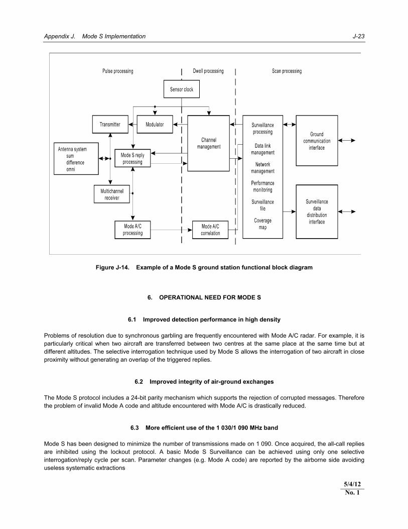
Appendix J. Mode S Implementation J-23
Figure J-14. Example of a Mode S ground station functional block diagram
6. OPERATIONAL NEED FOR MODE S
6.1 Improved detection performance in high density
Problems of resolution due to synchronous garbling are frequently encountered with Mode A/C radar. For example, it is particularly critical when two aircraft are transferred between two centres at the same place at the same time but at different altitudes. The selective interrogation technique used by Mode S allows the interrogation of two aircraft in close proximity without generating an overlap of the triggered replies.
6.2 Improved integrity of air-ground exchanges The Mode S protocol includes a 24-bit parity mechanism which supports the rejection of corrupted messages. Therefore the problem of invalid Mode A code and altitude encountered with Mode A/C is drastically reduced.
6.3 More efficient use of the 1 030/1 090 MHz band Mode S has been designed to minimize the number of transmissions made on 1 090. Once acquired, the all-call replies are inhibited using the lockout protocol. A basic Mode S Surveillance can be achieved using only one selective interrogation/reply cycle per scan. Parameter changes (e.g. Mode A code) are reported by the airborne side avoiding useless systematic extractions
5/4/12No. 1

J-24 Aeronautical Surveillance Manual
6.4 Shortage of Mode A code 6.4.1 In high traffic density areas and in areas with a complex organization of the air traffic services there are occasions when there are insufficient Mode A codes for assigning on the basis of a simple Mode A code allocation scheme. Mode S ELS provides the Aircraft Identification as an alternative means to identify all flights without recourse to the use of the Mode A codes. In this instance, those aircraft that are compliant with Mode S ELS may be assigned a common, rather than a unique, Mode A code. 6.4.2 The use of Mode S ELS is extending into areas with lower traffic densities because it is easier and more efficient to use Mode S ELS in a large block of airspace to reduce the number of flights transiting between areas where ELS is supported and those where it is not supported.
6.5 Reduced R/T use and improved safety 6.5.1 The Mode S format used for the encoding of the interrogations and the replies allows additional information (up to 112 bits in a message) to be exchanged between air and ground or between air and air. By supporting the extraction of a number of aircraft registers, the Mode S enables the Enhanced Surveillance application. 6.5.2 Due to the ready availability of key parameters available from EHS-compliant aircraft, an air traffic controller is presented with information rather than needing to contact the aircrew for the information. 6.5.3 The improved performance and ready availability of key information, such as the altitude the pilot has selected for the aircraft, have been seen to contribute to improved safety by reducing level bust occurrences. 6.5.4 The improved safety brought by the use of Mode S EHS may also be of interest in areas of lower traffic densities. As an increasing number of aircraft are becoming equipped to download certain parameters, it is expected to see the use of EHS spread in these areas, too.
7. MODE S IMPLEMENTATION CONSIDERATION 7.1 The operational use of Mode S provides better surveillance performance (e.g. better detection of aircraft and availability of additional aircraft information) which could, in certain operational scenarios, result in improved safety. However to achieve the expected benefits of Mode S, a thorough assessment should be conducted of the numerous technical, operational and legislative issues involved. An air navigation service provider contemplating the implementation of Mode S should therefore balance its needs for improved surveillance performance with its capacity to handle the considerable additional complexities. Upgrading from Mode A/C to Mode S should not be considered as a simple replacement exercise. Some of the associated issues or tasks to take into account are mentioned in the following paragraphs. 7.2 On conventional SSR type radar it was necessary to establish an appropriate Mode A/C interlaced interrogation pattern and the associated Pulse Repetition Frequency (PRF). On Mode S radar the configuration of the interrogation pattern (Mode Interlace pattern) (MIP) is more complex. A period of time shall be reserved for the Mode S all-call acquisition, another for the selective interrogations and yet another for Mode A/C only interrogation to detect the aircraft not yet Mode S-equipped. In general Mode S radar provides a fully configurable MIP which needs to be optimized, taking into account local constraints. 7.3 One of the constraints is the potential presence of faulty Mode S or Mode A/C transponders. This requires the addition of classical Mode A/C interrogations in the MIP to ensure their detection. This approach has been required in both the US and in Europe to support the operational introduction of Mode S. However this approach can obscure certain problems associated with faulty transponders and also contributes to 1 090 MHz RF pollution. This suboptimal
5/4/12 No. 1

Appendix J. Mode S Implementation J-25
interrogation scheme can be removed if an appropriate monitoring programme is established. The MIP of Mode S radar may need to be configured in order to cope with older Mode A/C-equipped aircraft, correct Mode S, incorrect Mode S and incorrect old Mode A/C transponders met in the coverage. 7.4 Mode S radars can be configured to provide different types of radar coverage like: a) surveillance coverage in which selective interrogations can be performed; b) lockout coverage where the aircraft will be locked out once acquired (i.e. where the aircraft does not
reply anymore to the all-call interrogations made using the specified interrogator code); and c) data link coverage where airborne data may be extracted. All aforementioned “coverages” should be configured differently depending on manufacturers and local/regional agreements. The correct configuration of the lockout coverage is critical as it directly impacts on the interoperability with the adjacent radars using the same interrogator code. The different coverage can be configured by a maximum range per sector or by using coverage maps defined in a global system of coordinates like the world geodetic system-1984 (WGS-84) system of coordinates. Radar coverage and especially the radar lockout coverage shall be carefully configured to ensure interoperability with the adjacent radars using the same interrogator code. This may force the implementing authority to think about the real operational requirement rather than just use the maximum available physical coverage. In general, high diligence is needed during planning and implementation of new Mode S radars to avoid compromising the performance of existing ones that operate in the same geographic area. 7.5 The “traditional” Mode A/C SSR transponder is a relatively simple avionic component providing two types of reply (Mode A code, Mode C code). The implementation of Mode S has drastically changed the level of complexity of SSR transponders used on board the aircraft. This is because Mode S requires: a) more complex functions which may have their own failure modes (e.g. the use of a phase demodulator
to decode the Mode S interrogations); b) more stringent requirements on the signal-in-space than on the Mode A/C transmissions (frequency
stability, pulse width, etc.); c) the management of a complex protocol with a significant degree of interdependency between the data
received and transmitted; and d) the transponder to act as a focal point of communication in relation with the rest of the avionics. The
number of interfaces involved makes the transponder more complex and dependent upon a correct installation on the aircraft (e.g. 24-bit aircraft address, ground switch and correct update rate on the input interfaces).
7.6 Mode S transponders may have been installed a long time ago to support the mandatory ACAS function. Their Mode A/C function has been permanently used by ATC but their Mode S functions may not have been used. Therefore should a failure impacting Mode A/C happen it would have been detected by ATC during normal operation and corrective action would have been undertaken. On the contrary, before implementing Mode S for ground surveillance, no system checked the correct operation of the Mode S transponders so a number of failures may have accumulated over the years of operation. 7.7 A number of Mode S transponder versions have been observed to be non-compliant with Annex 10 Volume IV, section 2.1.5.2 requirements (e.g. no SI code, no reply to aircraft register extraction although level 2, and incorrect all-call parity). Although actions have been taken in some areas (mainly where Mode S has been implemented) to address this problem, some aircraft with incorrect transponders still operate (mostly in areas where Mode S has not yet been implemented).
5/4/12No. 1

J-26 Aeronautical Surveillance Manual
7.8 During the initial deployment of European Mode S it was discovered that avionic upgrades performed on some aircraft had resulted in erroneous transponder operations so that, in some cases, the aircraft could not even be detected by the ground radar. It is therefore highly recommended that before commencing Mode S surveillance in a given airspace, a proper fleet monitoring programme be put in place for the purpose of timely detection and rectification of hidden transponder problems. 7.9 Remote Field Monitors (Parrots) may require an upgrade to ensure that they are compatible with Mode S ground stations. 7.10 A Mode S transponder can provide the barometric pressure altitude in 25-ft resolution if it is provided with such resolution by the pressure altitude sensor. Some aircraft are still equipped with Gilham encoders which have a 100-ft resolution only. Many existing ATM systems are based on the use of 100-ft resolution. In such cases, if pressure altitude is provided in 25-ft resolution, means should be provided to convert it to the 100-ft resolution as used by the ground ATM. The conversion is done by rounding the altitude to the nearest 100-ft altitude. The use of a 25-ft altitude barometric pressure altitude brings advantages for the ATM system in terms of early detection of vertical trajectory changes. However, experience has shown that it is necessary to modify the vertical trackers filter in a way to avoid false STCA alarms based on small altitude variations. 7.11 The communication lines for transferring surveillance information in a Mode S radar require much higher throughput as there is more information per aircraft. For example, compared to a Mode A/C radar, Mode S ELS and EHS require twice and three times more throughput, respectively. Also, a proper format (like ASTERIX Category 048) can be used to transmit the additional data to the centre. 7.12 Centralized trackers may need to be adapted to recognize the Mode S messages. The additional information present in Mode S data messages supports improved tracking algorithms. Any tracking systems deployed will need to be adapted to accommodate the Mode S data formats. Similarly further adaptations may be necessary to exploit the additional information contained within those messages which can enable improvements to the tracker functionality. Specifically, the multi-radar tracker should be modified to take into account the 24-bit aircraft address to facilitate the plot-to-track association. Additionally, if EHS is implemented, the centralized tracker should be upgraded to handle the additional aircraft parameters and to filter out possible spurious values. 7.13 The use of “Aircraft Identification” which is broadcast directly from the aircraft (in an implementation like the ELS), rather than via a ground-based correlation between flight plan and Mode A code, offers significant refinement in the surveillance infrastructure. In order to exploit such benefits and also to cope with the “common” or “conspicuity” Mode A codes, the Flight Plan Processing System (FPPS) may need to be modified accordingly. 7.14 Presenting the additional information broadcast by Mode S EHS-compliant aircraft to the controller can result in significant improvements in system safety whilst at the same time reducing controller workload (mainly by reducing radiotelephony). However, essential information only should be presented to ensure that the display remains legible and clear. 7.15 In geographical areas where there is an insufficient number of interrogator codes available, it may be beneficial to network a number of Mode S radars that have overlapping coverage in a cluster. This involves interconnecting Mode S radars by ground communications so that they can exchange position and 24-bit aircraft addresses. In that way, each interrogator does not have to rely on all-call interrogations to acquire every new aircraft entering the composite coverage area and can use selective interrogations for aircraft already “acquired” by the cluster. However, the implementation of a cluster requires additional functionality in the radars and proper ground communications. In addition some cluster designs may use an additional function known as a cluster controller to centrally manage the exchange of information with interrogators. Therefore, the additional costs, and the more complex means and method of management should be duly considered before a decision is made for cluster implementation.
5/4/12 No. 1

Appendix J. Mode S Implementation J-27
7.16 The replacement of an SSR Mode A/C with a Mode S which provides additional pieces of information is a major change to the ATM infrastructure. Therefore an appropriate review of possible implications with regard to safety and security should be undertaken in order to ensure that the introduction of the new systems has not degraded the existing configuration. A safety analysis would be highly desirable to ensure that the differences brought by Mode S are understood and that the partial or full failures of new equipment can be tolerated or mitigated. 7.17 Aircraft Identification (flight identification) configured in the aircraft avionics to identify flights may be used in place of the Mode A code for identification and correlation with the flight plan. In such environments, a non-unique Mode A code (conspicuity code) can be used for all aircraft that provide correct Aircraft Identification through their Mode S replies. Since Annex 6 contains no requirement for having an onboard means of configuring Aircraft Identification, appropriate regional or national regulations would be necessary to permit operational use of this feature in the desired airspace. It should be noted that Aircraft Identification is a new piece of information to enter and verify in the aircraft. The onboard setting of the Aircraft Identification can be incorrect or even forgotten by the flight crew. Moreover, in some aircraft, the crew may not have the means of entering or re-entering the Aircraft Identification. As such, before commencing the operational use of Aircraft Identification, flight crew should be properly trained, and necessary changes to operational procedures and controller workstations should be modified to indicate if the information correlates with the flight plan. Finally, a monitoring system to detect incorrect setting for the purpose of their rectification would be highly desirable. 7.18 Aircraft that are properly equipped for Mode S Enhanced Surveillance (EHS) provide, through replies to ground interrogations, the following additional information on their short-term intent: a) Magnetic Heading; b) Indicated Airspeed; c) Mach No.; d) Vertical Rate (barometric rate or, preferably, baro-inertial); e) Roll Angle; f) Track Angle Rate; g) True Track Angle; h) Ground Speed; i) Selected Altitude (MCP/FCU Selected altitude is currently used, FMS-selected altitude is not yet
available on all platforms); and j) Barometric Pressure Setting (where readily available). 7.19 One parameter that can be of considerable benefit to ATC is the MCP/FCU Selected Altitude. The receipt of this parameter by the ATC provides an additional confirmation that the vertical clearance has been well understood and followed. It can also provide for the early detection of possible level busts. Mode S EHS brings safety benefits even when only a portion of the traffic is properly equipped. Some aircraft can be configured to provide additional data items but their use should be considered with caution since some airborne installations may not have been certified hence data may be erroneous. Regulations are therefore needed to ensure correct airborne installations and the correctness of the data they transmit to the ground. Again, a proper fleet monitoring programme to validate the transmitted information would be highly desirable.
5/4/12No. 1

J-28 Aeronautical Surveillance Manual
7.20 It has been noted that from time to time the content of the extracted aircraft register does not correspond to the content of the requested register. For example, the content of Register 5016 is received when extracting Register 4016. This is due to interrogations transmitted by different radars arriving at the transponder at almost the same time. Only one reply is generated and received by the two radars resulting in one radar not receiving the content of the register it has requested. Different options can be implemented to decrease the impact of such phenomenon: limit the number of radar extracting aircraft registers; implement specific filters in radar or in the surveillance data processing to discard the erroneous data (e.g. when two different registers are received with the same content they are both discarded); implement Mode S protocol enhancement to differentiate the content of the MB field in DF20/21. 7.21 Mode S transponders are capable of downlinking ACAS Resolution Advisory (RA) reports the aircraft is experiencing. The operational use of ACAS RA is still being studied. Moreover, monitoring programmes have shown that some platforms are continuously transmitting empty RA reports. Such false RA reports should be filtered out before the information is provided to the ATC. More information can be found in Doc 9863. 7.22 Mode S radars continue to track the aircraft on the ground after landing. Although ICAO Annex 10 requires aircraft with an automatic weight-on-wheels type switch not to transmit all-call replies when on the ground, some aircraft with incorrect installations still continue to be acquired and tracked on the ground. These aircraft are shown on the ATC display resulting in useless clutter of labels around big airports. Systems implementing Mode S must have the possibility to filter out aircraft on the ground to avoid creating clutter on the controller display. Such filter can be located in the radar or in the control centre. The filter cannot rely only on the on-the-ground status provided by the aircraft and must use a combination of on-the-ground status, speed, and altitude information in limited geographical areas. 7.23 The normal Mode S acquisition process requires a number of successive steps to acquire, confirm the track, lock out the transponder and remove possible reflection(s). This process could take several scans. This is not a problem on the outer range of the radar coverage but it could be seen as a constraint after aircraft take-off. The constraint can be overcome by implementing specific zones in which the initialization will be done more rapidly. Zones of quick acquisition may need to be configured in proximity of runways in order to reduce the delay of acquisition after take-off. 7.24 The regulatory authority must ensure that appropriate legislation (e.g. in the form of an Aeronautical Information Publication) that mandates the carriage and operation of suitable avionics is published. Its date of publication should be such that aircraft operators have an acceptable period of time to undertake the necessary upgrade(s). Therefore, before deploying Mode S in an area, it must be ensured that legislative requirements pertaining to the operational introduction of Mode S are readily available, and the dates are consistent with the needs of the surveillance service provider. The regulation must detail the correct version of Mode S transponder required. 7.25 If the period of time allowed for the upgrades is significant, it may be necessary to implement some form of exemptions procedures to be applied during the transition period leading up to the operational introduction of Mode S. The time between the announcement of the Mode S carriage requirements and the date of full operational implementation is referred to as the transition period. It is necessary to ensure that, if a transition period is introduced, operational aspects and implications of mixed mode (i.e. both Modes A/C and S) operations are considered. As with all legislation, means of enforcing the requirements should also be put in place. 7.26 According to Annex 10, the aviation authority of each State is responsible for assigning 24-bit addresses to all aircraft in its registry using the block allocated by ICAO to that State. It has, however, been observed that in many cases the 24-bit aircraft address transmitted by the aircraft does not match its nationality (i.e. its State of Registry’s block). Care needs to be taken to ensure that the registration and the 24-bit address of every aircraft are processed and assigned simultaneously by the regulatory authority. 7.27 Interrogator codes (ICs) are a scarce resource. Before implementing Mode S radars it is necessary to coordinate the allocation of the required ICs with all the other civil and military users operating Mode S radars in the same area. In general this requires the establishment of a regional coordination process to allocate the ICs. The coordination between the civil aviation authorities is managed by the regional offices of ICAO, which may delegate that
5/4/12 No. 1

Appendix J. Mode S Implementation J-29
task to some other organizations (e.g. FAA and EUROCONTROL). If military authorities use Mode S in the same area, they must also be involved in the IC coordination process. Regional agreements should ideally be in place to facilitate the allocation of ICs. In areas where only a few Mode S radars are deployed, a simple paper process can be sufficient to ensure that there is no overlap between two radars using the same code. However where a large number of Mode S radars with overlapping coverage have been implemented (e.g. Europe and North America), a computerized tool for managing ICs would be helpful.
______________________
5/4/12No. 1


K-1
Appendix K
1 090 MHZ ES
Note 1.— The following description of 1 090 MHz ES is based primarily on the use of GNSS as the navigation source. While this is expected to be the principal source, the message formats for ES permit the reporting of position based on other sources of navigation (e.g. inertial navigation system). The message formats support the accuracy and integrity reporting of the position information. Note 2.— This appendix provides a high-level overview of the 1 090 MHz ES. More detail may be found in Doc 9871.
1. INTRODUCTION A technique that combines the capabilities of the SSR Mode S system with those of ADS-B is the 1 090 MHz ES (1 090 ES). This is accomplished by using an ES as the broadcast data link for transferring the aircraft-derived ADS report from the aircraft to airborne or ground users. In addition to airborne and ground surveillance, ES is expected to find application in enhancements to ACAS operation.
2. SYSTEM CONCEPT 2.1 Each operating Mode S transponder pseudo-randomly radiates (squitters) its unique Mode S address in an azimuth-omnidirectional pattern once per second. This acquisition (or short) squitter is a 56-bit transmission of 64-microsecond duration, broadcast on the Mode S transponder reply frequency (1 090 MHz). The acquisition squitter is used by ACAS to detect the presence of Mode S-equipped aircraft. In operation, an ACAS listens for acquisition squitters, extracts the 24-bit aircraft address contained in the squitter data and uses this address as the basis for discrete interrogation, as required, to perform surveillance on Mode S-equipped aircraft. This form of squitter has been in operational use with ACAS for many years. Its performance is well understood from the design and validation of ACAS as well as from the substantial experience with ACAS as an operational system. 2.2 The Mode S message protocol defines both 56-bit and 112-bit reply formats. The ES approach uses a 112-bit format. This creates a 56-bit message field for ADS-B data. All other fields remain the same as in the original acquisition squitter. 2.3 In operation, aircraft equipped with a GNSS receiver, or another navigation source, determine the position and velocity of the aircraft. This information is processed and formatted into the 56-bit ADS-B message fields of ES and broadcast by the Mode S transponder. The 56-bit acquisition squitter continues to be broadcast for compatibility with ACAS. The acquisition squitter transmission can be omitted in the future if all ACAS equipment is converted to receive and process the ES. 2.4 The omnidirectional pattern of an ES broadcast makes it possible to support both air-ground and air-air surveillance applications.

K-2 Aeronautical Surveillance Manual
2.5 In addition to the transponder implementation of ES described above, the system concept also includes the capability to transmit ES from a non-transponder device. The rationale for an ES/NT capability is to obtain a lower cost implementation of ADS-B for surface vehicles. An ES non-transponder device may also be used in connection with a Mode A/C transponder for general aviation purposes. The ES’s from a Mode S transponder are identified by a DF code equal to 17. ES/NT devices, however, use a DF code of 18 to be distinguished from Mode S transponders. The use of a different DF code format is used to ensure that replies from these ES/NT devices are clearly identified in order to prevent ACAS from attempting to interrogate them as part of ACAS hybrid surveillance. The ES/NT devices perform all of the ES functions of the transponder-based implementation, except those that directly depend on Mode S transponder functions. The ES concept is illustrated in Figure K-1.
Figure K-1. ES concept
ABC 123FL 280
XYZ 456FL 300
Surveillancedata
processor
AircraftreportsADS-B
GROUNDSTATION
ADS-Bmessage
Aircraft uses GNSSand/or inertial navigation
sensors to determineits position.
ATC display system
GNSS

Appendix K. 1 090 MHz ES K-3
3. OPTIONAL USE OF ACTIVE INTERROGATION ES ground stations may optionally include the capability of interrogation as well as reception. This capability could be useful for validation of ADS-B information.
4. SURVEILLANCE APPLICATIONS
4.1 Surveillance examples Examples of ADS-B surveillance applications that can be supported by ES are: a) air-ground: 1) en route; 2) approach/terminal; and 3) PRM; b) surface/aerodrome, 1) surveillance for runways and taxiways; 2) airport situational awareness; and 3) final approach and runway occupancy awareness; and c) air-air; 1) ACAS hybrid surveillance; 2) enhanced visual separation and approach; 3) in-trail procedure in oceanic airspace; and 4) conflict detection.
4.2 Air-ground surveillance 4.2.1 For approach/terminal operations, the squitter is received by approach ground stations. The antenna can be a single omni, providing a squitter reception range of 90 to 180 km (50 to 100 NM). 4.2.2 PRM surveillance can be supported using either the same antennas used for approach surveillance or dedicated antennas to provide the required coverage. 4.2.3 For en-route operation in higher density environments, a multi-sector antenna will likely be necessary. For example, a six sector high-gain antenna (with six independent low-noise receivers) can achieve a 370 km (200 NM) surveillance range. The multi-sector antenna may also be used in high traffic density areas to overcome interference effects and to limit the number of aircraft being processed by any single receiver. In lower density areas an omni-directional antenna may provide adequate performance.

K-4 Aeronautical Surveillance Manual
4.3 Surface surveillance Aircraft transmit squitters containing their positions even while operating on runways and taxiways. These squitters are received by several stations around the periphery of the airport. The number of ground receivers will be determined by airport layout and by squitter reception performance in the environment of the airport surface. Measurements have indicated that four or more stations may be needed to provide good coverage for most large airports.
4.4 Air-air surveillance
4.4.1 ACAS hybrid surveillance 4.4.1.1 Hybrid surveillance is a term used to describe ACAS use of passive ADS-B surveillance data for non-threat intruders. Use of passive surveillance in place of active interrogation results in reduced 1 090 MHz channel usage by ACAS. 4.4.1.2 If an ES is received at track initiation, an addressed interrogation is made to determine the aircraft range and altitude. This is compared to the relative range and reported altitude determined from a comparison of own and the intruder’s ADS-B information. If the ADS-B surveillance data are validated by ACAS active surveillance, the passive ADS-B surveillance data can be used as long as the intruder is not determined to be a near threat. 4.4.1.3 Monitoring after acquisition is based on an assessment of the imminence of a threat status of the intruder. If the intruder becomes a near threat in range or altitude, it is interrogated every 10 seconds. If the intruder becomes a near threat in both altitude and range, full active surveillance is performed every second. Full active interrogation and ACAS surveillance starts well before any TA or RA is issued.
4.4.2 Situational awareness enabled by CDTI CDTI enables situational awareness and is an option for aircraft that are equipped with a 1 090 MHz receiver. Such aircraft would listen to ES’s from nearby aircraft and display their positions and identity on a cockpit display. A range of 26 km (14 NM) can be supported for CDTI using a receiver equivalent to those in ACAS equipment. This range can be extended to over 93 km (50 NM) through the use of a low-noise receiver. Note.— For more information, see RTCA/DO-260A, Appendix E.
4.5 OTHER SURVEILLANCE APPLICATIONS ES can provide a low-cost means of surveillance for: a) small terminals that do not qualify for high-cost ground surveillance equipment; and b) en-route gap filling in mountainous or remote areas.

Appendix K. 1 090 MHz ES K-5
5. ES ADS-B MESSAGES
5.1 ES message types 5.1.1 ES makes use of five types of squitter: a) airborne position; b) airborne velocity; c) surface position; d) aircraft ID and emitter category; and e) event-driven. 5.1.2 The first four types of ES are regularly broadcast when the ES equipment is active and supplied with the required aircraft data. The even-driven squitter type is actually a communications mechanism to allow ADS-B applications to broadcast squitter data as needed to support these applications. 5.1.3 The initial version of ES messages were defined in RTCA DO-260. These are known as Version ZERO (0) formats. Complete definitions of message structures and data sources for the Version 0 formats are specified in Doc 9871, Appendix A. 5.1.4 The revised version of the ES messages are defined in RTCA DO-260A. These are known as Version ONE (1) formats. Complete definitions of data structure and data sources for the Version 1 formats are specified in Doc 9871, Appendix B. 5.1.5 Each ES transmission contains the aircraft address. This makes it possible to unambiguously associate the data in the various squitter formats with the originating aircraft. 5.1.6 Each ES transmission contains a 5-bit field which identifies a message “TYPE CODE” which is unique to each message. Version 0 formats allow airborne and surface position messages TYPE CODES to be associated with an NUC. Version 1 formats allow airborne and surface position messages TYPE CODES to be associated with an NIC. The NIC is reported so that surveillance applications may determine whether the reported geometric position has an acceptable level of integrity for the intended use. The NIC parameter specifies an integrity containment radius, RC. The SIL parameter acts in conjunction with the NIC parameter and specifies the probability of the true position lying outside that containment radius without alerting. 5.1.7 The airborne or the surface position squitter is transmitted depending on the aircraft’s VS. The aircraft ID and emitter category, and event driven squitters are transmitted as additional squitters in the air and on the ground. The 56-bit acquisition squitter is retained while airborne (and in certain cases when on the surface) for continued compatibility with current ACAS equipment. 5.1.8 The message data for each squitter format is obtained from a defined transponder register as indicated in Table K-1.
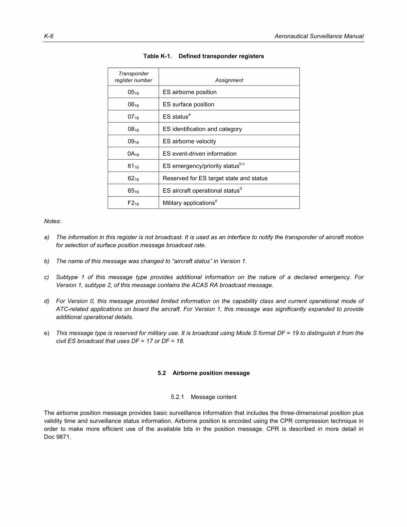
K-6 Aeronautical Surveillance Manual
Table K-1. Defined transponder registers
Transponder register number Assignment
0516 ES airborne position
0616 ES surface position
0716 ES statusa
0816 ES identification and category
0916 ES airborne velocity
0A16 ES event-driven information
6116 ES emergency/priority statusb,c
6216 Reserved for ES target state and status
6516 ES aircraft operational statusd
F216 Military applicationse
Notes: a) The information in this register is not broadcast. It is used as an interface to notify the transponder of aircraft motion
for selection of surface position message broadcast rate. b) The name of this message was changed to “aircraft status” in Version 1. c) Subtype 1 of this message type provides additional information on the nature of a declared emergency. For
Version 1, subtype 2, of this message contains the ACAS RA broadcast message. d) For Version 0, this message provided limited information on the capability class and current operational mode of
ATC-related applications on board the aircraft. For Version 1, this message was significantly expanded to provide additional operational details.
e) This message type is reserved for military use. It is broadcast using Mode S format DF = 19 to distinguish it from the
civil ES broadcast that uses DF = 17 or DF = 18.
5.2 Airborne position message
5.2.1 Message content The airborne position message provides basic surveillance information that includes the three-dimensional position plus validity time and surveillance status information. Airborne position is encoded using the CPR compression technique in order to make more efficient use of the available bits in the position message. CPR is described in more detail in Doc 9871.

Appendix K. 1 090 MHz ES K-7
5.2.2 Transponder insertion of barometric altitude 5.2.2.1 The barometric altitude is inserted into the airborne position message directly by the transponder, since this ensures that the altitude is based upon the same source as used for the altitude in a transponder reply. Provision has been made for the direct insertion of barometric altitude into the airborne position messages. Since provision is also made in the airborne position formats for future use of GNSS height data, the ATS subfield has been included in the ES status data register (transponder data Register 0716 ), to suppress the internal insertion of altitude when GNSS height is being used (Annex 10, Volume IV, Chapter 3, 3.1.2.8.6.8.2). It should be noted that the GNSS offset from barometric altitude is currently provided in the airborne velocity message. 5.2.2.2 The transponder insertion of altitude into the ES position message requires the use of a 12-bit altitude field. This allows the transponder to determine the quantization (25 or 100 ft) and results in a direct transfer of the AC field data (less the M-bit) into the airborne position message. 5.2.2.3 When the transponder determines that it is time to broadcast an airborne position squitter, it will (unless inhibited by the ATS subfield) insert the current value of the barometric altitude and surveillance status into the appropriate fields of transponder data Register 0516. The contents of this register will then be inserted into the ME field of DF = 17 and transmitted. Insertion in this manner ensures that: a) the squitter contains the latest altitude and surveillance status at the time of squitter transmission; and b) ground readout of Register 0516 will yield exactly the same information as contained in the previous
squitter.
5.2.3 Surveillance status subfield 5.2.3.1 In the acquisition squitter, the means to alert the ground of a surveillance or data link condition requiring ground interrogation is the setting of code 7 in the CA field. This indicates that one or more of the following conditions is set in the transponder: a) an air-initiated message or an ACAS RA is waiting; b) the SSR Mode A code has been changed (includes emergency); or c) there is an SPI condition. 5.2.3.2 This code is sufficient if ground stations are capable of interrogation. To provide similar information passively, the airborne position message contains a surveillance status subfield. The coding in this field indicates the presence of an emergency condition, a change in Mode A code or an SP.
5.3 Airborne velocity message The airborne velocity message contains velocity information and other aircraft state data. Together with the airborne position message, the information in the velocity ES provides a four-dimensional aircraft state vector providing additional information to improve the prediction performance of both airborne and ground-based tracking systems.

K-8 Aeronautical Surveillance Manual
5.4 Surface position message The surface position message provides the complete surface state vector in a single message. This is made possible since altitude and vertical rate reporting are not required on the surface. The use of a single squitter type on the surface is important. For the surface application, the majority of the channel activity will be ES’s. Therefore, use of a single squitter for aircraft state will lead to a higher surveillance capacity. Surface position is also encoded using the CPR compression technique in order to make more efficient use of the available bits in the position message. This is a higher resolution version of the technique used in the airborne position message.
5.5 Airborne/surface state determination 5.5.1 Selection of the surface format will normally be based on the use of a “weight on wheels” switch (also referred to as a squat switch). Override of the airborne position format is provided for certain classes of aircraft without a squat switch so that the surface format may be transmitted when on the ground. Provision is also made in the SD field of an addressed Mode S interrogation to command an aircraft to use the surface format. This command times out to prevent an aircraft from remaining in the surface format condition while airborne. Provision is also made in the SD field for a timed command to lock out surface squitters for cases where surface surveillance based on squitter transmissions is not required. 5.5.2 Aircraft with automatic means for determining the on-the-ground condition (squat switch) will use this input to determine whether to transmit the surface or the airborne squitter type. Aircraft that do not have a squat switch will report the airborne type, unless commanded by the ground to report the surface type. These commands may also be sent to aircraft with squat switches where they take precedence over the squat switch input. This provision is made to handle the case of a failed squat switch. 5.5.3 These commands can only affect the format type reported; they cannot change the aircraft determination of its on-the-ground condition. Thus, an aircraft without the means to set the on-the-ground condition will continue to report code 6 in the CA field, and an aircraft, that senses an airborne status, with the means to set the on-the-ground condition, will continue to set code 5, independent of the ES format that is emitted. 5.5.4 When an aircraft takes off, the squat switch input or commands from the ground station will cause a change back to the airborne format. Commands to report the surface position type will timeout to prevent continued transmission of the surface format to cover the case of loss of contact with the aircraft after take-off.
5.6 Aircraft ID and category message The identification and category squitter provides the aircraft type category, as well as the aircraft ID corresponding to item 7 of the ICAO flight plan. Such information is useful for visual acquisition and for wake vortex avoidance and is necessary for operational identification of the aircraft. (See Annex 10, Volume IV, Chapter 3, Table 3-8, Character coding for transmission of aircraft ID by data link.)
5.7 Event-driven message 5.7.1 The event-driven squitter is a message transfer protocol intended for the transmission of additional information that may be needed infrequently. It may also be associated with an airborne application that may not be used by all aircraft. This message type is also defined as a means for accommodating the needs of future ADS-B applications. 5.7.2 The ES aircraft status message is used to provide information about a change in the aircraft status, such as the emergency/priority indicators.

Appendix K. 1 090 MHz ES K-9
5.7.3 The ES aircraft operational status message (for Version 1 formats only) is used to provide the current status of the aircraft. Among other aircraft parameters, the operational status message contains the version number of the ADS-B transmitting equipment, the SIL parameter and the navigation accuracy category for position (NACP). The NACP parameter is reported so that surveillance applications may determine whether the reported geometric position has an acceptable level of accuracy for the intended use.
6. ES PROTOCOLS
6.1 Channel access 6.1.1 ES’s are broadcast using a pseudo-random channel access technique. This is the same technique that is used for the acquisition squitter that is in operational use in support of ACAS. A pseudo-random technique for ES provides some advantages which are explained in 6.1.2 and 6.1.3 below. 6.1.2 For a high data rate system (like Mode S) it provides higher capacity than other channel access techniques. For example, if a TDMA approach were used on 1 090 MHz supporting surveillance to 460 km (250 NM), this would require a 1.5 milliseconds guard time following each 120 microseconds ES. This would lead to a maximum capacity of approximately 600 aircraft using the 1-second update required to support ACAS. 6.1.3 The pseudo-random approach has the ability to satisfy aviation surveillance users with different update requirements. The ACAS surveillance requirement is for a 1-second update rate out to about 26 km (14 NM). A 5- to 9-second update is required for terminal ATC operation for aircraft out to about 110 km (60 NM). En-route interrogators currently provide up to a 12-second update rate to a range of 370 km (200 NM). An ACAS receiving ES would operate at a sensitivity level adequate for 26 km (14 NM). This level means that the ACAS squitter receiver would process squitters from a small fraction of the aircraft visible to a terminal or en-route squitter receiver, permitting the ACAS to operate at a squitter reception level suitable for a 1-second update. The en-route and terminal receivers operate with a much higher signal traffic density because of their greater operating range. While leading to a lower probability of reception of a single squitter, the multiple squitter opportunities produce a high probability of an update during a 5- to 12-second update period. Both requirements are handled simultaneously by the same pseudo-random squitter.
6.2 Antenna selection For aircraft with antennas, diversity squitters are transmitted alternately from top and bottom antennas when the aircraft is airborne. When the aircraft is on the surface, the default is to use the top antenna only. The alternative is to alternate between the top and bottom antenna using commands in the SAS subfield of the SD field for DI = 2 that is delivered via an addressed uplink interrogation.
6.3 Reporting of ES capability Provision has been made in the data link CA field to identify a transponder with ES capability (bit 34 of transponder data Register 1016). This is desirable to monitor transponder equipage via narrow-beam Mode S interrogators, since they cannot receive ES broadcasts.
6.4 Timeout of transponder data registers 6.4.1 Three of the transponder data registers used for regularly scheduled ES’s with frequently changing data content (airborne position, airborne velocity, surface position) are cleared if they are not updated within 2 seconds,

K-10 Aeronautical Surveillance Manual
except for the altitude and surveillance status in the airborne position message. This is done to prevent the transmission of outdated information. This timeout is not required for the event-driven squitter since it is loaded each time that an event-driven squitter is to be transmitted. 6.4.2 The internal insertion of data by the transponder into these registers (e.g. altitude and surveillance status fields for the airborne position report) does not qualify as a register update for the purposes of this timeout condition.
6.5 Suppression of unnecessary ES’s 6.5.1 Provision has been made to emit acquisition squitters upon the power up of the transponder. ES operation will only be initiated if a message is loaded into transponder data Registers 0516 (airborne position), 0616 (surface position), 0916 (airborne velocity) or 0816 (aircraft ID and category). 6.5.2 Once a decision is made to broadcast a specific type of ES, this squitter type will continue to be broadcast for 60 seconds if inputs to its related transponder data register stop being updated. After timeout, this squitter type may contain an ME field of ALL ZEROs. Continued transmission is required so that receiving devices know that the data source for the message has been lost. If the squitter transmission was stopped, receiving devices could conclude that the aircraft was no longer within reception range.
6.6 Future suppression of acquisition squitter 6.6.1 Airborne aircraft generating ES’s must continue to transmit acquisition squitters in order to remain compatible with the current ACAS equipment. If all ACAS equipment were converted to receive the ES (as a minimum to read the 24-bit address and the CA field), the acquisition squitter would no longer be required. Channel occupancy would be reduced if the acquisition squitter could be suppressed. 6.6.2 Acquisition squitter will continue to be broadcast by transponders that are not emitting any ES’s. This is necessary in order to ensure acquisition by ACAS. Thus, ACAS will need to retain the ability to receive the acquisition squitter even after the implementation of the ability to receive the ES.
6.7 ES transmission rates
6.7.1 Transmission rate overview 6.7.1.1 The airborne position and velocity squitters are each transmitted pseudo-randomly twice per second when the aircraft is airborne. When airborne, the identification and category squitter is transmitted pseudo-randomly once every 5 seconds. On the surface, the surface position squitter is transmitted pseudo-randomly twice per second when the aircraft is moving and once per 5 seconds when the aircraft is stationary. On the surface, the identification and category squitter is transmitted pseudo-randomly once per 5 seconds when the aircraft is moving and once per 10 seconds when the aircraft is stationary. A determination of aircraft motion is made outside of the transponder based on monitoring the position and velocity data. The result of this determination is passed to the transponder via transponder Register 0716. 6.7.1.2 A squitter may be delayed, but not omitted, if the transponder is busy with an addressed transaction or another squitter. A delayed squitter will be transmitted at the next available opportunity.

Appendix K. 1 090 MHz ES K-11
6.7.2 Airborne position and velocity squitter rate considerations ES operates on a channel that is shared with other users. In the airborne case, the majority of the activity is because of conventional SSR or ACAS replies. The rate of successful ES receptions will be influenced by the transmission rate of the transponder. This rate must be at least once per second in order to support the update rate required by ACAS. Since most of the channel activity is background interference, an average rate of two per second for the airborne position and velocity squitters is used to obtain a higher operating capacity.
6.7.3 Identification and category squitter rate considerations This squitter contains static data (aircraft ID and category). For this reason, it can be transmitted at a lower rate than the position and velocity squitters. Since acquisition of an aircraft may not be considered complete until the identity is received, a squitter rate must be chosen that will not cause a long delay in the reception of identity. A transmission rate of once per 5 seconds has been selected for this purpose.
6.7.4 Surface position squitter rate considerations 6.7.4.1 Variable transmission rates. The required surface position update rate is once per second. Since surface multi-path will result in loss of some squitters, a higher than once per second data rate is required. For this reason, the same twice per second transmission rate is used. 6.7.4.1.1 On the surface, the majority of the channel activity results from squitter transmissions due to the following: a) transponders do not respond to conventional SSR or Mode S all-call interrogations while on the
surface; and b) surface squitter receiving stations operate with a very short range. They therefore receive replies from
only those aircraft operating near the airport. 6.7.4.1.2 For this reason, it is desirable to lower the squitter rate for stationary traffic as a means of increasing surface capacity. The approach used to reduce the squitter rate for surface aircraft is as follows: a) when the aircraft is moving, it emits: 1) position squitter twice per second; and 2) identity squitter once per 5 seconds; b) when the aircraft is stationary, it emits: 1) position squitter once per 5 seconds; and 2) identity squitter once per 10 seconds; c) transition to the higher squitter rate occurs when motion is detected on board the aircraft; and d) the content of the SD field of an addressed interrogation is used to prevent a transition to the low rate
when the aircraft is in a critical position (e.g. stopped at the entrance to an active runway).

K-12 Aeronautical Surveillance Manual
6.7.4.2 Reporting of variable surface squitter rate capability. As indicated earlier, the variable surface squitter rate will be determined outside of the transponder based on position and velocity information. For example, this function may exist in the navigation unit or in the Mode S ADLP. A means is needed to pass this information to the transponder and to notify the ground that this transponder is capable of determining its surface squitter rate. Transponder Register 0716 is defined for this purpose. The airborne process that determines the rate will set the contents of squitter TRS. The TRS information will be read by the transponder to set the surface squitter rate. In addition, the TRS contents can be read by the ground to determine whether the aircraft is capable of surface squitter rate determination, or whether the rate must be controlled by the ground. 6.7.4.3 Surface squitter lockout. Some airports may not need to use the surface position squitters transmitted by surface aircraft. 6.7.4.3.1 For this reason, a command has been provided in the SD field for DI = 2 of an addressed interrogation to suppress surface position squitters for 60 seconds in order to reduce channel occupancy at these airports. 6.7.4.3.2 This command has no effect on a transponder that is broadcasting the airborne type of ES. Therefore, aircraft without the means of determining the on-the-ground condition must first be commanded to transmit the surface format before they can be placed into a state of squitter lockout. Both of these commands have a specific timeout period. 6.7.4.3.3 Acquisition squitters will continue to be broadcast during a period of surface squitter lockout.
6.7.5 Event-driven squitter rate considerations The actual rate and duration of the event-driven squitter will be determined by an application that is generating the messages that are input into the transponder ES event-driven information Register 0A16. The transponder will broadcast each message that is input into the event-driven register a single time. A maximum rate of no more than twice per second will be permitted by the transponder.
7. INDEPENDENCE OF NAVIGATION AND SURVEILLANCE
7.1 Potential for loss of independence 7.1.1 Traditionally, ATC has required the use of separate and independent systems for CNS. Such independence of functions makes it unlikely that an aircraft could lose more than one of its capabilities at the same time. It also provides a robust backup in the event of a failure of one of the systems. For example, loss of navigation capability on board an aircraft can be accommodated through the use of ground vectors provided by an air traffic controller based on ground SSR interrogation data. 7.1.2 If used as the sole means of surveillance, ADS-B inherently combines the aircraft navigation and surveillance capabilities. As a consequence, loss of navigation capacity would not be able to be accommodated by ADS-B alone, since ATC would lose surveillance and, therefore, would be unable to provide vectors. 7.1.3 Moreover, an undetected failure of the navigation system that resulted, for example, in a slowly increasing error may not be detected. This can happen since both pilot and ground controller would see the aircraft on its intended course, when, in fact, the aircraft could be on a very different course. 7.1.4 As such, the use of ADS-B as a primary means of surveillance should be carefully considered, particularly if it is planned as a direct replacement for SSR.

Appendix K. 1 090 MHz ES K-13
7.2 Validation of ADS-B reports 7.2.1 The integration of ES into the SSR Mode S system offers a straightforward way to obtain the benefits of ADS-B while still maintaining independence of CNS. This is based on the use of active interrogation to validate ES surveillance. 7.2.2 The technique can be applied to both the ground ATC and ACAS surveillance applications. The active surveillance is used to validate the ADS-B reported surveillance, and to replace it if an aircraft loses its navigation capability. 7.2.3 If the validity check at track initiation is successful, the aircraft can be maintained on ADS-B and periodically monitored to verify continued correct operation of the navigation system. If a check fails at any time, then the track can be maintained by active surveillance. 7.2.4 Another method for validating ADS-B data is to deploy ADS-B with MLATs. This option has the advantage of maximizing the use of ground infrastructure since multilateration receivers include the capability to receive and decode ADS-B messages. Such an option has the advantage of being completely passive.
8. ES PERFORMANCE Information on ES performance is provided in RTCA/DO-260A. Appendix E of that document specifies the transmitter and receiver requirements for air-air range, and Appendix P provides the results of simulations that were conducted to estimate ES performance in high and low traffic and in interference environments.
______________________


L-1
Appendix L
MLAT
1. INTRODUCTION 1.1 Multilateration is a form of cooperative and independent surveillance system that makes use of signals transmitted by an aircraft (normally the 1 090 MHz SSR transponder replies or squitters) to calculate the aircraft’s position. Since MLATs can make use of currently existing aircraft transmissions, they can be deployed without any changes to the airborne infrastructure. 1.2 For the processing of the signals on the ground, appropriate receiver stations and a central processing station are required. 1.3 Multilateration techniques have been successfully deployed for airport surveillance for quite some time. Presently, these same techniques are used for larger areas such as en-route or approach areas and are called WAM systems.
2. PRINCIPLE OF OPERATION 2.1 An MLAT consists of a number of antennas receiving a signal from an aircraft and a central processing unit calculating the aircraft’s position from the TDOA of the signal at the different antennas. 2.2 The TDOA between two antennas corresponds, mathematically speaking, with a hyperboloid (in 3-D) on which the aircraft is located. When four antennas detect the aircraft’s signal, it is possible to estimate the 3-D position of the aircraft by calculating the intersection of the resulting hyperbolas. 2.3 When only three antennas are available, a 3-D position cannot be estimated directly, but if the target altitude is known from another source (e.g. from Mode C or when the aircraft is on surface) then the target position can be calculated. This is usually referred to as a 2-D solution. It should be noted that the use of barometric altitude (Mode C) can lead to a less accurate position estimate of the target, since barometric altitude can differ significantly from geometric height. 2.4 With more than four antennas, the extra information can be used to either verify the correctness of the other measurements or to calculate an average position from all measurements, which should have an overall smaller error. The example in Figure L-1 should clarify the principle. It shows a WAM system consisting of five receiver stations (numbered 0 to 4). 2.5 Assuming that the aircraft’s signal is detected at all sites, the first three diagrams in Figure L-2 show the hyperboloids corresponding to the TDOA of the signal at sites 0 and 2, 0 and 3, and 0 and 4, respectively. The central processing station calculates the intersection of all the hyperboloids as shown in the last diagram. 2.6 There may be more than one solution to the multilateration calculation as the hyperboloids may intersect in two places. Typically the correct solution is easily identified.

L-2 Aeronautical Surveillance Manual
Figure L-1. Five-receiver stations layout
12
3 4
0
0–10–20–30–30
–20
–10
10 20 30
10
20
30
Aircraft
X/NM
Y/N
M
0

Appendix L. MLAT L-3
2.7 The geometry of the system has, in general, a large impact on the accuracy that can be obtained. As long as the aircraft is inside the enclosing 2-D area of the ground antennas, the calculated position will have the highest accuracy; outside this area, the accuracy will degrade quickly. 2.8 A distinction can be made between active and passive MLATs. A passive system consists only of receivers, whereas an active system has one or more transmitting antennas in order to interrogate the aircraft’s SSR transponder. The main advantage of an active system lies in the fact that it is not dependent on other sources to trigger a transmission from an aircraft. The main disadvantage is that it generates additional interference on the 1 030 MHz and 1 090 MHz channels.
Figure L-2. Intersecting hyperboloids

L-4 Aeronautical Surveillance Manual
3. SYSTEM ARCHITECTURES
3.1 Calculation of TDOA 3.1.1 WAM systems can be categorized by two different criteria. First, they can be divided by the method that is used to calculate the TDOA of the signal, and second, they can be categorized by the method, if any, used to synchronize the receivers. 3.1.2 The most common method used to calculate the TDOA of 1 090 MHz signals is to measure the TOA at each individual receiver and then to calculate the difference between them, as shown in Figure L-3. Other methods are not described in this document.
Figure L-3. TOA data flow
Other TOAmeasurements
TOAmeasurement
TOAmeasurement
DigitizedwaveformBaseband
Down converter Digitization
PositionData
Tracker optional or may beincluded in other equipment
Track data
TDOA algorithm TOA correlation
Timedifferences
Tracker

Appendix L. MLAT L-5
3.2 Synchronization methods 3.2.1 Synchronization of time is fundamental to MLATs. In order to calculate the position, it is necessary to know the time difference from a signal arriving at one antenna in the system to the arrival of the signal at another antenna in the system. This is commonly termed the TDOA. However, the signal is time-stamped during the digitization process, which is delayed in time relative to the TOA at the antenna by the group delay of the down-conversion process. 3.2.2 Therefore, to accurately calculate the TDOA, this delay must be exactly known and taken into account. Additionally, the digitization process for each receiver chain must be referenced to a common time base, otherwise the signals at the various sites will be referenced to differing clocks and not directly comparable. Figure L-4 shows the group delay and synchronization components. Synchronization is defined as the method by which the digitization processes of the signals to each site are tied together.
Figure L-4. Group delay and synchronization
Down converter
Down converter
Digitization
Digitization
Baseband
Baseband
Group delay
Synchronization
Digitizedwaveform
Digitizedwaveform

L-6 Aeronautical Surveillance Manual
3.2.3 Figure L-5 shows the topology of the various synchronization technologies in use on WAM systems. These technologies are described in more detail in sections 3.3 to 3.8.
3.3 Common clock systems 3.3.1 Common clock systems use simple receivers with most of the complexity at the central processing site. Common clock systems receive the RF signals from the aircraft and down convert to an IF. This IF signal is transmitted from each receiver to a central site over a custom analogue link. Conversion to baseband or video and subsequent digitization is then carried out at the central site with reference to a common clock for each receiver.
Figure L-5. WAM synchronization topology
Common clocksystems
Distributed clocksystems
WAM systems
Transpondersynchronized
systems
GNSSsynchronized
systems
Stand-aloneGNSS
synchronization
Common viewGNSS
synchronization

Appendix L. MLAT L-7
3.3.2 With this architecture, there is no need to synchronize each of the outlying receivers with each other as digitization occurs at the central site. However, the group delay between signal reception at the antenna and digitization at the central site is large, as it includes the delays of the custom analog link which must be accurately known for each receiver. This means both the receive chain and the data link must be rigorously calibrated to measure group delay. As the delay in the link increases, often due to an increased link distance or system baseline, achieving a given accuracy will become more difficult as delays will vary as a fraction of the total path. 3.3.3 This architecture benefits from a simple receiver with low power consumption and most of the complexity in the central multilateration processor. However, the signal delay between the antenna and the multilateration processor puts stringent requirements on the type and range of the link. Typically a single hop custom microwave link is used or dedicated fiber is laid between the sites as illustrated in Figure L-6. The location of the multilateration processor must typically be at the centre of the system to minimize communication link distances.
Figure L-6. Common clock architecture
Down converter
Down converterAnalogue IF link
Analogue IF link
Analogue IF link Digitization
Commonclock
DigitizationCorrelation,TDOA and
tracking
Digitization
Down converter

L-8 Aeronautical Surveillance Manual
3.4 Distributed clock systems Distributed clock systems use more complex receivers to reduce the demands on the data link (see Figure L-7). The RF signal is down-converted to a baseband or video signal and then the digitization, code extraction and TOA measurement are all done at the receiver. This gives great flexibility in the data link as just the SSR code value and the TOA need to be transmitted to the processing site from each receiver. Any digital data link can be used, and the link latency is not critical. However, a mechanism must be used to synchronize the clocks at the local sites. This is the most common approach used in WAM systems.
Figure L-7. Distributed clock architecture
Down converterDigitization and
TOAmeasurement
Baseband
Localclock
Down converterDigitization and
TOAmeasurement
Correlation,TDOA and
tracking
Baseband
Localclock
Down converterDigitization and
TOAmeasurement
Baseband
Localclock
Digital link
Digital link
Digita
l link

Appendix L. MLAT L-9
3.5 Transponder synchronized systems 3.5.1 Transponder synchronized systems use transmissions from a reference transponder to tie up the clocks at each of the receiver sites (see Figure L-8). The reference timing signal and the aircraft’s SSR transmission pass through the same analog receive chain, which means that common delays cancel out the delay bias caused by the analogue components, allowing an accurate system to be produced for short baselines. At longer baselines atmospheric delays have an impact that reduces accuracy. The synchronization transponder does not need to be collocated with the central multilateration processor, but it does need to have line of sight to each of the receivers. For a WAM system this means that tall masts or towers will typically be needed even in flat regions. 3.5.2 It is possible to use multiple synchronization transponders on an extended system, provided every pair of receivers can be linked to every other pair by means of common references.
Figure L-8. Transponder synchronized architecture
Down converterDigitization and
TOAmeasurement
Baseband
Localclock
Down converterDigitization and
TOAmeasurement
Correlation,TDOA and
tracking
Baseband
Localclock
Down converterDigitization and
TOAmeasurement
Baseband
Referencetransponder Local
clock
Referenceclock
Digital link
Digital l ink
Digital
link

L-10 Aeronautical Surveillance Manual
3.6 Stand-alone GNSS synchronized system An external common timing reference such as GNSS can be used to provide a common timing reference for each of the receivers. The timing of the GNSS system is maintained very accurately so it can be used as a common reference for the receivers. For MLATs it is only the time difference between receiver sites that is of interest, not the absolute time. It is therefore possible to synchronize the receivers of an MLAT to within 10–20 nanoseconds by using a GPS disciplined oscillator at each site. GNSS synchronized systems are much easier to site than common clock and transponder systems as they do not need tall towers for synchronization and any digital data link can be used. Integrity checking of the GNSS timing relies on the integrity of the GNSS receiver, so selection of a suitable receiver with receiver autonomous integrity monitoring capabilities is essential. The architecture is illustrated in Figure L-9.
3.7 Common-view GNSS synchronized system For situations where the stand-alone GNSS synchronization between receivers is not accurate enough, a common view synchronization method can be used. Common-view systems use GNSS satellites that are in view of all the receivers (see Figure L-10). This allows a large number of the error source to be removed as they are common between signals, and thus provides a significantly more accurate synchronization solution. Subnanosecond accuracies can also be achieved using this technique.
3.8 Synchronization summary The characteristics of the various synchronization schemes with respect to their application to WAM are summarized in Table L-1. It should be emphasized that this is an attempt to summarize the fundamentals of each architecture over long baselines and not to comment on specific deployments.
3.9 Passive and active systems MLATs can be either passive or active. Passive systems rely on the transmissions from an aircraft’s transponder that are solicited by other equipment and on unsolicited squitter responses. Active systems can solicit their own response from aircraft in addition to any detected passively. The systems are described in 3.9.1 to 3.9.3 below.
Table L-1. WAM synchronization methods
Accuracy Baseline Link
choice Mast Line of Sight
Common clock Medium Medium Microwave Fiber
High Low
Yes No
Transponder synchronization Medium Medium Any High Yes
Standard GNSS Low Any Any Low No
Common-view GNSS High Large Any Low No

Appendix L. MLAT L-11
Figure L-9. GNSS synchronized architecture
Correlation,TDOA and
tracking
Digital link
Digital link
GNSS constellation

L-12 Aeronautical Surveillance Manual
Figure L-10. Common-view GNSS synchronized architecture
Correlation,TDOA and
tracking
Common viewprocessing
Digita
l link
Digital link
GNSS constellation

Appendix L. MLAT L-13
3.9.1 Passive MLATs 3.9.1.1 Passive MLATs do not interrogate the aircraft transponder; this offers two advantages in terms of spectrum usage. First, no transmission licence is required for the installation and use of the system. Second, there is no increase in the number of 1 030 MHz interrogations or 1 090 MHz replies caused by the system. 3.9.1.2 In general, passive MLATs will acquire aircraft within range of the system if one or more of the following is true: a) the aircraft is equipped with a Mode S transponder; b) the aircraft is equipped with a Mode A/C transponder and within range of one or more ground
interrogators; and c) the aircraft is equipped with a Mode A/C transponder and within range of one or more ACAS-equipped
aircraft. 3.9.1.3 This means that, in general, passive MLATs are best suited to: a) busy areas with a high volume of ACAS-equipped traffic; b) areas with existing MSSR surveillance infrastructure; c) areas where Mode S use is mandatory; and d) areas where ES ADS-B is mandatory. 3.9.1.4 In general, passive MLATs may not perform as well with Mode A/C only aircraft at low altitude as there will be fewer Mode A/C interrogators to illuminate the aircraft since they may be below coverage of ground interrogators. 3.9.1.5 It should also be noted that while it is technically feasible to track aircraft based on Mode S acquisition squitters only, this does not provide enough information for current operational requirements. Currently, both the aircraft ID and pressure altitude are required by controllers. This information is not available in the Mode S acquisition squitter but is provided in the Mode S ES.
3.9.2 Active WAM systems 3.9.2.1 Active MLATs perform all the same functions as passive systems, and in addition, they can solicit their own replies from aircraft. The antenna for an active MLAT is much simpler than for an MSSR interrogator. A rotating antenna needed for the SSR is not required; instead, either an omnidirectional or sectored antenna may be used. 3.9.2.2 One scenario that may require the use of an active MLAT is for terminal area surveillance. Passive techniques can be used to acquire surrounding aircraft that are within the range of existing MSSR systems. A short-range interrogator can be used to acquire low-level aircraft on approach that fall below the coverage of existing MSSR systems. 3.9.2.3 In a Mode S environment, aircraft can be acquired by the MLAT from squitter transmissions. For the terminal area application, aircraft on approach could benefit from a higher update rate as this improves accuracy and probability of detection. Therefore, individual aircraft can be selectively interrogated more frequently. 3.9.2.4 Active MLATs can also be used to acquire specific data from properly equipped aircraft just like Mode S radars. The Mode S acquisition squitter can be used to acquire the aircraft passively by Mode S address, and surveillance interrogations can be used to obtain additional data such as the Mode A code, aircraft ID (e.g. call sign) and pressure altitude.

L-14 Aeronautical Surveillance Manual
3.9.2.5 In the terminal area consideration must be given to aircraft on the ground potentially responding to all call interrogations. It may be possible to site the active antenna so that it does not illuminate the taxiways or apron. Directional antennas are another method of excluding certain areas. 3.9.2.6 The use of selectively addressed surveillance interrogations will reduce unwanted replies. If this is used in conjunction with a sectored antenna, it will be possible to limit uplink requests to a particular sector. 3.9.2.7 Active MLATs can also be used to calculate the range to the target in the same way that MSSR and ACAS systems do. This information may supplement the position calculated using TDOA. In addition, it is used to improve the position accuracy outside the multilateration footprint.
3.9.3 Passive/active WAM systems 3.9.3.1 Active WAM systems provide benefits but at the expense of potentially significant interference when multiple WAM systems are deployed in high density environments. The use of omnidirectional antennas to solicit Mode S replies causes significant interference because all Mode S aircraft in signal range are occupied for 35 microseconds for each interrogation, since they must decode the interrogation to determine whether the interrogation contains their address. 3.9.3.2 All WAM systems with active capability must be designed to use active transmissions only when there is no passive data available. For example, the Mode S ES ADS-B technique will passively provide sufficient transmissions for multilateration and all of the normally required operational information (e.g. aircraft ID and pressure altitude). Except for accuracy improvement there should never be a need to actively interrogate a Mode S aircraft equipped with a normally functioning 1 090 MHz ES capability (see 3.9.2.7 of this appendix).
4. IDENTIFICATION AND ALTITUDE DETERMINATION OF AIRCRAFT 4.1 There is a difference between the requirements for technical identification and the current requirements for operational identification. Technically the Mode S address is adequate information to accurately associate new plots with a track. This means that the Mode S acquisition squitter provides the basis for an MLAT to detect, and track an aircraft including measuring its geometric height. 4.2 On the other hand, operationally the controller needs to know the aircraft ID (e.g. call sign) and pressure altitude of the aircraft. This means that an active capability may be required for operational rather than technical reasons. Active transmissions will not be needed for Mode S aircraft equipped with 1 090 MHz ES, since aircraft ID is provided passively.
5. TECHNICAL CONSIDERATIONS
5.1 Receiver characteristics
5.1.1 Sensitivity Sensitivity is commonly defined as the minimum power signal that the system can detect. As the power of any signal drops with the square of the distance (one-way) clearly the sensitivity will dictate the range of the MLAT. Additionally, as TOA accuracy is a function of signal to noise ratio (SNR) which is affected by sensitivity, the accuracy of the system will also be affected.

Appendix L. MLAT L-15
5.1.2 Dynamic range The dynamic range dictates what range of power levels may be detected simultaneously by a receiver. Ideally a receiver must have sufficient dynamic range to detect aircraft at the minimum and maximum required range simultaneously. If this is not possible, lower signals may be lost (even when the power is above the sensitivity level) or a receiver may be sent into compression distorting the output signal. Therefore, dynamic range and sensitivity must be considered jointly when predicting a receiver’s coverage.
5.1.3 Clock rate Fundamentally, the faster the clock rate, the higher the accuracy of the TOA or TDOA measurement.
5.1.4 Delay The delay of the signal between antenna and digitization must be known. This delay is far greater for common clock systems than for distributed clock systems as the digitization occurs after the signal has been transmitted to the central site. It may be assumed that group delay will be measured and calibrated during system commissioning activities for any MLAT. Therefore, the main area of concern is how accurate this calibration is and how the delay will vary in use. To this end, the system should be designed to ensure that delay changes are either calibrated or known with variation of received power level and frequency, and environmental effects such as aging or temperature related variations.
5.1.5 Antennas 5.1.5.1 Antenna choice. The choice of antenna, both for SSR 1 090 MHz signals and GNSS, if required, is critical and is briefly discussed in 5.1.5.2 and 5.1.5.3 below. 5.1.5.2 Antenna for SSR signals. The antenna used for SSR signals has three critical parameters: a) Peak gain, which together with the receiver sensitivity, dictates the system coverage; b) Gain/beam pattern, which should be suitable for limiting multipath while ensuring uniform coverage
against elevation angle. If required, non-omnidirectional antennas may be used to increase range in a given direction; and
c) Bandwidth, which is important for limiting out of band noise and improving system performance. 5.1.5.3 Antenna for GNSS signals. If a system utilizes GNSS synchronization, it is important that an appropriate antenna be chosen to minimize the effect of multipath and interference. Various other RF components are also required to reduce internal reflection and thus improve the VSWR.
5.2 Signal corruption 5.2.1 The transponder signal received by the system may be subject to corruption, which can be caused by a combination of multipath, garble and interference. 5.2.2 Multipath can cause multiple copies of the same signal to be received due to reflections from objects such as the ground, water, buildings or other aircraft. Antenna choice can help to reduce multipath.

L-16 Aeronautical Surveillance Manual
5.2.3 Short path differences cause the same reply to arrive at multiple times with the pulses overlapping. Typically, the direct and earliest path will be at a higher level than at the reflected paths. These overlapping but attenuated pulses cause the pulse shape of the direct received signal to deform and can have a serious impact on TOA accuracy. 5.2.4 Long path differences result in multiple copies of the same reply to be received. If this is undetected, it can cause ghost tracks. 5.2.5 Garble occurs when two or more different signals are received that overlap in time. The probability of garble occurring on any given signal increases with the density of the SSR signal environment. 5.2.6 Both multipath and garble have an impact on the accuracy of multilateration receivers and affecting probability of detection as well. In many cases, especially with multipath, the signal itself can be recovered sufficiently for identification purposes. However, the deformation of the signal affects the accuracy of any TOA measurement or cross-correlation. Accuracy can be maintained by rejecting these signals, but at the expense of probability of detection. 5.2.7 If higher than expected levels of interference occur at a receiver, this will also degrade accuracy. This is because the SNR of the received signal has a direct influence upon accuracy. If the SNR is particularly poor, the probability of detection and decoding ability may also be affected. In general, multilateration receivers are relatively narrowband, being restricted to the 1 090 MHz signals, and thus interference is either directly in-band (e.g. other systems operating in the 1 090 MHz band) or unintentional sidebands of other systems (e.g. DME).
5.3 System baseline 5.3.1 The baseline is defined as the distance between adjacent sites. The minimum height that an MLAT can see down to is governed by the baseline of receivers. With an MSSR system, the minimum coverage height is governed by the radar horizon. With an MLAT, the radar horizon of multiple receivers must be taken into account. 5.3.2 The minimum detection height is determined by the horizon of the multiple receivers. A full 3-D position solution requires four or more receivers to see the target. If only three receivers see the target, a position can be determined if height information is available from another source (e.g. Mode C). 5.3.3 Figure L-11 shows the impact of the earth’s curvature on the visibility of an aircraft assuming flat terrain with receivers at ground level. In this case the target is visible to R × 0 and R × 2 but not to R × 1. From this it can be seen that the wider the receiver baseline of an MLAT, the worse the low-level coverage of the system will be. 5.3.4 The most basic multilateration layout is a four-receiver system as shown in Figure L-12. In general baselines of 10–20 NM are used to achieve low level coverage. However, the impact of terrain and antenna heights must be considered in any specific system installation. 5.3.5 The basic layout can be extended by adding receivers to increase the coverage area while maintaining low-level coverage. Figure L-13 shows a five-receiver layout that offers a very even coverage area, and a six-receiver system that offers an elongated coverage area. The system can be extended to any number of receivers to cover any area, although some architecture may limit this. 5.3.6 For covering large areas with multiple receivers, it should be noted that the shape of the GDOP dictates that certain layouts are more suitable than others (see Figure L-14). It is not simply a case of identifying the geometry with the lowest receiver density.

Appendix L. MLAT L-17
Figure L-11. Line-of-sight variation with baseline
5.4 GDOP 5.4.1 GDOP is a feature that affects multilateration position accuracy, linking the TDOA accuracy with position accuracy. This is encompassed in the following equation, linking the RMS 3-D position accuracy and RMS TDOA accuracy:
σxyz = GDOP × σTDOA 5.4.2 GDOP varies with target position with respect to the receivers; therefore, the same accuracy may not be achieved with differing target positions or receiver layouts, even with the same TDOA accuracy.
Figure L-12. Basic 4 receiver layout
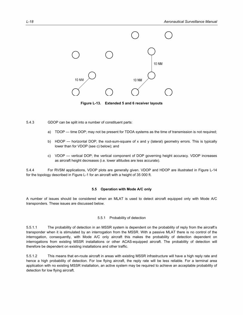
L-18 Aeronautical Surveillance Manual
Figure L-13. Extended 5 and 6 receiver layouts
5.4.3 GDOP can be split into a number of constituent parts: a) TDOP — time DOP; may not be present for TDOA systems as the time of transmission is not required; b) HDOP — horizontal DOP; the root-sum-square of x and y (lateral) geometry errors. This is typically
lower than for VDOP (see c) below); and c) VDOP — vertical DOP; the vertical component of DOP governing height accuracy. VDOP increases
as aircraft height decreases (i.e. lower altitudes are less accurate). 5.4.4 For RVSM applications, VDOP plots are generally given. VDOP and HDOP are illustrated in Figure L-14 for the topology described in Figure L-1 for an aircraft with a height of 35 000 ft.
5.5 Operation with Mode A/C only A number of issues should be considered when an MLAT is used to detect aircraft equipped only with Mode A/C transponders. These issues are discussed below.
5.5.1 Probability of detection 5.5.1.1 The probability of detection in an MSSR system is dependent on the probability of reply from the aircraft’s transponder when it is stimulated by an interrogation from the MSSR. With a passive MLAT there is no control of the interrogation, consequently, with Mode A/C only aircraft this makes the probability of detection dependent on interrogations from existing MSSR installations or other ACAS-equipped aircraft. The probability of detection will therefore be dependent on existing installations and other traffic. 5.5.1.2 This means that en-route aircraft in areas with existing MSSR infrastructure will have a high reply rate and hence a high probability of detection. For low flying aircraft, the reply rate will be less reliable. For a terminal area application with no existing MSSR installation, an active system may be required to achieve an acceptable probability of detection for low flying aircraft.

Appendix L. MLAT L-19
Figure L-14. GDOP for receiver layout as in Figure L-1
5.5.2 Code swaps 5.5.2.1 It is not always possible to distinguish Mode 1, 2, 3/A or C transmissions from an aircraft’s transponder unambiguously without reference to additional information. 5.5.2.2 For civil aircraft, the system has to determine the difference between Modes A and C. Mode C uses only 2 048 codes compared to the 4 096 used by Mode A. It is therefore possible to positively identify 50 per cent of Mode A codes by the presence of the D1 pulse as that pulse is not used in Mode C replies. The decoding of the remaining Mode A and C codes can be done in the tracking algorithms with reference to the measured height of the aircraft. This leaves some ambiguity in the result when the allocated Mode A code represents a Mode C altitude close to the measured height of the aircraft. The geometric height of a pressure altitude can vary by more than 1 000 ft. This means that there are more than twenty overlapping codes for any given flight level. The frequency of Mode A/C code swaps can be significantly reduced if the local barometric pressure is available. This will significantly reduce the number of overlapping codes. 5.5.2.3 Military aircraft introduce another level of ambiguity as they use Mode 1/2 as well as 3/A and C. Mode 1/2 can use all 4 096 codes and are therefore indistinguishable from Mode A without knowledge of the interrogation or current allocations. In high traffic areas there are many more A/C interrogations than Mode 1/2. This means that an assumption can be made based on the frequency of codes received from the target. 5.5.2.4 In summary, it is straightforward for an MLAT to associate a series of codes with an aircraft track. For civil aircraft it is possible to distinguish between the Mode A and C codes, although an ambiguity exists for a small number of codes. With military aircraft the ambiguity increases, especially between Mode A and Mode 1/2.
6. EXAMPLES OF WAM APPLICATIONS
6.1 En-route surveillance 6.1.1 This application involves long-range surveillance at typical altitudes of 29 000–41 000 ft. A typical WAM system with a square-5 layout and a large baseline of 60 NM and the following technical characteristics is generally considered suitable for en-route applications (see Table L-2):

L-20 Aeronautical Surveillance Manual
Table L-2. Assumed WAM characteristics
Parameter Value
Sensitivity –85 dBm
Reply rate factor 2.5
Antenna DME antenna with 3º squint
Bandwidth 22 MHz
Transmit power 24 dBW (typical SSR transmit power level)
Synchronization accuracy 1 ns
6.1.2 Figure L-15 shows accuracy versus range for both the aforementioned WAM and a typical MSSR calculated at the altitude of 35 000 ft. Only horizontal accuracy is shown as the MSSR cannot calculate height. If required, more outlying receivers could be added at the 60 NM baseline to form a pentagon, hexagon, etc. However, this would generally be done for availability or coverage reasons as it will not have a significant impact upon accuracy and thus is not shown in Figure L-15. 6.1.3 The plots in Figure L-15 assume 1 nanosecond synchronization accuracy, which can be achieved using a common-view GNSS synchronization method. For lower accuracy techniques there will be some degradation in horizontal accuracy and a more significant degradation in vertical accuracy. 6.1.4 The white area around the edge of the WAM plots indicates the maximum range the aircraft can be seen; with shorter baselines this area of no coverage will shrink, but the accuracy will rapidly decrease. Using a 60-NM range is considered to be a good compromise between these two opposing requirements, although it must be noted that not all synchronization architectures could support baselines of this size. However, this reduces overall coverage as not only the closest site is required to see the aircraft. For example, considering the left-hand graph in Figure L-15, in the north-east corner, not only the most north-eastern receiver must receive the SSR pulse but also the central site, and north-west and south-east receivers. This effect, common to all MLATs, implies the coverage will be limited by line-of-sight issues at shorter ranges than a single-site system.
Figure L-15. WAM versus MSSR accuracy (ft) for en-route surveillance

Appendix L. MLAT L-21
6.1.5 In order to extend the WAM coverage above approximately 180 NM, three options exist: a) Form a contiguous single system comprised of many receivers, as shown in Figure L-16; b) Utilize multiple sets of receivers similar to that shown in Figure L-17; and c) Raise site heights — this is likely also to be required for MSSR to ensure that coverage is available to
the full 250 N. 6.1.6 Where coverage extends a large distance beyond the baseline, it is probable that the second option will be more cost-effective with discrete subsets of sites forming the overall system. A single processing site can still be used if the synchronization architecture will support the large baselines required. 6.1.7 It is evident that within the coverage area, the WAM system offers far better accuracy than MSSR except at very short ranges (<10 NM) where similar results can be achieved (see Figure L-15).
Figure L-16. Extended multiple-receiver layout
Figure L-17. Extended multiple-system layout

L-22 Aeronautical Surveillance Manual
6.2 Terminal area surveillance 6.2.1 Terminal area surveillance is typically needed at a lower altitude and shorter range as compared to en-route surveillance. Figure L-18 shows accuracies of a typical MSSR, and Figure L-19 shows a number of WAM systems with different baselines for ranges up to 60 NM at both 1 000 and 3 000 feet. 6.2.2 As shown in Figure L-19, where sufficient coverage exists, a WAM system will generally outperform MSSR for accuracy. At these low heights, line-of-sight visibility dominates over sensitivity and antenna requirements. 6.2.3 The graph in Figure L-20 illustrates the drop in coverage with increasing baseline assuming the maximum distance a receiver can see is 38.9 NM (1 000 ft based on the equivalent earth radius factor of 4/3). It can be seen that for an aircraft at 1 000 ft, a zero-length baseline provides the maximum range of 38.9 NM. As the baseline is increased, the range of the system at 1 000 ft will reduce. When the baseline reaches 38.9 NM, it is no longer possible to see any aircraft at 1 000 ft because an insufficient number of receivers will see the aircraft.
6.3 Validation of ADS-B performance WAM may be used to monitor the performance of ADS-B systems. There are a number of roles that multilateration could play, as follows: a) Verification of navigation accuracy. The ADS-B data can be checked against the multilateration data to
verify the track-keeping performance of the avionics; b) ADS-B integrity monitoring. WAM can be used to monitor the integrity of ADS-B as a surveillance
technique. This could be done to gather data for a safety case and to monitor the integrity of in-service systems. For example, a bias in one aircraft’s position is a serious safety issue for ADS-B only surveillance, but a WAM system could identify this immediately;
c) Anti-spoofing. ADS-B is vulnerable to spoofing. WAM systems can be used to identify genuine aircraft
and the source of spoof transmissions; and d) Migration path to ADS-B. WAM can provide ground-based surveillance similar to existing MSSR type
surveillance. In addition, each receiver can operate as a 1 090 ADS-B receiver providing surveillance for both ADS-B and non-ADS-B traffic.
Figure L-18. MSSR accuracy (ft) in terminal area

Appendix L. MLAT L-23
Figure L-19. WAM accuracy (ft) in terminal area
Figure L-20. Maximum coverage at 1 000 ft with increasing baseline
______________________
0
Max
imum
rang
e fro
mce
ntra
l site
/ NM
10 20
Baseline/NM
30 400
10
20
30
40


M-1
Appendix M
INTERFERENCE CONSIDERATIONS
1. OVERVIEW 1.1 In the ATC environment SSR, ADS-B, ACAS and military of IFF systems use the same frequencies (1 030 MHz and 1 090 MHz) (see Figure M-1). Technical or operational changes in one of the aforementioned systems have impact on the system itself, within the system concerned, on the other systems operated on the same frequencies and even on systems operated on neighbouring frequencies (e.g. DME). Figure M-2 gives an overview of the 1 030/1 090 MHz systems as part of the aeronautical frequency band 960 MHz–1 215 MHz. MLATs do not necessarily need, but may use, active interrogations. 1.2 The availability of free time on both 1 030 MHz and 1 090 MHz frequencies in any given airspace depends on the number and distribution of aircraft, ground/airborne interrogators and their interrogation rates. Since in most cases each interrogator operates independently of the others, it suffers from interference by replies generated in response to interrogations from other ground or airborne sensors and also from the possible absence of replies from transponders that are being occupied by other interrogators at the time access is being attempted. 1.3 Interference can result in a degradation of system performance causing lost or wrong information. The reasons for this degradation are mainly transponder occupancy and RF signal distortion. Transponder occupancy prevents valid signals arriving at the transponder from triggering the desired reply. RF signals on either uplink or downlink can be distorted by other overlapping RF signals which can make correct decoding of wanted signals difficult or impossible. The extent of degradation is a function of the channel loading. 1.4 For example, a Mode A/C transponder can give false information if a Mode C interrogation is converted to an apparent Mode A interrogation. This can happen by an interference pulse from another interrogation falling in a position 8 microseconds or possibly 13 microseconds after the genuine P1 pulse. Also, if an interference pulse falls into a Mode A or C spacing before P1, a reply will be generated at the wrong range and possibly in the wrong mode. Lost information occurs when the transponder is interrogated when it is either in suppression or in the process of replying to an interrogation from another interrogator. 1.5 When a Mode S transponder is operating in a Mode A/C-only ground station environment, the interference considerations are identical to those for Mode A/C transponders. The introduction of Mode S ground stations into such an environment will, however, result in different interference mechanisms, the effect of which will depend on many factors including the number of Mode S and Mode A/C transponders and the particular Mode S protocol in use. The effects of ACAS in such an environment are in some respect similar to those of a Mode S ground station but can result in other interference mechanisms due to the higher interrogator density. 1.6 The interference phenomena are different for uplink and downlink. In an environment where Mode A/C and Mode S equipment are used in the same airspace, the effect of interference is different for each system. For example, a Mode A/C transponder is suppressed by a Mode S interrogation while a Mode S transponder will process the interrogations and reply if it is correctly addressed. 1.7 SSR system-generated interference can be minimized by: a) using the lowest transmitter power level possible, consistent with desired performance; and

M-2 Aeronautical Surveillance Manual
b) ensuring that interrogation rates are as low as possible and are not synchronous with any ground station having overlapping cover.
1.7.1 PRF stagger can also be used, thus ensuring that synchronous interference does not take place. 1.8 The transponder cannot process incoming RF signals for interrogation acceptance under the following conditions: a) if it is suppressed on its internal aircraft suppression bus due to RF transmission from other avionics
equipment (e.g. ACAS, UAT, DME); b) if it is in a transaction cycle; or c) if it cannot decode Mode A/C signals when a P1-P2 suppression pair has been received (until the
suppression period is over). 1.9 An important consideration in reducing channel activity is having the minimum number of interrogators in any given airspace consistent with operational requirements. The combination of II and SI codes makes it possible to uniquely identify 78 different interrogators or clusters. This unique identification capacity has been provided to facilitate the assignment of ICs. 1.10 Where possible, Mode S ground interrogators should be operated in a cluster. This eases the IC requirements and reduces interference on the downlink channel since subsequent acquisition will be undertaken by the ground coordination network within the cluster.
Figure M-1. Civil 1 030/1 090 MHz environment
interrogation (1 030 Mhz)
reply (1 090 Mhz)
RA-broadcast
RA-broadcast
ACAS
TIS-BADS-B
TIS-Bground station

Appendix M. Interference Considerations M-3
Figure M-2. Channel and frequencies within the aeronautical
frequency band 960 MHz–1 215 MHz
2. THE USE OF STOCHASTIC LOCKOUT OVERRIDE The Mode S-only all-call can provide the basis for acquisition of Mode S aircraft for interrogators that need the identity information available via Mode S but are not able to have an II code assigned for full Mode S operation. See Appendix F for details of this technique of acquisition.
3. MILITARY OPERATIONS
3.1 General 3.1.1 The reliable identification of objects in the airspace within the scope of continuous and area-covering production of a current air picture is an essential precondition for maintaining the integrity and security of the airspace over a State’s territory. 3.1.2 The frequency range around 1 030/1 090 MHz is subject to joint civil and military use. As such, in order to ensure the integrity of air navigation systems, limitations may need to be placed on military operations, exercises and training activities in peace time.
New IFF
IFF Mk X/XII
ACAS
military ACAS
ADS B
1 000 1 100 1 150 1 050 1 215
1 200 1 030 1 090
DME/TACANMHz
Interrogation Reply
Reply channels 256 interrogation and
SSR Mode A/C
SSR Mode S
TIS B

M-4 Aeronautical Surveillance Manual
3.1.3 Therefore, the frequency availability/clearance for certain military operations may only be granted with limitations and restrictions with respect to transmit power in certain directions, modes of operation, use of interrogation modes, etc. 3.1.4 As a precaution, points of contact should be defined for coordination purposes.
3.2 Mobile interrogators 3.2.1 In addition to fixed ground stations, military authorities may use mobile interrogators (e.g. shipborne radars). Therefore, agreements between civil and military authorities should be in place to allow such uses but at the same time they should be conducted in such a way as to ensure safe operation for all users at all times. 3.2.2 In general, through the nomination of authorized points of contact on both civil and military sides, it should be possible to immediately terminate and cease any operation that causes safety hazards. In this regard, restrictions on areas, times, operation and interrogation modes may be applicable. 3.2.3 The density, transmission characteristics and interrogation modes used by mobile interrogators may have a negative impact on the safe operation of ATS in certain areas. Authorities may wish to restrict the operation of mobile interrogators within the vicinity of major airports. This may limit or even forbid interrogations in a terminal area for some or all interrogation modes. Another possibility is the definition of a minimum distance to a major airport or a terminal area, in which mobile interrogators may be operated, together with a maximum interrogation power in certain directions. 3.2.4 The operation of airborne interrogators requires special care, and because of the interrogator height, a large area can be affected. It is therefore recommended that airborne interrogators use target specific interrogations and operate only according to mission requirements. 3.2.5 Typically, Mode S mobile interrogators should use II Code ZERO (0) in order to avoid conflicts with fixed Mode S interrogators. Appendix F contains more details on this subject.
4. MLAT 4.1 Multilateration is basically a passive system but it may use interrogations to achieve a certain level of performance. Active WAM systems can be used in approach and en-route environments. However, care must be exercised to limit the interrogation. In such cases, selective interrogations have the dominant effect on the transponder availability because of the use of omnidirectional antennas. 4.2 Significant levels of ACAS interrogations may reduce the transponder availability to a point that roll-call retries start to become a significant factor. However, this will be mitigated by a dynamic active WAM, which could abate roll-call in the presence of ACAS altitude reports.
5. ACQUISITION SQUITTER AND ES
5.1 General 5.1.1 There is an option to suppress the acquisition squitter in the future. With the rapid implementation of ADS-B OUT this option can help overcome detrimental FRUIT effects in high traffic densities. In addition, the specified maximum rate of 6.2 ES’s per second is near the limits in high traffic density areas. In this respect, the RF environment should be monitored to ensure that appropriate measures can be taken when necessary.

Appendix M. Interference Considerations M-5
5.1.2 Acquisition squitter can be disabled when all ACAS are able to operate with ES. In that case, acquisition squitters will only be transmitted when no data are available to populate ES messages. Disabling the periodic acquisition squitter transmissions when ES’s are available will reduce DF = 11 FRUIT significantly. However, the additional FRUIT (due to all aircraft emitting ES) is higher than the DF = 11 FRUIT reduction. 5.1.3 In general, it has to be recognized that a high performance receiver may suffer in a high density environment from high FRUIT rates, hence not providing a better performance than a “normal” receiver. On the other hand, a high performance receiver will increase the coverage substantially in low density airspace.
5.2 Continuous use of ES’s at maximum rate The 1 090 MHz downlink channel is being affected by the transmission of ES’s because of an increasing number of suitably equipped aircraft. In areas with high aircraft densities, even the 1 030 MHz uplink channel is affected by a continuous squitter rate of 6.2 Hz due to additional Mode S re-interrogations. Although the number of re-interrogations is increased, the loss of performance owing to the additional channel load cannot be completely compensated.
5.3 Ground-based broadcast 5.3.1 Traffic information or flight information could be of interest for general aviation and may be offered via point-to-point or broadcast transmissions. 5.3.2 Within an area of low aircraft density, the performance of an SSR is only marginally affected by the operation of a nearby 1 090 MHz transmitting ground station. On the other hand, in areas of higher air traffic density, Mode A/C and ACAS performances can be reduced significantly. 5.3.3 The impact on the performance of a Mode A/C SSR will be higher, if omni-antenna-equipped ADS-B/TIS-B stations are widely deployed (i.e. not just as gap fillers). The effect on Mode S detection should be negligible because of the fact that a re-interrogation can be initiated in the case of failure. 5.3.4 If a 1 090 MHz ground-based broadcast is used area-wide, more critical situations will occur, since an SSR site may be affected by more than one station. In this case, the total 1 090 MHz signal load at the SSR is at least the sum of the individual broadcast contributors. Precautions should be taken to ensure that the transmissions from broadcast ground stations will be below appropriate signal levels to minimize the impact on surveillance infrastructure and ACAS.
6. ACAS INTERFERENCE LIMITING ACAS is capable of operating in all traffic densities without unacceptably degrading the RF environment. Each ACAS knows the number of other ACAS units operating in the local airspace. This knowledge is used in an attempt to ensure that no transponder is suppressed by ACAS activity for more than two per cent of the time and that ACAS does not contribute to an unacceptably high FRUIT rate that would degrade ground systems surveillance performance. Multiple ACAS units in the vicinity cooperatively limit their own transmissions. As the number of such ACAS units increases, the interrogation allocation for each of them decreases. Thus, every ACAS unit monitors the number of other ACAS units within detection range. This information is then used to limit its own interrogation rate and power as necessary. More details can be found in the Doc 9863.

M-6 Aeronautical Surveillance Manual
7. NEW SYSTEMS AND APPLICATIONS 7.1 Systems using Mode S capabilities are generally used for ATC surveillance. In addition, certain ATC applications may use Mode S emitters for surface vehicle surveillance or for fixed target detection. Under such conditions, the term “aircraft” can be understood as “aircraft or vehicle (A/V)”. While those applications may use a limited set of data, any deviation from standard physical characteristics must be considered very carefully by the appropriate authorities taking into account not only their own surveillance environment but also possible effects on other systems like ACAS. 7.2 In general, new systems or applications should not unduly affect the existing ATM environment. Therefore, thorough investigations by civil aviation authorities are necessary prior to any new system deployment to ensure compatibility with existing services.
8. TRANSPONDER OCCUPANCY
8.1 General A transponder is occupied from the time it detects an incoming signal that appears to cause some action (e.g. a valid interrogation or suppression pair) to the time that it is capable of replying to another interrogation (including turnaround delay, reply time and dead time).
8.2 Being in the main beam of a Mode S ground station 8.2.1 A Mode A/C transponder will be occupied in the normal way to Mode A/C interrogations, but in addition, it will be suppressed for every Mode S interrogation made. Note.— Mode A/C transponders treat intermode interrogations as conventional Mode A/C interrogations. 8.2.2 A Mode S transponder will be occupied by all Mode S interrogations specifically addressed to it. Mode S-only all-call and broadcast interrogations will also occupy the transponder. The transponder will also be occupied by intermode interrogations with a long P4. Transponder occupancy by both types of all-call interrogations can be minimized by using the lockout protocol. 8.2.3 A Mode S transponder will also be occupied by the receipt of any Mode S interrogation addressed to another aircraft. The transponder must fully decode the interrogation to determine the 24-bit address contained in the message block. Once the transponder determines that the interrogation is intended for another transponder, it will resume normal operation. This activity will nominally require 45 microseconds.
8.3 Being in the side lobes of a Mode S ground station 8.3.1 A Mode S transponder will be occupied by a Mode S interrogation specifically addressed to it. This should not normally happen in the side lobes. The transponder will however be occupied to Mode A/C for the suppression period after the receipt of every P1-P2 pair. However, during and after the receipt of a Mode S side lobe interrogation, the Mode S transponder will not be able to detect valid interrogations which are below the current threshold up to the time of recovery to full sensitivity. 8.3.2 A Mode A/C transponder will be occupied by the normal suppression for Mode A/C and intermode interrogations.

Appendix M. Interference Considerations M-7
8.3.3 It is important to note that a Mode A/C transponder will be suppressed by every Mode S interrogation, including broadcast and Mode S-only all-call interrogations, made by that ground station. 8.3.4 If selectively addressed Mode S interrogations are transmitted without an accompanying P5 suppression pulse, all transponders receiving the interrogation will be occupied until the interrogation has been fully decoded. If the interrogation is accompanied by a P5 pulse, the transponder is only prevented from decoding other interrogations until the sync phase reversal recognition fails, followed by the receiver recovery time.
8.4 Selective Mode S transponder occupancy The Mode S protocols provide the facility to lock out the transponder to all types of all-call interrogations requiring a Mode S reply. This can be regarded as permanent occupation of the transponder to that type of interrogation and great care must be exercised to ensure that the use of these protocols does not prevent other ground stations with a need to acquire the transponder through all-call interrogations from doing so. See Appendix H for additional information on lockout management.
8.5 Interaction with other on-board equipment using the same frequency band
As indicated in Figure M-2, several devices on board the aircraft use the same frequency band. A mutual suppression system may be used to connect onboard equipment operating in the same frequency band (e.g. between a DME, ACAS and an SSR transponder) in order to prevent mutual interference and receiver damage. The receivers of the other devices are suppressed during the time mutual suppression is active. As a result, the availability of the transponder for interrogations is reduced, i.e. the transponder occupancy is increased.
8.6 Table of transponder occupancy for different interrogations The total occupancy is made up of several nominal times as listed in Table M-1. The term “transponder transaction cycle”, defined in Annex 10, Volume IV, Chapter 3, 3.1.2.4, is used for Mode A/C transponders in the same manner as for Mode S transponders. (The time for an additional SPI in a Mode A/C reply is not included). Note.— The total processing times for all interrogation types are listed in Table M-2. The items in parentheses are references to the rows of Table M-1.
9. CHANNEL LOADING
9.1 General 9.1.1 Channel loadings are different on uplink and downlink. For conventional SSR systems (Mode A/C), one interrogation is replied to by all transponders receiving that interrogation. Thus the downlink loading is considerably higher than that of the uplink. 9.1.2 When the selective interrogations of a Mode S ground station are used, each selective interrogation normally triggers only one reply. This leads to a more balanced channel loading in terms of the number of transmissions. Since the uplink transmission bit rate of 4 MHz is four times greater than that of the downlink, the total channel occupancy time on the uplink is also only 1/4 of the downlink loading for equivalent transactions.

M-8 Aeronautical Surveillance Manual
Table M-1. Relevant times for transponder occupancy
Mode A/C Intermode Mode S short Mode S long
a) Interrogation
a1) signal duration 8.8 µs 21.8 µs
10.8, 11.6 µs 23.8, 24.6 µs
19.75 µs 33.75 µs
a2) referenceb 8 µs 21 µs
11.6 µs 24.6 µs
4.75 µs 4.75 µs
b) Transaction eventsa
b1) reply delay 3 µs 128 µs 128 µs 128 µs
b2) reply duration 20.75 µs 64 µs 64 µs 120 µs
b3) transaction cycle: reply 23.75 µs 192 µs 192 µs 248 µs
b4) transaction cycle: no reply 15 µs 29 µs
c) Dead time up to 125 µs up to 125 µs up to 125 µs up to 125 µs
d) Suppression
d1) signal duration 2.8 µs — 19.75 µs 33.75 µs
d2) referenceb 2 µs — 4.75 µs 4.75 µs
d3) suppression interval 35 µs — — —
e) Recovery
e1) single pulse, interference up to 15 µsc up to 15 µsc up to 15 µsc up to 15 µsc
e2) interrogation not eliciting a reply
— — 45 µs 45 µs
Notes: a) Starting at reference. b) Timespan from the beginning of the signal. c) Depending on the signal amplitude beginning at the trailing edge of the signal (last pulse). d) Additional suppression can be caused by other onboard transmitters via the suppression bus, e.g. ACAS and DME. A typical
suppression duration is 70 µs.
9.2 Uplink loading 9.2.1 The uplink channel loading should be measured or defined at the antenna of any aircraft in terms of interrogations per time unit or time occupancy. The loading is dependent on the location of an aircraft (i.e. the distance to a ground station and the flight level) which determines how many ground stations are illuminating it. 9.2.2 Inside the side lobes of a ground station antenna, an aircraft receives continuously all interrogations from the ground station. Since this area is normally controlled by an omni-suppression technique, suppression pulses will also be received.

Appendix M. Interference Considerations M-9
Table M-2. Table of transponder processing times
Note.— The items in parentheses are references to the rows in Table M-1.
Total transponder processing timea,b
Received signals Mode A/C transponder Mode S transponder
P1P3, Mode A Mode C
156.75 µs (a2+b3+c) 169.75 µs (a2+b3+c)
156.75 µs (a2+b3+c) 169.75 µs (a2+b3+c)
P1 P3P4 short, Mode A Mode C
156.75 µs (a2+b3+c) 169.75 µs (a2+b3+c)
26.6 µs (a2+e1) 39.6 µs (a2+e1)
P1 P3P4 long, Mode A Mode C
156.75 µs (a2+b3+c) 169.75 µs (a2+b3+c)
328.6 µs (a2+b3+c) 341.6 µs (a2+b3+c)
P1P2 37 µs (d2+d3) 47 µs (d2+d3) for Mode A/C
4.75 µs (a2) for Mode S
P1P2P5P6 37 µs (d2+d3) 4.75 µs (a2)c
P1P2P6 correctly addressed, short reply long reply 37 µs (d2+d3)
321.75 µs (a2+b3+c) 377.75 µs (a2+b3+c)
P1P2P6 not addressed 37 µs (d2+d3) 49.75 µs (a2+e2)
no received signal
Squitter, short long —
189 µs (b2+c) 245 µs (b2+c)
Notes: a) Additional effects may occur due to reply rate limiting. b) The maximum value of dead time (125 µs) is used in the processing times values calculated in the
table. Typical values are significantly lower. c) In this case the incoming RF signal extends beyond this time and other incoming signals will only
be decoded if they are sufficiently above the receiver threshold set by the original signal.
9.2.3 Outside the side lobes, the loading is due to the limited effective beamwidth of a rotating antenna and on the time when the beam sweeps through an aircraft. 9.2.4 Considering an aircraft being in the main beam of a Mode S ground station antenna, the channel loading originating from that ground station is a function of the number of aircraft being selectively interrogated and of the degree of activity for surveillance and/or data link purposes. The channel loading is a function of the azimuth but can also vary with time. 9.2.5 The overall loading is also dependent on the total number of ground stations interrogating the aircraft, measured during an interval of the order of 1 minute. This loading represents a mean value, whereas during such an interval, considerably higher peak values can be measured. 9.2.6 Since the channel loading is heavily dependent on the scenario, i.e. the number of ground stations, type and number of interrogations, number of aircraft and their type of equipment, only some examples for typical scenarios can be given.

M-10 Aeronautical Surveillance Manual
9.2.7 The replacement of a conventional ground station, using sliding window techniques, with a Mode S ground station reduces the Mode A/C interrogation rate due to the use of the monopulse technique. In this case, the all-call interrogation rate is typically between 100 and 150 per second. Assuming an effective beamwidth of 3.6 degrees and an antenna rotation time of 5 seconds, an aircraft located in the main lobe would receive between five and eight all-call interrogations during each scan. Inside the side lobes the aircraft would receive all interrogations, i.e. 100 to 150 per second. When intermode interrogations can be used to acquire Mode S transponders, the same interrogation rate applies. 9.2.8 A Mode S-equipped aircraft may be selectively interrogated during a beam dwell time of 50 milliseconds with up to 15 surveillance or Comm-A interrogations. A 16-segment uplink ELM may be transferred during this time, whereby replies required for ELM delivery reduce the number of such interrogations. These figures are derived from the minimum reply rates for Mode S transponders. 9.2.9 From highly loaded scenarios it is known that up to 15 aircraft can be simultaneously within the beam, while typical values are about five to eight aircraft. Assuming all aircraft are equipped with Mode S transponders and have high data link activity, the number of Mode S interrogations can be in the order of 100 during a beam dwell, which would produce (in the given example) a peak interrogation rate of 2 000 per second. The maximum repetition rate for selective interrogations is limited to 2 400 per second averaged over a 40-millisecond interval. 9.2.10 For the delivery of an uplink ELM, the interrogation segments are normally closely spaced. Therefore, they represent a higher potential for interference compared with surveillance or Comm-A interrogations.
9.3 Downlink loading 9.3.1 The downlink loading should be measured or defined at the antenna of a ground station. This loading is a function of the number of aircraft within coverage (contributing with surveillance replies, replies to ACAS interrogations, plus acquisition and ES), the number of interrogations from other ground stations interrogating the same aircraft in the same time period and broadcast transmitters (TIS-B and ADS-R). 9.3.2 In the case of surveillance and SLM transactions, the downlink loading corresponds to the uplink loading since a reply can only be triggered by an interrogation. It should be noted, however, that each Mode S transponder also transmits an acquisition squitter reply once each second. In addition, an ADS-B capable Mode S transponder transmits up to 6.2 ES’s per second. 9.3.3 All replies triggered by other ground stations are named FRUIT, so that the Mode A/C and Mode S FRUIT rate corresponds to the degree of uplink loading in the environment of the ground station where the FRUIT rate is determined.
10. SSR GARBLING 10.1 SSR replies from transponders can be corrupted by other signals arriving at the same time at the interrogator receivers. Interference that leads to the corruption of the reply is referred to as garble. There are two types of garble: a) asynchronous garble — where the SSR reply is corrupted by a random signal that is not synchronized
with the SSR interrogations; and b) synchronous garble — where the SSR reply is corrupted by other replies to the same interrogator.

Appendix M. Interference Considerations M-11
10.2 Asynchronous garbling rarely causes the corruption of the complete radar plot data for an aircraft. This is because the SSR system transmits several interrogations to each aircraft as the beam sweeps past. It is unlikely that random interference will corrupt all of the replies in the beam. The radar performs an averaging function of the replies that correlate across the beam reducing the impact of any random errors. Also, the radar typically performs scan-to-scan or track correlation, which may have further error correcting functions that depend on the history of the aircraft track in the system. The most common source of signals leading to asynchronous garble are the replies of aircraft responding to other interrogators and ACAS. This is why it is important to operate neighbouring interrogators with different PRF and to operate random PRF stagger functions (in order to ensure that the interrogators remain unsynchronized). 10.3 Synchronous garbling occurs when aircraft close to each other in slant range respond to the same interrogation. Depending on the range difference between the aircraft, the reply pulses may overlap or interleave with each other. A standard SSR Mode A or C reply is approximately 1.7 NM long, therefore aircraft within this distance of each other and at close azimuths (i.e. within the antenna beamwidth) have a chance of the reply pulses overlapping each other. Because the replies from all aircraft are synchronized to the interrogator, multiple replies across the beam may be corrupted, which may cause the reply averaging function of the radar to produce an erroneous result. If the garble situation persists from scan to scan, then the radar track history error correcting functions may also be corrupted, and the following may result: a) incorrect Mode A code for the aircraft; b) incorrect Mode C (flight level) for the aircraft; c) code swaps, where the wrong Mode A and/or Mode C data are associated with the aircraft; or d) phantom aircraft, where the overlapping reply pulses form a reply that appears to be coming from two
real aircraft. 10.4 Synchronous garbling can occur when aircraft are at close azimuths and slant ranges, even where there may be large altitude separation. Such garbling can persist for several scans. Situations where synchronous garbling can occur include: a) aircraft in a stack are moving around directly above and below each other; b) groups of gliders riding the same thermal flying small circuits above and below each other; c) aircraft flying in the same airway at similar range and speed; d) aircraft tracks crossing at a coincident range and azimuth; e) helicopters converging (e.g. to provide television coverage of some events); and f) recreational flying events where multiple aircraft converge. 10.5 Persisting synchronous garble situations should be avoided by carefully directing traffic to avoid loss of range and azimuth separation, even where altitude separation is being maintained. 10.6 Mode S radars employ certain techniques to avoid synchronous garble. During all-call acquisition, stochastic reply functions are employed to de-garble all-call replies where aircraft are in close proximity of each other. During roll-call surveillance, each aircraft is individually interrogated, thus avoiding synchronous garble.

M-12 Aeronautical Surveillance Manual
11. RF INTERFERENCE FROM OTHER SYSTEMS 11.1 The SSR system requires a 3 dB receiver bandwidth of approximately 8 MHz centred on 1 030 and 1 090 MHz for both airborne transponder and ground receiver. This bandwidth is sufficient to permit significant co-channel interference from transmitters operating on adjacent frequencies. This interference can be minimized by ensuring adequate frequency or spatial separation between the interfering transmitters and the subject SSR receivers. In particular, DME and primary radar can be the cause of interference. DME channels adjacent to the SSR frequencies can cause interference to SSR. Some primary radar transmitters make use of two frequencies which, if separated by 60 MHz, can cause intermodulation products causing interference to collocated SSR systems. 11.2 Any incoming signal may cause the transponder to miss a valid interrogation. The duration of the interference depends on the signal source, the signal duration on the 1 030 MHz channel and the signal amplitude at the transponder antenna. 11.3 There have been various approaches to use the SSR frequencies for other purposes (e.g. for obstacle warning at wind farms using active interrogations). These applications are not acceptable, at least in medium to high density airspace, as the performance of existing systems can be degraded significantly. An appropriate approach in particular for obstacle warning would be the use of the standardized ADS-B message BDS 0,8 code set C (for details see Doc 9871).
12. RECOMMENDATIONS FOR 1 030/1 090 MHZ CHANNEL MANAGEMENT
12.1 General In general, the efficient use of the 1 030/1 090 MHz environment through transmission management, interrogation rate management and the appropriate antenna design for each system is a prerequisite to ensure proper operation of all systems using those and the neighbouring frequencies.
12.2 Radar environment 12.2.1 The dominant form of FRUIT by 2015 is likely to be Mode S. Radar infrastructure rationalizations, interrogator power and interrogation rate management, and antenna design could lead to significant FRUIT level reductions. Moreover, FRUIT can be significantly reduced by: a) clustering of Mode S radar; b) regional ground system coordination; c) improved cooperation between civil and military authorities; and d) use of correctly tested and maintained equipment. 12.2.2 The modes of operation of civil and military radars have a large effect on the amount of interference produced by them. Decoding 1 090 ES messages in the presence of Mode S FRUIT (either from other 1 090 ES messages, acquisition squitters, ACAS or replies to Mode S radars) is significantly more challenging than decoding those in the presence of Mode A/C FRUIT. Therefore, a coordinated and agreed transition to Mode S by all parties is beneficial.

Appendix M. Interference Considerations M-13
12.3 Airborne surveillance 12.3.1 Even if the ground equipment is not changed, equipping more aircraft with Mode S transponders will reduce the 1 090 MHz channel load. Moreover, ACAS performance will be improved and its interrogation/reply rates will be reduced if hybrid surveillance is widely implemented. Aircraft equipped with the new ACAS hybrid surveillance equipment will be able to acquire other aircraft on the basis of ES. 12.3.2 With the increasing carriage of ACAS and the increasing traffic densities, investigations are necessary to improve ACAS interference limiting for future aircraft densities, while ensuring acceptable levels of performance for all surveillance systems. 12.3.3 The use of airborne surveillance equipment not internationally standardized (e.g. TCAS I) may not be permitted in some States or regions. Such equipment is likely to generate additional channel load which may degrade the performance of ground-based and airborne surveillance systems. For TCAS I, there are currently two implementations that use either ACAS I or ACAS II interference limiting. The latter violates existing ICAO provisions in Annex 10, Volume IV, when it is expanding its surveillance range, thus potentially degrading the performance of other surveillance systems. An implementation with ACAS I interference limiting can generate excess FRUIT in high traffic densities without providing the expected benefit, as the probability of detecting other targets can degrade to unacceptable levels.
12.4 ADS-B ES 12.4.1 The increase in FRUIT through transmission of ES by a large number of aircraft cannot be adequately compensated by deploying hybrid surveillance. The specified maximum rate of 6.2 ES’s per second is at the limits in high traffic density areas. Some compensation can be achieved by disabling the transmission of acquisition squitters to reduce the overall FRUIT load and to improve ACAS surveillance performance. This, however, requires new ACAS equipment. 12.4.2 There are ICAO provisions to suppress the acquisition squitter in the future. With the rapid implementation of ADS-B OUT, this option can help overcome detrimental FRUIT effects. 12.4.3 Due to the expected effect of the use of squitter transmission in high density areas above the 6.2 squitter per second rate, it is recommended that there be investigation of the possibilities of adapting squitter rates and transmission power to the actual environment and application needs. This will ensure the usage of ES as a long-term ADS-B medium for global interoperability. 12.4.4 After a transition period beyond 2015, 1 090 MHz FRUIT is likely to decrease. Some radars are likely to be decommissioned and replaced by ADS-B stations leading to a reduction in interrogations and hence in FRUIT. In the following years, air traffic growth will eventually compensate for the reduction in interrogations, and furthermore, the level of 1 090 ES FRUIT will become more and more critical. Consequently, 1 090 ES system performance may initially improve for some period beyond 2015 but will gradually degrade later. 12.4.5 It will be important, however, to keep monitoring FRUIT levels and to perform follow-up studies on any changes in predictions for air traffic growth and the evolution of national plans for surveillance infrastructure. 12.4.6 Any implementation of TIS-B should be carried out very carefully. Specifically, the transmission rates should be as low as possible. Filling surveillance gaps could result in a safety benefit which justifies the additional channel load. However, adjacent or overlapping coverage should only be done in areas with low traffic densities.

M-14 Aeronautical Surveillance Manual
12.5 Future developments 12.5.1 In general, the move towards passive acquisition (e.g. ADS-B and multilateration) should be encouraged. Active MLATs should be designed to employ minimum interrogation rates and power in order not to have a negative impact on the surveillance environment. 12.5.2 Equipage of new user groups with Mode S transponders (for light aviation) or ACAS (for very light jets) needs careful investigation and analysis, as it may influence the operation of existing equipment on the ground and in the air.
______________________

N-1
Appendix N
ASTERIX INTERFACE SPECIFICATIONS
1. INTRODUCTION The ASTERIX specifications were developed in Europe in order to harmonize the transmission of surveillance information. ASTERIX specifications describe formats for the exchange of data between the surveillance sensors and data processing systems, and also for the generalized exchange of surveillance data between systems.
2. ASTERIX DOCUMENTATION The ASTERIX standard documentation is subdivided into parts: — Part 1: ASTERIX general description; and — Part 2 and other parts describe the individual categories, for example: — Part 4: Monoradar target reports (CAT048) — Part 12: ADS-B messages (CAT021) — Part 14: MLT messages (CAT020) — Part 17: Safety nets messages (CAT004)
3. ORGANIZATION OF DATA (see Figure N-1)
3.1 Categories Some examples of ASTERIX categories are: — CAT 001, 002 and 008: Used for radar data — CAT 004: Safety net data — CAT 007: Military use — CAT 017 and 018: Used for Mode S sensor coordination and data link function — CAT 019 and 020: Used for multilateration data

N-2 Aeronautical Surveillance Manual
— CAT 021, 023 and 033: Used for ADS-B data — CAT 034 and 048: Used for Mode-S radar data and other radar data — CAT 062: Used for multi-sensor data.
3.2 Data items A data item is the smallest unit of information defined and standardized. A catalogue of data items is defined for each category. Each data item has a unique reference: Innn/AAp, where: a) “I” indicates the data item; b) “nnn” is a three-digit decimal number indicating the category to which the item belongs; c) “AA” is a two-digit decimal number identifying the item; and d) “p” is a one-digit decimal number that may indicate up to ten different representations.
3.3 Data fields For communication purposes, data items are assigned to data fields. Each data field has a number and a certain length.
3.3.1 Standard data field formats These formats can be: a) fixed length; b) extended or variable length by using a field extension (FX) indicator; c) repetitive data fields by using a one octet field repetition (REP) indicator; or d) compound data fields using a primary subfield, followed by data subfields.
3.3.2 Non-standard data fields 3.3.2.1 In special purpose fields, the format is as follows: a) the first octet contains length, including length indicator; b) the data field may contain information such as test data, text for operator communication; and c) contents are agreed among some users, others may skip it. 3.3.2.2 In reserved expansion data fields, the format is as follows: a) the first octet contains length, including length indicator;

Appendix N. ASTERIX Interface Specifications N-3
Figure N-1. Organization of the data and categories
SURVEILLANCE RELATED DATA
DATA CATEGORY (n)
CATALOGUE OFDATA ITEMS FOR THIS CATEGORY
CATALOGUE OFDATA ITEMS FOR THIS CATEGORY
CATALOGUE OFDATA ITEMS FOR THIS CATEGORY
DATA ITEM (1)
DATA ITEM (2)
.
.
.
.
DATA ITEM (p)
DATA ITEM (1)
DATA ITEM (2)
.
.
.
.
DATA ITEM (q)
DATA ITEM (1)
DATA ITEM (2)
.
.
.
.
DATA ITEM (r)
DATA CATEGORY (1) DATA CATEGORY (2)

N-4 Aeronautical Surveillance Manual
b) the data field is intended to introduce intermediate changes; and c) contents are agreed by the committee managing ASTERIX and are described in a separate document.
3.4 User application profile The UAP defines the sequence of the catalogued data items of a specific category within the ASTERIX message. The FRN, allocated to each data item, defines the location of the item within the ASTERIX datastream. The UAP can be considered as a control table attached to the message assembly/disassembly programme resident in the relevant processing system. ASTERIX is based on an ordered field organization. The FSPEC indicates which item (identified by its FRN) is present in a message, and which is not. The FSPEC is an extendable length data field with a minimum length of one octet. The relationship between FSPEC and data fields is described in the UAP.
3.5 General message record structure An ASTERIX “record” is described as follows: a) it contains information of the same data category; b) it has an FSPEC of variable length, indicating the presence of data fields in the sequence defined by
the UAP; c) it has a variable number of data fields with implicit or explicit length. Each data field is associated with
one and only one data item, as defined in the UAP; and d) it is always a multiple of an octet long.
4. ASTERIX ADDRESSING SCHEME 4.1 ASTERIX contains an addressing scheme to identify the source providing the data. It is based on indicating the SAC and the SIC. SAC/SIC codes are always the first item in UAP. 4.2 SAC is an 8-bit number assigned to an area or country. It is subject to a central allocation currently managed by EUROCONTROL. SAC contains six tables: African, Asia and Pacific region, European, Middle East, North American (Canada and the United States), and South American and the Caribbean. The most current versions are published at: www.eurocontrol.int/asterix/public/ standard_page/sac_list.html 4.3 SIC is an 8-bit number assigned to every system within an area or country defined by SAC and is subject to local allocation.
______________________

O-1
Appendix O
AIRBORNE SURVEILLANCE EQUIPMENT INSTALLATION AND TEST CONSIDERATIONS
1. OVERVIEW 1.1 Mode S transponders are complex multi-tasking systems with numerous aircraft interfaces. Any technical problems in transponders or in systems that interface with them have impacts on the overall surveillance performance. Therefore, it is important that transponders, other related airborne equipment be designed, tested and installed in accordance with Standards and Recommended Practices, other relevant industry standards and applicable regulations. 1.2 Installations may change during the life of the aircraft and transponder software upgrades are becoming more frequent. It is therefore necessary to monitor transponder performance during the life of the system. This can be achieved during periodic maintenance of the aircraft as well as by using ground-based monitoring systems during flights.
2. GENERAL INSTALLATION CONSIDERATIONS
2.1 24-bit aircraft address 2.1.1 Most cooperative surveillance systems depend on the use of a unique 24-bit aircraft address. A block of 24-bit aircraft addresses is allocated by ICAO to each State of Registry or common mark registering authority to uniquely assign, from that block, an address to each individual aircraft. This unique address should be used by all installed avionics that are required to use the 24-bit aircraft address. Therefore, it is important that this address be correctly configured and verified during initial installation and testing. Note.— Annex 10, Volume III, Part I, Chapter 9, Appendix, contains information on the 24-bit aircraft-addressing scheme. 2.1.2 The 24-bit aircraft address can change during the life of an aircraft (e.g. when changing registration). Similarly, maintenance operations can result in connector pins being broken. It is therefore important that the operator regularly check that the 24-bit aircraft address is correct for the airframe. This should be checked at least after each maintenance operation on the transponder.
2.2 Inhibition of replies Annex 10, Volume IV, 3.1.2.10.3.10, requires the Mode S transponder to be inhibited from replying to Mode A/C/S all-call and Mode S-only all-call interrogations when the aircraft is on the ground. For aircraft with retractable landing gear, this is usually accomplished via an appropriate transponder pin connection to the weight-on-wheels switch. It can also be accomplished through some other automatic means (e.g. velocity/altitude algorithm). The inhibit means should be verified during initial installation and testing, as well as after any maintenance action (e.g. wiring change or software update).

O-2 Aeronautical Surveillance Manual
Note.— The aforementioned Annex 10 provision also requires the transponder to continue to output acquisition squitters, ES’s (e.g. ADS-B), and to reply to any discretely addressed interrogations while on the ground. These functions should also be verified during installation and testing of the inhibit function.
2.3 Mutual suppression Mutual suppression is used on aircraft that are equipped with other L-band transmitting devices to protect receivers from high-power transmissions while any device is transmitting. These devices or systems are normally connected together using a mutual suppression interface bus or line. The transmitting device sends a pulse to notify other L-band systems residing on the suppression bus or line when a transmission is active. It is necessary to protect the integrity of the interface in case of a failure caused by any single device or system. Care should be exercised before installation to ensure compatibility of the mutual suppression interface between or among the systems to be interconnected. Installation tests should include verification that the mutual suppression interface is operating properly.
2.4 Flight identification (flight ID) 2.4.1 Both ELS and ES (1 090 ES) functions of the Mode S transponder utilize the same information as contained in item 7 of the ICAO flight plan to identify aircraft. This information is named aircraft ID within the message formats. 2.4.2 For privately operated aircraft, the flight ID should reflect the aircraft’s registration mark (e.g. N123GA). Consideration should be given to hard-coding the flight ID with this registration number at the time of initial installation so as to preclude the need for a cockpit input interface and to ensure the integrity of the information. The flight ID coding should be verified during initial installation and testing. 2.4.3 Where the flight ID changes (e.g. airline flight operations) a flight deck flight ID input interface will be required. In this case, the flight ID should be the appropriate ICAO 3-letter airline designator followed by the flight number. The input interface should be evaluated for proper flight ID encoding during initial installation and testing. Note.— Approved three-letter airline designators can be found in Designators for Aircraft Operating Agencies, Aeronautical Authorities and Services (Doc 8585).
2.5 Controls The operation of controls that are intended for use during flight should be designed and evaluated to ensure that they are logical and tolerant to human error. In particular, where transponder functions are integrated with other system controls, the manufacturer should evaluate the design layout of the control panel to ensure that the possibility of unintentional transponder mode switching (i.e. from an operational state to “STANDBY” or “OFF”) is minimized. In addition, with the trend toward increasing reliance on “line select” keys, “touch screens” or “cursor controlled/track-ball” methods of changing avionics operating modes, equipment installers need to evaluate the intended location of controls in the cockpit that will prevent inadvertent and incorrect flight crew activation. In locations where controls are still vulnerable to inadvertent activation, consideration should be given to requiring some form of flight crew confirmation.

Appendix O. Airborne Surveillance Equipment Installation and Test Considerations O-3
3. TRANSPONDER TESTING
3.1 Ground testing 3.1.1 When conducting any ground testing of the transponder or ACAS, it is most important to follow proper procedures to prevent interference to ATC operations or other ACAS aircraft operating in the area. Ground maintenance checks or ramp testing (such as altimetry or bearing accuracy testing) can cause data to be transmitted by the transponder that could produce false targets for the ground ATC surveillance systems or for airborne ACAS aircraft. These false indications of “intruder aircraft” could result in unnecessary ATC communications and possibly in ACAS-induced aircraft manoeuvres. The problem of false ACAS warnings is more noticeable when ground testing of transponders takes place at airfields located beneath terminal control areas or in the vicinity of control areas and zones where aircraft movements are numerous. 3.1.2 Ground testing should be conducted in coordination with ATC and by the use of antenna shielding (i.e. transmission absorption covers or caps) to adequately attenuate transmitted signals. Using high-powered, hangar-mounted transponders is NOT an acceptable means for conducting either ACAS or transponder ramp testing. The following guidelines should be followed to minimize the aforementioned risks: a) when not required, ensure all transponders are set to “off” or “standby”; b) before starting any test, the local ATC authority shall be notified of the intended transponder testing.
Information such as start time, test duration. aircraft ID (flight ID) and, if appropriate, the Mode A code to be used (subject to due coordination) should be provided to the ATC authority;
c) prior to switch-on, or with the transponder in “standby” mode, set the Mode A code to the
agreed/coordinated value; Note.— The Mode A code 7 776 is assigned as a test code in Europe, specifically for the testing
of transponders. In Australia, Mode A code of 2 100 is used for transponder testing. d) set the aircraft ID (flight ID) to the first eight characters of the name of the company that is conducting
the tests; e) set the on-the-ground status for all Mode S replies, except when an airborne reply is required (e.g. for
altitude testing); f) where possible, perform the testing inside a hanger to take advantage of any shielding properties it
may provide; g) as a precaution, use antenna transmission covers regardless of whether the testing is performed
inside or outside; h) when testing the altitude (Mode C or S) parameter, radiate directly into the ramp test set via the
prescribed attenuator; i) manually set the altitude to an unrealistically high value (i.e. over 60 000 ft); j) in-between testings (e.g. during transition from one altitude to another or changing the Mode A code),
set the transponder to “standby” mode before changing the input;

O-4 Aeronautical Surveillance Manual
k) when testing is complete, immediately set the transponder to “OFF” or “standby”; and l) simulation of ACAS operation must not be carried out by the radiating from an antenna located on the
ground (e.g. in a workshop). 3.1.2.1 Certification authorities should consider whether the current practices of testing transponders with different altitudes is still required for aircraft using serial inputs (as opposed to a “Gilham” encoder).
3.2 In-flight testing
3.2.1 A transponder in-flight tester may be provided to indicate normal or faulty operation. 3.2.2 When a tester is used, it should not radiate a signal level outside the aircraft that is stronger than –70 dBm. Moreover, the test interrogation signal should not exceed the rate of 450 per second. 3.2.3 The test should be limited to a short period that is just enough to determine the status of the transponder. Note.— As with ground testing of the transponder or ACAS, it is important to follow proper procedures to prevent being an airborne source of interference to ATC or other ACAS aircraft operating in the area.
4. ANSWERS TO FREQUENTLY ASKED QUESTIONS (Q = question; A = answer)
Q1. Does Annex 10 require the installation of a second transponder? A1. No. However, most civil operators install a second transponder to improve dispatch ability to airspace wherein a transponder is required. Q2. If I have not yet received my assigned 24-bit aircraft address from my State of Registry, or common mark registering authority, is it permissible to use ALL ZEROs (0’s) or ALL ONEs (1’s) until it is received? A2. No. At no time should you use ALL ZEROs (0’s) or ALL ONEs (1’s) as the 24-bit aircraft address. These are illegal addresses. Temporary addresses may be assigned to aircraft in exceptional circumstances, such as when operators have been unable to obtain an address from their individual States of Registry or Common Mark Registering Authority in a timely manner. ICAO will assign temporary addresses as described in Annex 10, Volume III, Chapter 9, Appendix. If a permanent address is not obtained within one year, the aircraft operator should reapply for a new temporary aircraft address. Under no circumstances will a temporary aircraft address be used by the aircraft operator for more than a year. Q3. Can I keep the 24-bit aircraft address currently configured in the aircraft when I have purchased the aircraft in another State and a change of registration is required? A3. No. According to SARPs, when an aircraft changes its State of Registry, the previously assigned address shall be relinquished, and a new address shall be assigned by the new registering authority.

Appendix O. Airborne Surveillance Equipment Installation and Test Considerations O-5
Q4. For delivery of a new aircraft, is it acceptable to use a 24-bit aircraft address composed of my country code followed by ALL ZEROs? A4. No. A country code followed by ALL ZEROs is a legal address, but it can only be assigned by the State of Registry to a single aircraft. For an aircraft delivery, the aircraft operator must inform the airframe manufacturer of a complete 24-bit aircraft address assignment. The airframe manufacturer or other organization responsible for the delivery must ensure the installation of a correctly assigned address supplied by the State of Registry or common mark registering authority. Exceptionally, a temporary address may be supplied (see A2 above). Q5. When other aircraft systems (particularly communications) need access to the 24-bit aircraft address, is it appropriate to connect them to the transponder or to the ACAS (XT) high-speed bus? A5. No. Connection to the XT bus increases the possibility of corrupting the bus data due to interference. This can result in intermittent communication between ACAS and the transponder and ACAS system failures. It is preferred that other systems obtain the address from the transponder maintenance output bus or from separate interfaces.
— END —


![COM—COMMUNICATIONS, NAVIGATION AND SURVEILLANCE - … · operate radio apparatus in the aeronautical service [...] only where the person holds [a Restricted Operator Certificate](https://img.dokumen.tips/doc/110x75/5e0aee40e5b1482b7338b045/comacommunications-navigation-and-surveillance-operate-radio-apparatus-in-the.jpg)