Embed Size (px)
Citation preview
26TH INTERNATIONAL CONGRESS OF THE AERONAUTICAL SCIENCES
1
Abstract Advanced aircraft design is characterized by multipoint, multidisciplinary requirements. Optimization techniques probe the aerodynamic, flight mechanical and structural design sensitivities for a balanced vehicle-system. Aircraft examples were performed in an universal optimization environment, which controls the CAD, robust mesh generation, RANS-flow simulation and the selection of multidisziplinary variables. Genetic algorithms, evolutionary strategies and simplex-method were utilized. A process to include FEM-based structural analysis will be described, while the set-up of diversified, multi-topological CAD-models is discussed.
1 Introduction
Aircraft design is more and more characterized by the intense collaboration of multiple technical disciplines and the economic needs to increase the efficiency of the air-vehicle as a system of systems. The success of integrated configurations depends on the efficient concurrent engineering of all airframe disciplines. It is the only way for a robust product to fit into a set of mission and design requirements. Well posed early risk definitions redirect funding into the most crucial design sensitivities and allows a safe development process plan with growth potential for added value. The design process is a fluid one and an overall multidisciplinary optimization in itself.
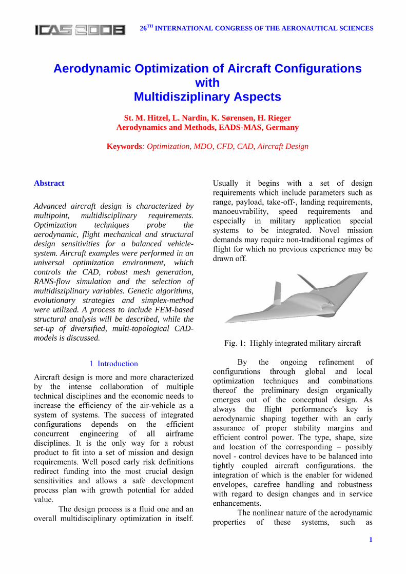
Usually it begins with a set of design requirements which include parameters such as range, payload, take-off-, landing requirements, manoeuvrability, speed requirements and especially in military application special systems to be integrated. Novel mission demands may require non-traditional regimes of flight for which no previous experience may be drawn off.
Fig. 1: Highly integrated military aircraft
By the ongoing refinement of configurations through global and local optimization techniques and combinations thereof the preliminary design organically emerges out of the conceptual design. As always the flight performance's key is aerodynamic shaping together with an early assurance of proper stability margins and efficient control power. The type, shape, size and location of the corresponding – possibly novel - control devices have to be balanced into tightly coupled aircraft configurations. the integration of which is the enabler for widened envelopes, carefree handling and robustness with regard to design changes and in service enhancements.
The nonlinear nature of the aerodynamic properties of these systems, such as
Aerodynamic Optimization of Aircraft Configurations with
Multidisziplinary Aspects
St. M. Hitzel, L. Nardin, K. Sørensen, H. Rieger Aerodynamics and Methods, EADS-MAS, Germany
Keywords: Optimization, MDO, CFD, CAD, Aircraft Design
St. M. Hitzel, L. Nardin, K. A. Sørensen, H. Rieger
2
compressibility, the complexity of controlled, uncontrolled separation as well as unsteady flow phenomena demands emphasis into high quality flow simulations early on [1]. Since almost every other design issue related to performance, flight control systems, loads, operational capabilities and other systems increasingly are mutually dependent on the reliable prediction of both flow structures and effective forces and moments high fidelity tools are required to conquer previously untried or unknown layouts [2].
High fidelity flow simulation (RANS, URANS) [3], structural analysis together with a very flexible process control system and optimization procedures, home-based in a powerful computer cluster environment open the path towards a future with higher turn-around rates for single and multidisciplinary design optimizations. Modern CAD-capabilities allow for parameterized aircraft models which can include all typical features of a design. Their object oriented layout help to integrate modern simulation techniques at an early stage.
Aero-elastic effects should be incorporated not only to allow for better weight and balance data but also to exploit aero-elastic tailoring to optimize performance and manoeuvre capabilities. Other disciplines such as electromagnetics through RCS-requirements or the inclusion of sensor-systems may impose additional conditions.
This paper describes an integrated design-optimization environment from parameterized geometry modelling, the integration of flow simulations into the optimization framework modeFrontier. Python scripts implement new optimization strategies, methods to control aerodynamic and various simplified weight estimations together with autopilot trim-functionalities into the design system. The inclusion of FEM-methods also is shown.
2 Design Optimization Process The typical design optimization cycle starts with a first set of "reasonable" geometries. The initial layout is subject to the analysis by an appropriate disciplinary method, while the
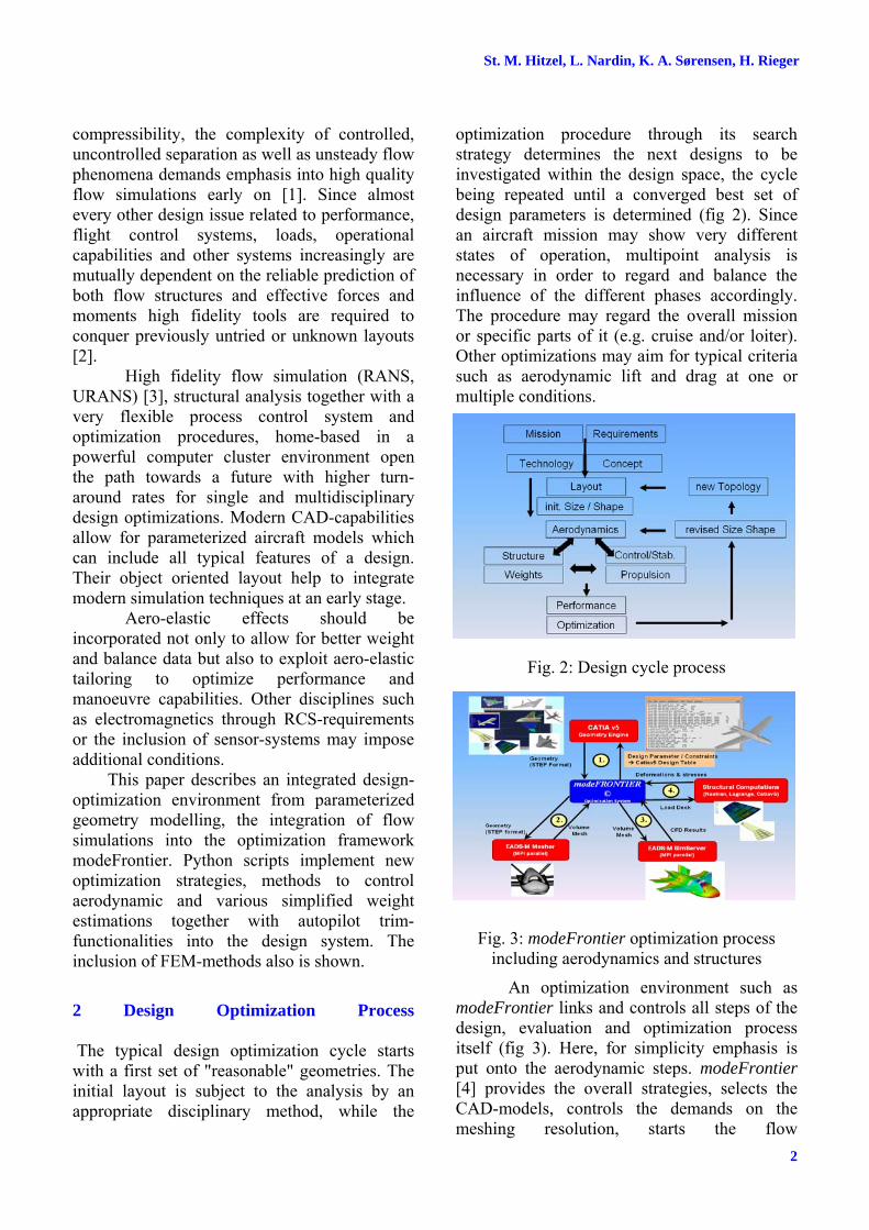
optimization procedure through its search strategy determines the next designs to be investigated within the design space, the cycle being repeated until a converged best set of design parameters is determined (fig 2). Since an aircraft mission may show very different states of operation, multipoint analysis is necessary in order to regard and balance the influence of the different phases accordingly. The procedure may regard the overall mission or specific parts of it (e.g. cruise and/or loiter). Other optimizations may aim for typical criteria such as aerodynamic lift and drag at one or multiple conditions.
Fig. 2: Design cycle process
Fig. 3: modeFrontier optimization process including aerodynamics and structures
An optimization environment such as modeFrontier links and controls all steps of the design, evaluation and optimization process itself (fig 3). Here, for simplicity emphasis is put onto the aerodynamic steps. modeFrontier [4] provides the overall strategies, selects the CAD-models, controls the demands on the meshing resolution, starts the flow

3
AERODYNAMIC OPTIMIZATION OF AIRCRAFT CONFIGURATIONSWITH MULTIDISCZPLINARY ASPECTS, ICAS 2008 – 2.11.3
simulation(s), analyses the results and evaluates the objectives. Multidisciplinary connection e.g. for weight estimations and/or by structural sizing through FEM are defined. Depending on the optimization procedure selected, regarding constraints and limits, modeFrontier then determines the next design by redefining the parameters.
3 Tools of the Optimization Environment Key to the overall process is the robustness of the tools which provide the geometries, the computational meshes, the solvers and the optimization procedures. Here a review of the properties of the geometry definition through CATIA-V5 models, the meshing of hybrid grids suited for RANS and URANS simulations is given. Also the SimServer-environment [5, 6], combining the flight-mechanical and structural analysis into the simulation is described, followed by the optimization procedures applied.
Fig. 4: Parameterized CATIA-V5 aircraft-families of similar topology
The parameterization of CATIA-V5-
models provides a variety of configurations of a common topology. Interdependent formulations may be used to change all components and parts in any detail and recombine them into a new shape. The optimization procedure reconfigures the CAD parameter-set selected according to the sensitivities of the objectives evaluated. By the means of knowledge-software cross-topology variations as shown in figure 4 are possible, however, experience advises to provide separate
models for each topology and select those by the means of the process and optimizer control since such a change also effects the optimization variables and the corresponding design sensitivities.
The more complex a geometry, the more difficult the feasiblitiy checks to avoid entanglements and non-unique geometric constellations. Depending on the CAD-methods applied complex surfaces e.g. such as wing-fuselage fairings may impose severe restrictions and negate certain models. This only can be alleviated by smart, robust CAD-design utilizing universal surface definitions and strategies. Unstructured meshing requirements demand closed surfaces and the avoidance of surface slivers, short-comings which in the future may be avoided by surface-patch independent procedures.
Fig. 5: Prismatic mesh layer
Fig. 6: Chimera approach on a configuration
The EADS-Mesher [7] program is a robust, CAD-surface adapting mesh-generator for unstructured, hybrid meshes. It is based on BREP-surfaces of CATIA-step output and has the provisions to automatically check the surface-geometry for meshing criteria. The grouping of entities into aircraft components prepares the application of boundary conditions and the extraction of local component forces and moments. Reference [7] gives more details on the tool, while figure 5 shows an example of
a b
c d

St. M. Hitzel, L. Nardin, K. A. Sørensen, H. Rieger
4
the prismatic layers of an unstructured hybrid mesh . Movable controls and trim-devices can be provided with the chimera approach (fig 6) [8].
The DLR-Tau code [3] is a second order finite volume RANS and URANS flow simulation method used here. Several one- and two equation turbulence models are available. Here Wilcox k-ω was preferred for subsonic flow cases, while LEA k-ω performed very well at transonic conditions. The code can be partitioned for any amount of computational processors in distributed memory machines. The partitioning feature makes the solver adaptable to any size of the simulation problem, while the amount of processors employed on the problem may reduce the computational time considerably.
Fig. 7: SimServer incl. motion, aeroelastic effects. Details show CAD, Meshing, post-
processing and visualisation
The SimServer [5, 6] environment (fig.
7) performs the connection of different functions of flow simulations and their interdisciplinary integration. It automatically performs all pre-processing steps such as the partitioning of the dual meshes as well as the hole cutting treatment of Chimera type meshes as well as any relative motion of a Chimera mesh. The data extraction of forces and moments to be provided for optimization objectives and flow investigations through visualisation are applied through the logical
hierarchy model. The results also are prepared for post-processing and visualisation. 4 Aerodynamic Optimization of a Combat Aircraft – Evolutionary Approach The scenario of an aerodynamic multipoint optimization for a simplified configuration without engine-nacelle (fig. 4 d) is depicted in figure 8. The reduced mission is dominated by a cruise and loiter phase, the latter of which is to be maximized. For simple stealth reasons the leading and trailing edge of the horizontal tail were made parallel to the wing leading and trailing edges. Furthermore the vertical tail and the fuselage were left unchanged, while a single "rubber" engine was assumed and not modelled in detail in the CAD. The wing and tail profiles were kept unchanged. The mission weight was assumed to be constant for the cruise and loiter phase at an average of ZFW + 0.5 full fuel weight. The design variables are wing parameters such as sweep, aspect ratio, taper ratio (inner, outer), inner wing kink span and possibly the position of the wing.
Fig. 8: Scenario for a multipoint optimization of a combat aircraft
The fuel consumption was evaluated via the thrust equals drag condition, the drag being evaluated by the flow simulation. The max rated sea level thrust as a function of elevation and Mach number is computed using data for a generic high-bypass turbofan engine. Using generic engine data the specific fuel consumption for cruise and loiter fuel is found along the same lines. With the loiter thrust required assumed to depend on the glide ratio, and the glide ratio being determined via the flow simulations, the objective loiter time becomes: ( ) ( )[ ] 1
,−−= loiterloitercruisefuelfuelloiter TTSFCWWt
5
AERODYNAMIC OPTIMIZATION OF AIRCRAFT CONFIGURATIONSWITH MULTIDISCZPLINARY ASPECTS, ICAS 2008 – 2.11.3
Both cruise and loiter had to be evaluated at trimmed conditions. For a simplified version the assumption of linear aerodynamics at low angle-of-attack, the angle-of-attack and angle-of-incidence for the horizontal tail trim-position where estimated according to Raymer [9].
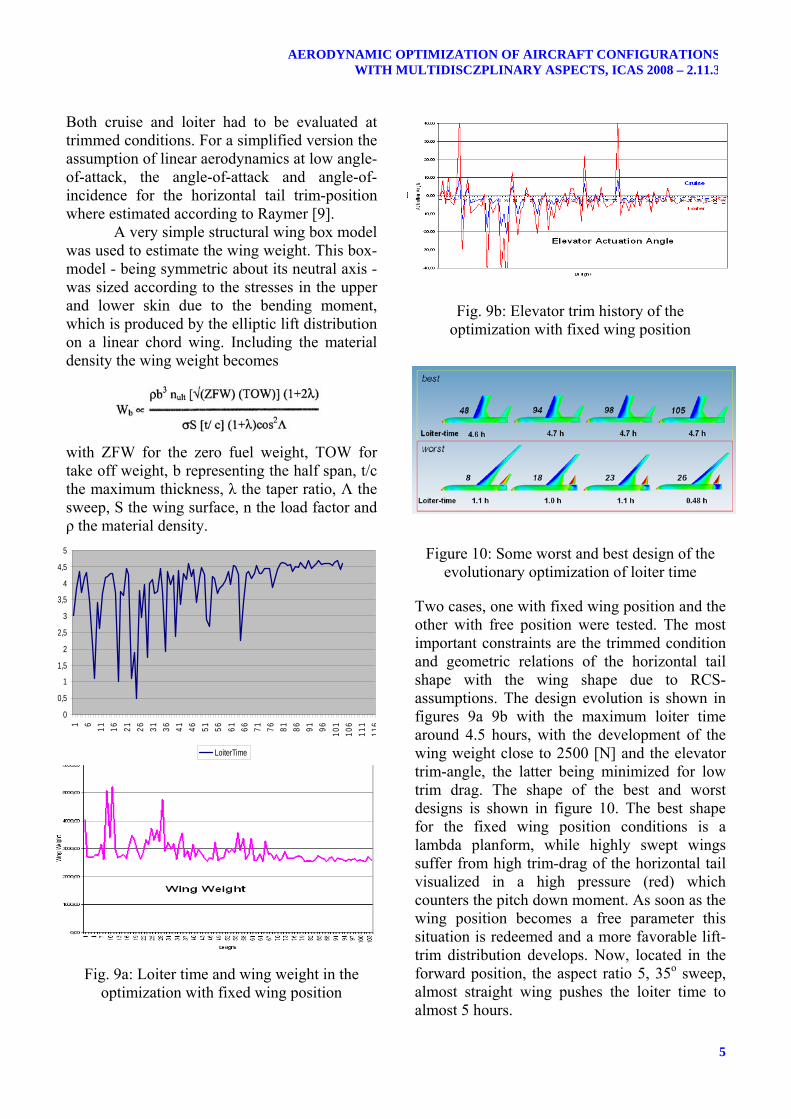
A very simple structural wing box model was used to estimate the wing weight. This box-model - being symmetric about its neutral axis - was sized according to the stresses in the upper and lower skin due to the bending moment, which is produced by the elliptic lift distribution on a linear chord wing. Including the material density the wing weight becomes with ZFW for the zero fuel weight, TOW for take off weight, b representing the half span, t/c the maximum thickness, λ the taper ratio, Λ the sweep, S the wing surface, n the load factor and ρ the material density.
Fig. 9a: Loiter time and wing weight in the optimization with fixed wing position
Fig. 9b: Elevator trim history of the optimization with fixed wing position
Figure 10: Some worst and best design of the evolutionary optimization of loiter time
Two cases, one with fixed wing position and the other with free position were tested. The most important constraints are the trimmed condition and geometric relations of the horizontal tail shape with the wing shape due to RCS-assumptions. The design evolution is shown in figures 9a 9b with the maximum loiter time around 4.5 hours, with the development of the wing weight close to 2500 [N] and the elevator trim-angle, the latter being minimized for low trim drag. The shape of the best and worst designs is shown in figure 10. The best shape for the fixed wing position conditions is a lambda planform, while highly swept wings suffer from high trim-drag of the horizontal tail visualized in a high pressure (red) which counters the pitch down moment. As soon as the wing position becomes a free parameter this situation is redeemed and a more favorable lift-trim distribution develops. Now, located in the forward position, the aspect ratio 5, 35o sweep, almost straight wing pushes the loiter time to almost 5 hours.
0
0,5
1
1,5
2
2,5
3
3,5
4
4,5
5
1 6 11 16 21 26 31 36 41 46 51 56 61 66 71 76 81 86 91 96 101
106
111
116
LoiterTime

St. M. Hitzel, L. Nardin, K. A. Sørensen, H. Rieger
6
Figure 11: Best design with free wing position (inset best wing with fixed wing position)
5 Optimization of an Aircraft Wing – SIMPLEX Approach The SIMPLEX-methodology was used for the optimization of an isolated wing, the very best of which to be integrated into a full aircraft design optimization later on. The effect of different design conditions was checked together with gathering some experience on the impact of different structural topologies. As before, the span, the leading edge sweep, the tip and mid chord as well as the wing twist were selected as independent variables. An airfoil optmization was added by the resultant shape of a mix of 4 characteristic profiles, its camber shape and profile thickness (fig. 12).
Fig. 12: Airfoil shapes and parametric camber The objective of the wing optimization was maximum range for a given aircraft weight, payload and engine. Two different
configurations demanding a light condition CL = 0.23 and a heavy condition CL = 0.5 at Mach 0.77. Upper and lower limits of the pitching moment were used as additional constraints.
Fig. 13: Wing pressure distribution with different design conditions
and wing box models
Figure 13 a and b show optimized maximum range configurations and their surface pressure distribution of the tow different load cases. As expected the lower lift requirements reduce the aspect ratio to minimize the wing weight by a short span and rather thick and long root chord geometries.
The higher lift, straight wing box case is dominated by induced aerodynamic drag which is reduced by an increase of the aspect ratio, which overrides the span-related increase in weight. Figure 14 develops the optimization history of range for the SIMPLEX approach for the low loading, figure 15 the high wing loading case.
Fig. 14: Development of range of a SIMPLEX-optimizations for two wings at Mach = 0.77
a b

7
AERODYNAMIC OPTIMIZATION OF AIRCRAFT CONFIGURATIONSWITH MULTIDISCZPLINARY ASPECTS, ICAS 2008 – 2.11.3
Fig. 15: Range for a SIMPLEX-optimization of a CL = 0.5 wing at Mach = 0.77
The higher load CL = 0.5 design shows a distinct development of twist to reduce drag by thriving for a more elliptic lift distribution. The best design of the optimizations shown here developed -1.75o of twist, while the span still increases (fig. 16). Further design cycles would increase this tendency. The low lift cases showed a maximum twist of -0.6o only.
Fig. 16: Development of span and twist for the CL = 0.5 wing maximum range design
at Mach = 0.77
6 Optimization of a combat aircraft – MOGA genetic approach For a full aircraft optimization an isolated wing was developed along the same lines as above. To allow for a high aerodynamic efficiency via good L/D values, α was chosen as an additional parameter, the objective range was evaluated via the Breguet-equation. The optimum angle of
attack of the isolated wing (fig. 17) was applied as its angle of incidence in the complete aircraft configuration(fig. 18). The wing position along the center fuselage became a configurational parameter and was allowed to vary more than 700 mm.
Fig. 17: Wing optimized for full aircraft optimization
Fig. 18: Full aircraft configuration The location of the engine installation and the fuselage center section shape became additional configurational design parameters, while the incidence of the horizontal tail as well as the angle-of-attack had to provide steady longitudinal flight conditions. The engine position could move in between 62% and 75% of the fuselage length. The upper part of the two mid fuselage cross sections could be modified in between 350 mm to 650 mm in to accommodate more fuel volume.
Here, an autopilot functionality which guarantees level flight (CL = weight, Cm = 0.0) operated on the basis of full RANS-simulations was employed. Each autopilot trim requires at least three evaluations to obtain level flight angle-of-attack and elevator trim-angle. The

St. M. Hitzel, L. Nardin, K. A. Sørensen, H. Rieger
8
horizontal tail trim- or autopilot evaluation-position was introduced via a chimera-mesh method [8]. A typical autopilot trim is shown in figure 19 by the convergence of lift CL and pitch Cm. The interruptions indicate the evaluations for derivatives and the final the level flight conditions. Fig.19: Autopilot for level flight trim conditions
Fig. 20: Optimization of range by the genetic algorithm MOGA
By nature genetic algorithms do not show a development of objectives and parameters such as gradient based or evolutionary methods. The recombination of parts of the most fit designs produces a random set of designs (fig. 2), where
the upper-most bound indicate the best designs. Figure 20's blue and green stars mark the best and the worst design respectively.
Fig. 21: Best and worst aircraft design at Mach = 0.77
A comparison of the worst and best designs surface pressure distribution is shown in figure 21. The forward position of the engine has multiple benefits for the design. Firstly it avoids the shock prone velocities in between the engine and the vertical tails and secondly it pushes the engine's centre of gravity closer to the overall c.g., improving the trim situation. Together with a more streamlined fuselage it also reduces the recompression effects ahead of the engine. The fuller fuselage provides some extra fuel and shows a much more favorable interference in between wing and fuselage. This allows for a much lower angle of attack which reduces the induced drag. An inspection of the elevator incidence shows a much reduced angle of incidence thereby reducing the trim-drag. 7 Aero-Structural Wing Optimization Based on Parameterized Structural Models To replace the simple wing weight estimation, provisions were made to model a realistic parameterized structure via CATIA-V5 (fig. 22a). Its parameters control the amount of ribs and the positions of the front and rear wing spars together with structural thickness distributions.
This geometry is automatically meshed into a shell element FEM-model (fig. 22b). Also the aerodynamic pressure is mapped onto this
best worst
best worst

9
AERODYNAMIC OPTIMIZATION OF AIRCRAFT CONFIGURATIONSWITH MULTIDISCZPLINARY ASPECTS, ICAS 2008 – 2.11.3
FEM-model (fig 23). Together with the gravity loads and/or other inertia loads and external forces (e.g. from engines) a NASTRAN-deck is provided automatically, which then can be used to size the local thickness of the wing structure according to suitable criteria such as stress limitations (fig 24). The evaluation of the wing structure weight then can be fed into the overall optimization procedure.
Fig. 22: (a) CAD-Geometry, (b) FEM-model of a structural model of a wing
Fig. 23: Load distribution of a structural wing model for NASTRAN
Fig. 24: van Mises stress distribution before sizing
The integration of the FEM-based
weight evaluation into the overall optimization process is shown in figure 25.
Fig. 26: Optimization incl. structural weight via FEM
Some results of the sizing process for
different amounts of structural ribs, the FEM-resolution and the location of the spars can be found in figure 26, which depicts the element thickness distributions. The stress paths can be distinguished by a relatively high value for the local element thickness. In figure 26a a rather thick skin indicates that the front spar's location is far from optimal. A subsequent relocation bettered this problem in figure 26b, c and d. and the corresponding wing weights are reduced from 1660 [N] in version a, to 1450 [N] in version b. In principle the thickness distribution has been bettered, however, some disturbances are still visible in the mid wing region.
a
b

St. M. Hitzel, L. Nardin, K. A. Sørensen, H. Rieger
10
In figure 26c the FEM-mesh was refined by a factor of 2 in all directions and the high stress respectively thickess in the mid wing region has disappeared to be concentrated along the front spar. Also disturbances are now visible mainly at the trailing edges. This could be explained by some insufficient FEM modelling in that area.
A drastic increase in ribs for version 26d resulted in a very much improved situation although the density of the FEM-knots was not increased relative to version 26b. The maximum element thickness is concentrated along the spars and the former hot spots are almost gone. Correspondingly the weight of this wing structure has improved down to 1350 [N].
Closer inspection reveals further room for improvements in the direction of the wing ribs. Naturally swept wings develop stress pathes normal to the wing's elastic axis. Repositioning of the ribs along the stress paths could be achieved by additional parameterization in the CAD-model to account for flexibility in the structural topology not being performed in this pathfinder process.
Figure 26: FEM-Element thickness distribution for different structural layouts and resolution
8 Summary A high fidelity simulation and optimization process for aerodynamically driven problems an aircraft design cycle has been presented. The paper demonstrates the capability to setup complex optimization processes involving advanced flow simulation tools. Mission driven aircraft shaping problems including plan form, wing and profile design issues were undertaken. Also taken into account are aircraft structural weight and engine performance issues. It furthermore showed the development and utilization of parameterized CAD- and structural models within the optimization process loop. This process is open for the integration of flight dynamical as well as structural multidisciplinary considerations. The multidiscplinary capabilities are provided by an integrated environment and possible add ons through Python scripting. Evidence for a quick set-up of an optimization problem within the modeFRONTIER optimization system and process control environment has been shown. The integration of successful structural sizing optimization of the wing structure using parameterized FEM-models out of CATIA-v5 was also included. Most of the developments available will be used within an operational context after necessary adaptations. In summary the capabilities and the competitiveness within flight physics has gained a lot from the EU-MEGADESIGN project.
References [1] Rieger, H., Leicher, S., Fritz, W., Hitzel, S.,
Fornasier, L, Tremel, U., v.d. Weide, E., „Perspektiven der aerodynamischen Simulation in der Kampfflugzeugentwicklung“ DGLR-2002-014, DGLR-Jahrestagung, Stuttgart, 2002.
[2] Rieger, H. “Experiences in Aerodynamic Shape Optimization at EADS-Military Aircraft Systems”, 6th Int. Congress on Industrial and Applied Mathematics, Zurich, 16.-20. July 2007
[3] Gerold T, Friedrich O, Evans J, Galle M. Calculation of Complex Three-Dimensional Configurations Employing the DLR-Tau Code, AIAA 97-0167, 1997
[4] modeFrontier – A multi-Objective Optimization and Design Environment, http://www.esteco.com
a b
c d

11
AERODYNAMIC OPTIMIZATION OF AIRCRAFT CONFIGURATIONSWITH MULTIDISCZPLINARY ASPECTS, ICAS 2008 – 2.11.3
[5] Tremel U, Deister F, Sørensen K, Rieger H, Weatherhill N. The SimServer – A Parallel Multidisciplinary Simulation Environment, DGLR-2003-099, München, Germany 2003
[6] Tremel U, Hitzel St, Sørensen K, Weatherhill N. JDAM Store Separation from an F/A-18C – An Application of the Multidisciplinary SimServer System, AIAA 23rd Applied Aerodynamics Conference 2005, Toronto, Canada
[7] Tremel U. Parallel Unstructured Adaptive Remeshing for Moving Boundary Problems, EADS-MT632-S-PUB-0649, April 2005, EADS-MAS
[8] Sørensen K, Tremel U, Rieger H, Hitzel St. Simulation of a Manoeuvering Fighter Aircraft with the Unstructured Chimera Approach, AIAA – 2007 -123, Reno, NV, 2007
[9] Raymer D, Aircraft Design: A Conceptual Approach, AIAA Education Series, 1989
Copyright Statement The authors confirm that they, and/or their company or institution, hold copyright on all of the original material included in their paper. They also confirm they have obtained permission, from the copyright holder of any third party material included in their paper, to publish it as part of their paper. The authors grant full permission for the publication and distribution of their paper as part of the ICAS2008 proceedings or as individual off-prints from the proceedings.