Embed Size (px)
Citation preview

International Journal of Innovative Research in Advanced Engineering (IJIRAE) ISSN: 2349-2163 Issue 04, Volume 4 (April 2017) (SPECIAL ISSUE) www.ijirae.com
____________________________________________________________________________________________________ IJIRAE: Impact Factor Value – SJIF: Innospace, Morocco (2016): 3.916 | PIF: 2.469 | Jour Info: 4.085 |
ISRAJIF (2016): 3.715 | Indexcopernicus: (ICV 2015): 47.91 IJIRAE © 2014- 17, All Rights Reserved Page -86
Aerodynamic analysis and optimization of wind deflector in a
Commercial load transport vehicle.
Ramesh D Ka , Rajesha Rb , Snehashree K Bb , Shashanka A Bhatb ,Manogna N Rb a Associate Professor , b UG Scholar
Department of Mechanical Engineering, University Visvesvaraya College of Engineering, K R Circle, Bangalore 560001, Karnataka, India
Abstract: In the field of commercial goods transport, trucks have an important place. One of the main problems faced by truck manufacturers is the Air resistance associated with the highway running. Since trucks have a large frontal area and the presence of a trailer also leads to the truck experiencing significant resistance which has to be overcome. This can be reduced through the use of wind deflectors. A well-designed wind deflector can reduce wind resistance to a certain extent. Optimizing the angle of the wind deflector also causes reduced drag force acting on the vehicle, thereby reducing the fuel intake. Here the initial drag of 2050 N is reduced to 1688.453 N using a 1.75 m wind deflector at 45 degree angle resulting in the reduction of drag by 17.6%.
Keywords: Aerodynamic Drag, Wind Deflector, Truck Aerodynamics
I. INTRODUCTION
To save energy and to protect the global environment, fuel consumption reduction is a primary concern of automotive development. In vehicle body development, reduction of drag is essential for improving fuel consumption and driving performance [1]. Aerodynamic drag accounts for about 50% of the total energy delivered to the wheels of a vehicle traveling at a constant speed of about 88 km/h (55 mph) on a level road. This increases to about 75% at typical highway speeds of 110 km/h (70 mph) and is 65% even for loaded class-8 tractor trailer trucks. This is because the drag force FD is proportional to CD.V2, where the coefficient of drag CD remains approximately constant as the velocity of the air relative to the vehicle (V) increases [5, 6]. For vehicles, such as long-distance tractor trailer trucks which spend more time traveling at constant speed on highways, even a modest reduction in CD can have a measurable impact on fuel consumption. The majority of the shaft power derived from this fuel is used to overcome aerodynamic drag at highway speeds, while the remaining portion is dissipated through tire rolling resistance and drivetrain friction [5]. Although the entire vehicle was investigated for various avenues of reducing drag, the primary focus of these efforts was the aerodynamics of the tractor and the front of the trailer [5].
Fig-1: The aerodynamic fluid flow over a stock truck
For heavy vehicles such as tractor-trailer combinations and buses, pressure drag is the dominant component due to the large surfaces facing the main flow direction and due to the large wake resulting from the bluntness of the back end of such vehicles [7]. Although friction drag occurs along the external surfaces of heavy vehicles, particularly along the sides and top of buses and trailers, its contribution to overall drag is small (10% or less) and is not a strong candidate for drag-reduction technologies[7].
GENERAL FLOW PATTERN AROUND TRUCK BODY Aerodynamic drag, also called wind resistance is a retarding force exerted on a vehicle by the air through which it moves. As a truck moves forward it breaks up the flow of air, creating an area of low pressure behind the body or trailer (the wake) [8]. The high- pressure air surrounding the wake then moves into the low pressure area, exerting a force that pulls the vehicle backwards. Low pressure areas created in the gap between the tractor and the trailer, and underneath the truck, similarly contribute to aerodynamic drag.
International Journal of Innovative Research in Advanced Engineering (IJIRAE) ISSN: 2349-2163 Issue 04, Volume 4 (April 2017) (SPECIAL ISSUE) www.ijirae.com
____________________________________________________________________________________________________ IJIRAE: Impact Factor Value – SJIF: Innospace, Morocco (2016): 3.916 | PIF: 2.469 | Jour Info: 4.085 |
ISRAJIF (2016): 3.715 | Indexcopernicus: (ICV 2015): 47.91 IJIRAE © 2014- 17, All Rights Reserved Page -87
Fig-2: Formation of vortices in the gap between the tractor and trailer
The amount of energy required to overcome aerodynamic drag is affected by the effective frontal surface area of the vehicle, the shape of the vehicle and the speed at which the vehicle is travelling [7, 8]. Aerodynamics of tractor trailer is affected by the shape of the tractor cab, the transition between the back of the cab and the front of the trailer, the gap distance between the tractor and trailer, the underbody of the truck, and the rear edge of the trailer. Principles which reduce the effort of aerodynamic drag are : the cab should be shaped as aerodynamically as possible, and there should be a smooth transition between the top of the cab and the top of the trailer (either through height matching or connections that create a smooth line between the two),the gap distance between the tractor and trailer should be minimized, by positioning the two as close together as possible or blocking the air flow into the gap, air should be blocked from travelling under the truck, or the underbody of the truck should be made as aerodynamic (smooth) as possible, the rear end of the trailer should be rounded or extended in a way that creates a more aerodynamic shape.
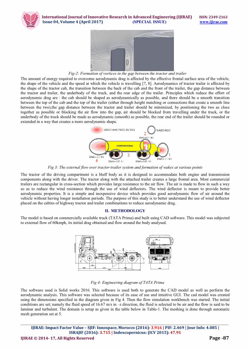
Fig 3: The external flow over tractor-trailer system and formation of wakes at various points
The tractor of the driving compartment is a bluff body as it is designed to accommodate both engine and transmission components along with the driver. The tractor along with the attached trailer creates a large frontal area. Most commercial trailers are rectangular in cross-section which provides large resistance to the air flow. The air is made to flow in such a way so as to reduce the wind resistance through the use of wind deflectors. The wind deflector is meant to provide better aerodynamic properties. It is a simple and inexpensive device which provides good aerodynamic flow of air around the vehicle without having longer installation periods. The purpose of this study is to better understand the use of wind deflector placed on the cabins of highway tractor and trailer combinations to reduce aerodynamic drag.
II. METHODOLOGY
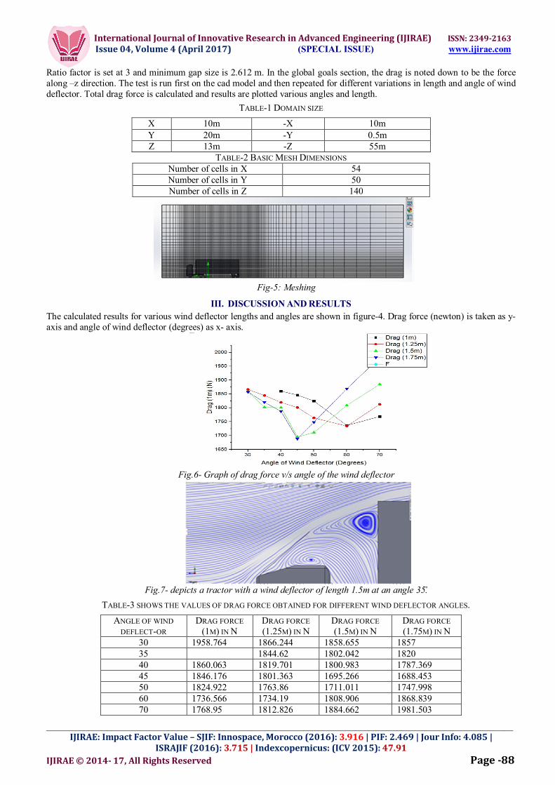
The model is based on commercially available truck (TATA Prima) and built using CAD software. This model was subjected to external flow of 60kmph, its initial drag obtained and flow around the body analysed.
Fig 4: Engineering diagram of TATA Prima
The software used is Solid works 2016. This software is used both to generate the CAD model as well as perform the aerodynamic analysis. This software was selected because of its ease of use and intuitive GUI. The cad model was created using the dimensions specified in the diagram given in Fig 4. Then the flow simulation workbench was started. The initial conditions are set; namely the fluid speed of 16.67 m/s in –z direction, the fluid is selected to be air and the flow is said to be laminar and turbulent. The domain is setup as given in the table below in Table-1. The meshing is done through automatic mesh generation set at 5.
International Journal of Innovative Research in Advanced Engineering (IJIRAE) ISSN: 2349-2163 Issue 04, Volume 4 (April 2017) (SPECIAL ISSUE) www.ijirae.com
____________________________________________________________________________________________________ IJIRAE: Impact Factor Value – SJIF: Innospace, Morocco (2016): 3.916 | PIF: 2.469 | Jour Info: 4.085 |
ISRAJIF (2016): 3.715 | Indexcopernicus: (ICV 2015): 47.91 IJIRAE © 2014- 17, All Rights Reserved Page -88
Ratio factor is set at 3 and minimum gap size is 2.612 m. In the global goals section, the drag is noted down to be the force along –z direction. The test is run first on the cad model and then repeated for different variations in length and angle of wind deflector. Total drag force is calculated and results are plotted various angles and length.
TABLE-1 DOMAIN SIZE
X 10m -X 10m Y 20m -Y 0.5m Z 13m -Z 55m
TABLE-2 BASIC MESH DIMENSIONS Number of cells in X 54 Number of cells in Y 50 Number of cells in Z 140
Fig-5: Meshing
III. DISCUSSION AND RESULTS
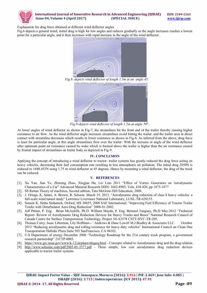
The calculated results for various wind deflector lengths and angles are shown in figure-4. Drag force (newton) is taken as y-axis and angle of wind deflector (degrees) as x- axis.
Fig.6- Graph of drag force v/s angle of the wind deflector
Fig.7- depicts a tractor with a wind deflector of length 1.5m at an angle 35.̊
TABLE-3 SHOWS THE VALUES OF DRAG FORCE OBTAINED FOR DIFFERENT WIND DEFLECTOR ANGLES.
ANGLE OF WIND DEFLECT-OR
DRAG FORCE (1M) IN N
DRAG FORCE (1.25M) IN N
DRAG FORCE (1.5M) IN N
DRAG FORCE (1.75M) IN N
30 1958.764 1866.244 1858.655 1857 35 1844.62 1802.042 1820 40 1860.063 1819.701 1800.983 1787.369 45 1846.176 1801.363 1695.266 1688.453 50 1824.922 1763.86 1711.011 1747.998 60 1736.566 1734.19 1808.906 1868.839 70 1768.95 1812.826 1884.662 1981.503
International Journal of Innovative Research in Advanced Engineering (IJIRAE) ISSN: 2349-2163 Issue 04, Volume 4 (April 2017) (SPECIAL ISSUE) www.ijirae.com
____________________________________________________________________________________________________ IJIRAE: Impact Factor Value – SJIF: Innospace, Morocco (2016): 3.916 | PIF: 2.469 | Jour Info: 4.085 |
ISRAJIF (2016): 3.715 | Indexcopernicus: (ICV 2015): 47.91 IJIRAE © 2014- 17, All Rights Reserved Page -89
Explanation for drag force obtained at different wind deflector angles Fig.6 depicts a general trend, initial drag is high for low angles and reduces gradually as the angle increases reaches a lowest point for a particular angle, and it then increases with rapid increase in the angle of the wind deflector.
Fig.8- depicts wind deflector of length 1.5m at an angle 45.̊
Fig.9-depicts wind deflector of length 1.5m at angle 50̊̊◌֯.
At lower angles of wind deflector as shown in Fig-7, the streamlines hit the front end of the trailer thereby causing higher resistance to air flow. As the wind deflector angle increases streamlines avoid hitting the trailer, and the trailer area in direct contact with streamline decreases which results in lower resistance as shown in Fig-8. As inferred from the above, drag force is least for particular angle, at this angle streamlines flow over the trailer. With the increase in angle of the wind deflector after optimum point air resistance caused by wake which is formed above the trailer is higher than the air resistance caused by frontal impact of streamlines on trailer body as depicted in Fig-9.
IV. CONCLUSION
Applying the concept of introducing a wind deflector to tractor- trailer systems has greatly reduced the drag force acting on heavy vehicles, decreasing their fuel consumption rate resulting in less atmospheric air pollution. The initial drag 2050N is reduced to 1688.453N using 1.75 m wind deflector at 45 degrees. Hence by mounting a wind deflector, the drag of the truck can be reduced.
V. REFERENCES
[1]. Xu Yan, Jian Ye, Zhiming Zhao, Xingjun Hu, Lei Liao 2011 “Effect of Vortex Generators on Aerodynamic Characteristics of a Car” Advanced Material Research ISSN: 1662-8985, Vols. 418-420, pp 1873-1877
[2]. SS Rattan Theory of machines, Second edition, Tata McGraw-Hill Education, 2008. [3]. J. Ortega, K. Salari, A. Brown, R. Schoon. March 19, 2013, “Aerodynamic drag reduction of class 8 heavy vehicles: a
full-scale wind tunnel study” Lawrence Livermore National Laboratory, LLNL-TR-628153. [4]. Sumon K. Sinha Sinhatech, Oxford, MS 38655, 2008 SAE International; “Improving Fuel Efficiency of Tractor Trailer
Trucks with Deturbulator Aero-Drag Reduction” 2008-01-2602. [5]. Jeff Patten, P. Eng. Brian McAuliffe, Ph.D. William Mayda, P. Eng. Bernard Tanguay, Ph.D May-2012 “Technical
Report- Review of Aerodynamic Drag Reduction Devices for Heavy Trucks and Buses” National Research Council of Canada Centre for Surface Transportation Technology, Project 54-A3578 CSTT-HVC-TR-205.
[6]. Thomas Curry, Isaac Liberman, Lily Hoffman- Andrews & Dane Lowell M.J.Bradley & Associates LLC. October 2012 “Reducing aerodynamic drag and rolling resistance for heavy duty vehicles” International Council on Clean One Transportation Hallidie Plaza Suite 503 SanFrancisco, CA 94102.
[7]. U.S Department of energy December 2006 “Technology Roadmap for the 21st century truck program, a government research partnership” 21CTP-0003.
[8]. https://www.grc.nasa.gov/www/k-12/airplane/drageq.html - Concepts related to Aerodynamic drag and the drag relation. [9]. http://www.solusinc.com/pdf/2003-01-3377.pdf - Three simple, low cost aerodynamic drag reduction devices
applicable to tractor trailer systems


![[ Rattan Agency]](https://img.dokumen.tips/doc/110x75/568144a1550346895db160a5/-rattan-agency.jpg)
