Embed Size (px)
Citation preview
Bellevue Ambulatory Care Pavilion New York, NY
AE 481 - Thesis Proposal
Mechanical System Redesign
Prepared for: Dr. Jelena Srebric, PhD Department of Architectural Engineering The Pennsylvania State University
Prepared by: David Sivin Mechanical Option December 12, 2008
Bellevue Ambulatory Care Pavilion – 462 1st Avenue – New York, NY 10016
1 AE 481 Thesis Proposal – Mechanical System Redesign
TABLE OF CONTENTS
EXECUTIVE SUMMARY* 2
BUILDING OVERVIEW 3
MECHANICAL DESIGN OBJECTIVES AND REQUIREMENTS 4
MECHANICAL SYSTEM OVERVIEW 5
MECHANICAL SYSTEM CRITIQUE 7
MECHANICAL SYSTEM REDESIGN 8
PROPOSAL BREADTH TOPICS 11
PROJECT METHODS: INTEGRATION AND COORDINATION* 12
SPRING 2009 PROPOSED SCHEDULE 13
REFERENCES 18
*Includes Description of Incorporated Material from AE 557 – Central Cooling Systems

Bellevue Ambulatory Care Pavilion – 462 1st Avenue – New York, NY 10016
2 AE 481 Thesis Proposal – Mechanical System Redesign
EXECUTIVE SUMMARY
The Bellevue Ambulatory Care Pavilion serves as an outpatient care facility and an addition to
the Bellevue Hospital Center in New York City. It is a 5-story, 207,000 ft2 building located between 1st
Avenue and the FDR Drive highway. The building’s mechanical systems, both heating and cooling, are
not local; the heating system taps into a main municipal high pressure steam line and the cooling system
taps into an existing chiller plant in the older Bellevue Hospital Center.
This proposal will outline the topics, methods and timeline that will be approached for the
mechanical redesign and two breadth topics.
For the mechanical redesign, the implementation of a local absorption chiller plant will be
assessed. The new chiller plant will include steam-fired absorption chillers and a new cooling tower
structure. An energy model in Trane TRACE 700 will help determine the monthly energy and cost
profiles of this new chiller plant. To fulfill the M.A.E. requirements, parametric studies through EES will
help determine the optimum energy usage cycles for these chillers and their cooling towers. In AE 557,
assignments which dealt with parametric studies for coupled chillers and cooling towers relate to this
proposed redesign. In addition to the chiller plant, the implementation of a local condenser boiler plant
will be assessed. The energy model in Trane TRACE 700 will help yield monthly energy and cost profiles.
In addition to the mechanical redesign, a structural and architectural breath will be developed. The
structural breadth will involve redesigning a structural system which will sufficiently support the newly
installed mechanical systems. Simulations through RAM will yield an acceptable layout. The
architectural breadth will involve a reworking of the main entrance doors and ramps, as to minimize air
infiltration and exfiltration. A computational fluid dynamic analysis with Fluent or other applicable
software will help in this analysis.
After all studies and simulations have been performed, a comparative analysis will determine
whether the pursued technologies provide significant energy and cost savings. Hopefully, the locality of
these plants results in more opportunities for the end-users of the mechanical systems to optimize
energy consumption.
A scheduled layout of timelines and milestones shows the anticipated sequence of work for the
Spring 2009 semester.

Bellevue Ambulatory Care Pavilion – 462 1st Avenue – New York, NY 10016
3 AE 481 Thesis Proposal – Mechanical System Redesign
BUILDING OVERVIEW
The Bellevue Ambulatory Care Pavilion serves as an addition to the Bellevue Medical Center,
America’s oldest public hospital, which originally opened in 1736 and last had renovations in 1973. The
building is located on 462 1st Avenue between 26th and 28th Street in Manhattan, NY, as seen in Figure 1.
The recently constructed five story pavilion is connected to the old medical center by a curtain
wall encased atrium that extends up roughly 90 feet. From inside this atrium, you can see how the
façade of the old hospital center connects to the modern care pavilion. Rather than two eras of
architecture clashing with each other, the two structures fit well together to make a remarkable
aesthetic feature. Since it shares functions with the older parts of the Medical Center, some of its
energy systems and sources root themselves in the systems of the older building. Of the 215,509 ft2 of
gross floor area, only 213,161 ft2 qualifies as rentable space. The basement and penthouse serve only
mechanical, electrical and plumbing equipment and have no regularly occupied spaces. In addition,
21.34% of the rentable floor space is lost due to extra mechanical equipment floor space and vertical
mechanical shaft area.
Figure 1: Site View of the Bellevue Ambulatory Care Pavilion

Bellevue Ambulatory Care Pavilion – 462 1st Avenue – New York, NY 10016
4 AE 481 Thesis Proposal – Mechanical System Redesign
MECHANICAL DESIGN OBJECTIVES AND REQUIREMENTS
From the preliminary phases of design, the project teams did not have very unique or visionary
objectives for this building. However, a few design requirements do apply. The new ambulatory care
pavilion needed to maintain the façade of the old building in the new atrium with the exception of
removing window AC units and renovating the ground floor windows to accommodate the atrium
smoke purge system. Also, from a mechanical standpoint, the pavilion needed to share whatever
facilities it could from the old medical building. The motives behind this decision dealt with avoiding
hiring additional on-site monitoring personnel. Finally, all project teams based their work on complying
with ASHRAE Standards 62.1-2007 and 90.1-2007.

Bellevue Ambulatory Care Pavilion – 462 1st Avenue – New York, NY 10016
5 AE 481 Thesis Proposal – Mechanical System Redesign
MECHANICAL SYSTEMS OVERVIEW
Condenser Water System
For heat rejection purposes, 8 open single-cell cooling towers each utilize 3,500 gpm of
condenser water from the chiller plant. This cooling tower module is located on the roof of the old
medical building. Like the chiller plant, this cooling tower module is located off-site, on the roof of the
old medical building. Each cooling tower fan has an attached variable frequency drive (VFD) to stage the
speeds from zero to half, half to zero and so forth. Whenever a cooling tower nears its capacity, another
cooling tower starts up and runs at 90% capacity for 5 minutes. After which, all running cooling towers
run at equal capacity. The cooling towers supply 85˚F condenser water to the operating 2500 chillers on
the 13th floor of the old medical building. Flow meters at the cooling tower outlet and control valves at
the chiller inlet determine how many of the four 7,000 gpm constant speed condenser water pumps will
run. A fraction of the condenser water return passes through a sodium chromate dissolving tank
package to filter out any precipitates. While it is not shown on the corresponding schematic, the cooling
towers can also operate under water-side free cooling mode. If the outdoor dry bulb temperature ever
falls below 45˚F, bypass valves fully open and direct 42˚F condenser water to the load.
Chilled Water System
For cooling purposes, three electric powered and one steam powered chillers each produce a
maximum capacity of 2,500 gpm of 41˚F chilled water. This chiller plant is located on the 13th
mechanical floor of the old medical building. While this chiller plant can produce a maximum of 10,000
gpm of chilled water, the Bellevue Ambulatory Care Pavilion only receives a maximum of 1,920 gpm of
this chilled water. Four 4,140 gpm pumps equipped with VFD’s convey the chilled water to the load for
both the medical building and the ambulatory care pavilion. A pressure differential butterfly valve
regulates the amount of chilled water supplied to the old medical building. In addition, two 960 gpm
chilled water booster pumps equipped with VFD’s isolate 1,920 gpm of chilled water to the ambulatory
care pavilion only. Flow meters at the evaporator outlet and control valves at air handling unit coil inlets
help determine the speed of these variable speed pumps. After passing through these booster pumps,
the chilled water runs to all of the air handling units in Bellevue Ambulatory Care Pavilion, with the
exception of AHU-11.
Bellevue Ambulatory Care Pavilion – 462 1st Avenue – New York, NY 10016
6 AE 481 Thesis Proposal – Mechanical System Redesign
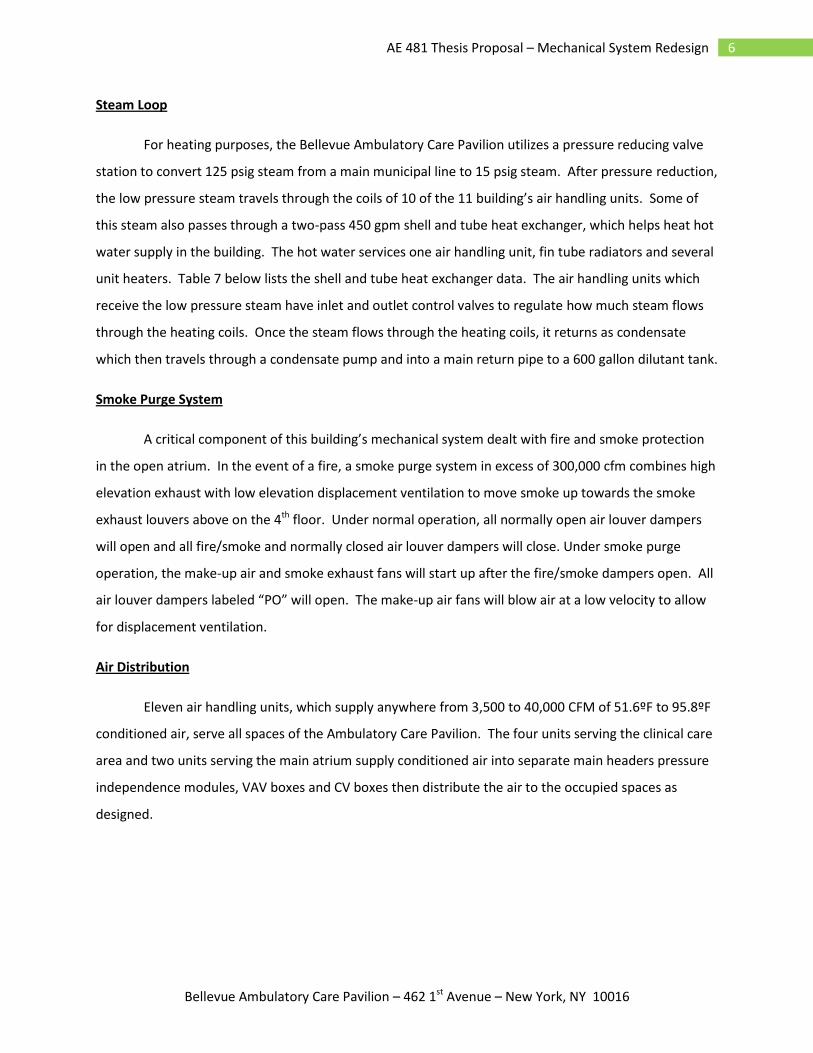
Steam Loop
For heating purposes, the Bellevue Ambulatory Care Pavilion utilizes a pressure reducing valve
station to convert 125 psig steam from a main municipal line to 15 psig steam. After pressure reduction,
the low pressure steam travels through the coils of 10 of the 11 building’s air handling units. Some of
this steam also passes through a two-pass 450 gpm shell and tube heat exchanger, which helps heat hot
water supply in the building. The hot water services one air handling unit, fin tube radiators and several
unit heaters. Table 7 below lists the shell and tube heat exchanger data. The air handling units which
receive the low pressure steam have inlet and outlet control valves to regulate how much steam flows
through the heating coils. Once the steam flows through the heating coils, it returns as condensate
which then travels through a condensate pump and into a main return pipe to a 600 gallon dilutant tank.
Smoke Purge System
A critical component of this building’s mechanical system dealt with fire and smoke protection
in the open atrium. In the event of a fire, a smoke purge system in excess of 300,000 cfm combines high
elevation exhaust with low elevation displacement ventilation to move smoke up towards the smoke
exhaust louvers above on the 4th floor. Under normal operation, all normally open air louver dampers
will open and all fire/smoke and normally closed air louver dampers will close. Under smoke purge
operation, the make-up air and smoke exhaust fans will start up after the fire/smoke dampers open. All
air louver dampers labeled “PO” will open. The make-up air fans will blow air at a low velocity to allow
for displacement ventilation.
Air Distribution
Eleven air handling units, which supply anywhere from 3,500 to 40,000 CFM of 51.6ºF to 95.8ºF
conditioned air, serve all spaces of the Ambulatory Care Pavilion. The four units serving the clinical care
area and two units serving the main atrium supply conditioned air into separate main headers pressure
independence modules, VAV boxes and CV boxes then distribute the air to the occupied spaces as
designed.

Bellevue Ambulatory Care Pavilion – 462 1st Avenue – New York, NY 10016
7 AE 481 Thesis Proposal – Mechanical System Redesign
MECHANICAL SYSTEM CRITIQUE
From a performance standpoint, this building’s mechanical systems do not appear to have
significant problems. Besides for a rupture of one of the cooling tower VFD’s support seat, the
mechanical system has an exceptional history of operation. However, a few points outside of the
mechanical scope come to mind. From the beginning of design, the building owners stressed that the
new ambulatory care pavilion tap its chilled water and steam from remote plants. While this greatly
reduced first cost, it disabled the ambulatory care pavilion to have significant control over its energy
plants. A local chiller or boiler plant came up as a suggestion, but building owners quickly rejected the
idea. A cost analysis which hopefully proves that local plants would save money could benefit this
building. Also, the architecture of the main lobby entrance presents a dilemma. Even though the main
entrance has revolving doors to help keep conditioned air indoors, ADA regulations require swing doors.
The swing doors have motion sensors to keep the doors open for 5 seconds at a time. People entering
and leaving this lobby tend to leave through the regularly open swing doors, which allows for excess air
infiltration or exfiltration. Temperature sensors over-compensate for this loss and demand more
cooling/heating from the air handling units. Perhaps a tweak in the layout and occupant circulation
paths can alleviate this energy loss problem.

Bellevue Ambulatory Care Pavilion – 462 1st Avenue – New York, NY 10016
8 AE 481 Thesis Proposal – Mechanical System Redesign
MECHANICAL SYSTEM REDESIGN
As mentioned in the system critique, this building’s mechanical systems do not have a bad
operating history or performance problems. However, opportunities exist for energy optimization. A
proposed redesign of the chiller and boiler plants will be the topics of focus for the Spring 2009 thesis
semester. Below are the proposed topics and a description o how to approach system redesign.
Local Chiller Plant
The current chilled water system of the Bellevue Ambulatory Care Pavilion taps 41˚F chilled
water from the 10,000-ton chiller plant in the older Bellevue Hospital Center. It only accounts for 11.6%
of the total cooling produced by the main chiller plant. Compared to the 88.4% used by the main
hospital center, the ambulatory care pavilion does not much influence on the performance and staging
of the chillers and applicable pumps. A proposed alternative design involves creating a local chiller plant
which only serves the ambulatory care pavilion. Since the pavilion’s basement level has a pressure
reduction station, a steam fired absorption chiller system offers the most compatibility with the existing
system. Absorption chillers differ from conventional electric chillers in that a sorption/desorption
process replaces the compressor. This includes a generator and a heat exchanger which transfers heat
between strong-concentration and weak-concentration lithium bromide solutions. For this building,
single-stage and two-stage steam fired absorption chillers will be considered. Factors such as plant
location (either in the mechanical penthouse or in an encased structure near the outdoor dry cooling
units), structural integrity, maintenance, future replacement and fluid conveyance will need to be
considered. In addition, a local cooling tower module with condenser water pumps must be sized and
installed.

Bellevue Ambulatory Care Pavilion – 462 1st Avenue – New York, NY 10016
9 AE 481 Thesis Proposal – Mechanical System Redesign
Figure 2: Diagram of Single-Stage Absorption Cycle
Figure 3: Diagram of Two-Stage Absorption Cycle
Bellevue Ambulatory Care Pavilion – 462 1st Avenue – New York, NY 10016
10 AE 481 Thesis Proposal – Mechanical System Redesign
Local Boiler Plant
The current hot water system of the Bellevue Ambulatory Care Pavilion utilizes a steam pressure
reduction station, which converts high pressure steam from a municipal steam line to low pressure
steam for a shell and tube heat exchanger. A proposed alternative design involves creating a local high-
efficiency boiler plant. This boiler plant will utilize a condensing boiler, which can produce efficiencies
up to 98%. Instead of exhausting flue gas produced by the burner, condensing boilers send flue gas
through a secondary heat exchanger and heats the cooler return water; this process significantly
reduces the energy required to heat water to its design point. Implementing a condenser boiler plant
would eliminate the existing connection of the shell and tube heat exchanger to the pressure reduction
station. Factors such as plant location (most likely in the basement), structural integrity and fluid
conveyance will need to be considered. In addition, studies must show that the chiller and boiler plant,
with the energy sources provided, can exist in the same building.

Bellevue Ambulatory Care Pavilion – 462 1st Avenue – New York, NY 10016
11 AE 481 Thesis Proposal – Mechanical System Redesign
PROPOSAL BREADTH TOPICS
Along with the redesign of the mechanical systems in the building, many other building systems
are affected by the changes proposed. The proposal breadth topics will investigate the structural and
architectural features that will be affected by the mechanical design. Below are the proposed areas of
breadth topics and a description of how each will be approached.
Structural Breadth
Wherever installed, the absorption chiller plant and condenser boiler plant will affect the total
load on their respective floor structures. While adding more equipment will call for a stronger structural
layout, other types of structural systems which use less steel for more loads can be utilized. Hand
calculations and computer simulations through RAM (structural engineering software) will help model
the modified structural system for this area of the building. Also, additional research of optimum
structural systems will help determine how to minimize the cost of this redesign.
Architectural Breadth
As pointed out in the critique, the layout of entry doors in the main lobby causes air infiltration
and exfiltration problems. A proposed redesign of this entrance lobby would relocate the swing and
revolving doors while reworking the orientation of the short stairways and ramps into the open atrium
to ensure smooth occupant flow. In changing the location of the ADA accessible swing doors, the
redesign cannot place doors in distant or discriminatory locations for handicapped persons. Through
this redesign, a new layout can minimize open-door time, which should reduce air infiltration and
exfiltration. By using computational fluid dynamics software (Fluent), the behavior of the indoor air can
be determined and minimum air loss can be verified. In addition, Autodesk Revit will help provide
renderings and models of the new entrance lobby appearance.

Bellevue Ambulatory Care Pavilion – 462 1st Avenue – New York, NY 10016
12 AE 481 Thesis Proposal – Mechanical System Redesign
PROJECT METHODS: INTEGRATION AND COORDINATION
Two alternative mechanical designs have been developed along with two breadth topics in the
structural and architectural sides for the proposal. In order to analyze these systems and determine
their feasibilities, well organized methods need to be developed for the Spring 2009 semester.
The initial stages of this proposed mechanical system redesign will involve extensive research
into applicable technologies and case studies which have successfully or unsuccessfully implemented
these technologies. After performing extensive research, a thorough analysis and modeling will be
pursued by all necessary hand calculations and computer simulations. Recreating an energy model with
the proposed changes in Trane TRACE 700 will yield results which will hopefully manifest themselves in
energy savings and reduced load requirements. Furthermore, to incorporate material taken from a
graduate course, parametric studies of the absorption chiller plant coupled with a selected cooling
tower will be performed using Engineering Equation Solver (EES), computer software which can create
energy profiles for this type of equipment. Similar assignments in Central Cooling Systems (AE 557)
involved parametric studies of absorption chillers with varying heat exchanger effectiveness and
generator temperatures. Performing similar parametric studies will help determine the optimum
performance for such chillers and their applicable cooling tower modules.
After fully developing the mechanical redesign, a similar extensive study of the breadth topics
will be performed. For the structural breadth, a simulation with RAM will help determine a sufficient
structural design to maintain the new mechanical systems. Before performing this analysis, I must
accustom myself to RAM to ensure proper usage and simulation. For the architectural breadth, a
simulation with Fluent or other applicable computer software will verify that air infiltration or
exfiltration will be minimal. Before performing this analysis, I must accustom myself to the most
applicable software for computational fluid dynamics.
All of the aforementioned methods will be assessed through a comparative analysis, which will
determine whether the pursued technologies provide significant energy and cost savings.

Bellevue Ambulatory Care Pavilion – 462 1st Avenue – New York, NY 10016
13 AE 481 Thesis Proposal – Mechanical System Redesign
SPRING 2009 PROPOSED SCHEDULE
The following calendar represents the proposed schedule that will be followed for the redesign
of the mechanical system and breadth topics. While this calendar shows firm start and finish dates for
certain tasks, unforeseen academic course loads or personal events may affect or change these dates.
Some time periods have been overestimated to allow for flexibility.

Bellevue Ambulatory Care Pavilion – 462 1st Avenue – New York, NY 10016
14 AE 481 Thesis Proposal – Mechanical System Redesign

Bellevue Ambulatory Care Pavilion – 462 1st Avenue – New York, NY 10016
15 AE 481 Thesis Proposal – Mechanical System Redesign

Bellevue Ambulatory Care Pavilion – 462 1st Avenue – New York, NY 10016
16 AE 481 Thesis Proposal – Mechanical System Redesign

Bellevue Ambulatory Care Pavilion – 462 1st Avenue – New York, NY 10016
17 AE 481 Thesis Proposal – Mechanical System Redesign
Bellevue Ambulatory Care Pavilion – 462 1st Avenue – New York, NY 10016
18 AE 481 Thesis Proposal – Mechanical System Redesign
REFERENCES
ASHRAE. 2005, 2005 ASHRAE Handbook – Fundamentals. American Society of Heating Refrigeration and
Air Conditioning Engineers, Inc., Atlanta, GA. 2001.
Cosentini Associates: Consulting Engineers. 2008, Mechanical, Electrical and Plumbing
Drawings, Specifications. 2 Penn Plaza New York, NY 10121
Sivin, David. Technical Report 1. 25 Sept 2008
http://www.engr.psu.edu/ae/thesis/portfolios/2009/des5005/tech%20assignments.html
Sivin, David. Technical Report 2. 24 Oct 2008
http://www.engr.psu.edu/ae/thesis/portfolios/2009/des5005/tech%20assignments.html
Sivin, David. Technical Report 3. 21 Nov 2008
http://www.engr.psu.edu/ae/thesis/portfolios/2009/des5005/tech%20assignments.html
The Trane Company – “Trane HorizonTM Absorption Series Single-Stage and Two-Phase Steam-Fired
Absorption Chillers”. May 2000 - Catalog
This literature provided performance details, energy benefits and specifications for utilizing
these absorption chillers.
BroadTM U.S.A. Inc. - Hackensack, NJ. “Absorption Chillers”. 2004 – Catalog
This literature provided performance details, energy benefits and specifications for utilizing all
types of absorption chillers.
ENERGYPLUSTM – “Energy Plus Engineering Reference: The Reference to EnergyPlus Calculations” – 2004
This literature provided recommendations for creating chiller and cooling tower models with
various computer software, including EES.