Embed Size (px)
Citation preview

ADW40-03 150M Wireless N ADSL2+Router
FCC STATEMENT
This equipment has been tested and found to comply with the limits for a Class B digital device, pursuant to part 15 of the FCC Rules. These limits are designed to provide reasonable protection against harmful interference in a residential installation. This equipment generates, uses and can radiate radio frequency energy and, if not installed and used in accordance with the instructions, may cause harmful interference to radio communications. However, there is no guarantee that interference will not occur in a particular installation. If this equipment does cause harmful interference to radio or television reception, which can be determined by turning the equipment off,and on, the user is encouraged to try to correct the interference by one or more of the following measures: Increase the separation between the equipment and receiver. Connect the equipment into an outlet on a circuit different from that to which the receiver
is connected. Consult the dealer or an experienced radio/ TV technician for help.
This device complies with part 15 of the FCC Rules. Operation is subject to the following two conditions:
1)This device may not cause harmful interference. 2)This device must accept any interference received, including interference that may
cause undesired operation. Any changes or modifications not expressly approved by the party responsible for compliance could void the user’s authority to operate the equipment. Note: The manufacturer is not responsible for any radio or tv interference caused by unauthorized modifications to this equipment. Such modifications could void the user’s authority to operate the equipment.
FCC RF Radiation Exposure Statement This equipment complies with FCC RF radiation exposure limits set forth for an uncontrolled environment. This device and its antenna must not be co-located or operating in conjunction with any other antenna or transmitter. “To comply with FCC RF exposure compliance requirements, this grant is applicable to only Mobile Configurations. The antennas used for this transmitter must be installed to provide a separation distance of at least 20 cm from all persons and must not be co-located or operating in conjunction with any other antenna or transmitter.”

ADW40-03 150M Wireless N ADSL2+Router
CE Mark Warning
This is a Class B product. In a domestic environment, this product may cause radio interference, in which case the user may be required to take adequate measures.
ADW40-03 150M Wireless N ADSL2+Router
CONTENTS Package Contents .......................................................................................................................... 1 Chapter 1. Introduction .................................................................................................................. 2
1.1 Product Overview ............................................................................................................ 2 1.2 Main Features .................................................................................................................. 2 1.3 Conventions ...................................................................................................................... 3
Chapter 2. Hardware Installation ................................................................................................. 4 2.1 The Front Panel ............................................................................................................... 4 2.2 The Back Panel ................................................................................................................ 5 2.3 Installation Environment ................................................................................................. 6 2.4 Connecting the Router .................................................................................................... 6
Chapter 3. Quick Installation Guide ............................................................................................. 8 3.1 Configure PC .................................................................................................................... 8 3.2 Login ................................................................................................................................ 11
Chapter 4. Software Configuration ............................................................................................ 14 4.1 Status ............................................................................................................................... 14
4.1.1 Device_Info .......................................................................................................... 15 4.1.2 Statistics ............................................................................................................... 17 4.1.3 Wizard .................................................................................................................. 18
4.2 Setup ............................................................................................................................... 18 4.2.1 WAN ..................................................................................................................... 18 4.2.2 LAN ....................................................................................................................... 22 4.2.3 WLAN ................................................................................................................... 29
4.3 Advanced ........................................................................................................................ 40 4.3.1 Route .................................................................................................................... 41 4.3.2 NAT ....................................................................................................................... 43 4.3.3 QoS ....................................................................................................................... 51 4.3.4 CWMP .................................................................................................................. 51 4.3.5 Port mapping ....................................................................................................... 53 4.3.6 Others ................................................................................................................... 55
4.4 Service ............................................................................................................................. 58 4.4.1 IGMP .................................................................................................................... 59 4.4.2 UPnP .................................................................................................................... 60 4.4.3 DNS ...................................................................................................................... 61 4.4.4 DDNS ................................................................................................................... 62
4.5 Firewall ............................................................................................................................ 63 4.5.1 MAC Filter ............................................................................................................ 63 4.5.2 IP/Port Filter ........................................................................................................ 65 4.5.3 URL Filter ............................................................................................................. 67 4.5.4 ACL ....................................................................................................................... 68 4.5.5 DoS ....................................................................................................................... 72
4.6 Maintenance ................................................................................................................... 72 4.6.1 Update .................................................................................................................. 72

ADW40-03 150M Wireless N ADSL2+Router
4.6.2 Password ............................................................................................................. 75 4.6.3 Reboot .................................................................................................................. 76 4.6.4 Time ...................................................................................................................... 76 4.6.5 Log ........................................................................................................................ 78 4.6.6 Diagnostics .......................................................................................................... 79
Appendix A: Specifications .......................................................................................................... 85

ADW40-03 150M Wireless N ADSL2+Router
1
Package Contents The following contents should be found in your package: One ADW40-03 150M Wireless N ADSL2+ Router One Power Adapter for ADW40-03 150M Wireless N ADSL2+ Router Quick Installation Guide One RJ45 cable Two RJ11 cables One ADSL splitter One Resource CD which includes this User Guide
Note:
Make sure that the package contains the above items. If any of the listed items are damaged or missing, please contact your distributor.

ADW40-03 150M Wireless N ADSL2+Router
2
Chapter 1. Introduction Thank you for choosing the ADW40-03 150M Wireless N ADSL2+ Router.
1.1 Product Overview
The device is designed to provide a simple and cost-effective ADSL Internet connection for a private Ethernet or IEEE 802.11n/ IEEE 802.11g/ IEEE 802.11b wireless network The ADW40-03 connects to an Ethernet LAN or computers via standard Ethernet ports. The ADSL connection is made using ordinary telephone line with standard connectors. Multiple workstations can be networked and connected to the Internet using a single Wide Area Network (WAN) interface and single global IP address. The advanced security enhancements, MAC Filter, IP/Port Filter, URL Filter and ACL can help to protect your network from potentially devastating intrusions by malicious agents from the outside of your network. Wizard of the Web-based Utility is supplied and friendly help messages are provided for the configuration. Network and Router management is done through the Web-based Utility which can be accessed through local Ethernet using any web browser.
ADSL The ADW40-03 supports full-rate ADSL2+ connectivity conforming to the ITU and ANSI specifications. In addition to the basic DMT physical layer functions, the ADSL2+ PHY supports dual latency ADSL2+ framing (fast and interleaved) and the I.432 ATM Physical Layer.
Wireless In the most attentive wireless security, the Router provides multiple protection measures. It can be set to turn off the wireless network name (SSID) broadcast so that only stations that have the SSID can be connected. The Router provides wireless LAN 64/128-bit WEP encryption security, WPA-PSK/WPA2-PSK authentication, as well as TKIP/AES encryption security.
1.2 Main Features
Wireless AP, Router, 4 Port Switch and Firewall Support ITU-T G.992.1 (G.dmt), ANSI T1.413, G.992.2 (G.Lite), ADSL2 and ADSL2+ Support 802.11n, compatible with 802.11b and 802.11g Up to 150 Mbps wireless operation rate
ADW40-03 150M Wireless N ADSL2+Router
3
64/128 bits WEP for security WPA and WPA2 support Four 10/100MBase-T Ethernet interface (LAN) RFC-1483/2684 LLC/VC-Mux bridge/route mode RFC-1577 Classical IP over ATM RFC-2516 PPPoE RFC-2364 PPPoA ITU-T 1.610 F4/F5 OAM send and receive loop-back 802.1d Spanning-Tree Protocol DHCP Client/Server/Relay NAT RIP v1/v2 DNS Relay Agent Support DMZ, virtual server, ALG IGMP Proxy/Snooping Protection against Denial of Service attack IP Packet filtering MAC filtering URL filtering IP QoS Dynamic DNS UPnP support System log support, can record the state of the router Remote management SNMP v1/v2/Trap Firmware upgrade through FTP, TFTP and HTTP Configuration backup/restore Diagnostic tools
1.3 Conventions
The Router or device mentioned in this User Guide stands for ADW40-03 without any explanations. Parameters provided in the pictures are just references for setting up the product, which may differ from the actual situation.
ADW40-03 150M Wireless N ADSL2+Router
4
Chapter 2. Hardware Installation
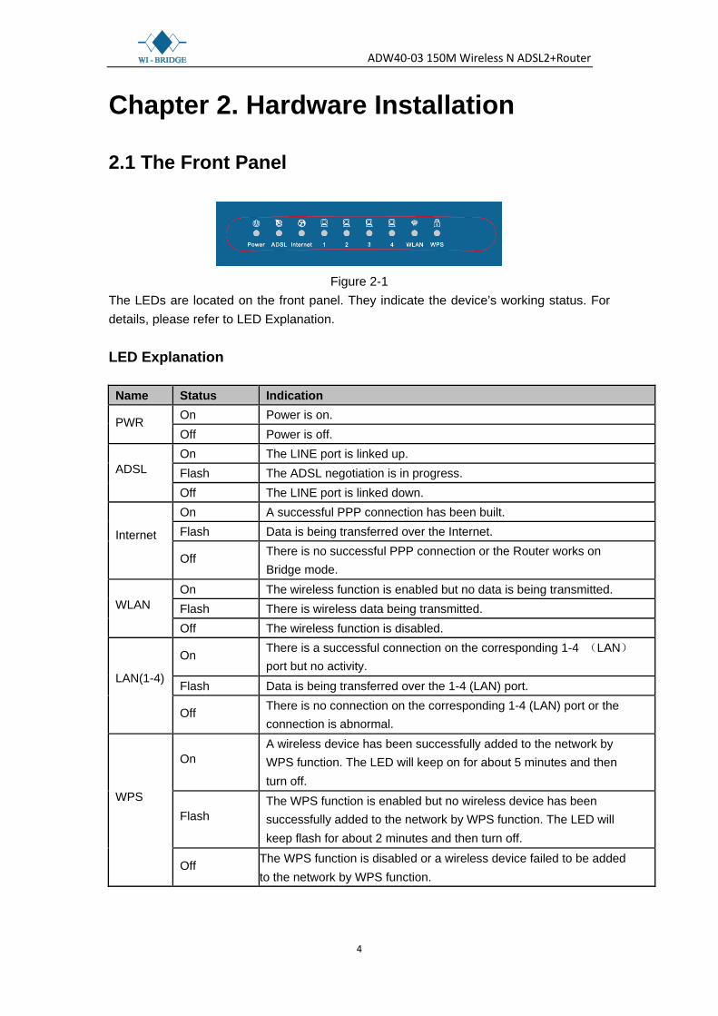
2.1 The Front Panel
Figure 2-1
The LEDs are located on the front panel. They indicate the device’s working status. For details, please refer to LED Explanation. LED Explanation
Name Status Indication
PWR On Power is on. Off Power is off.
ADSL On The LINE port is linked up. Flash The ADSL negotiation is in progress. Off The LINE port is linked down.
Internet
On A successful PPP connection has been built. Flash Data is being transferred over the Internet.
Off There is no successful PPP connection or the Router works on Bridge mode.
WLAN On The wireless function is enabled but no data is being transmitted. Flash There is wireless data being transmitted. Off The wireless function is disabled.
LAN(1-4)
On There is a successful connection on the corresponding 1-4 (LAN) port but no activity.
Flash Data is being transferred over the 1-4 (LAN) port.
Off There is no connection on the corresponding 1-4 (LAN) port or the connection is abnormal.
WPS
On A wireless device has been successfully added to the network by WPS function. The LED will keep on for about 5 minutes and then turn off.
Flash The WPS function is enabled but no wireless device has been successfully added to the network by WPS function. The LED will keep flash for about 2 minutes and then turn off.
Off The WPS function is disabled or a wireless device failed to be added to the network by WPS function.

ADW40-03 150M Wireless N ADSL2+Router
5
2.2 The Back Panel
Figure 2-2
POWER: The Power plug is where you will connect the power adapter. ON/OFF: The switch for the power. RESET: There are two ways to reset the Router's factory defaults. Method one: With the Router powered on, use a pin to press and hold the Reset
button for at least 5 seconds. And the Router will reboot to its factory default settings. Method two: Restore the default setting from “Maintenance-Reboot” of the Router's
Web-based Utility. 1, 2, 3, 4 (LAN): Through the port, you can connect the Router to your PC or the
other Ethernet network devices. DSL: Through the port, you can connect the router with the telephone. Or you can
connect them by an external separate splitter. For details, please refer to 2.4. Antenna: Used for wireless operation and data transmit. WPS: Used for encryption.
ADW40-03 150M Wireless N ADSL2+Router
6
2.3 Installation Environment
The Product should not be located where it will be exposed to moisture or excessive heat.
Place the Router in a location where it can be connected to the various devices as well as to a power source.
Make sure the cables and power cord are safely placed out of the way so they do not
create a tripping hazard. The Router can be placed on a shelf or desktop. Keep away from the strong electromagnetic radiation and the device of
electromagnetic sensitive.
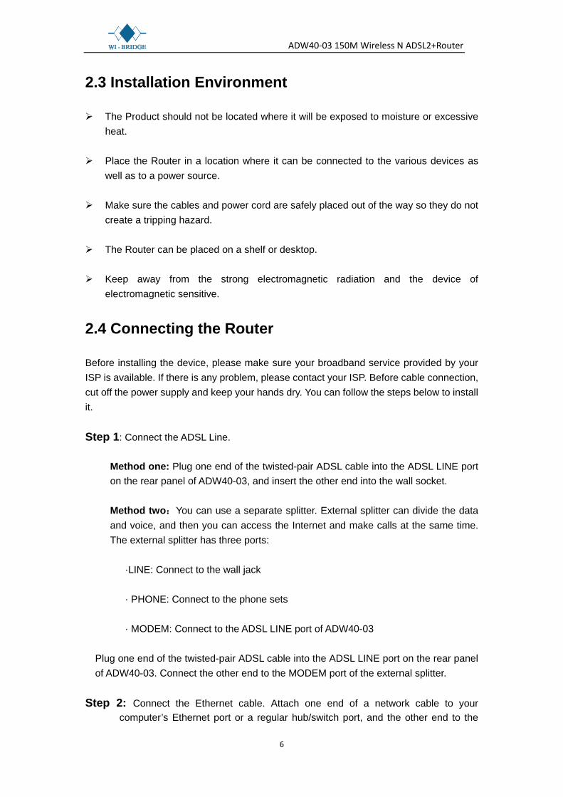
2.4 Connecting the Router
Before installing the device, please make sure your broadband service provided by your ISP is available. If there is any problem, please contact your ISP. Before cable connection, cut off the power supply and keep your hands dry. You can follow the steps below to install it. Step 1: Connect the ADSL Line.
Method one: Plug one end of the twisted-pair ADSL cable into the ADSL LINE port on the rear panel of ADW40-03, and insert the other end into the wall socket.
Method two:You can use a separate splitter. External splitter can divide the data and voice, and then you can access the Internet and make calls at the same time. The external splitter has three ports:
·LINE: Connect to the wall jack · PHONE: Connect to the phone sets · MODEM: Connect to the ADSL LINE port of ADW40-03
Plug one end of the twisted-pair ADSL cable into the ADSL LINE port on the rear panel of ADW40-03. Connect the other end to the MODEM port of the external splitter.
Step 2: Connect the Ethernet cable. Attach one end of a network cable to your
computer’s Ethernet port or a regular hub/switch port, and the other end to the
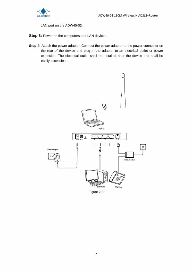
ADW40-03 150M Wireless N ADSL2+Router
7
LAN port on the ADW40-03. Step 3: Power on the computers and LAN devices. Step 4: Attach the power adapter. Connect the power adapter to the power connector on
the rear of the device and plug in the adapter to an electrical outlet or power extension. The electrical outlet shall be installed near the device and shall be easily accessible.
Figure 2-3
ADW40-03 150M Wireless N ADSL2+Router
8
Chapter 3. Quick Installation Guide
3.1 Configure PC
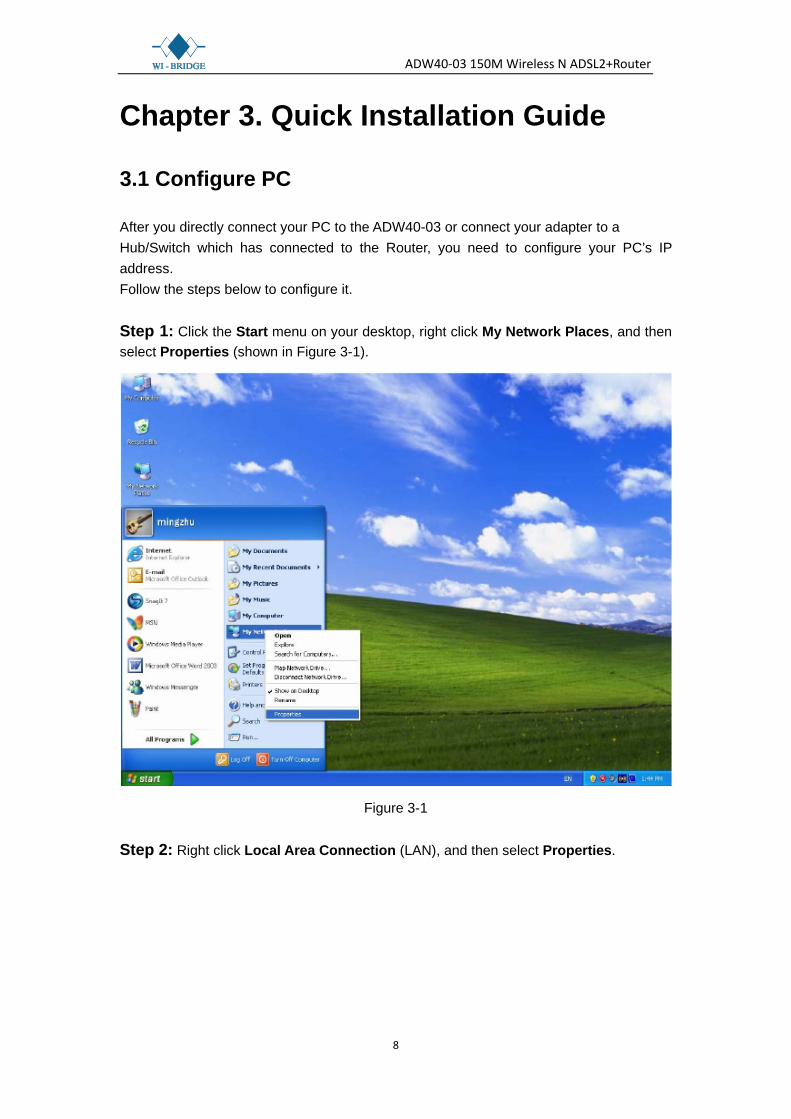
After you directly connect your PC to the ADW40-03 or connect your adapter to a Hub/Switch which has connected to the Router, you need to configure your PC’s IP address. Follow the steps below to configure it. Step 1: Click the Start menu on your desktop, right click My Network Places, and then select Properties (shown in Figure 3-1).
Figure 3-1 Step 2: Right click Local Area Connection (LAN), and then select Properties.

ADW40-03 150M Wireless N ADSL2+Router
9
Figure 3-2
Step 3: Select General tab, highlight Internet Protocol (TCP/IP), and then click the Properties button.
Figure 3-3

ADW40-03 150M Wireless N ADSL2+Router
10
Step 4: Configure the IP address as Figure 3-4 shows. After that, click OK.
Figure 3-4
Note:
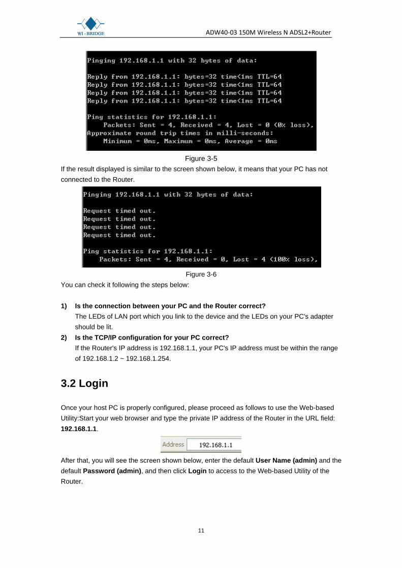
You can configure the PC to get an IP address automatically, select “Obtain an IP address automatically” and “Obtain DNS server address automatically” in the screen above. Now, you can run the Ping command in the command prompt to verify the network connection. Please click the Start menu on your desktop, select run tab, type cmd or command in the field and press Enter. Type ping 192.168.1.1 on the next screen, and then press Enter. If the result displayed is similar to the screen below, the connection between your PC and the Router has been established.
ADW40-03 150M Wireless N ADSL2+Router
11
Figure 3-5
If the result displayed is similar to the screen shown below, it means that your PC has not connected to the Router.
Figure 3-6
You can check it following the steps below: 1) Is the connection between your PC and the Router correct?
The LEDs of LAN port which you link to the device and the LEDs on your PC's adapter should be lit.
2) Is the TCP/IP configuration for your PC correct? If the Router's IP address is 192.168.1.1, your PC's IP address must be within the range of 192.168.1.2 ~ 192.168.1.254.
3.2 Login
Once your host PC is properly configured, please proceed as follows to use the Web-based Utility:Start your web browser and type the private IP address of the Router in the URL field: 192.168.1.1.
After that, you will see the screen shown below, enter the default User Name (admin) and the default Password (admin), and then click Login to access to the Web-based Utility of the Router.
ADW40-03 150M Wireless N ADSL2+Router
12
Figure 3-7
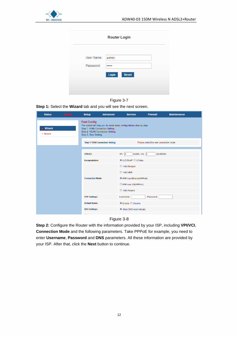
Step 1: Select the Wizard tab and you will see the next screen.
Figure 3-8
Step 2: Configure the Router with the information provided by your ISP, including VPI/VCI, Connection Mode and the following parameters. Take PPPoE for example, you need to enter Username, Password and DNS parameters. All these information are provided by your ISP. After that, click the Next button to continue.
ADW40-03 150M Wireless N ADSL2+Router
13
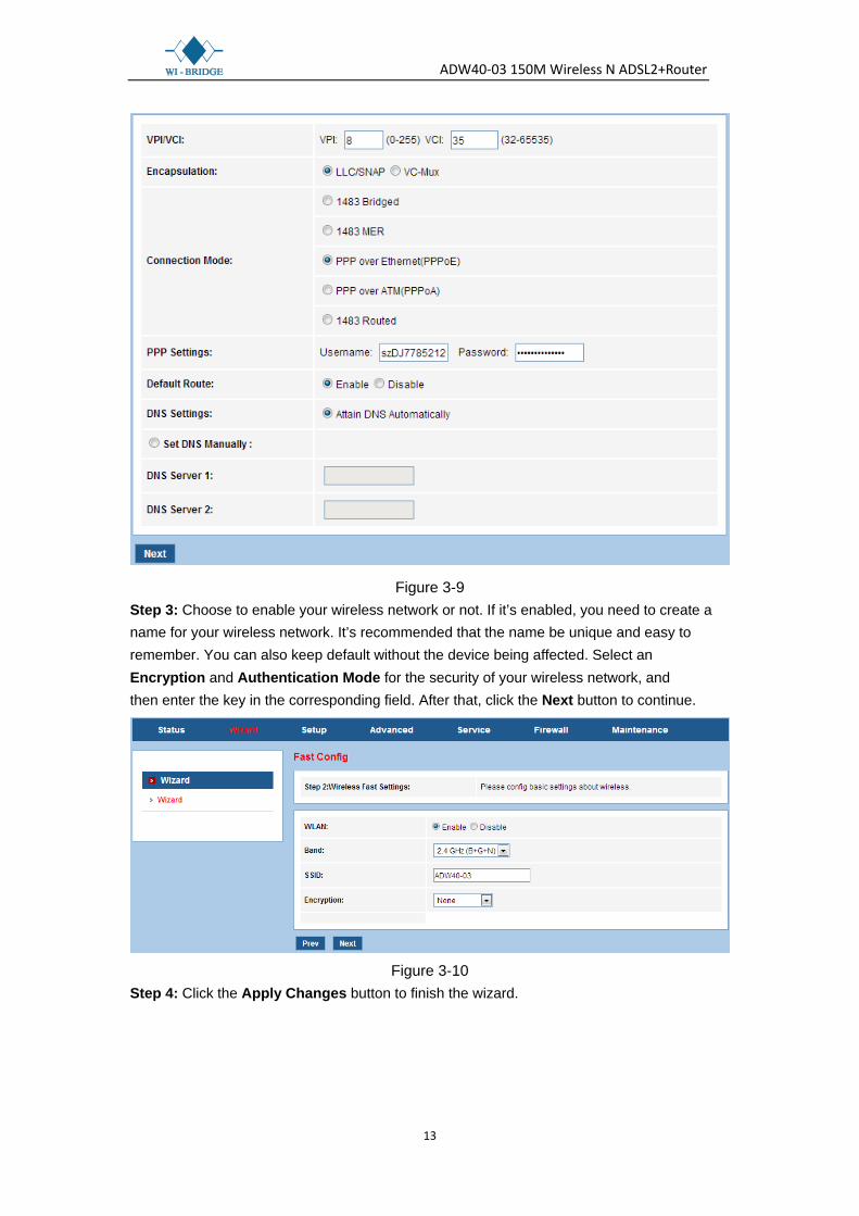
Figure 3-9 Step 3: Choose to enable your wireless network or not. If it’s enabled, you need to create a name for your wireless network. It’s recommended that the name be unique and easy to remember. You can also keep default without the device being affected. Select an Encryption and Authentication Mode for the security of your wireless network, and then enter the key in the corresponding field. After that, click the Next button to continue.
Figure 3-10
Step 4: Click the Apply Changes button to finish the wizard.

ADW40-03 150M Wireless N ADSL2+Router
14
Figure 3-11
Chapter 4. Software Configuration This User Guide recommends using the “Quick Installation Guide” for first-time installation. For advanced users, if you want to know more about this device and make use of its functions adequately, maybe you will get help from this chapter to configure the advanced settings through the Web-based Utility. After your successful login, you can configure and manage the device. There are main menus on the top of the Web-based Utility; submenus will be available after you click one of the main menus.On the center of the Web-based Utility, there are the detailed configurations or status information.To apply any settings you have altered on the page, please click the SAVE button.
4.1 Status
Choose “Status”, you can see the next submenus: Device Info,ADSL and Statistics. Click any of them,and you will be able to configure the corresponding function.
Click any of them, and you will be able to view the corresponding information.

ADW40-03 150M Wireless N ADSL2+Router
15
4.1.1 Device_Info
4.1.1.1 Device_Info
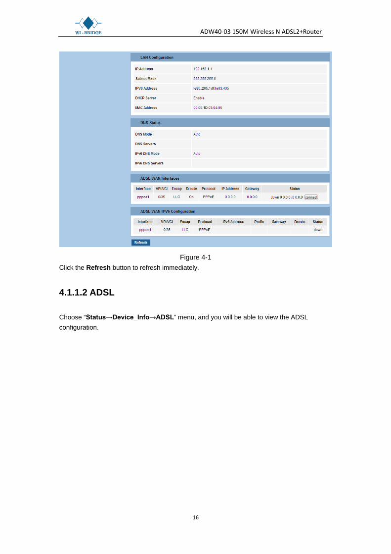
Choose “Status→Device_Info→Device_Info” menu, and you will be able to view the device information, including System, DSL, LAN, DNS, and WAN. The information will vary depending on the settings of the Router.
ADW40-03 150M Wireless N ADSL2+Router
16
Figure 4-1 Click the Refresh button to refresh immediately.
4.1.1.2 ADSL
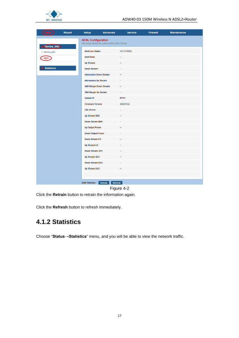
Choose “Status→Device_Info→ADSL” menu, and you will be able to view the ADSL configuration.
ADW40-03 150M Wireless N ADSL2+Router
17
Figure 4-2
Click the Retrain button to retrain the information again. Click the Refresh button to refresh immediately.
4.1.2 Statistics
Choose “Status→Statistics” menu, and you will be able to view the network traffic.

ADW40-03 150M Wireless N ADSL2+Router
18
Figure 4-3
Click the Refresh button to refresh immediately.
4.1.3 Wizard
Please refer to “3.2 Login".
4.2 Setup
Choose “Setup”, you can see the next submenus: WAN, LAN and WLAN.
Click any of them, and you will be able to configure the corresponding function.
4.2.1 WAN
4.2.1.1 WAN
Choose “Setup→WAN→WAN” menu, you can configure the parameters for WAN in the next screen (shown in Figure 4-4).

ADW40-03 150M Wireless N ADSL2+Router
19
Figure 4-4
Current ATM VC Table: ATM settings are used to connect to your ISP. Your ISP provides VPI (Virtual Path Identifier), VCI (Virtual Channel Identifier) settings to you. In this Device, there is one VC configured by default. You can totally setup 8 VCs on different encapsulations, if you apply 8 different virtual circuits from your ISP. You need to activate the VC to take effect.
: Click this icon to enter the VC modification page. Besides, some advanced settings can be configured there.
: Click this icon to delete the corresponding VC. VPI: Identifies the virtual path between endpoints in an ATM network. The valid range is
from 0 to 255. Please input the value provided by your ISP. VCI: Identifies the virtual channel endpoints in an ATM network. The valid range is from
32 to 65535 (1 to 31 is reserved for well-known protocols). Please input the value provided by your ISP.
Encapsulation: Specifies the type of Multiplexing, either LLC or VC-Mux. Please note that VC-Mux is not available for IPoA channel mode.
Channel Mode: There are six channel modes, 1483 Bridged, 1483 MER, PPPoE, PPPoA, 1483 Routed and IPoA. Please choose the mode that you want to use.

ADW40-03 150M Wireless N ADSL2+Router
20
Enable NAPT: Choose to enable the NAPT function or not. Enable IGMP: Choose to enable the IGMP function or not.
PPP Settings: These parameters are only available for PPPoE and PPPoA channel
mode. User Name: Enter your user name for your PPPoE/PPPoA connection. Password: Enter your password for your PPPoE/PPPoA connection. Type: Select Continuous, Connect on Demand or Manually for the network
connection. Continuous means the Internet connection will always keep on. Connect on demand is dependent on the traffic. If it’s idle (there is no traffic) for a pre-specified period of time), the connection will tear down automatically. And once there is traffic send or receive, the connection will be automatically on. Manually means you have to manually connect or disconnect your Internet by clicking the Connect or Disconnect button at the bottom of this page.
Idle Time (min): Specifies the idle time for Connect on Demand type. WAN IP Settings: These parameters are only available for 1483 MER and 1483 Routed
channel mode. Please note that for1483 Routed mode, DHCP is not available. Type: Selects to use Fixed IP or DHCP. If Fixed IP is selected, then you have to fill the
following parameters, including Local IP Address, Remote IP Address, and Netmask. Otherwise, these parameters will not be available.
Local IP Address: The IP address of the router on the PVC channel. Remote IP Address: The gateway’s IP address of the router on the PVC channel. Netmask: The subnet mask of the router on the PVC channel.
Connect/Disconnect: When there is a VC using PPPoE/PPPoA channel and Manually
type, you need to click this button to connect/disconnect the network. Add: Click this button to add a VC. First fill the parameters above and then click this
button, thus your new VC will be added to the Current ATM VC Table. Modify: Click this button to modify your existed VC. First choose the desired VC and
modify the parameters, and then click this button, thus your existed VC will be modified. Delete: Click this button to delete your existed VC. First choose the desired VC, and then
click this button, thus your existed VC will be deleted. Undo: Click this button to abandon your operation. Refresh: Click this button to refresh the ATM VC table.
Note:
After configuration, you need to click the Save button appeared on the left panel so that your configuration can still take effect after the Router reboots.

ADW40-03 150M Wireless N ADSL2+Router
21
4.2.1.2 ATM
Choose “Setup→WAN→ATM” menu, you can configure the parameters for the ATM of your ADSL Router in the next screen (shown in Figure 4-5). Here you may change the setting for QoS,PCR, CDVT, SCR and MBS.
Figure 4-5 VPI/VCI: Choose a desired ATM VC, and the VPI/VCI value will be displayed. The values
cannot be changed.
QoS: Select the Quality of Service types for the Virtual Circuit, including UBR (Unspecified Bit Rate), CBR (Constant Bit Rate), and nrt-VBR (Variable Bit Rate) and rt-VBR. Please note that the selection of QoS type will lead to the availability of the following parameters, including PCR (Peak Cell Rate), CDVT (Cell Delay Variation Tolerance), SCR (Sustained Cell Rate) and MBS (Maximum Burst Size). Please configure them according to your needs.
Click Apply Changes to save your configuration.
Note:
After configuration, you need to click the Save button appeared on the left panel so that your configuration can still take effect after the Router reboots.
4.2.1.3 ADSL
Choose “Setup→WAN→ADSL” menu, you can configure some advanced parameters for your ADSL Router in the next screen (shown in Figure 4-6).

ADW40-03 150M Wireless N ADSL2+Router
22
Figure 4-6 After configuration, click Apply Changes button to save your changes.
Note:
After configuration, you need to click the Save button appeared on the left panel so that your configuration can still take effect after the Router reboots.
4.2.2 LAN
4.2.2.1 LAN
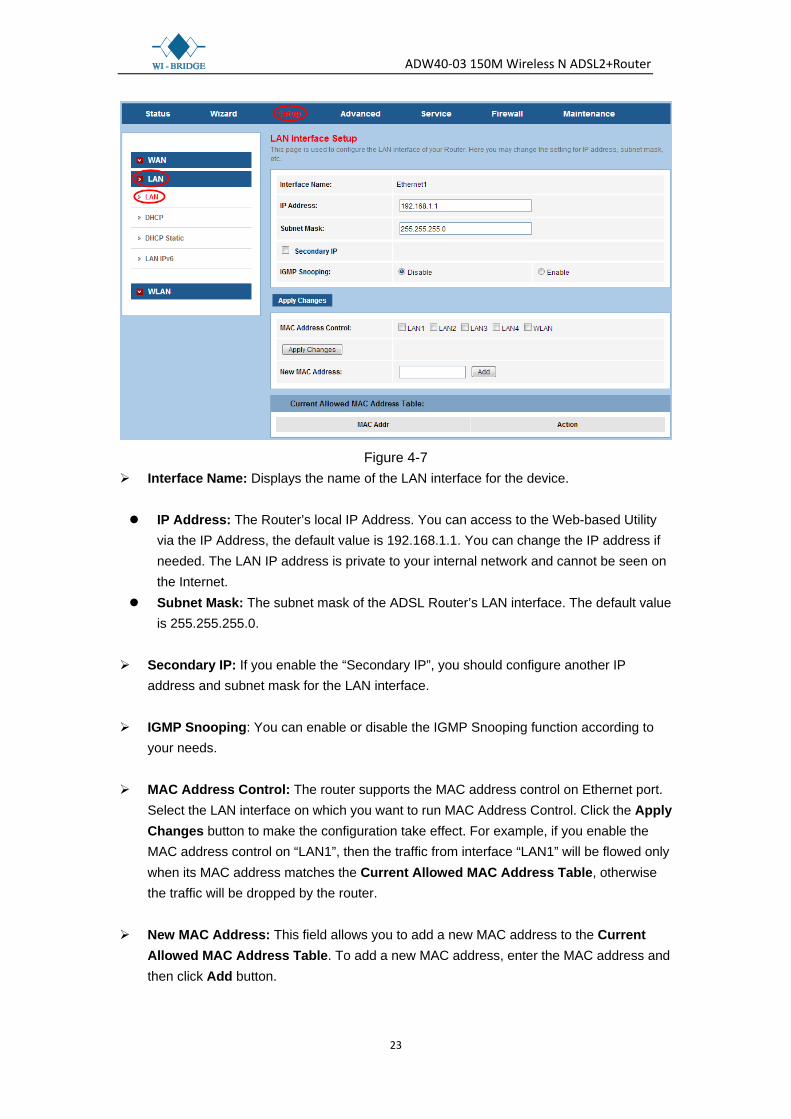
Choose “Setup→LAN→LAN” menu, and you will see the LAN Interface Setup screen (shown in Figure 4-7). Here you can change IP address, subnet mask and other parameters for LAN interface.
ADW40-03 150M Wireless N ADSL2+Router
23
Figure 4-7
Interface Name: Displays the name of the LAN interface for the device.
IP Address: The Router’s local IP Address. You can access to the Web-based Utility via the IP Address, the default value is 192.168.1.1. You can change the IP address if needed. The LAN IP address is private to your internal network and cannot be seen on the Internet.
Subnet Mask: The subnet mask of the ADSL Router’s LAN interface. The default value is 255.255.255.0.
Secondary IP: If you enable the “Secondary IP”, you should configure another IP address and subnet mask for the LAN interface.
IGMP Snooping: You can enable or disable the IGMP Snooping function according to your needs.
MAC Address Control: The router supports the MAC address control on Ethernet port.
Select the LAN interface on which you want to run MAC Address Control. Click the Apply Changes button to make the configuration take effect. For example, if you enable the MAC address control on “LAN1”, then the traffic from interface “LAN1” will be flowed only when its MAC address matches the Current Allowed MAC Address Table, otherwise the traffic will be dropped by the router.
New MAC Address: This field allows you to add a new MAC address to the Current
Allowed MAC Address Table. To add a new MAC address, enter the MAC address and then click Add button.

ADW40-03 150M Wireless N ADSL2+Router
24
Current Allowed MAC Address Table: Displays the current allowed MAC address. Click the Delete button and then the corresponding MAC address will be deleted.
After configuration, click Apply Changes button to save your changes.
Note:
After configuration, you need to click the Save button appeared on the left panel so that your configuration can still take effect after the Router reboots.
4.2.2.2 DHCP
Choose “Setup→LAN→DHCP” menu, and then you will see the DHCP Mode screen (shown in Figure 4-8). Here you can configure the DHCP mode of your ADSL Router as None, DHCP Relay or DHCP Server. DHCP stands for Dynamic Host Control Protocol. The DHCP Server gives out IP addresses when a device is booting up and request an IP address to be logged on to the network.
Figure 4-8
LAN IP Address: Displays the LAN IP address of the Modem Router Subnet Mask: Displays the subnet mask of the Modem Router.

ADW40-03 150M Wireless N ADSL2+Router
25
DHCP Mode: Options available are None, DHCP Relay and DHCP Server. 1) None: In this mode, the Modem Router will do nothing when the host requests an IP
address by DHCP protocol. The screen will be shown as in Figure 4-9.
Figure 4-9
2) DHCP Relay: In this mode, the Router will work as a DHCP Relay. A DHCP relay is a device that forwards DHCP data between computers that request IP addresses and the DHCP server that assigns the addresses. Each of the device's interfaces can be configured as a DHCP relay. In this mode, the DHCP requests from local PCs will be forwarded to the DHCP server running on WAN side.
Figure 4-10
Relay Server: Enter the IP Address of the DHCP server running on WAN side. 3) DHCP Server: Select this mode, then the screen will be shown as in Figure 4-11. The
Router will work as a DHCP Server; it becomes the default gateway for DHCP client connected to it.That device on your local network must be set as a DHCP client to obtain the IP address automatically. By default, the DHCP Server is enabled.

ADW40-03 150M Wireless N ADSL2+Router
26
Figure 4-11
IP Pool Range: Specify the start and end IP address for the DHCP server's IP assignment. The default start and end IP Address are 192.168.1.100 and 192.168.1.200 separately. Please note that both addresses should be smaller than 192.168.1.254.
Default Gateway: The default gateway address. Max Lease Time: The time that the DHCP client is allowed to maintain the assigned
dynamic IP. After the dynamic IP address has expired, the user will be automatically assigned a new one. The default is 1440 minutes.
Domain Name: Specify a user-friendly name to refer to the group of hosts (subnet) that
will be assigned addresses from this pool. DNS Servers: The IP address of DNS server used in option filed of DHCP message. Apply Changes: Click this button to save your configuration. Undo: Click this button to cancel your configuration. Set VendorClass IP Range: Click this button and then you will enter the screen as
ADW40-03 150M Wireless N ADSL2+Router
27
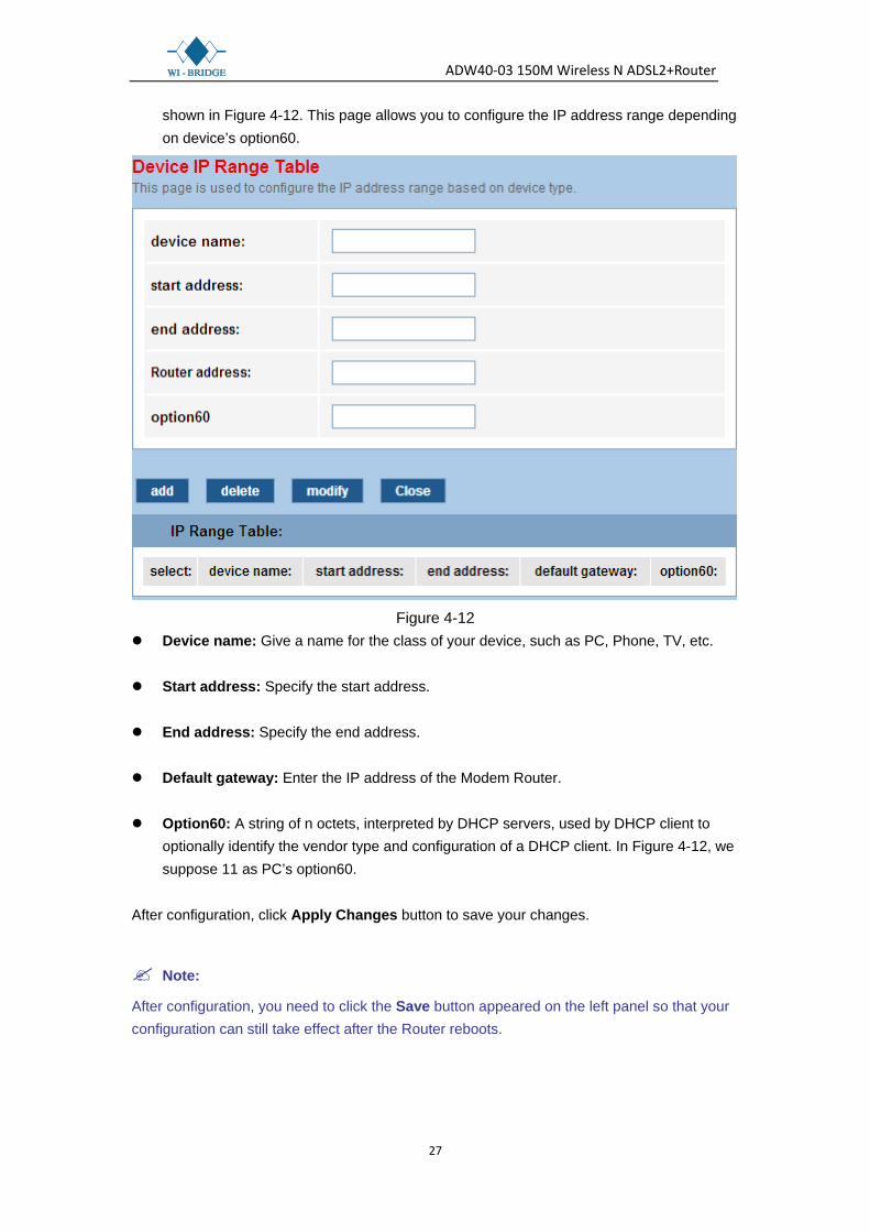
shown in Figure 4-12. This page allows you to configure the IP address range depending on device’s option60.
Figure 4-12
Device name: Give a name for the class of your device, such as PC, Phone, TV, etc. Start address: Specify the start address. End address: Specify the end address. Default gateway: Enter the IP address of the Modem Router. Option60: A string of n octets, interpreted by DHCP servers, used by DHCP client to
optionally identify the vendor type and configuration of a DHCP client. In Figure 4-12, we suppose 11 as PC’s option60.
After configuration, click Apply Changes button to save your changes.
Note:
After configuration, you need to click the Save button appeared on the left panel so that your configuration can still take effect after the Router reboots.

ADW40-03 150M Wireless N ADSL2+Router
28
4.2.2.3 DHCP Static
Choose “Setup→LAN→DHCP Static” menu, you can view and add a static address for client via the next screen (shown in Figure 4-13). When you specify a static IP address for a PC on the LAN, that PC will always receive the same IP address each time when it accesses the DHCP server. Static IP address is recommended to be assigned to the client that requires permanent IP settings.
Figure 4-13
IP Address: Enter the IP address desired to be assigned to the client. Mac Address: Enter the MAC address of the client. Add: Click this button to add a new static IP entry. Delete Selected: Click this button to delete the selected entry in the DHCP Static IP
Table. Undo: Click this button to delete your entering.
Note:
After configuration, you need to click the Save button appeared on the left panel so you’re your configuration can still take effect after the Router reboots.
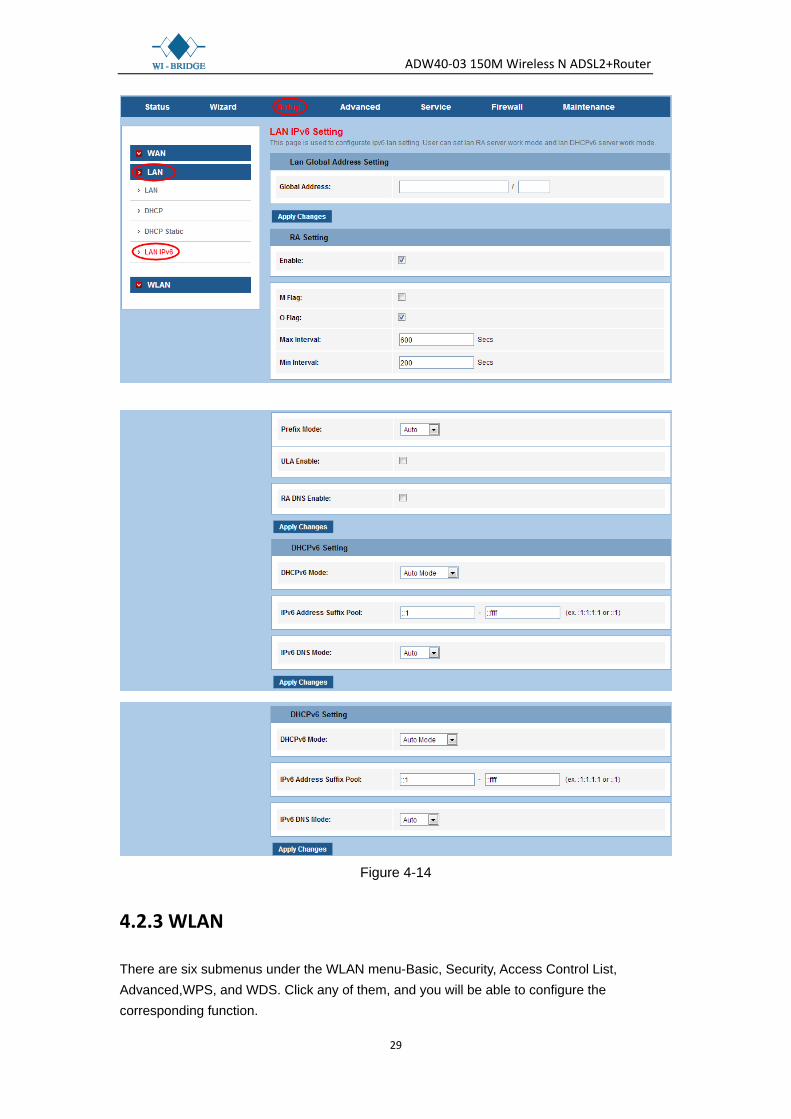
4.2.2.4 LAN IPv6
Choose “Setup→LAN→LAN IPv6” menu, you can see the LAN IPv6 Setting screen (shown in Figure 4-14).
ADW40-03 150M Wireless N ADSL2+Router
29
Figure 4-14
4.2.3 WLAN
There are six submenus under the WLAN menu-Basic, Security, Access Control List, Advanced,WPS, and WDS. Click any of them, and you will be able to configure the corresponding function.
ADW40-03 150M Wireless N ADSL2+Router
30
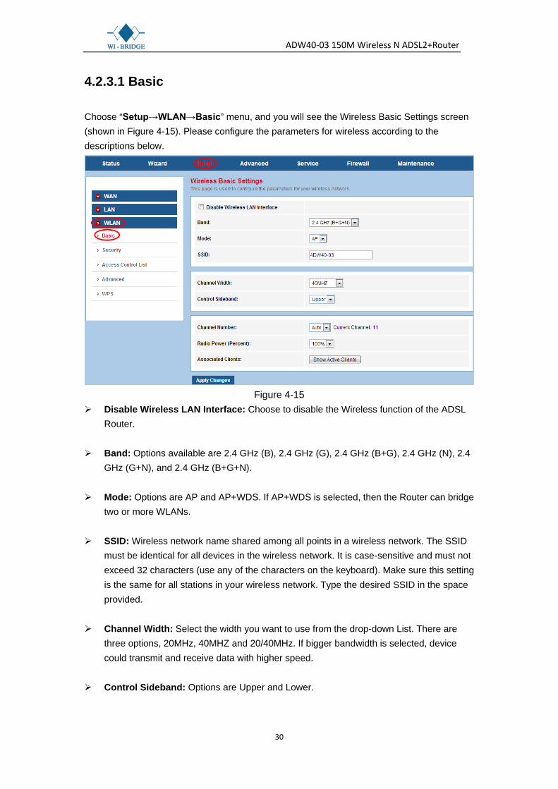
4.2.3.1 Basic
Choose “Setup→WLAN→Basic” menu, and you will see the Wireless Basic Settings screen (shown in Figure 4-15). Please configure the parameters for wireless according to the descriptions below.
Figure 4-15
Disable Wireless LAN Interface: Choose to disable the Wireless function of the ADSL Router.
Band: Options available are 2.4 GHz (B), 2.4 GHz (G), 2.4 GHz (B+G), 2.4 GHz (N), 2.4
GHz (G+N), and 2.4 GHz (B+G+N). Mode: Options are AP and AP+WDS. If AP+WDS is selected, then the Router can bridge
two or more WLANs. SSID: Wireless network name shared among all points in a wireless network. The SSID
must be identical for all devices in the wireless network. It is case-sensitive and must not exceed 32 characters (use any of the characters on the keyboard). Make sure this setting is the same for all stations in your wireless network. Type the desired SSID in the space provided.
Channel Width: Select the width you want to use from the drop-down List. There are
three options, 20MHz, 40MHZ and 20/40MHz. If bigger bandwidth is selected, device could transmit and receive data with higher speed.
Control Sideband: Options are Upper and Lower.

ADW40-03 150M Wireless N ADSL2+Router
31
Channel Number: This field determines which operating frequency will be used. Select the channel to use from the drop-down list. It is not necessary to change the default channel unless you notice interference problems with another nearby access point.
Radio Power (Percent): Here you can specify the Radio Power of Router. You can select
High, Middle or Low which you would like. High is the default setting and is recommended.
Associated Clients: Click the Show Active Clients button to view the information of
wireless clients that connects to the ADSL Router. Click Apply Changes button to save your changes.
Note:
After configuration, you need to click the Save button appeared on the left panel so that your configuration can still take effect after the Router reboots.
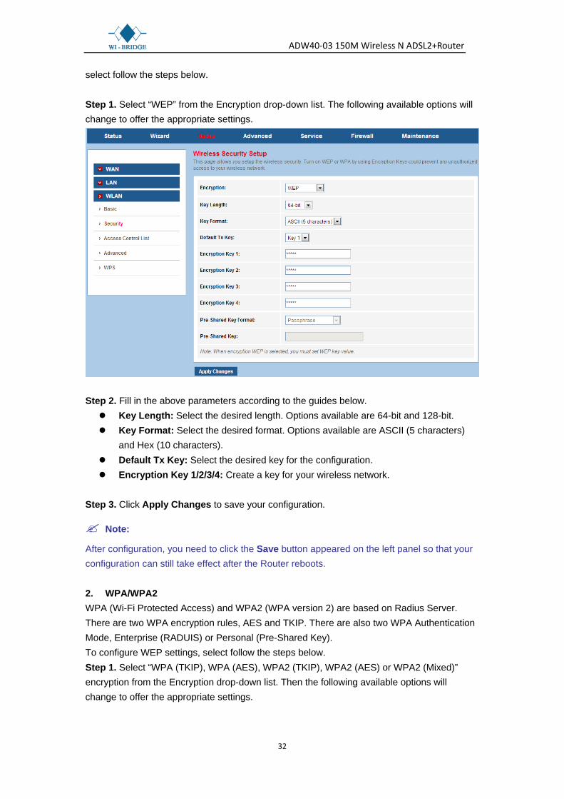
4.2.3.2 Security
Choose “Setup→WLAN→Security” menu, and you will see the Wireless Security Setup screen (shown in Figure 4-16). Here you can configure the security settings of your wireless network. There are six encryptions supported by the Router: WEP, WPA (TKIP), WPA (AES), WPA2 (AES), WPA2 (TKIP) and WPA2 Mixed.
Figure 4-16
Encryption: There are six encryptions supported by the Router: WEP, WPA (TKIP), WPA (AES), WPA2 (AES), WPA2 (TKIP) and WPA2 Mixed. Use 802.1x Authentication: If you want to use the authentication, check this box and
then set the port, IP address and password for the Authentication RADIUS Server. 1. WEP WEP (Wired Equivalent Privacy) is a data privacy mechanism based on a 64-bit and 128-bit shared key algorithm, as described in the IEEE 802.11g standard. To configure WEP settings,
ADW40-03 150M Wireless N ADSL2+Router
32
select follow the steps below. Step 1. Select “WEP” from the Encryption drop-down list. The following available options will change to offer the appropriate settings.
Step 2. Fill in the above parameters according to the guides below. Key Length: Select the desired length. Options available are 64-bit and 128-bit. Key Format: Select the desired format. Options available are ASCII (5 characters)
and Hex (10 characters). Default Tx Key: Select the desired key for the configuration. Encryption Key 1/2/3/4: Create a key for your wireless network.
Step 3. Click Apply Changes to save your configuration.
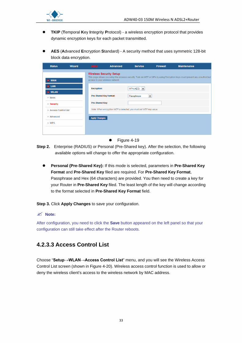
Note:
After configuration, you need to click the Save button appeared on the left panel so that your configuration can still take effect after the Router reboots. 2. WPA/WPA2 WPA (Wi-Fi Protected Access) and WPA2 (WPA version 2) are based on Radius Server. There are two WPA encryption rules, AES and TKIP. There are also two WPA Authentication Mode, Enterprise (RADUIS) or Personal (Pre-Shared Key). To configure WEP settings, select follow the steps below. Step 1. Select “WPA (TKIP), WPA (AES), WPA2 (TKIP), WPA2 (AES) or WPA2 (Mixed)” encryption from the Encryption drop-down list. Then the following available options will change to offer the appropriate settings.
ADW40-03 150M Wireless N ADSL2+Router
33
TKIP (Temporal Key Integrity Protocol) - a wireless encryption protocol that provides dynamic encryption keys for each packet transmitted.
AES (Advanced Encryption Standard) - A security method that uses symmetric 128-bit block data encryption.
Figure 4-19
Step 2. Enterprise (RADIUS) or Personal (Pre-Shared key). After the selection, the following available options will change to offer the appropriate configuration.
Personal (Pre-Shared Key): If this mode is selected, parameters in Pre-Shared Key
Format and Pre-Shared Key filed are required. For Pre-Shared Key Format, Passphrase and Hex (64 characters) are provided. You then need to create a key for your Router in Pre-Shared Key filed. The least length of the key will change according to the format selected in Pre-Shared Key Format field.
Step 3. Click Apply Changes to save your configuration.
Note:
After configuration, you need to click the Save button appeared on the left panel so that your configuration can still take effect after the Router reboots.
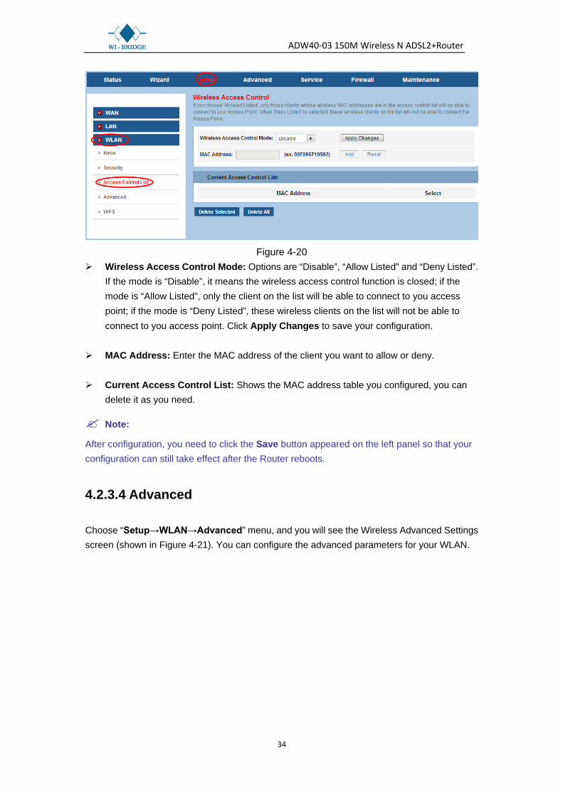
4.2.3.3 Access Control List
Choose “Setup→WLAN→Access Control List” menu, and you will see the Wireless Access Control List screen (shown in Figure 4-20). Wireless access control function is used to allow or deny the wireless client’s access to the wireless network by MAC address.
ADW40-03 150M Wireless N ADSL2+Router
34
Figure 4-20
Wireless Access Control Mode: Options are “Disable”, “Allow Listed” and “Deny Listed”. If the mode is “Disable”, it means the wireless access control function is closed; if the mode is “Allow Listed”, only the client on the list will be able to connect to you access point; if the mode is “Deny Listed”, these wireless clients on the list will not be able to connect to you access point. Click Apply Changes to save your configuration.
MAC Address: Enter the MAC address of the client you want to allow or deny. Current Access Control List: Shows the MAC address table you configured, you can
delete it as you need.
Note:
After configuration, you need to click the Save button appeared on the left panel so that your configuration can still take effect after the Router reboots.
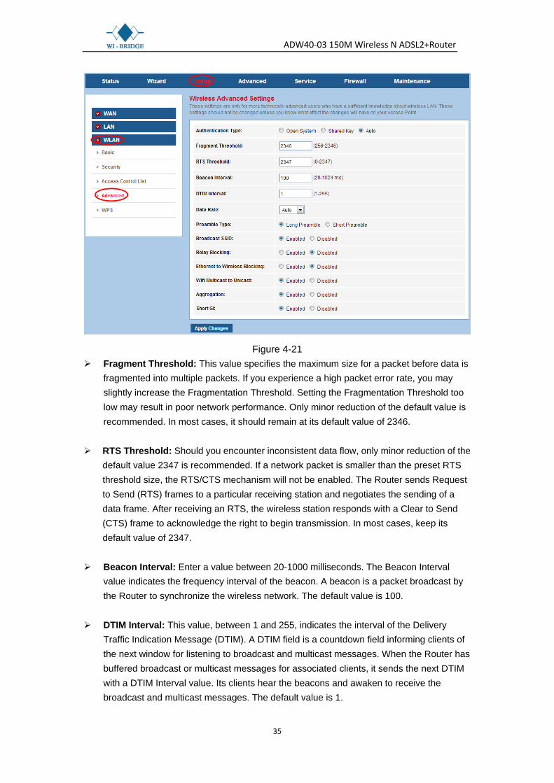
4.2.3.4 Advanced
Choose “Setup→WLAN→Advanced” menu, and you will see the Wireless Advanced Settings screen (shown in Figure 4-21). You can configure the advanced parameters for your WLAN.
ADW40-03 150M Wireless N ADSL2+Router
35
Figure 4-21 Fragment Threshold: This value specifies the maximum size for a packet before data is
fragmented into multiple packets. If you experience a high packet error rate, you may slightly increase the Fragmentation Threshold. Setting the Fragmentation Threshold too low may result in poor network performance. Only minor reduction of the default value is recommended. In most cases, it should remain at its default value of 2346.
RTS Threshold: Should you encounter inconsistent data flow, only minor reduction of the
default value 2347 is recommended. If a network packet is smaller than the preset RTS threshold size, the RTS/CTS mechanism will not be enabled. The Router sends Request to Send (RTS) frames to a particular receiving station and negotiates the sending of a data frame. After receiving an RTS, the wireless station responds with a Clear to Send (CTS) frame to acknowledge the right to begin transmission. In most cases, keep its default value of 2347.
Beacon Interval: Enter a value between 20-1000 milliseconds. The Beacon Interval
value indicates the frequency interval of the beacon. A beacon is a packet broadcast by the Router to synchronize the wireless network. The default value is 100.
DTIM Interval: This value, between 1 and 255, indicates the interval of the Delivery
Traffic Indication Message (DTIM). A DTIM field is a countdown field informing clients of the next window for listening to broadcast and multicast messages. When the Router has buffered broadcast or multicast messages for associated clients, it sends the next DTIM with a DTIM Interval value. Its clients hear the beacons and awaken to receive the broadcast and multicast messages. The default value is 1.

ADW40-03 150M Wireless N ADSL2+Router
36
Broadcast SSID: When wireless clients survey the local area for wireless networks to
associate with, they will detect the SSID broadcast by the Router. To broadcast the Router’s SSID, select “Enable”. If you don’t want to broadcast the Router’s SSID, select “Disable”.
After configuration, click Apply Changes button to save your changes.
Note:
1. These settings are only for more technically advanced users who have a sufficient knowledge about wireless LAN. They should not be changed unless you know exactly what will happen for the changes on your Access Point.
2. After configuration, you need to click the Save button appeared on the left panel so that your configuration can still take effect after the Router reboots.
4.2.3.5 WPS
Choose “Setup→WLAN→WPS” menu, and you will see the Wi-Fi Protected Setup screen (shown in Figure 4-22). Wi-Fi Protected Setup (WPS) is a simple way to establish the connection between the wireless client and access point. You don’t need to select the encryption method and encryption key. You just need to input the correct PIN or start PBC and press the WPS/WLAN button on the router to set the WPS.
Figure 4-22
Disable WPS: Select to disable WPS function. WPS state: Display the current WPS state.
Self PIN Number: Displays the PIN number of the Router. You can click the Regenerate
PIN button to generate a new PIN number. Push Button Configuration: Click Start PBC button when using PBC method for WPS
configuration.
ADW40-03 150M Wireless N ADSL2+Router
37
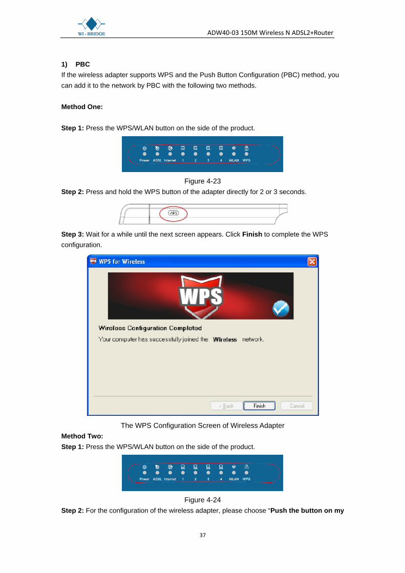
1) PBC If the wireless adapter supports WPS and the Push Button Configuration (PBC) method, you can add it to the network by PBC with the following two methods. Method One: Step 1: Press the WPS/WLAN button on the side of the product.
Figure 4-23
Step 2: Press and hold the WPS button of the adapter directly for 2 or 3 seconds.
Step 3: Wait for a while until the next screen appears. Click Finish to complete the WPS configuration.
The WPS Configuration Screen of Wireless Adapter
Method Two: Step 1: Press the WPS/WLAN button on the side of the product.
Figure 4-24
Step 2: For the configuration of the wireless adapter, please choose “Push the button on my

ADW40-03 150M Wireless N ADSL2+Router
38
access point” in the configuration utility of the WPS as below, and click Next.
The WPS Configuration Screen of Wireless Adapter
Step 3: Wait for a while until the next screen appears. Click Finish to complete the WPS configuration.
The WPS Configuration Screen of Wireless Adapter
2) PIN code If the wireless adapter supports WPS and the PIN method, you can add it to the network by PIN with the following two methods.

ADW40-03 150M Wireless N ADSL2+Router
39
Method One: Enter the PIN into my Router Step 1: For the configuration of the wireless adapter, please choose “Enter a PIN into my access point or a registrar” in the configuration utility of the WPS, and get the PIN code on the screen as below, then click Next.
The WPS Configuration Screen of Wireless Adapter
Step 2: For the Router, enter the PIN code of the wireless adapter in the Client PIN Number field as shown below. Then click Start PIN.
Figure 4-25
Method Two: Enter the PIN from my Router Step 1: Get the Current PIN code of the Router from Self-PIN Number in Figure 4-24 (each Router has its unique PIN code. Here takes the PIN code 12345670 of this Router for example). Step 2: For the configuration of the wireless adapter, please choose “Enter a PIN from my access point” in the configuration utility of the WPS as below, and enter the PIN code of

ADW40-03 150M Wireless N ADSL2+Router
40
the Router into the Access Point PIN field. Then click Next.
The WPS Configuration Screen of Wireless Adapter
Note:
1. The default PIN code of the Router can be found in its label or the WPS configuration screen as shown in Figure 4-24.
2. After saving your configuration, you need to click the Save button on the left panel to make your configuration take effect.
4.3 Advanced
Choose “Advanced”, you can see the next submenus:
Click any of them, and you will be able to configure the corresponding function.

ADW40-03 150M Wireless N ADSL2+Router
41
4.3.1 Route
4.3.1.1 Static Route
Choose “Advanced→Route→Static Route” menu, you can configure the routing information in the next screen (shown in Figure 4-26). Here you can add or delete IP routes.
Figure 4-26 Enable: Check the box to enable this function. Destination: Enter the IP network address of the final destination. It can be a subnet IP or
a host address. All zeros indicate that the route entry should be used for all destinations for which no other route is defined.
Subnet Mask: Enter the subnet mask of the destination. Next Hop: The IP address of the next hop through which traffic will forward the
destination. Interface: Select the interface to which a static route is to be applied. Click the Add Route button to add the new route in the Static Route Table. The Static Route Table shows the current static route entries.
Note:
After configuration, you need to click the Save button appeared on the left panel so that your configuration can still take effect after the Router reboots.

ADW40-03 150M Wireless N ADSL2+Router
42
4.3.1.2 IPv6 Static Route
Choose “Advanced→Route→IPv6 Static Route” menu, you can configure the routing information in the next screen (shown in Figure 4-27). Here you can add or delete IPv6 routes.
Figure 4-27
4.3.1.3 RIP
Choose “Advanced→Route→RIP” menu, you can configure the RIP settings in the next screen (shown in Figure 4-28). RIP is an internet protocol you can set up to share routing table information with other routing devices.
Figure 4-28
RIP: Select to enable the RIP function or not. Click the Apply button to you’re your configuration.
Interface: Select the interface on which you want to enable RIP.

ADW40-03 150M Wireless N ADSL2+Router
43
Recv Version: Indicate the RIP version in which information must be passed to the device. It can be accepted into its routing table.
Send Version: Indicate the RIP version this interface will use when it sends its route
information to the other device.
Click the Add button to add a RIP configuration to the Rip Config List. Click the Delete button to delete it. The RIP Config List shows the current RIP setting of the device.
Note:
After adding a new entry, a Save button will appear on the left panel. You need to click the Save button to make your changes take effect.
4.3.2 NAT
4.3.2.1 DMZ
Choose “Advanced→NAT→DMZ”, you can configure the DMZ host in the screen as shown in Figure 4-29. A DMZ (Demilitarized Zone) is a host between a private local network and the outside public network. It allows a single host on your LAN to expose all of its ports to the Internet. Users of the public network outside the company can access to the DMZ host.
Figure 4-29

ADW40-03 150M Wireless N ADSL2+Router
44
DMZ Host IP Address: Enter the specified IP Address for DMZ host on the LAN side. Click Apply Changes to save your configuration.
Note:
After configuration, you need to click the Save button appeared on the left panel so that your configuration can still take effect after the Router reboots.
4.3.2.2 Virtual Server
Choose “Advanced→NAT→Virtual Server”, and then you can configure the Virtual Server in the screen as shown in Figure 4-30. The Virtual Server is the server or server(s) behind NAT (on the LAN). It allows a single host on your LAN to provide the specified service to the Internet, for example Web server or FTP server, which you can make visible to the outside world even though NAT makes your whole inside network appear as a single machine to the outside world.
Figure 4-30
Usual Service Name: The Router provides some common services. Select the one you need.
User-defined Service Name: If the service can not be found in the Usual Service Name
drop-down list, just enter the name manually in this field instead. Protocol: The protocol used for this virtual server. WAN Setting: The WAN setting of this virtual server used; it can be interface and IP

ADW40-03 150M Wireless N ADSL2+Router
45
address. Select a desired one, and then options available will change to offer the configuration.
WAN Interface: The interface on which the virtual server used on WAN side
WAN IP Address: The IP address which the virtual server used on WAN side. You can
access this IP and WAN port from WAN side to obtain the service. WAN Port: The open port on WAN side. It can be either a single port or a port range. LAN Open Port: The open port on LAN host. It can be either a single port or a port range. LAN IP Address: The IP address of the host which provides the service on LAN side. Click the Apply Changes button to save your configuration.
Note:
After configuration, you need to click the Save button appeared on the left panel so that your configuration can still take effect after the Router reboots. For example: If you want to set up a FTP Server on LAN host 192.168.1.33, you can configure a virtual server rule as follows: Step 1: Select “FTP” from Usual Service Name drop-down list. Protocol, WAN Port, and
LAN Open Port will be automatically filled, and you don’t need to change them. Step 2: Select the WAN Setting for the service. Step 3: Enter 192.168.1.33 in LAN IP Address field. Step 4: Click Apply Changes button to save your configuration. And the Virtual Server will be
added to the Current Virtual Server Forwarding Table. Step 5: Click Save button on the left panel to make sure your configuration can still take effect
after the Router reboots.
4.3.2.3 ALG
Choose “Advanced→NAT→ALG”, and then you can configure the ALG settings in the screen as shown in Figure 4-31. The router supports several NAT ALG and pass-Through function. Here you can enable or disable the ALG or pass-through function for each application.

ADW40-03 150M Wireless N ADSL2+Router
46
Figure 4-31 Click the Apply Changes button to save your configuration.
Note:
After configuration, you need to click the Save button appeared on the left panel so that your configuration can still take effect after the Router reboots.
4.3.2.4 NAT Exclude IP
Choose “Advanced→NAT→NAT Exclude IP”, and then you can configure the settings in the screen as shown in Figure 4-32 ,This page is used to config some source ip address which use the purge route mode when access internet through the specified interface.

ADW40-03 150M Wireless N ADSL2+Router
47
Figure 4-32
4.3.2.5 Port Trigger
Choose “Advanced→NAT→Port Trigger”, and then you can configure the port trigger rules in the screen as shown in Figure 4-33. Port trigger is used to restrict certain types of data packets from your local network to Internet. Some applications require multiple connections, like Internet games, video conferencing, Internet calling and so on. These applications cannot work with a pure NAT Router. Port Trigger is used for some of these applications that can work with an NAT Router, which can be helpful in securing and restricting your local network.

ADW40-03 150M Wireless N ADSL2+Router
48
Figure 4-33
Nat Port rigger: Enable or disable the port trigger function on the device. After selecting, click the Apply Changes button to save your configuration.
Application Type: You can select the service from the “Usual Application Name” and then the following parameters, Match Port, Trigger Protocol, Relate Port and Open Protocol, will be automatically filled. You can also define the application by yourself in the “User-defined Application Name” field. But, you need to fill the following related parameters manually.
Start Match Port / End Match port: The start and end port to match. Trigger Protocol: The protocol to trigger the rule, it can be TCP, UDP or TCP/UDP. Start Relate Port / End Relate Port: The start and end related port. Open Protocol: It can be TCP, UDP or TCP/UDP. NAT Type: It can be outgoing or incoming. Click the Apply Changes button to save your configuration. And then the trigger rule will be added to the Current Portrigger Table.

ADW40-03 150M Wireless N ADSL2+Router
49
Note:
After configuration, you need to click the Save button appeared on the left panel so that your configuration can still take effect after the Router reboots.
4.3.2.6 FTP ALG Port
Choose “Advanced→NAT→FTP ALG Port”, and then you can configure the settings in the screen as shown in Figure 4-34, This page is used to configure FTP Server ALG and FTP Client ALG ports .
Figure 4-34
4.3.2.7 IP Address Mapping
Choose “Advanced→NAT→NAT IP Mapping”, and then you can configure the mapping rules in the screen as shown in Figure 4-35. NAT IP mapping allows you to configure one IP pool for specified source IP address from LAN, so a packet whose source IP is in range of the specified address will select one IP address from pool for NAT.

ADW40-03 150M Wireless N ADSL2+Router
50
Figure 4-35 Type: There are four types of mapping rule, “One-to-One”, “Many-to-One”,
“Many-to-Many” and “One-to-Many”. One-to-One: One local IP will be mapped to one global IP. Many-to-One: The IP between “Local Start IP” and “Local End IP” will be mapped to
aglobal IP. Many-to-Many: The IP between “Local Start IP” and “Local End IP” will be mapped to
the IP between “Global Start IP” and “Global End IP”. One-to-Many: One local IP will be mapped to any of the IP between “Global Start IP”
and “Global End IP”. Local Start IP / Local End IP: Enter the local IP Address you plan to map to. Local Start
IP is the starting local IP address and Local End IP is the ending local IP address. If the rule is for all local IPs, then the Start IP is 0.0.0.0 and the End IP is 255.255.255.255.
Global Start IP / Global End IP: Enter the global IP Address you want to do NAT. Global Start IP is the starting public IP address and Global End IP is the ending public IP address. If you have a dynamic IP, enter 0.0.0.0 as the Global Start IP.
Current NAT IP MAPPING Table: This displays the information about the Mapping
address.
Note:
After configuration, you need to click the Save button appeared on the left panel so that your configuration can still take effect after the Router reboots.

ADW40-03 150M Wireless N ADSL2+Router
51
4.3.3 QoS
Choose “Advanced→QoS”, you can configure the QoS in the next screen. QoS helps to prioritize data as it enters your router. By attaching special identification marks or headers to incoming packets, QoS determines which queue the packets enter, based priority. This is useful when there are certain types of data you want to give higher priority, such as voice data packets give higher priority than Web data packets. This option will provide better service of selected network traffic over various technologies.
Figure 4-36
IP QoS: Choose “enable”, and then you will see the following parameters.
Schedule Mode: The schedule mode of the IP QoS function, it can be “strict prior” or “WFQ (4:3:2:1)”. Strict prior: Traffic with different priority will be send by its priority, the higher priority
the traffic is, the higher priority the traffic will be send out. WFQ (4:3:2:1): Traffic with different priority will be send in proportion of its priority, the
four priority traffic will be send out in proportion to 4:3:2:1. Apply: Click this button to save your changes.
Note:
After configuration, you need to click the Save button appeared on the left panel so that your configuration can still take effect after the Router reboots.
4.3.4 CWMP
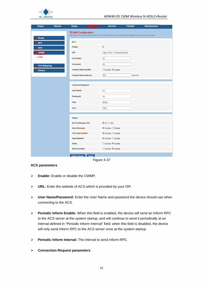
Choose “Advanced→CWMP”, you can configure the TR-069 function in the screen (shown in Figure 4-37). Here you may change the setting for the ACS’s parameters. The function supports TR-069 protocol which collects information, diagnoses the devices and configures the devices automatically via ACS (Auto-Configuration Server).
ADW40-03 150M Wireless N ADSL2+Router
52
Figure 4-37
ACS parameters Enable: Enable or disable the CWMP. URL: Enter the website of ACS which is provided by your ISP. User Name/Password: Enter the User Name and password the device should use when
connecting to the ACS. Periodic Inform Enable: When this field is enabled, the device will send an Inform RPC
to the ACS server at the system startup, and will continue to send it periodically at an interval defined in “Periodic Inform Interval” field; when this field is disabled, the device will only send Inform RPC to the ACS server once at the system startup.
Periodic Inform Interval: The interval to send Inform RPC. Connection Request parameters

ADW40-03 150M Wireless N ADSL2+Router
53
User Name/Password: Enter the User Name and Password the remote ACS should use when connecting to the device.
Path: The path of the device ConnectionRequestURL. Port: The port of the device ConnectionRequestURL. Apply Changes: Click this button to save your configurations. Reset: Click this button to delete your entering.
Note:
After configuration, you need to click the Save button appeared on the left panel so you’re your configuration can still take effect after the Router reboots.
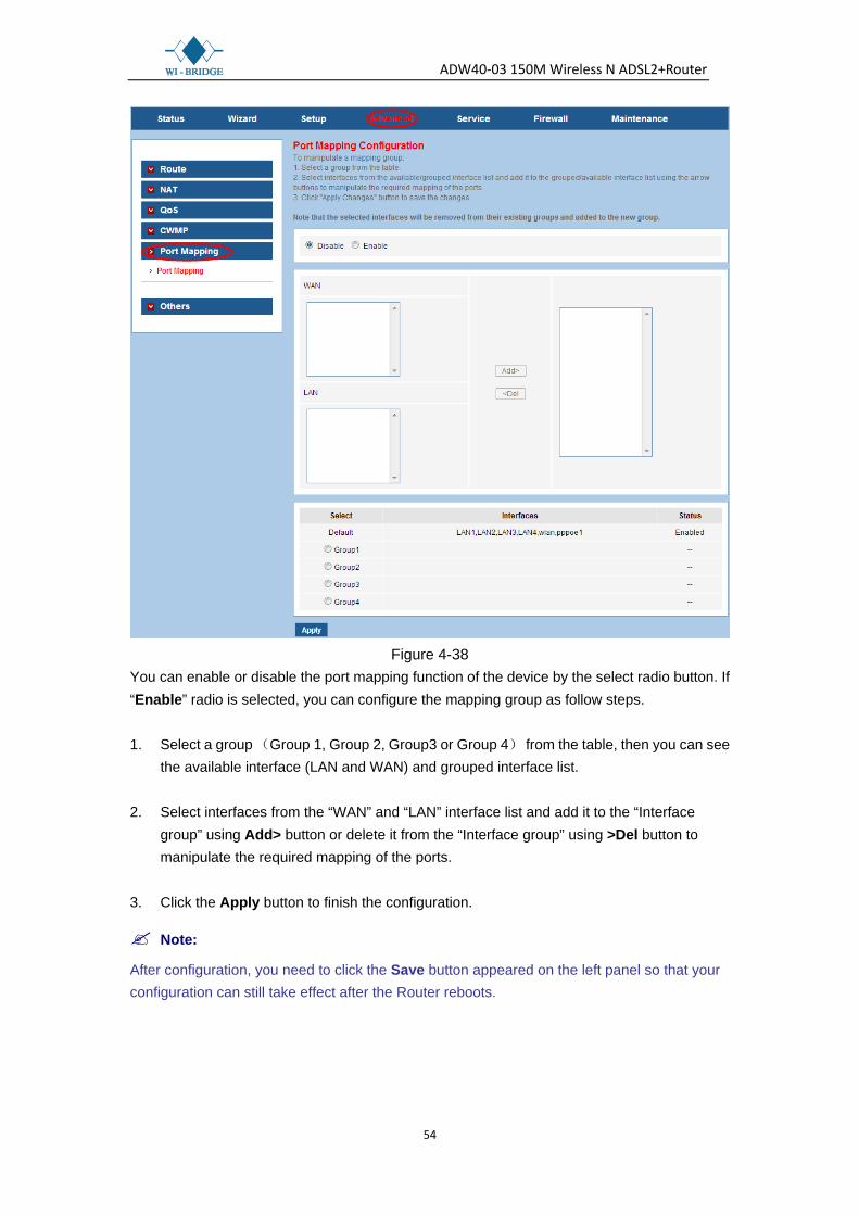
4.3.5 Port mapping
Choose “Advanced→Port Mapping”, you can configure the mapping group in the screen (shown in Figure 4-38). The device provides multiple interface groups, up to five interface groups are supported including one default group. Traffic coming from one interface of a group can only be flowed to the interfaces in the same interface group. Thus, the device can isolate traffic from group to group for some application. By default, all the interfaces (LAN and WAN) belong to the default group, and the other four groups are all empty. It is possible to assign any interface to any group but only one group.
ADW40-03 150M Wireless N ADSL2+Router
54
Figure 4-38
You can enable or disable the port mapping function of the device by the select radio button. If “Enable” radio is selected, you can configure the mapping group as follow steps. 1. Select a group (Group 1, Group 2, Group3 or Group 4) from the table, then you can see
the available interface (LAN and WAN) and grouped interface list. 2. Select interfaces from the “WAN” and “LAN” interface list and add it to the “Interface
group” using Add> button or delete it from the “Interface group” using >Del button to manipulate the required mapping of the ports.
3. Click the Apply button to finish the configuration.
Note:
After configuration, you need to click the Save button appeared on the left panel so that your configuration can still take effect after the Router reboots.

ADW40-03 150M Wireless N ADSL2+Router
55
4.3.6 Others
4.3.6.1 Bridge Setting
Choose “Advanced→Others→Bridge Setting”, you can configure the bridge setting in the screen (shown in Figure 4-39). Bridge Setting allows you to configure the bridge parameters. Here you can change the settings or view some information on the bridge and its attached ports.
Figure 4-39
Apply Changes: Click this button to save your configuration.
Undo: Click this button to cancel your configuration.
Show MACs: Click this button and then you will enter the screen as shown in Figure 4-40. This page shows some information on the bridge and its attached ports.

ADW40-03 150M Wireless N ADSL2+Router
56
Figure 4-40
4.3.6.2 Client Limit
Choose “Advanced→Others→Client Limit”, you can configure the client limit settings in the screen (shown in Figure 4-41). Client limit allows you to force how many devices can access to the internet. Here you can enable or disable the client limit function and the maximum device to access to the internet.
Figure 4-41
Client Limit Capability: Enable or disable the client limit function.

ADW40-03 150M Wireless N ADSL2+Router
57
Maximum Devices: limit the maximum number of devices that can access to the Internet.
Note:
After configuration, you need to click the Save button appeared on the left panel so that your configuration can still take effect after the Router reboots.
4.3.6.3 Tunnel
Choose “Advanced→Others→Tunnel”, you can configure the Tunnel settings in the screen (shown in Figure 4-42),This page is used to configure v6inv4 tunnel or v4inv6 tunnel.
Figure 4-42
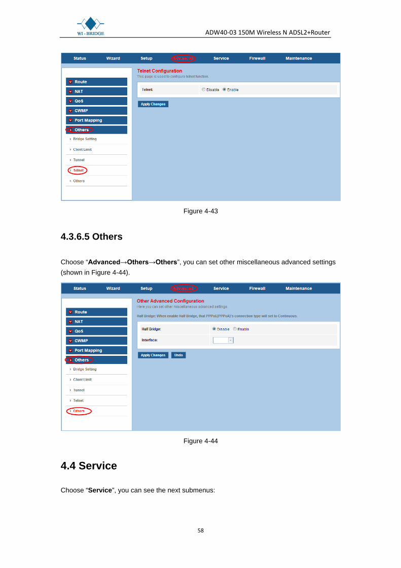
4.3.6.4 Tennel
Choose “Advanced→Others→Tennel”, you can configure the Tunnel settings in the screen (shown in Figure 4-43), This page is used to configure telnet function.
ADW40-03 150M Wireless N ADSL2+Router
58
Figure 4-43
4.3.6.5 Others
Choose “Advanced→Others→Others”, you can set other miscellaneous advanced settings (shown in Figure 4-44).
Figure 4-44
4.4 Service
Choose “Service”, you can see the next submenus:

ADW40-03 150M Wireless N ADSL2+Router
59
Click any of them, and you will be able to configure the corresponding function.
4.4.1 IGMP
4.4.1.1 IGMP proxy
Choose “Service→IGMP→ IGMP proxy” menu, you can configure the IGMP proxy in the screen (shown in Figure 4-45). Here you can enable or disable the IGMP proxy function on all WAN interface, and you can also set the parameters of the IGMP function. IP hosts use Internet Group Management Protocol (IGMP) to report their multicast group memberships to neighbor routers. Similarly, multicast routers use IGMP to discover which of their hosts belong to multicast group. The router supports IGMP proxy that handles IGMP message. When enabled, the router will act as a proxy for a LAN host making request to join and leave multicast groups, and a multicast router sending multicast packets to multicast groups on WAN side.
Figure 4-45
Note:
After configuration, you need to click the Save button appeared on the left panel so that your configuration can still take effect after the Router reboots.
ADW40-03 150M Wireless N ADSL2+Router
60
4.4.1.2 MLD
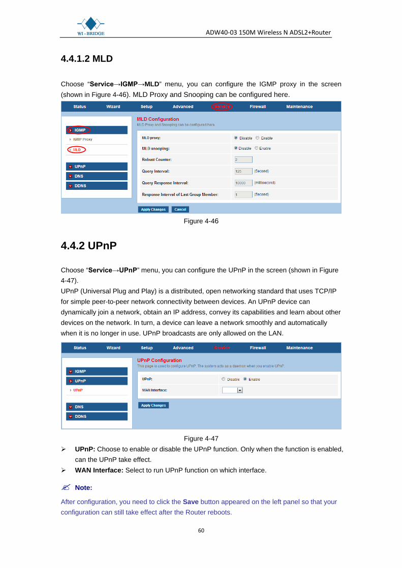
Choose “Service→IGMP→MLD” menu, you can configure the IGMP proxy in the screen (shown in Figure 4-46). MLD Proxy and Snooping can be configured here.
Figure 4-46
4.4.2 UPnP
Choose “Service→UPnP” menu, you can configure the UPnP in the screen (shown in Figure 4-47). UPnP (Universal Plug and Play) is a distributed, open networking standard that uses TCP/IP for simple peer-to-peer network connectivity between devices. An UPnP device can dynamically join a network, obtain an IP address, convey its capabilities and learn about other devices on the network. In turn, a device can leave a network smoothly and automatically when it is no longer in use. UPnP broadcasts are only allowed on the LAN.
Figure 4-47
UPnP: Choose to enable or disable the UPnP function. Only when the function is enabled, can the UPnP take effect.
WAN Interface: Select to run UPnP function on which interface.
Note:
After configuration, you need to click the Save button appeared on the left panel so that your configuration can still take effect after the Router reboots.
ADW40-03 150M Wireless N ADSL2+Router
61
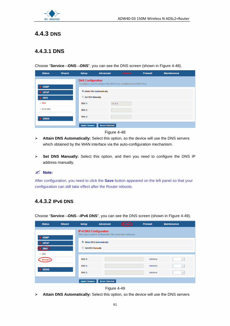
4.4.3 DNS
4.4.3.1 DNS
Choose “Service→DNS→DNS”, you can see the DNS screen (shown in Figure 4-48).
Figure 4-48
Attain DNS Automatically: Select this option, so the device will use the DNS servers which obtained by the WAN interface via the auto-configuration mechanism.
Set DNS Manually: Select this option, and then you need to configure the DNS IP address manually.
Note:
After configuration, you need to click the Save button appeared on the left panel so that your configuration can still take effect after the Router reboots.
4.4.3.2 IPv6 DNS
Choose “Service→DNS→IPv6 DNS”, you can see the DNS screen (shown in Figure 4-49).
Figure 4-49
Attain DNS Automatically: Select this option, so the device will use the DNS servers

ADW40-03 150M Wireless N ADSL2+Router
62
which obtained by the WAN interface via the auto-configuration mechanism. Set DNS Manually: Select this option, and then you need to configure the DNS IP
address manually.
Note:
After configuration, you need to click the Save button appeared on the left panel so that your configuration can still take effect after the Router reboots.
4.4.4 DDNS
Choose “Service→DDNS”, you can configure the DDNS function in the screen (shown in Figure 4-50). The router offers a Dynamic Domain Name System (DDNS) feature. The feature lets you use a static host name with a dynamic IP address. User should type the host name, user name and password assigned to your ADSL Router by your Dynamic DNS provider.
Figure 4-50
DDNS provider: There are two DDNS provider to be selected in order to register your device, DynDNS.org and TZO.
Hostname: Domain name to be registered with the DDNS server. Interface: The WAN interface over which your device will be accessed.
ADW40-03 150M Wireless N ADSL2+Router
63
Enable: Check to enable the registration account for the DDNS server. DynDns Settings: Username: Username assigned by the DDNS provider. Password: Password assigned by the DDNS provider TZO Settings: Email: Email address assigned by DDNS provider. Key: Key assigned by DDNS provider. Dynamic DDNS Table: Display the DDNS entry of this device. Click the Add button to add the DDNS entry. Click the Remove button to delete the existed DDNS entry.
Note:
After configuration, you need to click the Save button appeared on the left panel so that your configuration can still take effect after the Router reboots.
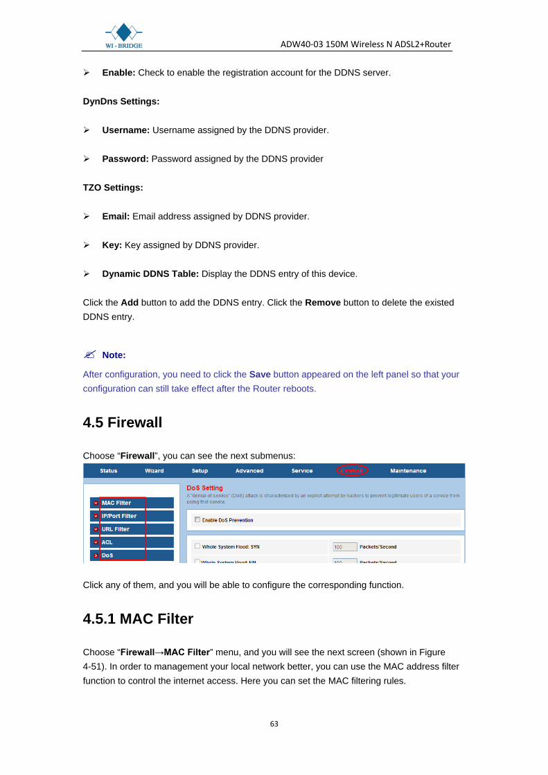
4.5 Firewall
Choose “Firewall”, you can see the next submenus:
Click any of them, and you will be able to configure the corresponding function.
4.5.1 MAC Filter
Choose “Firewall→MAC Filter” menu, and you will see the next screen (shown in Figure 4-51). In order to management your local network better, you can use the MAC address filter function to control the internet access. Here you can set the MAC filtering rules.

ADW40-03 150M Wireless N ADSL2+Router
64
Figure 4-51
Outgoing/Incoming Default Policy: The default action of outgoing/incoming connection. It can be “Deny” or “Allow”. If the connection doesn’t match any MAC filtering rules, the router will handle the connection with the default action you have set.
Direction: The direction of the filter entry, it can be “Outgoing” or “Incoming”. Action: The action of the filter entry, it can be “Deny” or “Allow”. If the action is “Deny”, the
connection matches the filter rule will be denied, if the action is “Allow”, the connection matches the filter rule will be allowed.
Source MAC: The source MAC address of the filter entry. Empty means matching any
source MAC address. Destination MAC: The destination MAC address of the filter entry. Empty means
matching any source MAC address. Add: Click this button to add your rule into “Current MAC Filter Table”. Current MAC Filter Table: It shows the current MAC filtering rules. You can delete the
entry on the list. Delete: Check the desired rule and then click this button to delete the corresponding rule. Delete All: Click this button to delete all the rules in the table.
Note:
After configuration, you need to click the Save button appeared on the left panel so that your configuration can still take effect after the Router reboots.

ADW40-03 150M Wireless N ADSL2+Router
65
4.5.2 IP/Port Filter
4.5.2.1 IP/Port Filter
Choose “Firewall→IP/Port Filter→IP/Port Filter” menu, and you will see the next screen (shown in Figure 4-52). Here you can set the IP/Port filter rules to secure or restrict your local network.
Figure 4-52
SPI Firewall: Choose to enable or disable the SPI firewall. Rule Action: The filter mode of this entry, it can be “Permit” and “Deny”. If the mode is
“Permit”, the IP connection matches the rule will be permitted; if the mode is “Deny”, the IP connection matches the rule will be denied.
Protocol: The protocol of this entry, it can be “IP”, “ICMP”, “TCP” and “UDP”. Direction: The direction of this entry, it can be “Outgoing” and “Incoming”. Source IP Address / Mask Address: The source IP address and mask address of the
entry. Dest IP Address / Mask Address: The destination IP address and mask address of the
entry.
ADW40-03 150M Wireless N ADSL2+Router
66
SPort: Tf the protocol is “TCP” or “UDP”, you should set the source port of the entry. It
can be a single port or a port range. Dport: TI the protocol is “TCP” or “UDP”, you should set the destination port of the entry.
It can be a single port or a port range. Enable: Choose to enable or disable this filter entry. Current Filter table: It shows the current filter rules. You can enable or disable or delete
the filter entry.
Note:
After configuration, you need to click the Save button appeared on the left panel so that your configuration can still take effect after the Router reboots.
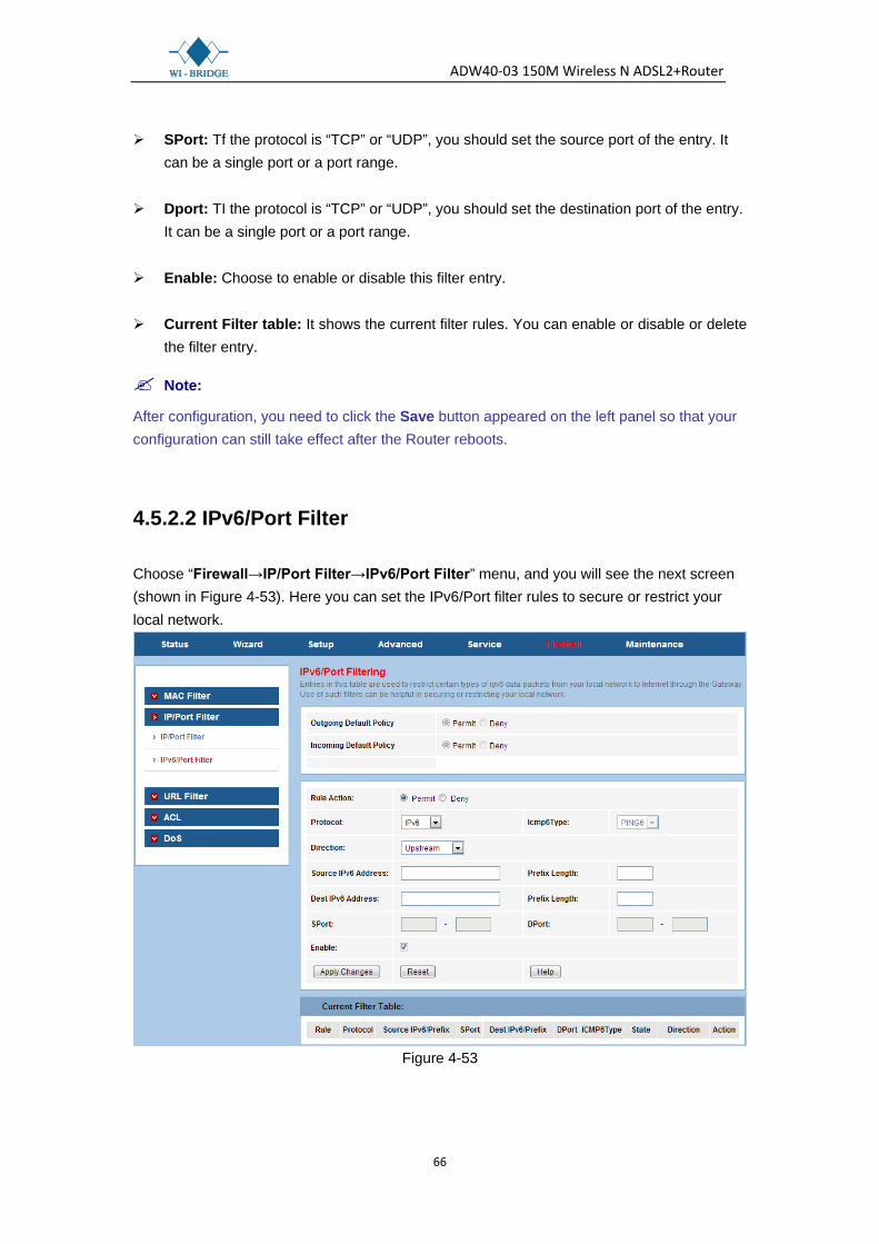
4.5.2.2 IPv6/Port Filter
Choose “Firewall→IP/Port Filter→IPv6/Port Filter” menu, and you will see the next screen (shown in Figure 4-53). Here you can set the IPv6/Port filter rules to secure or restrict your local network.
Figure 4-53

ADW40-03 150M Wireless N ADSL2+Router
67
4.5.3 URL Filter
Choose “Firewall→URL Filter” menu, and you will see the next screen (shown in Figure 4-54). Here you can specify which site can’t be accessed based on URL to secure or restrict your local network.
Figure 4-54
URL Blocking Capability: Enable or disable the URL filtering function. If it is enabled, the access to the site which matches the keyword will be blocked by the router; if it is disabled, nothing will be done.
Keyword: The keyword of the site you want to block. URL Blocking Table: It shows the current URL filtering entry. You can delete the
selected entry. For example: If you want to forbid the user to access the website including “yahoo.com”. Step 1: Select “Enable” (shown in Figure 4-56). Step 2: Enter “yahoo.com” in the Keyword field. Step 3: Finally click the AddKeyword to save the entry.
Note:
After configuration, you need to click the Save button appeared on the left panel so that your configuration can still take effect after the Router reboots.

ADW40-03 150M Wireless N ADSL2+Router
68
4.5.4 ACL
4.5.4.1 ACL
Choose “Firewall→ACL→ACL”, you can see the next screen (shown in Figure 4-55). ACL function is used to specify which services are accessible from LAN or WAN side.
Figure 4-55
Direction Select: The direction of the ACL entry, it can be LAN or WAN. 1. LAN If “LAN” is selected, you can see the next screen (shown in Figure 4-56)

ADW40-03 150M Wireless N ADSL2+Router
69
Figure 4-56
LAN ACL Switch: You can enable or disable the ACL function on LAN side. If it is
disabled, all hosts on LAN side can access the services which your router provides. If it is enabled, only the hosts on the “Current ACL Table” can access the specified services.
IP Address: The IP address of the host, “0.0.0.0” means any IP. Service Allowed (LAN side): The allowed services which the host can access. It can be
“any”, or any specified service, such as “web”, ”telnet”, ”ftp”, ”tftp”, ”snmp” and “ping”. If select “any”, it means the host can access all the services the router provides.
2. WAN If “WAN” is selected, you can see the next screen (shown in Figure 4-57)

ADW40-03 150M Wireless N ADSL2+Router
70
Figure 4-57
WAN Setting: The setting of WAN side, it can be “Interface” or “IP Address”.
If it is “Interface”, you should specify a WAN interface for this ACL entry.
If the WAN setting is “IP Address”, you should specify the IP address of the host on WAN side.

ADW40-03 150M Wireless N ADSL2+Router
71
Service Allowed: You can specify the service and opened port for this service on WAN side. The host access the specified port can obtain the specified service the router provides.
Current ACL Table: It shows the current ACL setting.
4.5.4.2 IPv6 ACL
Choose “Firewall→ACL→IPv6 ACL”, you can see the next screen (shown in Figure 4-58). ACL function is used to specify which services are accessible from LAN or WAN side.
Figure 4-58
ADW40-03 150M Wireless N ADSL2+Router
72
4.5.5 DoS
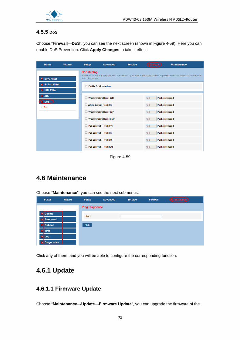
Choose “Firewall→DoS”, you can see the next screen (shown in Figure 4-59). Here you can enable DoS Prevention. Click Apply Changes to take it effect.
Figure 4-59
4.6 Maintenance
Choose “Maintenance”, you can see the next submenus:
Click any of them, and you will be able to configure the corresponding function.
4.6.1 Update
4.6.1.1 Firmware Update
Choose “Maintenance→Update→Firmware Update”, you can upgrade the firmware of the

ADW40-03 150M Wireless N ADSL2+Router
73
Router in the screen (shown in Figure 4-60). Make sure the firmware you want to use is on the local hard drive of the computer. Click Browse to find the local hard drive and locate the firmware to be used for upgrade.
Figure 4-60 To upgrade the router's firmware, follow these instructions below: Step 1: Type the exact path of the update file into the “Select File” field. Or click the Browse button to locate the update file. Step 2: Click the Upload button.
Note:
1. When you upgrade the router's firmware, you may lose its current configurations, so please back up the router’s current settings before you upgrade its firmware.
2. Do not turn off the router or press the Reset button while the firmware is being upgraded. 3. The router will reboot after the upgrading has been finished.
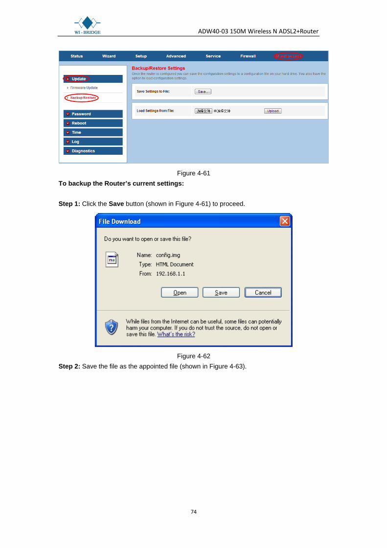
4.6.1.2 Backup/Restore
Choose “Maintenance→Update→Backup/Restore”, you can save the current configuration settings to a file, and you can also restore the settings from a configuration file (shown in Figure 4-61).
ADW40-03 150M Wireless N ADSL2+Router
74
Figure 4-61 To backup the Router’s current settings: Step 1: Click the Save button (shown in Figure 4-61) to proceed.
Figure 4-62
Step 2: Save the file as the appointed file (shown in Figure 4-63).

ADW40-03 150M Wireless N ADSL2+Router
75
Figure 4-63 To restore the Router’s settings: Step 1: Click the Browse button to locate the file for the device, or enter the exact path in “Load Settings from File” field. Step 2: Click the Upload button to complete.
4.6.2 Password
Choose “Maintenance→Password”, you can configure the user account of the router in the screen (shown in Figure 4-64). Here you can add user account to access the web server, and modify the password of the specified user.

ADW40-03 150M Wireless N ADSL2+Router
76
Figure 4-64
4.6.3 Reboot
Choose “Maintenance→Reboot”, you can select to restart the device with current settings or restore to factory default settings in the screen (shown in Figure 4-65).
Figure 4-65
4.6.4 Time
Choose “Maintenance→Time”, you can configure the system time in the screen (shown in Figure 4-66). Simple Network Timing Protocol (SNTP) is a protocol used to synchronize the system time to the public SNTP server. You can also configure the time manually.
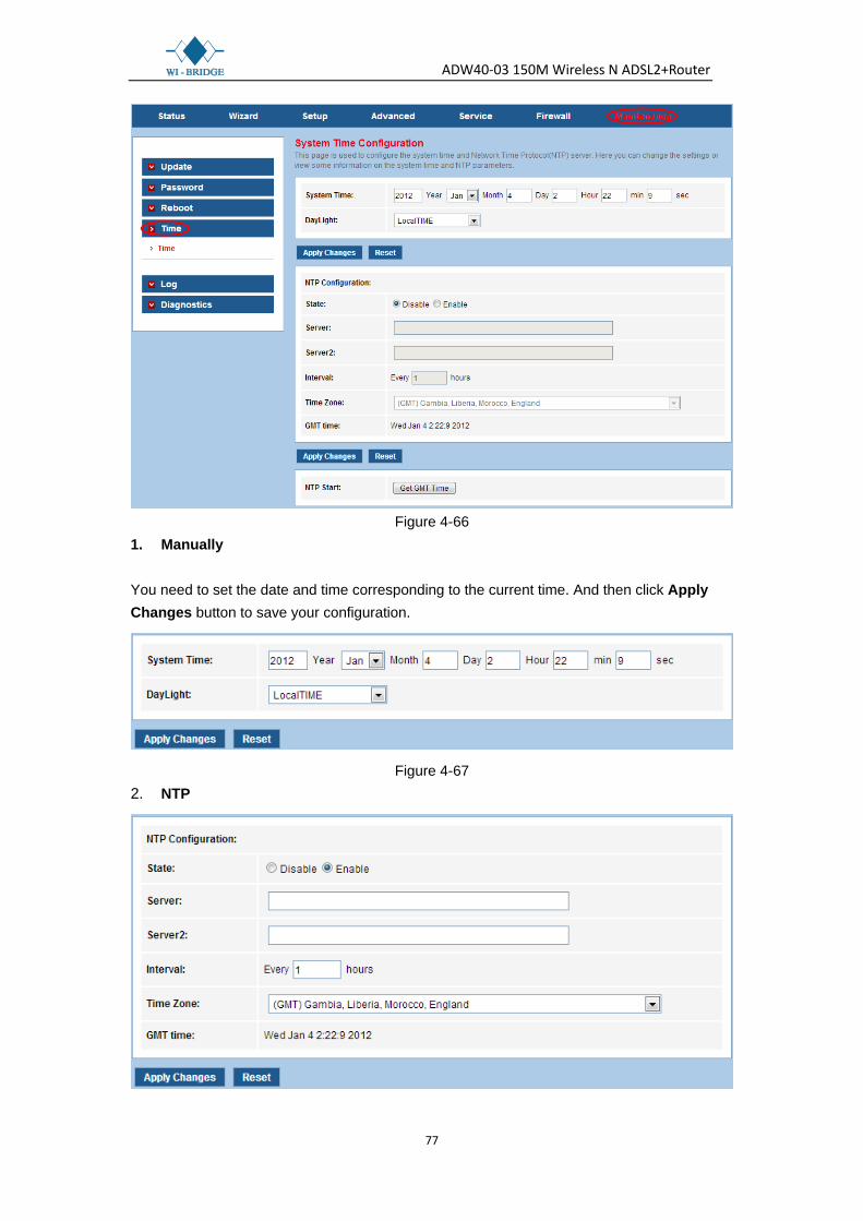
ADW40-03 150M Wireless N ADSL2+Router
77
Figure 4-66
1. Manually You need to set the date and time corresponding to the current time. And then click Apply Changes button to save your configuration.
Figure 4-67 2. NTP

ADW40-03 150M Wireless N ADSL2+Router
78
Figure 4-68 State: Indicate the current state of NTP function. Choose to enable the NTP or not.
Server/Server2: Enter the IP address or the host name of the NTP server. Interval: The interval time of NTP function. Time Zone: The time zone in which the device resides. Get GMT Time: After setting the NTP configuration correctly, click this button to start the
NTP function. Then you can see the GMT time obtained from NTP server.
Note:
If changes are made, after clicking Apply Changes button, a Save button will appear on the left panel. You need to click the Save button to make your changes take effect.
4.6.5 Log
Choose “Maintenance→Log”, you can view and configure the logs of the Modem Router (shown in Figure 4-69).
Figure 4-69
Note:
If changes are made, after clicking Apply Changes button, a Save button will appear on the left panel. You need to click the Save button to make your changes take effect.

ADW40-03 150M Wireless N ADSL2+Router
79
4.6.6 Diagnostics
The router provides several useful diagnostic tools.
4.6.6.1 Ping
Choose “Maintenance→Diagnostics→Ping”, you can ping a specified host (shown in Figure 4-70).
Figure 4-70
Host: Enter the IP address or host name you want to ping. After setting the host, click the PING button to start the ping process, then the ping result will be shown.
4.6.6.2 Ping6
Choose “Maintenance→Diagnostics→Ping6”, you can ping a specified address (shown in Figure 4-71).

ADW40-03 150M Wireless N ADSL2+Router
80
Figure 4-71 After setting the host, click the PING button to start the ping process, then the ping result will be shown.
4.6.6.3 Traceroute
Choose “Maintenance→Diagnostics→Traceroute”, you can tracert a host you want (shown in Figure 4-72). The router provides a tracert command to measure the route path and transit times of packets across an Internet Protocol (IP) network.

ADW40-03 150M Wireless N ADSL2+Router
81
Figure 4-72 Host: Enter the IP address or host name you want to run trace route command. NumberofTriers: Enter the number of try. Timeout: The time for the trace route command timeout. Datasize: Data size of the trace route packet. MaxHopCount: The maximum hop count. Interface: The interface to which the trace route is to be applied. For example, you can set the host to “www.baidu.com”, and then click the traceroute button to start the trace route process. Several times later, you can see the trace route result.
4.6.6.4 Traceroute6
Choose “Maintenance→Diagnostics→Traceroute6”, you can tracert a host you want (shown in Figure 4-73).
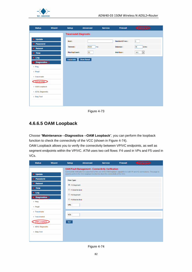
ADW40-03 150M Wireless N ADSL2+Router
82
Figure 4-73
4.6.6.5 OAM Loopback
Choose “Maintenance→Diagnostics→OAM Loopback”, you can perform the loopback function to check the connectivity of the VCC (shown in Figure 4-74). OAM Loopback allows you to verify the connectivity between VP/VC endpoints, as well as segment endpoints within the VP/VC. ATM uses two cell flows: F4 used in VPs and F5 used in VCs.
Figure 4-74

ADW40-03 150M Wireless N ADSL2+Router
83
4.6.6.6 ADSL Diagnostic
Choose “Maintenance→Diagnostics→ADSL Diagnostic”, you will see the next screen (shown in Figure 4-75). ADSL diagnostics allows you to diagnostics the ADSL tone.
Figure 4-75 Click the Start button to start the diagnostic, and then wait several minutes later you will see the test result.
4.6.6.6 Diag-Test
Choose “Maintenance→Diagnostics→Diag-Test”, you can select an interface to run diagnostic in Figure 4-76. The Diagnostic Test allows you to test your DSL connection of the physical layer and protocol layer for both LAN and WAN sides.

ADW40-03 150M Wireless N ADSL2+Router
84
Figure 4-76 Click the Run Diagnostic Test button to start the test, and then wait several times later you can see the diagnostic result.

ADW40-03 150M Wireless N ADSL2+Router
85
Appendix A: Specifications
General
Standards and Protocols ANSI T1.413, ITU G.992.1, ITU G.992.2, ITU G.992.3, ITU G.992.5, IEEE 802.11b, IEEE 802.11g, IEEE 802.11n, IEEE 802.3, IEEE 802.3u, TCP/IP, PPPoA, PPPoE, SNTP, HTTP, DHCP, ICMP, NAT
Safety & Emission FCC, CE
Ports Four 10/100M Auto-Negotiation RJ45 ports(Auto MDI/MDIX) One RJ11 port
LEDs Power, ADSL, Internet, WLAN, 1,2,3,4(LAN), WPS
Network Medium 10Base-T: UTP category 3, 4, 5 cable 100Base-TX: UTP category-5 Max line length: 6.5Km
Data Rates Downstream: Up to 24Mbps Upstream: Up to 3.5Mbps(With Annex M enabled)
System Requirement Internet Explorer 5.0 or later, Netscape Navigator 6.0 or later Win 9x/ ME/ 2000/ XP/ Vista/Windows 7
Physical and Environment
Working Temperature 0℃ ~ 40℃
Working Humidity 10% ~ 90% RH (non-condensing)
Storage Temperature -40℃ ~ 70℃
Storage Humidity 5% ~ 90% RH (non-condensing)