Embed Size (px)
Citation preview

U.S. Department
of Transportation
Federal Aviation
Administration
Advisory
Circular
Subject: Specification for Constant
Current Regulators and
Regulator Monitors
Date: 11/5/2014
Initiated by: AAS-100
AC No: 150/5345-10H
Change:
1. Purpose. This advisory circular (AC) contains a specification for constant current regulators
(CCRs) and monitors for use with airport lighting circuits.
2. Cancellations. This AC cancels AC 150/5345-10G, Specification for Constant Current
Regulators and Regulator Monitors, dated September 29, 2010.
3. Principal changes. The following principal changes are in this specification:
a. Table 1 is updated to better facilitate CCR conformance to requirements while testing.
b. Paragraph 3.3.2 is updated to state that the CCR must be operated at its maximum
intensity setting to determine efficiency.
c. Paragraph 3.3.9 is updated to delete “peak” and substitute “RMS” for CCR output
voltage.
d. Paragraph 3.3.11 adds a requirement for CCR response to zero alternating current (ac)
input power voltage glitches.
e. Paragraph 3.4.12 is updated to better define the applicability of Institute of Electrical and
Electronics Engineers (IEEE) C62.41-1991, IEEE Recommended Practice on Surge
Voltages in Low-Voltage AC Power Circuits, Location Category C3 requirements and
consistency with test requirements in paragraph 4.2.17a.
f. Paragraph 3.5i is updated to state that the monitor must delay “at least” 5.0 seconds
before a fault is displayed.
g. Paragraph 4.2.3 CCR transformer temperature rise is clarified.
h. Paragraph 4.2.6 has a note added to state that testing does not have to be performed with
the CCR at short circuit.
i. Paragraph 4.2.13 has testing additions triggered by the additional requirements in
paragraph 3.3.11.
j. Paragraph 4.2.15 has additions to clarify test conditions and procedure.

AC 150/5345-10H 11/5/2014
ii
k. Paragraph 4.2.17 is clarified for testing related to IEEE C62.41-1991 Location Category
C3.
l. Paragraph 4.2.18 is added to provide a test for the CCR overvoltage requirement in
paragraph 3.3.4c.
4. Application. The Federal Aviation Administration (FAA) recommends the guidelines and
standards in this AC for CCRs. In general, use of this AC is not mandatory. However, use of
this AC is mandatory for all projects funded with federal grant monies through the Airport
Improvement Program (AIP) and with revenue from the Passenger Facility Charges (PFC)
Program. See Grant Assistance No. 34, Policies, Standards, and Specifications, and PFC
Assurance No.9, Standards and Specifications.
5. Metric units. Throughout this AC, U.S. customary or English units are used followed with
“soft” (rounded) conversion to metric units. The English units govern.
6. Comments or suggestions. Direct comments or suggestions regarding this AC to:
Manager, Airport Engineering Division
Federal Aviation Administration
ATTN: AAS-100
800 Independence Avenue, S.W.
Washington, DC 20591
7. Copies of this AC. You can view a list of all ACs at
http://www.faa.gov/regulations_policies/advisory_circulars/. You can view the Federal Aviation
Regulations at http://www.faa.gov/regulations_policies/faa_regulations/.
Michael J. O’Donnell
Director of Airport Safety and Standards

11/5/2014 AC 150/5345-10H
iii
Table of Contents
Chapter 1. Scope and Classification. .......................................................................................... 1
1.1 Scope. ................................................................................................................................. 1 1.2 Classification...................................................................................................................... 1
Chapter 2. Referenced Documents. ............................................................................................ 3
2.1 General. .............................................................................................................................. 3 2.2 FAA advisory circulars. ..................................................................................................... 3 2.3 FAA standards. .................................................................................................................. 3 2.4 Code of Federal Regulations (CFR). ................................................................................. 3
2.5 Institute of Electrical and Electronics Engineers (IEEE) and American National
Standards Institute (ANSI) publications. ...................................................................... 3
2.6 Military standards. ............................................................................................................. 4 2.7 National Electric Manufacturers Association (NEMA). .................................................... 4 2.8 International Electrotechnical Commission (IEC). ............................................................ 4
Chapter 3. Equipment Requirements. ....................................................................................... 5
3.1 General. .............................................................................................................................. 5 3.2 Environmental requirements. ............................................................................................. 5
3.3 Performance requirements. ................................................................................................ 5 3.4 Detailed requirements. ....................................................................................................... 9 3.5 Monitor. ........................................................................................................................... 14
Chapter 4. Equipment Certification Requirements. .............................................................. 17
4.1 Certification procedures. .................................................................................................. 17 4.2 Certification testing. ......................................................................................................... 17 4.3 Output waveforms. ........................................................................................................... 23
Chapter 5. Production Test Requirements. ............................................................................. 25
5.1 Production testing. ........................................................................................................... 25
List of Tables
Table 1. CCR output current .......................................................................................................... 6 Table 2. CCR efficiency ................................................................................................................ 6
Table 3. CCR fault conditions ..................................................................................................... 15 Table 4. CCR conducted emission limits ..................................................................................... 20 Table 5. CCR radiated emission limits ........................................................................................ 21 Table 6. Test waveform amplitudes ............................................................................................. 23

AC 150/5345-10H 11/5/2014
iv
Intentionally Left Blank
11/5/2014 AC 150/5345-10H
1
Chapter 1. Scope and Classification.
1.1 Scope.
This specification details the requirements for constant current regulators (CCRs) and a monitor
system for use with airport series lighting circuits.
1.2 Classification.
1.2.1 Types.
L-827 – Regulator monitor.
L-828 – Regulator without monitoring.
L-829 – Regulator with monitoring.
Note: Multiple regulators may be bussed together into switchgear configurations, but each
regulator must meet the requirements of this specification. In addition, each regulator must have
disconnects to isolate it from primary and control power.
1.2.2 Classes.
Applicable to regulators only:
Class 1 – 6.6 amperes (A) output current.
Class 2 – 20.0 A output current (see Note 1 in paragraph 1.2.4).
1.2.3 Styles.
Applicable to regulators only:
Style 1 – three brightness steps.
Style 2 – five brightness steps.
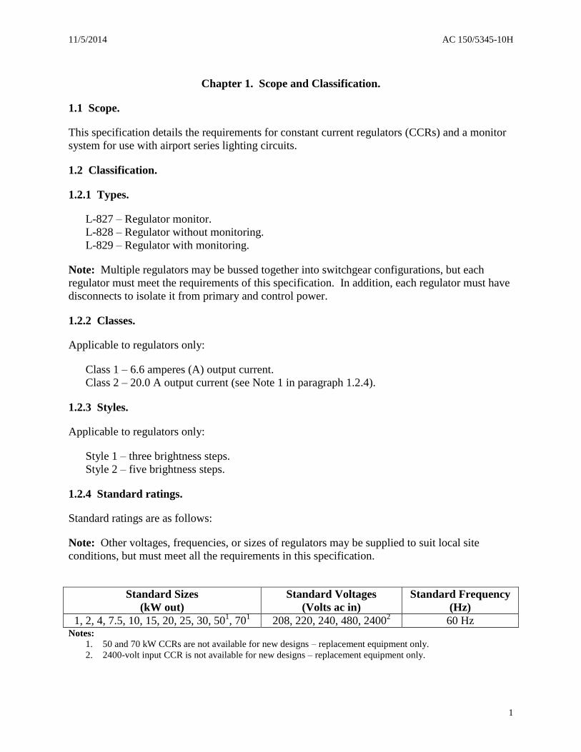
1.2.4 Standard ratings.
Standard ratings are as follows:
Note: Other voltages, frequencies, or sizes of regulators may be supplied to suit local site
conditions, but must meet all the requirements in this specification.
Standard Sizes
(kW out)
Standard Voltages
(Volts ac in)
Standard Frequency
(Hz)
1, 2, 4, 7.5, 10, 15, 20, 25, 30, 501, 70
1 208, 220, 240, 480, 2400
2 60 Hz
Notes:
1. 50 and 70 kW CCRs are not available for new designs – replacement equipment only.
2. 2400-volt input CCR is not available for new designs – replacement equipment only.

AC 150/5345-10H 11/5/2014
2
Intentionally Left Blank

11/5/2014 AC 150/5345-10H
3
Chapter 2. Referenced Documents.
2.1 General.
The following is a list of documents referenced in this AC.
2.2 FAA advisory circulars.
ACs may be obtained from www.faa.gov/airports/resources/advisory_circulars/.
AC 150/5345-47 Isolation Transformers for Airport Lighting Systems
AC 150/5345-53 Airport Lighting Equipment Certification Program
AC 150/5345-56 Specification for L-890 Airport Lighting Control and Monitoring
System (ALCMS)
2.3 FAA standards.
FAA Standards may be obtained from
http://www.faa.gov/about/office_org/headquarters_offices/ato/service_units/techops/atc_facilitie
s/cm/dcc/.
FAA-STD-019 Lightning and Surge Protection, Grounding, Bonding and
Shielding Requirements for Facilities and Electronic Equipment
2.4 Code of Federal Regulations (CFR).
CFRs may be obtained from www.ecfr.gov.
Title 47 CFR, Telecommunication
Subpart A Section 15.13, Incidental Radiators
Subpart B Section 15.107, Conducted limits
Subpart B Section 15.109, Radiated emission limits
2.5 Institute of Electrical and Electronics Engineers (IEEE) and American National
Standards Institute (ANSI) publications.
IEEE publications may be obtained from http://www.techstreet.com/ieee. ANSI publications
may be obtained from http://webstore.ansi.org/.
ANSI/IEEE C57.12.00-2000 IEEE Standard General Requirements for Liquid-Immersed
Distribution, Power, Regulating Transformers
AC 150/5345-10H 11/5/2014
4
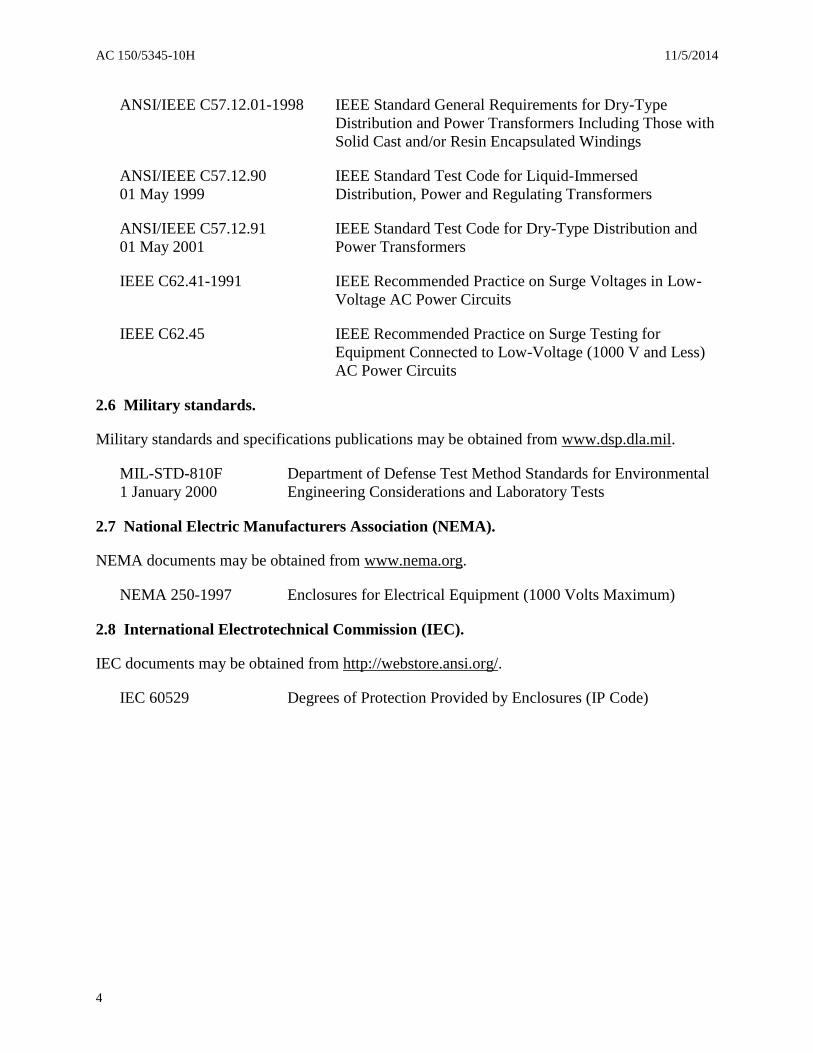
ANSI/IEEE C57.12.01-1998 IEEE Standard General Requirements for Dry-Type
Distribution and Power Transformers Including Those with
Solid Cast and/or Resin Encapsulated Windings
ANSI/IEEE C57.12.90 IEEE Standard Test Code for Liquid-Immersed
01 May 1999 Distribution, Power and Regulating Transformers
ANSI/IEEE C57.12.91 IEEE Standard Test Code for Dry-Type Distribution and
01 May 2001 Power Transformers
IEEE C62.41-1991 IEEE Recommended Practice on Surge Voltages in Low-
Voltage AC Power Circuits
IEEE C62.45 IEEE Recommended Practice on Surge Testing for
Equipment Connected to Low-Voltage (1000 V and Less)
AC Power Circuits
2.6 Military standards.
Military standards and specifications publications may be obtained from www.dsp.dla.mil.
MIL-STD-810F Department of Defense Test Method Standards for Environmental
1 January 2000 Engineering Considerations and Laboratory Tests
2.7 National Electric Manufacturers Association (NEMA).
NEMA documents may be obtained from www.nema.org.
NEMA 250-1997 Enclosures for Electrical Equipment (1000 Volts Maximum)
2.8 International Electrotechnical Commission (IEC).
IEC documents may be obtained from http://webstore.ansi.org/.
IEC 60529 Degrees of Protection Provided by Enclosures (IP Code)

11/5/2014 AC 150/5345-10H
5
Chapter 3. Equipment Requirements.
3.1 General.
The equipment requirements are grouped into four categories: environmental, performance,
detail, and monitoring.
3.2 Environmental requirements.
The equipment must be designed for continuous operation under the following conditions:
a. Temperature range is from -40° to 131° Fahrenheit (F) (-40° to 55° Celsius (C)).
b. For monitoring circuitry, the temperature range is from 32° to 131°F (0° to 55°C).
c. Relative humidity range is from 10 to 95 percent.
d. Altitude range is from zero to 6,600 feet above sea level (2,000 meters).
3.3 Performance requirements.
3.3.1 Regulation.
3.3.1.1 Resistive loading.
The CCR must maintain output currents per Table 1 while powering any load from short circuit
to 100 percent.
a. For all CCRs, regulation must be maintained over the full range of environmental
conditions specified in paragraph 3.2 and the input voltage range specified in paragraph 3.3.4.

AC 150/5345-10H 11/5/2014
6
Table 1. CCR output current
Class Style Step Nominal output
amperes (A)
root mean square
(RMS)
Allowable range
(A RMS)
1 1 3 6.6 6.50 – 6.70
2 5.5 5.40 – 5.60
1 4.8 4.70 – 4.90
1 2 5 6.6 6.50 – 6.70
4 5.2 5.10 – 5.30
3 4.1 4.00 – 4.20
2 3.4 3.30 – 3.50
1 2.8 2.70 – 2.90
2 2 5 20.0 19.70 – 20.30
4 15.8 15.50 – 16.10
3 12.4 12.10 – 12.70
2 10.3 10.00 – 10.60
1 8.5 8.20 – 8.80
3.3.1.2 Reactive loading.
The CCR output current must be per Table 1 for all current steps when the CCR is connected to
series isolation transformers with between 0 and 30 percent of the secondary windings open
circuited.
3.3.2 Efficiency.
The efficiency of a CCR operated at its maximum intensity setting, rated input voltage, with 100
percent load at unity power factor (PF) must not be less than the values shown in Table 2.
Table 2. CCR efficiency
CCR size
kilowatts (kW)
Minimum overall
Efficiency (percent)
Less than 30 90
30 92
50 93
70 94
3.3.3 Power Factor (PF).
a. The PF for CCRs 10 kW or less must not be less than 0.90.
b. The PF must not be less than 0.95 for CCRs larger than 10 kW.

11/5/2014 AC 150/5345-10H
7
c. The PF must be measured with the equipment operating at:
(1) its maximum intensity setting,
(2) its rated input voltage, and
(3) its rated load at unity PF.
3.3.4 Standard input voltage.
The CCR standard input voltage must be single phase, 60 Hz alternating current (ac).
a. All CCRs must operate per paragraph 3.3.1 when the input voltage is from 95 to 110
percent of its nominal value.
b. CCRs may be provided with different voltage taps from which the correct supply voltage
may be selected.
c. The CCR must be designed to withstand momentary increases of voltage up to 120
percent of the nominal input voltage (duration of overvoltage not longer than 50 milliseconds at
no more than once per minute) without shutdown or damage.
3.3.5 Temperature rise.
The temperature rise of the transformer portion of the CCR must not exceed the maximum
transformer safe operating temperature and the maximum insulation temperature permitted in the
hottest spot of the windings when operated at its maximum operating temperature (131°F or
55°C). Temperature rise measurements are performed at room temperature (77°F or 25°C).
3.3.6 Crest factor.
a. The crest factor for L-828 and L-829 CCRs must be less than 3.2 with regulator output
loading per paragraph 3.3.1.1.
b. Testing does not have to be accomplished when the CCR is short-circuited.
3.3.7 CCR control system.
a. The control system must stabilize the CCR output current at any selected intensity within
5.0 seconds, and hold the output current stable within ±0.1 A for 6.6 A CCRs and ±0.3 A for
20 A CCRs.
b. The control system must provide both local and remote control.
c. The equipment must function properly when operated by a circuit with a round-trip
length of 10,000 feet (3,000 m) using #19 American Wire Gauge (AWG) control cable.
d. The operating voltage for the remote control system must not exceed 120 V ac or +48 V
direct current (dc).

AC 150/5345-10H 11/5/2014
8
3.3.8 Output current surge limitation.
a. The equipment must be designed so that switching the equipment on and off, changing
brightness steps, or opening/shorting the output will not produce current surges that will
damage the CCR or any equipment connected to its output.
b. If a start-up time delay is used, no more than 2.0 seconds must elapse from CCR turn-on
to current present at the output terminals.
c. The CCR must not generate a transient of over 120 percent of the nominal current for
more than 250 milliseconds at any step or setting after the load is switched with a 50
percent resistive component. The preceding must also be true when the load includes an
inductive component at a PF of 0.6.
3.3.9 CCR circuit isolation.
a. The input power circuit must be electrically isolated from the output circuit.
b. With open circuit protection disabled, the root mean square (RMS) output voltage of an
open-circuited CCR must not exceed two times the rated wattage divided by the rated current or
4,250 volts, whichever is greater.
3.3.10 Protective devices.
3.3.10.1 Open-circuit protection.
a. The CCR must include an open-circuit protective device to open the primary switch (see
paragraph 3.4.1 for the primary switch description) within 2.0 seconds after an open circuit is
detected in the regulator output circuit.
b. The protective device must reset within 2.0 seconds after the CCR control switch is
turned off and re-energized. Alternatively, if a reset switch is provided, it may be used to reset
the protective device and re-energize the regulator.
c. The protective device must not be tripped by load circuit switching or other transients.
3.3.10.2 Over-current protection.
a. CCRs must include an over-current protective device that opens the primary switch when
the output current exceeds 100 percent (6.6 or 20 A) by 5 percent.
b. The protective device must operate within 5.0 seconds after an over-current of 5 percent
and within 1.0 second after an over-current of 25 percent.
c. The protective device must reset within 2.0 seconds after the regulator control switch is
turned off and re-energized. Alternatively, if a reset switch is provided, it may be used to reset
the protective device and re-energize the regulator.

11/5/2014 AC 150/5345-10H
9
d. The over-current protection must not be activated by momentary (0.25 second) over-
current events that are caused by load circuit switching or other transients.
3.3.11 Input power loss.
If there is a short duration loss of CCR ac input power of up to 500 milliseconds, the CCR must
resume operation (CCR is “ON” at the same current step and producing current) within one
second after the power interruption (ac input power is restored after 500 milliseconds).
3.3.12 Electromagnetic Interference (EMI).
The regulator must cause the minimum possible radiated or conducted electromagnetic
interference (EMI) to airport and FAA equipment (e.g., computers, radars, instrument landing
systems, radio receivers, very high frequency (VHF) omnidirectional range, etc.) that may be
located on or near an airport.
Note: A CCR is classified as an incidental radiator (Title 47, subpart A, section 15.13). This
applies to equipment that does not intentionally generate any radio frequency energy, but may
create such energy as an incidental part of its intended operations. A CCR must employ good
engineering practices to minimize the risk of harmful interference.
3.4 Detailed requirements.
3.4.1 Primary switch.
a. The CCR must use a primary switching device that interrupts the input power prior to the
current regulating/transformer circuits.
b. The primary switching device must be operable by remote control and must not interrupt
the regulator internal control power.
3.4.2 Operator controls.
a. The CCR must provide, located for ready access on the CCR, without opening doors or
removing covers, a means for the operator to select the remote/local modes and the desired
current step.
b. If a dedicated control switch (or an assembly of switches) is used, it must be marked:
(1) Remote, Off, 10, 30, 100 for a three step CCR.
(2) Remote, Off, 1, 2, 3, 4, 5 for a five step CCR.
c. If a rotary switch is used, it must not be allowed to rotate beyond an active position.
d. Multi-function keys or discrete switches may be used in place of, or in addition to, a
dedicated switch.

AC 150/5345-10H 11/5/2014
10
e. All controls must be designed to clearly reflect the function and status of the dedicated
switch, switches, or keypad entries per paragraph 3.4.2b.
f. The manufacturer may provide additional functions and features that enhance the
performance or serviceability of the CCR, but they must not cause any confusion with the
controls per paragraph 3.4.2b.
3.4.3 Output ammeter.
a. A flush-mounted, true RMS digital or analog meter to indicate the CCR output current
must be positioned on the front of the regulator enclosure so it may be easily read.
b. If analog, the meter must have a scale of sufficient length that allows the operator to
easily distinguish 0.1 A for a 6.6 A CCR and 0.3 A for a 20 A CCR.
c. The panel meter accuracy must be at least ±1.0 percent (at full scale with analog meter)
of the CCR maximum output current with non-sinusoidal waveforms.
3.4.4 Output voltmeter.
a. The manufacturer may offer an optional true RMS digital or analog voltmeter that is
positioned on the front of the regulator cabinet in reasonable proximity to the output ammeter
specified in paragraph 3.4.3.
b. The panel meter accuracy must be ±1.0 percent (at full scale with analog meter) of the
CCR maximum output voltage at the highest current step setting.
3.4.5 Operator display.
a. A digital multi-functional display may be used by the manufacturer to display CCR
parameters, controls, and equipment setting options. Any displayed value must clearly identify
the name of the value (for example: volts, watts, amps, or current step).
b. The display must show the CCR output current by default.
c. If an operator uses the display for purposes other than the CCR output current, the display
must revert to the output current if no keypad entries are made for more than one minute.
3.4.6 Terminal block.
a. Pressure-type terminal blocks with a suitable voltage and current rating must be installed
in the control cabinet for connection to the external wiring associated with monitoring and
remote control.
b. Terminal blocks must accommodate #12 to 20 AWG wire with insulation ratings up to
600 V.
c. The following minimum terminal functions must be made available and labeled per the
following list:

11/5/2014 AC 150/5345-10H
11
Note: The manufacturer may provide additional terminal functions and labels for CCR
monitoring and a computer interface if connected to a computerized remote control.
Terminal function Label
(1) Power supply for remote control CCI
(control power)
(2) Return from remote on/off switch CC
(3) Returns from remote intensity switch Bl-B2-B3
(3 or 5 terminals required) or Bl-B2-B3-B4-B5
(4) Input for external control power XCP
(if required)
(5) Neutral for external control power N
(if required)
3.4.7 CCR enclosure.
a. The reactors and/or transformer components must be housed in an enclosure of sheet
steel or other suitable material per NEMA equipment enclosures Type 1 (equivalent to IEC
IP20).
b. The enclosure must be equipped with a removable cover that is securely held in place.
c. Feet or channels must be attached that provide no less than 2.0 inches (5.1 cm) of space
between the bottom of the enclosure and the floor.
d. Four enclosed terminals (one pair labeled “input” and the other “output”) rated for the
proper voltage and current must be located on the top, side, or front of the enclosure.
e. Lifting lugs that are properly rated for the CCR cabinet weight must be installed on the
enclosure.
f. The overall size of a complete CCR assembly must allow it to pass through an opening
39.0 inches (1.0 meter (m)) wide by 78.0 inches (2.0 m) high.
g. A ground terminal must be provided on the outside of the CCR cabinet.
h. CCR oil-immersed transformer enclosures must allow no seepage of oil from welds,
gaskets, seals, or vents.
(1) Oil-immersed transformer enclosures must be equipped with a sampling/drain valve
located not more than 2.0 inches (5.1 cm) above the bottom of the enclosure.
(2) The CCR must have a method or device that indicates the proper transformer oil
level.

AC 150/5345-10H 11/5/2014
12
(3) The CCR must be shipped filled with the proper amount of oil and be ready for
service.
3.4.8 Control cabinet.
a. A control cabinet, or a compartment that excludes falling dirt, must be provided for
housing the relays, control terminal block, remote/local control switch, and other low voltage
control components of the CCR.
b. The control cabinet or compartment must be either permanently attached to or an integral
part of the CCR enclosure.
c. All low voltage control components must be easily accessible by opening the CCR
cabinet and/or control cabinet or compartment panels/doors. No high voltage components may
be installed in the low voltage component area or on the CCR front panel door.
3.4.9 Capacitors.
a. If PF correction capacitors are provided, the terminals must be protected from accidental
contact.
b. The service life expectancy of the capacitors must not be less than 60,000 hours under
rated operating conditions.
3.4.10 Wiring diagram.
A legible wiring diagram must be permanently mounted in an unobstructed viewing location in
the CCR control cabinet.
3.4.11 Painting and finishing.
a. The inside and outside of the enclosure must be painted with one prime coat and one
finish coat of oil-resistant and weatherproof paint.
b. Coatings with equivalent oil resistance and weatherproofing properties may be
substituted for paint.
c. Damage to the coating on the CCR enclosure must be repaired after assembly and
production testing is complete.
3.4.12 Lightning/surge arresters.
a. Arresters of the proper rating to protect the CCR from lightning-induced voltage and
current surges must be installed at both the input and output terminals of the CCR.
b. The CCR ac input power lightning arresters must be rated for pulses per IEEE C62.41-
1991, paragraph 4.2.17b, Table 6, Category B2, Medium.

11/5/2014 AC 150/5345-10H
13
c. The CCR series lighting circuit output lightning arrestors must be rated for Location
Category C3 in IEEE 62.41-1991, Table 4.
d. The ground side of the arresters must be connected to the cabinet grounding lug or other
electrically equivalent ground location. If a bonding jumper wire is used, it must not be smaller
than 14 AWG.
3.4.13 Transient voltage and current protection.
a. Transient protection that does not degrade signal quality must also be provided for all
signal, data, and control lines that enter the monitor and/or CCR per IEEE C62.41-1991, Table 3,
Category A2.
Note: See IEEE C62.41- 1991, Section 9, Definition of Standard Surge Testing Waveforms, for
detailed explanations of surge/transient waveforms.
3.4.14 Warning.
A plate or decal must be affixed to the front of the CCR control cabinet door warning the
maintenance technician to remove input and control power before opening the cabinet or
interrupting the output series circuit.
3.4.15 Components.
All CCR components must be suitable for their function and not be operated in excess of the
component manufacturer’s recommended rating.
3.4.16 Nameplate.
a. A nameplate with the following information must be securely attached to the front of the
CCR enclosure.
(1) Constant current regulator, single phase.
(2) Input: ____Volts ____Hertz ____Amperes.
(3) Control: ____Volts ____Hertz.
(4) Output: ____kW at ____Amperes.
(5) Output Current: ____Amperes ____Gallons of oil.
(6) Identification: FAA-L-828, or L-829 ____Serial No.
b. If the nameplate is attached to a removable enclosure surface (a cover), the serial number
must be duplicated in a permanent conspicuous location elsewhere on the CCR.
AC 150/5345-10H 11/5/2014
14
3.4.17 Instruction book.
An instruction book with at least the following information must be furnished with each CCR:
a. Schematic and wiring diagrams showing all components for user serviceable parts.
b. Parts list with applicable rating and characteristics of each part and with the component
manufacturer’s name and part number.
c. Installation instructions.
d. Maintenance instructions.
e. Troubleshooting charts.
f. Theory of operation.
3.5 Monitor.
The monitor must detect the status of the CCR and the series lighting circuit.
a. Type L-829 CCRs must use integral monitoring.
(1) A CCR without monitoring is designated Type L-828.
(2) A monitor may be offered as a separate module designated Type L-827.
(3) If monitoring is added to a Type L-828 regulator, it becomes a Type L-829.
b. The monitor must be matched with the CCR so it will function when the CCR is
powering a load with a nominal value that is between 50 and 100 percent of its rated capacity.
The load must be a constant current loop that energizes the primary of isolating transformers that
are specified in AC 150/5345-47, Isolation Transformers for Airport Lighting Systems. The
secondary winding of the transformers will power airport lighting fixtures.
c. At a minimum, the monitor must operate on the top two steps of Style 1 (three brightness
steps) and Style 2 (five brightness steps) regulators.
d. The monitor must detect the fault conditions in Table 3.
11/5/2014 AC 150/5345-10H
15
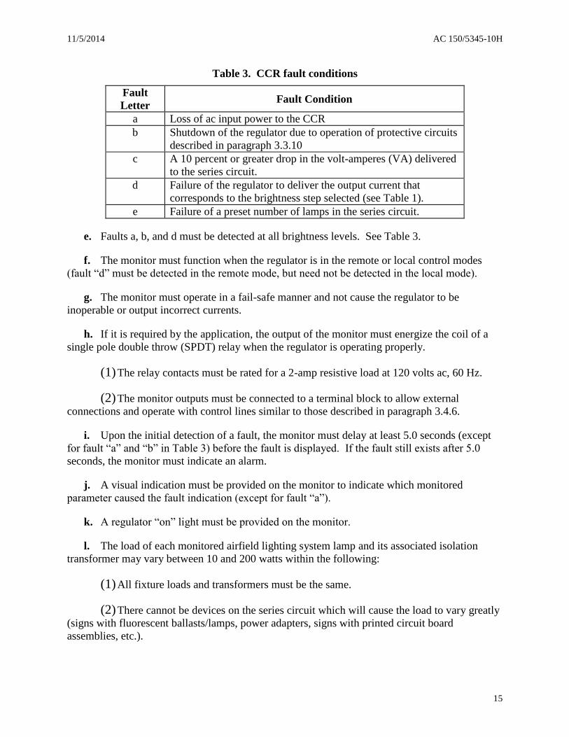
Table 3. CCR fault conditions
Fault
Letter Fault Condition
a Loss of ac input power to the CCR
b Shutdown of the regulator due to operation of protective circuits
described in paragraph 3.3.10
c A 10 percent or greater drop in the volt-amperes (VA) delivered
to the series circuit.
d Failure of the regulator to deliver the output current that
corresponds to the brightness step selected (see Table 1).
e Failure of a preset number of lamps in the series circuit.
e. Faults a, b, and d must be detected at all brightness levels. See Table 3.
f. The monitor must function when the regulator is in the remote or local control modes
(fault “d” must be detected in the remote mode, but need not be detected in the local mode).
g. The monitor must operate in a fail-safe manner and not cause the regulator to be
inoperable or output incorrect currents.
h. If it is required by the application, the output of the monitor must energize the coil of a
single pole double throw (SPDT) relay when the regulator is operating properly.
(1) The relay contacts must be rated for a 2-amp resistive load at 120 volts ac, 60 Hz.
(2) The monitor outputs must be connected to a terminal block to allow external
connections and operate with control lines similar to those described in paragraph 3.4.6.
i. Upon the initial detection of a fault, the monitor must delay at least 5.0 seconds (except
for fault “a” and “b” in Table 3) before the fault is displayed. If the fault still exists after 5.0
seconds, the monitor must indicate an alarm.
j. A visual indication must be provided on the monitor to indicate which monitored
parameter caused the fault indication (except for fault “a”).
k. A regulator “on” light must be provided on the monitor.
l. The load of each monitored airfield lighting system lamp and its associated isolation
transformer may vary between 10 and 200 watts within the following:
(1) All fixture loads and transformers must be the same.
(2) There cannot be devices on the series circuit which will cause the load to vary greatly
(signs with fluorescent ballasts/lamps, power adapters, signs with printed circuit board
assemblies, etc.).
AC 150/5345-10H 11/5/2014
16
(3) Film disc cutouts must not be used since they will cause a load different than on an
open circuit series-to-series transformer.
m. The monitor must be adjustable so the number of failed lamps required to cause a failure
indication may be from four to ten when the series loop is loaded with identical wattage lamps.
For mixed wattage bulbs on the same series loop, a loss of 10 percent or more CCR load must be
detected.
n. After the preset number of monitored lamps fail, it must be possible to switch the monitor
into a degraded operation mode.
o. When in the degraded operation mode, the monitor must deactivate the fault indication
and reactivate it upon the failure of an additional preset number of lamps (one to five).
p. Additional monitor warnings or alarm levels may be optionally provided by the
manufacturer, but are not required.
Note: When a CCR is connected to a computerized airfield lighting control monitoring system
(ALCMS), the optional monitoring points may be required for reporting remote/local status and
primary power (ac power loss to the CCR). See AC 150/5345-56, Specification for L-890
Airport Lighting Control and Monitoring System (ALCMS), for additional information.

11/5/2014 AC 150/5345-10H
17
Chapter 4. Equipment Certification Requirements.
4.1 Certification procedures.
Procedures for certifying equipment to be furnished under the Federal grant assistance program
for airports are contained in AC 150/5345-53, Airport Lighting Equipment Certification
Program.
4.2 Certification testing.
Testing must be performed on each unit submitted for certification to demonstrate compliance
with the requirements of this specification.
4.2.1 Regulation test.
a. The following tests must be performed to demonstrate compliance with paragraph 3.3.1
and Table 1.
b. Where isolation transformers and lamps are not specifically required, a resistive load may
be used.
4.2.1.1 Input voltage tests.
a. For each CCR, load the output to 100 percent resistive, short circuit, and 50 percent
resistive load connected to nominal voltage; 110 percent of nominal voltage, and 95 percent of
nominal voltage.
b. Verify the CCR output current is per Table 1 for all brightness steps.
4.2.1.2 Reactive load tests.
a. An equivalent of a 100 and 50 percent reactive load (30 percent of the isolating
transformers secondary windings open-circuited) must be placed on the CCR output.
b. The CCR input voltages must be: nominal, 110 percent of nominal, and 95 percent of
nominal.
c. The CCR output current must be checked at all brightness settings and be within the
limits per Table 1 for all voltages in paragraph 4.2.1.2b above.
Note: CCR taps (if present in the CCR design) may be set to be optimized for this test per
procedures in the manufacturer’s instruction book.
4.2.2 Remote control test.
Check the output current at all brightness steps for the following remote control circuits (an
equivalent resistive load may be used to simulate the full cable lengths specified) and rated
output load:

AC 150/5345-10H 11/5/2014
18
a. Connect the remote switch via simulated 100-foot (30 m) lengths of 12 AWG wire (a
resistance equal to 0.16 ohms per wire).
b. Operate the CCR remotely on all brightness steps to determine compliance with
paragraph 3.3.7.
c. Connect the remote switch via simulated 10,000-foot (3,000 m) lengths (total round-trip
distance) of 19 AWG control wire (a resistance equal to 87 ohms per 10,000 feet of wire and a
capacitance between conductors of 0.16 microfarads).
d. Operate the CCR remotely on all brightness steps to determine compliance with
paragraph 3.3.7.
4.2.3 Temperature rise.
a. For the equipment under test, use the temperature rise results of the CCR transforming
device to determine if its maximum operating temperature at the maximum specified ambient
temperature will exceed the manufacturer’s ratings. See paragraph 3.3.5.
b. Use the resistance method at ambient room temperature (77°F or 25°C) for testing the
transformer temperature rise for both immersion and dry-type regulating transformers:
(1) For guidance in determining and testing the temperature rise of liquid-immersed
transformers, see ANSI/IEEE C57-12.90-1999, IEEE Standard Test Code for Liquid-Immersed
Distribution, Power, and Regulating Transformers, Section 11, Temperature Rise.
(2) For guidance in determining and testing the temperature rise of dry-type transformers,
see ANSI/IEEE C57.12.91-2001, IEEE Standard Test Code for Dry-Type Distribution and
Power Transformers, Section 11, Temperature Test.
4.2.4 Efficiency.
Power the equipment under test with nominal input voltage with a 100 percent load at unity
power factor. Determine the CCR efficiency at its maximum current step setting is not less than
the values per Table 2.
Note: η = P2/P1
where:
η = efficiency
P2 = active output power
P1 = active input power
4.2.5 Power factor.
For the equipment under test, apply power at the nominal input voltage with a 100 percent
resistive load. Determine that the CCR power factor at the maximum current step setting is not
less than specified in paragraph 3.3.3.

11/5/2014 AC 150/5345-10H
19
Note: PF = P
S
where:
PF = power factor
P = total input power expressed in watts (W)
S = apparent input power expressed in volt-amps (VA)
4.2.6 Crest factor.
For the equipment under test, determine the crest factor for L-828 and L-829 CCRs using the
loading per paragraph 3.3.1.1.
Note: Testing does not have to be performed with the CCR at short circuit.
a. The maximum crest factor must not exceed 3.2 at nominal input voltage for all current
step settings.
b. Crest Factor = IOUT PK
IOUT RMS
c. An oscilloscope with a suitable current probe may be required to measure the CCR peak
output current (IOUT).
4.2.7 Altitude.
a. Each design of CCR must be tested for low pressure (altitude) in accordance with MIL-
STD-810F, Method 500.4, Paragraph 4.5.3, Procedure II.
b. The maximum altitude must be 6,600 feet (2,000 meters).
c. The maximum chamber ambient air temperature must be 131°F (55°C).
d. The CCR must be operated at its rated voltage, load, and maximum brightness for one
hour.
e. Perform CCR testing per paragraph 4.2.1.1 immediately after the one hour run-in period.
f. Any test failures will be cause for rejection of the equipment.
4.2.8 Low temperature.
a. Each type of CCR must be tested by placing it in a test chamber and maintaining the
temperature at -40°F ±9°F (-40°C ±5°C) for 12 hours with the unit under test turned off.
b. Perform CCR input voltage tests per paragraph 4.2.1.1 while maintaining low
temperature. Remote control may be used.
c. The low temperature test must be run at 32°F (0°C) for L-827 monitors.

AC 150/5345-10H 11/5/2014
20
d. Verify all visual displays are functioning properly at the end of the test.
e. The failure of tests will be cause for disapproval of the regulator.
4.2.9 Humidity.
a. Each design of CCR must be tested for resistance to humidity per MIL-STD-810F,
Method 507.4, Paragraph 4.5.2, Procedure.
b. The regulator must be exposed to a minimum of five 48-hour cycles.
Note: Limit the maximum chamber temperature to 131°F (55°C) during humidity cycling.
c. After humidity cycling, perform the CCR input voltage tests per paragraph 4.2.1.1.
d. Failure of tests or evidence of corrosion or deterioration, will be cause for disapproval of
the regulator.
4.2.10 Electromagnetic interference tests.
All tests must be conducted with the CCR set to its highest output current setting at full load.
a. CCRs must be tested for and not exceed the conducted power line emissions per Title 47,
subpart B, section 15.107b, using a 50 microhenry (μH)/50 ohm line impedance stabilization
network (LISN) to the following limits in Table 4:
Table 4. CCR conducted emission limits
Frequency of
Emission
(MHz)
Quasi-peak
Emissions
Decibels per
microvolt
dB/μV
Average Emissions
dB/μV
0.15 – 0.5 79 66
0.5 –30.0 73 60
b. CCRs must be subjected to the tests in paragraph 4.2.10a and not exceed additional
testing to radiated emission limits per Title 47, subpart B, section 15.109b, for the following
limits (see Table 5) at 33 feet (10 meters):
11/5/2014 AC 150/5345-10H
21
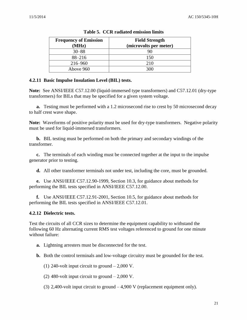
Table 5. CCR radiated emission limits
Frequency of Emission
(MHz)
Field Strength
(microvolts per meter)
30–88 90
88–216 150
216–960 210
Above 960 300
4.2.11 Basic Impulse Insulation Level (BIL) tests.
Note: See ANSI/IEEE C57.12.00 (liquid-immersed type transformers) and C57.12.01 (dry-type
transformers) for BILs that may be specified for a given system voltage.
a. Testing must be performed with a 1.2 microsecond rise to crest by 50 microsecond decay
to half crest wave shape.
Note: Waveforms of positive polarity must be used for dry-type transformers. Negative polarity
must be used for liquid-immersed transformers.
b. BIL testing must be performed on both the primary and secondary windings of the
transformer.
c. The terminals of each winding must be connected together at the input to the impulse
generator prior to testing.
d. All other transformer terminals not under test, including the core, must be grounded.
e. Use ANSI/IEEE C57.12.90-1999, Section 10.3, for guidance about methods for
performing the BIL tests specified in ANSI/IEEE C57.12.00.
f. Use ANSI/IEEE C57.12.91-2001, Section 10.5, for guidance about methods for
performing the BIL tests specified in ANSI/IEEE C57.12.01.
4.2.12 Dielectric tests.
Test the circuits of all CCR sizes to determine the equipment capability to withstand the
following 60 Hz alternating current RMS test voltages referenced to ground for one minute
without failure:
a. Lightning arresters must be disconnected for the test.
b. Both the control terminals and low-voltage circuitry must be grounded for the test.
(1) 240-volt input circuit to ground – 2,000 V.
(2) 480-volt input circuit to ground – 2,000 V.
(3) 2,400-volt input circuit to ground – 4,900 V (replacement equipment only).

AC 150/5345-10H 11/5/2014
22
(4) 120-volt control circuits to ground – 1,000 V.
(5) 48-volt control circuits to ground – 500 V.
(6) Output circuit to ground – five times the 100 percent load RMS voltage.
4.2.13 Protective device tests.
a. Test all protective devices for proper operation per paragraph 3.3.10.
b. Test the CCR open-circuit voltage per paragraph 3.3.10 using an oscilloscope or high
voltage peak reading voltmeter.
c. On each brightness step, interrupt the input voltage to the CCR for the following
durations: 10 milliseconds, 100 milliseconds, 500 milliseconds, one second, and five seconds.
Record the CCR’s response to each power interruption to confirm compliance with paragraph
3.3.11. The input current and voltage waveforms must be recorded for each interruption.
4.2.14 Leakage test.
a. Test each oil-filled regulator assembly to ensure that there is no leakage from welds,
gaskets, O-rings, or other types of seals.
b. Pressurize the unit under test with dry air to an internal air pressure of 10 ±2 pounds per
square inch gauge (PSIG) for five minutes – no loss of pressure is allowed for the test duration.
4.2.15 Output current surge.
a. Check for the compliance of the CCR output current during turn-on and switching per
paragraph 3.3.8.
b. The over-current events that occur during this test that are less than 250 milliseconds
must not activate the over-current protection, per paragraph 3.3.10.2d.
Note: Due to the operating characteristics of a circuit selector switch, the switching is back and
forth between a short and a 50 percent resistive load. The same is done for a reactive load.
4.2.16 Monitor test.
a. The manufacturer must develop a test plan and procedures for submission to the FAA,
Office of Airport Safety and Standards, Airport Engineering Division, AAS-100, or an FAA-
approved third party certification body, that demonstrates compliance with paragraphs 4.2.7
through 4.2.10 and 4.2.17.
b. The test procedure must exercise and test the monitoring functions and meet the
sensitivity requirements per paragraph 3.5.
c. The test setup must use a constant current loop with isolating transformers and lamp
loads that are at least 50 percent of the CCR’s rated capacity.
11/5/2014 AC 150/5345-10H
23
d. Monitor operation must be demonstrated with each type of CCR with which it will be
mated.
4.2.17 Surge suppression.
Note: The equipment might be damaged by the following tests; perform them only after all
other testing is complete.
a. To demonstrate the effectiveness of the CCR series lighting circuit output lightning
arrestors, they must safely suppress a test pulse per IEEE C62.41, Table 4, Location Category
C3.
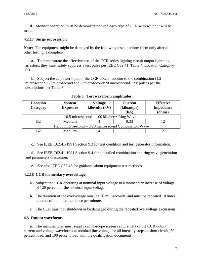
b. Subject the ac power input of the CCR and/or monitor to the combination (1.2
microsecond /50 microsecond and 8 microsecond/20 microsecond) test pulses per the
descriptions per Table 6:
Table 6. Test waveform amplitudes
Location
Category
System
Exposure
Voltage
kilovolts (kV)
Current
(kiloamps)
(kA)
Effective
Impedance
(ohms)
0.5 microsecond – 100 kilohertz Ring Wave
B2 Medium 4 0.33 12
1.2/50 microsecond – 8/20 microsecond Combination Wave
B2 Medium 4 2 2
c. See IEEE C62.41-1991 Section 9.3 for test condition and test generator information.
d. See IEEE C62.41-1991 Section 9.4 for a detailed combination and ring wave generation
and parameters discussion.
e. See also IEEE C62.45 for guidance about equipment test methods.
4.2.18 CCR momentary overvoltage.
a. Subject the CCR operating at nominal input voltage to a momentary increase of voltage
of 120 percent of the nominal input voltage.
b. The duration of the overvoltage must be 50 milliseconds, and must be repeated 10 times
at a rate of no more than once per minute.
c. The CCR must not shutdown or be damaged during the repeated overvoltage excursions.
4.3 Output waveforms.
a. The manufacturer must supply oscilloscope screen capture data of the CCR output
current and voltage waveforms at nominal line voltage for all intensity steps at short circuit, 50
percent load, and 100 percent load with the qualification documents.

AC 150/5345-10H 11/5/2014
24
Note: Oscilloscope screen capture data may be a photograph or digital file such as: bitmap
(BMP), Joint Photographic Experts Group (JPEG), or Tagged Image File Format (TIFF).
b. The 100 percent load and 50 percent half-load waveforms must be recorded with a purely
resistive load, then repeated with 30 percent of the isolation transformers open-circuited per
paragraph 4.2.1.2.
c. All waveform capture data must include the amplitudes of voltages/currents and their
duration.
d. The waveforms will be used by lighting equipment manufacturers to ensure compatibility
with all approved CCRs.
e. The waveforms must also be made available in either a manual or a standard electronic
format for a nominal fee.

11/5/2014 AC 150/5345-10H
25
Chapter 5. Production Test Requirements.
5.1 Production testing.
a. Each CCR must be tested per the requirements in paragraphs 4.2.2, 4.2.12, 4.2.13 (only
protective devices test), and 4.2.14.
b. The manufacturer must exercise and test each monitor alarm function per Table 3.

AC 150/5345-10H 11/5/2014
26
Intentionally Left Blank