Embed Size (px)
Citation preview
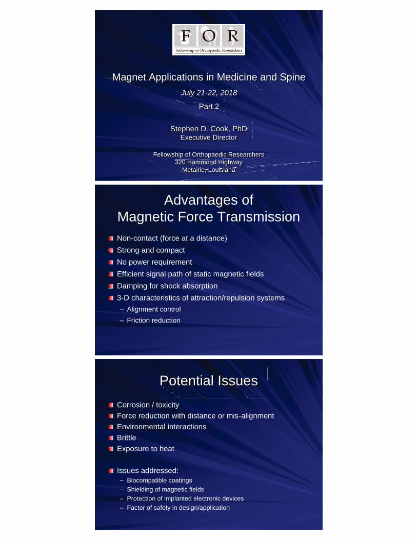
Magnet Applications in Medicine and Spine July 21212121-111--22, 2018
Part 2
Stephen D. Cook, PhDtephen D. Cook,ok, PhExecutive Director
Fellowship of Orthopaedic Researcherswship of Orthopaedic Resear320 Hammond HighwayHammond Highway20 Hammond Hi
Metairie, Louisiana
Advantages ofMagnetic Force TransmissionNon-contact (force at a distance)Strong and compactNo power requirementEfficient signal path of static magnetic fieldsDamping for shock absorption3-D characteristics of attraction/repulsion systems– Alignment control– Friction reduction
Potential IssuesCorrosion / toxicityForce reduction with distance or mis-alignmentEnvironmental interactionsBrittleExposure to heat
Issues addressed:– Biocompatible coatings– Shielding of magnetic fields– Protection of implanted electronic devices– Factor of safety in design/application
Pectus Excavatum– Magnetic Mininnn -ninini-Mover Procedure (3MP)gg (
Developed at UCSF Pediatric Surgery
Early Onset Scoliosis–
yyMagnetically controlled growing rods (MCGR)
Current Use of Magnets in the Spine
Courtesy of NuVasive
Phenix Rod™Phen(Arnaud
nix Rodhendd Soubeiran
odan, PhD;(Arnaudd oubeiraraSo aan PhD;,, P
French designer and developer)
MAGneticc Expansion ControlGneticGn ccc ansion Con ConExpanE(MAGEC) System
((NuVasiveGEAG(MMAGM
ee SpecialisedEC) SysEC) SystemGEE
dd Orthopaedicsmmem
cscscs, San Diego, CA)
Pectus ExcavatumMagnetic Mini-Mover Procedure (3MP)
– Internal magnet implanted on sternum– External magnet in anterior chest wall brace– Magnetic forces used to move the sternum
forward over time
Phase 1 IDE pilot safety trial– 10 patients, ages 8-14 years, severe PSI>3.5– No detectable ill effects– Pectus severity index improved in early and
mid-puberty patients– Weld failures of device (3/10, 30%)
Multi-center safety & efficacy trial– 15 patients, 24-months treatment– Mixed efficacy based on Haller Index– Good satisfaction at one year– Device breakage, cables (7/15, 47%)
Magnetic Mini-Mover Procedure for Pectus Excavatum, I, II, III, IVHarrison MR et al (2007, 2010, 2012) and Graves et al (2017) J. Pediatric Surg
MagnimplantNdFeB, Ti-encasedØ1.5cm x 0.48 cm thick
1st GenerationThreaded stem to back plate
Prone to weld failures
2nd GenerationTitanium cables wrap around sternum – connect magnet and back plate
Magnetic Mini-Mover Procedure (3MP)
Early Onset ScoliosisMagnetically controlled growing rods (MCGR)
– Expandable growing rod for children– Works only on the area of deformity– Rod is expanded externally with a magnet– Obtain and maintain correction as the child grows
Phenix Rod™
– 2005 1st implantations Europe– FDA approval on compassionate grounds (70
worldwide implanted)– 2012 1st two cases in USA reported by Wick & Konze
(AORN Journal)
MAGEC System (NuVasive)– 2009 CE Mark– 2012 Earliest results (Cheung et al, Lancet)– March 2014 FDA 510k approval– Safe and effective alternative to traditional growth rods– Reduced number of planned surgeries– Complications: failure of distraction, implant fracture,
metallosis
Wick & Konze, AORN Journal 2012
Phenix Rod™
Postop AP
MAGEC System

Magnet TechnologyMagnet TechnologyM ecech o oggn l yFOR Applications in the Spine
Spinous process, stenosisCervical traction“Dynamic” stabilized fusion– Adjacent segment protection
Deformity correction, scoliosisDisc replacement– Non-contacting– Contacting
Rare Earth MagnetsNeodymium-Iron-Boronnn ((NdFeBB) alloy
Offers the highest st st BBr and dd d HHHHHcicici values
Strongest magnet available e –– up to 52 2 2 MGOe
Susceptible to oxidation due to high iron content
Use in environments up to 200000000°000°C
JMAGG-G-Designer:JMAGAGG esignereesign r:eDDElectromagnetic Simulation Software
Geometry Modeling
• Geometry Editor• CAD Link to SolidWorks
Material Modeling
• Material Database• Custom Properties
Mesh Modeling
• Automatic & Adaptive Meshes• Layered & Thin Plate Meshes
Results
• Force & Torque• Magnetic Field Analysis• Contour, Vector & Flux Line Plots
High-speed, high-precision 3D FEA software used to simulate and optimize outputs of various implant and magnet configurations
JMAGG-G-Designer (r (r (Powersyss Solutions, Southfield, MI)

Validation of FEA ResultsResesdation of FEA RFFEAo RMechanical Testing
Servohydraulic test systems used to measure repulsion forces of magnet configurations and evaluate strength/duration of magnetic implants
Lumbar Spinal StenosisInterspinous Process Decompression
– Relieve symptoms of lumbar spinal stenosis– Minimally invasive procedure– Alternative to decompression spine surgery,
such as laminectomy
Coflexex(Paradigm Spinee) Superionn ((Vertiflexex)
Interspinous Process (ISP) Devices or Spacers– Implanted between spinous processes to distract or
decompress the spine at the level of stenosis– Static (non-compressible) or dynamic (compressible)– Over 65 ISP devices currently in the market
Magnetically Levitatedtatedatenetically Levitllyy LevMagnne it edSpinous Process Implant
– Repulsion forces of magnets distract and separate vertebral bodies
– Magnetic distraction increases foraminal height and alleviates nerve root impingement and pain
– Magnetic force increases as distance between magnets shortens
– “Dynamic” decompression
Magnetic Repulsion
Force
Concept – Rare earth magnets inserted between adjacent lumbar spinous processes
Magnetically Levitated ISP Device gnetically Levitated ISP Devggnet itated SP ly IS DevvDesign Concepts and Modeling
CAD design ideas in SolidWorks– Solid models– Export models to FEA software, JMAG
Model using anatomical dimensions and magnet material properties
– N52 grade NdFeB magnets– Disc shape, thickness (~3-5mm)– Separation distances
Magnetic FEA modeling (JMAG)– Force and magnetic flux density results– Repulsion force (N) using various magnet
diameters, separation distances and magnet thicknesses
– Determine target distraction loads on spinous process 0
510152025303540
0 5 10 15
Forc
e (N
)
Magnet Separation Distance (mm)
Spinous Process Implant Repulsion Force
101520
Magnet Diameter
Cervical Pain / TractionCervical Spine Injury or Neck Pain
– Degenerative changes affecting disc, facet joints, or ligaments of spine
– Symptoms include pain, headaches, stiffness, changes in neck ROM or gait, muscle weakness, or tingling sensations
Cervical Traction or Manipulation– Nonsurgical treatment option: (1) discogenic pain; (2) degenerative disc disease;
(3) radiculopathies; (4) facet joint syndrome; (5) joint hypomobility; (6) muscle spasms; (7) foraminal stenosis; and (8) post-laminectomy syndromes
– Pneumatic neck pillows, over-door traction at home– Cervical manipulation/traction therapy
Traction Load and and ndction L ad aLLoad Tracac aIntradiscal Pressures
Manual Cervical Traction– Start 8 to 10 lbf, increase by 5-lbf intervals– ~25 to 40 lbf, not to exceed 45 lbf– Ideal effect, ~7-10% BW– Sustained or Intermittent, 15 to 20 min intervals– Daily, twice daily, 2-3 times weekly
Effects of Traction on Intradiscal Pressure (IDP)––
– 10 pound traction load, IDP reduced by 14% to 28%
IDP Change per Pound of Traction (kPa/lb)
Cripton et al. (2001) 16.7
Wu et al. (2012) 1.6 – 1.9
Gudavalli et al. (2013) 1.6 – 7.2
Relative decreases in Intradiscal Pressure with applied traction forces

Magnetic Implant Technology: c Implant Techntt TecIm hSpinal Traction
Continuous Low Force Traction = Intermittent High Force Traction
Spinal Traction via
Magnetic Suspension
Targeted
Low ForceContinuous
Potential BenefitsDisc Height PreservationMinimal Tissue DisruptionPain Relief
Internal Magnetic Traction Deviceion on agnetic Tractc c Tractnal Mana ag tio Defor the Cervical Spine
– Titanium implant or screws encapsulate magnets
– Opposing repulsive magnetic fields provide distraction forces across spine segment
– Sustained magnetic separation results in foraminal distraction, relief of any disc bulge, and alleviation of nerve root pressure thus reducing pain
– Magnetic forces increase as distance between magnets shortens
– “Dynamic” levitation or internal traction
Concept – Array of rare earth magnets placed in cervical vertebrae to produce vertical distraction force across the disc
Internal Magnetic Traction Device on Don gnetic Tractic Tractal Maag io DScrew Design Features
Array of 4 Magnetic Screws– Screw: Ø 5–6 mm X 16–25 mm length– Magnet: Ø 3–5 mm X 10–20 mm length– Superior screws 8 to 12 mm apart– Inferior screws 10 to 20 mm apart– Diametrically magnetized
Design Features– Typical cervical screw system– Ti-6Al-4V alloy body– Hex/torx drive mechanism– Flat edge feature to orient magnet pole– Magnet fully encased, tip welded
8-12mm
10-20mm
8-12mm
Magnetic North Pole Direction
Pole orientation indicator Encasement Screw
Magnet
Flat edge feature
Magnetic Repulsion
Force

Internal Magnetic Traction Device on Devon gnetic Tractic Tracternal Maerna ag io DevvFEA Modeling of Magnetic Flux
Magnetic flux density on magnet surfaces
Magnetic flux density within air space Vector plot of magnetic flux
FEA mesh on magnet surfaces
Magnetic Cervical Traction, 5N separation force (range, 2 to 10N)
Magnetic Traction Model
– Attraction forces stabilize vertebrae across fusion site
– “Dynamic” compression– Expandable to multiple levels – SMF may promote bone growth
and enhance fusion mass– Repulsion forces at adjacent
non-fused segments
Concept – Rare earth magnets in an anterior plate and screw fusion system to generate a compressive force across the fusion site
Magnetic Attraction
Force
Magnetic Repulsion
Magnetic Plate and Screw System c Plate and Screwndd Scr wPla e“Dynamic” Fusion
Magnetic Plate and Screw System Plate and Screwndd Scr wPla eDesign Features
Magnetic Screws– Screw: Ø 4–5 mm X 16–25 mm length– Magnet: Ø 3–4 mm X 10–20 mm length– Diametrically magnetized– Magnet fully encased, tip welded– Pole orientation indicator
Plate Design Features– Typical anterior plate system– Contouring profile to vertebral body– Single plate: 2 or 4 screw holes– Multi-level plate– Round or oval screw holes to allow
sliding of screw within plate– Provide compression to interbody
implant and/or bone graft material
Pole orientation indicator Encasement Screw
Magnet
Flat edge feature
Magnetic Attraction
Magnetic Repulsion
Magnetic Repulsion
Oval screw hole
Prototype Magnetic Plate Prototype Magnetic Plate Proand Screws for Testing

Magnetic Plate and Screw System ew Systw ate and Screndd Scrgnetic Plggnet Pla e SystFEA Modeling of Magnetic Flux
Magnetic flux density for 4, 6 or 8 magnet configurations
0.0
0.1
0.2
0.3
0.4
0.5
0.6
0.7
12 14 16 18 20
Forc
e (N
)
Separation Distance (mm)
Compression Force* between 4 Plate Magnets
4 Magnets
6 Magnets
8 Magnets
Magnetic Plate and Screw System– Compression force doubles from 4
magnet to 8 magnet configuration
– Larger forces possible as magnet diameter increases
– Magnetic force increases as separation distance decreases
– Repulsion forceseses^ generated at adjacent non-fused segments both cranial and caudal to fusion site
**
**Compression Force
^Repulsion Force
^ ^
^
Early Onset Scoliosis (EOS)Defined as a curvature of the spine greater than 10 greater thathaan 1Defined as a curvature of the spinea curvature of thDe e gdegrees in children from birth to 10 years of ageygHigh risk of spinal deformity progression–g p yp
Chest cavity malformation–
yyHeart problems and impaired lung growth
–p g gpp
Thoracic insufficiency syndrome (TIS)Nonon-
y yyn-surgical treatments
–g
Observation– Bracing / Castingg g
Surgical procedures–
g pDistractionononon-nnn--based implantspp
Magnetically controlled growing rods (MCGR), i.e. MAGEC System
–gg y g
Guided growth implants–
gCompressiononon-
pnn-based implants
–p
Fusion
– Magnets housed in locking mechanism attached to head of pedicle screws
– Magnetic screws placed in pedicles at level of curve, above and below
– Attraction forces stabilize vertebrae across levels of spine
– Magnet poles oriented to maintain desired vertical alignment
– Can be combined with external magnets in a brace
Concept – Rare earth magnets used to realign and stabilize the spine and prevent further curve progression
Magnet Technologyag et ec o o yeec o ogyg o yAbnormal Spinal Curvaturep enormal Spinal CurvatureAbn l CCurv t eal ur
EOS and Idiopathic Scoliosis
Magnet
Horizontal Distance
Vert
ical
Dist
ance
Offset Distance
Magnetic Attraction Forces
Magnetic North Pole Direction

Magnetic Spine Curvature System ure Systere pine CurvatuCuurv tagnetic Spaggne Sp u SystFEA Modeling of Centering Force
Simulations of 3-level C-curve– 2cm x 2cm x 2cm magnet– 5cm horizontal separation– 4cm vertical separation
Centering Force vs Offset Distance– Centering force affected by number
of magnets per vertebral body– Centering force generated by
magnet attraction and desire of magnets to align vertically
0
5
10
15
20
25
30
35
0 5 10 15 20 25 30 35
Cen
terin
g Fo
rce
(N)
Offset (mm)
Centering Force vs Offset Distance*3-Level C-Curve
2 magnets per verteral body 1 magnet per vertebral body*Offset Distance Degree of Curvature
10 mm 14 deg
20 mm 27 deg
30 mm 37 deg
Magnetic Spine Curvature System agnetic Spine Curvature Systeaggne Cuurv t re Sp u SystFEA Modeling of Centering Force
Simulation of 5-level C-curve with 10mm (14°) Offset Distances
1
5
-20
-10
0
10
20
30
40
0 1 2 3 4 5 6
Cen
terin
g Fo
rce
(N)
Vertebral Level
Centering Force C Formation
2 magnets per vertebral body 1 magnet per vertebral body
Magnet Pole Direction
Direction of Force on Vertebra
Magnetic Spine Curvature System agnetic Spine Curvature S steaggne Cuurv t re Sp u SystFEA Modeling of Centering Force
Simulation of 5-level S-curve with 10mm (14°) Offset Distances
Magnet Pole Direction
Direction of Force on Vertebra
-40
-30
-20
-10
0
10
20
30
40
0 1 2 3 4 5 6
Cen
terin
g Fo
rce
(N)
Vertebral Level
Centering Force S Formation
2 magnets per vertebral body 1 magnet per vertebral body
1
5

Magnetic Spine Curvature System agnetic Spine Curvature Systeaggne Cuurv t re Sp u SystFEA Modeling of Centering Force
Simulation of 5-level Double S-curve with 10mm (14°) Offset Distances
Magnet Pole Direction
Direction of Force on Vertebra
-40
-30
-20
-10
0
10
20
30
40
0 1 2 3 4 5 6
Cen
terin
g Fo
rce
(N)
Vertebral Level
Centering Force Double S Formation
2 magnets per vertebral body 1 magnet per vertebral body
1
5
Artificial Disc ReplacementDegenerative disc disease (DDD)–
g ( )(Most common cause of low back and neck pain
–p
Replace diseased disc with artificial disc replacement–
p pp pProvide pain relief and allow normal motion of spine
Total disc replacement (TDR), cervical and lumbar–
p (pUnconstrained or semi
(mm -
)((mimi-constrained
– Articulating surface(s)–
g (Fixation endplates
Concept – Rare earth magnets placed in plates that are fixed to the vertebral endplates and oriented to generate a repulsive force across the disc space. Both non-contacting and contacting designs are possible.
Magnets and Total Disc
t tdd i l t fith tR t lR th i t
l DisDiets and Totalndd TotaMagneM net al sc Replacement in the Spine
Magnetic Repulsion
Nonon-n-Contacting
Multiltlt -titi-Component Spacer Contacting Articulation
AllAl -ll-inniin-n-One Device
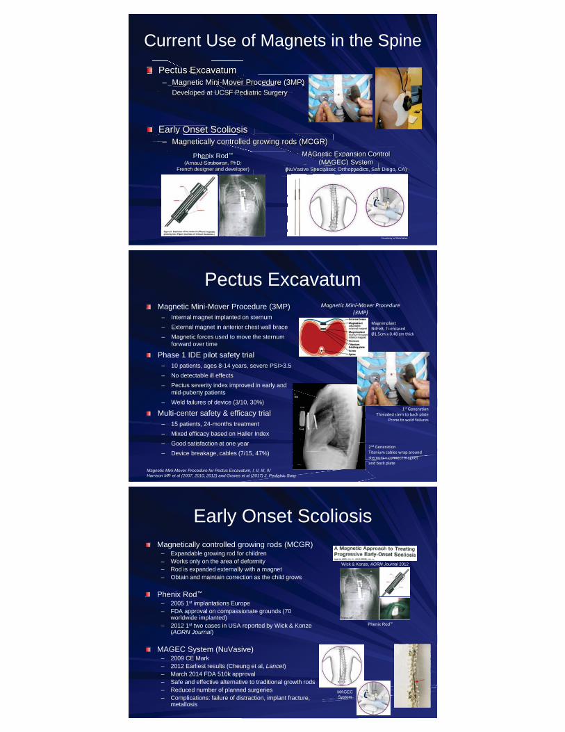
Magnetic Disc Replacement gnetic Disc Replacemc Replacemtic ac mRepulsion Forces
0
10
20
30
40
50
60
70
80
90
0 5 10 15
Forc
e (N
)
Separation Distance (mm)
Repulsion Force for 3mm Magnet Thickness
10
15
20
25
Magnet Diameter(mm)
0
10
20
30
40
50
60
70
80
90
0 5 10 15
Forc
e (N
)
Separation Distance (mm)
Repulsion Force for 5mm Magnet Thickness
10
15
20
25
Magnet Diameter(mm)
Effect of magnet thickness on repulsion force of magnetsForce is dependent on magnet size (diameter and thickness) and separation distance
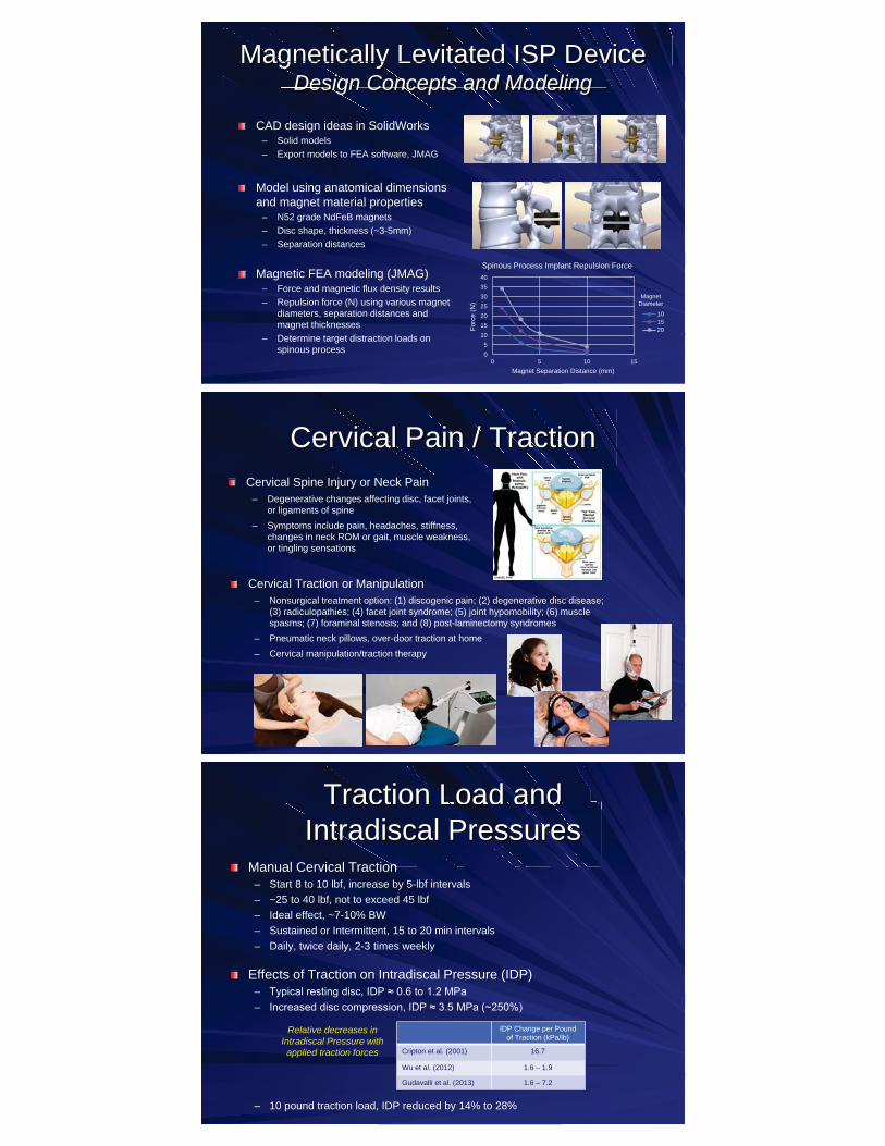
Magnetic Disc Replacement acemcemgnetic Disc Replac Replatic ac mRepulsion Forces
0
20
40
60
80
100
120
0 5 10 15
Rep
ulsi
on F
orce
(N)
Separation Distance (mm)
Repulsion Force for 25mm Diameter Magnets
3mm
5mm
Magnet Thickness
Repulsion forces approach 65 to 120 N as separation distance goes to zero (for Magnet Diameter 25mm)
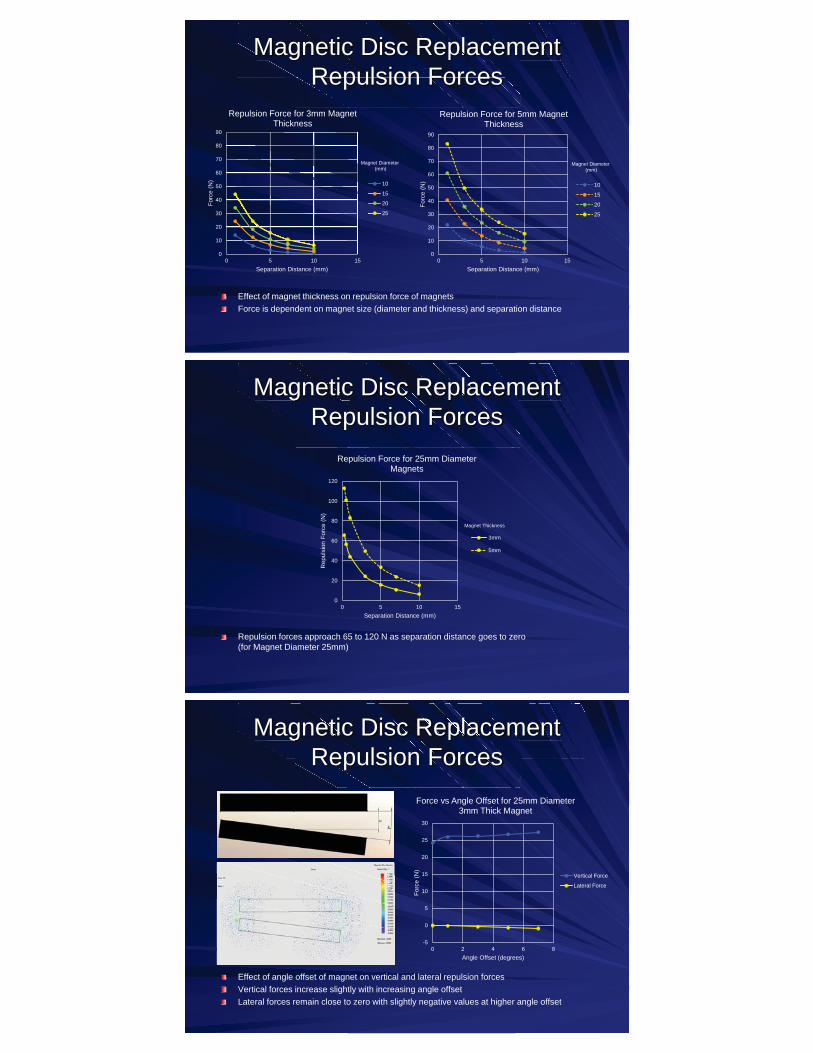
Magnetic Disc Replacement gnetic Disc Replacemc Replacemtic ac mRepulsion Forces
Effect of angle offset of magnet on vertical and lateral repulsion forcesVertical forces increase slightly with increasing angle offsetLateral forces remain close to zero with slightly negative values at higher angle offset
-5
0
5
10
15
20
25
30
0 2 4 6 8
Forc
e (N
)
Angle Offset (degrees)
Force vs Angle Offset for 25mm Diameter 3mm Thick Magnet
Vertical Force
Lateral Force

Contacting articulation design of an artificial disc replacement with magnets
Magnets and Total Disc
t ti ti l ti d i f tifi i l di l tti l ti d i i t ith
Magnets and Total DisM ndd Tota Dinet al sc Replacement in the Spine
Magnetic Repulsion
Force
– Magnets housed in metal fixation plates attached to superior and inferior vertebral endplates
– Magnets repel at the surface articulation and impart a repulsive force on the vertebra
– Repulsive forces reduce contact stresses on the articulating surface of the device
– Reduced wear due to reduction in contact stress
Reduce contact stress
and wear
Review: Magnets in Medicine and Spine
Magnet properties, strengthsg p p , gp ,Advantages/disadvantages of magnets and magnetic field Advant gesAdvantageexposureppClinical uses of magnets s s –– Current and Future–
g– Diagnostic imaging–
g g ggg g– Potential therapeutic benefit–
pp– Dentistry, craniofacial applications, joint replacements, bone Dentistry, craniofacial applicantistry, craniofacial ap licaticatioD
healing, prosthetic attachmentg, p
Numerous spine applications for use of magnetic Numerous sptechnology
THANK YOU