Embed Size (px)
Citation preview

1
William M. Chan
Applications BranchNASA Advanced Supercomputing Division NASA Ames Research Center
7th Symposium on Overset Composite Grid and Solution Technology, Huntington Beach, CA, October 5-7, 2004
ADVANCES IN CHIMERA GRID TOOLS FOR MULTI-BODY DYNAMICS SIMULATIONS AND SCRIPT CREATION
2
OVERVIEW
> Framework for multi-body dynamics -
Geometry Manipulation Protocol (GMP)
> Dynamics simulation using Chimera Grid Tools (CGT)
and OVERFLOW-2
> Further recent developments in Chimera Grid Tools
- OVERGRID
- Grid modules
- Script library
> Summary and future work
3
MULTIPLE COMPONENT DYNAMICS
Motivation - Problem setup is difficult and not standardized
Objective - Develop solver-independent standard protocol Make it easy to use
Approach - Develop protocols and tools for describing - hierarchical relationship between static/moving components, grids, geometry, etc. - prescribed motion - 6-dof motion with external loads and constraints
Murman, S. M., Chan, W. M., Aftosmis, M. J., Meakin, R. L., `An Interface forSpecifying Rigid-Body Motions for CFD Applications’, AIAA Paper 2003-1237,41st AIAA Aerospace Sciences Meeting, Jan., 2003
4
GEOMETRY MANIPULATION PROTOCOL
Configuration Each component may - have one immediate parent or no parent - move relative to the parent - be linked to geometry or grids (structured/unstructured) - have an initial transform (rotate/translate/mirror)
Scenario Motion of each component may be Prescribed - sequence of rotate and translate commands that are analytic functions of time Aero6dof - specified by - mass properties (mass, principal moments of inertia, and principal axes orientation) - initial location of center of mass - external loads and constraints (gravity,app. load, etc.)
5
EXAMPLES OF PRESCRIBED AND 6-DOF MOTION
6
MULTI-BODY CFD SIMULATIONS (previous procedure)
> Write special code for dynamics of each component
> Determine how to interface with flow solver by - reading complicated documentation (if any) - talking to flow solver authors (if available)
> Recompile flow solver
> Verify and debug by running flow solver
> Plot grids at different times to check dynamics
7MULTI-BODY CFD SIMULATIONS (current procedure)
Pre-processing using OVERGRID> Define components (hierarchy/grid links)> Specify and verify dynamics before running flow solver - animate prescribed motion - animate 6-dof motion by solving Newton’s and Euler’s equations of motion (zero aero loads assumed)> Write XML files for flow solver to read
Solution computation using OVERFLOW-2> Read XML files from OVERGRID for dynamics input> No code writing, recompilation or knowledge of flow solver interface needed
Post-processing using OVERGRID and OVERPLOT> Animate 6-dof motion of components> Animate scalar quantities with simple solution viewer> Plot component force/moment breakdown, residuals,etc.
8
CURRENT VALIDATED CAPABILITIES IN OVERFLOW-2
> Each component undergoes either prescribed or 6-dof motion for all time
> Some components may have prescribed motion followed by 6-dof motion
> Applied forces and moments for 6-dof motion are allowed to be functions of time
> Simple constrained 6-dof motion is coded but not validated yet
9
VALIDATION TEST CASES FOR GMP DYNAMICS
Comparison with analytic solutions (aero-loads turned off)
> Sphere dropped under gravity - initially at rest, with time varying resistive force - with initial upward velocity > Tumbling cylinder pinned at center of mass (no gravity) - with initial angular velocity
Comparison with experiments
> Oscillating airfoil - prescribed motion, dual time step -0.2 <= alpha <= 8.2 (case 1) 6.8 <= alpha <= 15.2 (case 2) 10.8 <= alpha <= 19.2 (case 3)
10
OSCILLATING AIRFOIL TEST CASE 1
-0.2 <= alpha <= 8.2, DTPHYS=0.157, 200 steps/cycle
Lift
Drag
Pitchingmoment
Multiple-grid - 40 sub-iterations - 80 sub-iterations
Single-grid - 20 sub-iterations
ReferenceKo, S. and McCroskey, W. J.,Computations of UnsteadySeparating Flows over anOscillating Airfoil, AIAA Paper 95-0312, 1995.
11OVERPLOT POST-PROCESSING INTERFACERESIDUALS PANEL
12
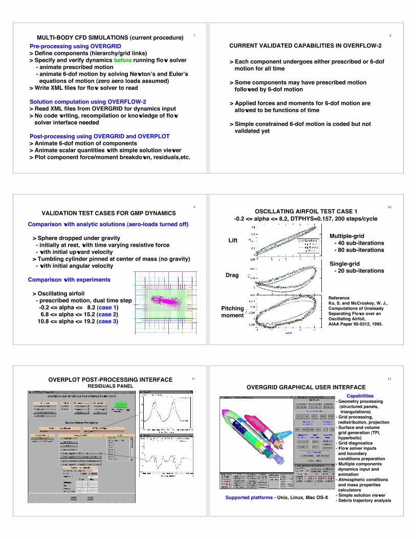
OVERGRID GRAPHICAL USER INTERFACE
Capabilities- Geometry processing (structured panels, triangulations)- Grid processing, redistribution, projection- Surface and volume grid generation (TFI, hyperbolic)- Grid diagnostics- Flow solver inputs and boundary conditions preparation- Multiple components dynamics input and animation- Atmospheric conditions and mass properties calculators- Simple solution viewer- Debris trajectory analysis
Supported platforms - Unix, Linux, Mac OS-X

13
Calculators for Standard Atmosphere Freestream Properties and Mass Properties of Arbitrarily-Shaped Objects
Principal axesof inertia
Given:- altitude- speed- ref. lengthReturn:- Mach no.- Reynolds no.- temperature- density- viscosity- sound speedGiven:- surface- triangulation- densityReturn:- mass, volume- surface area- c. of mass- principalmoments/axesof inertia
14
SOLUTION VIEWER FOR SINGLE/MULTIPLE TIME FRAMES
Grid frame Q frame Solutions Single Single 3-D steady state Single Multiple 3-D time accurate or non-time accurate Multiple Multiple 3-D time accurate moving bodies, 2-D dynamic adaptive grids
Need a fast way to look atdynamic solutions
Auto-loading of all L=1surfaces
4 clicks to animation withauto file ext. detection - select multiple frames - read grid frames - read q frames - play or record
Usual scalar functions &all q variables (species,turbulence model vars.) - Color contours - Grid wireframes
15
DEBRIS TRAJECTORY ANALYSIS INTERFACE
> Specify
- uniform or random sample distribution
- shape (general / box / cylinder / sphere / tumbling disk /
broadside disk / frustum / micro-sphere/cylinder)
- attribute range(min and max) for density,
length/width/height/diameter, normal offset distance,
velocity magnitude and direction (elevation, azimuthal)
> Specify and view initial debris positions, velocity vectors
> Auto-generate input file for DEBRIS code
> Option to execute DEBRIS code and view trajectories,impact points colored by impact speed
OVERGRID/DPREP DEBRIS DPROX
GUI/script input preparation
Trajectorycomputation
Proximity detection
16OVERGRID DEBRIS TRACING INTERFACE
Initial positions andvelocity directions display
Input parametersspecification panel
17DISPLAY OF TRAJECTORIES, IMPACT POINTS AND SPEEDS IN OVERGRID’S DEBRIS INTERFACE
Impact points colored by impact speed
Debris release points
18
CAT SCAN UTILITY - TSCAN
- Compute cross-sectional area
versus X/Y/Z of a triangulated object at specified angle of attack and yaw
- Estimate wind tunnel blockage
- Proper treatment of non-simply- connected regions

19
PIPE CORE GRID GENERATION TOOL - GENCORE
Automatic generation of singularity-free volume gridsinside varying-diameter pipe
- avoids singular axis topology- core automatically created from pipe shell
20
CGT SCRIPT LIBRARY DEVELOPMENT
> Macro Tcl procedures for grid generation script creation> Factor of 10 or more compact scripts> Factor of 3 or more faster in script development
Library procedures - File manipulation (e.g., combine files, …) - Grid information (e.g., interrogate dimensions, grid coordinates, arc lengths, …) - Grid editing (e.g., extract, concatenate, split, duplicate, swap/reverse indices, translate, rotate, revolve, …) - Grid redistribution - Grid generation (e.g., TFI surface, hyperbolic and Cartesian volume, …) - Math functions - OVERFLOW namelist i/o - Program execution and error checking
21
CGT SCRIPT LIBRARY EXAMPLES
set id [ open grided.i w ]puts $id "in.dat"puts $id " 1 1 ITIN,ITOUT"puts $id " 1 MOP"puts $id " 1 NGSO"puts $id " 5"puts $id " 11 IOP"puts $id " 1 -1 1 JS,JE,JI"puts $id " 1 1 1 KS,KE,KI"puts $id " 1 1 1 LS,LE,LI"puts $id " 0 IYN"puts $id " 1 IYN"puts $id " 1 MOP"puts $id " 1 NGSO"puts $id " 17"puts $id " 11 IOP"puts $id " 1 -1 1 JS,JE,JI"puts $id " 1 -1 1 KS,KE,KI"puts $id " 1 1 1 LS,LE,LI"puts $id " 0 IYN"puts $id " 1 IYN"puts $id " 9 MOP"puts $id "out.dat"puts $id " 2 NWRITE"puts $id " 5, 17"puts $id " 0 IYN"close $idexec $File(GRIDED) < grided.i >& grided.o
Extract K=1 curve of grid 5 andentire grid 17 from file in.dat andwrite result to out.dat
ExtractSubs in.dat out.dat \ [list 5 1 -1 1 1 1 1] [list 17]
Redistribute surface grid from filein.sur for all points in J direction with - max stretching ratio of Sr - end spacings of Ds1 and Ds2 - max spacing no larger than Dsmax - number of points that will allow 3 levels of multi-gridand write result to out.sur
SrapRedist in.sur out.sur 1 J 1 5 3 \ [list 1 -1 $Sr $Ds1 $Ds2 $Dsmax]
22
CGT SCRIPT LIBRARY APPLICATIONSN-STAGE LIQUID ROCKET SUB-SYSTEMS
shroud
igv
impeller
diffuser
hub
ObjectivesDevelop script system toautomatically generate - grids - hole-cutting X-ray maps - domain connectivity inputs - flow solver inputs
Capabilities- component modules for - blade (inducer, inlet guide vanes, impeller, diffuser) - ring (hub to shroud section) - pipe (shroud only) - nose (hub end) - flowliner (bellows, valves, slots) - strut assembly (hub, vanes, brackets)
23CGT SCRIPT LIBRARY APPLICATIONSCOMPUTER ROOM AIR FLOW SIMULATION
Developed script to create - geometry - viscous overset surface and volume grids - boundary conditions, domain connectivity, and flow solver inputsParameterized inputs for - room dimensions - protuberance sizes and coordinates
CoolerPower unit
Cable tray
CPU rack
Mass storage
Perforated floor tiles
Script created inabout 3 man days
12 million points102 grids
Control room
Disk rack
24
Cooler (outflow, specify normal velocity)
Perforated floor tiles(inflow - specify velocity and temperature)
CPU rack hot face(inflow - specify velocity and temperature)
CPU rack cold face(outflow - specify normal velocity)
Viscous walls on all solid surfaces except
CGT SCRIPT LIBRARY APPLICATIONSSCRIPT-GENERATED BOUNDARY CONDITIONS FOR COMPUTER
ROOM SIMULATION

25
SUMMARY
Tool suite (OVERGRID, OVERFLOW-2, OVERPLOT)
- developed for rapid, easy-to-use multi-body dynamics CFD simulations - includes grid generation, input preparation, flow computation, dynamics animation, simple flow visualization, history plots of residuals, forces, moments, dynamics data, etc.
Expanded script library in CGT
- simplifies grid generation script creation - more compact scripts - less development time
26
FUTURE WORK
Over 100 items in CGT development to-do list
Short term - driven by Return-To-Flight and unsteady liquid rocket sub-systems simulations
Medium term - CAPRI interface for grid generation on native CAD models
Long term - hybrid overset grid technology