Embed Size (px)
Citation preview

NASA Contractor Report 189606
/J/ I/i// •
/
t
Advanced Transport Operating System (ATOPS)Control Display Unit Software Description
Christopher J. SlominskiMark A. ParksKelly R. DebureWilliam J. Heaphy
Computer Sciences CorporationHampton, Virginia
Prepared ForLangley Research Centerunder Contract NAS1-19038January 1992
National Aeronautics andSpace Administration
Langley Research Center
Hampton, Vi;ginia 23665-5225
([;ASA-CR-I_9606) ADVANCED TRANSPORT
LJPERATING SYSTEM (ATOPS) CQNTRQL O[SPLAY
U'_IT S3FfWA_E DFSCR[PTION (Computer
Sciences Corp.) 347 p CSCt 098
G3/06
N9Z-24689
Unclas
0086862
https://ntrs.nasa.gov/search.jsp?R=19920015446 2018-07-25T11:00:27+00:00Z
-2-
6.2.2
6.2.3
6.3.2
6.3.3
ROUTE TRANSLATION AND PATH DEFINITION ........ 83
CREATE BUF ................................. 84
DEMODE ..................................... 85
DSC WPT .................................... 87
FIND CCD ................................... 88
LOCAL_ERAD ................................. 89
PATH ....................................... 90
PATHDF ..................................... 92
RTA TIMES .................................. 93
RTE ........................................ 94
TRIM_WPTS .................................. 96
WPT ........................................ 97
XLAT RTE ................................... 99
EXECUTE/REJECT THE MODIFIED FLIGHT PLAN ...... 101
EXECUTE .................................... 102
HOLD SET ................................... 104
REJECT ..................................... 105
THE FLIGHT PLANNING PAGES ...................... 107
THE DEPARTURE/ARRIVAL PAGE ................... 109
DA INPUT ................................... 115
DEPARR ..................................... 116
INDX INPUT --. .............................. 117
ITEM_ADDR .................................. 118
ITEM_COUNT ................................. 119
MODIFY ..................................... 120
MOD ROUTE .................................. 122
PAGE_COUNT ................................. 123
REFRESH DA ................................. 124
SET_SIDLINE ................................ 125
THE DIRECT/INTERCEPT PAGE .................... 127
DIRECT ..................................... 131
INTC MGR ................................... 132
INTERCEPT .................................. 133
THE HOLD PAGE ................................ 135
GET_ETA .................................... 141
HOLD_INIT .................................. 142
HOLD__ INPUT ................................. 143
HLD_MGR .................................... 145
HLDWPT ..................................... 146
INDX ........................................ 147
LENGTHS .................................... 148
POINTS ..................................... 149
PROJPOINT .................................. 150
REFRESH_HOLD ............................... 151

-3-
6.3.4
6.3.5
6.3.6
THE LEGS PAGE ................................ 153ADD WPT .................................... 157ALTX ....................................... 158BOUNDS..................................... 159DSP WPTS ................................... 160HLD END .................................... ]62HLD IN ..................................... 163HLD-POS .................................... 164INBOUND .................................... 165INTC END ................................... 166KILL WPT ................................... 167LEGS ....................................... 168LEG END .................................... 170LEG MGR .................................... 171NEWCTR..................................... 172NEWENTRY .................................. 173NEXT WPT ................................... 174NMBRS...................................... 175PAD NAME ................................... 176PROGNUM ................................... 177SET PG ..................................... 178SPLIT ...................................... 179STEPS ...................................... 180WPNAME..................................... 181WPT ADDR ................................... 182WPT DATA ................................... 183
THE LEGS TIME PAGE ........................... 185DSP TIME ................................... 189ECHOTIME .................................. 190LEG TIME ................................... 191TIME IN .................................... 192
THE ROUTEPAGE ............................... 193ACT EXIT ................................... 199AIRPORT .................................... 200BREAK ...................................... 201CLEAN PPT .................................. 202COMPANY.................................... 203DATA IN .................................... 204DEL IN ..................................... 206DEL RTE .................................... 207DSC CHECK .................................. 208ECHO ....................................... 209ENTRY WPT .................................. 210EXIT ....................................... 211EXIT WPT ................................... 212FIND PPT ................................... 213FIND RTE ................................... 214GROUP...................................... 215INIT PLAN .................................. 217
-4-
6.3.7
7.07.1
7.2
7.3
INTC WPTS .................................. 218INT LEG .................................... 220KILT ....................................... 222MAKE WPT ................................... 223MERGE ...................................... 224NEWPOS .................................... 225OPEN ....................................... 226ORGRWY .................................... 227PROGSCR ................................... 228REMOVE..................................... 229ROUTE ...................................... 230RTE ID ..................................... 231RTE INTC ................................... 232RTE WPT .................................... 234SEQUENCE................................... 235SLASH ...................................... 236TITLE ...................................... 237TYPE WPT ................................... 238UPDATE ..................................... 239WAYPOINT ................................... 241WPT ID ..................................... 243XYPOS ...................................... 245
THE ROUTE INDEX PAGE ......................... 247PGA ........................................ 251RTENDX ..................................... 252
THE INITIALIZATION AND REFERENCEPAGES ......... 253THE INIT/REF INDEX PAGE ........................ 255
INITREF ...................................... 259THE SYSTEMIDENTIFICATION PAGE ................. 261
IDENT ........................................ 265THE REFERENCENAVIGATION DATA PAGE ............. 267
AIR INPUT .................................... 271AIR PAGE ..................................... 272CLEAR ENTRY .................................. 273LIST INPUT ................................... 274LIST PAGE .................................... 275MAGV--......................................... 276NAME LEN ..................................... 277NAME PTR ..................................... 278NAV INPUT .................................... 279NAVPG ........................................ 280PROCESSAIRWAY ............................... 281PROCESSARP .................................. 282PROCESSGRP .................................. 283PROCESSNAV .................................. 284PROCESSRWY .................................. 285REFRESH...................................... 286SET CENTER ................................... 287SET LIST ..................................... 288SUBNAVINPUT ................................. 289
-5-
7.4
7.7
7.8
7.9
7.10
7.11
8.0
THE INITIAL POSITION PAGE ...................... 291INITPOS ...................................... 295INITUP ....................................... 296STRIPR ....................................... 297
THE EPR LIMIT PAGE ............................. 299EPRLIM ....................................... 303
THE PROGRESSPAGE .............................. 305ACTION ....................................... 311PROGRESS..................................... 312
THE PERFORMANCEINITIALIZATION PAGE ............ 315PFINIT ....................................... 319PFINP ........................................ 320FUEL LIM ..................................... 324
THE STATUSPAGE ................................ 325STATPG ....................................... 329STNDRDINP ................................... 330
THE APPROACHREFERENCEPAGE .................... 331APPREF ....................................... 335VREFLU ....................................... 336
THE TAKEOFFREF PAGE .......................... 337TKOFF ........................................ 343TKOFFINP ..................................... 346PROCDEL ..................................... 350MANUAL ....................................... 351INTRP ........................................ 352EPRTO ........................................ 353TOSTBP ....................................... 354
THE GPSS PAGE ................................. 355GPSPG ........................................ 359SHOWGPS ..................................... 360
THE PHASE OF FLIGHT PAGES ...................... 361CLIMB ........................................ 369CRUISE ....................................... 370DESCENT...................................... 371FLT TYPE ..................................... 372FLT TYPE INP ................................. 374FIND TOD ..................................... 377CHNGPG ...................................... 378SPEEDB ........ ,............................... 379PROGLN ...................................... 381RTA LN8 ...................................... 382RTA--LN9 ...................................... 383RTA LNI0 ..................................... 384

9.0 THE FIX PAGE ................................... 385FIX INFO ..................................... 391OUT RAD ...................................... 393
FIX INP ...................................... 394
FUNC INP FIX ................................. 395
DATA INP FIX ................................. 397
DEL FIX ...................................... 399
CH FIX PG .................................... 400
FIX INIT ..................................... 401
COMP ABRAD ................................... 402
FIND LEG AB .................................. 403
UNITVEC ...................................... 404
FMIN ......................................... 405
FIX ERAD ..................................... 406
AB IP LL ..................................... 407
COMP RAD ..................................... 408
FIND LEG RAD ................................. 409
F ANG(X, Y, ANG) ............................. 410COMP ANG ..................................... 411
POS INFO ..................................... 412
COMP IP DTG .................................. 413
FIX DISP ..................................... 414
Appendix A PATH DEFINITION COMPUTATIONS ............. 415
-7-
LIST OF FIGURES
1.02.02.13.04 06 16 26 36 46 56 66.76.86.96.107.07.17.27.37.47.57.67.77.87.97.107.117.128.08.18.29.09.1
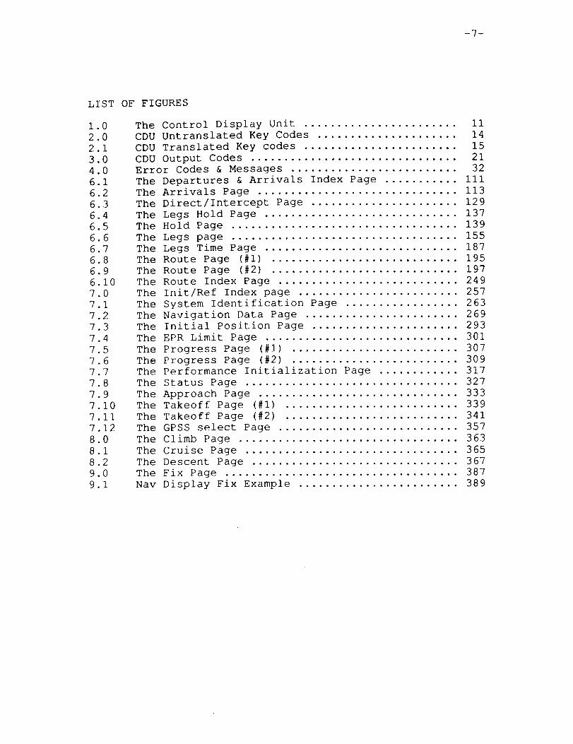
The Control Display Unit ....................... iiCDU Untranslated Key Codes ..................... 14CDU Translated Key codes ....................... 15CDU Output Codes ............................... 21Error Codes & Messages ......................... 32The Departures & Arrivals Index Page ........... iiiThe Arrivals Page ..., .......................... 113The Direct/Intercept Page ...................... 129The Legs Hold Page ............................. 137The Hold Page .................................. 139The Legs page .................................. 155The Legs Time Page ............................. 187The Route Page (#I) ............................ 195The Route Page (#2) ............................ 197The Route Index Page ........................... 249The Init/Ref Index page ........................ 257The System Identification Page ................. 263The Navigation Data Page ....................... 269The Initial Position Page ...................... 293The EPR Limit Page ............................. 301The Progress Page (#I) ......................... 307The Progress Page (#2) ......................... 309The Performance Initialization Page ............ 317The Status Page ................................ 327The Approach Page .............................. 333The Takeoff Page (#I) .......................... 339The Takeoff Page (#2) .......................... 341The GPSS select Page ........................... 357The Climb Page ................................. 363The Cruise Page ................................ 365
The Descent Page ............................... 367
The Fix Page ................................... 387
Nav Display Fix Example ........................ 389


-9-
Section 1.0 INTRODUCTION TO CDU SOFTWARE
The following sections of this document describe the
CDU software which runs on the Flight Management/Flight
Controls VAX computer on-board the TSRV. All the software,with the exception of two small modules, is built into the
flight management background process SLOW. The remaining
modules, CDUFST and KEYBRD, serve as the CDU's foreground
interface and are built into the processes FMFAST and HDL
respectively. CDU applications running in the background
means that no definitive timing exists for the repetitive
scheduling of CDU operations and the software may be inter-
rupted at any point by time critical foreground software.
Data structures shared by both background and foreground
must be synchronized through software flags.
Two important functions of the CDU software include
the management of the CDU interactive display and the
flight management functions performed in assisting the
flight crew in choosing and following a flight plan.
Operations performed with CDU software affects the air-
crafts guidance, navigation, and display software. The
actual CDU hardware is a Lear-Siegler unit having 14
display lines of 24 character width. There are also
5 programmable display lights on the face of the key-
board. Besides alphanumeric data keys, there are six line
select keys (LSK) on each side of the display area. See
figure 1.0.
I_ _______.INT_:,,T_0_._LtY _ pRIBCEDtNG PAG_c BtANK NOT Ft,LMED


-11-
0
®®®®®®®®®@@@
(figure 1.0)
PA_f.__) tN]'ENT.IONALLYBLA,N_ PI:_="CE:D'INGPAC,£ BLANK NOT FILMED


-13-
Section 2.0 CDU INPUT DATA
Input to the CDU comes from two sources. Most CDU
data is received from flight crew entries on the Lear-
Siegler keyboard, however data input for the CDU software
may also come from the data-link. Information on data
link I/O is contained in the CDU data-link description
(section 5).
Keyboard entries received by CDU software are of two
types; function and buffered data. Function entries consist
of one key code (one byte of data) while data entries have
one to 16 bytes of ASCII data followed by a termination key
code. The termination code is from either a line select key
or the sampled scratch pad code, 'FF' hex. The key codes
sent by the Lear-Siegler unit are non-standard character
codes which must be translated into usable data for CDU
software. The module KEYBRD performs the translation upon
receiving the data in the I/O handler process (HDL). The
alphanumeric codes are mapped into their ASCII counterparts
for ease of use in the software. Figures 2.0 and 2.1 show
the codes both before and after the translation process.
Once the code translation is complete the data is stored
in the global input buffer, ENTRY. The first byte of ENTRY is
set to the key code count. All function entries will have
the count byte set to one, data entries will be from two to
seventeen. Note that when the CDU applications have finished
processing the keyboard input, the count byte is cleared.
Data entry is initiated by any alphanumeric keystroke.
At that time the CDU will automatically clear all of line
#14 (CDU data entry line), then echo the character at the
start of line #14 (the CDU is now in data entry mode).
During data entry mode any line #14 update sent to the CDU
from the host computer will be ignored. When a function key
is selected during data entry mode the function code will be
immediately sent to the host, with no effect on the current
scratch pad entry. The CLR function will not be passed to
the host computer unless the scratch pad is inactive. When
data entry is in progress, the CLR will be used by the CDU
to either delete one or all characters from the scratch pad
depending on duration of selection. When all characters are
deleted from the scratch pad the CDU will exit data entry
mode and allow line #14 updates. When data entry is
completed by a LSK selection the scratch pad line is cleared
and data entry mode is canceled.
Data buffering by the CDU may be disabled by the host
software. When this situation arises the CDU scratch pad
will be cleared and disabled. Neither direct key entry
nor host software scratch pad programming will place the CDU
in data entry mode. Note that line #14 of the display
screen will always be available as a display line when data
buffering is disabled. All key entries, including line select
keys, will be sent immediately as single key function
entries (count = I). This process will continue until the
host computer commands the re-enabling of data buffering.
PRECEDING PAGE BLANK NO[ FILMED

-14-
Figure 2.0
KEY
CDU UNTRANSLATED KEY CODES
CODE KEY CODE KEY CODE
00H K 20H
01H P 21H
02H U 22H
03H Z 23H
LSK L2 04H F 24H
LSK L1 05H A 25H
LSK R1 06H LEGS 26H
LSK R2 07H RTE 27H
1 08H L 28H
4 09H Q 29H
7 0AH V 2AH
0BH (BLANK) 2BH
LSK L4 0CH G 2CH
LSK L3 0DH B 2DH
LSK R3 0EH DEP ARR 2EH
LSK R4 0FH CLB 2FH
2 10H M 30H
5 IIH R 31H
8 12H W 32H
0 13H DEL 33H
LSK L6 14H H 34H
LSK L5 15H C 35H
LSK R5 16H HOLD 36H
LSK R6 17H CRZ 37H
3 18H N 38H
6 19H S 39H
9 IAH X 3AH
+/- IBH / 3BH
NEXT PAGE ICH I 3CH
FIX IDH D 3DH
DIR INTC IEH PROG 3EH
INIT REF IFH DES 3FH
NOTE (i) : CLR KEY CODE FOR KEY ENGAGED
< 1/2 SEC 48H, > 1/2 SEC C8H
0 40H
T 41H
Y 42H
43H
J 44H
E 45H
EXEC 46H
47H
CLR (I) 48H
PREV PAGE 49H
NI LIMIT 4AH
4BH
4CH
4DH
4EH
4FH
CLR (i) C8H

-15-
Figure 2.1 CDU TRANSLATEDKEY CODES
HEX VALUE KEY
0001-0C0D-0F
10ii1213141516171819IAIBICIDIEIF
2O21222324-2C2D2E2F
30-393A-3F
4041-4F
50-5A5B-5F
60-FEFF
line select 1-12
INIT REFDIR INTCN1 LIMITRTELEGSFIXCLBDEP ARRCRZHOLDDESPROGPREV PAGENEXT PAGEEXEC
(blank)short CLRlong CLRDEL
0-9
scratch pad terminater


-17-
Section 3.0 CDU OUTPUTDATA
The CDU display screen consists of 14 lines of 24characters each. The top and bottom lines are referred toas the title and scratch pad lines respectively. Thetitle line identifies the active CDU display page and thescratch pad line is alternately used as a data entry andwarning display line. The lines in between are identifiedas line #i through #12. Typically odd numbered lines areused as label lines where text is written in small font.The even numbered lines except #12 are normally used asdata entry and display lines. Line #12 often has specialcontrol tags such as "ERASE>". The six line select keyson each side of the display correspond to label/data linepairs. For example the top LSK is positioned betweenlines #I and #2.
The data transmission to the Lear-Siegler ControlDisplay Units is a variable length byte stream consisting ofcharacter codes (OOH- 7FH) and special functions (8OH -FFH). The visible representation for each character code isshown in figure 4, page 26 of the Design Requirement Speci-fication for the CDU. Only a subset of the existing symbolsis used by CDU software. Figure 3.0 outlines the symbolsand their hex codes used for the NASA CDU software. Theminimum amount of data that can be modified in one update isone 24 character line on the display. However any number oflines may be updated at once. The CDU software sets the
flag IOWAIT when a block of data is complete. CDU software
remains idle until the I/O handler process transmits the
data to the CDU I/O processor (CVIU) and clears the flag.
The utility procedure FMTOUT is used to build the CDU
output buffer. This module inserts the special control
codes into the data stream for the applications software
when called with the various parameters available. The next
section describes the use of FMTOUT.
The remainder of this section describes the special
control codes placed in the output buffer. The sign bit of
all function codes is set, therefore CVIU software parsing
the transmitted data can quickly identify leading, trailing,
and embedded functions. The high order nibble of a function
byte is the function identifier and the low order nibble is
the function qualifier. Therefore there are eight distinct
CDU functions (8xH - FxH), each having 16 qualifiers.
The following pages describe each of the defined function
identifiers and the effect of the various qualifiers.
PAn--IN _E_J/JLJ_LLY I_L,_/t_
PRECEDING PAGE. BRAN1( NOT FILMED

-18-
FUNCTION "8X" (I000 .... binary); CLEAR LINE
This function is used to blank a line on the CDU display.The qualifier bits designate which line is to be cleared.
Since there are 14 display lines on the CDU screen valid
values for this function are 81H through 8EH.
The count function "Ax" is placed immediately following
the clear line function to blank a number of contiguous
lines of the display.
The entire screen can be cleared by the two bytes "81H,AEH".
FUNCTION "9x" (i001 .... binary) ; UPDATE LINE
This function is used to replace all 24 characters on a
CDU display line. The qualifier bits designate the line
which will be updated. The count function "Ax" can follow
the update function to replace a number of consecutive lines.
Valid values for this function are 91H through 9EH.
Directly following the updated function, or the count
function if supplied, are the ASCII character bytes used to
fill the designated line(s). For example, the following 25
bytes place an ASCII zero, "0", in each character position ofline number three.
93H, 30H, 30H, ...... 30H
FUNCTION "Ax" (1010 .... binary); LINE COUNT
This function is used to make the clear and update
functions (Sx and 9x) work over a range of display lines.
The count function is valid only when immediately succeed-
ing the other two functions in the data stream.
The valid set of values for this function are AIH
through AEH.

-19-
FUNCTION "Bx" (i011 .... binary); sample scratch pad
This function requests immediate sampling of the CDUscratgh pad. The qualifier bits are undefined for thisfunction. When the "Bx" function is received any currentdata entry is terminated and sent to the host computer as if
a LSK was pressed by the pilot. The scratch pad is cleared
and data entry mode is disabled. The termination byte,
normally the selected LSK code, will be FFH.
When no data exists on the scratch pad just the
terminator code is sent just like an LSK press with no data
(ie count byte = I).
FUNCTION "Cx" (Ii00 .... binary); SET MODE
The mode function handles several miscellaneous CDU
operations. In particular there are eight mode commands
(COH - C5H, CEH, CFH) which are described below.
- CO -
This code is the end of transmission byte which is always
the last byte of the data block.
- C1 -
Mode qualifier "i" causes the CDU to be initialized.
After this byte is processed the display screen is clear,
all lights are off, video is standard, data entry is
disabled and data buffering is enabled.
- C2 -
Sets standard video. All text written to the CDU after
receiving this function will have the standard video
characteristic. Note that this code may be imbedded within
an ASCII text string.
- C3 -
Sets reverse video. All text written to the CDU after
receiving this function will have the reverse video
characteristic. Note that this code may be imbedded within
an ASCII text string.
- C4 -
Disables CDU data buffering. Keystrokes will be sent
immediately to the host computer as function entries.

-20-
- C5 -Enables CDU data buffering. Data may be entered on the
scratch pad by manual entry or software programming.
- CE -Selects pilot's CDU. This function (or CF) must always
be the first byte of the data sent to the CDU. This byteis always followed by the CDU "lights" byte described below.
- CF -Selects co-pilot's CDU. This function (or CE) must
always be the first byte of the data sent to the CDU. This
byte is always followed by the CDU "lights" byte described
below.
CDU lights byte:
This byte is always the second byte of a transmission from
the host computer. The low-order 5 bits represent the
desired status of the CDU lights (bit set = light on).
The bits are assigned as follows.
0 FAIL
1 DSPY
2 MSG
3 OFST
4 EXEC
I) Note that when the MSG light is on, no scratch pad entry
may be started by either keyboard entry or scratch pad
programming with function "Dx". Any entry on the scratch
pad when MSG is set on can be finished and transmitted with
a LSK.
FUNCTION "Dx" (ii01 .... binary); SCRATCH PAD UPDATE
Function D is used to place a text string into the scratch
pad as if it had been manually entered via the keyboard. The
qualifier bits indicate the number of characters in the update
string (offset by one; 0 means I, F means 16). Note the
string of characters immediately follows the function byte.Valid values for this function are D0H - DFH. The three
bytes given below would clear the scratch pad of any existing
entry and place the text "i0" into the scratch pad area.
Note that the CDU will be in data entry mode after receiving
a "D" function.
DIH, 31H, 30H

-21-
Figure 3.0 CDU OUTPUTCODES
00-0F10-19IA-IF20-222324252627-3F4041-5B5C5D5E5F6061-7A7B7C7D-FF
small font digits (0-9)
standard ASCIIdegrees Fdegreesstandard ASCIIdegrees C
standard ASCII
box
standard ASCII
standard ASCII
standard ASCII
small font alphabet
standard ASCII

-23-
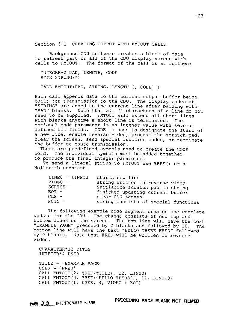
Section 3.1 CREATING OUTPUTWITH FMTOUTCALLS
Background CDU software creates a block of datato refresh part or all of the CDU display screen withcalls to FMTOUT. The format of the call is as follows:
INTEGER*2 PAD, LENGTH, CODEBYTE STRING(*)
CALL FMTOUT(PAD, STRING, LENGTH [, CODE] )
Each call appends data to the current output buffer beingbuilt for transmission to the CDU. The display codes at"STRING" are added to the current line after padding with"PAD" blanks. Note that all 24 characters of a line do not
need to be supplied. FMTOUT will extend all short lines
with blanks anytime a short line is terminated. The
optional code parameter is an integer value with several
defined bit fields. CODE is used to designate the start of
a new line, enable reverse video, program the scratch pad,
clear the screen, send special function codes, or terminatethe buffer to cause transmission.
There are predefined symbols used to create the CODE
word. The individual symbols must be added together
to produce the final integer parameter.
To send a literal string to FMTOUT use %REF() or a
Hollerith constant.
LINE0 - LINE13
VIDEO -
SCRTCH -
EOT -
CLS -
FCTN -
starts new line
string written in reverse video
initialize scratch pad to string
finished updating current bufferclear CDU screen
string consists of special functions
The following example code segment creates one complete
update for the CDU. The change consists of new top and
bottom lines on the screen. The top line will have the text
"EXAMPLE PAGE" preceded by 2 blanks and followed by i0. The
bottom line will have the text "HELLO THERE FRED" followed
by 9 blanks. Note that FRED will be written in reversevideo.
CHARACTER*I2 TITLE
INTEGER*4 USER
TITLE = 'EXAMPLE PAGE'
USER = 'FRED'
CALL FMTOUT(2, %REF(TITLE), 12, LINE0)
CALL FMTOUT(0, %REF('HELLO THERE'), II, LINE13)
CALL FMTOUT(I, USER, 4, VIDEO + EOT)
PI:_ECEDING PAGE BLANK NOT FILMEDpAt__ tNIENTIONALLY BLAf_


-25-
Section 4.0 CDU EXECUTIVE
This section contains the module descriptions for CDU
executive software. The executive software performs
miscellaneous functions that are independent of the
currently displayed CDU page. There are five modules
described in this section. The remaining executive modules
are associated with the data-link portion of the CDU and are
described in section 5. The majority of the CDU exec-
utive sofware, including data-link, is found on the file
CDUEXC.FOR.
Af '"TF.T,0 AttYBLA pR_)tt',tG PAc._E BtA ,_'Vw-NOT F,'_..MED

-26-
MODULENAME:FILE NAME:PROCESS:CALLED BY:CALLING SEQUENCE:
CDUEXCCDUEXC.FORSLOWSLOWCALL CDUEXC
PURPOSE:TO manage those CDU functions which are independent
of the current CDU display page.
DESCRIPTION:This module performs several miscellaneous operations
for the CDU software. Since most sections of the moduleare unrelated, the operations are simply itemized below inthe order found in CDUEXC.
Cause transmission of the CDU initialize code on startup of the software.
Inhibit all CDU software until the I/O handler has
completed last output.
Initialize output buffer with the predifined start byte
and the CDU lights byte.
Call MESSAGE MGR upon detecting data-link inputs•
_. Call EXEC FCTN to handle special CDU function entries
not destined for specific page manager sofware.
Compute the barometric pressure altitude correction
value and issue baro-set alert when traversing the
18,000 foot threshold.
Call active page manager software.
Perform auto-update of waypoints every ten seconds
when required by 'POS' type waypoints. Calls
UPDATE POS.
Manage "North-up" map display center position.
• Place appropriate error messages into CDU output
buffer when problems detected by the various page
managers. Errors will be placed in the buffer each
time a new one is generated until the CLR key has
been pressed to acknowledge the error. At that time
the error message is replaced with the original
scratch pad entry which caused the error• Warning
messages are only sent out one time. Acknowledgement
by CLR entry is not required for these• See figure
4.0 at the end of this section for error codes and
their associated message.

-27-
GLOBAL REFERENCES:
VARIABLESALTCOR BARSET* BARSFT* CDUCNT* CDU INIT* CDU MODECTRF*ERCODE* IOWAIT LT DSPY LT EXEC LT WAIL LT MSG* LT OFSTMODCNTPGINIT* PGRQST*POSTIME* TYMETIME--VLD --
ARRAYSENTRY LOKWPTMESSAGEOLDPAGE*
RECORDARRAYSWPT MOD
FUNCTIONSAND SUBROUTINESEXEC FCTN FMTOUTLINK CMD MESSAGEMGR SELECT UPDATE POS

-28-
MODULENAME:FILE NAME:PROCESS:CALLED BY:CALLING SEQUENCE:
EXEC FCTNCDUEXC.FORSLOWCDUEXCCALL EXEC FCTN(SAVE, ER_FLAG)
PURPOSE:TO process CDU function entries not intended for the
current CDU page display module.
DESCRIPTION:When CDUEXCreceives a function entry it calls
EXEC FCTN to determine if the entry is the type handledby the executive. If not, EXEC_FCTNreturns and the entryis used by the current page display module.
The types of function entries handled by EXEC FCTNare listed below along with a brief description of--theactions taken.
. CDU page selection; The function keycode is used as anindex into a page ID array and placed in the page changerequest variable (PGRQST).
. Clear key (long or short press); If an error message isdisplayed it is replaced with the data entry which causedthe error by a call to RECALL. The message light is alsoturned off. When no error message is shown this functionsimply blanks the bottom CDU line.
Execute key; When the execute light is not on thisfunction is ignored. Otherwise if there is a provisionalflight plan it is made active by a call to EXECUTE. Whenneither condition is true the execute function is assumedto be handled by the current page display software.
If none of the above were true and an error message iscurrently displayed then the entered function (LSK,PREV/LAST page, or DEL) is ignored.
Delete key; The scratch pad line is programmed with the
word "DELETE". Typically this text will be placed at a
particular display line with a LSK to designate thedeletion of a certain CDU item.
GLOBAL REFERENCES:
VARIABLES
ERCODE LT EXEC PGRQST* PMODE
ARRAYS
CDUBUF* ENTRY*
FUNCTIONS AND SUBROUTINES
EXECUTE FMTOUT RECALL

-29-
MODULENAME:FILE NAME:PROCESS:CALLED BY:CALLING SEQUENCE:
RECALLCDUEXC.FORSLOWEXEC FCTN, MESSAGEMGRCALL RECALL(SAVED_ENTRY)
PURPOSE:To recall erroneous data entry.
DESCRIPTION:When CDU entries cause error message displays the
erroneous entry is saved in a buffer "SAVE". The entryis programmed back into the scratch pad by RECALL. Notethat when no text exists for reprogramming (function entryerror for example) the only action is to clear the bottomCDU display line.
GLOBAL REFERENCES:
FUNCTIONS AND SUBROUTINESFMTOUT

-30-
MODULENAME:FILE NAME:PROCESS:CALLED BY:CALLING SEQUENCE:CALLS TO:
SELECTSELECT.MARSLOWCDUEXCCALL SELECT(PAGEID)DSP DUMP, INITREF, IDENT, INITPOS,PFINIT, TKOFF, APPREF, NAVPG, STATPG,ROUTE, CLIMB, CRUISE, DESCENT, LEG__MGR,RTENDX, EPRLIM, PROGRESS,INTC_MGR,DEPARR, FIX INFO, HLD_MGR, LEG_TIME,TEST, RTENDX
PURPOSE:Call the appropriate page manager subroutine.
DESCRIPTION:The variable "PAGE" contains the index of the current
CDU display page. During each iteration of the CDUexecutive, the module SELECT is called to perform thecorresponding call to a page manager listed in a localaddress table. Note that the values for "PAGE" havepredefined symbolic names assigned in the file CODES.CDU.
GLOBAL REFERENCES:none

-31-
MODULENAME:FILE NAME:PROCESS:CALLED BY:CALLING SEQUENCE:
UPDATEPOSCDUEXC?FORSLOWCDUEXCCALL UPDATEPOS
PURPOSE:To update the "POS" type waypoint with current aircraft
parameters.
DESCRIPTION:A provisional flight plan may begin with a "POS" type
waypoint which does not become stationary until the flightplan has been executed. The position, altitude, and speedof the pilot defined waypoint are updated every i0 seconds tothe values of the aircraft. The module DEMODEis called toincorporate the changes into the provisional flight plan.
The variable POSTIME is set to the update time by CDUEXC.During every iteration, POSTIME is compared to the currentaircraft time to check for i0 seconds elapsed. When thisoccurs the call to UPDATEPOS is made. Note that a POSTIMEvalue of zero corresponds to no "POS" waypoint to update.
GLOBAL REFERENCES:
VARIABLESALTCOR GS LAT LON
RECORDARRAYSPPT WPT* WPT MOD
FUNCTIONSAND SUBROUTINESDEMODEFIND PPT
-32-
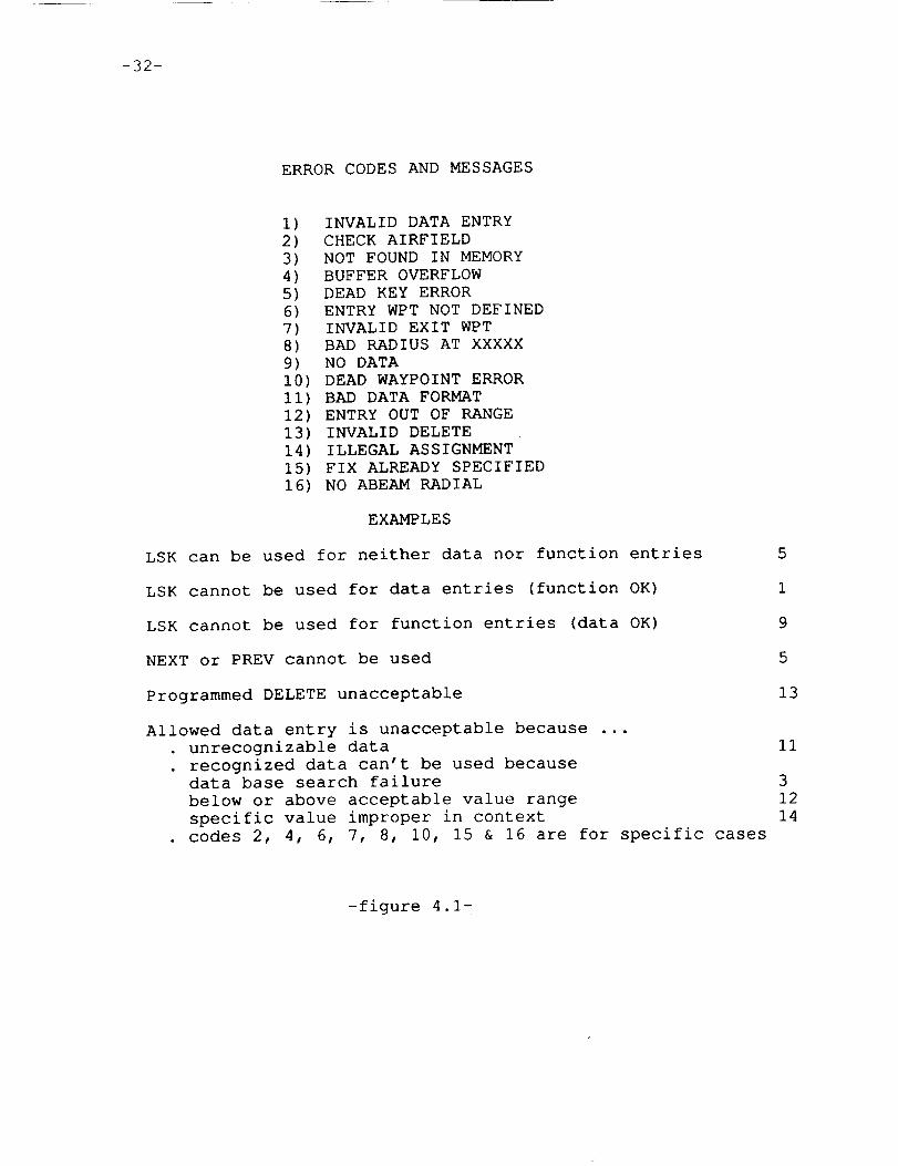
ERRORCODESAND MESSAGES
i) INVALID DATA ENTRY2) CHECKAIRFIELD3) NOT FOUNDIN MEMORY4) BUFFER OVERFLOW5) DEAD KEY ERROR6) ENTRY WPTNOT DEFINED7) INVALID EXIT WPT8) BAD RADIUS AT XXXXX9) NO DATAI0) DEAD WAYPOINTERRORII) BAD DATA FORMAT12) ENTRY OUT OF RANGE13) INVALID DELETE14) ILLEGAL ASSIGNMENT15) FIX ALREADY SPECIFIED16) NO ABEAMRADIAL
EXAMPLES
LSK can be used for neither data nor function entries
LSK cannot be used for data entries (function OK)
LSK cannot be used for function entries (data OK)
NEXT or PREV cannot be used
Programmed DELETE unacceptable
5
1
9
5
13
Allowed data entry is unacceptable because ...
unrecognizable data 11
. recognized data can't be used because
data base search failure 3
below or above acceptable value range 12
specific value improper in context 14
codes 2, 4, 6, 7, 8, I0, 15 & 16 are for specific cases
-figure 4.1-

-33-
Section 5.0 CDU DATA-LINK
One method of input to CDU software is through theTSRV data-link. This method is used to receive clearanceinformation sent by ground controllers. The CDU also isused for data-link outputs when composing messages andsending clearance requests to the ground station.
Two blocks of memory are allocated for data-linkI/O in the global section IPLCOM. The data at theselocations is transmitted between the FM/FC VAX and thedata-link computer every 50 milliseconds. The input areaconsists of 102 bytes of memory. The first 2 bytes arelabeled CDU CMD and are used as a bit control word forcommands from the data-link computer. The remaining 100bytes (LINK IN) may contain a text string uplinked from theground statTon. The memory allocated for output is a 202byte block. The first 2 are bytes used as a control wordto be sent to the data-link computer to describe the text
data stored in the remaining 200 bytes. The first word is
labeled MSG CNT and the text block is CDU MSG. MSG CNT
uses the low byte as a character count of the data in
CDU_MSG. MSG_CNT is not updated until the CDU background
software has completed the entire text buffer. The highbyte of MSG CNT is used to control the use of the text
buffer by the data-link computer. When composing a text
message or sending the current provisional flight plan
to the data-link computer this byte is zero. When the
processing of a new clearance sent by the data-link computeris complete it will be set to FFH, unless an error in the
uplinked clearance was detected. With a clearance error
the byte will contain the character count of an error
message appended to the text buffer. The total length of
the text buffer is then the sum of the low and high bytesof MSG CNT.
The CDU executive calls the module LINK CMD each
iteration of the background process to check--for any data
link commands in CDU CMD. The variable CDU MODE is set
by LINK CMD to signal MESSAGE MGR (called by CDUEXC) to
initiate message handling by the various CDU data-link
modules. The remainder of this section contains module
descriptions for all the CDU data-link procedures.
-34-
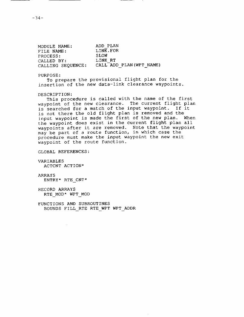
MODULENAME:FILE NAME:PROCESS:CALLED BY:CALLING SEQUENCE:
ADD PLANLINK.FORSLOWLINK RTCALL ADD_PLAN(WPT_NAME)
PURPOSE:TO prepare the provisional flight plan for the
insertion of the new data-link clearance waypoints.
DESCRIPTION:This procedure is called with the name of the first
waypoint of the new clearance. The current flight planis searched for a match of the input waypoint. If itis not there the old flight plan is removed and theinput waypoint is made the first of the new plan. Whenthe waypoint does exist in the current flight plan allwaypoints after it are removed. Note that the waypointmay be part of a route function, in which case theprocedure must make the input waypoint the new exitwaypoint of the route function.
GLOBAL REFERENCES:
VARIABLESACTCNT ACTION*
ARRAYSENTRY* RTE CNT*
RECORDARRAYSRTE MOD* WPTMOD
FUNCTIONS AND SUBROUTINESBOUNDSFILL RTE RTE WPT WPTADDR
-35-
MODULENAME:FILE NAME:PROCESS:CALLED BY:CALLING SEQUENCE:
BEG RTELINK.FORSLOWLINK PDCALL BEG RTE(RTE BUFFER INDEX)
PURPOSE:To prepare the provisional route buffer for proceed
direct assignment.
DESCRIPTION:BEG RTE modifies the provisional route buffer so that
the entry indicated by the input parameter RTE BUFFER INDEXbecomes the second element of the route buffer? To do thisit may eliminate elements, open a new slot at the start, orsimply leave the buffer alone (already #2) depending on thevalue of RTE BUFFER INDEX.
GLOBAL REFERENCES:
FUNCTIONS AND SUBROUTINESKILL OPEN

-36-
MODULENAME:FILE NAME:PROCESS:CALLED BY:CALLING SEQUENCE:
BYTE INCDUEXC.FORSLOWMESSAGEMGRCALL BYTE IN
PURPOSE:To handle CDU keyboard entries during data-link message
composition mode.
DESCRIPTION:When BYTE IN is called one CDU key code resides in the
CDU input buffer, ENTRY. The action taken depends on thetype of key entered. If it was a page change or executekey it is simply passed on to the current page software
called later by the executive. If a line select or delete
key was pressed the entry buffer is cleared and the key is
ignored. All other keys affect the CDU message being com-
posed. A short clear removes the last character from the
text while a long clear clears the entire message. Any
other key received is an alphanumeric which is appended
to the message buffer.
GLOBAL REFERENCES:
VARIABLES
FUNC MSG CNT
ARRAYS
CDU MSG* ENTRY*

-37-
MODULENAME:FILE NAME:PROCESS:CALLED BY:CALLING SEQUENCE:
DELIMITLINK.FORSLOWLINK_EA, LINK PD, LINK RTCALL DELIMIT(TEXT, CNT7 DONE)
PURPOSE:TO parse the data-link clearance message.
DESCRIPTION:This procedure parses the input string TEXT searching
for either a " " or ":" character which are the only
valid terminaters. The string length is returned in CNT
and the boolean flag DONE is returned when at the end of
the clearance message (":" encountered).
GLOBAL REFERENCES: none

-38-
MODULENA/ME:FILE NAME:PROCESS:CALLED BY:CALLING SEQUENCE:
EXPANDRTELINK.FORSLOWDEMODE,LINK_CMD, REJECTCALL EXPANDRTE
PURPOSE:TO create an expanded data-link text buffer for the
data-link display.
DESCRIPTION:When the flight crew desires to request a clearance,
the current provisional flight plan is formatted intothe data-link display buffer for transmission to thedata-link computer. This is performed when the initialrequest is received and each time the provisional flightplan is changed during clearance request mode. Thisprocedure steps through the provisional flight planstoring data into the display buffer with calls toTEXT OUT. The destination airfield and cruise altitudeare also formatted into the buffer.
GLOBAL REFERENCES:
VARIABLESCRZALT MSGCNT
ARRAYSAIRPTS CDU MSG* RTE CNT
RECORDARRAYSRTE MOD
FUNCTIONS AND SUBROUTINESFILL OUT FSTRNGGET LONG TEXT OUT TYPE WPT
-39-
MODULENAME:FILE NAME:PROCESS:CALLED BY:
CALLING SEQUENCE:
FILL OUTLINK_FORSLOWMESSAGE_MGR,LINK_EA, LINK_RT,TEXT_OUT, EXPANDRTECALL FILL OUT(COUNT, BUFFER)
PURPOSE:To fill data into the data-link message buffer.
DESCRIPTION:The data specified by the input parameters is appended
to the data-link display buffer that is built when flightplan clearance information is received. A display bufferpointer is maintained to account for the append position.
GLOBAL REFERENCES:
VARIABLESMSGCNT*
ARRAYSCDU MSG
FUNCTIONS AND SUBROUTINESLIB$MOVC3

-40-
MODULENAME:FILE NAME:PROCESS:CALLED BY:CALLING SEQUENCE:
FILL RTELINK?FORSLOWLINK PD, ADD PLAN
w
CALL FILL RTE(INDEX, ADDRESS)
PURPOSE:
TO make a data-link waypoint entry in the route buffer.
DESCRIPTION:
FILL RTE is called to fill in waypoint information in
the provisional route buffer at the position indicated
by the input parameter INDEX. If the address of the
waypoint is supplied as a non-zero value, the waypoint
is simply entered into the buffer position. Its type
is determined by the function WPT TYPE. When the address
parameter is zero, FILL RTE creates a "POS" pilot defined
waypoint at the current aircraft position and inserts the
created waypoint data into the route buffer. The function
MAKE WPT is used to create the waypoint.
GLOBAL REFERENCES:
VARIABLES
ALTCOR GS LAT LON
RECORD ARRAYS
RTE MOD*
FUNCTIONS AND SUBROUTINES
MAKE WPT TYPE WPT
-41-
MODULENAME:FILE NAME:PROCESS:CALLED BY:CALLING SEQUENCE:
LINK CMDLINK.FORSLOWCDUEXCCALL LINK CMD
PURPOSE:TO serve as the data-link software executive.
DESCRIPTION:LINK CMD is called by the CDU executive (CDUEXC) every
pass through the background software. It monitors thedata-link control word received from the data-link computerto initiate the appropriate actions for the specific datalink commands.
The bits of the data-link control word (CDU CMD) areassigned as follows.
CDU message composition modeClearance information receivedInsert clearance as provisional flight planErase previously received clearanceClear current message composition bufferSend current provisional flight plan to data-link
LINK CMD looks for a change in state of the CDU CMD bits,performing certain operations when a bit changes fromoff to on and others for changes from on to off.
The Insert command from the data-link computer requiresspecial checking in LINK_CMD. If a provisional flight planalready exists when the Insert clearance is commanded theuplinked flight plan is not placed into the guidance buffer.Instead an error message is appended to to expanded flightplan text in CDU MSG. The software then waits for anotherInsert command. When the second Insert is issued and theprovisional guidance buffer is finished LINK CMD restartsthe parsing of the uplink clearance. This occurs since thechanges to the flight plan which were being made may alterhow the clearance affects the current flight plan. When theclearance processing is complete the insertion occursimmediately without response from the data-link computer.
Note that clearance commands may occur during CDU datalink output sequences; data composition or clearancerequests. LINK CMD will save the current output data tomake room for the overriding clearance data. When the newclearance sequence is finished the CDU will be restored tothe previous state of data-link output.
-42-
GLOBAL REFERENCES:
VARIABLESACTION CDU CMD CDU MODE* CRZALT* LNK CNT LNK CRZ MSGCNT*NEWCMD PMODEPOSTIME* SQUATTIME
ARRAYSAIRPTS CDU MSGLNK ARPT LNK RTE MSGBYT* RTE CNT* WX DEF
RECORDARRAYSRTE ACT RTE MOD
FUNCTIONS AND SUBROUTINESDEMODEEXPANDRTE LIB$MOVC3

-43-
MODULENAME:FILE NAME:PROCESS:CALLED BY:CALLING SEQUENCE:
LINK EALINK.FORSLOWMESSAGEMGRCALL LINK_EA(MESSAGE, INDEX, ERR TEXT)
PURPOSE:To handle expected altitude clearances from the data-link.
DESCRIPTION:The input to LINK EA is the parameter MESSAGE. It
contains all the uplinked clearance following the "EA"field found by MESSAGEMGR. The remaining parameters areoutputs. INDEX is the pointer into the data-link inputbuffer LINK IN. It is updated to point to any clearancefollowing the EA data. ERR TEXT is filled with textinformation when an error is detected while parsing theEA data.
The only data used in the EA clearance is an altitudeassignment. The entry is decoded by the function ALTX.The message for the data-link display is created andstored in CDU MSGand the altitude value is saved in theglobal variable LNK_CRZ.
GLOBAL REFERENCES:
VARIABLESACTION* ERCODELNK CRZ*
FUNCTIONS AND SUBROUTINESALTX DELIMIT FILL OUT ISTRNG LIB$MOVC3
-44-
MODULENAME:FILE NAME:PROCESS:CALLED BY:CALLING SEQUENCE:
LINK PDLINK.FORSLOWMESSAGEMGRCALL LINK PD(MESSAGE, INDEX, ERR TEXT)
PURPOSE:TO handle Proceed Direct clearances from the data-link.
DESCRIPTION:The input to LINK PD is the parameter MESSAGE. It
contains all the uplTnked clearance following the "PD"field found by MESSAGEMGR. The remaining parameters areoutputs. INDEX is the--pointer into the data-link inputbuffer LINK IN. It is updated to point to any clearancefollowing the PD data. ERR TEXT is filled with textinformation when an error is detected while parsing thePD data.
When LINK PD is called it finds the waypoint namesupplied in MESSAGEin the navigation data base, AADCOM.Once identified, a search of the provisional route buffer ismade to determine if the waypoint exists on the provisionalflight plan. If it does, all the waypoints preceding theselected waypoint are replaced by an auto-update "POS"waypoint, the remainder of the flight plan is not altered.When the selected waypoint is not part of the provisionalflight plan a provisional flight plan consisting of anauto-update "POS" waypoint and the selected waypoint becomethe only two provisional flight plan waypoints.
Note that the actual route buffer manipulations areperformed through calls to BEG_RTEand FILL_RTE.
GLOBAL REFERENCES:
VARIABLESACTION* ERCODEMSGCNT
ARRAYSCDU MSG* ENTRY* RTE CNT*
RECORDARRAYSRTE MOD
FUNCTIONS AND SUBROUTINESBEG RTE BOUNDSDELIMIT FILL RTE GET LONG KILL LIB$MOVC3
m
TEXT OUT WPT ADDR

-45-
MODULENAME:FILE NAME:PROCESS:CALLED BY:CALLING SEQUENCE:
LINK RTLINK?FORSLOWMESSAGEMGRCALL LINK_RT(MESSAGE, INDEX, ERR TEXT)
PURPOSE:To handle route clearance messages from the data-link.
DESCRIPTION:The input to LINK RT is the parameter MESSAGE. It
contains all the uplinked clearance following the "RT"field found by MESSAGEMGR. The remaining parameters areoutputs. INDEX is the pointer into the data-link inputbuffer LINK IN. It is updated to point to any clearancefollowing the RT data. ERR TEXT is filled with textinformation when an error is detected while parsing theRT data.
ART clearance consists of one or more waypoints forthe aircraft flight plan. Origin and destination air-fields may be supplied also. The waypoint data canappear in several forms. Including individual waypoints,airway segments, standard instrumentation departures (SID),standard terminal arrivals (STAR), approaches, and implicitrunway waypoints. The different types of multiple waypointconstructs are collectively referred to as route functions.
LINK RT starts by using the procedure DELIMIT toparse the input message. Each item in the clearanceis separated and saved for later processing in awaypoint/route function list. If the first entry in thelist is an origin airfield a total reclearance is made.Note that a previously entered flight plan can only beerased when the aircraft is on the ground. When the lastentry is an airfield it is used as the destination airport.When no destination has been entered, manually or by data-link, the destination is assumed to be the same as theorigin.
There are three situations that are identified toprepare the provisional route for the new clearance.If the origin airfield was supplied, a completely newclearance is made. This means all previous waypoints areeliminated and the "new plan" flag is set which effectsthe processing in the module "RT NEW". When the clearanceis a SID, STAR or APPROACHno flight plan preparartion isneeded since these always replace existing pieces or comeat the very beginning or end of the flight plan. Otherclearances are modifications to the existing flight planwhich requires a call to ADD PLAN to prepare the provisionalguidance buffers. Once the preparation phase is completeLINK RT steps through each item of the list with a call toRT NEWto enter the flight plan.
-46-
GLOBAL REFERENCES:
VARIABLESACTION* ERCODEMSG CNT SQUAT
ARRAYSAIRPTS CDU MSG* RTE CNT*
FUNCTIONS AND SUBROUTINESADD PLAN DELIMIT FILL OUT LIB$MOVC3 LUARP RT NEWTEXT OUT

-47-
MODULENAME:FILE NAME:PROCESS:CALLED BY:CALLING SEQUENCE:
MESSAGEMGRCDUEXC.FORSLOWCDUEXCCALL MESSAGE_MGR(ENTRY_RESTORE_BUFFER)
PURPOSE:
TO manage the creation of data for the CDU MSG data-link
output buffer.
DESCRIPTION:
MESSAGE MGR uses the global index CDU MODE to determine
the action required. It is not called when CDU MODE is set
to zero.
When CDU MODE is set to -I a new clearance has been
received. The cryptic text uplinked from ground control
must be expanded into more meaningful text for display to
the flight crew on the data-link display. The expanded
text is stored in the data-link output buffer CDU MSG. A
new provisional flight plan is also created from _he up-
linked clearance. The original clearance data is saved
while the called modules create the new one. After
processing is complete the original is restored and the
new data is saved to be available when the flight crewchooses to "INSERT" the data-link clearance into the
flight plan. There are four different types of clearance
messages, and one or more will be found in a new data-link
clearance. They are denoted by the following 2 letter
code in the input text.
RT
PD
EX
EA
Route clearance
Proceed direct to a position
Expected arrival clearance
Expected altitude
The module LINK_RT is called for both the RT and EX types.
The PD and EA types are processed by calls to LINK PD and
LINK EA respectively.
When CDU MODE is set to 1 a sequence of events is started
for the data-link text message composition on the CDU
scratch pad line. On each iteration of the CDU executive
one of the follwing steps is taken.
CDU MODE = i:
t_ the CDU.The CDU scratch pad sample request is sentCDU MODE is set to 2.
CDU MODE = 2: If the sample scratch pad has arrived the
sampled data is saved, the CDU is commanded into no
data buffering mode, and CDU MODE is set to 3.
-48-
CDU MODE= 3: The CDU remains in this mode until thecomposition text is complete. Each key entry on theCDU is appended to the current text buffer and thelast 20 chracters of the text are output to theCDU scratch pad.
CDU MODE= 4: This mode is set by the module LINK CMDwhen message composition termination is detected.MESSAGEMGRcommands the CDU back into scratch padbuffering of text and reprograms the scratch padwith any data that existed there before compositionmode was started.
GLOBAL REFERENCES:
VARIABLESCDU MODE* ERCODELNK CNT* LNK CRZ* MSGCNT* SAVE CNT TIME
ARRAYSAIRPTS* CDU MSGENTRY LINK IN LNK ARPT* LNK RTE MESSAGEMSG BYT* RTE CNT* SAVE MOD
RECORDARRAYSRTE MOD
FUNCTIONS AND SUBROUTINESBYTE IN FILL OUT FMTOUTGET WORDLIB$MOVC3 LINK EA LINK PDLINK RT RECALL SHOWMESSAGE

-49-
MODULENAME:FILE NAME:PROCESS:CALLED BY:CALLING SEQUENCE:
RT NEWLINK.FORSLOWLINK RTCALL RT_NEW(NAME,LENGTH, NEW_PLAN)
PURPOSE:To enter clearance data into the flight plan.
DESCRIPTION:RT NEW is called with three input parameters from the
procedure LINK RT. The first is the name of a route itemsuch as a waypoint or airway. The length of the name isthe second parameter and the third is a flag indicatingwhether or not the current clearance was a new flight plan.
This module identifies the type of clearance entry andcalls the appropriate subroutine to store the informationin the flight plan being created for the received data-linkclearance. The only clearance allowed when NEWPLAN isfalse is a departure/arrival type entry. These--are handledwith a call to MODIFY. The NEWPLAN type entries includedeparture/arrivals, waypoints, and airways. The waypointentries are placed in the flight plan with a call toWAYPOINTwhile other types use a call to GROUP.
GLOBAL REFERENCES:
VARIABLESERCODE*LINE* MSGCNT
ARRAYSCDU MSG* RTE CNT
RECORDARRAYSRTE MOD
FUNCTIONSAND SUBROUTINESGET_LONGGROUPMODIFY RTE ID TEXT OUT TYPE WPT WAYPOINTWPT ID

-50-
MODULENAME:FILE NAME:PROCESS:CALLED BY:CALLING SEQUENCE:
SHOWMESSAGECDUEXC.FORSLOWMESSAGEMGRCALL SHOWMESSAGE
PURPOSE:TO display the composed data-link message on the CDU.
DESCRIPTION:SHOWMESSAGEis called when the data-link computer has
placed the CDU in message composition mode. In this modethe pilot creates a message intended for the groundcontrollers. This module writes the text "MSG>" to theCDU scratch pad and appends the last 20 characters of themessage.
GLOBAL REFERENCES:
VARIABLESMSG CNT
ARRAYSCDU MSG
FUNCTIONS AND SUBROUTINESFMTOUT

-51-
MODULENAME:FILE NAME:PROCESS:CALLED BY:CALLING SEQUENCE:
TEXT OUTLINK.FORSLOWLINK_PD, LINK RT, RT NEW, EXPANDRTECALL TEXT OUT(ADDRESS, TYPE)
PURPOSE:To store expanded message text for data-link display.
DESCRIPTION:TEXT OUT is called with an address of a route buffer item
and its--type. The item may be a waypoint or a route func-tion. The following list describes the text stored in thedata-link display buffer for the various types of routeelements.
GRP or PPT waypoint - the waypoint name
other waypoints - AADCOMtext associated with WPT
Airways - the word VICTOR or JET followed by the
airway number
SID/STAR/APPROACH - AADCOM text associated with the
route function followed by the
text APPROACH, DEPARTURE, or
ARRIVAL
GLOBAL REFERENCES:
VARIABLES
MSG CNT
ARRAYS
CDU MSG*
FUNCTIONS AND SUBROUTINES
FILL OUT GET BYTE GET LONG


-53-
Section 6.0 CDU FLIGHT PLAN OPERATIONS
The most common use of the CDU is the creation andmodification of the aircraft flight plan. Over I00procedures are dedicated to transforming the pilotsflight plan entries to a database used for aircraftguidance and cockpit displays. The flight crew mayexamine details of the flight plan on both the CDU andthe navigation display. The flight plan database isused by automatic guidance to produce aircraft controlsignals and by the primary flight display to driveguidance cues used in manual flight operations.
The basic element of the flight plan is the waypoint.A waypoint is a global position defined by its latitudeand longitude. Waypoint positions may be defined forsome real geographic location such as a VOR transmitteror may be a convenient location such as the start of the
final approach leg to a runway. The following are the
different types of waypoints used in the ATOPS CDU
system.
GRP - Ground reference point.
NAVAID - Navigational aid transmitter; VOR, DME, TACAN.
AIRFIELDS - Airfield tower position.
PILOT WAYPOINT - Dynamically generated waypoint. Can
be created as a bearing and distance from a fixed
reference (including the airplane) or an absolute
latitude/longitude value.
Predefined groups of waypoints are referred to as route
functions. The waypoints in a route function are defined
in a sequence which is used to form a connected path
segment. Not all waypoints defined for a route function
must be included into the flight plan. Particular entry
and exit waypoints may be chosen to bound the set of
waypoints actually used in the plan. The different types
of route functions used in the CDU are as follows.
SID - Standard Instrument Departure for airports.
AIRWAY - Both Victor and Jet airways which are bi-
directional routes defined for major air traffic.
STAR - Standard Terminal Arrival Routes to airports.
APPROACH - Approach path to a particular airfield's
runway.
HOLD - Holding pattern consisting of four pilot
waypoints.
E,M]E 5"..:,_ IN;tN[tLIBALLY BLAIIK PI_"CEDtNG PAGE BLANK NOT FILMED
-54-
The flight plan is made up of waypoints, route functions,
and route dicontinuities which are collectively referred to
as route elements. Route discontinuities are gaps in the
flight plan which seperate path segments. They require a
position in the route and waypoint buffers as do the
previously mentioned elements, however the various data
fields in the buffer are zeroed.
The desired route elements are manually entered into the
flight plan by use of the various clearance pages of the
CDU, shown below.

-55-
ROUTE - Enter origin/destination airfields and routeelements into the flight plan.
LEGS - Enter individual waypoints and their constraintsinto the flight plan.
DIRECT/INTERCEPT - Designate a destination waypoint tobe reached by a "Direct To" segment or a fixed bearingintercept.
LEG TIME - Specify an arrival time at a particularwaypoint.
ROUTE INDEX - Request airway intercept.HOLD - Define holding pattern.DEPARTURE/ARRIVAL- select airfield departure and
arrival routes.
Any particular waypoint on the path may have up to fourconstraints applied to it. These are altitude, speed,arrival time, and turn radius. The waypoint positions andtheir constraints are the parameters which are used in thecreation of the waypoint guidance buffer used by flightmanagement and display procedures.

-57-
Section 6.1 THE FLIGHT PLAN DATABASE
There are eight data buffers used to save flight planinformation. The following sections describe the formand usage of the data stored. Each buffer is part ofthe set of commons defined as system global sections.
pRE:CEDtt_)G PAGe: BtANK NOT F!Lf_#.ED


-59-
Section 6.1.1 THE NAVIGATION DATABASE (AADCOM)
AADCOM is a read-only global common containing all
pre-defined aircraft navigation data. A pointer block
is placed at the begining of the common to direct searchroutines to the various data areas within the common.
The format of the pointer block is as follows.
OFFSET LABEL
0 IBPTR
4 BULK ID
20 JETPTR
24 VICPTR
28 RTEPTR
32 RESPTR
36 ADZPTR
40 CDZPTR
POINTER TO
longitudinal strip data
database ID text
jet airways
victor airways
standard route airways
restricted areas
air defense zones
coastal defense zones
The longitudinal strip data consists of airfields, GRPs,
NAVAIDs, and obstruction points existing within two degree
increments of longitude. A strip is made up of a longitude
boundary pair followed by four address pointers to the
previously mentioned strip data items. The format of the
various strip items is shown below. Note that a zero
terminater word is used to denote the end of any block of
navigation data.
AIRFIELDS:
OFFSET TYPE
0 CHAR*4
4 CHAR*I
5
6 REAL*4
10 REAL*4
14 INT*4
18 REAL*4
22 REAL*4
26 REAL*4
30 REAL*4
34 INT*4
36 INT*2
38 INT*2
40 INT*2
42 INT*2
44 INT*4
48 INT*4
52 INT*4
56 INT*4
60 n'48
DATA
airfield name
" " (always blank)
not used
control tower latitude (deg)
control tower longitude (deg)
pointer to next strip airfield
main runway length (ft)
main runway true heading (deg)
local magnetic variation (deg)
elevation
terminal data block pointer (not used)
tower frequency (2X5 code)
clearance frequency (2X5 code)
ground control frequency (2X5 code)
ATIS frequency (2X5 code)
pointer to list of SIDs
pointer to list of STARs
pointer to list of APPROACHs
airfield ID pointer
runway data blocks
PAI_ "_ .INTENTIONALLY BLANK
PRECEDING PA(_, BLANK NOT .';'tMED

-60-
AIRFIELDS - STANDARD INSTRUMENT DEPARTURE (SID) &
STANDARD TERMINAL ARRIVAL ROUTE (STAR):
OFFSET TYPE
0 CHAR*6
6 INT*4
I0 INT*4
14 INT*4
18 REAL*4
22 REAL*4
26 REAL*4
30 REAL*4
(N-I) "20+14
DATA
SID name
next item pointer (used for last wpt access)
SID ID pointer
first waypoint pointer
first waypoint assigned altitude (ft)
first waypoint assigned speed (kt)
first waypoint assigned radius (ft)
first waypoint DME arc bearing (deg)
Nth waypoint pointer
(N-I)'20+34 zero terminater
AIRFIELDS - APPROACHES:
These are identical to SID/STAR data format except for the
insertion of a runway pointer at offset ten which increases
all offsets above ten by four bytes.
AIRFIELDS - RUNWAYS:
OFFSET TYPE
0 CHAR*3
3 BYTE
4 REAL*4
8 REAL*4
12 INT*4
16 REAL*4
20 REAL*4
24 REAL*4
28 REAL*4
32 REAL*4
36 REAL*4
40 INT*4
44 INT*4
DATA
runway name
not used
threshold latitude (deg)
threshold longitude (deg)
outter marker pointer
MLS/ILS latitude (deg)
MLS/ILS longitude deg)
runway length (ft)
runway true heading (deg)
runway elevation (ft)
glide slope angle (deg)
ILS frequency (2X5 code)
missed approach path pointer (not used)
GROUND REFERENCE POINTS
OFFSET TYPE
0 CHAR*5
5 BYTE
6 REAL*4
i0 REAL*4
14 INT*4
(GRPs) :
DATA
GRP name
compulsory report flag
GRP latitude (deg)
GRP longitude (deg)
navaid pointer

-61-
NAVIGATIONAL AIDSOFFSET TYPE
0 CHAR*33 BYTE
4 INT*46 REAL*4
10 REAL*414 REAL*418 REAL*422 INT*4
(NAVAID):DATAnavaid namebit set 0:compulsory l:vortac2:non-directional 3:high alt 7:alwaysfrequency (2X5 code)navaid latitude (deg)navaid longitude (deg)local magnetic variation (deg)altitude (ft)navaid ID pointer
OBSTRUCTIONS:OFFSET TYPE DATA
0 BYTE bit 7 set: obstruction,1 CHAR*5 obstruction altitude6 REAL*4 obstruction latitude
i0 REAL*4 obstruction longitude
AIRWAYS:OFFSET TYPE DATA
0 CHAR*6 airway name6 INT*4 pointer to next airway
I0 INT*4 waypoint #I pointer
else mountain
4*(N-I)+104* (N-I)+14
COMPANYROUTES:OFFSET TYPE
0 CHAR*6 INT*4
I0 INT*414 INT*418 INT*422 INT*426 INT*4
waypoint #N pointerzero terminator
DATAroute namepointer to next routeorigin airfield pointerdestination airfield pointerSID pointerSTAR pointerwaypoint #I pointer
4* (N-I)+264* (N-I)+30
waypoint #N pointerzero terminator

-62-
BOUNDARIES:OFFSET TYPE
0 INT*22 CHAR*68 REAL*4
12 REAL*4
DATAnot usedboundary #i namebound #i, point #i latitudebound #I, point #i longitude
8"(N-I)+8 bound #I, point #N latitude8"(N-I)+12 bound #I, point #N longitude8.(N-I)+16 zero terminater
(boundary #2-N; terminated with zero word)
TEXT ID BLOCK:OFFSET TYPE DATA
0 BYTE ID character count1 CHAR*N ID text
- 63
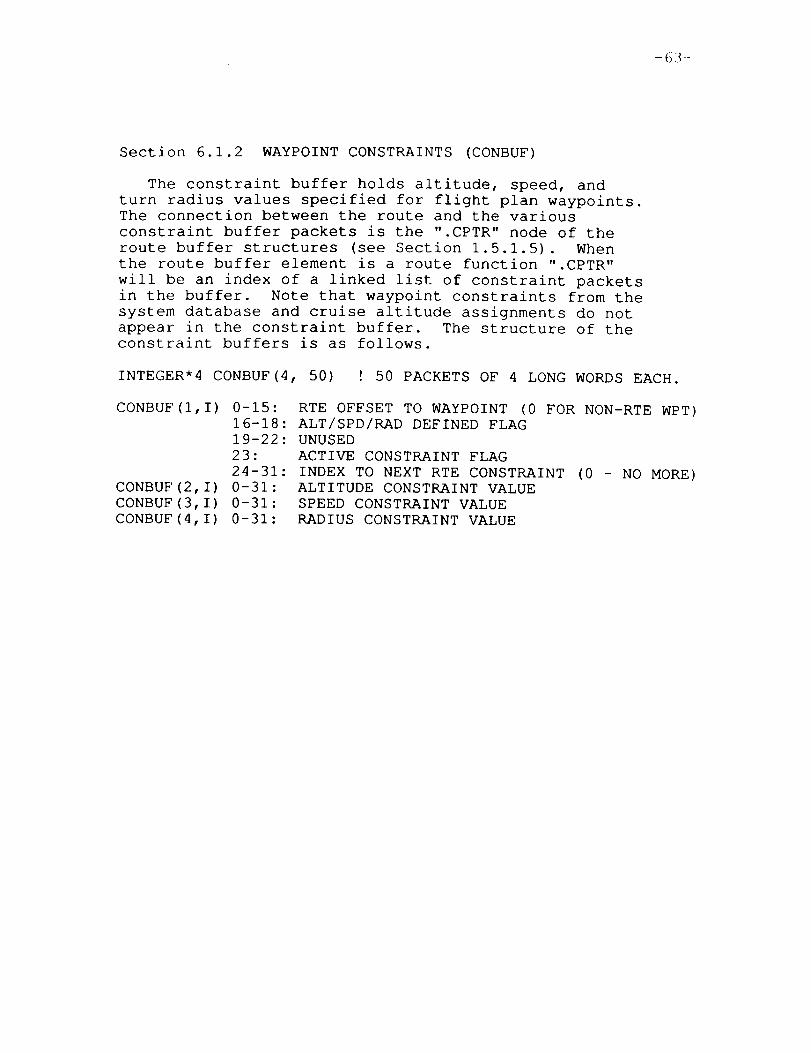
Section 6.1.2 WAYPOINTCONSTRAINTS (CONBUF)
The constraint buffer holds altitude, speed, andturn radius values specified for flight plan waypoints.The connection between the route and the variousconstraint buffer packets is the ".CPTR" node of the
route buffer structures (see Section 1.5.1.5). When
the route buffer element is a route function ".CPTR"
will be an index of a linked list of constraint packets
in the buffer. Note that waypoint constraints from the
system database and cruise altitude assignments do not
appear in the constraint buffer. The structure of the
constraint buffers is as follows.
INTEGER*4 CONBUF(4, 50) ! 50 PACKETS OF 4 LONG WORDS EACH.
CONBUF(I,I) 0-15: RTE OFFSET TO WAYPOINT (0 FOR NON-RTE WPT)16-18: ALT/SPD/RAD DEFINED FLAG
19-22: UNUSED
23: ACTIVE CONSTRAINT FLAG
24-31: INDEX TO NEXT RTE CONSTRAINT (0 - NO MORE)CONBUF(2,I) 0-31: ALTITUDE CONSTRAINT VALUE
CONBUF(3, I) 0-31: SPEED CONSTRAINT VALUE
CONBUF(4,I) 0-31: RADIUS CONSTRAINT VALUE


-65-
Section 6.1.3 HOLDING PATTERNDATA (HLDBUF)
The common block "HOLD" is a section of memory reservedfor holding pattern data created by hold page modules. Thememory allocation is defined in the file HLDBUF.MAR. Thisfile contains definitions for a four waypoint airway andfour GRPs used as hold waypoints. The format of theseblocks is the same as those used in AADCOM(see section1.5.1.1). The difference between the AADCOMand HLDBUFstructures is that AADCOMis predefined read-only memory andHLDBUF is a template filled in holding pattern procedures.
p_"4'EC_r',)G PAE_t. BL,a,N.w.N(-,i ._:*LM_-"T2,
Ck)U\ INT[NTIONALLY BLAN_


-67-
Section 6.1.4 PILOT DEFINED WAYPOINTS (PPT WPT)
The pilot defined waypoint buffer is used to save
information for waypoints created through calls to
the function MAKE WPT. Pilot waypoints are made for
runway selection, aircraft position reference, bearing/
range from reference point, and absolute position
selection. The Fortran allocation is shown below.
STRUCTURE /PPTS/
CHARACTER*5 NAME
BYTE BITS
REAL LAT, LON, ALT, SPD
CHARACTER*f6 TEXT
END STRUCTURE
RECORD /PPTS/ PPT WPT(20)
The ".BITS" node of the structure is set to indicate
when altitude and speed have been supplied for the pilot
waypoint. Bit #0 is set for altitude definition and bit
#i is set for speed definition. The ".TEXT" node is set
to the CDU command string entered by the pilot which
caused the pilot waypoint creation. This text may be
viewed on the NAV DATA page of the CDU.

-69-
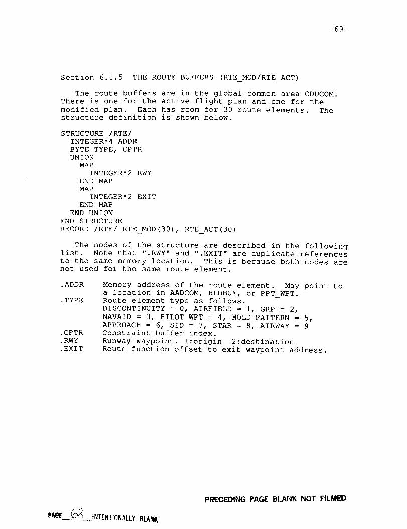
Section 6.1.5 THE ROUTEBUFFERS (RTE MOD/RTEACT)
The route buffers are in the global common area CDUCOM.There is one for the active flight plan and one for themodified plan. Each has room for 30 route elements. Thestructure definition is shown below.
STRUCTURE/RTE/INTEGER*4 ADDR
BYTE TYPE, CPTR
UNION
MAP
INTEGER* 2 RWY
END MAP
MAP
INTEGER* 2 EXIT
END MAP
END UNION
END STRUCTURE
RECORD /RTE/ RTE MOD(30), RTE ACT (30)
The nodes of the structure are described in the following
list. Note that ".RWY" and ".EXIT" are duplicate references
to the same memory location. This is because both nodes arenot used for the same route element.
.ADDR
.TYPE
.CPTR
.RWY
.EXIT
Memory address of the route element. May point toa location in AADCOM, HLDBUF, or PPT WPT.
Route element type as follows.
DISCONTINUITY = 0, AIRFIELD = i, GRP = 2,
NAVAID = 3, PILOT WPT = 4, HOLD PATTERN = 5,
APPROACH = 6, SID = 7, STAR = 8, AIRWAY = 9Constraint buffer index.
Runway waypoint, l:origin 2:destination
Route function offset to exit waypoint address.
PRECEDING PAGE BLANK NOT FILMED


-71-
Section 6.1.6 THE WAYPOINT BUFFERS (WPT MOD/WPT ACT)
The waypoint buffers contain the actual waypoint data
which defines the entire flight plan. WPT ACT is used for
the active flight plan while WPT MOD has the path which
is under modification. WPT MOD is re-created each time
a flight plan change is entered on the CDU. The waypoint
buffer is actually an expansion of the data already exist-
ing in the route buffer• Each route element is replaced
by one or more waypoints having any constraints defined
by CONBUF (see section 1.5.1.2), the cruise altitude, or
AADCOM predefinition. A number of waypoint buffer
parameters are computed from the geometry of the waypoints
taken from the expansion process. This "Path Definition"
phase, performed by the procedure PATHDF, starts when the
expansion process is complete. The structure template of
the waypoint buffers is shown below followed by a
description of each of the parameters.
STRUCTURE /WPTS/
CHARACTER*5 NAME
BYTE DMA, SOURCE, PHASE, ALTF, SPDF, RADF, FILL
INTEGER*4 RNAV, ETA
REAL LAT, LON, ALT, GS, TIME, CCD
REAL ARC2, DTT, RAD, BRNG, ANGLE, ERAD, PPD
REAL WPV(3), TCV(3), NMV(3)
REAL IAS, TCLAT, TCLON, WSPD, WDIR, MGVR, TDEV, FPAEND STRUCTURE
RECORD /WPTS/ WPT ACT(30), WPT MOD(30)
•NAME
.DMA
•SOURCE
.PHASE
.ALTF
.SPDF
.RADF
.FILL
.RNAV
.ETA
.LAT
.LON
.ALT
.GS
.TIME
.CCD
Waypoint name.
I:DMA turn start, 2:DMA turn stop, else 0.
Index into route buffer indicating the element
the waypoint was expanded from.
Phase of flight; l:climb 2:cruise 3:descent
0:undefined
Altitude defined flag; 0:undefined l:explicit
definition (AADCOM, PPT WPT, CONBUF), 2:implicit
defintion (cruise alt,TPOS ' updatable wpt). If
equal 2, shown in small font on LEGS page.
Speed definition flag; see .ALTF
Radius definition flag; 0:computed l:assigned
Keeps remaining nodes on long word boundary.
Radio navigation aid address pointer.
Estimated time of arrival (seconds past midnight)•
Waypoint latitude (deg).
Waypoint longitude (deg).
Waypoint altitude (ft).
Waypoint ground speed (kt).
Leg time from last waypoint (seconds)•
Turn center to turn center distance (ft).
PRECE[:),I[iG PAGE BI.A_K NO'I" FI,LMIED
-72-
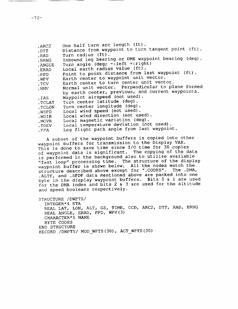
.ARC2
.DTT
.[tAD•BRNG•ANGLE•ERAD.PPD.WPV• TCV•NMV
.IAS
.TCLAT
.TCLON
.WSPD
.WDIR
.MGVR
.TDEV
.FPA
One half turn arc length (ft).Distance from waypoint to turn tangent point (ft).Turn radius (ft).Inbound leg bearing or DMEwaypoint bearing (deg).Turn angle (deg; -:left +:right)Local earth radius value (ft).Point to point distance from last waypoint (ft).Earth center to waypoint unit vector.Earth center to turn center unit vector•Normal unit vector. Perpendicular to plane formed
by earth center, previous, and current waypoints.
Waypoint airspeed (not used)•
Turn center latitude (deg).
Turn center longitude (deg).
Local wind speed (not used).
Local wind direction (not used)•
Local magnetic variation (deg).
Local temperature deviation (not used).
Leg flight path angle from last waypoint.
A subset of the waypoint buffers is copied into other
waypoint buffers for transmission to the Display VAX.
This is done to save time since I/O time for 30 copies
of waypoint data is significant. The copying of the data
is performed in the background also to utilize available
"fast loop" processing time. The structure of the display
waypoint buffer is shown below. All the nodes match the
structure described above except for ".CODES". The .DMA,
.ALTF, and .SPDF data mentioned above are packed into one
byte in the display waypoint buffers• Bits 0 & 1 are used
for the DMA index and bits 2 & 3 are used for the altitude
and speed booleans respectively.
STRUCTURE /DWPTS/
INTEGER*4 ETA
REAL LAT, LON, ALT, GS, TIME, CCD, ARC2, DTT, RAD, BRNG
REAL ANGLE, ERAD, PPD, WPV(3)
CHARACTER*5 NAME
BYTE CODES
END STRUCTURE
RECORD /DWPTS/ MOD WPTS(30), ACT WPTS(30)

-73-
Section 6.2 FLIGHT PLAN DATA PROCESSING
This section covers the internal operations performedon the flight plan data buffers. The 23 modules describedhere are contained in four files named EXECUTE.FOR,XLAT RTE.FOR, PATHDF.FOR, CONST.FOR. These modules usethe constraint buffer, navigation database, holding patterndata, pilot waypoint buffer, and the route buffer to createa provisional waypoint buffer which, upon pilot acceptance,becomes the active waypoint buffer.
The various clearance pages of the CDU have three modesof operation; original clearance, modified clearance, andactive clearance. The current mode is shown with the firstthree characters of the title line of clearance pages asfollows.
" " - orignal clearance"MOD" - modified clearance"ACT" - active clearance
The original clearance mode is active by default uponstarting the system or when the origin airfield is enteredon the ROUTEpage of the CDU. At this time RTE MODhasthe provisional flight plan and RTE ACT is undefined. Oncethe original clearance is EXECuted by the pilot the modebecomes ACT. At this time RTE MODand RTE ACT both containthe active flight plan. When changes are made to the activeplan the CDU mode becomes MOD. RTE ACT will contain theactive flight plan being used by guTdance, however the CDUshows the modified flight plan stored in RTE MOD.
Creation of a new "MOD" waypoint buffer is started whena CDU page handler receives a flight plan input and callsthe procedure DEMODE. Acceptance of the new flight plancan be automatic, depending on DEMODEparameters, or mayrequire pilot interaction. The pilot may however choose toreject the modified route and return to the last active plan.These operations are performed by the modules EXECUTEandREJECT.

-75-
Section 6.2.1 CONSTRAINTBUFFER USAGE
The constraint buffer is used to store altitude, speed,
and turn radius constraints for route waypoints. The
constraints are entered manually on the CDU through the
LEGS page. The format of this buffer is described in
section 1.5.1.2. Seven procedures perform various oper-
ations on the constraint buffer. Module descriptions of
each are provided on the following pages.

-76-
MODULENAME:FILE NAME:PROCESS:CALLED BY:CALLING SEQUENCE:
CLEAN CONCONST.FORSLOWEXECUTE, REJECTCALL CLEAN CON
PURPOSE:TO identify unused packets of the constraint buffer.
DESCRIPTION:This module performs clean-up on the CDU constraint
buffer. When a flight plan is executed or changes to the
active flight plan have been rejected, both the "ACT" and"MOD" route buffers are identical. At this time "CLEAN CON"
is called to identify which of the 50 constraint buffer--
packets of data are actually used. All others are marked as
free for future use while the used packets are flagged as
active constraints.
A 50 byte array of booleans (USED) is initialized as false
(not used). Each ".CPTR" pointer is followed into the linked
list of constraints. As each constraint is found the "active
constraint" bit is set and the corresponding USED byte is set
true. When finished, the first long word of each constraint
packet not denoted as used is cleared to designate it as
available.
GLOBAL REFERENCES:
ARRAYS
CONBUF* CONBYT RTE CNT
RECORD ARRAYS
RTE MOD
FUNCTIONS AND SUBROUTINES
CLRBUF

-77-
MODULENAME:FILE NAME:PROCESS:CALLED BY:CALLING SEQUENCE:
COPY CONCONS_.FORSLOWKILL CON, NEWCONNEWYNDEX= COPYCON(OLD INDEX)
PURPOSE:To copy a constraint list to other free constraint
buffer locations.
DESCRIPTION:This function is called to copy a constraint list starting
at the packet indicated by the OLD INDEX input parameter.The data is copied to free packets in the constraint bufferand the index of the new list is returned as the functionvalue.
The linked list pointers are followed and for eachold constraint packet a call to FIND_EMPTY is made to get anavailable block. The old data is copied to the new locationsand the "active constraint" bit of the new data is cleared.
GLOBAL REFERENCES:
ARRAYSCONBUFCONBYT
FUNCTIONS AND SUBROUTINESFIND EMPTY LIB$MOVC3

-78-
MODULENAME:FILE NAME:PROCESS:CALLED BY:CALLING SEQUENCE:
FIND EMPTYCONST.FORSLOWCOPY CON, HLD POS, NEWCONINDEX = FIND EMPTY()
PURPOSE:TO locate an available constraint packet.
DESCRIPTION:This function returns the index of the first free packet
in the constraint buffer. The first long word of eachpacket is examined until an available set is found (equal 0).If all 50 constraints are used the CDU error code is set to#4 and a return to the caller's caller is performed.
GLOBAL REFERENCES:
VARIABLESERCODE*
ARRAYSCONBUF
FUNCTIONSAND SUBROUTINESRET

-79-
MODULENAME:FILE NAME:PROCESS:CALLED BY:CALLING SEQUENCE:
GET CONCONST.FORSLOWRTE, XLAT RTEGET_CON(RTE_PTR,OFFSET, WPT_PTR)
PURPOSE:TO store constraints into waypoint buffer locations.
DESCRIPTION:
This procedure is called with an index into the route
buffer (RTE PTR) of the route element containing a par-
ticular waypoint. If the route element is a route function
then the database offset is also supplied. Any constraint
data existing for the waypoint is fetched and copied to the
waypoint buffer for the waypoint designated by the parameter
list index WPT PTR. The waypoint buffer flags .ALTF, .SPDF,
and .RADF are set appropriately.
Note that when the route element is a route function, the
constraint buffer contains a linked list which must be
followed until a matching offset value is found or the end
of the list is encountered.
GLOBAL REFERENCES:
ARRAYS
CONBUF CONBYT CONWRD
RECORD ARRAYS
RTE MOD WPT MOD*
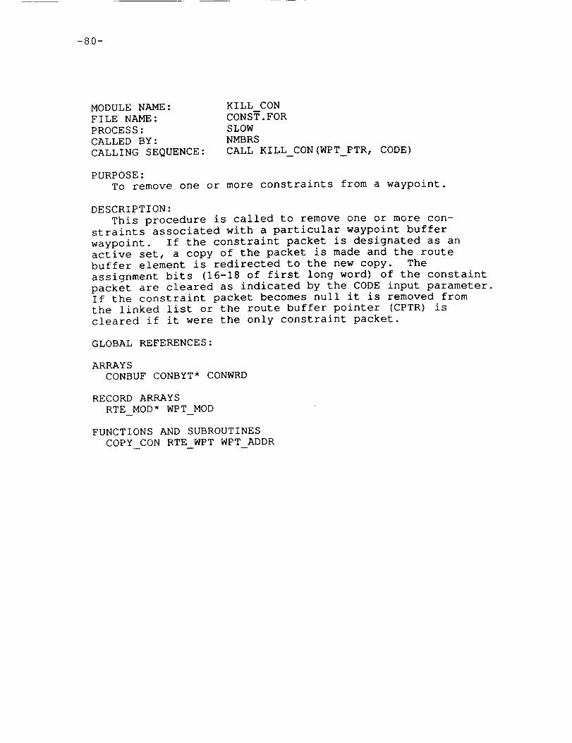
-80-
MODULENAME:FILE NAME:PROCESS:CALLED BY:CALLING SEQUENCE:
KILL CONCONST.FORSLOWNMBRSCALL KILL_CON(WPT_PTR, CODE)
PURPOSE:TO remove one or more constraints from a waypoint.
DESCRIPTION:This procedure is called to remove one or more con-
straints associated with a particular waypoint bufferwaypoint. If the constraint packet is designated as anactive set, a copy of the packet is made and the routebuffer element is redirected to the new copy. Theassignment bits (16-18 of first long word) of the constaintpacket are cleared as indicated by the CODE input parameter.If the constraint packet becomes null it is removed from
the linked list or the route buffer pointer (CPTR) is
cleared if it were the only constraint packet.
GLOBAL REFERENCES:
ARRAYS
CONBUF CONBYT* CONWRD
RECORD ARRAYS
RTE MOD* WPT MOD
FUNCTIONS AND SUBROUTINES
COPY CON RTE WPT WPT ADDR__ m --

-81-
MODULE NAME:
FILE NAME:
PROCESS:
CALLED BY:
CALLING SEQUENCE:
NEW CON
CONST.FOR
SLOW
NMBRS, XFER CON
variable (see below)
PURPOSE:
To insert waypoint constraints into the constraint buffer.
DESCRIPTION:
This module is called to add a constraint to a waypoint
on the flight plan. The waypoint may have other constraints
already defined. Two calling sequences exist for this
module, as shown below. The module P LIST is used to determine
which calling sequence was used.
CALL NEW CON(WPT_PTR, V TYPE, VALUE)
CALL NEW_CON(,V TYPE, VALUE, RTE_PTR, RTE_OFF)
WPT PTR
V TYPE
VALUE
RTE PTR
RTE OFF
Index into waypoint buffer of selected waypoint.
Type of constraint: l=altitude 2=speed 3=radius
Constraint value.
Rte buffer index of rte element owning selected wpt.
Offset into rte function for rte type waypoint.
The constraint pointer of the route element corresponding
to the selected waypoint is fetched. It is used to determine
if a constraint packet already exists for the waypoint. Ifsaved constraints for the route element have the "active" bit
set, a duplicate copy is made so modifications may be made.
When the pointer points to a linked list, the links must be
followed to determine the existence of data for a particular
waypoint. When constraint data already exists, the fields of
the packet are simply updated. Otherwise a new packet is
created. When the waypoint is part of a route function
which has other waypoint constraints, the new packet is
inserted into the linked list chain.
GLOBAL REFERENCES:
ARRAYS
CONBUF* CONBYT* CONWRD*
RECORD ARRAYS
RTE MOD* WPT MOD
FUNCTIONS AND SUBROUTINES
COPY CON FIND EMPTY P LIST RTE WPT WPT ADDR

-82-
MODULENAME:FILE NAME:PROCESS:CALLED BY:CALLING SEQUENCE:
XFER CONCONST.FORSLOWMERGE, NEWENTRYCALL XFER_CON(FROM,OFFSET, TO)
PURPOSE:TO transfer constraint data.
DESCRIPTION:This procedure is called to transfer existing waypoint
constraints to another waypoint. Both waypoints must be partof a route function which is indicated by the route bufferpointer FROM/TO and the route function offset, OFFSET.This procedure is used by routines which split a single routefunction into a repeated pair of route functions with differententry/exit points.
GLOBAL REFERENCES:
ARRAYSCONBUFCONBYTCONWRD
RECORDARRAYSRTE MOD
FUNCTIONS AND SUBROUTINESNEWCON
-83-
Section 6.2.2 ROUTETRANSLATIONAND PATH DEFINITION
The modified route buffer (RTE MOD) and other basicflight plan database elements are combined to form theprovisional waypoint buffer (WPT MOD). The procedures onthe file XLAT RTE.FOR perform this task. Once the routebuffer has been translated into a basic waypoint buffer, thepath definition procedures contained in the file PATHDF.FORare called to create the mathematical constructs associatedwith using the waypoint buffer as a guidance buffer. Thetranslation and definition process is started by a call tothe procedure DEMODEany time a flight plan modification ismade on the CDU. The following pages contain the moduledescriptions for these routines.

-84-
MODULENAME:FILE NAME:PROCESS:CALLED BY:CALLING SEQUENCE:
CREATEBUFEXECUTE.FORSLOWDEMODE,EXECUTECALL CREATE_BUF(COUNT,WPT_BUF, DSP_BUF)
PURPOSE:To move selected portions of the waypoint buffer to the
display waypoint buffer.
DESCRIPTION:This procedure is called with a waypoint count and one
of the waypoint buffers as inputs. It stores portions ofthe waypoint buffer into one of the display waypointbuffers as the sole output parameter.
For each waypoint sixty-eight consecutive bytes of data
starting at the .ETA parameter are moved to the display
buffer. Then the .DMA, .ALTF, and .SPDF data is packed into
the .CODES bytes of the display buffer.
GLOBAL REFERENCES:
FUNCTIONS AND SUBROUTINES
LIB$MOVC3
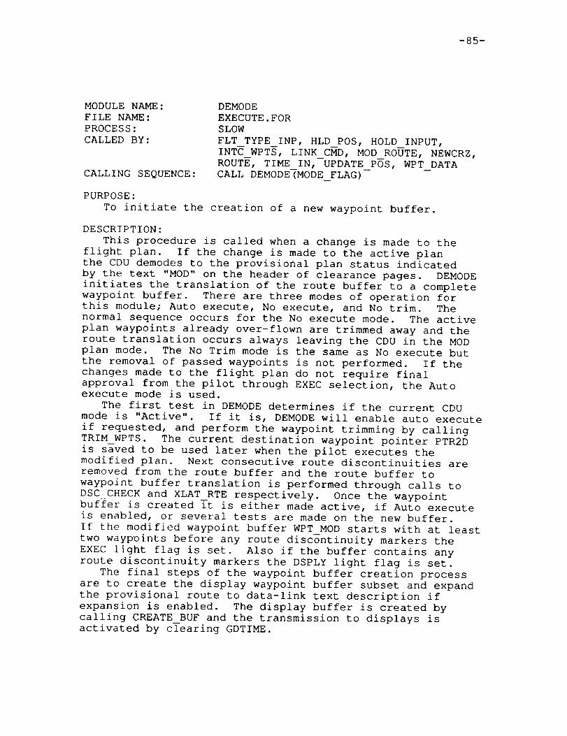
-85-
MODULENAME:FILE NAME:PROCESS:CALLED BY:
CALLING SEQUENCE:
DEMODEEXECUTE.FORSLOWFLT TYPE INP, HLD_POS, HOLD INPUT,INTC WPTS, LINK CMD, MODROUTE, NEWCRZ,ROUTE, TIME IN,--UPDATE POS, WPT DATACALL DEMODE(MODEFLAG)
PURPOSE:TO initiate the creation of a new waypoint buffer.
DESCRIPTION:This procedure is called when a change is made to the
flight plan. If the change is made to the active planthe CDU demodes to the provisional plan status indicatedby the text "MOD" on the header of clearance pages. DEMODEinitiates the translation of the route buffer to a completewaypoint buffer. There are three modes of operation forthis module; Auto execute, No execute, and No trim. Thenormal sequence occurs for the No execute mode. The activeplan waypoints already over-flown are trimmed away and theroute translation occurs always leaving the CDU in the MODplan mode. The No Trim mode is the same as No execute butthe removal of passed waypoints is not performed. If thechanges made to the flight plan do not require finalapproval from the pilot through EXEC selection, the Autoexecute mode is used.
The first test in DEMODEdetermines if the current CDUmode is "Active". If it is, DEMODEwill enable auto executeif requested, and perform the waypoint trimming by callingTRIM WPTS. The current destination waypoint pointer PTR2Dis saved to be used later when the pilot executes themodified plan. Next consecutive route discontinuities areremoved from the route buffer and the route buffer towaypoint buffer translation is performed through calls toDSC CHECK and XLAT RTE respectively. Once the waypointbuffer is created Tt is either made active, if Auto executeis enabled, or several tests are made on the new buffer.If the modified waypoint buffer WPTMOD starts with at leasttwo waypoints before any route discontinuity markers theEXEC light flag is set. Also if the buffer contains anyroute discontinuity markers the DSPLY light flag is set.
The final steps of the waypoint buffer creation processare to create the display waypoint buffer subset and expandthe provisional route to data-link text description ifexpansion is enabled. The display buffer is created bycalling CREATEBUF and the transmission to displays isactivated by clearing GDTIME.

-86-
GLOBAL REFERENCES:
VARIABLESCDU CMD GDTIME* LT DSPY* LT EXEC* MODCNTPMODE*PTR2DSAVPTR*
ARRAYSRTE CNT
RECORDARRAYSMODWPTS RTE MODWPT MOD
FUNCTIONS AND SUBROUTINESCREATE BUF DSC CHECKEXECUTEEXPAND_RTETRIM_WPTSXLAT_RTE
C

-87-
MODULE NAME:
FILE NAME:
PROCESS:
CALLED BY:
CALLING SEQUENCE:
DSC WPT
XLAT RTE.FOR
SLOW
XLAT_RTE, RTE
CALL DSC_WPT(WPT_INDEX, RTE_INDEX)
PURPOSE:
TO insert a route discontinuity into the waypoint buffer.
DESCRIPTION:
This subroutine is called to insert a discontinuity
marker into the flight plan. One is inserted only if the
previous waypoint entry was not also a discontinuity marker
and there is room in the waypoint buffer. The discontinuity
is associted with the route buffer via the source index "I"
GLOBAL REFERENCES:
RECORD ARRAYS
WPT MOD*

-88-
MODULENAME:FILE NAME:PROCESS:CALLED BY:CALLING SEQUENCE:
FIND CCDPATHDF.FORSLOWPATHCCD = FIND CCD(TO ADJUST)
PURPOSE:
TO compute the CCD parameter in the waypoint buffer.
DESCRIPTION:
The turn center to turn center distance (CCD) differs
from the waypoint to waypoint distance for "Pass By"
waypoints. The adjusment at each end of the leg is
the tangent distance minus half the turn arc length
(DTT-ARC2). The "From Waypoint" adjustment is computed
in this procedure and the "To Waypoint" adjustment is
passed as a parameter to avoid DMA arc entry waypoint
testing.Checks are made to assure that the leg being processed
has proper geometry at both ends. When the sum of the
tangent distance becomes larger than the point to point
distance a "Bad Radius" situation has occured. This
means a "Pass By" turn is to large for the given leg
length. The offending turn radius is set to zero and
the path definition waypoint index is reset to force
the calling module to recompute parameters using the
new turn radius.
GLOBAL REFERENCES:
VARIABLES
ERCODE*
RECORD ARRAYS
WPT MOD

-89-
MODULENAME:FILE NAME:PROCESS:CALLED BY:CALLING SEQUENCE:
PURPOSE:
LOCAL ERADPATHDF.FORSLOWPATH, NEWPOS, POINTSCOMMON/PTHCOM/ LAT_FEET, LON FEET, RAD
CALL LOCAL_ERAD(ALT, SIN_LAT,--COS_LAT)
To compute local earth radius values.
DESCRIPTION:
This procedure uses the input parameter for waypoint
altitude, and sine/cosine of latitude to compute local
earth radius values. The computed values, returned through
common PTHCOM, are the earth radius to waypoint and the
number of feet per degree of both latitude and longitude.
GLOBAL REFERENCES:
VARIABLES
LAT FEET* LON FEET* RAD*

-90-
MODULENAME:FILE NAME:PROCESS:CALLED BY:CALLING SEQUENCE:
PATHPATHDF.FORSLOWPATHDFCALL PATH(START_INDEX, END_INDEX)
PURPOSE:TO compute flight plan parameters required by guidance
and display software.
DESCRIPTION:This procedure computes many of the guidance buffer
parameters associated with the aircraft flight plan, whichare contained in the structure "WPT MOD". Several of thestructure nodes are filled by "XLAT RTE" before calling thissubroutine. The following list shows which parameters of"WPT MOD" are computed. Some values are not computed for allwaypoints, therefore these exceptions are noted.
WPT MOD(I) " .XXX"LATLONPPDDTTARC2ANGLECCD
BRG
TCLAT
TCLON
FPA
TIME
ERAD
WPV
NMV
TCV
waypoint latitude
waypoint longitude
point to point distance
distance to tangent
one half arc length
turn angle
center to center distance
bearingturn center latitude
turn center longitude
flight path angle
delta time
local earth radius
waypoint vector
unit normal vector
turn center vector
INBOUND DMA WPTS ONLY
INBOUND DMA WPTS ONLY
ALL WPTS
ALL WPTS
ALL WPTS
ALL WPTS
ALL WPTS
ALL EXCEPT OUTBOUND DMA
ALL EXCEPT INBOUND DMA
ALL EXCEPT INBOUND DMA
ALL WPTS
ALL WPTS
ALL WPTS
ALL WPTS
ALL WPTS
ALL WPTS
PATHDF computes the guidance parameters in two passes
through the waypoint buffer. The exact mathematical
concepts invloved with the various parameters are dis-
cussed in Appendix A.
During the first pass the waypoint vectors (WPV), normal
vectors (NMV), point to point distances (PPD), and local
earth radius (ERAD) values are computed for each waypoint.
WPV and ERAD are computed by calls to XYZ and LOCAL ERAD
respectively. NMV is the cross product of the current and
previous waypoints WPV vectors. These WPV values are alsoused in combination with the ERAD value to compute PPD using
the arc length formula Arc_length = Radius * Angle_radians.
DMA waypoint repositioning occurs also during the first pass.

-91-
When PATHDF encounters a DMAentry waypoint, new latitude andlongitude values are computed from the turn center
previously stored as LAT/LON. The old LAT/LON values are
moved to the turn center locations (TCLAT/TCLON). The new
LAT/LON values are found from the turn center position,
bearing from turn center to new position, and the turn
radius which are all fetched from AADCOM and stored by
XLAT RTE prior to calling PATHDF.
The remaining guidance parameters are computed during the
second pass through the waypoint buffer. None of the
parameters for the second pass are computed for the first
waypoint. Several are not assigned for the last waypoint
(ANGLE, ARC2, DTT, TCV, TCLAT, TCLON). There are three
guidance buffer parameters that are handled identically
for all types of waypoints. These are RAD, FPA, and TIME.
For a DMA entry waypoint only the CCD value is computed.
The TCV, CCD, and previous waypoints ARC2 parameters are
computed when the waypoint is a DMA arc exit waypoint. For
standard waypoints the BRNG, CCD, ANGLE, ARC2, DTT, TCV,TCLAT, and TCLON values are set.
When starting and ending tangent distances (DTT) for a
leg are large enough to overlap, a "Bad Radius" turn exists.
The module FIND_CCD makes a zero radius turn at the offending
waypoint and signals PATHDF to recompute guidance parameters
for the new turn radius. The waypoint with the redefined
turn radius appears on the LEGS page of the CDU with anasterisk.
GLOBAL REFERENCES:
VARIABLES
COS LAT LAT FEET LON FEET RAD SIN LAT
RECORD ARRAYS
WPT MOD*
FUNCTIONS AND SUBROUTINES
FIND CCD GRID LOCAL ERAD MTH$ASIN MTH$ASIND MTH$ATAN2MTH$ATAND2 SCOSD UVC VCP VDP VMG XYZ

-92-
MODULENAME:FILE NAME:PROCESS:CALLED BY:CALLING SEQUENCE:
PATHDFPATHDF.FORSLOWXLAT RTECALL PATHDF
PURPOSE:TO initiate path definition computations.
DESCRIPTION:This subroutine is the main driver of the path definition
process. Calls to "PATH" are made after delimiting groups ofconsecutive waypoints in the provisional waypoint structure"WPT MOD". Usually one call to "PATH" is made for theentire set of waypoints, however multiple calls are madewhen route discontinuities exist in the flight plan. Theeffect of this is to make several disjoint path segments inone waypoint buffer.
GLOBAL REFERENCES:
VARIABLESMODCNT
RECORDARRAYSWPT MOD
FUNCTIONS AND SUBROUTINESPATH
-93-
MODULENAME:FILE NAME:PROCESS:CALLED BY:CALLING SEQUENCE:
RTA TIMESXLAT RTE.FORSLOWXLAT RTECALL RTA TIMES
PURPOSE:TO set arrival times in the waypoint buffer.
DESCRIPTION:The Requested Time of Arrival (RTA) waypoint is located
in the waypoint buffer. When the waypoint no longerexists the RTA parameters are reset. Otherwise the selectedRTA time is assigned to the RTA waypoint and the remainingwaypoint times are set according to the stored leg timevalues.
GLOBAL REFERENCES:
VARIABLESMODCNTRTA INDX* RTA TM RTA WPT*
RECORDARRAYSWPT MOD*

-94-
MODULENAME:FILE NAME:PROCESS:CALLED BY:CALLING SEQUENCE:
RTEXLAT RTE.FORSLOWXLAT RTECALL--RTE(RTE__INDEX, WPT__INDEX)
PURPOSE:
To store route waypoints in the waypoint buffer.
DESCRIPTION:
This subroutine is called by "XLAT RTE" when a route
function is encountered while translating the route buffer.
All the waypoints for a complete route function (both entry
and exit waypoints defined) are placed in the WPT buffer
through calls to "WPT", except for the entry waypoint.
Since the route buffer defines the entry WPT as a separate
route buffer element the entry waypoint will already be placed
in the waypoint buffer when the route function is being
processed. The only thing "RTE" does for the entry waypoint
is the search of the constraint buffer mentioned below.
When the route function is not an airway, the speed,
altitude, and DMA turn information is fetched from the
navigation database (AADCOM). The last processing of each
waypoint consists of calling GET CON to extract constraint
data. Note that previously stored AADCOM values will be
overwritten if higher priority constraint buffer values
exist.
When a route function's entry waypoint has not been
defined a discontinuity will already exist in the waypoint
buffer. In this case the exit waypoint only is saved
following the discontinuity. For the reverse situation a
discontinuity is stored after the existing entry waypoint
for the missing exit waypoint. When niether is defined one
discontinuity is placed in the waypoint buffer for the
entire route function.
A distinction is made between airways and other route
functions (SID STAR APPROACH HOLD). Each airway waypoint
is assigned a "cruise" phase of flight and the current
cruise altitude, which may be overridden later during the
constraint buffer fetches. For non-airway route functions,
SIDs are assigned the "climb" phase of flight while others
are set to "descent". The altitude, speed, and turn
radius is fetched from the navigation database (AADCOM)
or the hold buffer (HLDBUF). The turn radius may contain
a zero which is a cue to the path definition routine to
compute the value. The fetched altitude is also used as
a flag. When negative, the current waypoint is a DMA turn
entry waypoint and the following waypoint is a DMA turn
exit waypoint. The DMA bearing and turn angle are also
fetched from the database in these cases.

-95-
GLOBAL REFERENCES:
VARIABLESCRZALT
RECORDARRAYSRTE MODWPT MOD*
FUNCTIONS AND SUBROUTINESBOUNDSDSC WPT GET CON GET LONG GET REAL TYPE WPT WPT

-96-
MODULENAME:FILE NAME:PROCESS:CALLED BY:CALLING SEQUENCE:
TRIM WPTSEXECUTE.FORSLOWDEMODE,ADD WPT, DIRECTCALL TRIM WPTS(NEXT_WPT_INDEX)
PURPOSE:TO remove passed waypoints from the active flight plan.
DESCRIPTION:This procedure is called to eliminate the beginning way-
points from the route buffer which have already been passedon the active flight plan. When the deletion splits aroute function a new entry waypoint is created.
The input parameter NEXT WPT INDEX points to the endwaypoint in the waypoint buffer of the leg which is tobecome the first leg of the route. The route buffer element
corresponding to the waypoint before the chosen waypoint isexamined to determine its type. If the route element is a
single waypoint, all the route elements up to and including
the tested one are removed from the route buffer (RTE MOD)
by calling KILL. When a route function is encountered the
procedure NEW ENTRY is used to split the route function
into the portTon that is to be saved. Then the prior
elements are removed by calling KILL.
GLOBAL REFERENCES:
RECORD ARRAYS
RTE MOD WPT MOD
FUNCTIONS AND SUBROUTINES
BOUNDS KILL NEW ENTRY RTE WPT WPT ADDR
-97-
MODULENAME:FILE NAME:PROCESS:CALLED BY:CALLING SEQUENCE:
WPTXLAT RTE.FORSLOWXLAT RTE, RTECALL WPT(RTE_INDEX, WPT_INDEX, ADDR, TYPE)
PURPOSE:TO store waypoint data into the waypoint buffer•
DESCRIPTION:This subroutine is called to place a waypoint in the next
available position of the modified waypoint buffer (WPT MOD).The following items are stored for each waypoint.
•NAME•LAT. LON.RNAV•MGVR• SOURCE
5 character WPT name padded with blanks on the right.Waypoint latitude position•Waypoint longitude position•database address pointer to local navaid.Local magnetic variation value.Index into rte buffer which associates a waypointwith the rte buffer data that caused its creation.
If the waypoint is a pilot defined waypoint four other itemsmay be set.
.ALT
.ALTF
.GS
.SPDF
Altitude constraint.Altitude definition flag.Ground speed constraint•Speed definition flag.
The data is fetched using the input address parameterwhich is a pointer into AADCOM, HLDBUF, or PPT WPT. TheTYPE parameter determines how the data is fetched. The .LAT,.LON, .MGVR, and •SOURCEparamters are set identically forall types. Other parameters are set as follows.
AIRFIELD:GRP:
NAVAID:PILOT PT:
4 character name / no navaid pointer (0).
5 character name / navaid fetched from GRP
block in database (ADDR+I4).
3 character name / navaid reference is self.
5 character name / no navaid / alt & spd data
fetched from pilot buffer (PPT WPT). flags
set according to pilot waypoint type, POS,
PPT, or RWY.

-98-
GLOBAL REFERENCES:
VARIABLESERCODE*
RECORDARRAYSWPT MOD*
FUNCTIONS AND SUBROUTINESGET BYTE GET CHAR GET LONG GET REAL GET WORDMAGVAR

-99-
MODULENAME:FILE NAME:PROCESS:CALLED BY:CALLING SEQUENCE:
XLAT RTEXLAT RTE.FORSLOWDEMODE,HLD POSCALL XLAT RTE
PURPOSE:TO translate the route buffer into a waypoint buffer.
DESCRIPTION:This subroutine translates the route buffer "RTE MOD"
into the equivalent waypoint buffer "WPT MOD". The--routebuffer consists of waypoints, route functions, and routediscontinuity markers. The waypoint buffer contains justwaypoints and discontinuity markers. First, the entirememory area reserved for WPT MOD is cleared to initializeall parameters to zero. Once this is finished each item inRTE MOD is examined to determine the appropriate action toperform corresponding to its type. The last step is to call
PATHDF to compute flight plan parameters for each waypoint.
The conversion is done by indexing through each element
of the modified route buffer (RTE MOD). If the route
element is a route function the p_ocedure RTE is called to
store the data for each waypoint contained on the route
function. If the element is a discontinuity marker a call
to DSC_WPT is made. The last possibility is a single
waypoint element. The procedure WPT is called to store the
basic waypoint data followed by a call to GET CON to fetch
any ALT/SPD/RAD constraint data. If no altitude constraint
was found in the constraint data the cruise altitude, if
entered, is assigned to the waypoint.
Once stepping through the route buffer is finished a few
miscellaneous operations are performed. The created way-
point buffer is examined to see if takeoff and landing
runways exist. If not the respective runway addresses are
cleared (AIRPTS(2,1), AIRPTS(2,2)). The waypoint buffer
may not end in a discontinuity marker so the buffer is
checked and the discontinuity is removed if present.
Finally, the procedures PATHDF and RTA TIMES are called
to compute the remaining guidance parameters.
GLOBAL REFERENCES:
VARIABLES
CRZALT MODCNT* RTA WPT
ARRAYS
AIRPTS* RTE CNT
RECORD ARRAYS
RTE MOD WPT ACT WPT MOD
FUNCTIONS AND SUBROUTINES
CLRBUF DSC WPT GET CON PATHDF RTA TIMES RTE WPT

-i01-
Section 6.2.3 EXECUTE/REJECTTHE MODIFIED FLIGHT PLAN
When flight plan entries are complete, either for theoriginal clearance or a modified active plan, the pilotmust choose between executing or rejecting the provisionalflight plan. The EXEC button of the CDU will be lit whenexecution is allowed. If pressed, the provisional planbecomes the new active flight plan. At this time the MODbuffers will be identical to their active counterparts(RTE MOD/ WPT MOD- RTE ACT/WPT ACT) and the CDU clearancepages will display "ACT" as the first part of their titleline. When the clearance entries were made as modificationsto an existing active flight plan the "Erase" option isgiven. The text "ERASE>" appears on the right hand sideof the last display line of the CDU when on the ROUTE,LEGS, or TIME pages. If the pilot presses the line selectkey adjacent the erase prompt, the changes to the clearanceare removed and the "ACT" mode is returned.
Three modules handle execution and rejection of theprovisional flight plan. Their descriptions are providedon the following pages.
-102-
MODULENAME:FILE NAME:PROCESS:CALLED BY:CALLING SEQUENCE:
EXECUTEEXECUTE.FORSLOWCDUEXC, DEMODECALL EXECUTE(MODE)
PURPOSE:To activate the current provisional flight plan.
DESCRIPTION:This procedure activates the provisional flight plan
by copying the MOD route and waypoint buffers to theirACT counterparts• A number of simple steps are perfomedwhen execution is required. They are enumerated belowin the appropriate sequence• Afterward more detailedexplanation is provided for those parts requiring it.
If a "POS" update waypoint starts the new plan, makeone last update of the waypoint by calling UPDATE_POS.
Signal guidance software (HVGUID) that the flight plan istemporarily invalid by clearing the 2D, 3D, and 4Dguidance flags•
If not called with Auto execute flag, identify next "To"waypoint and reset some phase of flight flags.
Copy the modified route buffer (RTE_MOD) to the active
buffer (RTE ACT). If a discontinuity is encountered
terminate the plan at that point.
Copy the modified waypoint buffer (WPT_MOD) to the
active (WPT ACT). Check altitude and speed definitions
at each waypoint to determine possible guidance modes.
Process execution of holding pattern data if entered
by calling HOLD_SET.
Perform cleanup on the constraint buffer by calling
CLEAN CON.
• Enable guidance remode (SETGD = 2).
Save new active data which may be modified on next plan
changes; airfield info, cruise alt, RTA waypoint.
Fetch destination runway information from navigation
database (AADCOM).

-103-
If not Auto execute mode reset EXEC and DSPLY lightsand set the active guidance waypoint pointer (PTR2D)to the previously chosen "To" waypoint. Otherwisecheck if PTR2D should be set to the active hold waypoint.
Fill in active display waypoint buffer by callingCREATEBUF and flag display buffer transmission byclearing GDTIME.
Selecting a "To" waypoint can be complicated. Ifthere was no previous active flight plan the secondwaypoint is designated. If there was an active planseveral tests are made. When a current active leg ispart of a holding pattern the last PTR2D index is usedsince waypoint trimming is not used for holding pattern
changes (see DEMODE). When trimming was enabled the
pointer is initialized to the second waypoint. However
the second waypoint corresponds to the last active
waypoint when changes to flight plan started. The
airplane may cross waypoints while entries are being
made. When this situation occurs the pointer is advanced
along the flight plan as along as one-to-one correspondence
remains in the following waypoints.
GLOBAL REFERENCES:
VARIABLES
ACTCNT ACTCRZ* ANTLAT* ANTLON* CLBCHNG* COSRH CRZALT
CRZCHNG* DESCHNG* DESCHNGI* GDTIME* GSA* GUID2D* GUID3D*
GUID4D* HLD2D* LT DSPY* LT EXEC* MODCNT ORGRWY* PMODE*
POSTIME* PTR2D* RTA INDX RTA PTR* RWYHDG RWYLAT* RWYLEN*
RWYLON* RYELEV* SAVPTR* SETGD* SINRH TST3D* TST4D*
ARRAYS
AIRPTS RTE CNT*
RECORD ARRAYS
ACT WPTS RTE ACT* RTE MOD WPT ACT WPT MOD
FUNCTIONS AND SUBROUTINES
CLEAN CON CREATE BUF EXIT GET REAL HOLD SET SCOSD UPDATE POS
XLAT RTE

-104-
MODULENAME:FILE NAME:PROCESS:CALLED BY:CALLING SEQUENCE:
HOLD SETEXECUTE.FORSLOWEXECUTE, REJECTCALL HOLD SET(MODE)
PURPOSE:To setup active holding pattern data structures.
DESCRIPTION:This module is called upon the execution of a provisional
flight plan or the rejection of modifications to an existingactive plan. It determines if a holding pattern exists inthe active flight plan and sets up a pointer to the hold!FIX' waypoint and also saves its name. One other action istaken when the pattern is found, which will depend onwhether the call to HOLD SET was made from EXECUTEorREJECT. On execute, the hold pattern database set up byhold page software, is saved in local memory. On reject thesaved active database is restored to replace changes thatmay have been made to the holding pattern.
GLOBAL REFERENCES:
VARIABLESACTCNT HLD PTR* HLD WPT*
ARRAYSSTART
RECORDARRAYSWPTACT
FUNCTIONS AND SUBROUTINESLIBSMOVC3

-105-
MODULE NAME:
FILE NAME:
PROCESS:
CALLED BY:
CALLING SEQUENCE:
REJECT
EXECUTE.FOR
SLOW
LEGS, LEGS TIME, ROUTE
CALL REJECT
PURPOSE:
To remove all changes to the last active flight plan.
DESCRIPTION:
This module is called when the pilot chooses to reject
the changes made to the current active flight plan. The
following information sequentially lists the steps taken
to restore the active flight plan to the MOD buffers.
Set the CDU mode to "ACT" and clear POS update waypoint
flag (if one existed).
Copy the active waypoint buffer into its MOD buffer.
Copy the active route buffer into its MOD buffer.
Restore holding pattern parameters by calling HOLD SET.
Free unused constraint buffer locations by callingCLEAN CON.
Restore miscellaneous flight plan variables;
cruise alt, RTA waypoint.
airfields,
. Turn off EXEC and DSPLY lights.
Expand restored route buffer to data-link text bufferif enabled.
GLOBAL REFERENCES:
VARIABLES
ACTCNT ACTCRZ CDU CMD CRZALT* LT DSPY* LT EXEC* MODCNT*
ORGRWY PMODE* POSTIME* RTA INDX RTA PTR RTA WPT*
ARRAYS
AIRPTS* RTE CNT*
RECORD ARRAYS
RTE ACT RTE MOD* WPT ACT WPT MOD*
FUNCTIONS AND SUBROUTINES
CLEAN CON EXPAND RTE HOLD SET


-107-
Section 6.3 THE FLIGHT PLANNING PAGES
The CDU has numerous ways of generating and modifyingthe aircraft's flight plan. There are seven CDU pages
dedicated to this purpose, not including the phase of
flight or initialization pages which allow cruise altitude
selection. The following sections give a brief outline
of the usage for each page followed by descriptions of the
software modules used. A detailed functional description
of the CDU clearance pages will be provided in another
document to be provided by NASA's CDU requirements designer.
pA,I_.__._L,C__II'ITErlTI0t'IALLYBLANI&
PRECEDING PAGE BLANK NOT FILMED

-109-
Section 6.3.1 THE DEPARTURE/ARRIVAL PAGE
The DEPARTURE/ARRIVAL pages provide the flight crew
with departure and arrival information for the origin and
destination airports or for any other airport in the
navigation database (AADCOM). Also, these pages allow
the flight crew to insert departure and arrival route
elements into the route buffer by pressing the labeled
LSKs.The DEPARTURE/ARRIVAL INDEX page provides access to the
DEPARTURE subpage and the ARRIVAL subpage, where specific
information about each airport is displayed. On the
DEPARTURE subpage, all SIDs and runways listed in AADCOM
for the selected airport, are diplayed. On the ARRIVAL
subpage, all STARs, approaches and runways for the selected
airport are displayed. <SEL> and <ACT> bugs are displayed
next to the route elements which are part of the current
provisional or active flight plan. Refer to figures 6.1
and 6.2 on the following pages.
pIr@ECEgI._G PAGE t]LANK NOT FILMED

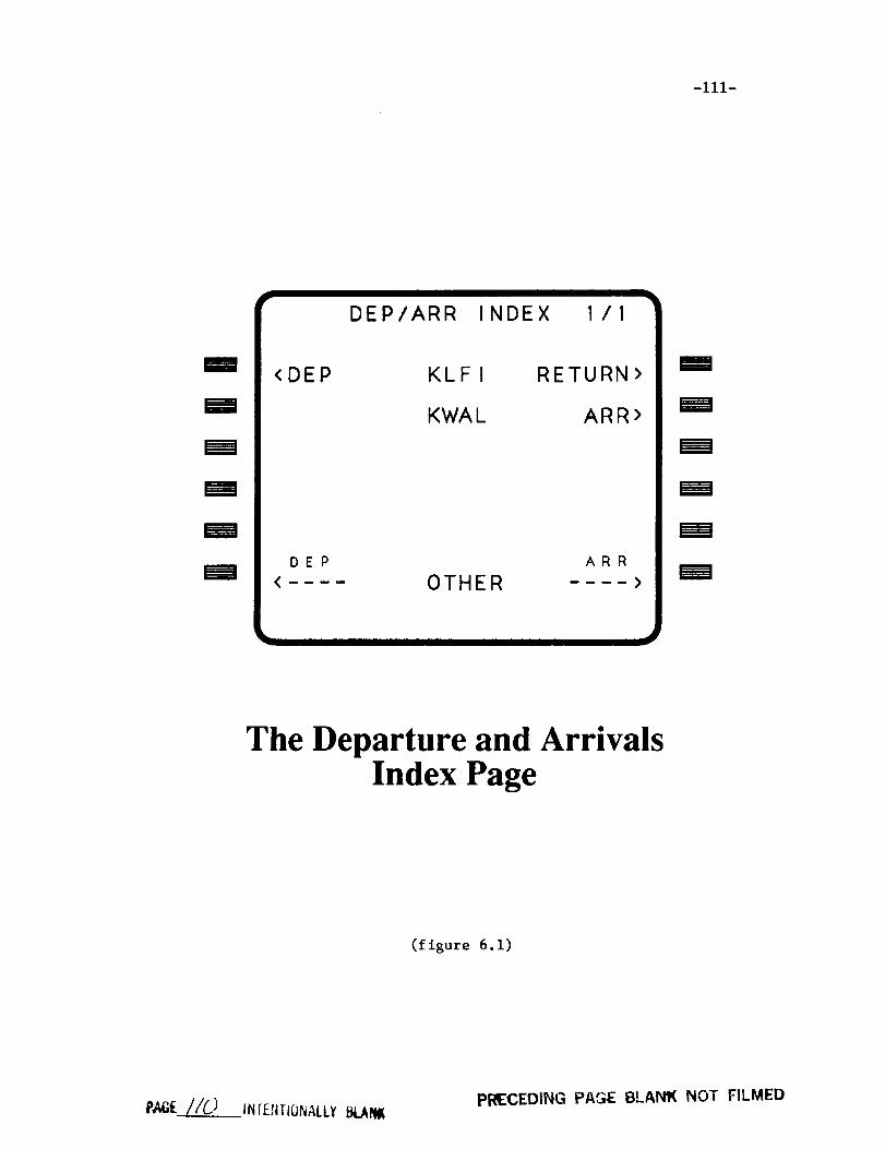
-iii-
m
m
u
m
D
u
<DEP
DEP/ARR INDEX I/I
KLFI RETURN>
KWAL ARR>
DEP ARR
< OTHER .... >
m
m
m
The Departure and ArrivalsIndex Page
(figure 6.1)
PA6E_//O INI-ENrlONALLY BLANIK PRECEDING PAGE 8LANIK NOT FILMED


-113-
KWAL
STARS
ML3SCL
WFSXX
<D/A INDEX
ARRIVALS 2/3
APPROACHES
GPSILSRUNWAY S
04
10
<SEL> 17
MORE
22
ROUTE>
B
The Arrivals Page
(figure 6.2)
P_ /[Oq" INTENTIONALLY BL,_N_ PR_ECEDIrq_G PAGE @LANK NOT FILMED

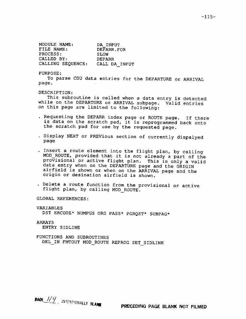
-115-
MODULE NAME:
FILE NAME:
PROCESS:
CALLED BY:
CALLING SEQUENCE:
DA INPUT
DEPARR.FOR
SLOW
DEPARR
CALL DA INPUT
PURPOSE:
To parse CDU data entries for the DEPARTURE or ARRIVAL
page.
DESCRIPTION:
This subroutine is called when a data entry is detected
while on the DEPARTURE or ARRIVAL subpage. Valid entries
on this page are limited to the following:
• Requesting the DEPARR index page or ROUTE page. If there
is data on the scratch pad, it is reprogrammed back onto
the scratch pad for use by the requested page.
• Display NEXT or PREVious section of currently dispalyed
page
• Insert a route element into the flight plan, by calling
MOD ROUTE, provided that it is not already a part of the
provisional or active flight plan. This is only a valid
data entry when on the DEPARTURE page and the ORIGIN
airfield is shown or when on the ARRIVAL page and the
origin or desination airfield is shown•
• Delete a route function from the provisional or active
flight plan, by calling MOD ROUTE•
GLOBAL REFERENCES:
VARIABLES
DST ERCODE* NUMPGS ORG PASS* PGRQST* SUBPAG*
ARRAYS
ENTRY SIDLINE
FUNCTIONS AND SUBROUTINES
DEL IN FMTOUT MOD ROUTE REPROG SET SIDLINE
PF_'CEDING PAGE BLANK NOT FILMED

-116-
MODULE NAME:
FILE NAME:
PROCESS:
CALLED BY:
CALLING SEQUENCE:
DEPARR
DEPARR.FOR
SLOW
CDUEXC
CALL DEPARR
PURPOSE:
To serve as the DEPARTURE/ARRIVAL page executive module.
DESCRIPTION:
This subroutine is the main procedure for the DEPARTURE/
ARRIVAL page software. It performs a few top-level functions
beginning with first pass initialization and the computation
of a few variables used by other modules. Input to the
DEPARTURE/ARRIVAL page is handled by one of two modules,
INDX_INPUT or DA_INPUT, depending upon which subpage of the
DEPARURE/ARRIVAL page is presently active. This procedure
also monitors the global variable PMODE so that in the event
the execute button is pressed, the subroutine SET SIDLINE is
called to update the <SEL> and <ACT> bugs on the D--EPARTURE
or ARRIVAL subpages. A call to the screen update procedure,
REFRESH_DA, is made every time the CDU executive calls DEPARR,
with one exception. When a new subpage has been requested,
the update of the CDU screen is delayed for one pass to allow
time for route function information to be updated.
GLOBAL REFERENCES:
VARIABLES
PAGE PASS* PGINIT* PLAN* PMODE SUBPAG* SUBPGINIT
ARRAYS
ENTRY*
FUNCTIONS AND SUBROUTINES
DA_INPUT INDX_INPUT PAGE_COUNT REFRESH DA SET SIDLINE

-117-
MODULENAME:FILE N_d_E:PROCESS:CALLED BY:CALLING SEQUENCE:
INDX INPUTDEPARR.FORSLOWDEPARRCALL INDX INPUT
PURPOSE:TO parse CDU data entries for the DEPARTURE/AP_IVAL
INDEX page.
DESCRIPTION:This subroutine is called when a data entry is detected
while on the DEPARTURE/AB/_IVALINDEX page. The followinglist describes the requests which are valid data entries.
• display DEPARTUREinformation for the ORIGIN airfield
. display ARRIVAL information for the ORIGIN airfield, foremergency return•
• display ARRIVAL information for the DESTINATION airfield.
• display DEPARTUREor ARRIVAL information for the specifiedairfield contained in AADCOM.
Upon receipt of a valid data entry, some initializationvariables are set, including the PAGE variable which is setto reflect the page number of the requested page.
GLOBAL REFERENCES:
VARIABLESADDR DST* ERCODE*ORG* PAGE* SUBPGINIT*
ARRAYSAIRPTS ENTRY
FUNCTIONS AND SUBROUTINESDEL IN LUARP

-118-
MODULENAME:FILE NAME:PROCESS:CALLED BY:CALLING SEQUENCE:
ITEM ADDRDEPARR.FORSLOWSET SIDLINEPATHADDR= ITEM ADDR (ITEM)
PURPOSE:To return the address in AADCOMof the first SID or
the last STAR or approach in the route buffer.
DESCRIPTION:This function searches the route buffer for the first
occurrance of a route function of type ITEM. The typesare identified by an integer value where, approach=5,SID=6, and STAR=7. Because the route buffer may containmore than one route function of a certain type, thefunction searches the buffer, from bottom to top, for thefirst SID or the last STAR or approach in the buffer. Ifsearching for a STAR or approach, the search halts whenthe item is located. If searching for a SID, then thesearch continues if a SID is found to ensure that it isthe first SID in the path.
GLOBAL REFERENCES:
ARRAYSRTE CNT
RECORDARRAYSRTE MOD
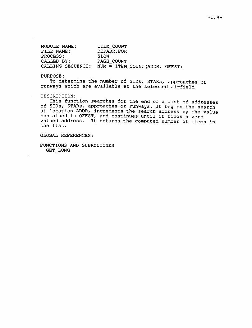
-119-
MODULENAME:FILE NAME:PROCESS:CALLED BY:CALLING SEQUENCE:
ITEM COUNTDEPARR.FORSLOWPAGECOUNTNUM = ITEM COUNT(ADDR, OFFST)
PURPOSE:TO determine the number of SIDs, STARs, approaches or
runways which are available at the selected airfield
DESCRIPTION:This function searches for the end of a list of addresses
of SIDs, STARs, approaches or runways. It begins the searchat location ADDR, increments the search address by the valuecontained in OFFST, and continues until it finds a zerovalued address. It returns the computed number of items inthe list.
GLOBAL REFERENCES:
FUNCTIONS AND SUBROUTINESGET LONG

-120-
MODULENAME:FILE NAME:PROCESS:CALLED BY:CALLING SEQUENCE:
MODIFYMODIFY.FORSLOWRT NEW, MODROUTECALL MODIFY(ADDRESS, TYPE, CLEAR_FLG)
PURPOSE:TO place airfield selection into the route buffer.
DESCRIPTION:This subroutine is called by the Departutes/Arrivals
page of the CDU to make modifications to the flight plan.Insertions and Deletions of SIDs, STARs, Approaches, andrunways may be requested. Note that insertions becomereplacements when the inserted type already exists.
Special processing occurs when the third parameter ofthe call list is set. This flag indicates the desire toreturn to the departure airfield after takeoff, usuallyfor emergency situations. A waypoint is created at thecurrent aircraft position. This waypoint is created as aI0 second update waypoint (see section 1.5.3.2). Theroute element selected on the DEP/ARR page is then placedin the route buffer with a call to WAYPOINTor GROUPandthe remainder of the flight plan is deleted.
If a selected type is a route function a search of theroute buffer is made to find an existing element of the typepassed in the parameter list. If found, the element isdeleted by a call to KILL and inserted by a call to GROUP.
If a match is not found the position of insertion isDetermined by the element type. An approach is alwaysplaced as the last element in the buffer. SIDs are firstunless a takeoff runway is present, in which case they areplaced after the two runway waypoints. STARs are placed atthe end unless a touchdown runway is defined. They areinserted two positions before the end to account for eithertwo runway waypoints or an approach with its entry waypoint.
Deletions of route functions are requested when the typeparameter is set to "DELETE". The actual type of the routefunction is not needed to remove it from the buffer sincethe passed address is used to locate the element.
Origin and destination runways have the types "RWYI" and"RWY2". The address parameter contains a pointer to thenavigation database when an insertion is requested. If theaddress value is zero a deletion is desired.
GLOBAL REFERENCES:
VARIABLESALTCOR ERCODE* GS LAT LON POSTIME* TIME

-121-
ARRAYSAIRPTS RTE CNT
RECORDARRAYSRTE MOD
FUNCTIONSAND SUBROUTINESDEL_RTE GROUPKILL MAKE WPT ORGRWYREMOVEWAYPOINT

-122-
MODULENAME:FILE NAME:PROCESS:CALLED BY:CALLING SEQUENCE:
MODROUTEDEPARR.FORSLOWDA INPUTCALL MODROUTE(ITEMNAME, ADDIT)
PURPOSE:To insert or delete route functions on the DEPARR
page.
DESCRIPTION:This subroutine searches for a route function, whose
name is given by the input parameter ITEMNAME, in BULKDATA with a call to LUSID. It then calls MODIFY with theaddress and type of the route function to be inserted ordeleted from the provisional or active route buffer. Theboolean input parameter ,ADDIT, specifies whether the itemis to be inserted or deleted. Finally, this routinecalls DEMODEwith a parameter of NOEXECto create the newwaypoint buffer and allow the pilot to execute the newpath.
Note the special case where a route function has beenselected on the ARRIVAL page and the ORIGIN airfield isshown. This indicates an emergency request to return tothe departure airfield, and some special processingoccurs. The origin airfield becomes the new destinationairfield and the origin and destination airfield flags,which affect the informational display and input parsingon the DEPARRpage, are updated appropriately.
GLOBAL REFERENCES:
VARIABLESADDR DST* ORG* PAGE PASS*
ARRAYSAIRPTS*
FUNCTIONS AND SUBROUTINESDEMODELURWYLUSID MODIFY SET SIDLINE

-123-
MODULENAME:FILE NAME:PROCESS:CALLED BY:CALLING SEQUENCE:
PAGE COUNTDEPARR.FORSLOWDEPARRCALL PAGE COUNT
PURPOSE:TO compute the number of subpages required to display
route function information for a selected airfield.
DESCRIPTION:If the DEPARTUREsubpage has been requested, this subroutine
compares the number of SIDs and runways available in BULKDATA for the selected airfield and chooses the larger of thetwo to determine the number of pages required for the DEPARTUREsubpage. If the ARRIVAL subpage has been requested, itcompares the number of STARs with the number of approaches andrunways and chooses the larger of the two to compute thenecessary number of subpages. One page is required to displayfive lines of route functions.
GLOBAL REFERENCES:
VARIABLESADDR NUMAPPNUMBOTHNUMPGS*NUMSSPAGE
FUNCTIONS AND SUBROUTINESGET LONG ITEM COUNT
m

-124-
MODULE NAME:
FILE NAME:
PROCESS:
CALLED BY:
CALLING SEQUENCE:
REFRESH DA
DEPARR.FOR
SLOW
DEPARR
CALL REFRESH DA
PURPOSE:
To update the CDU display for the DEPARURE/ARRIVAL pages.
DESCRIPTION:
This subroutine updates the CDU display for the DEPARTURE/
ARRIVAL INDEX page, the DEPARTURES subpage or the ARRIVALS
subpage with calls to FMTOUT. The entire screen is updated
every eight consecutive calls to this subroutine. The value
of PASS determines which particular lines are updated. During
the first call of the cycle, the appropriate page title is
output along with an indication of the current and last page
numbers.If the DEPARTURE/ARRIVAL INDEX page is currently active,
then the name of the ORIGIN airfield is shown on line #2
along with the labels for the LSKs which provide access to
the DEPARTURE and ARRIVAL subpages. If no ORIGIN airfield
exists in the current provisional flight plan, then blanks
are displayed in place of the airfield name. Likewise, the
name of the DESTINATION airfield is displayed on line #4 along
with the label for the LSK which provides access to the
ARRIVAL page. Again, if no DESTINATION airfield is present
in the current flight plan, then blanks are diplayed in
place of the name. Lines #Ii and #12 of the display contain
labels for the LSKs which provide access to the DEPARTURE and
ARRIVAL subpages for information on any airfield contained in
AADCOM.
If either the DEPARTURE or ARRIVAL subpage is currently
active then line #i will contain headings for the lists of SIDs,
STARs, approaches or runways available at the selected airfield.
Route element information is displayed on lines #2, #4, #6, #8,
and #i0. This route element information is contained in the
array, SIDLINE, which is updated by the subroutine, SET SIDLINE.Line #ii contains a dashed line, with the label "more" Tf additional
pages of information are available. Line #12 contains labels for
the LSKs which provide access to the INDEX and ROUTE pages.
GLOBAL REFERENCES:
VARIABLES
ADDR LBL NUMAPP NUMPGS PAGE PASS* SUBPAG
ARRAYS
AIRPTS DASHES SIDLINE
FUNCTIONS AND SUBROUTINES
FMTOUT

-125-
MODULENAME:FILE NAME:PROCESS:CALLED BY:CALLING SEQUENCE:
SET SIDLINEDEPARR.FORSLOWDEPARR, DA INPUT, MODROUTECALL SET SIDLINE
PURPOSE:To format lines of route element information for display
on the DEPARTUREor ARRIVAL page of the CDU.
DESCRIPTION:This subroutine is called to update the information in
the array SIDLINE, which contains appropriate route elementinformation for the selected airfield. This information isdisplayed by the subroutine REFRESHDA. Each element of thearray SIDLINE is a string of 24 characters and corresponds toa display line on the CDU. The information contained inSIDLINE is updated when either the DEPARTUREor ARRIVAL pageof the CDU is initially requested, and whenever the NEXT orPREVious subpages of the DEPARTUREor ARRIVAL page arerequested.
If the DEPARTUREpage is currently active, then the leftside of each line will contain the name of a SID and theright side of each line will contain a runway number,available in A_COM for the selected airfield. If theselected AIRFIELD is the ORIGIN airfield then <SEL> or <ACT>bugs will be displayed next to the route elements which arepart of the current provisional or active flight plans. Ifthe current clearance mode is ACT then <ACT> bugs will bedisplayed, otherwise <SEL> bugs will be displayed.
If the ARRIVAL page is currently active, the left side ofeach line will contain available STARs and the right sidewill contain the names of available approaches and runwaysfor the selected airfield. If the selected airfield is theDESTINATION airfield then <SEL> or <ACT> bugs will beappropriately displayed next to route elements which arepresent in the current provisional or active flight plans,again, dependent upon the current clearance mode.
Based on the value of SUBPAGE, this routine determines which
portion of the route element lists should be displayed, and
stores the appropriate names in the array SIDLINE. Also
it sets a flag which tells the subroutine REFRESH DA where
to display the header for the list of runways for a given
airfield. This is not a static position since the runway
header must follow the last approach for a selected airfield.
-126-
GLOBAL REFERENCES:
VARIABLESADDR DST NUMAPPNUMBOTHNUMSSORGPAGE PLAN* PMODERWYLABEL* SUBPAG
ARRAYSAIRPTS SIDLINE*
FUNCTIONS AND SUBROUTINESGET CHAR GET LONG ITEM ADDR

-127-
Section 6.3.2 THE DIRECT/INTERCEPT PAGE
This page is a variation of the LEGS page. The CDUdisplay is the same except for "Direct To" and "InterceptLeg" prompts on the bottom. Section 6.3.4 describes thestandard LEGS page and should be referenced to understandthe DIR/INTC page. This section describes the three modulesunique to the DIR/INTC page which are on the file INTC.FOR(Refer to figure 6.3 on the following page).
Two operations are performed on this page besides thestandard LEGS page functions. The first option creates awaypoint at the airplanes present position and connects itto the selected "To" waypoint. If the chosen waypoint ispart of the current flight plan the remaining waypointsalong the path are kept. The second option, like the first,requires a "To" waypoint entry. Once selected the CDUscreen is updated to prompt for an inbound bearing. A newwaypoint is generated 100 nautical miles away from theselected waypoint to define a leg with the desired inboundbearing. Remaining flight plan waypoints are kept forthis operation also.
Note that the pilot defined waypoint created at theaircraft position is updated every ten seconds to thecurrent aircraft position until the flight plan is madeactive.


-129-
D
m
m
M
m
m
ACT RTE LEGS 1/1
I 32" 1 NM
WFBBB 190/ 4000L TURN 6NM
WFBBC 1501 4000353" 2NM
WFBBD 150/ 4000353" 4NM
WFBBE 150/ 2723
-DIRECT TO ' NTC LEG-IIlII T0 IlugI
m
B
m
B
m
m
The Direct/Intercept Page
(figure 6.3)
P,,AO__.. ,'_v_m,_N,_r.tysamPRECEDING PAGE 6!.ANK NOT FILBI_)


-131-
MODULE NAME:
FILE NAME:
PROCESS:
CALLED BY:
CALLING SEQUENCE:
DIRECT
INTC.FOR
SLOW
LEGS
CALL DIRECT
PURPOSE:
To create a "Direct To" flight plan.
DESCRIPTION:
This subroutine is called when either a "Direct To" or
"Intercept Leg" entry is made on the DIR/INTC page of the
CDU. The selected waypoint's name is in the global CDU
entry buffer (ENTRY). Two valid situations may occur. If
the entered waypoint is found on the current flight plan,
all waypoints before the chosen one are removed from the
route buffer and the current aircraft position is inserted
as the "From" waypoint. When the waypoint is not entered
on the current flight plan a two waypoint path is generated
consisting of the current position and the selected waypoint.
A "Direct To" may not be performed to a holding pattern
waypoint. If attempted an error condition is flagged. The
function MAKE WPT is called to create the waypoint at the
aircraft position. The new waypoint is assigned the current
altitude and ground speed of the aircraft. The "From"
format of the standard legs page is requested once complete.
GLOBAL REFERENCES:
VARIABLES
ALTCOR ERCODE* FROMPG* GS LAT LON MODCNT PGRQST* PMODE
POSTIME* PTR2D TIME
ARRAYS
AIRPTS ENTRY RTE CNT*
RECORD ARRAYS
RTE MOD* WPT MOD
FUNCTIONS AND SUBROUTINES
BREAK MAKE WPT OPEN PAD NAME TRIM WPTS WPT ID
I_II_ _._0 INTF_;T_OlffAILTBIAl_ PRECEDII_G _AG_E __A_ NO7 F!LMED
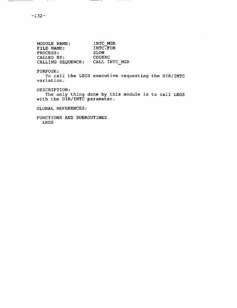
-132-
MODULENAME:FILE NAME:PROCESS:CALLED BY:CALLING SEQUENCE:
INTC MGRINTC.FORSLOWCDUEXCCALL INTC MGR
PURPOSE:To call the LEGS executive requesting the DIR/INTC
variation.
DESCRIPTION:The only thing done by this module is to call LEGS
with the DIR/INTC parameter.
GLOBAL REFERENCES:
FUNCTIONS AND SUBROUTINESLEGS
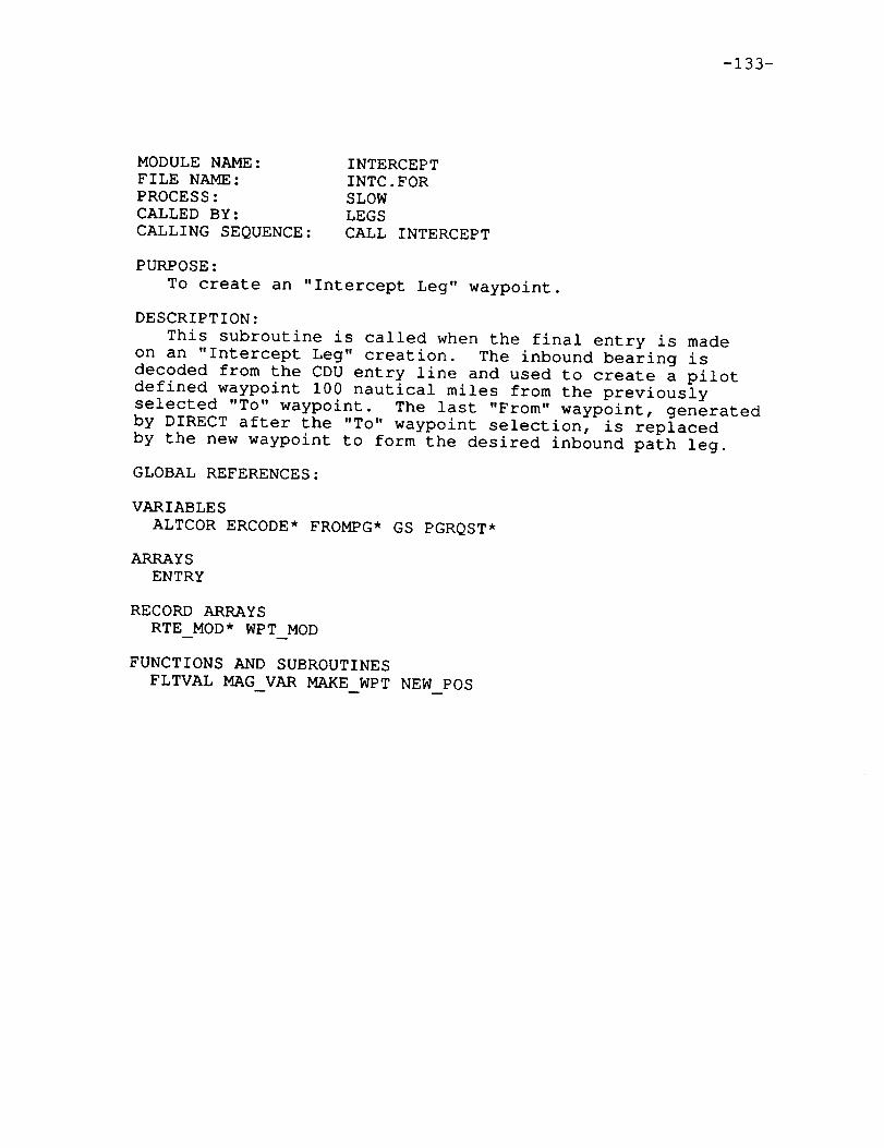
-133-
MODULENAME:FILE NAME:PROCESS:CALLED BY:CALLING SEQUENCE:
INTERCEPTINTC.FORSLOWLEGSCALL INTERCEPT
PURPOSE:To create an "Intercept Leg" waypoint.
DESCRIPTION:This subroutine is called when the final entry is made
on an "Intercept Leg" creation. The inbound bearing isdecoded from the CDU entry line and used to create a pilotdefined waypoint 100 nautical miles from the previouslyselected "To" waypoint. The last "From" waypoint, generatedby DIRECT after the "To" waypoint selection, is replacedby the new waypoint to form the desired inbound path leg.
GLOBAL REFERENCES:
VARIABLESALTCOR ERCODE* FROMPG*GS PGRQST*
ARRAYSENTRY
RECORDARRAYSRTE MOD* WPT MOD
FUNCTIONS AND SUBROUTINESFLTVAL MAGVAR MAKE WPT NEWPOS


-135-
Section 6.3.3 THE HOLD PAGE
The HOLD page is used by the flight crew to create aholding pattern at the present airplane position or at anywaypoint contained in the waypoint buffer (except DME turnwaypoints). When the HOLD key of the CDU is pressed, aspecial variation of the LEGS page format, the LEGS-HOLD
page, is displayed. If a holding fix is selected, a
variable HLD_WPT is assigned the name of the holding fix
and a holding pattern is set up with default parameters,
by calling HOLD INIT. The holding pattern is inserted into
the provisional--route buffer as well as the waypoint buffer
and the HOLD page format is displayed on the CDU. The HOLD
page allows the flight crew to modify the default
parameters of the holding pattern and execute the new
programmed route. Holding pattern parameters which may be
modified include the direction of turns in the holding
pattern, the holding speed and the bearing to the holding
fix. The flight crew may also specify the time required to
fly a straight leg of the holding pattern or the length of a
straight leg in nautical miles (Refer to figure 6.4 and6.5 on the following pages).
When a holding pattern is created, four points which
comprise the holding pattern are defined and inserted into
the provisional waypoint buffer. The names of the
waypoints which make up the holding pattern are HOLD1,
HOLD2, HOLD3 and HOLD4. These waypoints are inserted into
the path just prior to the position of the holding fix.The holding fix and the waypoint HOLD1 have the same
latitude, longitude and altitude (if one exists for the
fix) and are combined with the other hold waypoints toform a path section.
When the autopilot is engaged flying a holding pattern,the airplane repeatedly flys the holding pattern until a
request is made to exit. Each time the airplane passes
waypoint HOLD4, a check is made in HVGUID to see if a
request has been made to exit the holding pattern,
indicated by EXHOLD. If no request has been made to exit
the holding pattern, the active "to" waypoint pointer is
set back to point to HOLD1. Otherwise, the holding fix
becomes the active "to" waypoint.
It is possible to create a holding pattern in the
provisional flight plan which differs from the holding
pattern in the active flight plan. Additional bookkeepng
is performed to provide this capability.
_£_L____i!_ IEN [IONALLY BLANKPRE'_EOIN_ P_,':,,;F P!,.AN_ NOT F!LME'D


-137-
ACT RTE
1 32"
L TURN
WFBBC353"
WFBBD353"
WFBBE
__=_
Illlllllllll
LEGS
1NM
6NM
2NM
4NM
HOLD AT
1/1
190/ 4000
150/ 4000
150/ 4000
150/ 2723
PPOS>
m
/
The Legs Hold Page
(figure 6.4)
pRECEDING PA'_E I_LA,_K I'_QT FILMED


-139-
m
m
m
M
m
ACT RTE HOLD I/I
FIX
ILLARTURN DIR
RINBND
217LEG T IME
1 OM,NLEG DIST
3.5NM
CRS EX
TGT 5PD
210KTFIX ETA
1445:00IT TIME
<ERASE EXIT HOLD>
The Hold Page
(figure 6.5)
PRECEDING PAGE BLANK NOT FILMED


-141-
MODULE NAME:
FILE NAME:
PROCESS:
CALLED BY:
CALLING SEQUENCE:
GET ETA
HOLD.FOR
SLOW
HOLD_INPUT, REFRESH_HOLDETA = GET ETA
PURPOSE:
To compute the estimated time of arrival (ETA) at the
holding fix.
DESCRIPTION:
This routine computes the ETA at the selected holding
fix. It accumulates the distance to the holding fix by
adding the distance to the next waypoint, DTOGO, to the
distances along each of the legs of the path which lie
between the airplane and the holding fix. It divides
the accumulated sum by the current ground speed in feetper second and adds the result to the current time. The
ETA is computed and displayed only when the current
clearance mode is ACT, the airplane position is within
the holding pattern and ground speed is greater than zero.
GLOBAL REFERENCES:
VARIABLES
DTOGO GS HLD PTR PMODE TIME TOWPT
RECORD ARRAYS
WPT ACT
PA_ /._O .t_Er_TION,_LLy BLANIK
pRECEDING PAGE 8tANK NOT FILMED

-142-
MODULE NAME:
FILE NAME:
PROCESS:
CALLED BY:
CALLING SEQUENCE:
HOLD INIT
HOLD.FOR
SLOW
HLD IN
CALL HLD INIT (INDEX)
PURPOSE:
To create an initial holding pattern with default
parameters.
DESCRIPTION:
This routine is called from the LEGS-HOLD page when a
holding fix is selected. The input parameter is an index
into the waypoint buffer designating the position of the
holding fix. When this routine is called some flags are
initialized and a holding pattern is created with the
following defaults:
- holding pattern turns are right turns
- inbound course to fix is path bearing at fix waypoint
- hold speed is 210 kts
- if fix altitude is greater than 14000 feet, the
default leg time is 1.5 minutes, otherwise it is 1 minute
This routine calls the the LENGTHS routine to compute the
radius of the holding pattern turns, HLDRAD, and the lengths
of the straight legs of the holding pattern, LEG LEN. It
calls POINTS to compute the positions of the fou_ waypoints
which define the holding pattern and stores the necessaryvalues in HLDBUF.
GLOBAL REFERENCES:
VARIABLES
DELHOLD* EXHOLD* HLD WPT* MODCNT PGINIT*
RECORD ARRAYS
WPT MOD
FUNCTIONS AND SUBROUTINES
ANGL LENGTHS MTH$SIGN POINTS

-143-
MODULENAME:FILE NAME:PROCESS:CALLED BY:CALLING SEQUENCE:
HOLD INPUTHOLD?FORSLOWHLDWPTCALL HOLD INPUT(I)
PURPOSE:To parse CDU data entries for the main HOLD page.
DESCRIPTION:This subroutine is called when a data entry is detected
while on the HOLD page. Valid entries on this page arelimited to the following:
Deleting the holding pattern from the provisional oractive flight plan.
. Echoing the ETA into the scratch pad.
• Toggling the turn direction of the holding pattern.
• Requesting exit of holding pattern.
• Entering a new holding pattern speed, leg length orleg time.
• Cancelling the deletion of or exit from a holding pattern.
Note that once a holding pattern has been executed and flown,the holding pattern remains on the MAP display, even after ithas been exited• If the HOLDpage of the CDU is requested,the holding pattern information is displayed and the message"EXIT HOLD PATTERN ARMED" remains on line #12 of the CDU. Toenable removal of the holding pattern from the flight planand MAP display, after the holding pattern has been exited,special input processing has been implemented• The word"DELETE" may be entered using LSK-L6 or LSK-R6. This displaysthe ERASE label for LSK-L6 and therefore allows the holdingpattern to be erased. This required special processing in theflight plan modification code since "dead" waypoints cannotbe deleted under normal conditions•

-144-
GLOBAL REFERENCES:
VARIABLESDELHOLD* ERCODE* EXHOLD* HLD2D* LT_EXEC* PMODEPTR2DTIMED LEG
ARRAYSENTRY
RECORDARRAYSWPT MOD
FUNCTIONS AND SUBROUTINESANGL DEL IN DEMODEFLTVAL FMTOUTFMTTIM GET_ETA KILLLENGTHSMTH$SIGN POINTS
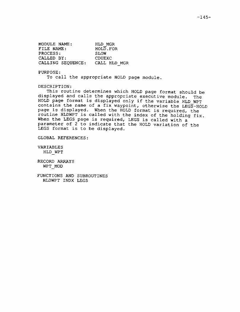
-145-
MODULENAME:FILE NAME:PROCESS:CALLED BY:CALLING SEQUENCE:
HLD MGRHOLD.FORSLOWCDUEXCCALL HLD MGR
PURPOSE:To call the appropriate HOLDpage module.
DESCRIPTION:This routine determines which HOLDpage format should be
displayed and calls the appropriate executive module. TheHOLD page format is displayed only if the variable HLD WPTcontains the name of a fix waypoint, otherwise the LEGS-HOLDpage is displayed. When the HOLD format is required, theroutine HLDWPTis called with the index of the holding fix.When the LEGS page is required, LEGS is called with aparameter of 2 to indicate that the HOLD variation of theLEGS format is to be displayed.
GLOBAL REFERENCES:
VARIABLESHLD WPT
RECORDARRAYSWPT MOD
FUNCTIONSAND SUBROUTINESHLDWPTINDX LEGS
-146-
MODULENAME:FILE NAME:PROCESS:CALLED BY:CALLING SEQUENCE:
HLDWPTHOLD.FORSLOWHLD MGRCALL HLD MGR(INDEX)
PURPOSE:
To serve as the HOLD page executive module
DESCRIPTION:
This subroutine is the main procedure for the HOLD page
software. It performs a few top-level functions includingfirst pass initialization. The input parameter is an index
into the waypoint buffer designating the position of the
holding fix. Input to the HOLD page is handled by the
module HOLD INPUT. A call to the screen update module,
REFRESHHOLD, is made every time the HOLD page executivemodule, HLDWPT, is called.
GLOBAL REFERENCES:
VARIABLES
PASS* PGINIT*
ARRAYS
ENTRY*
FUNCTIONS AND SUBROUTINES
HOLD INPUT REFRESH HOLD

-147-
MODULENAME:FILE NAME:PROCESS:CALLED BY:CALLING SEQUENCE:
INDXHOLD.FORSLOWHLD_MGR, LENGTHSI = INDX(NAME)
PURPOSE:To locate the holding fix in the waypoint buffer.
DESCRIPTION:This function is called with the five character name
of the holding fix waypoint. The waypoint buffer issearched and the index into the structure is returned.A zero index is returned when the fix waypoint is notfound in the waypoint buffer.
GLOBAL REFERENCES:
VARIABLESMODCNT
RECORDARRAYSWPT MOD
-148-
MODULENAME:FILE NAME:PROCESS:CALLED BY:CALLING SEQUENCE:
LENGTHSHOLD.FORSLOWHOLD_INIT, HOLD_INPUTCALL LENGTHS(TIME, SPD, LEN, RAD)
PURPOSE:To compute the radius of the turns and the lengths of
the straight legs of the holding pattern.
DESCRIPTION:This routine is called on creation of a holding pattern
or when leg time or holding speed are modified by crewinputs to the CDU HOLD page. The input parameters are thedesired time, in minutes, to fly one straight leg of theholding pattern and the requested speed in knots. Thelength for the straight legs of the holding pattern as wellas a new turn radius for the holding pattern are computedusing the following equations:
length = speed in feet per second * time in seconds2
radius = (true airspeed + wind speed) /
(gravitational acceleration * tan (nominal bank angle))
GLOBAL REFERENCES:
VARIABLES
HLD WPT
RECORD ARRAYS
WPT MOD
FUNCTIONS AND SUBROUTINES
INDX

-149-
MODULENAME:FILE NAME:PROCESS:CALLED BY:CALLING SEQUENCE:
POINTSHOLD.FORSLOWHOLD INIT, HOLD INPUT
u
CALL POINTS(I, RAD, LEGLEN, INCRS, SPD)
PURPOSE:
TO create the four waypoints which define a holding
pattern.
DESCRIPTION:
This routine computes the positions of the four waypoints
which define a holding pattern at the selected holding fix.
The input parameters are as follows:
I - an index into the waypoint buffer designating the
position of the holding fix
RAD - the holding pattern turn radius in feet
LEGLEN - the length in feet of one of the holding pattern
straight legs
INCRS - the bearing of the path segment preceeding the
holding fix
SPD - the desired speed for the holding pattern (knots)
For each waypoint, the latitude and longitude are computed
with a call to PROJPOINT. Along with latitude and longitude,
the altitude, speed, turn radius, and associated navaid must
be stored in HLDBUF for use by the path definition modules.
The speed and turn radius are determined by the values of the
input parameters RAD and SPD. The associated navaid is the
the same as that of the holding fix. If the altitude flag in
the waypoint buffer is set for the holding fix, then the
altitude of the hold waypoints are set equal to the altitude
of the holding fix, otherwise the default altitude of 15,000
feet is used. Also, note that the holding pattern turns are
defined as DME turns. The latitude and longitude define the
turn center, and therefore the bearing from the turn center to
the inbound waypoint must be stored, and the altitude must be
negated to indicate that they are inbound waypoints. For the
outbound waypoints, the turn angle must be stored. (see
AADCOM format description for SID/STAR Route functions)
GLOBAL REFERENCES:
RECORD ARRAYS
HLDPTN* HLDPTS* WPT MOD
FUNCTIONS AND SUBROUTINES
ANGL LOCAL ERAD MTH$SIGN PROJPOINT SCOSD

-150-
MODULENAME:FILE NAME:PROCESS:CALLED BY:CALLING SEQUENCE:
PROJPOINTHOLD.FORSLOWPOINTSCALL PROJPOINT(PTI, BRG, DIST, PT2)
PURPOSE:To compute a waypoint latitude and longitude.
DESCRIPTION:This routine computes the latitude and longitude of a
waypoint given a reference waypoint and a bearing anddistance from that point. It uses LATFT and LONFT whichare created by LOCAL ERAD. The PTS structure is used sothat the computed latitudes and longitudes can be storeddirectly into HLDBUF.
GLOBAL REFERENCES:
VARIABLESLATFT LONFT
FUNCTIONS AND SUBROUTINESSCOSD

-151-
MODULE NAME:
FILE NAME:
PROCESS:
CALLED BY:
CALLING SEQUENCE:
REFRESH HOLD
HOLD.FOR
SLOW
HLDWPT
CALL REFRESH HOLD(I)
PURPOSE:
To update the CDU display for the HOLD page.
DESCRIPTION:
This subroutine updates the CDU display for the HOLD page
with calls to FMTOUT. The entire screen is updated every
fourteen consecutive calls to this subroutine. The value of
PASS determines which particular lines are updated. During
the first call of the cycle, the page title is output along
with an indication of the current and last page numbers.
Information about the holding pattern is displayed on lines#i through #I0. This information includes:
. the name of the holding fix
the direction of holding pattern turns
the target speed for the holding pattern
• the holding pattern leg time and leg distance
the bearing of the leg which aproaches the holding fix
• the estimated time of arrival at the holding fix
• the desired holding pattern exit time
The LSK labels which are displayed on line #12 depend uponcurrent clearance mode. If the current clearance mode is
original or MOD then an ERASE label is displayed on the left
side of this line, if the current clearance mode is ACT then
initially the ERASE label is displayed on the left and EXIT
HOLD is displayed on the right side of this line. If the
LSK labelled EXIT HOLD has been pressed then the message,
"EXIT HOLD PATTERN ARMED", will be displayed on line #12,
and if the LSK labelled ERASE has been pressed when the
current clearance mode is ACT then the message, "DELETE
HOLDING PATTERN" will be displayed on line #12.
GLOBAL REFERENCES:
VARIABLES
DELHOLD EXHOLD HLD WPT PASS* PMODE
RECORD ARRAYS
WPT MOD
FUNCTIONS AND SUBROUTINES
ANGL FMTOUT FMTTIM FSTRNG GET ETA MTH$SIGN TITLE

-153-
Section 6.3.4 THE LEGS PAGE
The LEGS page of the CDU allows the entry, manipu-lation, and application of constraints to flight planwaypoints. Four separate CDU pages actually use theLEGS page format. The various pages are listed belowalong with CDU access information.
LEGS - The standard legs page which is accessed byusing the LEGS key or selecting the "<LEGS" option onthe ROUTE INDEX page.
DIRECT/INTERCEPT - This page uses the LEGS format exceptfor the addition of the box prompts displayed on thebottom which allow the entry of the destination waypoint.Once the waypoint is selected this page automaticallytransfers to the standard legs page. The DIR/INTC keyis the only access to this page.
HOLD - This page uses the LEGS format only until the holdwaypoint is selected, at which time the hold page usesits unique page format. The only deviation from thestandard legs page is the box prompts provided forhold waypoint entry.
FROMWAYPOINT - This page is accessed by selecting the"<FROM WPT" prompt on the ROUTE INDEX page. This pagediffers from the standard legs page in that only thefirst waypoint shown. The active LEGS page starts withthe "To" waypoint while the FROMpage uses the "From"waypoint. The modified (MOD) LEGS page starts withthe second flight plan waypoint while the FROMpageuses the first. Both pages are identical in theinitial clearance mode (start with #i).
Note that any LEGS page operations may be performed whileon the other variations of the LEGS page. Refer to figure
6.6 for a picture of the standard LEGS page.
Individual waypoints may be entered and deleted on the
LEGS page. The altitude, ground speed, and turn radius
constraints associated with the waypoint may also be
entered. As many "sub-pages" as necessary are maintained
to cover the entire flight plan. The current and last
page numbers are shown on the LEGS title line. For a
detailed functional description of the LEGS page refer
to the CDU requirements produced by Charlie Knox of NASA.
The remaining pages of the section explain the 25 modules
associated with the LEGS page. Other sections of this
document must be referenced for information about the
variations of the standard LEGS page.
IPAQE.___q_ _NLr_,T_ONAI_lyBLA/_ PRIZCEDING PAGE BLANK NOT FILMED


-155-
i
m
m
E
i
ACT RTE
1 32"
WFBBBL TURN
WFBBC353"
WFBBD353 °
WFBBE
LEGS
1NM
6NM
2NM
4NM
190/
150/
150/
150/
<INDEX
1/1
4OOO
4000
4000
2723
The Legs Page
(figure 6.6)
P_ INT_-NTIONALLY BLANK ....._ .i ._i_._: _,q,T r.'t',_j_,r_


-157-
MODULE NAME:
FILE NAME:
PROCESS:
CALLED BY:
CALLING SEQUENCE:
ADD WPT
LEGS.FOR
SLOW
HLD POS, WPT DATA
CALL ADD WPT(INDEX)
PURPOSE:
To insert a waypoint into the flight plan.
DESCRIPTION:
This procedure adds a waypoint to the flight plan by
creating a waypoint in the route buffer. Three cases must
be accounted for. The waypoint may be appended to the end
of the route buffer, inserted at a route dicontinuity, or
inserted between flight plan waypoints. When inserted
between waypoints that are part of a route function, the
route function must be split into separate parts. This
procedure is also used to update the active "To" waypoint.
When a waypoint which appears further along in the flight
plan is entered at the current "To" waypoint, which is
highlighted in reverse video, the flight plan updated to
reflect the new destination waypoint. All waypoints behind
the new "From" waypoint are removed from the flight plan,
which must be manually activated to become the new active
flight plan.
The subroutine WAYPOINT is called to actually perform
the waypoint insertion. Checks are made prior to calling
WAYPOINT to identify the situations mentioned above. When
the waypoint is inserted within an existing route function
the procedure SPLIT is called to break the route function
at the selected waypoint. The insertion is then made
between the two new route function pieces.
GLOBAL REFERENCES:
VARIABLES
ACTCNT ERCODE* MODCNT PMODE TOWPT
ARRAYS
AIRPTS ENTRY RTE CNT
RECORD ARRAYS
RTE MOD WPT ACT WPT MOD
FUNCTIONS AND SUBROUTINES
BOUNDS PAD NAME RTE WPT SPLIT TRIM WPTS WAYPOINT WPT ADDR
WPT ID

-158-
MODULENAME:FILE NAME:PROCESS:CALLED BY:CALLING SEQUENCE:
ALTXLEGS.FORSLOWFLT_TYPE_INP, LINK_EA, NMBRS, PFINPALT = ALTX(TEXT, COUNT)
PURPOSE:
To decode altitude entries.
DESCRIPTION:
This function evaluates an ASCII numeric string which
represents an altitude. Note that values entered with
three or less digits are assumed to be flight levels. Anyvalue greater than 18,000 feet must not have non-zero tens
or ones digits since it will be displayed as a flight level.
The CDU error code value may be set to reflect an "OUT OF
RANGE" or "BAD FORMAT" error. Out of range errors ocuur
when the value is not between 0 and 40,000 feet.
GLOBAL REFERENCES:
VARIABLES
ERCODE
FUNCTIONS AND SUBROUTINES
FLTVAL

-159-
MODULENAME:FILE NAME:PROCESS:CALLED BY:
CALLING SEQUENCE:
BOUNDSLEGS.FORSLOWADD PLAN, ADD WPT, HLD IN, KILL WPT,LINK_PD, MERGE, NEXT_WPT, TRIM WPTS, RTECALL BOUNDS(INDEX, IN_OFS,OUT__0FS,STEP)
PURPOSE:
To find entry/exit waypoint offsets.
DESCRIPTION:
This subroutine is called to compute the byte offsets, from
the start of a route function defined in the route buffer, of
the entry and exit waypoint pointers (see section 1.5.1.1 for
database formats). When one of the waypoints is not defined
a zero is returned as its offset. The number of bytes between
consecutive waypoints in the route function is also returned.
Note that the STEP may be a negative value since airways may
be flown in either direction.
The parameter list for BOUNDS consists of one input and
three output values. The first is the index into the route
buffer of the chosen route function. The output parameters
are the entry waypoint offset, exit waypoint offset, and
waypoint separation respectively.
GLOBAL REFERENCES:
RECORD ARRAYS
RTE MOD
FUNCTIONS AND SUBROUTINES
ENTRY WPT

-160-
MODULENAME:FILE NAME:PROCESS:CALLED BY:CALLING SEQUENCE:
DSP WPTSLEGS.FORSLOWLEGSCALL DSP WPTS(PAGE ID)
m
PURPOSE:
To create CDU display data for the LEGS page.
DESCRIPTION:
This subroutine is called to update the CDU display
screen with the information pertinent to the "LEGS" page
of the CDU. The entire screen is updated every six
consecutive calls to this procedure. During the first call
of the cycle the title line and fixed labels are generated.
On subsequent calls the waypoint information for one of the
five available slots on the screen is updated.
Waypoint information is shown on CDU line pairs starting
with #2/#3 and ending with #10/#11. Three different things
can occupy a line pair. The lines are blanked when finished
with waypoint buffer elements. A route discontinuity marker
is shown for positions which correspond to a break in the
flight plan. Lines that show waypoint data have the way-
point name, speed, altitude, inbound bearing, and inbound
leg distance. Other information appears with the waypoint
data at certain times. The "<CTR>" bug is shown on the
map center waypoint during Plan mode. The waypoint radius
override symbol "R" is placed on waypoints which have a
manually entered turn radius. The waypoints which were
assigned a zero turn radius because of bad flight plan
geometery are indicated by the "*" symbol. When the
displayed waypoint is the "To" waypoint of the active
flight plan the name is shown in reverse video and the
inbound distance is from the airplane, not the previous
waypoint.
Note that the altitude and speed fields may be dashed
when their respective constraints are undefined. When
shown, the values may be either small or large font
depending on the constraint type. The description for
the module XLAT RTE discusses constraint types.
-161-
GLOBAL REFERENCES:
VARIABLESCTR DTOGOFIRST PTR LASTPG MODCNTPAGE PASS* PLANMPMODETOWPT
ARRAYSBOXES
RECORDARRAYSWPT MOD
FUNCTIONS AND SUBROUTINESFMTOUTFSTRNGHLD END INBOUNDINTC_END LEG END STEPS TITLE

-162-
MODULENAME:FILE NAME:PROCESS:CALLED BY:CALLING SEQUENCE:
HLD ENDLEGS.FORSLOWDSP WPTSCALL HLD END
PURPOSE:To create CDU display labels for the LEGS page.
DESCRIPTION:This procedure updates CDU display lines #Ii and #12
for the HOLD variation of the LEGS page. The "HOLD AT"query is placed on line #ii. Line #12 contains thebox prompts and "PPOS>" response which may be selectedusing either LSK-L6 or LSK-R6.
GLOBAL REFERENCES:
ARRAYSBOXES
FUNCTIONS AND SUBROUTINESFMTOUT

-163-
MODULENAME:FILE NAME:PROCESS:CALLED BY:CALLING SEQUENCE:
HLD INLEGS.FORSLOWHLD POS, WPT DATACALL HLD IN(WPT INDEX)
PURPOSE:To initiate the processing of a selected hold waypoint.
DESCRIPTION:This procedure is called when a holding pattern is
requested on the LEGS-HOLDpage. The input parameter is anindex into the waypoint buffer designating the selected way-point. If the parameter is zero the waypoint buffer issearched for the name stored on the global CDU entry line,ENTRY. The procedure HOLD INIT is called to create theholding pattern waypoints Tn HLDBUF. If the hold waypointis part of a route function the route function waypointsare separated into two pieces by calling the procedureSPLIT. The holding pattern, which consists of an entrywaypoint and a hold route function, is inserted before thehold waypoint in the route buffer. The last step is toautomatically signal the CDU executive to perform a pagechange to the hold page display.
GLOBAL REFERENCES:
VARIABLESERCODE* HLD WPT* MODCNTPGRQST* START
RECORDARRAYSRTE MOD* WPT MOD
FUNCTIONSAND SUBROUTINESBOUNDSHOLD INIT OPEN PAD NAMERTE WPT SPLIT WPT ADDR

-164-
MODULENAME:FILE NAME:PROCESS:CALLED BY:CALLING SEQUENCE:
HLD POSLEGS.FORSLOWLEGSCALL HLD POS
PURPOSE:To create a holding pattern at present position.
DESCRIPTION:This subroutine inserts a holding pattern about the
airplane's present position on the flight plan. A "PPOS"entry is simulated to create the "hold waypoint" in theroute buffer by calling ADD WPT. The route discontinuitygenerated from the call is removed and aircraft altitudeand ground speed are set up as constraints. A new waypointbuffer is created by calling XLAT RTE which is used whenHLD IN is called to create the holding pattern at the newPPOS waypoint.
GLOBAL REFERENCES:
VARIABLESALTCOR ERCODE* GS PMODESTRING* TOWPT
ARRAYSCONBUF* ENTRY*
RECORDARRAYSRTE MOD* WPT MOD
FUNCTIONS AND SUBROUTINESADD WPT DEMODEFIND EMPTYHLD IN KILL XLAT RTE

-165-
MODULENAME:FILE NAME:PROCESS:CALLED BY:CALLING SEQUENCE:
INBOUNDLEGS.FORSLOWDSP WPTSCALL INBOUND(WPT INDEX, BRG TEXT)
PURPOSE:
To generate bearing text for LEGS display.
DESCRIPTION:
This subroutine creates ASCII text for display in the
inbound bearing field of the LEGS page. The created
character string will have "TURN" for outbound DMA way-
points. Other type will have a number, up to three digits,
with a degree symbol. Note that the bearing saved in the
waypoint buffer for DMA inbound waypoints is perpendicular
to the actual inbound bearing.
GLOBAL REFERENCES:
RECORD ARRAYS
WPT M0D
FUNCTIONS AND SUBROUTINES
ANGL FSTRNG MTH$SIGN

-166-
MODULENAME:FILE NAME:PROCESS:CALLED BY:CALLING SEQUENCE:
INTC ENDLEGS.FORSLOWDSP WPTSCALL INTC END
PURPOSE:To create CDU display labels for the LEGS page.
DESCRIPTION:This procedure updates lines #ii and #12 of the CDU
display screen when the DIR/INTC version of the LEGSpage is shown. Two distinct formats are used for thispage depending on the status of the global flag INTCF.This happens because the DIR/INTC page requires a userresponse after the initial DIR/INTC selection. Thenormal display shows the "direct to" and "intercept leg"prompts. When the intercept leg choice is selectedthe lines are updated with the intercept course prompt.
GLOBAL REFERENCES:
VARIABLES
INTCF
ARRAYS
BOXES DASHES
FUNCTIONS AND SUBROUTINES
FMTOUT

-167-
MODULENAME:FILE NAME:PROCESS:CALLED BY:CALLING SEQUENCE:
KILL WPTLEGS?FORSLOWWPTDATACALL KILL WPT(WPTINDEX)
PURPOSE:To remove a waypoint from the flight plan.
DESCRIPTION:This subroutine removes a waypoint from the flight plan
by modifying the route buffer. When the waypoint is notpart of a route function it is simply replaced by a routediscontinuity marker. Otherwise the route function whichcontains the waypoint must be split into two pieces thatcontain the preceeding and following waypoints.
In the case of the route buffer element being a singlewaypoint a test is made on the following route bufferelement. If it is a route function the deleted waypoint wasits entry waypoint. The module NEXT WPT is called to makethe next route function waypoint in sequence the new entrywaypoint. The same tests are made when the exit waypoint of
a route function is deleted. The waypoint may have also
served as the entry waypoint of a following route function
in which case the NEXT WPT call is required. When the exit
waypoint is deleted the previous waypoint on the flight plan
is used as the new exit, unless it has an undefined entry
waypoint. A route function with an undefined entry gene-
rates a single waypoint in the waypoint buffer (the exit),
so the exit deletion creates a null route function (undefined
entry and exit). If the route function has been reduced to a
one waypoint route function, having the same entry and exit
points, the route function is deleted and the entry waypoint
remains followed by a route discontinuity. All other cases
of removing a route function waypoint are handled by the
procedure SPLIT.
GLOBAL REFERENCES:
VARIABLES
ERCODE* MODCNT
ARRAYS
RTE CNT
RECORD ARRAYS
RTE MOD* WPT MOD
FUNCTIONS AND SUBROUTINES
BOUNDS BREAK NEXT WPT OPEN RTE WPT SPLIT WPT ADDR

-168-
MODULENAME:FILE NAME:PROCESS:CALLED BY:CALLING SEQUENCE:
LEGSLEGS.FORSLOWHLD MGR, INTC MGR, LEG MGRCALL LEGS(PAGE ID)
PURPOSE:To serve as the LEGS page executive module.
DESCRIPTION:This procedure is called from the various LEGS format
managers to handle function and data entries, and generatethe data for the CDU LEGS page display. The one inputparameter identifies the calling manager module, which isused to select the minor variations in the LEGS page format.
The first time the LEGS page is called after a changefrom another page format, some initialization is performed.The LEGS subpage is set to one unless returning from theLEGS-TIME page. In that case the subpage remains the sameas it was on the LEGS-TIME page. Other LEGS variables areset to their default values.
A number of independent operations are performed in the
body of the procedure. The following is a sequential list
describing the functions.
If the CDU clearance mode has changed to active, change
from "FROM" format to standard.
Call SET PG to set up LEGS page parameters.
Determine if the Plan Mode LEGS format is to be used. In
this mode the navigation display format is centered at
the waypoint marked with the "<CTR>" bug on the CDU. This
format of the LEGS page is only shown when the NAY display
is in Plan mode and the standard LEGS page is being used.
Note that on the first pass of Plan mode the "<CTR>" bug
is set to the last selected map center waypoint (see the
module description for CDUFST).
Respond to the following function entries.
Advance/Backup to next subpage.
Advance/Backup "<CTR>" bug (Plan mode only).
Calls NEWCTR.
. Change to ROUTE INDEX page (Standard LEGS only).
Hold at PPOS (HOLD page only). Calls HLD_POS.
Reject modified flight plan (standard LEGS only).
Echo waypoint name to scratch pad. Calls WPNAME.
Echo ALT/SPD constraints to scratch pad. Calls
PROG NUM.
Respond to data entries by calling WPT_DATA.
Update display lines by calling DSP_WPTS.

-169-
GLOBAL REFERENCES:
VARIABLESCTR* DISPST ERCODE*FROMPG*INTCF* LASTPG LATCEN LONCENMODCNTPAGE* PASS* PGINIT* PGRQST* PLANMPMODE
ARRAYSENTRY* OLDPAGE
RECORDARRAYSWPT MOD
FUNCTIONSAND SUBROUTINESDSP WPTSHLD POS NEWCTRPROGNUMREJECT SET PG WPNAMEWPT DATA

-170-
MODULENAME:FILE NAME:PROCESS:CALLED BY:CALLING SEQUENCE:
LEG ENDLEGS.FORSLOWDSP WPTSCALL LEG END
PURPOSE:To create CDU display labels for the LEGS page.
DESCRIPTION:This subroutine is called to update lines #ii and #12
of the CDU display screen when in the standard LEGS format.The reference time of arrival and RTA waypoint name areshown in the middle of lines #Ii and #12 when defined. Theprompts "<INDEX" and "ERASE>" are placed on the outside ofline #12 to identify the use of LSK-L6 and LSK-R6. Theerase prompt is only shown during the MODCDU clearancemode.
GLOBAL REFERENCES:
VARIABLESPMODERTA INDX RTA TM
RECORDARRAYSWPT MOD
FUNCTIONS AND SUBROUTINESFMTOUTFMTTIM
-171-
MODULENAME:FILE NAME:PROCESS:CALLED BY:CALLING SEQUENCE:
LEG MGRLEGS.FORSLOWCDUEXCCALL LEG MGR
PURPOSE:To call the LEGS page module with standard format.
DESCRIPTION:Since the standard legs format is used by several pages
the main LEGS procedure must be called with a parameterindicating specific format. When the executive wishes toactivate the standard legs format it calls the procedureLEG MGRwhich in turn calls LEGS with a parameter valueof _I"
GLOBAL REFERENCES:
FUNCTIONSAND SUBROUTINESLEGS

-172-
MODULENAME:FILE NAME:PROCESS:CALLED BY:CALLING SEQUENCE:
NEWCTRLEGS.FORSLOWLEGSCALL NEWCTR(STEP)
PURPOSE:To move the "<CTR>" bug on the LEGS page.
DESCRIPTION:The "<CTR>" bug is moved STEP increments on the display.
Note that STEP may be negative to "step back" or zero toforce the page computation mentioned below. The bug will
wrap around the ends of the flight plan. Also another
STEP is performed when the new placement is on a route
discontinuity. The navigation display format map center
variables are set to the position of the new "<CTR>" way-
point. The last action is the computation of the CDU
LEGS page which contains the "<CTR>" waypoint. This is
performed because the bug may be STEPed off the current
page.
GLOBAL REFERENCES:
VARIABLES
CTR FIRST PTR GDTIME* LATCEN* LONCEN* MODCNT PAGE*
RECORD ARRAYS
WPT MOD
-173-
MODULENAME:FILE NAME:PROCESS:CALLED BY:CALLING SEQUENCE:
PURPOSE:
NEWENTRYLEGS.FORSLOWNEXT_WPT, SPLIT, TRIM WPTSCALL NEW_ENTRY(RTE_PTR,WPTADR,
RTE_OFF, EXIT OFF)
TO define a new route function entry waypoint.
DESCRIPTION:This module sets up a new route function entry waypoint.
The route buffer index for the new entry waypoint is passedas RTE PTR. The waypoint's database address and routeoffset--are also provided from the parameter list. Thelast paramter in the list is the offset of the exit way-point.
A check is made to determine if the new route entrywaypoint is the same as the route exit waypoint. If so,the route function is removed to leave the entry waypointonly. Any waypoint constraints (ALT/SPD/RAD) are extractedfrom the constraint buffer and assigned to the new waypoint.
GLOBAL REFERENCES:
RECORDARRAYSRTE MOD*
FUNCTIONS AND SUBROUTINESKILL TYPE WPT XFER CON
-174-
MODULENAME:FILE NAME:PROCESS:CALLED BY:CALLING SEQUENCE:
NEXT WPTLEGS.FORSLOWKILL WPTCALL NEXT WPT(INDEX)
PURPOSE:To modify a route function when its entry waypoint is
deleted.
DESCRIPTION:When the entry waypoint of a route function is deleted
a route discontinuity is inserted before the route functionand a new entry waypoint is selected. The new entry isset up by a call to NEWENTRY.
When the route functTon does not have an exit waypointdefined, its definition only creates one waypoint, the entry,in the waypoint buffer. When the entry waypoint is deletedthe route function is null, having neither an entry nor anexit waypoint.
GLOBAL REFERENCES:
RECORDARRAYSRTE MOD
FUNCTIONS AND SUBROUTINESBOUNDSBREAK GET LONG KILL NEWENTRY OPEN

-175-
MODULENAME:FILE NAME:PROCESS:CALLED BY:CALLING SEQUENCE:
NMBRSLEGS.FORSLOWLEGSCALL NMBRS(WPT INDEX)
PURPOSE:To decode constraint data entries for the CDU LEGS page.
DESCRIPTION:This module is called to decode the numeric constraint
value input for the waypoint indicated by the inputparameter WPT INDEX.
The data may be either speed, altitude, or turn radiusinformation. Speed and altitude values may be entered onany display line containing a waypoint name. Turn radiusvalues may only be assigned to waypoints not used in DMAturns. The five valid entry formats are shown below. The"nnn" depicts a one or more character numeric string.
nnn/nnn
nnn
nnn//nnn
R/nnn
Speed/Altitude entry
Altitude entry
Speed entry
Altitude entry
Turn radius entry
To delete the manually assigned speed and altitude entries
at a waypoint use the LSKs to direct the DELETE text
from the scratch pad to the chosen waypoint. Entering "R/"
at a particular waypoint removes a manually entered turnradius.
Note that constraints may not be assigned to holding
pattern waypoints.
GLOBAL REFERENCES:
VARIABLES
ERCODE* INDAT MODCNT
ARRAYS
ENTRY
RECORD ARRAYS
WPT MOD
FUNCTIONS AND SUBROUTINES
ALTX DEL IN FLTVAL KILL CON LIB$MATCHC NEW CON

-176-
MODULENAME:FILE NAME:PROCESS:CALLED BY:CALLING SEQUENCE:
PAD NAMELEGS.FORSLOWADD WPT, DIRECT, HLD INNAME= PAD NAME()
PURPOSE:To append blanks to the entered waypoint name.
DESCRIPTION:PAD NAME returns a five character ASCII string which is
set to the name in the CDU entry line padded with blankson the end. If the initial data is longer than fivecharacters the returned string is "?????".
GLOBAL REFERENCES:
VARIABLESECHARS
ARRAYSENTRY

-177-
MODULENAME:FILE NAME:PROCESS:CALLED BY:CALLING SEQUENCE:
PROGNUMLEGS.FORSLOWLEGSCALL PROGNUM
PURPOSE:TO echo altitude and speed values to the CDU scratch pad.
DESCRIPTION:This procedure is called when the LSK adjacent to a way-
point's altitude and speed values is pressed. The valuesare echoed to the scratch pad as if manually entered, whichallows their use elsewhere. PROGNUM calls FMTOUTtoperform the actual scratch pad update after the ASCII datais encoded from the waypoint buffer.
GLOBAL REFERENCES:
VARIABLESERCODE*FIRST PTR MODCNTPAGE
ARRAYSENTRY
RECORDARRAYSWPT MOD
FUNCTIONS AND SUBROUTINESFMTOUT ISTRNG

-178-
MODULENAME:FILE NAME:PROCESS:CALLED BY:CALLING SEQUENCE:
SET PGLEGS.FORSLOWLEGS, LEG TIMECALL SET PG(FROMFLAG)
PURPOSE:To set LEGS page parameters.
DESCRIPTION:The waypoint buffer index of the waypoint shown on the
first position of LEGS page #i is set. The decision dependson the current CDU clearance mode and the "From" variationstatus. The chart below shows the chosen index.
CLEARANCEMODE VALUE (regular) VALUE ("From")Active "To" wpt "From" wptModified 2 1Original 1 1
The number of pages required to show all the waypointsis also computed by SET PG.
GLOBAL REFERENCES:
VARIABLESFIRST PTR LASTPG* MODCNTPMODETOWPT

-179-
MODULE NAME:
FILE NAME:
PROCESS:
CALLED BY:
CALLING SEQUENCE:
SPLIT
LEGS.FOR
SLOW
ADD WPT, HLD_IN, KILL WPT
CALL SPLIT(INDEX, IN, OUT,OFFSET, STEP,FLG)
PURPOSE:
To break a route function into two pieces.
DESCRIPTION:
This procedure is called when operations are performed
on waypoints within route functions defined in the route
buffer. The existing route function must be split into two
pieces at the selected waypoint.
The call list to SPLIT consists of six input parameters.
The first is the index into the route buffer of the selected
route function. The memory offsets to the entry and exit
waypoint pointers are next. The fourth parameter is the
memory offset to the "split" waypoint. The number of bytes
between consecutive route function waypoints is provided
through the fifth parameter. Note that the waypoint step
value may be negative. The last parameter is a boolean
variable used to request the deletion of the "split" way-point.
A route function is made out of the first piece of the
"split" by inserting a copy of the original route function
in the previous route buffer slot. The exit waypoint of the
new pieces is set to the waypoint one step behind the
"split" waypoint. If the new route function has the same
entry and exit points the copy is not created since the
already defined entry waypoint is sufficient for the first
piece of the split.
If the "split" waypoint is removed, a route discontinuity
replaces the waypoint. In either case a new position in the
route buffer is opened to hold the entry waypoint for the
second part of the "split" route function. When the second
part will contain only one waypoint the new entry waypoint
is all that is needed. In this case the original route
function is removed from the route buffer. The module
NEW_ENTRY is called to set-up the second piece.
GLOBAL REFERENCES:
RECORD ARRAYS
RTE MOD
FUNCTIONS AND SUBROUTINES
BREAK GET LONG NEW ENTRY OPEN

-180-
MODULENAME:FILE NAME:PROCESS:CALLED BY:CALLING SEQUENCE:
STEPSLEGS.FORSLOWDSP WPTSCALL STEPS
PURPOSE:To create CDU display labels for the LEGS page.
DESCRIPTION:This procedure updates CDU display lines #Ii and #12
for the Plan mode LEGS page. Line #II is completely
dashed. The "step up"/ "step down" prompts are placed
on line #12.
GLOBAL REFERENCES:
ARRAYS
DASHES
FUNCTIONS AND SUBROUTINES
FMTOUT

-181-
MODULENAME:FILE NAME:PROCESS:CALLED BY:CALLING SEQUENCE:
WPNAMELEGS.FORSLOWLEGS, LEG TIMECALL WPNAME
PURPOSE:To echo a waypoint name to the scratch pad line.
DESCRIPTION:This procedure performs the scratch pad programmimg of
selected waypoint names. When one of the waypoints shown
on the LEGS or LEGS-TIME pages is selected by pressing the
adjacent line select key (LSK), this subroutine is called
to enter the waypoint name into the CDU scratch pad for
use as an entry elsewhere.
Error messages are signaled when a line with a route
discontinuity or not containg a waypoint is selected.
GLOBAL REFERENCES:
VARIABLES
ERCODE* FIRST PTR MODCNT PAGE
ARRAYS
ENTRY
RECORD ARRAYS
WPT MOD
FUNCTIONS AND SUBROUTINES
FMTOUT

-182-
MODULENAME:FILE NAME:PROCESS:CALLED BY:
CALLING SEQUENCE:
WPT ADDRLEGS.FORSLOWADD PLAN, ADD WPT, HLD_IN, KILL CON,KILL WPT, LINK PD, NEW_CON,TRIM_WPTS
1
ADDRESS = WPT ADDR(WPT NAME)
PURPOSE:
To initiate a database search for a waypoint.
DESCRIPTION:
This procedure is called with the name of a waypoint
from the waypoint buffer. The waypoint must not be a
HOLD waypoint. The actual search is performed by calling
the procedure WPT_ID.
GLOBAL REFERENCES:
VARIABLES
ERCODE* STRING*
ARRAYS
ENTRY*
FUNCTIONS AND SUBROUTINES
RET WPT ID

-183-
MODULENAME:FILE NAME:PROCESS:CALLED BY:CALLING SEQUENCE:
WPT DATALEGS.FORSLOWLEGSCALL WPT_DATA(PAGE_ID, FROM_FLG)
PURPOSE:To parse CDU data entries for the LEGS page.
DESCRIPTION:This procedure is called when a data entry is detected
while on the LEGS page. There are two input parameters tothe module. The first is an index indicating which versionof the LEGS page is active (Standard, Hold, Dir/Intc). Thesecond parameter signals when the "From Waypoint" format isbeing used. The following list describes the different validdata entries.
A request to transfer to the ROUTE INDEX page. The dataon the scratch pad was not intended for the LEGS page soit is reprogrammed back into the scratch pad for use bythe ROUTE INDEX page. (Standard format only)
Create a provisional holding pattern by calling HLD IN.(Hold format only)•
• Generate a "direct to" leg by calling DIRECT. (DIR/INTCformat only).
Generate a "bearing intercept" leg by calling INTERCEPTor DIRECT depending on status of entries. (DIR/INTCformat only).
Parse constraint entries by calling NMBRS.
Delete flight plan waypoint by calling KILL WPT.
Insert flight plan waypoint by calling ADD WPT.
After any flight plan modifications which did not set anerror condition, the module DEMODEis called to generatethe new "MOD" waypoint buffer.
GLOBAL REFERENCES:
VARIABLESERCODE* FIRST PTR INTCF* PAGE PGRQST*
ARRAYSENTRY
FUNCTIONSAND SUBROUTINESADD WPT DEL IN DEMODEDIRECT HLD IN INTERCEPT KILL WPTNMBRSREPROG


-185-
Section 6.3.5 THE LEGS TIME PAGE
This page is used to select the Reference Time ofArrival (RTA) waypoint. The page is accessed throughthe ROUTE INDEX page. The flight plan waypoints appearon the left side of the display pages followed by thedefined ground speed constraint and the assigned arrivaltime. When a RTA waypoint has not been selected thearrival time fields contain dashes. To designate a RTAwaypoint a time is keyed on the scratch pad line andentered at the desired waypoint with one of the LSKs on
the right hand side of the CDU display. The format for
the time entry is "HHMM.SS". The ".SS" field is optional.
The line containing the RTA waypoint has the "RTA" symbol
placed on its line.
Note that the current time of day is always displayed
on the bottom of the page for reference. Refer to figure
6.7 for the format of the LEGS TIME page.
The remainder of this section provides the descriptions
of the four LEGS TIME modules which reside on the file
LEG TIME.FOR.
L_j_._INTENTIONALLY BLAIW
P;_qECEDI_G P_£ BLANK NOT F..MED


_m
El
_mm
ACT RTE LEGS TIME
WFBBB Gs 1 9o
WFBBC Gs 1 5o
WFBBD Gs 15o
WFBBE Gs 1 so
GMT< I NDE X
RTA
1038' 47
1/1
1102'52
1105"00
110538
1107:14
m
mm
m_m
wL--
The Legs Time Page
(figure 6.7)
IP._eF_/___ .... JN'_NTIONALLY BLAI_{


-189-
MODULE NAME:
FILE NAME:
PROCESS:
CALLED BY:
CALLING SEQUENCE:
DSP TIME
LEG TIME.FOR
SLOW
LEG TIME
CALL DSP TIME
PURPOSE:
TO create data for the LEGS TIME CDU screen.
DESCRIPTION:
This subroutine causes the CDU display to show data
pertinent to the LEGS TIME format. The screen is com-
pletely refreshed every six calls to this module. On the
first call of the cycle the title line and prompt text are
output. On calls #2 through #6 the five lines that show
waypoint information are updated.
Data for the following items is created on the first
call of the cycle. The data is moved to the CDU display
buffer via calls to FMTOUT.
Call TITLE to generate the title line.
Encode the current time of day by calling FMTTIM.
Place the "<INDEX" prompt to the left of line #12.
When a modified flight plan exists place the "ERASE>"
prompt on the right of line #12.
The module SET PG defines which waypoint will appear at the
top of page #I? The remaining flight plan waypoints are
placed sequentially on display lines, five per page. Enough
LEGS TIME pages are maintained to account for all the way-
points. The following three items may be placed on the
waypoint lines of the display page.
• A blank line for slots past the last defined waypoint.
A "RTE DSC" symbol in reverse video for route discon-
tinuities found in the waypoint buffer.
The waypoint name, ground speed constraint, and assignedarrival time.
GLOBAL REFERENCES:
VARIABLES
FIRST PTR LASTPG MODCNT PAGE PASS* PMODE RTA INDX TIME
ARRAYS
DASHES
RECORD ARRAYS
WPT MOD
FUNCTIONS AND SUBROUTINES
FMTOUT FMTTIM FSTRNG TITLE
ImAi_E /._..___ I_T_,_T'F))J'_tLYBEAM pRECEDING PAGE BLANK NOT F)LMED

-190-
MODULENAME:FILE NA/ME:PROCESS:CALLED BY:CALLING SEQUENCE:
ECHOTIMELEG TIME.FORSLOWLEG TIMECALL ECHOTIME
PURPOSE:To echo selected arrival times to the CDU scratch pad.
DESCRIPTION:This procedure is called when the arrival time at a
particular waypoint is selected for insertion into thescratch pad line. The time value is encoded in place asif manually enter from the keyboard. An error code issignaled when the LSK adjacent to a route discontinuityis selected.
GLOBAL REFERENCES:
VARIABLESERCODE* FIRST PTR MODCNTPAGERTA WPT
ARRAYSENTRY
RECORDARRAYSWPT MOD
FUNCTIONS AND SUBROUTINESFMTOUTFMTTIM
-191-
MODULENAME:FILE NAME:PROCESS:CALLED BY:CALLING SEQUENCE:
LEG TIMELEG TIME.FORSLOWCDUEXCCALL LEG TIME
PURPOSE:To serve as the LEGS TIME page executive.
DESCRIPTION:This procedure is the main routine for the LEGS TIME page
of the CDU. When CDU keyboard entries are made either aninline action is made or the appropriate handler is called.
After checking inputs the CDU screen refresh module is
called.
The first time LEG TIME is called, upon transfer from a
different CDU page format, some initialization occurs. The
LEGS TIME subpage is set to one, unless transfering from
the LEGS page. The same subpage is used as was on the LEGS
page to provide agreement between the waypoints seen when
transfering between the pages.
Page and subpage change requests are handled inline by
LEG TIME. Other entries are handled by special procedures.
The--following list describes the types of entries and the
called procedure.
Reject modified flight plan. REJECT
Echo waypoint name to scratch pad. WPNAME
Echo arrival time to the scratch pad. ECHO TIME
Decode and process arrival time entries. TIME IN
GLOBAL REFERENCES:
VARIABLES
ERCODE* LASTPG PAGE* PASS* PGINIT* PGRQST* PMODE
ARRAYS
ENTRY* OLDPAGE
FUNCTIONS AND SUBROUTINES
DSP TIME ECHO TIME REJECT SET PG TIME IN WPNAME

-192-
MODULENAME:FILE NAME:PROCESS:CALLED BY:CALLING SEQUENCE:
TIME INLEG TIME.FORSLOWLEG TIMECALL TIME IN
PURPOSE:To decode and process arrival time entries.
DESCRIPTION:This procedure handles data entries on the LEGS TIME
page of the CDU. The normal data entry consists of anarrival time entered at a waypoint using one of the upperfive LSKs on the right hand side of the display screen."DELETE" may also be entered adjacent to the RTA waypointto remove all arrival times from the flight plan. Theonly other valid data entries are actually function entriesthat were made when data happened to be on the scratch padline (the two page change commands). When this occurs thedata is reprogrammed to the scratch pad for use by sub-sequent CDU pages.
Note that when an entered time is more than a half dayearlier than the current time of day, the entered valueis assumed to fall into the following day.
GLOBAL REFERENCES:
VARIABLESERCODE* FIRST PTR LASTPG* MODCNTPAGEPGRQST* RTA INDX*RTA TM* RTA WPT* TIME
ARRAYSENTRY
RECORDARRAYSWPT MOD
FUNCTIONS AND SUBROUTINESDEL IN DEMODEREPROGTIMVAL

-193-
Section 6.3.6 THE ROUTEPAGE
The ROUTEpage is used for the creation and modifi-cation of aircraft flight plans. An origin and destinationairfield must be chosen before any flight plan informationis entered. Page #I of the ROUTE page is used to choose
airfields. The takeoff runway and company route may option-
ally be selected on page #i also. The remainder of page #i
and all following pages contain the route function and
waypoint names comprising the flight plan. The various
route elements may be entered and deleted from the ROUTE
page, however no waypoint constraint data may be entered.
As many route pages as needed to hold all the desired route
elements will automatically be maintained. The current page
and last page are always displayed on the title line in the
form "<current>/<last>".
The remaining pages of this section contain pictures of
a typical route page and are followed by descriptions of the34 modules contained in the file ROUTE.FOR.


-195-
MOD
m
I
ROUTE 1/2
ORIGIN
KLFICO ROUTE
DEST
KWA L
RUNWAY
O8VIA
DIRECTTO
BRO8X
DIRECT DPO8X
<INDEX ERASE>
The Route Page
(figure 6.8)
B/MIlE /(/_' f_I'rr_m0NALLY BIAMI PR_CEDii_!G PAGE BLANK NOT FILMED

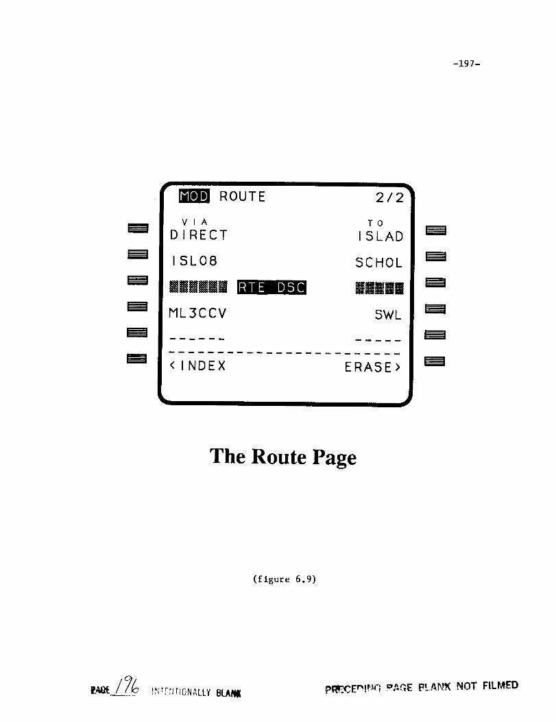
-197-
MOD ROUTE
VIA
DIRECT
ISL08
JJmNmm
ML3CCV
2/2
TOISLAD
SCHOL
IIIII
SWL
RTE DSC
<INDEX ERASE>
The Route Page
(figure 6.9)
pRI?CEnl_¢G o,_GE PLANK NOT FILMED


-199-
MODULE NAME:
FILE NAME:
PROCESS:
CALLED BY:
CALLING SEQUENCE:
ACT EXIT
ROUTE.FOR
SLOW
DATA IN
CALL ACT EXIT(INDEX)
PURPOSE:
To verify "dead waypoint" errors.
DESCRIPTION:
Dead waypoint errors occur when the pilot attempts
to delete overflown waypoints from the ROUTE page. The
module signals a dead waypoint situation when a DELETE
is placed at one of the route elements. However a dead
waypoint situation is flagged when the exit waypoint
of a route function that contains the active "To" way-
point is deleted. This procedure checks for that
special case and allows the exit waypoint deletion
instead of setting the error code.
GLOBAL REFERENCES:
VARIABLES
ACTCNT ERCODE* TOWPT
RECORD ARRAYS
RTE ACT RTE MOD* WPT ACT
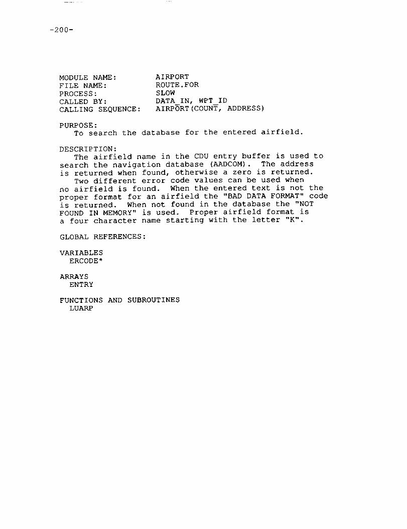
-2O0-
MODULENAME:FILE NAME:PROCESS:CALLED BY:CALLING SEQUENCE:
AIRPORTROUTE.FORSLOWDATA IN, WPT IDAIRPORT(COUNT, ADDRESS)
PURPOSE:To search the database for the entered airfield.
DESCRIPTION:The airfield name in the CDU entry buffer is used to
search the navigation database (AADCOM). The addressis returned when found, otherwise a zero is returned.
Two different error code values can be used whenno airfield is found. When the entered text is not theproper format for an airfield the "BAD DATA FORMAT" codeis returned. When not found in the database the "NOTFOUND IN MEMORY"is used. Proper airfield format isa four character name starting with the letter "K".
GLOBAL REFERENCES:
VARIABLESERCODE*
ARRAYSENTRY
FUNCTIONSAND SUBROUTINESLUARP
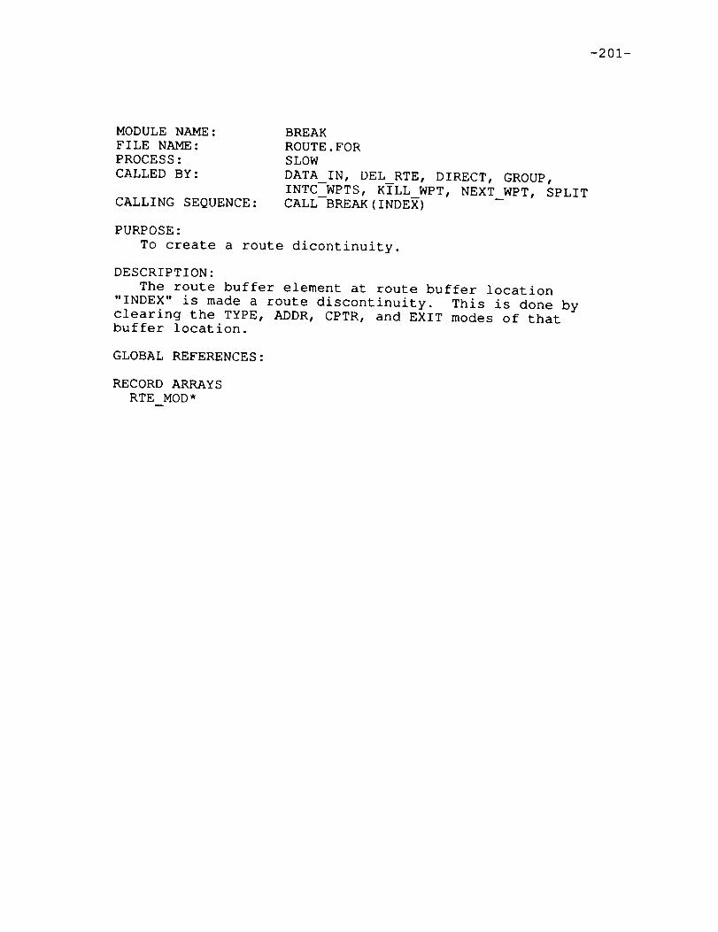
-201-
MODULENAME:FILE NAME:PROCESS:CALLED BY:
CALLING SEQUENCE:
BREAKROUTE.FORSLOWDATA_IN, DEL_RTE, DIRECT, GROUP,INTC_WPTS, KILL_WPT, NEXT_WPT, SPLITCALL BREAK(INDEX)
PURPOSE:To create a route dicontinuity.
DESCRIPTION:The route buffer element at route buffer location
"INDEX" is made a route discontinuity. This is done byclearing the TYPE, ADDR, CPTR, and EXIT modes of thatbuffer location.
GLOBAL REFERENCES:
RECORDARRAYSRTE MOD*
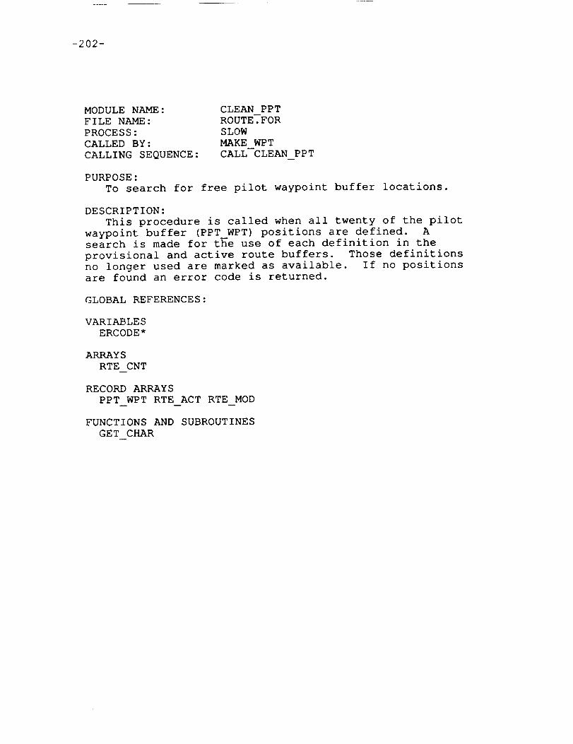
-202-
MODULENAME:FILE NAME:PROCESS:CALLED BY:CALLING SEQUENCE:
CLEAN PPTROUTE.FORSLOWMAKE WPTCALL CLEAN PPT
PURPOSE:TO search for free pilot waypoint buffer locations.
DESCRIPTION:This procedure is called when all twenty of the pilot
waypoint buffer (PPT WPT) positions are defined. Asearch is made for the use of each definition in theprovisional and active route buffers. Those definitionsno longer used are marked as available. If no positionsare found an error code is returned.
GLOBAL REFERENCES:
VARIABLESERCODE*
ARRAYSRTE CNT
RECORDARRAYSPPT WPT RTE ACT RTE MOD
FUNCTIONS AND SUBROUTINESGET CHAR
-203-
MODULENAME:FILE NAME:PROCESS:CALLED BY:CALLING SEQUENCE:
COMPANYROUTE.FORSLOWDATA INCALL COMPANY(NAMELENGTH)
PURPOSE:To insert a company route into the route buffer.
DESCRIPTION:This procedure is called when a company route is entered
on the ROUTEpage of the CDU. The length parameter passedis the number of characters in the global buffer, ENTRY,which contains the company route name.
Once the company route is found in the navigation data-base the default origin and destination airfields are set.Runway data for these airfields is invalidated. When anorigin airfield has already been entered on the CDU thedefault value must match or the company route entry isrejected. The company route SID and STAR pointers aretested for non-zero values. If supplied, the departure andarrival route functions are placed in the route buffer bycalling GROUP. The company route's list of waypoints areinserted into the route buffer after the SID and before theSTAR.
GLOBAL REFERENCES:
VARIABLESADDRESSERCODE*
ARRAYSAIRPTS* ENTRY RTE CNT
RECORDARRAYSRTE MOD*
FUNCTIONS AND SUBROUTINESGET LONG GROUPLURTE TYPE WPT

-204-
MODULENAME:FILE NAME:PROCESS:CALLED BY:CALLING SEQUENCE:
DATA INROUTE.FORSLOWROUTECALL DATA IN
PURPOSE:To parse route page keyboard data entries.
DESCRIPTION:This subroutine is called to parse keyboard data entries.
Function entries are handled by the main procedure ROUTEorthe module ECHO. These data entries are the names of routefunctions, waypoints, and runways. If route page #I is beingshown there are four entries which are made at fixedpositions on the screen. This includes the origin anddestination airfields, origin runway, and company route.The adjacent line select keys (LSKs) are used to modify theseitems. All other entries are waypoints, route functions, or'DELETE' entries which are enterd at various display linesvia the LSKs.
First, DATA IN checks for fixed position inputs. Theseare the originTdestination airfields, company route, andtakeoff runway. When a valid origin airfield is entered,the flight plan is initialized to be empty. When thedestination airfield is entered any previously existingtouchdown waypoints are removed from the plan. When acompany route is entered the entire flight plan is setupby a call to the module COMPANY. Valid takeoff runwayselicit a call to ORGRWYto generate the required runwaywaypoints.
The #6 LSK on the left hand side (LSK-L6) is used tochange to the ROUTE INDEX page. Data on the scratch padwhen this LSK is selected is not intended as a data entry.DATA IN detects this situation and responds by callingREPROGto restore the data to the scratch pad, and thensignals the page change request.
The processing of waypoints, route functions, andDELETE entries occurs next. Note that all route functionsare always entered with left LSKs and waypoints with rightLSKs. DELETE entries are made on either side. The LSKselected and the current ROUTEpage number are used toidentify a particular element in the route buffer. Theelement may already contain an entry or may be the nextavailable spot at the end of the buffer. Note that routebuffer elements corresponding to waypoints prior to thecurrent "To" waypoint on an active flight plan may notbe modified. Also the position imediately following aroute function with an undefined exit waypoint may notbe changed.
-205-
A left LSK is used when a route function or DELETE isentered. The DELETE entry will erase the route functionand replace it with a route discontinuity marker, unlessthe deleted item was the last in the buffer. When aroute function is entered, RTE ID is called to search thesystem database for the name and to identify its type(SID, STAR, ...). Two types of route function entries arepossible. If an individual route function name was entered,RTE ID set OFFSET to zero, the route function is made partof the flight plan by calling GROUP. An intercept routeentry of the form BEARING/ROUTENAME/EXIT WAYPOINT is alsoprocessed by RTE ID. In this situation the offset of theexit waypoint is returned to this procedure in the globalvariable OFFSET. The procedure RTE INTC is called insteadof GROUPfor the insertion of the intercept waypoint andthe route function waypoints.
A right LSK is used when a waypoint or DELETE entry ismade. DELETE can either erase the exit waypoint of a routefunction or a normal waypoint. Route discontinuity markersare inserted for DELETE entries unless the erased item was
the last in the buffer. When a waypoint name is entered,
WPT ID is called to search the system database and identify
the waypoint type (GRP, NAVAID, ...). If found the waypoint
information is inserted into the route buffer by callingWAYPOINT.
GLOBAL REFERENCES:
VARIABLES
ERCODE* PAGE PGRQST* PMODE PRMT TOWPT
ARRAYS
AIRPTS ENTRY RTE CNT*
RECORD ARRAYS
RTE MOD WPT ACT
FUNCTIONS AND SUBROUTINES
ACT EXIT AIRPORT BREAK COMPANY DEL IN DEL RTE EXIT GROUP
INIT PLAN LURWY OPEN ORG RWY REMOVE REPROG RTE ID RTE INTC
WAYPOINT WPT ID -- -- --

-206-
MODULENAME:FILE NAME:PROCESS:CALLED BY:
CALLING SEQUENCE:
DEL INROUTE.FORSLOWACTION, DATA_IN, DA_INPUT, FIX_INFO,FIX INP, FLT TYPE_INP, HOLD INPUT,IDENT, INDX_INPUT, INITUP, NAV INPUT,NMBRS, PFINP, SUBNAV_INPUT, TIME_IN,TKOFFINP, WPT DATABOOLEAN=DELIN()
PURPOSE:To identify DELETE entries.
DESCRIPTION:The CDU entry line buffer ENTRY is tested for "DELETE".
GLOBAL REFERENCES:
VARIABLESSTRING
ARRAYSENTRY

-207-
MODULENAME:FILE NAME:PROCESS:CALLED BY:CALLING SEQUENCE:
DEL RTEROUTE.FORSLOWDATAIN, MODIFYCALL DEL RTE(INDEX)
PURPOSE:To remove a route function from the route buffer.
DESCRIPTION:This procedure is called with a route buffer index
designating a route function which is to be removed fromthe route buffer. If it is the last route element inthe buffer it is simply removed. Otherwise a routediscontinuity is created in its place.
Note that the module XLAT RTE handles the clearingof the destination runway address save in AIRPTS.Therefore this module does not have to determine if thedeleted route function was an approach.
GLOBAL REFERENCES:
ARRAYSRTE CNT*
FUNCTIONS AND SUBROUTINESBREAK

-208-
MODULENAME:FILE NAME:PROCESS:CALLED BY:CALLING SEQUENCE:
DSC CHECKROUTE.FORSLOWDEMODECALL DSC CHECK
PURPOSE:To perform maintainance on the route buffer.
DESCRIPTION:Each time changes are made to the route buffer DSC CHECK is
called to determine if the route buffer manipulations--haveproduced route discontinuities which either appear at theend of the buffer or immediately following another discon-tinuity. Also checks are made to determine if the samewaypoint is placed in consecutive buffer locations. Whenany of these situations occur, the excess elements areremoved from the buffer.
GLOBAL REFERENCES:
ARRAYSRTE CNT*
RECORDARRAYSRTE MOD
FUNCTIONS AND SUBROUTINESGET LONG KILL

-209-
MODULENAME:FILE NAME:PROCESS:CALLED BY:CALLING SEQUENCE:
ECHOROUTE.FORSLOWROUTECALL ECHO
PURPOSE:To echo route element names to the scratch pad.
DESCRIPTION:LSK's are used on the ROUTEpage to select particular
route elements for use in the scratch pad. In this formthe LSK is used as a function entry since no scratch paddata is entered prior to selection. The route functionname is programmed into the scratch pad line as if theindividual characters were manually entered.
The PROGSCR routine is called to echo the names oforigin or destination airfields, direct waypoints, exitwaypoints, and route functions to the scratch pad. Thetype byte stored in the route buffer is used to determinehow many characters to echo for the various kinds ofwaypoints.
GLOBAL REFERENCES:
VARIABLESERCODE* PAGE
ARRAYSAIRPTS ENTRY RTE CNT
RECORDARRAYSRTE MOD
FUNCTIONSAND SUBROUTINESGET CHAR GET LONG PROGSCR TYPE WPT

-210-
MODULENAME:FILE NAME:PROCESS:CALLED BY:CALLING SEQUENCE:
ENTRY WPTROUTE?FORSLOWBOUNDS, GROUP, SEQUENCEOFFSET = ENTRY WPT(INDEX,ADDR,TYPE)
PURPOSE:To determine validity of a route buffer entry waypoint.
DESCRIPTION:This function is used to determine if a waypoint stored
in the route buffer can be used as the entry waypoint of aroute function. The offset from the start of the routefunction to the waypoint pointer is returned when the way-point is valid, otherwise zero is returned. See section1.5.1.1 for detatils of the database format for routefunction data.
There are three input parameters to ENTRY WPT. The firstis the index into the route buffer of the element to betested as an entry waypoint. Note that the selected routebuffer element may be either a waypoint or a route function.If it is a route function the exit waypoint is used for thevalidity test. When this situation occurs, two route functionsshare the same waypoint as a joint exit/entry. The remainingparameters are the address and type of the route functionstored in the navigation database.
GLOBAL REFERENCES:
RECORDARRAYSRTE MOD
FUNCTIONS AND SUBROUTINESGET LONG RTE WPT
-211-
MODULENAME:FILE NAME:PROCESS:CALLED BY:CALLING SEQUENCE:
EXITROUTE.FORSLOWDATA IN, EXECUTEr ROUTE, UPDATE, WAYPOINTBOOLEAN= EXIT(INDEX)
PURPOSE:
To check exit waypoint status.
DESCRIPTION:
The route element defined in the route buffer, location
INDEX, is tested to determine if it is a route function
with an undefined exit waypoint. If it is the function
returns the boolean value FALSE. Otherwise the return
value is TRUE.
GLOBAL REFERENCES:
RECORD ARRAYS
RTE MOD

-212-
MODULENAME:FILE NAME:PROCESS:CALLED BY:CALLING SEQUENCE:
EXIT WPTROUTE.FORSLOWGROUPOFFSET = EXIT WPT(INDEX,ADDR,TYPE)
PURPOSE:To determine validity of a route buffer exit waypoint.
DESCRIPTION:This function is used to determine if a waypoint stored
in the route buffer can be used as the exit waypoint of aroute function. The offset from the start of the routefunction to the waypoint pointer is returned when the way-point is valid, otherwise zero is returned. See section1.5.1.1 for detatils of the database format for routefunction data.
There are three input parameters to ENTRY WPT. The first
is the index into the route buffer of the ele--ment to be
tested as an entry waypoint. If this index points to an
unused buffer location or the element at the location is a
route function, the invalid status is immediately returned.
The remaining parameters are the address and type of the
route function stored in the navigation database. The
input data is passed on to the function RTE WPT to check
for validity as a route waypoint.
GLOBAL REFERENCES:
ARRAYS
RTE CNT
RECORD ARRAYS
RTE MOD
FUNCTIONS AND SUBROUTINES
RTE WPT
-213-
MODULENAME:FILE NAME:PROCESS:CALLED BY:CALLING SEQUENCE:
FIND PPTROUTE.FORSLOWPROCESS_GRP,UPDATE_POS, WPT_IDINDEX = FIND PPT(NAME)
PURPOSE:To locate a specific pilot defined waypoint.
DESCRIPTION:This function is called with the five character name
of a pilot waypoint. The pilot waypoint buffer (PPT WPT)is searched and the index into the structure is returned.A zero index value is returned when not found.
GLOBAL REFERENCES:
RECORDARRAYSPPT WPT

-214-
MODULE NAME:
FILE NAME:
PROCESS:
CALLED BY:
CALLING SEQUENCE:
FIND RTE
ROUTE.FOR
SLOW
RTE ID
ER_CODE = FIND_RTE (NAME, CNT, _dgDR, TYPE)
PURPOSE:
To locate a route function in the navigation database.
DESCRIPTION:
This function searches the system database for the
route function whose name and length are supplied as the
first two parameters in the calling sequence. The address
and route function type are returned through the parameter
list. The value returned through the function reference is
a CDU error code. If the value is zero, no errors were
detected.
An airway name consists of two to six letters, start-
ing with "J" or "V". SIDs, STARs, and APPROACHES have
five or six characters with no special starting letter.
Non-airway route functions are associated with particularairfields. The module LUSID is called to search _u_DCOM for
any SID/STAR/APPROACH at the destination airfield first.
Searching is complete if the item was found in the database
and the type of the located route function is not a SID,
since departures from the destination airfield may not be
referenced. Searching continues using the origin airfield
as reference. This time the only route function typeconsidered a valid find is the SID.
GLOBAL REFERENCES:
ARRAYS
AIRPTS
FUNCTIONS AND SUBROUTINES
LUJET LUSID LUVIC

-215-
MODULENAME:FILE NAME:PROCESS:CALLED BY:CALLING SEQUENCE:
GROUPROUTE.FORSLOWCOMPANY,DATA IN, MODIFY, RT NEWCALL GROUP(ADDR,TYPE, INDEX, APPEND)
PURPOSE:To insert a route function into the route buffer.
DESCRIPTION:This procedure enters a group of waypoints (route
function) into the route buffer. Processing varies forthe different route function types. In append mode thenew route function is simply added to the end of theroute buffer. Otherwise an insertion, possibly with thecreation of route discontinuities, into the buffer isperformed. When insertion occurs the following routeelements, including the one at the selected position,are moved ahead in the route buffer.
The parameter list in the call consists of four inputparameters. The first is the database address of theentered route function. Next is the route function typecode (defined in CDU.INC). The INDEX parameter points tothe destination slot in the route buffer for the enteredroute function. The last parameter is a flag indicatingwhen the append mode is active.
The previous route buffer element may be used as anentry waypoint into the entered route function. Thefunction ENTRY WPT is used to set the variable ENTRY OFSto the offset within the route function data to theentry waypoint. If the previous element cannot be usedas an entry waypoint, ENTRY OFS is zeroed. The followingchart describes how the different route function typesare handled by GROUP.
APPROACHES: When an entry waypoint does not already existin the route buffer, the first waypoint on the approachis used as a default. The last waypoint of the approachis always used as the exit waypoint, which automaticallyterminates the flight plan as the touchdown runway. Noroute discontinuities are generated from approach entries.
SID/STAR: The entry waypoint defaults to the first ofthe route function unless a valid entry waypoint wasfound in the route buffer. The following route bufferelement is checked for validity as an exit waypointfor the entered route function. If it cannot be usedthe default exit waypoint is the last waypoint on the
route function. No route discontinuities are generated
from SID/STAR entries.

-216-
AIRWAYS: An entry waypoint must have been explicitlydefined as the previous route element or the routefunction entry is rejected. When an airway is inserted(not appended) into the route buffer a route discon-tinuity marker is always inserted immediately followingthe entered route function. No default exit waypointis used and the next route buffer element is not con-sidered as a possible exit waypoint.
GLOBAL REFERENCES:
VARIABLESERCODE*
ARRAYSAIRPTS* RTE CNT*
RECORDARRAYSRTE MOD*
FUNCTIONS AND SUBROUTINESBREAK ENTRY WPT EXIT WPT GET LONGKILL OPEN REMOVETYPE WPT
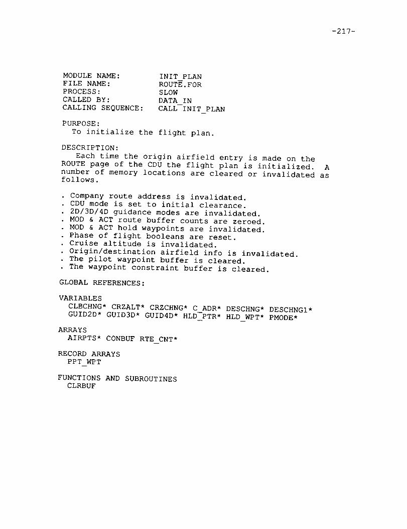
-217-
MODULENAME:FILE NAME:PROCESS:CALLED BY:CALLING SEQUENCE:
INIT PLANROUTE.FORSLOWDATA INCALL INIT PLAN
PURPOSE:To initialize the flight plan.
DESCRIPTION:Each time the origin airfield entry is made on the
ROUTEpage of the CDU the flight plan is initialized. Anumber of memory locations are cleared or invalidated asfollows.
Company route address is invalidated•• CDU mode is set to initial clearance.. 2D/3D/4D guidance modes are invalidated•
MOD & ACT route buffer counts are zeroed•MOD & ACT hold waypoints are invalidated•Phase of flight booleans are reset.Cruise altitude is invalidated•Origin/destination airfield info is invalidated.
• The pilot waypoint buffer is cleared•The waypoint constraint buffer is cleared•
GLOBAL REFERENCES:
VARIABLESCLBCHNG*CRZALT* CRZCHNG*C ADR* DESCHNG*DESCHNGI*GUID2D* GUID3D* GUID4D* HLD PTR* HLD WPT* PMODE*
ARRAYSAIRPTS* CONBUFRTE CNT*
RECORDARRAYSPPT WPT
FUNCTIONSAND SUBROUTINESCLRBUF

-218-
MODULENAME:FILE NAME:PROCESS:CALLED BY:CALLING SEQUENCE:
INTC WPTSRTE INTC.FORSLOWRTE INTCCALL INTC WPTS(LAT, LON,ENTRY,RTE ADR,
RTE_TYP,BUF_PTR,APPEND)
PURPOSE:TO store route intercept data into the route buffer.
DESCRIPTION:This module makes the insertions into the provisional
route buffer (RTE MOD) which reflect the route interceptdata generated when the "RTE INTC" option is selected on theRoute page. Four elements are inserted into the routebuffer.
i) A waypoint for the leg intercept point2) The entry waypoint onto the route3) The route function4) A route discontinuity separating the new data from the old
The first two items passed through the calling sequenceare the latitude and longitude of the intercept waypoint.The next item passed is the offset into the route functionof the route entry waypoint followed by the address and typeof the route function. Next is the index into the routebuffer where the insertion is to be made. The last parameteris a boolean flag indicating whether the additions are eitherinserted within the route buffer or appended onto the end.
The intercept waypoint is created in the Pilot DefinedWaypoint buffer with a call to MAKE WPT. The route functionentry waypoint is saved next, using the passed offset tofetch the address pointer to the actual waypoint. Thefunction TYPE WPT is used to determine what type of waypointthe entry waypoint is. The route function is stored by usingthe passed address and type. The global variable OFFSETalready contains the required exit waypoint offset, whichwas found when the route intercept entry was initiallyparsed. In the case of the Approach type of route function,the global exit offset is ignored and the last waypoint ofthe Approach is used as the exit. Also for an Approach thedestination runway is set and any route buffer elementspast the Approach are removed. The fourth addition to theroute buffer is a route discontinuity marker.
-219-
GLOBAL REFERENCES:
VARIABLESOFFSET
ARRAYSAIRPTS* RTE CNT*
RECORDARRAYSRTE MOD*
FUNCTIONS AND SUBROUTINESBREAK GET LONG KILL MAKE WPT OPEN TYPE WPT
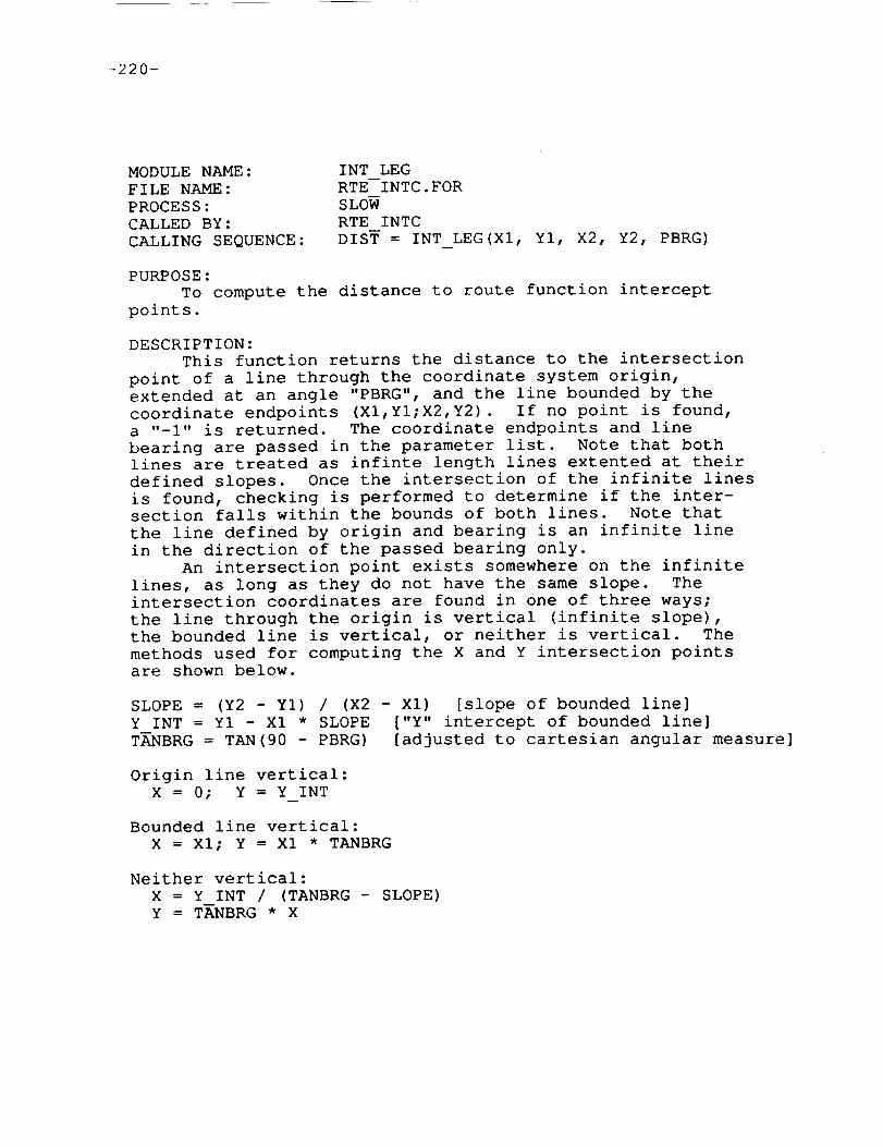
-220-
MODULE NAME:
FILE NAME:
PROCESS:
CALLED BY:
CALLING SEQUENCE:
INT LEG
RTE INTC.FOR
SLOW
RTE INTC
DIST = INT_LEG(Xl, YI, X2, Y2, PBRG)
PURPOSE:
TO compute the distance to route function intercept
points.
DESCRIPTION:
This function returns the distance to the intersection
point of a line through the coordinate system origin,
extended at an angle "PBRG", and the line bounded by the
coordinate endpoints (XI,YI;X2,Y2). If no point is found,
a "-i" is returned. The coordinate endpoints and line
bearing are passed in the parameter list. Note that both
lines are treated as infinte length lines extented at their
defined slopes. Once the intersection of the infinite lines
is found, checking is performed to determine if the inter-
section falls within the bounds of both lines. Note that
the line defined by origin and bearing is an infinite line
in the direction of the passed bearing only.
An intersection point exists somewhere on the infinite
lines, as long as they do not have the same slope. The
intersection coordinates are found in one of three ways;
the line through the origin is vertical (infinite slope),
the bounded line is vertical, or neither is vertical. The
methods used for computing the X and Y intersection pointsare shown below.
SLOPE = (Y2 - YI) / (X2 - Xl) [slope of bounded line]
Y_INT = Y1 - Xl * SLOPE ["Y" intercept of bounded line]
TANBRG = TAN(90 - PBRG) [adjusted to cartesian angular measure]
Origin line vertical:
X = 0; Y = Y INT
Bounded line vertical:
X = XI; Y = Xl * TANBRG
Neither vertical:
X = Y INT / (TANBRG - SLOPE)Y = TANBRG * X

-221-
Once the intersection point is found, it is determinedwhether the intersection point falls within the bounds ofthe actual lines. The function BETWEENchecks if the pointis on the bounded line segment. Since the bearing throughthe origin line does not actually extend in the reversedirection, the angle to the intersect coordinates is com-puted and compared to the original bearing to see that theymatch (are not 180 degrees out of phase).
GLOBAL REFERENCES:
FUNCTIONS AND SUBROUTINESANGL MTH$ATAND2MTH$SQRTMTHSTAND

-222-
MODULE NAME:
FILE NAME:
PROCESS:
CALLED BY:
CALLING SEQUENCE:
KILL
ROUTE.FOR
SLOW
BEG RTE, DSC CHECK, GROUP, HLD POS,
HOLD_INPUT, INTC_WPTS, LINK_PDTMERGE,
MODIFY, NEW_ENTRY, NEXT_WPT, REMOVE,TRIM WPTS
CALL--KILL(INDEX, COUNT)
PURPOSE:
To remove route elements from the route buffer.
DESCRIPTION:
"COUNT" route elements are removed from the route buffer
starting at the location INDEX. The created gap is removed
by shifting trailing elements back over the deleted ones.
GLOBAL REFERENCES:
ARRAYS
RTE CNT*
RECORD ARRAYS
RTE MOD*

-223-
MODULENAME:FILE NAME:PROCESS:CALLED BY:
CALLING SEQUENCE:
MAKE WPTROUTE.FORSLOWDIRECT, FILL_RTE, INTC_WPTS, INTERCEPT,MODIFY, ORGRWY, WAYPOINT, WPT IDADDR=MAKEWPT(LAT,LON,ALT,SPD,N--AME)
PURPOSE:To create pilot defined waypoints.
DESCRIPTION:This function is used to create waypoints in the pilot
waypoint buffer (PPT_WPT). The address of the createdwaypoint is returned to the caller.
The parameter list defines the characteristics of thecreated waypoint. The position is passed as the first twoparameters (latitude & longitude). Altitude and speedare optional parameters which become default waypointconstraints. The name parameter may be either a full fivecharacter name or just the three character name prefix.When the prefix is supplied a unique two digit sequencenumber is appended to the name. The CDU entry line whichprompted the creation of the pilot waypoint is saved inPPT WPT also for reference by the NAV DATA page.
When the pilot waypoint buffer is full, CLEAN PPT iscalled to remove waypoint definitions no longer used. Ifno space is found an error code is returned.
GLOBAL REFERENCES:
VARIABLESERCODESTRING
ARRAYSENTRY
RECORDARRAYSPPT WPT
FUNCTIONSAND SUBROUTINESCLEAN PPT ISTRNG P LIST

-224-
MODULENAME:FILE NAME:PROCESS:CALLED BY:CALLING SEQUENCE:
MERGEROUTE.FORSLOWWAYPOINTCALL MERGE(WPT_ADR,INDEX, LAST_INDEX)
PURPOSE:TO merge sections of the route buffer.
DESCRIPTION:
This subroutine is called to determine if the last
entered waypoint appears again further along on the flight
plan. This is interpreted as an attempt, by the pilot, to
eliminate the part of the flight plan in between. When
this situation is detected, the route buffer data in
between the two occurences (including one copy of the
repeat waypoint) is removed from the route buffer.
The address of the entered waypoint is passed as the
first call parameter. Its route buffer postion is
the second parameter and the third is the route buffer
position where searching should be terminated.
When the merge is performed the second copy of the
waypoint is thought to be moved up to a previous position,
removing elements in between. Therefore any waypoint
constraints associated with the original waypoint are
transfered to the new copy by calling XFER CON.
Complications arise when the route buffer elements
examined are route functions. Then the waypoints defined
between, and including, the exit and entry waypoints are
compared to the key waypoint. In this situation the
key waypoint becomes the new entry waypoint for thetested route function.
GLOBAL REFERENCES:
RECORD ARRAYS
RTE MOD
FUNCTIONS AND SUBROUTINES
BOUNDS KILL RTE WPT SEQUENCE XFER CON

-225-
MODULENAME:FILE NAME:PROCESS:CALLED BY:CALLING SEQUENCE:
NEWPOSROUTE.FORSLOWINTERCEPT, ORGRWY, WAYPOINT, WPT IDCALL NEW_POS(LATI,LONI,BRG, RNG,LA_2,LON2)
PURPOSE:To compute a position from a defined reference position.
DESCRIPTION:This procedure uses a reference position (LATI/LONI),
bearing (BRG), and range (RNG) from the parameter listto compute a new position which is returned through theparameter list (LAT2/LON2). The Path Definition procedure,LOCAL_ERAD, is called to find the local feet per degreevalues.
GLOBAL REFERENCES:
VARIABLESLAT FEET LON FEET
FUNCTIONSAND SUBROUTINESLOCAL ERAD SCOSD
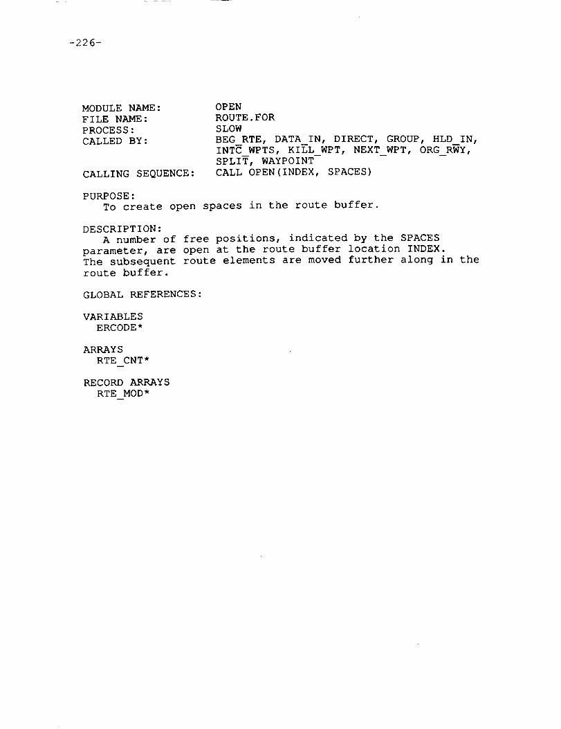
-226-
MODULE NAME:
FILE NAME:
PROCESS:
CALLED BY:
CALLING SEQUENCE:
OPEN
ROUTE.FOR
SLOW
BEG RTE, DATA_IN, DIRECT, GROUP, HLD_IN,
INTC_WPTS, KILL_WPT, NEXT_WPT, ORG RWY,SPLIT, WAYPOINT
CALL OPEN(INDEX, SPACES)
PURPOSE:
To create open spaces in the route buffer.
DESCRIPTION:
A number of free positions, indicated by the SPACES
parameter, are open at the route buffer location INDEX.
The subsequent route elements are moved further along in theroute buffer.
GLOBAL REFERENCES:
VARIABLES
ERCODE*
ARRAYS
RTE CNT*
RECORD ARRAYS
RTE MOD*

-227-
MODULENAME:FILE NAME:PROCESS:CALLED BY:CALLING SEQUENCE:
ORGRWYROUTE.FORSLOWDATA_IN, MODIFYCALL ORGRWY(ADDRESS)
PURPOSE:To insert an origin runway into the route buffer.
DESCRIPTION:This procedure is called with the address of a runway
in the navigation database. First any existing takeoffrunway waypoints are removed from the flight plan. Twowaypoints are inserted at the start of the route buffer.The first is placed at the position of the brake releasepoint on the runway and the second is placed three nauticalmiles ahead at an elevation of 1005 feet above the runway(3 degree ascent).
The two waypoints are actually pilot waypoints createdby calling MAKE WPT. Their names are "BRnnx" and "DPnnx"where "nn" is the runway number and "x" is the left, rightindicator "L" or "R". If it is the only runway with thatdirection at the airfield, the "x" character is shown as11XII .
GLOBAL REFERENCES:
ARRAYS
AIRPTS*
RECORD ARRAYS
RTE MOD*
FUNCTIONS AND SUBROUTINES
GET CHAR GET REAL MAKE WPT NEW POS OPEN REMOVE

-228-
MODULE NAME:
FILE NAME:
PROCESS:
CALLED BY:
CALLING SEQUENCE:
PROG SCR
ROUTE.FOR
SLOW
ECHO
CALL PROG SCR(STRING, LENGTH)
PURPOSE:
To program the CDU scratch pad.
DESCRIPTION:
The text passed to this module in the parameter STRING
is programmed into the scratch pad by calling FMTOUT.
GLOBAL REFERENCES:
FUNCTIONS AND SUBROUTINES
FMTOUT

-229-
MODULENAME:FILE NAME:PROCESS:CALLED BY:CALLING SEQUENCE:
REMOVEROUTE.FORSLOWDATA_IN, GROUP,MODIFY, ORG_RWY,WAYPOINTCALL REMOVE(RWYCODE)
PURPOSE:To remove runway waypoints from the flight plan.
DESCRIPTION:This procedure is called to remove either takeoff or
touch-down runway waypoints from the route buffer. Therunway code parameter selects which type to delete. Themodule checks the ".RWY" field of all the waypoints inroute buffer for RWYCODEmatches. The procedure KILLis called to remove the waypoints.
GLOBAL REFERENCES:
ARRAYSRTE CNT
RECORDARRAYSRTE MOD
FUNCTIONS AND SUBROUTINESKILL

-230-
MODULENAME:FILE NAME:PROCESS:CALLED BY:CALLING SEQUENCE:
ROUTEROUTE.FORSLOWSELECTCALL ROUTE
PURPOSE:To serve as the ROUTEpage executive procedure.
DESCRIPTION:This subroutine is the main procedure for the ROUTEpage
software. It performs a number of top-level functionsbeginning with first pass initialization and the computationof a few variables used by other modules. Most keyboardentries are handled by a call to DATA IN, however simplekeyboard requests such as page changes are performedinline. A call to the CDU screen update procedure (UPDATE)is made every time the CDU executive calls ROUTE. This isdone to periodically update lines of the CDU screen evenwhen no changes have been made.
Two items handled by ROUTE and used by other modulesare the prompt boolean and page count. The line followingthe last ROUTEpage entry may have dash prompts to indicatethe next available entry position. The flag PRMT is setwhen the prompt is valid. The conditions are as follows.
The flight plan does not end with a touchdown runway.The last item is either a route function completewith its exit waypoint or a single waypoint.origin and destination airfields are defined.
The LASTPG variable is computed as the number of ROUTEdisplay pages required to show all the route data,including the prompt text.
GLOBAL REFERENCES:
VARIABLESERCODE* LASTPG PAGE* PASS* PGINIT* PGRQST*PMODEPRMT
ARRAYSAIRPTS ENTRY* RTE CNT
FUNCTIONS AND SUBROUTINESDATA IN DEMODEECHOEXIT FMTOUTREJECT UPDATE

-231-
MODULENAME:FILE NAME:PROCESS:CALLED BY:CALLING SEQUENCE:
RTE IDROUTE.FORSLOWDATA IN RT NEWCALL RTE ID(COUNT, ADDRESS, TYPE)
PURPOSE:To identify a route function entry.
DESCRIPTION:This procedure is called when a route function name is
entered on the CDU. The navigation database is searched todetermine the validity of the entry.
The paramter list contains one input and two outputparamters. The count is the number of characters in theroute function name, which is stored in the global bufferENTRY. The route function address and type are returned tothe caller. When the route function is not found in memorya zero address value is returned.
Two formats for route function entry exist. The firstis the entry of a route function name only. In thissituation the function FIND RTE is called to search thedatabase for the entered name and the result is immediatelyreturned to the caller. The second format appears as threeitems, separated by slashes as follows.
BEARING/ROUTEFUNCTION NAME/EXIT WAYPOINTNAME
This format is used when a fixed intercept bearing from awaypoint, already part of the flight plan, onto a routefunction is desired. RTE ID parses this entry to separatethe three items. The bearing value is decoded and stored inthe global variable BEARING. The route function and exitwaypoint are then located in the system database and theoffset of the exit is found on the route function. Theroute function address and the exit waypoint offset arereturned to the caller through the global variables ADDRESSand OFFSET respectively.
GLOBAL REFERENCES:
VARIABLESBEARING ERCODE* INDAT OFFSET*
ARRAYSENTRY
FUNCTIONS AND SUBROUTINESFIND RTE LIB$LOCC OTS$CVT TU L RTE WPT WPT ID
-232-
MODULENAME:FILE NAME:PROCESS:CALLED BY:CALLING SEQUENCE:
RTE INTCRTE INTC.FORSLOWDATA INCODE=RTE_INTC(RTE_ADR,RTE_TYP,PTR,APPEND)
PURPOSE:To perform the route function intercept computations.
DESCRIPTION:This procedure is called when the Route Intercept
option is requested on the RTE page. Each leg of theselected route is tested for an intersection with a radialdrawn from the previous waypoint in the flight plan. Morethan one leg may be intersected so the nearest leg is used.Note that DME turn legs are never chosen.
The following list is a summary of the inputs and out-puts referenced in RTE INTC. These are accessed both ascalling parameters and global variables.
INPUTSBEARINGOFFSETRTE ADRRTE TYPBUF PTRAPPEND
Entered magnetic bearing to routeByte offset in database to exit waypointAddress of route in databaseType of routePointer to insert position in RTE bufferAppend to end of RTE buffer flag
OUTPUTSRTE MOD Updated provisional route buffer
First the position of the reference waypoint in theflight plan is fetched. The reference waypoint is the way-point immediately preceeding the position in the flight planwhere the route function intercept was entered on the RTEpage. The preceeding item in the route buffer may beanother route function. In this case the exit waypoint ofthe route function is used as the reference waypoint.
Each leg segment on the selected route function isprocessed to determine if an intercept point exists. Theprocedure XYPOS is called to find the North and East offsets(feet) from the reference waypoint to the leg segment way-points. The function INT LEG is called for each pair todetermine the existance of an intersection from thereference waypoint at the entered bearing. A "-I" isreturned from INT LEG when no intersection exists. Other-wise the distance from the reference waypoint to theintersection position is returned. The distance to theclosest intersection is saved.
-233-
When finished with all waypoints a check is made todetermine if an intersection has been found. If the legbelongs to an AIRWAY the exit waypoint is used to determinewhich direction to go from the intersect waypoint byselecting one of the leg endpoints. For unidirectionalroutes an error is flagged when the entered exit waypointwould cause the wrong direction to be made.
"NEW POS" is called to compute the position of theintersect waypoint and INTC WPTS inserts the appropriateroute elements into the route buffer.
GLOBAL REFERENCES:
VARIABLESBEARING OFFSET
RECORDARRAYSRTE MOD
FUNCTIONS AND SUBROUTINESGET LONG GET REAL INTC WPTSINT LEG MAGVAR NEWPOS XYPOS
-234-
MODULENAME:FILE NAME:PROCESS:CALLED BY:
CALLING SEQUENCE:CALLS TO:
RTE WPTROUTE.FORSLOWADD PLAN, ADD WPT, ENTRY_WPT,EXIT WPT,HLD_IN, KILL_CON, KILL WPT, MERGE,NEWCON, TRIM WPTS, WAYPOINTOFFSET = RTE_WPT(RTE_ADR,RTE_TYP, WPT_ADR)
PURPOSE:To determine if a particular waypoint is part of a data-
base route function.
DESCRIPTION:RTE WPT is called with the address and type of database
route function. The address of a waypoint is also passed.The waypoint pointers in the route function body are testedto determine if the input waypoint is one of the routewaypoints. If it is, the offset from the start of theroute function to the waypoint pointer is returned. Other-wise a zero value is returned (See the format of AADCOMroute function in section 1.5.1.1).
GLOBAL REFERENCES:
FUNCTIONS AND SUBROUTINESGET LONG

-235-
MODULENAME:FILE NAME:PROCESS:CALLED BY:CALLING SEQUENCE:
SEQUENCEROUTE.FORSLOWMERGE, WAYPOINTBOOLEAN=SEQUENCE(IN_OFFSET,INDEX)
PURPOSE:To determine proper waypoint sequence for a route function.
DESCRIPTION:This function returns a boolean result which informs the
caller whether the entry and exit waypoints assigned to aroute function are in the proper sequence. Anytime theentry and exit waypoints are identical the function returnsan invalid status. Airways and company routes are bidirec-tional so any pair may serve as entry/exit. SID/STAR/APPROACHroute functions have their waypoint order pre-defined by the order in the navigation database. Checks areperformed to affirm that the correct order is maintained.
The parameter list consists of two input parameters. Thefirst is the offset in the route function data block of theentry waypoint pointer. The second is the route buffer indexof the designated route function. SEQUENCEmay be calledwith the entry offset equal to zero. In this situation theentry offset is computed from the previous route bufferelement.
GLOBAL REFERENCES:
RECORDARRAYSRTE MOD
FUNCTIONS AND SUBROUTINESENTRY WPT

-236-
MODULENAME:FILE NAME:PROCESS:CALLED BY:CALLING SEQUENCE:
SLASHROUTE.FORSLOWWPT IDINDEX = SLASH(START_INDEX)
PURPOSE:
Search for the "/" character.
DESCRIPTION:
The CDU entry buffer is searched starting at the
character designated by the START INDEX parameter.
function returns the index of the first slash found.
zero is returned when one is not found.
GLOBAL REFERENCES:
ARRAYS
ENTRY
The
A
-237-
MODULENAME:FILE NAME:PROCESS:CALLED BY:
CALLING SEQUENCE:
TITLEROUTE.FORSLOWDSP_TIME, DSP_WPTS,REFRESH_HOLD,UPDATECALL TITLE(TEXT, COUNT,PAGE,LASTPAGE)
PURPOSE:To create the CDU page title line.
DESCRIPTION:This procedure generates title line data for several
of the CDU clearance pages. The page identification textis passed along with the current and last page numbers.
GLOBAL REFERENCES:
VARIABLESPMODE
FUNCTIONS AND SUBROUTINESFMTOUT

-238-
MODULENAME:FILE NAME:PROCESS:CALLED BY:
CALLING SEQUENCE:
TYPE WPTROUTE.FORSLOWCOMPANY,ECHO, EXPAND_RTE, FILL_RTE,GROUP, INT_RTE, NEW_ENTRY,RT_NEW,RTE, UPDATETYPE = TYPE WPT(ADDRESS)
PURPOSE:To determine waypoint type.
DESCRIPTION:The address of a navigation database waypoint is sent to
this function. TYPE WPT examines the data and returns tothe caller the waypoint type. The logic is outlined below.
NAVAID: If fourth byte of data < 0.AIRFIELD: If fifth byte of data is a blank.GRP: Otherwise.
GLOBAL REFERENCES:
FUNCTIONS AND SUBROUTINESGET BYTE

-239-
MODULENAME:FILE NAME:PROCESS:CALLED BY:CALLING SEQUENCE:
UPDATEROUTE.FORSLOWROUTECALL UPDATE
PURPOSE:To update CDU display lines for the ROUTEpage.
DESCRIPTION:This subroutine formats lines of data for the CDU
screen. The utility FMTOUTis used throughout to storedata in the proper format (see section 1.2.1). Page #Iof the ROUTEpage has its own unique format, while allother pages follow the same template. This module iscalled once per iteration of the CDU software. The callsare used in a cycle of seven steps. On each step adifferent section of the ROUTEpage display is updated.After every seven calls to UPDATEthe entire CDU screenwill have been refreshed. The operations performed oneach pass through this module are summarized below.
PASS #0: The title line is stored by a call to TITLE.Also the "Via" & "To" labels are sent to line #7 orline #i. Page #i displaces the labels to line #7.
PASS #i/page #i: The origin and destination airfielddata. Includes labels and airfield names. No air-field shown as dashes.
PASS #2/page #i: Company route label and name (or dashes).
PASS #3/page #i: Takeoff runway label and name (or dashes).
PASS #(4-5)/page #i and
PASS #(l-5)/not page #i: The various route elements for
the current page and pass. The following list shows
what may be displayed on any route page line.
Waypoint name under the "To" column. The label
"DIRECT" will automatically appear under the "Via"column.
. Route function name under the "Via" column. The
exit waypoint name, or box prompts, is shown under the
"To" column.
Route discontinuity marker. Shown with box prompts
if previous line does not contain a route function
with box prompts as the exit waypoint.

-240-
• Dash prompts for the first display line which doesnot contain any of the above. Only shown when thePRMT boolean is set.
• The line corresponding to the page/pass iteration isblanked when none of the above is shown.
PASS #6: The dash line and the "<INDEX" and "ERASE>" tags.
GLOBAL REFERENCES:
VARIABLESC ADR LASTPG PAGE PASS* PMODEPRMT
ARRAYSAIRPTS BOXESDASHESRTE CNT
RECORDARRAYSRTE MOD
FUNCTIONS AND SUBROUTINESEXIT FMTOUTGET LONG TITLE TYPE WPT

-241-
MODULENAME:FILE NAME:PROCESS:CALLED BY:CALLING SEQUENCE:
WAYPOINTROUTE.FORSLOWADD WPT, DATA IN, MODIFY, RT NEWCALL WAYPOINT(ADDR, TYPE, INDEX, APPEND)
PURPOSE:To insert a waypoint into the route buffer.
DESCRIPTION:This procedure enters a waypoint into the route buffer.
Processing varies for the different waypoint types. Inappend mode the new waypoint is simply added to the end ofthe route buffer. Otherwise an insertion, possibly with thecreation of route discontinuities, into the buffer isperformed. When insertion occurs the following routeelements, including the one at the selected position, aremoved ahead in the route buffer.
There are four input parameters to WAYPOINT. The firstis the database address of the entered waypoint. Next isthe waypoint type (GRP, NAVAID, ...). The third parameteris an index into the route buffer to the selected position.The last parameter is a flag used to identify append mode.
A special situation arises when a runway number isentered as a waypoint. Two waypoints are placed into theroute buffer and all following elements are deleted. Thetwo waypoints are created pilot waypoints given the namesAPnnx and TDnnx. The "nn" field is the runway number andthe "x" is either "L", "R", or "X" (left, right, neither) .The "TD" waypoint is placed at the runway touchdown pointand the "AP" waypoint is positioned three nautical miles outat an elevation of 1005 feet above the runway.
The remaining waypoint types are handled the same.First the append flag is tested. In this mode the enteredwaypoint is placed in the next available route bufferlocation. When not in append mode other tests must bemade.
If the waypoint is inserted at a route discontinuity, twothings can occur. If the entered waypoint is already in theroute buffer further along the flight plan, the route bufferelements between the insertion position and the nextoccurence of the waypoint are deleted and the discontinuityis removed. Otherwise the new waypoint is inserted at thedesired position, moving the following elements ahead oneposition, preserving the route discontinuity.
If the waypoint entry was not made to fill in anundefined route function exit waypoint, the waypointis inserted and a test is made to determine if the newwaypoint is a valid entry waypoint to a route functiondefined in the next location. If the next element is nota route function or the new waypoint does not qualify asan entry waypoint, a route discontinuity is insertedfollowing the new waypoint.
-242-
When the entry was made to fill in an undefined exitwaypoint, it is tested to verify its definition as partof the route function. For one-directional routefunctions (SID/STAR/APPROACH) a sequence check is madeto ensure the exit comes after the entry waypoint. Thelast step is to look ahead for another occurrence ofthe entered waypoint. If it does the waypoint up toand including the duplicate are removed.
GLOBAL REFERENCES:
VARIABLESERCODE*
ARRAYSAIRPTS* RTE CNT
RECORDARRAYSRTE MOD*
FUNCTIONSAND SUBROUTINESBREAK EXIT GET CHAR GET REAL MAKE WPTMERGENEWPOS OPENREMOVERTE WPT SEQUENCE

-243-
MODULENAME:FILE NAME:PROCESS:CALLED BY:
CALLING SEQUENCE:
WPT IDROUTE.FORSLOWADD WPT, DATA IN, RT_NEW, DIRECT,INITUP, WPTADDRCALL WPT ID(COUNT, ADDRESS, TYPE)
PURPOSE:To identify the entered waypoint name.
DESCRIPTION:This procedure is called when the name of a waypoint
is entered on the CDU. The system database (AADCOM)andthe pilot defined waypoint buffer (PPT_WPT) are searchedto determine validity and type of the waypoint. Notethat this module may create pilot waypoints for globalposition entries such as absolute LAT/LON.
There is one input and three output parameters in thecall list. The count value is the number of charactersin the waypoint name, which is stored in the globalbuffer ENTRY. The address and type parameters are filledin once the waypoint has been identified. If the waypointis not found, the address variable is returned to thecaller zeroed.
The clearance pages of the CDU allow the use of globalposition references where waypoint names are normallyentered. These are in the form LATITUDE/LONGITUDE orWAYPOINT/BEARING/KANGE. The first defines an absoluteglobal position in terms of geographic coordinates. Thesecond defines a position relative to a known referencepoint. When WPT ID is called with a global reference asthe waypoint name, the waypoint is first created in thepilot waypoint buffer. Then the address and type arereturned as if the waypoint had previously existed andwas found by the database search. When the relativereference form is used, the same validity checks are madefor the reference waypoint as is done for standard way-point identification.
The identification of waypoints depends on length andcontent of the entered waypoint name. The waypoint IDprocess is outlined below.
2 Character: Must be a runway number. A blank is appendedand the runway lookup utility is called.
3 Character: Either a runway or a Navaid. If the first
characer is a digit it is treated as a runway. Other-
wise the Navaid lookup utility is called.

-244-
4 Character: Either an airfield name or "PPOS". If the
entry is "PPOS" a pilot waypoint is created as mentioned
above. Note that the entry "PPOS"/BEARING/RANGE is a
a valid entry which creates two pilot waypoints. If
not "PPOS" the airfield lookup utility is called.
5 Character: Either a GRP or a previously created pilot
waypoint. First the GRP lookup utility is called. If
successful the GRP data is returned. If not, the pilot
waypoint lookup is invoked.
In all the above cases an error code is set when the various
lookup procedures do not find the waypoint name in the
database.
GLOBAL REFERENCES:
VARIABLES
ERCODE* LAT LON STRING
ARRAYS
AIRPTS ENTRY
RECORD ARRAYS
PPT WPT
FUNCTIONS AND SUBROUTINES
AIRPORT DEGVAL FIND PPT FLTVAL GET REAL LUGRP LUNAVA LURWYMAG VAR MAKE WPT NEW POS SLASH

-245-
MODULENAME:FILE NAME:PROCESS:CALLED BY:CALLING SEQUENCE:
XYPOSRTE INTC.FORSLOWRTE INTCCALL XYPOS(PTR,LAT,LON, X,Y)
PURPOSE:TO compute waypoint coordinate offsets.
DESCRIPTION:This procedure is passed an address pointer of a way-
point entry within a database route. Also a reference way-point's latitude and longitude are passed. The data for theroute waypoint is located in the database and it's LAT/LONcoordinates are fetched. The North and East offsets fromthe reference position are then calculated through a call tothe utility GRID.
GLOBAL REFERENCES:
FUNCTIONSAND SUBROUTINESGET LONG GET REAL GRID


-247-
Section 6.3.7 THE ROUTEINDEX PAGE
The ROUTE INDEX page is accessed via the "<INDEX" promptwhich appears on the lower portion of the ROUTE, LEGS, andLEGS TIME pages. It mainly serves as an index page withprompts which may be selected to activate other pages. Seefigure 6.10 on the following page.
The file RTENDX.FOR contains the two subroutines for theRoute Index page. The main module puts up a menu on the CDUscreen and accepts pilot entries. All the left hand LSKsare used for selection of CDU pages involved with flightplan creation and modification. The upper right side LSK isused to request the vertical profile generation process onthe current path (not implemented).
The two module discriptions are provided on the followingpages.
PRECEDING PAGE BLANK NOT FILMED


-249-
m
i
B
RTE
SELECT
<TIME
<WIND
<RTE LE6S
<ROUTE
<FROM WPT
INDEX 111
COMPUTE
VERT PATH>
i
The Route Index Page
(figure 6.10)
PAr,[ .... i__ i_'_: "_'O'N;'LLY BI.AIpR.ECE_Dit+G p,",,:iE _..J!.,,zr..!.'KNOT F_LMED

-251-
MODULE NAME:
FILE NAME:
PROCESS:
CALLED BY:
CALLING SEQUENCE:
PGA
RTENDX.FOR
SLOW
RTENDX
CALL PGA
PURPOSE:
A dummy module to be replaced by PGA4D algorithm when
complete.
Oq_ ,_IT_,tTION_tLY _tAMI pEEDING PAGe 8' ._,_ _,OT F!L_ED

-252-
MODULE NAME:
FILE NAME:
PROCESS:
CALLED BY:
CALLING SEQUENCE:
RTENDX
RTENDX.FOR
SLOW
CDUEXC
CALL RTENDX
PURPOSE:
To serve as the executive module for the ROUTE INDEX
page.
DESCRIPTION:
This module receives keyboard inputs and updates the
CDU screen for the ROUTE INDEX page. The following chartlists the enties processed by RTENDX.
Page change selections. If data exists, it is reprog-
rammed into the scratch pad. (LSK-LI through LSK-L5)
The PGA (dummy) module is called when requested.(LSK-RI)
A line of the display screen is updated every time
before exiting this module. The screen is completely
refreshed every eight calls. RTENDX has a static display
so no special processing occurs for the line updates.
GLOBAL REFERENCES:
VARIABLES
ERCODE* FROMPG* PGINIT* PGRQST*
ARRAYS
ENTRY*
FUNCTIONS AND SUBROUTINES
FMTOUT PGA REPROG
VARIABLES
ERCODE* FROMPG* PGINIT* PGRQST*

-253-
Section 7.0 THE INITIALIZATION AND REFERENCEPAGES
There are a group of CDU pages refered to as the initial-ization and reference pages. They are used for the settingof some initial aircraft parameters, and the inspection ofinformation pertaining to aircraft systems.
All but two of the pages are accessed through theINIT/REF index page which is selected by the INIT/REF keyon the CDU keyboard. The EPR Limit and Progress pages eachhave their own CDU key to provide direct access to the page.
The remainder of section seven contains descriptions ofthe INIT/REF CDU pages and the sofware modules which managethem.


-255-
Section 7.1 THE INIT/REF INDEX PAGE
The INIT/REF page, also called the "index" page, dis-
plays seven prompts for page changes and accepts a LineSelect Key (LSK) input directing a transfer to a corres-
ponding page. This page is, effectively, a "menu" page.
The diagram on the following page (figure 7.0) shows the
CDU page selections available on the INIT/REF index page.
The INIT/REF code consists of a single FORTRAN moduleon the file INITREF.FOR.


-257-
IN IT/REF
<IDENT
<POS
<PERF/BARO
<TAKEOFF
<APPROACH
<NAV DATA
SET
INDEX 1 / 1
STATUS >
TEST>
GPS>
The Init/Ref Index Page
(figure 7.0)
PRECEDING PAGE BLANK NOT FILMED

-259-
MODULE NAME:
FILE NAME:
PROCESS:
CALLED BY:
CALLING SEQUENCE:
INITREF
INITREF.FOR
SLOW
CDUEXC
CALL INITREF
PURPOSE:
TO display a menu of CDU pages and to enable their
selection by pressing the associated key.
DESCRIPTION:
The INIT/REF page, also called the INDEX page, displays
seven prompts for page changes and accepts a Line Select Key
(LSK) input to cause a transfer to one of those pages. The
code refreshes one CDU line per pass. When there is a
function key input, it is processed through a "calculated
goto" structure in which the appropriate page is called or
an error message displayed.
GLOBAL REFERENCES:
VARIABLES
ERCODE* PGINIT* PGRQST*
ARRAYS
ENTRY*
FUNCTIONS AND SUBROUTINES
FMTOUT REPROG
_. c_.._ i'__ii_i_iiU_'LL'_PRECEDING Pr_GE _:Atr.._N._ I_iOT FILMED

-261-
Section 7.2 THE SYSTEM IDENTIFICATION PAGE
The IDENT page is the startup CDU display; it is auto-
matically displayed at system startup and remains active
until the operator validates the time at key LSK-L5. The
operator may do so by entering a time through the scratch
pad or by pressing the key with a blank scratch pad. This
forces use of the time from the Data Acquisition System
(DAS). Date entry is optional. This display also includes
two page-request choices, INDEX and POS INIT, at key 6, left
and right. Refer to figure 7.1 on the following page.
The IDENT page is coded in a single FORTRAN module.
PR"E_EDING PAG_ BLAN1K NOT FI!.MErJ


-263-
IDENT 1/1
MODEL ENG I NES
NASA 515 JTSD-7NAV DATA DATE
TDWR DEN 061271910 P PROGRAM DAT E
• i * . i o • , , • o • • • , , • •
<IIR INDEX POS>
m
m
m
m
i
i
The System Identification Page
(figure 7.1)

-265-
MODULENAME:FILE NAME:PROCESS:CALLED BY:CALLING SEQUENCE:
IDENTIDENT.FORSLOWCDUEXCCALL IDENT
PURPOSE:To display startup data regarding the aircraft and the
software versions, and to take operator input for the timeand date.
DESCRIPTION:The IDENT page is automatically displayed at system
startup and it remains active until the operator validatesthe system time at key LSK-L5. No other action is accepteduntil this is done. An actual time may be entered in theform "nnnn:nn," or the key may be pressed with a blankscratch pad to force use of the Data Acquisition System(DAS) time.
Date entry is optional and any 8-character input isacceptable. The only other options on this page are thepage-request choices at key 6 (L & R) for the INDEX andPOS INIT pages.
GLOBAL REFERENCES:
VARIABLESERCODEHRSS MINS PGINIT* PGRQST* TIME TIME VLD
ARRAYSBOXES BULK ID ENTRY*
FUNCTIONSAND SUBROUTINESBCDTIM DEL IN FMTOUTFMTTIM REPROGTIMVAL
pAO£_(o t{ INTEnTIONaLLYBLA_


-267-
Section 7.3 THE REFERENCE NAVIGATION DATA PAGE
The REF NAV DATA page is used by the flight crew for
identification of items such as waypoints, navaids and
airports. If an item is requested via the CDU keypad,
it is looked up in AADCOM and if found, the appropriate
subpage is displayed. Information about the requested item
is displayed on the subpage and the symbol for the
requested item appears on the map display. If the item is
not found in AADCOM, an informative message is displayed.
The format of the NAV DATA "root" page is shown on the
follwing page (figure 7.2).
pA___. _NTENTION_LLY BLA_
PRECEDII_K_ PAGE BLANK NOT FILMED


-269-
REF NAV DATA I/I
WAY PO I NT NAVA I D
__-
A I R PO RT A I RWAY
<I/R INDEX
m
m
m
m
i
i
The Navigation DataPage
(figure 7.2)
pAG£_INIENIIONALL¥ BI._NII PRECEDING PAGE BLANK NOT FILMED


-271-
MODULE NAME:
FILE NAME:
PROCESS:
CALLED BY:
CALLING SEQUENCE:
AIR INPUT
AIRWAY.FOR
SLOW
NAVPG
CALL AIR INPUT
PURPOSE:
To handle CDU entries on the airway waypoint page.
DESCRIPTION:
This module handles CDU keyboard entries while on the
airway waypoint subpage of the NAV data page. The valid
entries are listed below. Note that only function entries
are allowed. If data is on the scratch pad when return to
the "root" page is requested, it will be reprogrammed onto
the scratch pad for use on the main NAV data page.
LSK-LI through LSK-L5
LSK-RI through LSK-R5
LSK-R6
NEXT
PREV
Echo waypoint name to scratch pad
Select map center waypoint
Erase airway waypoints
Next display page
Previous display page
Selecting a NAV format display center waypoint may be
done when one of the Map displays is in "North Up" mode.
The CDU display will show a "<CTR>" bug along side the
chosen waypoint. The Map center selection is passed to the
procedure SET CENTER to signal the displays. When exiting
from the airway waypoint display, LOKWPT is cleared to
remove the airway waypoints from the Map display.
GLOBAL REFERENCES:
VARIABLES
AIR ADR AIR CNT AIR LAST AIR PG AIR PTR* DISPST ERCODE*
PAGE* PGRQST*
ARRAYS
ENTRY LOKWPT*
FUNCTIONS AND SUBROUTINES
FMTOUT GET LONG NAME LEN REPROG SET CENTER
PAO_ 500 INTENTIONALLY BLAN_,',_,J_'. i_!.Ai'CX NOT FILMED

-272-
MODULE NAME:
FILE NAME:
PROCESS:
CALLED BY:
CALLING SEQUENCE:
AIR PAGE
AIRWAY.FOR
SLOW
NAVPG
CALL AIR PAGE
PURPOSE:
To display the airway waypoint page.
DESCRIPTION:
This module formats the CDU display data for the air-
way waypoints subpage of the NAV data CDU page. The entire
screen is refreshed in six consecutive passes through this
procedure. On pass "0" the title line and key labels are
sent out. On passes "I" through "5", the five line pairs of
the display page are filled with waypoint name and LAT/LON
values.
The waypoints of an airway are displayed in sets of
five. The "NEXT" and "PREV" page keys may be used to view
different sets of five waypoints within the airway. This
module uses the global variables AIR ADR and AIR PG to find
the waypoint information in AADCOM fur the current page.
The starting address of the airway is in AIR ADR and the
current airway waypoint page number is saved--in AIR PG.
The text "<CTR>" is shown on the right side of--the line
containing the selected Map center waypoint when one of the
Map display formats is in "North Up" mode. The global
variable DISPST (bit mask 2000 hex) indicates a "North Up"
Map. The index within the airway of the selected Map center
waypoint is obtained from the global variable AIR PTR.
GLOBAL REFERENCES:
VARIABLES
AIR ADR AIR CNT AIR LAST AIR PG AIR PTR DISPST
ARRAYS
DASHES
FUNCTIONS AND SUBROUTINES
FMTDEG FMTOUT GET LONG GET REAL NAME LEN

-273-
MODULENAME:FILE NAME:PROCESS:CALLED BY:CALLING SEQUENCE:
CLEAR ENTRYNAVPG.FORSLOW
CALL CLEAR ENTRY
PURPOSE:To fill the array OUTLINES with blanks.
DESCRIPTION:This routine blanks all the character data in the array
OUTLINES, so that all the old information can be removedfrom the REF NAV DATA page of the CDU display before newinformation is added.
GLOBAL REFERENCES:
VARIABLESOUTLINES*

-274-
MODULENAME:FILE NAME:PROCESS:CALLED BY:CALLING SEQUENCE:
LIST INPUTAIRWAY.FORSLOWNAVPGCALL LIST INPUT
PURPOSE:To handle inputs on the airway list page.
DESCRIPTION:This module handles CDU keyboard entries when on the
airway list subpage of the NAV data page. LSK-LI throughLSK-L5 and LSK-RI through LSK-R5 are used to echo airwaynames to the scratch pad. Other keys that are used areLSK-L6, LSK-R6, NEXT page, and PREV page. LSK-L6 is used totoggle between Jet and Victor airways. LSK-R6 returns tothe NAV Data "root" page.
Up to ten airway names are shown per CDU airway listpage. All the airway names in the current list (Victor orJet) may be viewed ten at a time using the NEXT and PREVkeys.
The airway name echoed to the scratch pad is obtainedfrom the navigation database (AADCOM). An index into thecurrent airway list is computed from the airway list pageindex and the line select key used. This index is passed tothe function NAMEPTR to obtain the address of the namewithin AADCOM.
Switching between Jet and Victor airway lists is doneby a call to SET LIST. The index of the desired list typeis passed to this procedure.
GLOBAL REFERENCES:
VARIABLESAIR CNT AIR LAST AIR PG AIR TYPE ERCODE*PAGE* PGRQST*
ARRAYSENTRY
FUNCTIONS AND SUBROUTINESFMTOUTNAMEPTR REPROGSET LIST

-275-
MODULENAME:FILE NAME:PROCESS:CALLED BY:CALLING SEQUENCE:
LIST PAGEAIRWAY.FORSLOWNAVPGCALL LIST PAGE
PURPOSE:To display the CDU airway list page.
DESCRIPTION:This module formats CDU display text for the airway
list subpage of the NAV Data page. The entire screen isrefreshed every six calls to this module. On pass "0" thetitle line and fixed labels are sent out. On passes "i"through "5" the available airway names for the current listtype (Jet or Victor) are shown, two per line.
The global variable AIR TYPE indicates which type listis being shown. The title iTne will contain the name ofthe current list type. Also the LSK-L6 label will containthe prompt to select the list type not currently chosen.
The variable "PASS" is used to keep track of where inthe update cycle the module is. When PASS indicates one ofthe five lines containing airway names should be updated, anindex into the airway list is computed for the two airwaynames which will be shown on that line. The functionNAME PTR is sent these indices to return the addresses inAADCOMof the names of the airways.
GLOBAL REFERENCES:
VARIABLESAIR LAST AIR PG AIR TYPE
ARRAYSDASHES
FUNCTIONS AND SUBROUTINESFMTOUTNAMEPTR

-276-
MODULENAME:FILE NAME:PROCESS:CALLED BY:CALLING SEQUENCE:
MAGVNAVPG.DOCSLOWPROCESSARP, PROCESS_GRP,PROCESS_NAYX = MAGV(LAT, LON)
PURPOSE:To format the magnetic variation for the given coordinates.
DESCRIPTION:This routine calls MAGVAR with a latitude and longitude to
compute the magnetic variation at a certain location. Then itconverts the value to character data and formats it for output.
GLOBAL REFERENCES:
FUNCTIONS AND SUBROUTINESFSTRNGMAGVAR

-277-
MODULENAME:FILE NAME:PROCESS:CALLED BY:CALLING SEQUENCE:
NAMELENAIRWAY.FORSLOWAIR INPUT AIR PAGELENGTH= NAME--LEN(WPTADDRESS)
PURPOSE:To find the length of a waypoint name.
DESCRIPTION:The address of a navigation database waypoint is sent
to this function. The function TYPE WPT is then called todetermine the type of the waypoint. --The length is assignedfrom type as follows.
NavaidAirfiedGRP
3 characters4 characters5 charcaters
GLOBAL REFERENCES:
FUNCTIONS AND SUBROUTINESTYPE WPT
-278-
MODULENAME:FILE NAME:PROCESS:CALLED BY:CALLING SEQUENCE:
NAMEPTRAIRWAY.FORSLOWLIST INPUT LIST PAGEADDRESS= NAMEPTR(INDEX)
PURPOSE:TO find an airway name within an airway list.
DESCRIPTION:This module returns the address of the airway name
which is located in the position within the current airwaylist indicated by the calling parameter, INDEX. If therequested position is past the end of the airway list, apointer to a blank character field is returned.
GLOBAL REFERENCES:
VARIABLESAIR ADR AIR CNT
FUNCTIONS AND SUBROUTINESGET LONG

-279-
MODULENAME:FILE NAME:PROCESS:CALLED BY:CALLING SEQUENCE:
NAV INPUTNAVPG.FORSLOWNAVPGCALL NAV INPUT
PURPOSE:To parse CDU keyboard entries for the main REF NAV DATA
page.
DESCRIPTION:This subroutine is called when a keyboard entry is detected
while on the main REF NAY DATA page. Valid entries on thispage are limited to the following:
• Requesting the INDEX page. If there is data in thescratch pad, it is reprogrammed into the scratch pad foruse by the requested page.
Requesting the display of information about any waypoint,navaid, airway, or airport which is contained in thenavigation database (AADCOM).
Upon receipt of a valid data entry, some initializationvariables are set, including the PAGE variable which is setto reflect the page number of the page appropriate for therequested item type. Note that information for a waypoint,navaid or airport can be requested using either LSK-LI,
LSK-L2, or LSK-RI, although the labelling of the LSKs
implies that a certain LSK must be used to request
information about a certain type of item. For airways
information, LSK-R2 is used exclusively•
GLOBAL REFERENCES:
VARIABLES
ERCODE* PGRQST*
ARRAYS
ENTRY
FUNCTIONS AND SUBROUTINES
DEL IN PROCESS AIRWAY PROCESS ARP PROCESS GRP PROCESS NAV
REPROG SET LIST

-280-
MODULENAME:FILE NAME:PROCESS:CALLED BY:CALLING SEQUENCE:
NAVPGNAVPG.FORSLOWCDUEXCCALL NAVPG
PURPOSE:To serve as the REF NAV DATA page executive module.
DESCRIPTION:This subroutine is the main procedure for the REF NAV
DATA page software. It performs a few top-level functionsbeginning with first pass initialization and the computationof a few variables used by other modules. Input to the REF
NAV DATA page is handled by the module NAV_INPUT, unless oneof the subpages is active. The procedure SUBNAV INPUT is
called for all subpages except for airway information. For
airways either AIR_INPUT or LIST_INPUT is called depending
on the airway information shown. The screen is updated by a
call to REFRESH except when on an airway subpage. Airway
data updates are made by a call to either the procedureAIR PAGE or LIST PAGE.
GLOBAL REFERENCES:
VARIABLES
PAGE PASS* PGINIT*
ARRAYS
ENTRY* OUTLINES*
FUNCTIONS AND SUBROUTINES
AIR INPUT AIR PAGE CLEAR ENTRY LIST INPUT LIST PAGE
NAV INPUT REFRESH SUBNAV INPUT

-281-
MODULENAME:FILE NAME:PROCESS:CALLED BY:CALLING SEQUENCE:
PROCESSAIRWAYAIRWAY.FORSLOWNAV INPUTCALL PROCESSAIRWAY
PURPOSE:To handle requests for the airway waypoints page.
DESCRIPTION:This module is called when an airway name is entered on
the NAV Data page of the CDU for display of the waypointscontained within it. Global variables are set up to enablethe airway waypoint display subpage. If the requestedairway is not found in the database an error code is setand the subpage is not enabled.
The following list of global variables are set by thisprocedure when the requested airway is found in the data-base.
AIR PG
AIR PTR
AIR CNT
AIR LAST
PAGE
LOKWPT
Current airway waypoints subpage isinitialized to the first page.Map center waypoint is initialized to thefirst waypoint on the airway.Number of waypoints on the airway is determinedby stepping through the database.Nuumber of subpages required to show all theairway waypoints, five per page.Set to "4" to indicate the airway waypoint page.is active from the NAV Data "root" page.The airway address and ID code are set in thisarray to cause the displays to place theselected airway on the Map format.
The subroutine SET CENTERis called to set the Map centerlatitude and longitude from the Map center waypoint index(AIR PTR). This is used by any Map display format in"North Up" mode.
GLOBAL REFERENCES:
VARIABLESAIR ADR AIR CNT AIR LAST* AIR PG* AIR PTR* ERCODE* INDATPAGE*
ARRAYSENTRY LOKWPT*
FUNCTIONS AND SUBROUTINESGET LONG LUJET LUVIC SET CENTER

-282-
MODULENAME:FILE NAME:PROCESS:CALLED BY:CALLING SEQUENCE:
PROCESSARPNAVPG.FORSLOWNAV INPUT, SUBNAVINPUTCALL PROCESSARP
PURPOSE:To locate an airport in the navigational database and
format information for display on the REF NAV DATA page.
DESCRIPTION:This routine is called to update the contents of the
array OUTLINES, which contains appropriate informationaldata for display on the REF NAV DATA page. Initially,this routine looks up an airport in the navigational database (AADCOM), with a call to LUARP. If found, itfetches informational data for that airport, performs anyformatting or character conversion and stores theinformation in the array, OUTLINES. It stores theaddress of the airport and an airport type code in LOKWPT,so that the airport can be displayed on the MAP displayformat. Also, the variables LATCEN and LONCENare set tothe latitude and longitude of the specified airport, forthe purpose of specifying the center of the MAP format.If the requested airport is not found in AADCOManappropriate error message is displayed.
Note that prior to looking up the airport in AADCOM,the previous item address is stored off. This handles theparticular case where airport information is currentlydisplayed and a different airport is requested. If the newairport is not found, the original information remains onthe CDU display. Then if a runway for the displayedairport is requested, the original airport address isavailable to look up the runway.
GLOBAL REFERENCES:
VARIABLESADDR ERCODE*LATCEN* LONCEN* NLAT NLON PAGE* PASS* TARP
ARRAYSENTRY LOKWPT* OUTLINES*
FUNCTIONS AND SUBROUTINESCLEAR ENTRY FMTDEGFMTOUTFSTRNGGET REAL LUARP MAGVGET WORDLUNAVA MAGV

-283-
MODULENAME:FILE NAME:PROCESS:CALLED BY:CALLING SEQUENCE:
PROCESSGRPNAVPG.FORSLOWNAV INPUT, SUBNAVINPUTCALL PROCESSGRP
PURPOSE:To locate a waypoint in the navigational database and
format information for display on the REF NAV DATA page.
DESCRIPTION:This routine is called to update the contents of the
array OUTLINES, which contains appropriate informationaldata for display on the REF NAV DATA page. Initially,this routine looks up a waypoint in the navigational data-base (AADCOM), with a call to LUGRP. If it is not found, itsearches for the requested waypoint in the pilot definedwaypoint buffer. If the waypoint is not located in eitherplace, an appropriate error message is displayed.
If the waypoint is found in either AADCOMor thepilot defined waypoint buffer, this routine then fetchesinformational data for that waypoint, performs any for-matting or character conversion and stores the informationin the array, OUTLINES. Note that the informationdisplayed for a pilot defined waypoint differs slightlyfrom the information diplayed for a waypoint which iscontained in the navigation database. In either case,this routine stores the address of the waypoint and awaypoint type code in LOKWPT, so that the waypoint can bedisplayed on the MAP display format. Also, the variablesLATCEN and LONCENare set to the latitude and longitude ofthe specified waypoint, for the purpose of specifying thecenter of the MAP format.
GLOBAL REFERENCES:
VARIABLESADDR ERCODE*LATCEN* LONCEN* NLAT NLON PAGE* PASS* TGRP
ARRAYSENTRY LOKWPT*OUTLINES*
RECORDARRAYSPPT WPT
FUNCTIONSAND SUBROUTINESCLEAR ENTRY FIND PPT FMTDEGFMTOUTLUGRPMAGV

-284-
MODULENAME:FILE NAME:PROCESS:CALLED BY:CALLING SEQUENCE:
PROCESSNAYNAVPG.FORSLOWNAV INPUT, SUBNAVINPUTCALL PROCESSNAV
PURPOSE:TO locate a navaid in the navigational database and
format information for display on the REF NAV DATA page.
DESCRIPTION:This routine is called to update the contents of the
array OUTLINES, which contains appropriate informationaldata for display on the REF NAY DATA page. Initially,this routine looks up a navaid in the navigational data-base (AADCOM), with a call to LUNAVA. If found, itfetches informational data for that navaid, performs anyformatting or character conversion and stores theinformation in the array, OUTLINES. It stores theaddress of the navaid and a navaid type code in LOKWPT,so that the navaid can be displayed on the MAP displayformat. Also, the variables LATCEN and LONCENare set tothe latitude and longitude of the specified navaid, forthe purpose of specifying the center of the MAP format.If the requested navaid is not found in AADCOManappropriate error message is displayed.
GLOBAL REFERENCES:
VARIABLESADDR ERCODE* LATCEN* LONCEN* NLAT NLON PAGE* PASS* TNAV
ARRAYSENTRY LOKWPT* OUTLINES*
FUNCTIONS AND SUBROUTINESCLEAR ENTRY FMTDEGFMTOUTFRMFRQFSTRNGGET BYTE GET REALGET WORDLUNAVAMAGV

-285-
MODULENAME:FILE NAME:PROCESS:CALLED BY:CALLING SEQUENCE:
PROCESSRWYNAVPG.FORSLOWSUBNAVINPUTCALL PROCESSRWY
PURPOSE:To locate a runway in the navigational database and
format information for display on the REF NAV DATA page.
DESCRIPTION:This routine is called to update the contents of the
array OUTLINES, which contains appropriate informationaldata for display on the REF NAV DATA page. This routinelooks up a runway in the navigational database (BulkData), beginning the search at a specified airport address,with a call to LURWY. If found, it fetches informationaldata for that runway, performs any formatting or characterconversion and stores the information in the array,OUTLINES. It stores the address of the runway and arunway type code in LOKWPT, so that the runway can bedisplayed on the MAP display format. If the requestedrunway is not found in AADCOMan appropriate errormessage is displayed.
GLOBAL REFERENCES:
VARIABLESADDR ERCODE*TRWY
ARRAYSENTRY LOKWPT*OUTLINES*
FUNCTIONSAND SUBROUTINESFSTRNGGET REAL LURWY

-286-
MODULENAME:FILE NAME:PROCESS:CALLED BY:CALLING SEQUENCE:
REFRESHNAVPG.FORSLOWNAVPGCALL REFRESH
PURPOSE:To update the CDU display for the REV NAY DATA pages.
DESCRIPTION:This subroutine updates the CDU display for the REF NAY
DATA page with calls to FMTOUT. The entire screen is updatedevery sixteen consecutive calls to this subroutine. The valueof PASS determines which particular lines are updated. Duringthe first call of the cycle, the page title is output alongwith an indication of the current and last page numbers.Information about the requested item is displayed on lines #ithrough #10. Line #II contains dashes and line #12 contains alabel for the LSK which provides access to the INDEX page. Ifinformation is presently being displayed on the REF NAY DATApage, then line #12 also contains a label for the LSK whichenables the erasure of the information.
GLOBAL REFERENCES:
VARIABLESPAGE PASS*
ARRAYSDASHESOUTLINES
FUNCTIONSAND SUBROUTINESFMTOUT

-287-
MODULENAME:FILE NAME:PROCESS:CALLED BY:CALLING SEQUENCE:
SET CENTERAIRWAY.FORSLOWPROCESS_AIRWAY,AIR__INPUT, NAVPGCALL SET CENTER
PURPOSE:To set the Map center LAT/LON.
DESCRIPTION:This module fetches the latitude and longitude of the
airway waypoint chosen as the Map center position. Theglobal variable AIR PTR is the index of the waypoint withinthe currently displayed airway. The variables LATCEN andLONCENare set for use by the NAV display format. Thevalues are found by using the start address (AIR ADR) andan offset computed from the Map center index to access thewaypoint address. See the database description (AADCOM)in section 6.1.1 for the structure of airways within thedatabase.
GLOBAL REFERENCES:
VARIABLESAIR ADR AIR PTR GDTIME* LATCEN* LONCEN*
FUNCTIONSAND SUBROUTINESGET LONGGET REAL

-288-
MODULE NAME:
FILE NAME:
PROCESS:
CALLED BY:
CALLING SEQUENCE:
SET LIST
AIRWAY.FOR
SLOW
NAV INPUT LIST INPUT
CALL SET LIST(AIRWAY TYPE)
PURPOSE:
To handle requests for the airway list page.
DESCRIPTION:
This procedure is called to enable the airway list
page, when LSK-R2 is pressed with no data on the
scratch pad, on the NAV Data page of the CDU. It is passed
the type of airway list desired in the calling sequence
(0: Jet airway I: Victor airway).
The following global variables are set up by this
procedure to enable the airway list page.
AIR PG
AIR TYPE
AIR ADR
AIR CNT
AIR LAST
PAGE
The current airway list subpage is initial-
ized to the first one.
Set to the index of the requested list type
(Jet or Victor).
Set to the starting address within the data-
base of the airway list.
Set to the number of airways in the list.
Set to the number of pages required to show
all the airway names in the list (I0 per page).
Set to "5" to indicate the airway list page of
the NAV data page is enabled.
Refer to section 6.1.1 for the structure of airway lists
in the navigation database (AA/]COM).
GLOBAL REFERENCES:
VARIABLES
AIR ADR AIR CNT AIR LAST* AIR PG* AIR TYPE* JPTR PAGE* V]?TR
FUNCTIONS AND SUBROUTINES
GET LONG

-289-
MODULENAME:FILE NAME:PROCESS:CALLED BY:CALLING SEQUENCE:
SUBNAVINPUTNAVPG.FORSLOWNAVPGCALL SUBNAVINPUT
PURPOSE:TO parse CDU data entries for the navaid data subpage,
the waypoint data subpage or the airport data subpage ofthe REF NAV DATA page.
DESCRIPTION:This subroutine is called when a data entry is detected
while on one of the three informational subpages of the REFNAV DATA page. Valid entries on this page are limited tothe following:
Requesting the INDEX page. If there is data in thescratch pad, it is reprogrammed into the scratch pad foruse by the requested page.
Requesting the display of information about any waypoint,navaid or airport which is contained in the navigationdatabase (AADCOM). Upon receipt of a valid dataentry, some initialization variables are set, includingthe PAGE variable which is set to reflect the page numberof the page appropriate for the requested item type.Note that information may be requested for a waypoint,navaid or airport from any of the three informationalsubpages.
. Erasing the display of waypoint, navaid or airportinformation. The main REF NAV DATA page is then displayedand the item is also removed from the MAP display format.
If information on an airport is curently displayed, theninformation about a particular runway may be requested.
GLOBAL REFERENCES:
VARIABLESERCODE* PAGEPGINIT* PGRQST*
ARRAYSENTRY LOKWPT*
FUNCTIONSAND SUBROUTINESDEL IN FMTOUTPROCESS_ARPPROCESS_GRPPROCESS_NAYPROCESS_RWYREPROG


-291-
Section 7.4 THE INITIAL POSITION PAGE
The "Initial Position" page, labelled INITPOS, displaysthe aircraft geographical position and groundspeed andallows the operator to initialize or modify the positionestimate. It also, on request, displays the location of anyreference point in the database. Refer to figure 7.3 onthe following page.
The INITPOS page is coded in three FORTRANsubroutineson the file INITPOS.FOR (INITPOS, INITUP, and STRIPR).
PAt_ ._c_ 0 INTENTIONALLY B'I.AI:_ ,_:__:_:_,_ E'A,,i,_ .Ft&rA_, NOT FILMED


-2 93-
m
m
i
m
m
PO.5 INIT 1/1
FMC PO S G S 200KTN34" 00' 00" W075" 00' 00"
ADI RS POS G$ 200KT
N34"00'02" W075"59' 59"R E F PO I NT CCV
N37°20'54 '' W075"59' 59"
<IIR INDEX ROUTE>
The Position Initialization Page
(figure 7.3)
PA_I_ 59 _ INILNIIUNALLY BLAN¢_


-295-
MODULENAME:FILE NAME:PROCESS:CALLED BY:CALLING SEQUENCE:
INITPOSINITPOS.FORSLOWCDUEXCCALL INITPOS
PURPOSE:A)
B)
C)
Permits the operator to initialize or modify the
aircraft position estimate.
Displays the aircraft position and groundspeed.
Displays the location of any reference point in the
database, in response to an operator request.
DESCRIPTION:
INITPOS nominally refreshes one CDU line per iteration,under the control of a "calculated GOTO" structure. If
there is user input, subroutine INITUP is called first to
take care of that.
The discrete POSMOD controls the display in several
respects, both in the main routine and in INITUP. It is set
in INITUP when the operator inputs a valid Lat/Lon to update
the computed aircraft position. While it is TRUE, the word
"MOD" is displayed in reverse video on the title line of the
CDU. Also, for the FMC position on line #2, the user's input
is held on static display in reverse video until it is
either accepted or rejected by the user. Finally, on line
#12, the prompts "<ERASE" and "ACCEPT>" are displayed in
place of the usual page change prompts.
Page refreshing is otherwise straightforward except that
position validity is verified by checking the discrete INAVV
and/or LLINIT, and the reference point status by checking
LINE6 ACT. If the FMC position hasn't been initialized, it
is displayed as boxes, indicating that the initialization is
required. At line #5, if a reference point has not been
displayed earlier, the label is output as dashes and the
coordinates line is left blank.
GLOBAL REFERENCES:
VARIABLES
GS GSINS INAVV LAT LATINS LATMP LINE6 ACT LLINIT LON LONINS
LONTMP PGINIT* POSMOD RFCNT
ARRAYS
DASHES ENTRY* LATADIR LATFMC LATRF LONADIR LONFMC LONRF RFID
FUNCTIONS AND SUBROUTINES
FMTDEG FMTOUT INITUP OTS$CVT L TI

-296-
MODULENAME:FILE NAME:PROCESS:CALLED BY:CALLING SEQUENCE:
INITUPINITPOS.FORSLOWINITPOSCALL INITUP
PURPOSE:To process function key and scratch pad input.
DESCRIPTION:Subroutine INITUP processes user input which might be
either a position update from the scratch pad, or a functionkey command. INITUP is structured as a nested IF/ELSEcommand. At the first level, the "IF" block processesfunction key inputs, and the "ELSE" block handles data inputfrom the scratch pad. In each case, all the function keysare checked. Error messages are sent out for bad data andfor invalid keys. When a position update or display iscalled for, FMTDEG is called to generate a latitude and
longitude. Then STRIPR is called to reformat the position
data and display it on the scratch pad. The flag POSMOD is
set when a position update is in progress and it subsequen-
tly controls the interpretation of key input in most cases.
GLOBAL REFERENCES:
VARIABLES
ERCODE* IDDLAT* IDDLON* INAVV INDAT LAT LATINS LATMP LINE6 ACT*
LLINIT LON LONINS LONTMP PGRQST* POSMOD* RFADDR RFCNT
ARRAYS
ENTRY LATADIR LATFMC LATRF LONADIR LONFMC LONRF RFID*
FUNCTIONS AND SUBROUTINES
DEGVAL DEL IN FMTDEG GET REAL REPROG STRIPR WPT ID
-297-
MODULENAME:FILE NAME:PROCESS:CALLED BY:CALLING SEQUENCE:
STRIPRINITPOS.FORSLOWINITUPCALL STRIPR
PURPOSE:To remove degree, minute, and second symbols from the
byte strings for latitude and longitude and then to printthe position information on the scratch pad as:Nddmmss/Eddmmss.
DESCRIPTION:The digits of the latitude and longitude are read into
a byte buffer, a slash is inserted between them, and FMTOUTis called to print the position on the scratch pad.
GLOBAL REFERENCES:
FUNCTIONSAND SUBROUTINESFMTOUT

-299-
Section 7.5 THE EPR LIMIT PAGE
The engine pressure ratio (EPR) limits are calculatedin subroutine EPRLMT. The EPRLIM page displays the four EPRlimits, for go-around, maximum continuous thrust, climb, andcruise. It also permits the operator to change the activelimit by pressing the line select key adjacent to the desiredlimit. The active limit is indicated by the "<ACT>" flagnext to it. Additionally, the current EPR for each engineis listed at the bottom of the display. Refer to figure7.4 on the following page.
This routine is coded in one FORTRANsubroutine titledEPRLIM.
pi:_CEDING PAGE BLANK NOT FILMED
P_ ._)Fc__INTENTIONALLY BLAf_


-301-
m
m
EPR LIMIT 111
GA 1. 983
MCT 1. 940
C LB 1. 965
CRZ 1. 900
1. 954 1. 953EPR 1 EPR 2
<ACT>
The EPR Limit Page
(figure 7.4)
r-_. aw.r',)P.M_ -zJO0 INTENTIONALLY BI.AIW PRECE_liqG PAGE i_l./__ NO; ,-.L,_,


-303-
MODULE NAME:
FILE NAME:
PROCESS:
CALLED BY:
CALLING SEQUENCE:
EPRLIM
EPRLIM.FOR
SLOW
CDUEXC
CALL EPRLIM
PURPOSE:
To print the engine pressure ratio (EPR) limits on the
EPRLMT display and to permit manual selection of the EPR
limit for auto-throttle operations.
DESCRIPTION:
This routine displays EPR limits; it does not compute
them. That is done separately by subroutine EPRLMT.
As illustrated in figure 7.4, the EPR limits are
displayed for go-around, maximum continuous thrust, climb,
and cruise. Additionally, the current EPR for each engine is
displayed at the bottom of the screen.The code first checks for a function key input,
accepting keys L1 through L4 only. If a valid key was
pressed, the global EPRFLG is set to a number signifying the
selected EPR. If no key was pressed, the routine refreshes
one line of the display per pass. The flag "<ACT>" is shown
adjacent to the selected EPR limit as dictated by EPRFLG.
GLOBAL REFERENCES:
VARIABLES
EC6 EPRI EPR2 EPRPLG ERCODE* GAEPR MCLEPR MCREPR MCTEPR PGINIT*
AR_YS
ENTRY*
FUNCTIONS AND SUBROUTINES
FMTOUT OTS$FLOAT
PAOE _O_ INTENTIONALLY _AIW PRECEDING PAGE BLANK NOT FILMED


-305-
Section 7.6 THE PROGRESS PAGE
The position of the aircraft and key navigation data
relative to the flight plan are presented on the two
PROGRESS pages. In particular, page 1 displays data
pertinent to the active waypoint and to the active 2D, 3D,
or 4D flight path. Page two displays the current position
estimate and the currently selected navaids. This page also
allows the user to transfer the position or DME data to the
scratch pad and to manually reset DME 2 or DME 3. Manual
tuning mode can be toggled to automatic mode, or vice versa,
by pressing the delete key followed by the appropriate line
key. Both pages offer a page change to the Climb, Cruise,
or Descent pages as appropriate for the current flight
phase. Refer to figures 7.5 and 7.6 on the following pages.
This display is coded in two FORTRAN subroutines,
PROGRESS and ACTION, in the file PROGRESS.FOR.
PAGf. ._O c/ I_IILNTIONALLV 8LANI{ PRECEDI_iG PAGE BLAN_ NOT FILMED


-307-
m
s
i
m
m
m
WPT
LFIALT
500OFT
AE
1.0Hi
PROGRESS
DTG
3.3NMFPA
0.4"FPAE
+ 0 O"
1/2
ETA
1557' 56XTKE
O. 82RTKAE
3.1"
RTA
TMER
14NM TO RTA
1100:00
+0:00:00
WFBBFGS 200KT
8SE OKT
<CLB
m
m
m
m
m
I
The Progress Page(#1)
(figure 7.5)
PAOE _0_ IN'rFNTIONALLY _AM
PRECEDING PAGE BLAi'q_K NOT F!'__'ED


-309-
m
I
m
_m
B
PROGRESS 2/2
PPOS
N34 ° 00' O0"DME 2
ORF 1 16.gOANEXT 2
HCM 108. 80NAV SOURCE
IDD
W075 ° 00' 00"DME 3
LFI 112.30A
<CLB
The Progress Page(#2)
(figure 7.6)
PAOE _0_3_ iNTENTIONALLY B1At_ PRECED|I_,IG PAGE BLANK NOT FILMED


-311-
MODULE NAME:
FILE NAME:
PROCESS:
CALLED BY:
CALLING SEQUENCE:
ACTION
PROGRESS.FOR
SLOW
PROGRESS
CALL ACTION(PASS,PAGE1)
PURPOSE:
To process user input for the PROGRESS page.
DESCRIPTION:
In subroutine ACTION, function key input is processed
first, beginning with the functions common to both pages.
This includes page requests (CLB, CRZ, DESC) and toggling
between PROGRESS pages 1 and 2. Since no other function is
valid for page i, processing continues for page 2. For keys
L1 and RI, the position coordinates are moved to the scratch
pad. For keys L2, R2, and L3, the station identifier is
moved to the scratch pad.
For data input, which is allowed only on page 2 and
only for the navaid identifiers on line 4 (keys L2 & R2),
three letter inputs are used to find the address of a new
navaid. Otherwise, if the DELETE key was pressed and manual
tuning was in effect, then auto-tuning is enabled. Any
other keys or conditions result in an error message.
GLOBAL REFERENCES:
VARIABLES
ATNAV2* ATNAV3* ATUNE2* ATUNE3* ERCODE* GUID2D INAVV LAT
LLINIT LON NVAD2A* VAD2B NVAD3A* PGRQST* TOWPT
ARRAYS
ENTRY*
RECORD ARRAYS
WPT ACT
FUNCTIONS AND SUBROUTINES
DEL IN FMTDEG FMTOUT GET CHAR GET WORD LUNAVA REPROG STRIPRm __ __
FR'ECEDI?,)G P,%GE Bt.Ai_ NOT F!LMED
-312-
MODULE NAME:
FILE NAME:
PROCESS:
CALLED BY:
CALLING SEQUENCE:
PROGRESS
PROGRESS.FOR
SLOW
CDUEXC
CALL PROGRESS
PURPOSE:
A) To display data on the active waypoint and the active
2D, 3D, or 4D flight path.
B) To display and allow changes to the tuning of the
navigation radios.
C) To determine which page change prompt to offer, and to
request that change in response to key input.
DESCRIPTION:
The PROGRESS page 1 allows the flight crew to observe
data pertinent to the active waypoint and to the active 2D,
3D, or 4D flight path. Page 2 displays the aircraft
position estimate and the selected navaids. It also
implements manual tuning of the navigation radios and an
option is provided to toggle the radio tuning mode between
manual and automatic.
Both pages use LSK-L5 to request transfer to the Climb,
Cruise, or Descent pages. Which of the three is determined
by external conditions [WPT ACT(TOWPT-I).PHASE].
On page I, all other line select keys (LSKs) are non-
functional. On page 2, the operator may transfer the
Lat/Lon or any of the three Navaid identifiers to the
scratch pad. Page 2 updates are done by selecting the
appropriate LSK when there is valid data on the scratch pad.
The "next #2 navaid" cannot be updated by the user.
When either active Navaid is in manual tuning mode, it can
be reset to auto by pressing the DELETE key followed by the
appropriate LSK.
The code is structured so that on any operator inter-
action subroutine ACTION is called to process the input,
after which subroutine PROGRESS terminates. If there is
no input, then the routine computes and refreshes one CDU
line per pass. Which page to update is determined by the
discrete PAGE1, which, in turn, is toggled when the user
presses the NEXT or PREY key on the CDU panel.
There are two "calculated goto" structures, one for
each page, followed by a correspondingly labelled code block
for each line on each page. The progress data and their
meanings are outlined below:

-313-
PAGE I: Label Source or Meaning
Line 2: WPT =DTG =ETA =
WPT ACT(TOWPT).NAMEDTOGOconverted to nautical miles(DTOGO/GSFPS)+ TIME
Line 4 : ALT =FPA =XTKE =
ALTCORGAMMAXTK x FTONM,"R" if XTK > 0.Blank if not at least 2D guidance.
Line 6: AE =FPAE =
TKAE =
Lines 8-10:
RTA
HER, "LO" if HER > 0.
PFPA - GAMMA, "+" if > 0.
TKE, "R" if > 0.
Blank if not at least 2D guidance.
Done through calls to Climb page
(RTA_LN8, RTA_LN9, RTA_LNI 0)
NOTE: If no RTA is available, "NO RTA ASSIGNED" appears on
line 8, and lines 9-11 are blank.
PAGE 2: Label
Line 2: PPOS =
Line 4:
Line 6:
Line 7:
LINE 12:
DME 2
ID =
FREQ =
DME 3
ID =
FREQ =
NEXT 2
ID =
FREQ =
NAV SRC =
Prompt =
Source or Meaning
LAT, LON
Blank if no valid position estimate.
NAVAD2A
ATUNE2,
"A" if ATNAV2 AND DME2FQ = ATUNE2
"M" if NOT ATNAV2
NAVAD3A
ATUNE3,
"A" if ATNAV3 AND DME3FQ = ATUNE3
"M" if .NOT. ATNAV3
NAVAD2B
NAVAD2B + 4
NAVTYP
Both pages:
WPT ACT(TOWPT-I).PHASE
If = 1 then use <CLB
If = 2 " " <CRC
If = 3 " " <DES
But no prompt if not at least
2D guidance.

-314-
GLOBAL REFERENCES:
VARIABLESACTCNT ALTCOR ATNAV2 ATNAV3 ATUNE2 ATUNE3 DME2FQDME3FQDTOGOGAMMAGSFPS GUID2D GUID3D HER INAVV LAT LLINIT LON NVAD2ANVAD2B NVAD3A PFPA PGINIT* TIME TKE TOWPTXTK
ARRAYSDASHESENTRY NAVTYP
RECORDARRAYSWPT ACT
FUNCTIONS AND SUBROUTINESACTION FMTDEGFMTOUTFMTTIM FRMFRQGET CHARGET WORD
OTS$CVT L TI OTS$FLOATRTA LNI0 RTA LN8 RTA LN9--

-315-
Section 7.7 THE PERFORMANCEINITIALIZATION PAGE
The PERFORMANCE/INITIALIZATION page of the CDU is usedto initialize and display various aircraft performanceparameters. This CDU page is accessed by pressing the"<PERF" prompt on the INIT/REF INDEX page and is exited bypressing the "<INDEX" prompt or "TAKEOFF>" prompt on thepERFORMANCE/INITIALIZATION page, or by selecting a differentCDU page from the CDU panel. Refer to figure 7.7 on the
following page.
The aircraft parameters and their associated global
variables that can be modified via this page include:
PARAMETER VARIABLE UNITS
AIRCRAFT GROSS WEIGHT
AIRCRAFT ZERO FUEL WEIGHT
BARO SETTING
COST INDEX
CRUISE ALTITUDE
INDICATED AIRSPEED REFERENCE
OPTIMUM ALTITUDE
WEIGHT LBS*I000
ZFW LBS*I000
BARSET IN
CINDEX
CRZALT FT
IASREF KTS
OPTALT FT
The aircraft filtered total fuel quantity varaible
FTFQ is also displayed on this page, but its value can
not be modified.
The parameters on this page are updated once every 15
SLOW task cycles.


-317-
8R055
94.2FUEL
20.2ZFW74.0
PERF
WT
INIT 1/1
CRZ ALT
FL300OPT ALT
BARSET
29.92
COST I NDEX I A5REF
IIIIM 13o
<I I R INDEX TAKEOFF>
I I
m
m
m
m
E
The Performance InitializationPage
(figure 7.7)
PM_-_:_.__.. INI'£NTIONALI-Y BtAM P_:_;:;"',:'_; '_ .... - " t'_ , i F_LIV'ED

-319-
MODULE NAME:
FILE NAME:
PROCESS:
CALLED BY:
CALLING SEQUENCE:
PFINIT
PFINIT.FOR
SLOW
CDUEXC
CALL PFINIT
PURPOSE:
The purpose of this CDU module is to display as well
as accept modifications to various aircraft performance
parameters.
DESCRIPTION:
This module is called by the CDU executive CDUEXC when
the user has selected the PERFORMANCE/INITIALIZATION page.
The CDU page managed by this module is accessed by pressing
the "<PERF" prompt on the INIT/REF INDEX page and is exited
by pressing the "<INDEX" prompt or "TAKEOFF>" prompt on the
PERFORMANCE/INITIALIZATION page, or by selecting a different
CDU page from the CDU panel.
If any CDU inputs are made, the PFINIT input processingroutine PFINP is called.
PFINIT is called once per SLOW cycle. One CDU line is
output per PFINIT call. Actual CDU output is handled via
calls to the FMTOUT routine.
GLOBAL REFERENCES:
VARIABLES
BARSET CINDEX CRZALT FLKEY FTFQ GWSET IASREF OPTALTPGINIT* WEIGHT ZFW
ARRAYS
BOXES DASHES ENTRY*
FUNCTIONS AND SUBROUTINES
CDU SMALL FMTOUT OTS$CVT L TI OTS$FLOAT PFINP
PAtR___ FNT59Tr0N_,[Ly _APll PRECEDING PAGE BLANK NOT FILMED

-320-
MODULE NAME:
FILE NAME:
PROCESS:
CALLED BY:
CALLING SEQUENCE:
PFINP
PFINIT.FOR
SLOW
PFINIT
CALL PFINP
PURPOSE:
The purpose of this routine is to handle user inputs
made from the CDU PERFORMANCE/INITIALIZATION page.
DESCRIPTION:
This module is called from the PFINIT routine whenever
a user makes an input from the CDU PERFORMANCE/INITIALIZATION
page. There are two basic types of CDU inputs handled bythis module -- i) Blank Scratch Pad + Line Select Key (LSK),
and 2) Scratch Pad Data + Line Select Key.
If there is no data on the scratch pad when an LSK is
pressed, the following applies:
LSK-LI: Since data was expected for "GROSS WT", a "NO
DATA" error message will be displayed on the
scratch pad.
LSK-L2: The "FUEL" parameter cannot be modified. A
"DEAD KEY ERROR" message will be displayed on
the scratch pad.
LSK-L3: Since data was expected for "ZFW" "NO, a DATA"
error message will be displayed on the scratch
pad.
LSK-L4: No parameter. A "DEAD KEY ERROR" message will be
displayed on the scratch pad.
LSK-L5: Since data was expected for "COST INDEX", a "NO
DATA" error message will be displayed on the
scratch pad.
LSK-L6: The "<INDEX" prompt was pressed and the CDU
INIT/REF INDEX page becomes active.
LSK-RI: "CRZALT" was pressed. If the global Cruise
Altitude variable CRZALT is > 0, the value of
CRZALT is copied to the scratch pad by calling
the PROG LN routine; otherwise, a "DEAD KEY
ERROR" e?ror message will be displayed on the
scratch pad.
LSK-R2: Although the "OPT ALT" parameter is shown at
this LSK, it is not currently implemented. No
data will be accepted. A "DEAD KEY ERROR" error
message will be displayed on the scratch pad.

-321-
LSK-R3: Since data was expected for "BARSET", a "NODATA" error message will be displayed on thescratch pad.
LSK-R4: No parameter. A "DEAD KEY ERROR" message will bedisplayed on the scratch pad.
LSK-R5: Since data was expected for "IASREF", a "NODATA" error message will be displayed on thescratch pad.
LSK-R6: The "TAKEOFF>" was pressed and the CDU TAKEOFFpage becomes active.
If there is data on the scratch pad prior to pressingan LSK, the following applies:
LSK-LI: A data entry was made for "GROSSWT". The datashould be the aircraft gross weight in thousandsof pounds. For example, if the aircraft is knownto weigh 93100 pounds, the data entry should be93.1. The zero fuel weight is computed as grossweight less the filtered total fuel quantity;however, before setting the actual globalvariables GRWGTand ZFW, the FUEL LIM routine is
1
called to verify the following:
74000 <= new GRWGT <= 102000
&
65000 <= new ZFW <= 77600.
If these tests are passed, GRWGT and ZFW are
appropriately set; otherwise, their values remain
unchanged and a "DATA OUT OF RANGE" message is
displayed on the scratch pad.
LSK-L2: The "FUEL" parameter cannot be modified. A
"DEAD KEY ERROR" message will be displayed on
the scratch pad.
LSK-L3: A data entry was made for "ZFW", zero fuel
weight. A new gross weight is computed as the
new zero fuel weight plus the filtered total
fuel quantity. The same test required when
entering gross weight (see LSKLI above) is
performed with similar actions taken on the
results.

-322-
LSK-L4:
LSK-L5:
LSK-L6:
LSK-RI:
LSK-R2:
LSK-R3:
No parameter. A "DEAD KEY ERROR"message will bedisplayed on the scratch pad.
The cost index to be used by the PGA-4Dalgorithm is entered here. It must be a numberbetween 0 and 200 inclusively in order for theglobal variable CINDEX to be set. If it is notin this range, a 'DATA OUT OF RANGE' message isis displayed on the scratch pad. (note that thePGA-4D program is currently not implemented)
The "<INDEX" prompt was pressed. REPROGiscalled to save the data before switching to theINIT/REF INDEX CDU page.
CRZALT is entered at this LSK.in a number of formats:
It can be entered
I) 0000 <= data <= 0999 (4 chars);CRZALT is displayed as a number between 0 and999.
2) I000 <= data <= 18000;
CRZALT is displayed as entered.
3) 1 <= data <= 400 (i to 3 chars);
CRZALT is displayed as (data * 100).
4) 18000 <= data <= 40000;
CRZALT is displayed as a flight level.
(e.g. if data = 32000, it will be displayedas FL320)
If data < 0, data > 400 (3 chars), or
data > 40000, a 'DATA OUT OF RANGE' message will
be displayed on the scratch pad. In the valid
formats listed above, the CRZALT will be assigned
to all cruise waypoints in the current active
flight plan.
The CRZALT value is determined by calling the
ALTX function. ALTX decodes the input data
using the rules of the formats above.
Although the "OPT ALT" parameter is shown at
this LSK, it is not currently implemented. No
data will be accepted. A "DEAD KEY ERROR" error
message will be displayed on the scratch pad.
The "BARSET" barometric setting is accepted here.It has a default value of 29.92.

-323-
LSK-R4: No parameter. A "DEAD KEY ERROR" message will be
displayed on the scratch pad.
LSK-R5: The "IASREF" parameter is entered at this LSK.
It has a default value of 130.
LSK-R6: The "TAKEOFF>" prompt was pressed. REPROG is
called to save the prompt data before switching
to the TAKEOFF page.
If the data on the scratch pad is DELETE and the LSK
selected normally accepts data, an "INVALID DELETE" message
is displayed on the scratch pad. Also note that if any
entry cannot be successfully converted from character to
floating point format, a "BAD DATA FORMAT" message will be
output.
GLOBAL REFERENCES:
VARIABLES
BARSET* CINDEX* CRZALT ERCODE* FLKEY* FTFQ GRWGT IASREF*
INDAT PGRQST* ZFW
ARRAYS
ENTRY
FUNCTIONS AND SUBROUTINES
ALTX DEL IN FUEL LIM NEWCRZ OTS$CVT T F PROG LN REPROG

-324-
MODULENAME:FILE NAME:PROCESS:CALLED BY:CALLING SEQUENCE:
FUEL LIMPFINIT.FORSLOWPFINPCALL FUEL LIM(GW, Z, GRWGT,ZFW, ERCODE)
PURPOSE:This routine is called by PFINP to make sure that the
aircraft gross weight (GW) and zero fuel weight (Z) inputsare within specific limits.
DESCRIPTION:The tests for the GWand Z inputs are:
74000 <= GW<= 102000
&
65000 <= Z <= 77600.
If these tests are passed, the GRWGTand ZFW inputparameters are set to GWand Z respectively. The globalbooleans GWSETand GWRESETare also set. If either of thetests fail, ERCODEis set to reflect that the data is out ofrange.
GLOBAL REFERENCES:
VARIABLESGWRESET*GWSET*

-325-
Section 7.8 THE STATUSPAGE
The STATUSpage of the CDU displays the status ofvarious onboard systems. It is accessed by pressing the"STATUS>" prompt on the INIT/REF INDEX page. It is exitedby pressing the "<INDEX" prompt on the STATUSpage, or byselecting a different CDU page from the CDU panel.
The status of six of the seven systems beingmonitored will be denoted as "OK" when functioning properly,or "BAD" when a failure has been detected. The seventhsystem denotes whether the localizer frequency has beenselected "SEL" or not selected "NOSEL". These statusesreflect the value of associated global variables calledvalids. The systems and their valids are:
SYSTEM VALID
AIR DATA SYSTEMINERTIAL REFERENCECROSSSTATION DMEPATH STATION DMELOCALIZER FREQUENCYSELECTEDLOCALIZERGLIDESLOPE
ADVALINAVVDME3VDDME2VDLOCFSLOCVLDGSVLD
The STATUS page is for display purposes only. Valids cannot be modified via this page. Refer to figure 7.8 on thefollowing page.


-327-
m
m
m
m
m
m
STATUS
ADATA o K
IRS OK
DME3 B A D
DME 2 o K
I LS NOSEL
LOC
G/S
GPS
<1 /R INDEX
1/1
OK
OK
BAD
m
m
m
The Status Page
(figure 7.8)
PRECEDING PAGE. BLANK NOT FILMED

O

-329-
MODULE NAME:
FILE NAME:
PROCESS:
CALLED BY:
CALLING SEQUENCE:
STATPG
STATPG.FOR
SLOW
CDUEXC
CALL STATPG
PURPOSE:
The purpose of this CDU module is to display the status
of various onboard systems.
DESCRIPTION:
This module is called by the CDU executive CDUEXC. The
CDU page it manages is accessed by pressing the "STATUS>"
prompt on the INIT/REF INDEX page. It is exited by pressing
the "<INDEX" prompt on the STATUS page, or by pressing anyvalid function key.
When a CDU input has been detected, the STATPG input
processing routine STNDRD_INP is called. The "<INDEX" prompt
is the only active line select key.
STATPG is called once per SLOW cycle. One CDU line is
output per STATPG call. Actual CDU output is handled via
calls to the FMTOUT routine.
GLOBAL REFERENCES:
VARIABLES
ADVAL DME2VD DME3VD GPNAVV GSVLD INAVV LOCFS LOCVLD PGINIT*
ARRAYS
ENTRY
FUNCTIONS AND SUBROUTINES
FMTOUT STNDRD INP
PR'ECET_._,_; PAGE _,._N_w nO; F.*LI_aE(_

-330-
MODULE NAME:
FILE NAME:
PROCESS:
CALLED BY:
CALLING SEQUENCE:
STNDRD INP
STATPG.FOR
SLOW
STATPG.FOR
CALL STNDRD INP
PURPOSE:
The purpose of this module is to process inputs for
CDU pages in which only the "<INDEX" prompt is active. If
any other line select key is pressed, a "DEAD KEY ERROR"
message is output. If data was entered on the scratch pad
prior to selecting "<INDEX", REPROG is called to save the
data before the CDU page request is processed.
VARIABLES
ERCODE* PGRQST*
ARRAYS
ENTRY
FUNCTIONS AND SUBROUTINES
REPROG

-331-
Section 7.9 THE APPROACHREFERENCEPAGE
The APPROACHREFERENCEpage of the CDU displaysinformation useful in TSRV approaches. It is accessed bypressing the "APPROACH>" prompt on the INIT/REF INDEX page.It is exited by pressing the "<INDEX" prompt on the APPROACHREFERENCEpage, or by selecting a different CDU page fromthe CDU panel. See figure 7.9 on the following page.
The approach reference parameters and their units thatare displayed on this page include:
PARAMETER UNITS
AIRCRAFT GROSSWEIGHTREF AIRSPEEDSGO-AROUNDEPRHEADWINDSPEEDCROSSWINDSPEEDCROSSWINDDIRECTIONDESTINATION AIRPORT NAMEDESTINATION RUNWAYNUMBERDESTINATION RUNWAYALTITUDEDESTINATION RUNWAYLENGTHILS FREQUENCYDESTINATION RUNWAYFINAL COURSE
LBS*I000KTS
KTSKTS
m
b
FT
FT
DEG
The parameters are updated once every 15 SLOW task
cycles. The APPROACH REFERENCE page is for display purposes
only. Parameters cannot be modified via this page.


-333-
m
m
m
m
m
APPROACH REF 1/1
GROSS WT FLAPS VREF
94. 0 I 5" 1 44K T25" 141KT
GA EPR 30" 134KT
1 . 96 40 ° 130 K THDWD 16KT CRSSWD 7KTR
KWAL RwY 2235 F T 8748 F T
F I NAL CR5
222"
<I/R INDEX
/
The Approach Page
(figure 7.9)
P,M]F.. _ 2_. INTi_NTIONALLY BLANI PRECEDING PAGE BLANK NOT FILMED


-335-
MODULE NAME:
FILE NAME:
PROCESS:
CALLED BY:
CALLING SEQUENCE:
APPREF
APPREF. FOR
SLOW
CDUEXC
CALL APPREF
PURPOSE:
The purpose of this CDU module is to display various
approach reference parameters.
DESCRIPTION:
This module is called by the CDU executive CDUEXC. The
CDU page it manages is accessed by pressing the "APPROACH>"
prompt on the INIT/REF INDEX page. It is exited by pressing
the "<INDEX" prompt on the APPROACH REFERENCE page, or byhitting any valid function key.
Most of the parameters displayed on this page represent
global variables; however, the reference airspeeds must be
computed. This is accomplished by the VREFLU routine which
is called each time APPREF is called. The destination
information (airport name, runway number, altitude, length,
and final course direction) will not be displayed until a
destination runway has been entered into the active path
via the ROUTE page. Also the ILS frequency will only be
displayed if an ILS is available for the selected runway.
When a CDU input has been detected, a standard input
processing routine STNDRD_INP is called. The "<INDEX" prompt
is the only active line select key.
APPREF is called once per SLOW cycle. One CDU line is
output per APPREF call. Actual CDU output is handled viacalls to the FMTOUT routine.
GLOBAL REFERENCES:
VARIABLES
ACTCNT GAEPR HDGTRU PGINIT* WD WEIGHT WS
ARRAYS
AIRPTS ENTRY
FUNCTIONS AND SUBROUTINES
FMTOUT FRMFRQ GET CHAR GET REAL GET WORD OTS$CVT L TI
OTS$FLOAT SCOSD STNDRD INP VREFLU

-336-
MODULENAME:FILE NAME:PROCESS:CALLED BY:CALLING SEQUENCE:
VREFLUAPPREF.FORSLOWAPPREFCALL VREFLU(GW, V15, V25, V30, V40)
PURPOSE:This routine is called to compute VREF reference
airspeeds for TSRV approaches.
DESCRIPTION:VREF speeds are looked up in a local table and
interpolated according to aircraft gross weight for flappositions of 15, 25, 30, and 40 degrees.
GLOBAL REFERENCES:none

-337-
Section 7.10 THE TAKEOFFREF PAGE
There are two CDU TAKEOFFREF pages. The first page isused to enter, compute, and display takeoff referenceparameters. The second page handles the setup and executionof the Takeoff Performance Monitoring System (TOPMS). Seefigures 7.10 and 7.11.
The first page is accessed by pressing the "TAKEOFF>"prompt on the PERFORMANCE/INITIALIZATION page or the"<TAKEOFF" prompt on the INIT/REF INDEX page and is exitedby pressing its "<I/R INDEX" prompt or by selecting adifferent CDU page via the CDU function keys. The secondpage, or TOPMSpage, is accessed by hitting the "TOPMS>"prompt on the first takeoff page and is exited by selectinga different CDU page via the CDU function keys. Also, theCDU NEXT and PREV keys can be used to toggle between the twopages.
The following lists contain the parameters, associatedglobal variables, and units displayed on the two pages:
TAKEOFFREF PAGE 1 GLOBAL UNITS
OUTSIDE AIR TEMPERATURESELECTEDOUTSIDE AIR TEMPERATURETAKEOFF FLAPS POSITIONTAKEOFF EPRAIRCRAFT GROSSWEIGHTTAKEOFF REFERENCEV-SPEEDS
TAT DEG CSOAT DEG CTOFLPS DEGTOEPRWEIGHT LBS*I000Vl, V2, VR KTS
TAKEOFFREF PAGE 2 GLOBAL UNITS
AIRCRAFT CENTEROF GRAVITYRUNWAYFRICTION COEFFICIENTTAKEOFFWIND SPEEDTAKEOFFWIND DIRECTIONRUNWAYOFFSETRUNWAYLENGTH
CGMURWYTOWS KTSTOWD DEGTOPOS FTTKFLEN FT
The display of parameters listed above are updatedonce every 15 SLOWtask cycles.


-339-
mmm
m_
TAKEOFF REF
OAT
:5 2°F
SEL TEMP
F LAPS
5 °TO EPR
1 95
1/2
130
132
137
GROSS
94.2
vlKT
VR
KT
v2KT
WT
<I/R INDEX TOPMS >
m
m
6
L"
The Takeoff Page(#1)
(figure 7.10)
p______ rNI_NTII)NAttY BL_I


-341-
mmm
mmm
mmm
i
m
TAKEOFF REF 2/2
CG MU
O. 190 O. 015W I ND S P W I N D D I R
17KT 145"RWY OFFSET RWY LENGTH
200FT
<COMPUTE
The Takeoff Page(#2)
(figure 7.11)
PJt_)f. _L/O INTENTIONALLY BLA_JI_, PRECEDING PhGE Bt.ANK NOT F!LMED


-343-
MODULE NAME:
FILE NAME:
PROCESS:
CALLED BY:
CALLING SEQUENCE:
TKOFF
TKOFF.FOR
SLOW
CDUEXC
CALL TKOFF
PURPOSE:
This module manages the two CDU TAKEOFF REF pages.
DESCRIPTION:
This module is called by the CDU executive CDUEXC when
the user has selected the TAKEOFF REF page. There are two
TAKEOFF REF pages. This module is responsible for
displaying the takeoff reference and TOPMS parameters on
those two pages, as well as accepting user inputs. When an
input has been detected TKOFF calls TKOFFINP (see
documentation below) which handles input processing.
TKOFF is called once per SLOW cycle. One CDU line is
output per TKOFF call. Actual CDU output is handled viacalls to the FMTOUT routine.
TAKEOFF REF PAGE 1
Various parameters relative to aircraft takeoff are
displayed on this page including:
OAT: The outside air temperature in degrees
Fahrenheit is always displayed and cannot be modified.
SEL TEMP: The user may enter a selected outside air
temperature (SOAT) in degrees Fahrenheit which will be
used in takeoff V-speed and EPR computations in place
of the default, OAT. Whenever a SOAT is entered, a
"DEKATED TAKEOFF" message will be displayed on the CDU.
FLAPS: The takoff flaps (TOFLPS) has a default value
of 5 degrees and can be modified.
TO EPR, V1, VR, V2: Takeoff EPR (TOEPR) and V-speeds
are computed by the EPRTO and MANUAL routines.
Aircraft gross weight must be entered on the
PERFORMANCE / INITIALIZATION page before these routines
can be called. The parameters are not computed every
TKOFF call. EPRTO and MANUAL are only called to update
the parameters when:
i) the aircraft gross weight GRWGT has been
entered on the PERFORMANCE INITIALIZATION page,

-344-
2) a SOAT is entered on this page,
3) a SOAT is deleted on this page (in which case
the default OAT is used), or
4) takeoff flaps TOFLPS is entered on this page.
V-speeds can also be manually entered and will
appear in small font. Manually entered V-speeds will
override those computed by MANUAL; however, if one of
the four items above occurs, new V-speeds will be
computed by MANUAL and displayed. Computed V-speeds
are displayed in large font.
GROSS WT: Aircraft gross weight is displayed, but can
not be modified on this page.
For more details on these parameters, see the documentation
for the TKOFFINP routine below.
TAKEOFF REF PAGE 2_m
This page is used to initialize and compute TOPMS
parameters and enable the TOPMS display on the Navigation
Display (ND). The parameters displayed on this page are:
CG: Aircraft Center of Gravity (CG) is a user-defined
parameter.
WIND SP: Takeoff Wind Speed (TOWS) is a user-defined
parameter.
WIND DIR: Takeoff Wind Direction (TOWD) is a user-
defined parameter.
MU: Runway friction coefficient (MURWY) is a user-
defined parameter with a default value of 0.015.
RWY OFFSET: Runway offset (TOPOS) is a user-defined
parameter with default value of 200 feet.
RWY LENGTH:
parameter.
Runway length (TKFLEN) is a user-defined
For more details on inputting these parameters and
setting up for a TOPMS run, see the documentation for the
TKOFFINP routine below.

-345-
GLOBAL REFERENCES:
VARIABLESABLOFF ABROFF CG COMPFL* DISPST ENAFLG GWRESET*GWSETHBAROMURWYNAV64K PGINIT* SOAT SOATFL TAT TKFLEN TOEPRTOFLPS TOINDX TOPFLG TOPOSTOWDTOWSV1VIFLAG V2 V2FLAGVR VRFLAG WEIGHT
ARRAYSAIRPTS BOXESDASHESENTRY*
FUNCTIONSAND SUBROUTINESCDU SMALL EPRTOFMTOUTMANUALOTS$CVTL TI OTS$FLOATTKOFFINP

-346-
MODULENAME:FILE NAME:PROCESS:CALLED BY:CALLING SEQUENCE:
TKOFFINPTKOFF.FORSLOWTKOFFCALL TKOFFINP
PURPOSE:TKOFFINP handles user inputs for the two CDU TAKEOFF
REF pages.
DESCRIPTION:This module is called from the TKOFF routine whenever
a user makes an input from one of the CDU TAKEOFFREFpages.
TAKEOFF REF PAGE 1 INPUTS
When there is no data on the scratch pad, the onlyLine Select Keys (LSK) that can be legally pressed arethe "<I/R INDEX" prompt (LSKL6) and "TOPMS>" prompt(LSKR6). Hitting any other LSKs will result in a "NODATA" or "DEAD KEY ERROR" error message.
If there is data (except "DELETE") on the scratch pad
when an LSK is pressed, the following applies:
LSK-LI: The outside air temperature cannot be
modified. A "DEAD KEY ERROR" error message
will be displayed.
LSK-L2 : SOAT is entered in degrees Fahrenheit usingthis LSK. Its value will be converted and
stored as degrees Centigrade. A "DERATED
TAKEOFF" message will be displayed near the
bottom of the page.
LSK-L3: Takeoff flaps TOFLPS are entered with this LSK.
Only values of i, 5, and 15 degrees will be
accepted. Inputting any other value results in
the output of an 'ILLEGAL ASSIGNMENT' error
message.
LSK-L4:
LSK-L5:
The takeoff EPR is computed by the EPRTO
routine and cannot be manually modified.
"DEAD KEY ERROR" error message will be
displayed.
A
No parameter. A "DEAD KEY ERROR" error message
will be displayed.

-347-
LSK-L6:
LSK-RI:
LSK-R2:
LSK-R3:
LSK-R4:
LSK-R5:
LSK-R6:
REPROGis called to save the data before theCDU switches to the I/R INDEX page.
Vl can be manually entered and will overridethe use and display of the V1 computed by theMANUALroutine. It will be displayed in smallfont. Before being accepted, the followingtest must be passed:
100kt <= new VI <= VR.
If the test fails, the value is rejected andan "ENTRY OUT OF RANGE" error message isdisplayed.
VR can be manually entered and will overridethe use and display of the VR computed by theMANUALroutine. It will be displayed in smallfont. Before being accepted, the followingtest must be passed:
V1 <= new VR <= 161kt.
If the test fails, the value is rejected andan "ENTRY OUT OF RANGE" error message isdisplayed.
V2 can be manually entered and will overridethe use and display of the V2 computed by theMANUALroutine. It will be displayed in smallfont. Before being accepted, the followingtest must be passed:
vR <= new v2 <= 163kt.
If the test fails, the value is rejected andan "ENTRY OUT OF RANGE" error message isdisplayed.
The aircraft gross weight cannot be modifiedon this page. A "DEAD KEY ERROR" error messagewill be displayed.
No parameter. A "DEAD KEY ERROR" error messagewill be displayed.
This is the "TOPMS>" prompt. Data is notallowed. A "DEAD KEY ERROR" error messagewill be displayed.

-348-
When TKOFFINP detects a deletion (data input is"DELETE") while this page is active, the PROCDEL routine(see documentation below) is called to handle it. Onlythe SOAT and V-speeds can be deleted.
TAKEOFFREF PAGE 2 INPUTS
This page is used to setup and enable a TOPMSrun.The following list contains the details for initializingthe TOPMSparameters:
LSK-LI: Aircraft center of gravity CG is entered atthis LSK. Its value must be greater than 0.0 andless than or equal to 0.05 to be accepted. If it isnot within this range, the entry will be rejectedand an "ENTRY OUT OF RANGE" message will be displayed.
LSK-L2: Takeoff wind speed TOWDis entered here. Ifthe entry is not between 0.0 and 50.0 inclusive, itwill rejected and an "ENTRY OUT OF RANGE" message willbe output.
LSK-L3: Takeoff runway offset TOPOSis entered here.TOPOShas a default value of 200 feet.
LSK-RI: The runway friction coefficient MURWYhas arange of 0.005 to 0.04. Any entry outside thisrange will result in an "ENTRY OUT OF RANGE" message.
LSK-R2: Takeoff wind direction TOWDmust be a numberbetween 0.0 and 360.0 inclusive or an 'ENTRY OUT OFRANGE' message will be output.
LSK-R3: The runway length TKFLEN can be entered atthis LSK.
Pressing any of the above LSKs with no data on thescratch pad will result in a "NO DATA" error message. Allother LSKs on this page are dead keys except for LSKL6 andLSKR6 which only become active when all the TOPMSparametershave been properly initialized (see next section).
No deletions are allowed on this page. Attempts atdeleting any parameters will result in the output of an"INVALID DELETE" message.
For both pages, note that if any data entry cannot besuccessfully converted from character to floating pointformat, a "BAD DATA FORMAT" message will appear.
-349-
ENABLING TOPMS
Some preconditions must be met before the TOPMScomputations can be performed. TOWS, TOWD, and CG must beentered, the aircraft ground speed must be less than 64knots, and the aircraft gross weight must have been enteredon the PERFORMANCEINITIALIZATION PAGE. In addition, anorigin runway must have been entered on the ROUTEpage.If the runway has not been entered and the other precon-ditions have been met, an "ENTER ORIGIN RUNWAY"message willappear on the CDU in reverse video. When the runway hasbeen entered and the preconditions met, a "<COMPUTE" promptwill appear at LSKL6.
Pressing the "<COMPUTE"prompt causes the routineTOSTBP to compute the takeoff stabilizer position TOSTAB.The takeoff index variable TOINDX will be set to 1 allowingthe TOPMSsoftware in the Displays VAX to run. An "<ENABLE"prompt will then replace the "<COMPUTE"prompt and a"REJECT>" prompt will also appear alongside.
Pressing the "<ENABLE" prompt causes it to disappear.TOINDX will be set to 2, enabling the TOPMSdisplay formatto replace the current format on the ND.
Pressing the "REJECT>" prompt causes TOINDX to bereset to zero and the "<COMPUTE" prompt to reappear. Atthis time, parameters on either TAKEOFFREF pages can bealtered for the next TOPMScomputations, if so desired.
After completing a takeoff attempt, CDUFSTreinitializes SOAT and TOINDX. When this is detected bythe TKOFF module, the SOAT and V-speeds on the CDU arereplaced with dashes. At this time, the takeoff parameterscan be appropriately setup for the next takeoff attempt.
GLOBAL REFERENCES:
VARIABLESCG* COMPFL* DISPST ENAFLG ERCODE* INDAT MURWY*NAV64KPGRQST* SOAT* SOATFL* TKFLEN* TOFLPS* TOINDX* TOPFLG TOPOS*TOSTAB TOWD* TOWS*Vl VIFLAG* V2* V2FLAG* VR VRFLAG*
ARRAYSENTRY
FUNCTIONS AND SUBROUTINESDEL IN OTS$CVTTI L OTS$CVTT F PROCDEL REPROGTOSTBP

-350-
MODULENAME:FILE NAME:PROCESS:CALLED BY:CALLING SEQUENCE:
PROCDELTKOFF.FORSLOWTKOFFINPCALL PROCDEL(LSK)
PURPOSE:This routine processes "DELETE" data entries.
DESCRIPTION:This routine is called by TKOFFINP whenever a "DELETE"
is attempted. The action taken is dependent upon the valueof the LSK parameter and the page number. Attempting todelete a TOPMSparameter on page 2 will result in an"INVALID DELETE" error message.
On the first TAKEOFFREF page, deleting the SOATparameter will cause TKOFF to call MANUALto recompute theV-speeds with the OAT (TAT) as the temperature parameter.Any user-entered V-speeds will be replaced with the newcomputed V-speeds. Deleting the SOAT when one has not beenentered will result in an "INVALID DELETE" error. Deleting auser-entered V-speed causes the TKOFF routine to call MANUALto recompute the V-speed. The new computed V-speed will besubsequently used and displayed. Deleting a computed V-speedwill result in an "INVALID DELETE" error. Also, deletingthe SOAT or V-speeds will cause TKOFF to call EPRTOtorecompute the takeoff EPR (TOEPR).
On page I, it is legal to have "DELETE" on the scratchpad when switching to the I/R INDEX page via LSKL6. REPROGwill be called to save the data prior to the switch.Attempts to delete any other paramters on this page willresult in a "DEAD KEY" error.
GLOBAL REFERENCES:
VARIABLESCOMPFL* ERCODE*PGRQST* SOATFL* TOPFLGVIFLAG* V2FLAG*VRFLAG*
FUNCTIONS AND SUBROUTINESREPROG
-351-
MODULENAME:FILE NAME:PROCESS:CALLED BY:CALLING SEQUENCE:
MANUALTKOFF.FORSLOWTKOFFCALL MANUAL(PALT, TEMP, FLAPS, W,
Vl, VR, V2)
PURPOSE:The purpose of this routine is to compute the takeoff
V-speeds Vl, VR, and V2, given pressure altitude (PALT),ambient air temperature (TEMP), takeoff flaps position(FLAPS), and aircraft gross weight (W).
DESCRIPTION:This routine is called by TKOFF whenever new computed
V-speeds are required. Conditions for calling this routineare described in the description for the module TKOFF. TheV-speeds are basically derived through the interpolation ofa table look-up, given the values of the input parameters.
GLOBAL REFERENCES:
FUNCTIONSAND SUBROUTINESINTRP

-352-
MODULE NAME:
FILE NAME:
PROCESS:
CALLED BY:
CALLING SEQUENCE:
INTRP
TKOFF.FOR
SLOW
MANUAL
INTRP(A, X, Y)
PURPOSE:
This function returns an interpolation of the giveninputs A, X, and Y.
DESCRIPTION:
The intepolation function is:
INTRP = FLOAT(INT(X - A * (X - Y) + 0.5))
GLOBAL REFERENCES: none
-353-
MODULENAME:FILE NAME:PROCESS:CALLED BY:CALLING SEQUENCE:
EPRT0TKOFF.FORSLOWTKOFFCALL EPRTO(TEMP, PALT, ABOFF)
PURPOSE:The purpose of this function is to return a takeoff
EPR value.
DESCRIPTION:This function is called by TKOFF. The EPR computed by
this function is one recommended by the B-737 flight manualgiven the ambient air temperature (TEMP), pressure altitude(PALT), and airbleed status (ABOFF). It is based on the
tabulation on page 3 (4B-I) of the 737-ILT flight manualdated January 5, 1970.

-354-
MODULE NAME:
FILE NAME:
PROCESS:
CALLED BY:
CALLING SEQUENCE:
TOSTBP
TKOFF.FOR
SLOW
TKOFF
CALL TOSTBP(CG, SP)
PURPOSE:
This routine computes the nominal takeoff stabilizer
position.
DESCRIPTION:
This routine is called by TKOFF. The takeoff
stabilizer position is computed according to the aircraft
center of gravity (CG).
GLOBAL REFERENCES: none

-355-
Section 7.11 THE GPSS PAGE
This CDU page provides information about the Global
Positioning Satellite System (GPSS) to the flight crew.
Most of the page consists of status information, however
GPS navigation may be selected or deselected on the page.See figure 7.12 on the following page.


-357-
g
i
GPSS SELECT
OPSS NAV STATUS
8PSS LAND STATUS
SATELLITES TRACKED
D I FFERENTI AL MODE
HDOP 2.9 VDOP
OPS LND< I/R INDEX OPS NAV
1/1
OK
BAD
5OFF
10.4
OFF>OFF>
m
The GPSS Page
(flgure 7.12)
ff.I__INTENTIONALLY B_ttt
c-¢'PRECEDING PAGE BLAi_K NOT FILMED

-359-
MODULE NAME:
FILE NAME:
PROCESS:
CALLED BY:
CALLING SEQUENCE:
GPSPG
GPSPG.FOR
SLOW
SELECT
CALL GPSPG
PURPOSE:
To generate the GPS page of the CDU.
DESCRIPTION:
This CDU page provides information about the Global
Positioning Satelite System (GPSS) to the flight crew. The
page is accessed via the INIT/REF index page. This module
serves as the entry point to the GPS page software. CDU
keyboard entries are handled directly, while output data
generation is accomplished through calls to SHOW GPS.
Only function entries are valid inputs on the GPS page.Of the 12 line select keys, only LSK-L6 and LSK-R6 are
enabled. Selection and deselection of GPS navigation is
made through LSK-R6. Return to the INIT/REF index page ismade using LSK-L6.
Updating of the entire GPS display is performed in
eight consecutive calls to GPSPG. The module SHOW GPS is
called with an index indicating the current place Tn theupdate cycle.
GLOBAL REFERENCES:
VARIABLES
ERCODE* GPLND* GPNAV PGINIT* PGRQST*
ARRAYS
ENTRY*
FUNCTIONS AND SUBROUTINES
SHOW GPS
-360-
MODULENAME:FILE NAME:PROCESS:CALLED BY:CALLING SEQUENCE:
SHOWGPSGPSPG.FORSLOWGPSPGCALL SHOWGPS(PASS)
PURPOSE:To display lines of text on the CDU GPSS page.
DESCRIPTION:This procedure updates one of eight CDU display lines
each time it is called. See figure 7.11.1 for the formatof the GPSS page. The calling parameter contains the index(0-7) of which line to update. The following chart showsthe data formatted for the various index values.
0 Title line1 GPSS navigation status line (uses GPNAVV)2 GPSS land status line (uses GPLNDV)3 satellites tracked line (uses SATINVW)4 differential mode line (uses DIFMOD)5 VDOP and HDOP line (uses GPHDOPand GPVDOP)6 GPS land select line (uses GPNAV)7 GPS NAV select line (uses GPNAV)
Note that the values of HDOPand VDOP are dashed out ifGPS navigation is not valid (GPNAVV).
GLOBAL REFERENCES:
VARIABLESDIFMOD GPHDOPGPLNDVGPNAVGPNAVVGPVDOPSATINVW
FUNCTIONSAND SUBROUTINESFMTOUTOTS$CVT L TU OTS$FLOAT

-361-
Section 8.0 THE PHASE OF FLIGHT PAGES
There are three CDU phase of flight pages: CLIMB,CRUISE, and DESCENT. Each page is used for displayingand altering parameters useful in its associated flightsegment. See figures 8.0, 8.1, and 8.2 for typicalexamples of these pages.
Each page has an associated CDU key for access.Automatic switching from one flight page to another willoccur under the appropriate conditions described in latersections. Exiting a page can either be accomplished bypressing its "<LEGS" page prompt or by selecting a differentCDU page via the CDU panel.
Following are the parameters and if applicable, itsassociated global variable, and units for the pages:
CLIMB PAGE GLOBAL UNITS
CRUISE ALTITUDEOPTIMUMALTITUDETARGET SPEEDTARGETMACHRESTRICTED SPEEDRESTRICTEDALTITUDECLIMB EPR
CRZALT FTOPTALT FTCLB SPD KTCLB MACH --REST SPD KTREST--ALT FTMCLEPR --
CRUISE PAGE GLOBAL UNITS
CRUISE ALTITUDEOPTIMUMALTITUDETARGETMACHMAX CRUISE EPRDIST TO TOP OF DESCENTWPTETA TO TOP OF DESCENTWPT
CRZALT FTOPTALT FTCRZ MACH --
MCREPR --
computed locally NM
computed locally HR:SEC
DESCENT PAGE GLOBAL UNITS
ACTIVE WAYPOINT NAME
ACTIVE WAYPOINT ALTITUDE
TARGET SPEED OF LAST WPT
TARGET SPEED OF ACTIVE WPT
DISTANCE TO ACTIVE WAYPOINT
END OF DESCENT WPT ALT
AIRCRAFT ALTITUDE
ALTITUDE ERROR
WPT ACT (TOWPT) .NAME
WPT ACT (TOWPT) .ALT
WPT ACT (TOWPT-I) .IAS
WPT ACT (TOWPT) . IAS
DTOGO
WPT ACT (MODCNT) .ALT
ALTCOR
HER
KT
KT
NM
FT
FT
FT

-362-
All three pages will display the following informationwhen 4D guidance is possible (GUID4D on) and an RTA existsfor a waypoint along the unflown portion of the active path:
PARAMETER GLOBAL UNITS
DISTANCE TO RTA WAYPOINTRTA WAYPOINTNAMERTA TIMETIME ERRORGROUNDSPEEDGROUNDSPEED ERROR
computed locally NMWPT_ACT(RTA_PTR).NAME --WPT_ACT(RTA_PTR).ETA HR:SECTIMERR HR:SECGS KTGSE KT
Because the CLIMB, CRUISE, and DESCENTpages containnumerous instances where I/O was identical, the code tohandle the I/O was incorporated into one routine, namelyFLT TYPE. In the few instances where I/O is differentfrom page to page, the common variable PAGENMis usedby FLT TYPE to distinguish which page is active and takethe appropriate action.
There are three main routines: CLIMB, CRUISE, andDESCENT. When called by the CDU executive, each routinesets PAGENMto a specific value and then calls FLT TYPE.
Thus,
* if the executive calls CLIMB, CLIMB sets PAGENMto 1 and then calls FLT TYPE
* if the executive calls CRUISE, CRUISE sets PAGENMto 2 and then calls FLT TYPE
* if the executive calls DESCENT, DESCENTsetsPAGENMto 3 and then calls FLT TYPE

-363-
ACT RTA CL I MB I/I
CRZ ALT
FL300TGT SPD
270-> .730SPD REST
Mili]l 10000
OPT ALT
EPR
1. 876
14NM TO RTA
RTA 1 100:O0
THE R " 0 : O0 : 00
WFBBFGS 200KT
GSE OKT
<LEG5
The Climb Page
(figure 8.0)


-365-
m
ACT RTA CRUI SE III
CRZ ALT
FL300TGT SPD
•730TO TID
2 NM
OPT ALT
EPR
1. 725ETA T/D
1004:04
RTA
TMER
14NM TO RTA
1100:00
÷0:00:00
WFBBFGS 200KT
GSE OKT
<LEGS
The Cruise Page
(figure 8.1)
__ INTENTIONALLY BI._tN PRECEDING PAGE BLA,N4K NGT F_LMED


-367-
ACT RTAII
DESCENT I/I
TGT ALT
4000/WFBBBTGT SPD
4000/4000t 0 WFBBB
I 8NM
E/D ALT
35 FT
ALT
4000 FT
ALT ER
0
14NM TO RTA
RTA 1100:00
TMER + O: 00:O0
WFBBFGS 200KT
GSE OKT
<LEGS
The Descent Page
(figure 8.2)
PA__ IN_NTION_ttY _AI
PRECED'",_ I='_E BI.A._tK NOT F!LI_.ED

-369-
MODULE NAME:
FILE NAME:
PROCESS:
CALLED BY:
CALLING SEQUENCE:
CLIMB
CLIMB.FOR
SLOW
CDUEXC
CALL CLIMB
PURPOSE:
The CLIMB routine is responsible for setting up and
calling the FLT TYPE routine which handles all CLIMB I/O.
DESCRIPTION:
The CLIMB routine sets the common active flight page
variable PAGENM to 1 and then calls FLT TYPE. CLIMB is
called once per SLOW task cycle.
GLOBAL REFERENCES:
VARIABLES
PAGENM*
FUNCTIONS AND SUBROUTINES
FLT TYPE
"7,
pRECEDING PAGE BLAIN"I( NOT FILMED

-370-
MODULE NAME:
FILE NAME:
PROCESS:
CALLED BY:
CALLING SEQUENCE:
CRUISE
CRUISE.FOR
SLOW
CDUEXC
CALL CRUISE
PURPOSE:
The CRUISE routine is responsible for setting up and
calling the FLT_TYPE routine which handles all CRUISE I/O.
DESCRIPTION:
The CRUISE routine sets the common active flight page
variable PAGENM to 2 and then calls FLT TYPE. CRUISE is
called once per SLOW task cycle.
GLOBAL REFERENCES:
VARIABLES
PAGENM*
FUNCTIONS AND SUBROUTINES
FLT TYPE

-371-
MODULENAME:FILE NAME:PROCESS:CALLED BY:CALLING SEQUENCE:
DESCENTDESCENT.FORSLOWCDUEXCCALL DESCENT
PURPOSE:The DESCENTroutine is responsible for setting up and
calling the FLT TYPE routine which handles all DESCENTI/O.
DESCRIPTION:The DESCENTroutine sets the common active flight page
variable PAGENMto 3 and then calls FLT TYPE. DESCENTiscalled once per SLOWtask cycle.
GLOBAL REFERENCES:
VARIABLESPAGENM*
FUNCTIONS AND SUBROUTINESFLT TYPE
-372-
MODULENAME:FILE NAME:PROCESS:CALLED BY:CALLING SEQUENCE:
FLT TYPECLIMB.FORSLOWCLIMB, CRUISE, DESCENTCALL FLT TYPE
PURPOSE:This routine manages the I/O for the CDU CLIMB, CRUISE,
and DESCENTphase of flight pages.
DESCRIPTION:FLT TYPE is called by the CLIMB, CRUISE, and DESCENT
CDU routTnes to display information relative to the currentphase of flight. Most of the parameters represent globalvariables, but a couple are computed locally. Every timeFLT TYPE is called it calls FIND TOD to compute the top ofdescent waypoint if a flight plan has been entered (GUID2Don). It also calls the SPEEDBroutine to set the targetspeeds and compute the speedbug for the Primary FlightDisplay (PFD). The speedbug is also the active speedcommand and will be displayed in reverse video. FLT TYPEalso calls CHNGPG to see if the conditions for an automaticphase of flight--page change exist.
Many of the parameters on these pages allow for userinputs. When an input is detected, FLT_TYPE callsFLT TYPE INP to handle it.
-- The--title line of each page contains the flight phase,guidance mode, and plan mode. The flight phases are ofcourse CLIMB, CRUISE, and DESCENT. If 4D guidance isactive (GUID4D on), then the title will contain "RTA";otherwise it will contain "ECON". When the current planmode is "active" (PMODE> i), the string "ACT" will also bedisplayed. For example, if PMODE= 2, GUID4D is set, andthe CLIMB page is active, the title will read "ACT RTACLIMB".
One CDU line is output per FLT TYPE call. Actual CDUoutput is handled via calls to the FMTOUTroutine.
GLOBAL REFERENCES:
VARIABLESALTCOR CRZALT DFLKEY DTOGOFLKEY GSFPSGUID2D GUID4D HERMCLEPRMCREPRMODCNTOPTALT PAGENMPGINIT* PMODEREST ALTREST SPD REVERSRFLKEY RTA PTR TGT MACHTGT SPD TIME TOWPT
ARRAYSBOXESDASHESENTRY*

-373-
RECORDARRAYSWPTACT
FUNCTIONS AND SUBROUTINESCDU SMALL CHNGPG FIND TOD FLT TYPE INP FMTOUTFMTTIMOTS_CVT L TI OTS$FLOAT--PROGLN--RTA L--N10RTA LN8 RTA LN9SPEEDB ....

-374-
MODULENAME:FILE NAME:PROCESS:CALLED BY:CALLING SEQUENCE:
FLT TYPE INPCLIMB.FORSLOWFLT TYPECALL FLT TYPE INP
PURPOSE:This routine handles all user inputs for the CLIMB,
CRUISE, and DESCENTCDU pages.
DESCRIPTION:FLT TYPE INP is called by FLT TYPE whenever a user
input is detected on the CDU. There are two basic types ofCDU inputs handled by this module -- i) Blank Scratch Pad +Line Select Key (LSK), and 2) Scratch Pad Data + Line SelectKey.
If there is no data on the scratch pad when an LSK ispressed, the following applies:
LSK-LI: If the CLIMB or CRUISE page is active, PROGLN iscalled to program the scratch pad with the Valueof the cruise altitude (CRZALT). If the DESCENTpage is active, the 'TO' waypoint altitude(WPT_ACT(TOWPT).ALT) is put on the scratch pad.
LSK-L6: The "<LEGS" prompt was pressed and the LEGS pagebecomes the active CDU page.
OTHERS: If data was expected for the key, a "NO DATA"error message will be displayed; otherwise, a"DEAD KEY ERROR" error message will be output.
If there is data on the scratch pad prior to pressingan LSK, the following applies:
LSK-LI: Altitudes are entered with this key. For theCLIMB and CRUISE pages, the altitude is thecruise altitude (CRZALT). If executed, the valueof CRZALT will be assigned to WPT ACT().ALT for
all cruise waypoints in the path through a call
to the NEWCRZ routine. For the DESCENT page,
the entered altitude will be assigned to
WPT ACT(TOWPT).ALT, WPT ACT(TOWPT).ALTF will be
set7 and DEMODE is called with the AUTOEX
parameter so that an automatic change to the
waypoint buffer will occur. The altitudes can be
entered in a number of different formats:

-375-
LSK-L3:
I) 0000 <= data <= 0999 (4 chars);
Altitude is displayed as a number between 0
and 999.
2) 1000 <= data <= 18000;
Altitude is displayed as entered.
3) 1 <= data <= 400 (I to 3 chars);
Altitude is displayed as (data * 100).
4) 18000 <= data <= 40000;
Altitude is displayed as a flight level.
(e.g. if data = 32000, it will be displayed
as FL320)
If data < 0, data > 400 (3 chars), or
data > 40000, a "DATA OUT OF RANGE" message will
be displayed on the scratch pad.
The altitude value is determined by calling the
ALTX function. ALTX decodes the input data
using the format rules above.
This key is used to input the restricted airspeed
and altitude on the CLIMB page. It is a dead key
on the CRUISE and DESCENT pages. Valid entries
can be made as follows:
l) if 150 kts <= data <= 350 kts, assign the
value to REST SPD. The data in this case
may be followed by a slash "/".
2) if the data is a slash "/" followed by a
number, decode it as an altitude (regular or
flight level format) and assign it to
REST ALT.
3) if the data is a number followed by a slash
"/" and another number, decode and assign to
REST SPD and REST ALT respectively.
When a restricted speed is being entered and
150 kts <= REST SPD <= 350 kts is not true,
the inputs will be rejected and a "DATA OUT
OF RANGE" error message will be output. The
same restrictions for entering an altitude
described for LSKLI apply here.
-376-
LSK-L6: REPROGis called to save the data before the LEGSpage change.
OTHERS: Any other data entry results in a "DEAD KEYERROR" error message.
GLOBAL REFERENCES:
VARIABLESCRZALT DFLKEY* ERCODE* FLKEY* GUID2D INDAT PAGENMPGRQST*PMODEREST ALT* REST SPD* RFLKEY* TOWPT
ARRAYSENTRY
RECORDARRAYSWPT ACT WPT MOD*
FUNCTIONS AND SUBROUTINESALTX DEL IN DEMODENEWCRZOTS$CVTT F PROGLN REPROG
-377-
MODULENAME:FILE NAME:PROCESS:CALLED BY:CALLING SEQUENCE:
FIND TODCLIMB.FORSLOWFLT TYPECALL FIND_TOD(TOD_INDX)
PURPOSE:The purpose of this routine is to find the top of
descent waypoint for the active flight path.
DESCRIPTION:This routine is called by FLT TYPE every time it is
called. It searches through the active waypoint bufferWPT_ACT for the first waypoint with a descent phase. Theposition prior to this waypoint in the buffer is thenassigned to the top of descent variable TOD INDX.
GLOBAL REFERENCES:
VARIABLESMODCNT
RECORDARRAYSWPT ACT
-378-
MODULENAME:FILE NAME:PROCESS:CALLED BY:CALLING SEQUENCE:
CHNGPGCLIMB.FOR
SLOW
FLT TYPE
CALL CHNG_PG(CRZALT, TOD_INDX)
PURPOSE:
This routine checks the conditions for automatic
phase of flight page changes.
DESCRIPTION:
CHNG PG is called by FLT TYPE every pass when the
plan mode is active (PMODE = 3). If a new cruise altitude
has been entered on the CLIMB or CRUISE pages, the
following checks are made:
I) if CLIMB or CRUISE page active and CRZALT <=
ALTCOR - 200 feet, then make an automatic switch to
the DESCENT page.
2) if CLIMB page is active and CRZALT < ALTCOR + 200
feet and CRZALT > ALTCOR - 200 feet, then make an
automatic switch to the CRUISE page.
3) if the CRUISE page is active and CRZALT >=
ALTCOR + 200 feet, then make an automatic switch to
the CLIMB page.
In addition, a page change to the CRUISE page will
occur when the aircraft is within 0.5 nm of the first cruise
waypoint. Likewise, when the aircraft is within 0.5 nm
of reaching the waypoint following the top of descent
waypoint, a switch to the DESCENT page will occur.
GLOBAL REFERENCES:
VARIABLES
ACTCNT ALTCOR CRZALT CRZCHNG* DESCHNG* DTOGO PAGENM
PGRQST* TOWPT
RECORD ARRAYS
WPT ACT

-379-
MODULENAME:FILE NAME:PROCESS:CALLED BY:CALLING SEQUENCE:
SPEEDBCLIMB.FORSLOWFLT TYPECALL SPEEDB
PURPOSE:The purpose of this routine is to set the target speed
and mach and then set the speedbug for the Primary FlightDisplay (PFD).
DESCRIPTION:FLT TYPE calls SPEEDBevery pass. If 2D guidance is
not possible, the target speed and mach are set to zero;otherwise they are set as follows:
I) If the CLIMB page is active, the target speed and
mach are set to the global climb variables CLB SPD
and CLB MACH respectively.
2) If the CRUISE page is active, the target speed will
be zero and the target mach will be the globalcruise mach CRZ MACH.
3) If #i and #2 are not true and the active 'TO' waypoint
speed flag (WPT ACT(TOWPT).SPDF) is not zero, the
target speed is set to the IAS of the current
waypoint (WPT_ACT(TOWPT - I).IAS) and the target
mach is set to the 'TO' waypoint IAS
(WPT ACT(TOWPT).IAS).
Before the speedbug is set, the commanded airspeed
COMIAS is computed as:
COMIAS = 661.5*SQRT(5.*(((I.+DELTA*(((I.+0.2*M*M)**3.5)
-i))**(2./7.))-I.))
where DELTA is (I-6.87535E-06*HBARO)**5.2561 and
M is the target mach.
The speed bug and active speed command (displayed in
reverse video on the CDU) are set by the followingconditions:
i) if HBARO < restricted altitude (REST ALT), then
SPDBUG = resticted airspeed (REST_SPD) and theactive speed command will be REST SPD.

-380-
2) if HBARO >= REST ALT and the target airspeed<= COMIAS, then SPDBUG = target speed and
the active speed command will be the target speed.
3) if neither #I or #2 is true, then SPDBUG = COMIAS
and the active speed command will be the targetmach.
GLOBAL REFERENCES:
VARIABLES
CLB MACH CLB SPD CRZ MACH GUID2D HBARO PAGENM REST ALTREST SPD REVERS* SPDBUG* TGT MACH TGT SPD TOWPT
RECORD ARRAYS
WPT ACT
FUNCTIONS AND SUBROUTINES
MTH$SQRT

-381-
MODULE NAME:
FILE NAME:
PROCESS:
CALLED BY:
CALLING SEQUENCE:
PROG LN
CLIMB.FOR
SLOW
FLT TYPE INP
CALL PROG LN(VAR, LINE)
PURPOSE:
This routine outputs the string VAR to the CDU linewhose value is LINE.
DESCRIPTION:
The CDU line is programmed starting with the first
non-blank character in VAR through a call to FMTOUT.
GLOBAL REFERENCES:
FUNCTIONS AND SUBROUTINES
FMTOUT OTS$CVT L TI
-382-
MODULENAME:FILE NAME:PROCESS:CALLED BY:CALLING SEQUENCE:
RTA LN8CLIMB.FORSLOWFLT TYPE, PROGRESSCALL RTA LN8
PURPOSE:This routine outputs line #8 of the CLIMB, CRUISE,
and DESCENTpages.
DESCRIPTION:If 4D guidance is possible (GUID4D on), RTA LN8
computes and displays the distance in nautical mTles tothe RTA waypoint. The RTA waypoint name is also displayedon this line. If the RTA waypoint has already been passed,a blank line is output. If 4D guidance is not possible theline will read "NO RTA ASSIGNED". Actual CDU output ishandled through calls to FMTOUT.
GLOBAL REFERENCES:
VARIABLESDTOGOGUID4D RTA PTR TOWPT
RECORDARRAYSWPT ACT
FUNCTIONS AND SUBROUTINESCDU SMALL FMTOUTOTS$CVTL TI

-383-
MODULENAME:FILE NAME:PROCESS:CALLED BY:CALLING SEQUENCE:
RTA LN9CLIMB.FORSLOWFLT TYPE, PROGRESSCALL RTA LN9
PURPOSE:This routine outputs line 9 of the CLIMB, CRUISE,
and DESCENTpages.
DESCRIPTION:If 4D guidance is possible (GUID4D on), RTA LN9
displays the RTA input time (WPTACT(RTA PTR).ETA) and theaircraft ground speed (GS); otherwise, a blank line isoutput. Actual CDU output is handled through calls toFMTOUT.
GLOBAL REFERENCES:
VARIABLESGS GUID4D RTA PTR
RECORDARRAYSWPTACT
FUNCTIONS AND SUBROUTINESCDU SMALL FMTOUTFMTTIM OTS$CVTL TI

-384-
MODULENAME:FILE NAME:PROCESS:CALLED BY:
CALLING SEQUENCE:
RTA LNI0
CLIMB.FOR
SLOW
FLT_TYPE, PROGRESSCALL RTA LNI0
PURPOSE:
This routine outputs line I0 of the CLIMB, CRUISE,
and DESCENT pages.
DESCRIPTION:
If 4D guidance is possible (GUID4D on), RTA LNI0
displays the RTA time error (TIMERR) and the air_raft ground
speed error (GSE); otherwise, a blank line is output.
Actual CDU output is handled through calls to FMTOUT.
GLOBAL REFERENCES:
VARIABLES
GSE GUID4D TIMERR
FUNCTIONS AND SUBROUTINES
CDU SMALL FMTOUT FMTTIM OTS$CVT L TIm

-385-
Section 9.0 THE FIX PAGE
The purpose of the FIX CDU page is to provide bearingand distance information from an entered fix to the current
aircraft position.
There are two fix pages with identical formats and
functions. They are accessed by pressing the FIX function
key and exited by selecting another CDU page via the CDU
panel.
A fix may be a navaid, waypoint, or airport, as long as
it exists in the aircraft's navigation database. The
distance (nm) and magnetic bearing (deg) from the fix to the
aircraft are computed, displayed, and continually updated
once a fix has been entered. Up to three radials from each
fix can be entered. The distance from the fix along the
radials to the nearest intercept point on a straight leg of
the unflown active path and the altitude (ft) at that
intercept point are computed once at the time of the radial
entry. The aircraft distance to go (nm) along the path to
the intercept point is also continually updated and
displayed. If a radial does not have an intercept point,
these parameters are not computed and only the radial value
is displayed. The frequency of the fix updates is once per
14 SLOW task cycles.
A special radial called an abeam can also be displayed.
This abeam radial is one that intersects a straight leg of
the unflown portion of the active path perpindicularly. If
there are more than one abeam radials, the one with the
shortest distance between the fix and its intercept point
will be the one displayed. If no abeam radials exist for
a given fix, an error message will alert the user. A
reference circle can also be displayed by entering its
radius (nm) on the fix page.
In addition to the CDU display, the Navigation Display
(ND) gives the user a graphical depiction of the fix data.
Fixes, radials, and reference circles will be drawn in
green. Figures 9.0 and 9.1 on the following pages show a
typical CDU Fix page with the corresponding Map display
symbology.

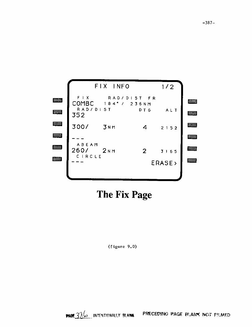
-387-
=ram
FIX INFO
FIX
COMBCRADI D I
352
RAD/Dt ST FR
184" / 236NM
ST DTG
3001 3NM 4
ABEAM
2601C I RC LE
I I i
2NM 2
112
ALT
2152
3165
ERASE>
mmm
mm_
The Fix Page
(figure 9.0)
II_IE_o INTENTI_NAtLY _t_ffiI_PRIECEDING PAGE B!,.AN_ NOT F_LMED


-389-
N
Nav Display Fix Example
(figure 9.1)
P,/t_E.__._. fNTENTr0NALLY BI_Am PRECEDING PAGE BLANK NOT FILMED


-391-
MODULE NAME:
FILE NAME:
PROCESS:
CALLED BY:
CALLING SEQUENCE:
FIX INFO
FIX?FOR
SLOW
CDUEXC
CALL FIX INFO
PURPOSE:
FIX INFO is the main FIX routine.
DESCRIPTION:
When a user has selected the CDU FIX page, the CDU
executive CDUEXC calls FIX INFO once per SLOW task cycle.
Fix information is represented in a FORTRAN structure
declared in the file FIXCOM. INC. This structure contains:
FIX(PG) .ADDR: AADCOM address of the fix
FIX(PG) .NAME: fix name
FIX(PG) .NAME LEN: number of chars in fix name
FIX(PG) .TYPE: fix type (nvd=l, wpt=2, apt=3)
FIX(PG) .BRG: mag bearing from fix to aircraft (deg)
FIX(PG) .CIRCLE: fix circle radius size (nm)
FIX(PG) .DIST: distance from fix to aircraft (nm)
FIX(PG) .LAT: fix latitude (deg)
FIX(PG) .LON: fix longitude (deg)
FIX(PG) .MAG: fix magnetic variation (deg)
FIX(PG) .SET: boolean set when a fix has been entered
FIX(PG) .RAD (I) .SET: conveys a radial has been entered
FIX(PG) .PAD(I) .INDEX: path segment number containing
intercept point (IP)
FIX(PG) .RAD(I).VAL: radial value (deg)
FIX(PG) .RAD(I) .IP LAT:
FIX(PG) .RAD(I).IP LON:
FIX(PG) .RAD(I).IP ALT:
FIX(PG) .RAD(I) .IP DIST:
FIX(PG) .RAD(I) .IP DTG:
radial IP latitude (deg)
radial IP longitude (deg)
radial IP programmed alt (ft)
distance from fix to IP (nm)
aircraft distance to go along
path to IP (nm)
where PG is the fix page number (I or 2) and I is the radial
number (i, 2, 3, or abeam = 4).
If an input has been made and a fix has not yet been
entered on the page, the entry must be either a fix at
LSKLI or a page change request using the NEXT or PREV CDU
panel keys. FIX INP is called if a fix was entered and
CH FIX PG is calTed to handle a page change. Any other
inputs will result in the output of an error message.
_Ixll_. __c_..) _luTF_T,qNAIIY BI_NI PR'ECEBING FAP__ BLANK NOT FILMEP

-392-
After any inputs are processed, POS INFO is called
to compute the distance and magnetic bearing from the
fix(es) to the current aircraft position. Next, if 2D
guidance is possible (GUID2D on), the aircraft distance
to go along the path to all existing radial intercept points
is computed by COMP IP DTG. FIX DISP is then called to set
the global variables in the global section DISNAV, needed
for displaying fix information on the ND.
Finally, CDU line outputs are performed. All output
lines are handled in this routine except for radial output
lines which are managed by calls to OUT RAD. A different
CDU line is output on each FIX INFO call. All actual CDU
output is handled through calls to FMTOUT.
Fixes are erased from the CDU and ND by pressing the
"ERASE>" key or by entering "DELETE" and pressing the fix
name line select key (LSKLI).
GLOBAL REFERENCES:
VARIABLES
ERCODE* GUID2D LAT LON PG PGINIT*
ARRAYS
BOXES DASHES ENTRY*
RECORD ARRAYS
FIX
FUNCTIONS AND SUBROUTINES
CDU SMALL CH FIX PG COMP IP DTG DEL FIX DEL IN FIX DISP
FIX--INP FMTOUT OTS$CVT L--TI--OTS$FLOAT OUT RAD POS I--NFO
-393-
MODULENAME:FILE NAME:PROCESS:CALLED BY:CALLING SEQUENCE:
OUT RADFIX.FORSLOWFIX INFOCALL OUT RAD(LINE, INDEX)
PURPOSE:This routine is called by the main fix routine
FIX INFO to output the parameters for the four radialsto the CDU.
DESCRIPTION:If a radial has not been entered, or in the case of the
computed abeam, dashes will be displayed. For enteredradials (i, 2, 3), if there is no intersection of a straightleg in the path, only the radial value will be displayed.When these radials intersect a straight leg, the radialvalue, distance between the fix and the intercept point,distance to go along the path from the aircraft's current
position to the intercept point, and the desired altitude
at the intercept point will be displayed. These parameters
are also displayed for the abeam radial if one has been
previously computed.
The input parameter LINE is the CDU line being
output and the INDEX is the radial index (1-4). All actual
CDU output is handled through calls to FMTOUT.
GLOBAL REFERENCES:
VARIABLES
PG
ARRAYS
DASHES
RECORD ARRAYS
FIX
FUNCTIONS AND SUBROUTINES
CDU SMALL FMTOUT OTS$CVT L TI
-394-
MODULENAME:FILE NAME:PROCESS:CALLED BY:CALLING SEQUENCE:
FIX INPFIX?FORSLOWFIX INFOCALL FIX INP(PASS)
PURPOSE:The purpose of this routine is to determine the type
of user input and call the appropriate input processingroutine.
DESCRIPTION:This routine is called by FIX INFO any time a user
input is detected. If an LSK has been pressed and thereis no data on the scratch pad, FUNC INP FIX is called.If a deletion is attempted by the us--er _data is "DELETE"),DEL_FIX is called. All other data inputs will be handled
by calling DATA INP FIX.
GLOBAL REFERENCES:
ARRAYS
ENTRY
FUNCTIONS AND SUBROUTINES
DATA INP FIX DEL FIX DEL IN FUNC INP FIX

-395-
MODULENA/ME:FILE NAME:PROCESS:CALLED BY:CALLING SEQUENCE:
FUNC INP FIXFIX.FORSLOWFIX INPCALL FUNC INP FIX (PASS)
PURPOSE:The purpose of this routine is to process LSK inputs
in which no data is involved.
DESCRIPTION:When an LSK has been pressed and there is no data on
the scratch pad, the following applies:
LSK-LI: If a fix name has been previously entered, it willbe written to the scratch pad; otherwise, a "NODATA" error message will be output.
LSK-L2,
LSK-L3,
LSK-L4:
If a fix radial exists at the LSK and an intercept
point was found, the latitude and longitude of the
intercept point will be written to the scratch pad.
If the fix radial does not have an intercept point,
a "NO DATA" message is displayed. If a radial has
not yet been entered, a "DEAD KEY ERROR" message
is output.
LSK-L5: If 2D guidance is available (GUID2D on), thenCOMP ABRAD is called to find the abeam radial.
If there is no abeam radial, the message "NO ABEAM
RADIAL" will be displayed. If 2D guidance is not
available, the "DEAD KEY ERROR" message is output.
LSK-L6: Circle data is expected. "NO DATA" will be
displayed if a fix has been previously entered and
"DEAD KEY ERROR" will be output otherwise.
LSK-R6: The fix is erased from the CDU and the ND. FIX INIT
is called to reset the fix data structure.
Pressing any of the remaining LSKs will result in a "DEAD
KEY ERROR" message.

-396-
GLOBAL REFERENCES:
VARIABLESERCODE* GUID2D PG
ARRAYSENTRY
RECORDARRAYSFIX
FUNCTIONSAND SUBROUTINESCH FIX PG COMPABRADFIX INIT FMTDEGFMTOUTSTRIPR

-397-
MODULENAME:FILE NAME:PROCESS:CALLED BY:CALLING SEQUENCE:
DATA INP FIXFIX.FOR --SLOWFIX INPCALL DATA INP FIX
PURPOSE:This routine handles fix data inputs.
DESCRIPTION:DATA INP FIX is called by FIX INP whenever an attempt
to input data--via the LSKs is made? The following listexplains what is expected for each LSK.
LSK-LI: Input should be a fix name. If the number ofcharacters is not 3, 4, or 5, a "BAD DATA FORMAT"message is output. LUNAVA is called to look upthe fix in AADCOM. If found, the .MAG, .ADDR,.NAME, .LAT, and .LON fields of the FIX structureare retrieved from AADCOM. The .TYPE is setaccording to the fix type (airport, navaid, orwaypoint). The .NAME LEN field is set to the numberof input characters and the .SET field is set. If
the fix is not found in A2dDCOM, a "NOT FOUND IN
MEMORY" error message is output.
LSK-L2,
LSK-L3,LSK-L4:
Radials are entered at these LSKs. If 2D guidance
is possible and the entry is a number between 0.0
and 360.0 , COMP RAD is called to find the intercept
point and compute all associated radial information.
LSK-L5: Data is not allowed for the abeam LSK.
DATA ENTRY" will be output.
"INVALID
LSK-L6: A circle whose radius must be between 1 and 99.9
can be entered at this LSK. The .CIRCLE field of
the fix data structure is set to the input value.
If the entry does not fall in this range, a "DATA
OUT OF RANGE" message is output.
LSK-R6: Data is not allowed for the "ERASE>" LSK. "INVALID
DATA ENTRY" will be output.
All other keys are dead keys. Also, if a fix has not yet
been entered, all keys except for LSKLI will be dead keys.
Also note that if any numerical entry cannot be successfully
converted from character to floating point format, a "BAD
DATA FORMAT" message will be output.

-398-
GLOBAL REFERENCES:
VARIABLES
ERCODE* FNAME GUID2D INDAT PG
ARRAYS
ENTRY*
RECORD ARRAYS
FIX*
FUNCTIONS AND SUBROUTINES
COMP RAD GET LONG GET REAL LUARP LUGRP LUNAVA OTS$CVT T F
-399-
MODULENAME:FILE NAME:PROCESS:CALLED BY:CALLING SEQUENCE:
DEL FIXFIX.FORSLOWFIX_INFO, FIX_INPCALL DEL FIX
PURPOSE:This routine handles "DELETE" fix inputs.
DESCRIPTION:FIX INP and FIX INFO call DEL FIX when a user has
entered "DELETE" as data. The following applies for thistype input:
LSK-LI: The fix page is reinitialized. The associated fixinformation drawn on the ND will also be erased.FIX INIT is called to reset the fix data structure.The CDU will be ready for a new fix to be entered.
LSK-L2,LSK-L3,LSK-L4:
The radial and its associated information isromoved from the CDU and ND and the appropriateradial fields of the fix data structure are reset.
LSK-L5: The fix circle is removed from the CDU and ND andthe .CIRCLE field of the fix data structure is setto zero.
Attempting to delete one of these parameters when it doesnot exist results in an "INVALID DELETE" error message. Anyother deletion attempt results in a "DEAD KEY ERROR" error.
GLOBAL REFERENCES:
VARIABLESERCODE* PG
ARRAYSENTRY
RECORDARRAYSFIX
FUNCTIONS AND SUBROUTINESFIX INIT

-400-
MODULE NAME:
FILE NAME:
PROCESS:
CALLED BY:
CALLING SEQUENCE:
CH FIX PG
FIX. FOR
SLOW
FIX INFO
CALL CH FIX PG(PG)
PURPOSE:
This routine handles page changes between the two fix
pages.
DESCRIPTION:
When the user has pressed the PREV or NEXT CDU panel
buttons, FIX_INFO calls CH_FIX_PG to set the current page
variable PG so that the inactive fix page becomes active.
GLOBAL REFERENCES:
FUNCTIONS AND SUBROUTINES
FMTOUT
-401-
MODULENAME:FILE NAME:PROCESS:CALLED BY:CALLING SEQUENCE:
FIX INITFIX?FORSLOWFUNC_INP_FIX, DEL_FIXCALL FIX INIT
PURPOSE:This routine reinitializes those variables necessary
to erase a fix page.
DESCRIPTION:When a user wishes to erase a fix from the CDU and the
ND, FUNC INP FIX and DEL FIX calls FIX INIT to reset
the fields of the fix structure so that the fix will no
longer be displayed.
GLOBAL REFERENCES:
VARIABLES
PG
RECORD ARRAYS
FIX*

-402-
MODULENAME:FILE NAME:PROCESS:CALLED BY:CALLING SEQUENCE:
COMPABRADFIX.FORSLOWFUNC INP FIX
PURPOSE:This routine attempts to find the shortest abeam radial
between a fix and a straight leg segment of the active path.
DESCRIPTION:When a user presses the "abeam" line select key (LSKL5)
for a given fix, FUNC INP FIX calls this routine to searchthe remainder of the active path for a straight leg segmentin which a radial drawn from the fix to the segmentintersects perpendicularly.
FIND LEG AB is called for each straight leg segment toperform tee a_tual computations that determine whether thesegment contains an abeam radial. If the aircraft's positionis currently on a straight leg and the cross track error XTKis less than 200 feet, the unflown portion of that segmentis also considered. A segment is considered to be astraight leg if either of its waypoint DMA fields are zero(i.e. WPT ACT(J).DMA = 0 or WPT ACT(J+I).DMA = 0, where J+lis the 'TO' waypoint of the segment). Once all of the abeamshave been found, FMIN is called to determine which abeamhas the shortest distance between the fix and the interceptpoint. It is this abeam that will be displayed on the CDU
and ND. Before exiting COMP ABRAD calls AB IP LL to
compute the intercept point latitude and longitude and
COMP IP DTG to compute the distance to go along the path
to tee Yntercept point. If this distance is greater than
zero meaning the intercept point has not been already
passed, the desired altitude at the intercept point is
also computed.
If no abeams exist, the error message "NO ABEAM
RADIAL" will be output to the CDU.
GLOBAL REFERENCES:
VARIABLES
ACTCNT DTOGO ERCODE* LAT LON PG TOWPT XTK
RECORD ARRAYS
FIX* WPT ACT
FUNCTIONS AND SUBROUTINES
AB IP LL COMP IP DTG FIND LEG AB FMIN MTH$TAND POS INFO
UNITVEC

-403-
MODULENAME:FILE NAME:PROCESS:CALLED BY:CALLING SEQUENCE:
FIND LEG ABFIX.FORSLOWCOMP_ABRAD,COMP_RADCALL FIND LEG AB(FR VEC, VEC, FLAT,
FLON, FRLAT, FRLON,PTR, DIST)
PURPOSE:The purpose of this routine is to find out if an
abeam radial exists for a given straight leg path segment.
DESCRIPTION:
FIND LEG AB calls COMP ANG to compute two angles whose
values tell whether or not a segment contains an abeam
radial for a fix. The first angle is the one which
contains the leg's FROM and TO waypoints and the fix
location. The vertex of this angle is the TO waypoint
location. The second angle contains the same points except
that the vertex is the FROM waypoint. If these two angles
are both acute angles, an abeam radial must exist for the
leg. If an abeam is found, the distance between the fix and
the intercept point is computed. This distance must be
greater than 100 feet or the abeam will be rejected.
GLOBAL REFERENCES:
RECORD ARRAYS
WPT ACT
FUNCTIONS AND SUBROUTINES
COMP ANG FIX ERAD MTH$ATAN2 VDP
-404-
MODULE NAME:
FILE NAME:
PROCESS:
CALLED BY:
CALLING SEQUENCE:
UNITVEC
FIX.FOR
SLOW
COMPABRAD, COMP RAD
CALL UNITVEC(ULAT, ULON, UVEC)
PURPOSE:
This routine computes a unit vector (UVEC) from the
earth's center to a position given by its latitude (ULAT)
and longitude (ULON)
DESCRIPTION:
This routine is called when a unit vector from the
earth's center to the given latitude and longitude is needed
in COMP ABRAD and COMP RAD computations.
GLOBAL REFERENCES:
FUNCTIONS AND SUBROUTINES
MTH$COSD MTH$SIND

-405-
MODULENAME:FILE NAME:PROCESS:CALLED BY:CALLING SEQUENCE:
FMINFIX.FORSLOWCOMPABRAD, COMPRADCALL FMIN(X, CNT)
PURPOSE:This routine searches the array X for a minimum value
greater than zero and returns its position CNT in the array.
DESCRIPTION:A simple loop is used to find the minimum value greater
than zero in the array. If all elements are less than zero,CNT is returned as zero.
GLOBAL REFERENCES:none

-406-
MODULENAME:FILE NAME:PROCESS:CALLED BY:CALLING SEQUENCE:
FIX ERADFIX.FORSLOWFIND LEGAB, COMPRADCALL FIX ERAD(ALTI, RADI, LATFT, LONFT)
PURPOSE:This routine computes the earth radius for a given
position.
DESCRIPTION:East/west and north/south values are computed for a
given position and are then used to compute a local "feetper degree" value for latitude and longitude at thatposition.
GLOBAL REFERENCES:
VARIABLESLAT
FUNCTIONS AND SUBROUTINESMTH$COSDMTH$SIND

-407-
MODULENAME:FILE NAME:PROCESS:CALLED BY:CALLING SEQUENCE:
AB IP LLFIX.FORSLOWCOMPABRAD, COMPRADCALL AB_IP_LL (VECT, PTR, TMP_LAT, TMP LON)
PURPOSE:The purpose of this routine is to compute the latitude
and longitude of an intercept point between an abeam radialand a given path segment.
DESCRIPTION:Given the abeam input vector (VECT) and the normal
vector WPT_ACT(PTR).NMV, the intercept point latitude(TMP_LAT) and longitude (TMP_LON) are computed usingvector algebra.
GLOBAL REFERENCES:
RECORDARRAYSWPTACT
FUNCTIONS AND SUBROUTINESMTH$ASIND MTH$COSDVDP
-408-
MODULE NAME:
FILE NAME:
PROCESS:
CALLED BY:
CALLING SEQUENCE:
COMP RAD
FIX.FOR
SLOW
DATA INP FIX
CALL--COMP RAD(VAL, INDEX)
PURPOSE:This routine is called to find an intercept point
between a radial and a straight leg segment of the unflown
portion of the active path.
DESCRIPTION:
A user is able to enter up to 3 radials (other than
the abeam radial) per fix. These radials have values
between 0.0 and 360.0 degrees. Each time a radial is
entered, this routine is called by DATA INP FIX to see if
the radial intersects a straight leg seg--men[ of the unflown
active path. Passed as inputs are the radial value in
degrees (VAL) and the radial index (i, 2, or 3) INDEX.If the current path leg is a straight segment, COMP RAD
first checks to see if there is an intercept point between
the aircraft's current position and the 'TO' waypoint.
FIND LEG RAD is called to actually do the computations
needed t_ determine if the correct geometry for intersection
exists. The remaining straight legs are then searched.
Once all intercept points have been found, FMIN is called to
determine which radial has the shortest distance from the
fix to the intercept point. This distance, however, must
be greater than 100 feet or it will not be considered.If no intercept points were found, only the radial
value will be displayed on the CDU. The radial will still
be drawn on the ND.
If a minimal distance intercepting radial
is found, the intercept point latitude, longitude, and
altitude are computed. Also, COMP_IP_DTG is called to
compute the aircraft's distance to go along the path to the
intercept point. Displayed on the CDU radial line is the
radial value, distance in nautical miles from the fix to
the intercept point, aircraft distance to go in nautical
miles to the intercept point, and the aircraft's desired
altitude in feet at the intercept point.
GLOBAL REFERENCES:
VARIABLES
ACTCNT DTOGO LAT LON PG TOWPT XTK
RECORD ARRAYS
FIX* WPT ACT
FUNCTIONS AND SUBROUTINES
AB IP LL COMP IP DTG FIND LEG AB FIND LEG_RAD FIX_ERAD
FMIN MTH$COSD MTH$SIND MTH$TAND UNITVEC

-409-
MODULENAME:FILE NAME:PROCESS:CALLED BY:CALLING SEQUENCE:
FIND LEG PADFIX.FORSLOWCOMPRADCALL FIND_LEG_RAD(FRLAT, FRLON, FLAT,
FLON, TOLAT, TOLON,PTOPD, VAL, PTR, DIST)
PURPOSE:The purpose of this routine is to find an intercept
point between a fix radial and a straight leg segment.
DESCRIPTION:Given input latitudes and longitudes for the 'TO' and
'FROM' waypoints of the path segment and the fix, FIND LEG RADis able to determine whether or not an intercept point-- --exists. It does this by computing two bearings: one fromthe fix to the FROMwaypoint of the segment and the otherfrom the fix to the 'TO' waypoint. If the radial value liesbetween these two bearings, an intercept point must existand the distance between the fix and the intercept pointwill be computed.
GLOBAL REFERENCES:
VARIABLESPG
RECORDARRAYSFIX
FUNCTIONS AND SUBROUTINESCOMP_ANGFANG GRID MTH$ATAND2MTH$COSDMTH$SIND MTH$SQRT

-410-
MODULEN;_4E:FILE N_ME:PROCESS:CALLED BY:CALLING SEQUENCE:
F ANG(X, Y, ANG)FIX.FORSLOWFIND LEG RAD
PURPOSE:This routine is called to find the angle between two
given bearings that share a common vertex.
DESCRIPTION:The bearing inputs X and Y have values between -180.0
and 180.0 degrees. The angle between the bearings will bereturned in ANG as a value between 0.0 and 360.0 degrees.

-411-
MODULENAME:FILE NAME:PROCESS:CALLED BY:CALLING SEQUENCE:
COMPANGFIX.FORSLOWFIND LEG AB, FIND LEG RADCALL COMPANG(LTI, LNI, LT2, LN2, LT3,
LN3, ANG)
PURPOSE:This routine computes the angle between a vertex
point and two other points.
DESCRIPTION:The latitudes and longitudes of three points are passed
in as parameters. The second lat/lon pair is the vertex.The computation is a matter of simple geometry. The angleis stored in ANG and will have value between 0.0 and 360.0degrees.
GLOBAL REFERENCES:
FUNCTIONS AND SUBROUTINESGRID MTH$ATAND2

-412-
MODULENAME:FILE NAME:PROCESS:CALLED BY:CALLING SEQUENCE:
POS INFOFIX.FORSLOWFIX INFO, COMPABRADCALL FIX INFO(LTI, LNI, LT2, LN2, DIST,
BRG)
PURPOSE:The purpose of this routine is to compute the magnetic
bearing (degrees) and distance (feet) between two points.
DESCRIPTION:POS INFO is called whenever bearing and distance are
needed between two points. It uses the latitudes andlongitudes of the two points to perform the computations.The bearing will be returned as a value between 0.0 and360.0 degrees.
GLOBAL REFERENCES:
VARIABLESPG
RECORDARRAYSFIX
FUNCTIONS AND SUBROUTINESGRID MTH$ATAND2MTH$SQRT

-413-
MODULENAME:FILE NAME:PROCESS:CALLED BY:CALLING SEQUENCE:
COMPIP DTGFIX.FORSLOWFIX INFO, COMPABRAD, COMPRADCALL COMPIP DTG(PG, INDEX7 DTGO)
PURPOSE:This routine is called to compute the distance along
the path from the aircraft's current position to a radial'sintercept point on the path.
DESCRIPTION:
COMP IP DTG is called every time FIX INFO is called
to compute the distance to the intercept point for the
active fix (PG) and the given radial index (INDEX). It
sums I) the distance from the current position to the 'TO'
waypoint, 2) the distances of the path legs up to the
waypoint just before the intercept point, and 3) the
distance from that waypoint to the intercept point. If
the intercept point has already been passed, there is
no computation to perform and only the radial value will
be displayed. In this case DTGO is passed back as zero.COMP ABRAD and COMP RAD also call this routine. If
the distance returned is zero, these routines do not
attempt to compute the desired aircraft altitude at the
intercept point.
GLOBAL REFERENCES:
VARIABLES
DTOGO LAT LON TOWPT
RECORD ARRAYS
FIX* WPT ACT
FUNCTIONS AND SUBROUTINES
GRID MTH$SQRT

-414-
MODULENAME:FILE NAME:PROCESS:CALLED BY:CALLING SEQUENCE:
FIX DISPFIX.FORSLOWFIX INFOCALL FIX DISP
PURPOSE:This routine sets the parameters used by the displays
computer to display fix information on the NavigationDisplay.
DESCRIPTION:FIX INFO calls this routine every time the executive
calls FIX INFO. The global integer array FIXWRD(2) has bitpatterns that are set by FIX DISP. FIXWRD is used by thedisplays computer to graphically represent the fix(es) andradials. FIXWRD(1) is used for the first fix and FIXWRD(2)is used for the second page. The bit patterns for eachword are:
bit 0:bit I:bit 2:bit 3:bit 4 :bit 12 :bit 13 :bit 14:
set if a fix has been enteredset if first radial has been enteredset if second radial has been enteredset if third radial has been enteredset if abeam has been computedset if fix is a navaidset if fix is a waypointset if fix is an airport
If the conditions for setting a bit do not exist it remainscleared. Also set for use in the displays computer and NDare the following global variables:
FIXADD: address of fix in AADCOMFIXCIR: fix circle radiusFIXRAD(I - 4): radial values
GLOBAL REFERENCES:
VARIABLESFIXADD* FIXCIR* FIXRAD* FIXWRD*
RECORDARRAYSFIX
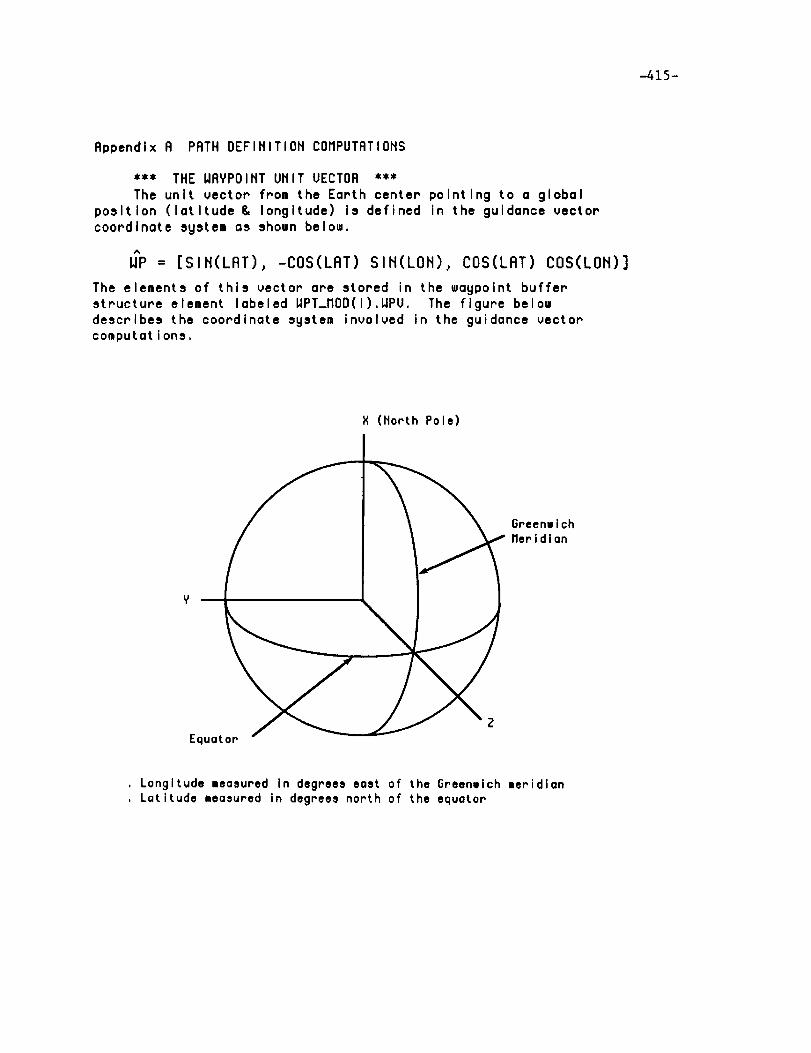
-415-
Appendix A PATH DEFINITION COMPUTATIONS
*** THE WAYPOINT UNIT VECTOR ***
The unit vector from the Earth center pointing to a global
posltlon (latltude & longltude) Is defined in the guldance vector
coordlnate system as shown below.
W_P = [SIN(LAT), -COS(LAT) SIN(LON), COS(LAT) COS(LON)]
The elements of this vector are stored in the waypolnt buffer
structure element labeled WPT_MOD(1).WPV. The figure below
descrlbes the coordlnate system Involved in the guidance vector
computat ions.
X (North Pole)
Equator
Greenwlch
Meridian
. Longitude measured in degrees east of the Greenwich meridian
. Latitude measured in degrees north of the equator

-416-
*** THE NORMAl. UNIT VECTOR ***
The normal unlt vector Is calculated as follows.
.-% .,% .,,.._(i) = WP(i-I) x WP(i); NM(i) = / I 'M(i)I
The elements of these vectors are stored In the waypolnt buffer
element labeled WPT_MOO(1).NMU. The figure below deplcts therelatlonshlp between the normal unlt vector and its associated
waypolnt unlt vector palr.
..%WP(i) W"P(i+I)
NM(i+I )
*** TURN ANGLE (TA) BETWEEN WAYPOINTS ***
The normal unit vector and the waypoint unit vectors are used
to compute the track angle change between waypoints by using the
fol lowing equat ions...%
SIN_TA = -I_ (i) x NM(i+I) . W'_(i).-% /%
COS_TA = NM(i) . NM(i+I)
TA = ARCTAN2(SIN_TA, COS_TA)
The turn angle at each waypolnt, except the first and last on the
fllght plan or DMA turn waypolnts, is stored in the waypointstructure under the label WPT_MOD(i).TR.
*** RADIUS OF TURN ***
The following llst shows the three ways the turn radlus at a
waypolnt may be deflned. They are llsted in the order of hlghest
priority.
Asslgned dlrectly from the CDU.
Default from system database when waypoint is part of a definedroute functlon.
When a ground speed Is deflned at the waypolnt, the equatlonR = GS ** 2 / (G * TAN_15_DEG).
When the waypolnt altltude is assigned, and greater than 15000
feet, the radlus is set to 50000 feet.Radius is set to 15000 feet.
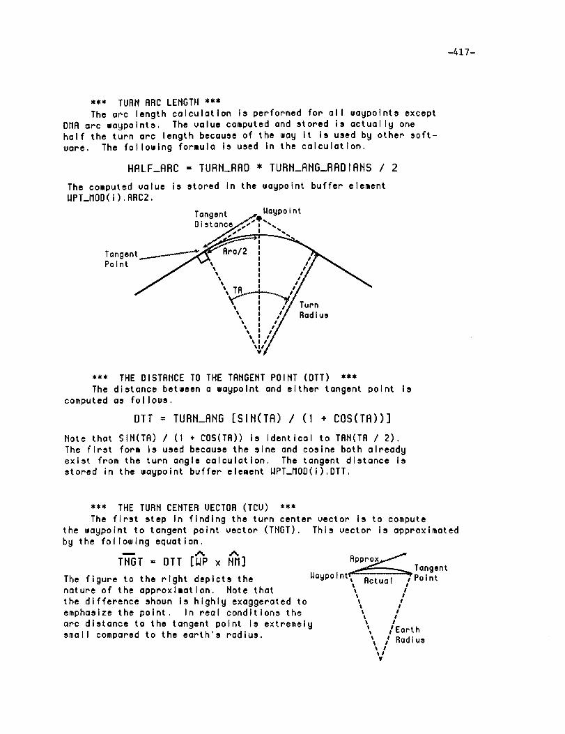
-417-
*** TURNARCLENGTH ***
The arc length calculatlon Is performed for all waypolnts except
DMA arc waypolnts, The value computed and stored is actually onehalf the turn arc length because of the way It Is used by other soft-
ware, The following formula Is used in the calculatlon.
HALF_ARC = TURN_RAD * TURN_ANG_RADIANS / 2
The computed value is stored In the waypolnt buffer elementWPT_MOD(i),ARC2,
Tangent _.slWaypoint
Distancee1_1-f'T'-..
,rc , I
\ I // Turn\ : H Rod\ i //\, i,,Y
*** THE DISTANCE TO THE TANGENT POINT (DTT) ***
The distance between a waypolnt and either tangent point iscomputed as follows,
DTT = TURN_ANG [SIN(TA) / (I + COS(TA))]
Note that SIN(TA) I (I + COS(TA)) is identical to TAN(TA 1 2),
The flrst form is used because the sine and cosine both already
exist from the turn angle calculatlon. The tangent distance is
stored in the waypoint buffer element WPT_MOD(1),DTT,
the waypoint to tangent point vector (TNGT).
by the following equatlon._.. ..... ..%TNGT = DTT [WP x NM]
The flgure to the right depicts thenature of the approxlmatlon, Note that
the difference shown is highly exaggerated toemphasize the polnt. In real conditions the
arc dlstance to the tangent point is extremelysmall compared to the earth's radius.
*** THE TURH CENTER VECTOR (TCV) ***
The first step In flndlng the turn center vector Is to computeThis vector is approximated
TangentWaypolnt_ Actual oPoint
l !t Il Il It Il !l Il I
l /EarthI / RadiusI
I Itl¥

-418-
Next the vector fom the earth's center to the tangent point (TP) Is
computed as follows.
TP = ERRTH_RAD WP + TNGT
The turn center vector calculations proceed as shown below. Note
that the "+/-" shown means add in a left turn and subract in a
right turn._.. =.., A'% ,'% ---- ,--,,TCU = TP +/- (TURN_RRD NM); TCU = TCU / ITCVI
The turn center vector Is saved as WPT_MOD(i).TCU
*** THE DISTANCE BETWEEN WAYPOINTS (PPD) ***
The distance between waypolnts, "point to point" distance, is
found by computlng the angle (radlans) between successlve wagpointThe computed value is savedvectors. The ecluatlons are shown below.
as WPT_MOD( I).PPD_
SIN_t = IWP(i-I) x WP(i)I
PPD = EARTH_RAD ARCSIN(SIN_$)
Waypoint _Waypolnt
% lI
I II II II I% !
l /Eartht
I / Radius%% !IIV
*** CENTER OF TURN LEG DISTANCE (CCD) ***
The along path distance between waypolnts, turn center to turn
center, Is computed from the polnt to point distance by adjustlng
each end of the polnt to polnt line. The adjustment Is performedas follows.
CCD(i) = PPD(i) - DTT(i) + ARC(i) - DTT(i-I) + ARC(i-I)
Note that no adjustment is performed for leg ends havlng a OMA
turn waypolnt slnce no DTT or ARC dlstances are deflned. The
resultlng path dlstance Is saved as WPT_MOD(1).CCD.
., ................................................ PPO ................................ ,.
Waypoint _-_
Turn Cente_
L___ur Wayp°Int
n Center

-419-
*** THE FLIGHT PATH ANGLE (FPA) ***
The flight path gradient between successive waypoints Is
approximated from the along path distance between waypoints and
the change In asslgned altltudes. The computed value is actually
the tangent of the fllght path angle, however it wlll approximate
the desired number for the small flight path angles typically on
the fllght plan.
FPA_RADIANS = (ALT(i) - ALT(i-I)) I CCD(i)
The value Is converted to degrees and stored in WPT_MOD(i).FPA.
*** THE PATH LEG TIME ***
The tlme required to fly a leg of the fllght plan is computed
when ground speeds (GS) are deflned for both leg end waypoints.
TIME(i) = 2 CCD(i) / (GS(i) + GS(i-I))
Note that the ground speeds must be converted to feet per secondbefore use (stored as knots) since the path dlstance (CCD) is
deflned In feet. The resultlng value of leg time is saved inWPT_MOD( i).TIME.
*** DMA ARC COMPUTATIONS ***
The DMA arc reference waypolnt posltlon, projection bearing and
turn angle are predeflned In the navlgatlon database. The
position of the projected waypolnt and along path distance arecomputed as follows.
LAT = LAT_REF + TURN_RAD COS(BRNG) / DLATFT
LON = LON_REF + TURN_RAD SIN(BRNG) / DLONFT
CCD = TURN_ANGLE_RADIANS TURN_RAD
Note that DLATFT and DLONFT are the number of degrees per foot in
latltude and longltude respectlvely, defined for the locallty ofthe current turn center.
ProjectedInbound / _ Outbound
Waypoi nt/.... Turn //_aypo,nt
BearingS. _"_v Reference
gaypoint

i
REPORT DOCUMENTATION PAGE FormApprovedOM8,yD.oTo_,aa
Public repOrtmg burden for this ,:ollection of information *s e,,tlmated to avecaqe 1 hour per re_oon_e, including the time for reviewing instructions. _arching existing data sOclrces.gathering and maintaining lhe data needed, and completmg and reviewing the collection of information. ¢_en¢l comments regarding this burden e_timate or any other aw_'<t of th s
collectiOn Of information, including sugg¢_tio_ for reducing thl_ burden to Washington Headquarters Services. DirectOrateTo." Information Operations and Reports. 1215 JeffersonDaws Highway. Sucre 1204. Arhnglon. VA 22202-4 |0;_. al_l to the. Offl, e Of Mana_Jemq.n! .ind Budget. Paperwork Reduction Project (0/04-0 ! 08). Washington. DC 2050].
1. AGENCY USE ONLY (Leave blank) 2. REPORT DATE I 3. REPORT TYPE AND DATES COVERED
January 1992 I Contractor Report
4. TITLEANDSUBTITLEAdvanced Transport Operating System s. FUNOINGNUMBERS
(ATOPS) Control Display Unit Software Description
6. AUTHOR(S)
Christopher J. S1ominski William J. HeaphyMark A. Parks
Kelly R. Debure
7. PERFORMING ORGANIZATION NAME(S) AND AOORESS(ES)
Computer Sciences Corporation3217 N. Armistead Avenue
Hampton, Virginia 23666-1379
g. SPONSORING/MONITORING AGENCY NAME(S) AND ADORESS(ES)
National Aeronautics and Space Administration
Langley Research CenterHampton, Virginia 23665-5225
C NAS1-19038
WU 505-64-13-11
8. PERFORMING ORGANIZATIONREPORT NUMBER
10. SPONSORING / MONITORINGAGENCY REPORT NUMBER
NASA CR-189606
11. SUPPLEMENTARY NOTES
Langley Technical Monitor:
IZa.DISTRIBUTION/AVAILABILITYSTATEMENT
Unclassified - Unlimited
Subject Category 06
Dr. James R. Schiess (COTR)Robert A. Kudlinski
12b. DISTRIBUTION CODE
j,
_. ABSTRACT (Maximum 200 words)
his document describes the software created for the Lear-Siegler Control Display
Units (CDUs) used for the Advanced Transport Operating Systems (ATOPS) project on
the Transport Systems Research Vehicle (TSRV). The software delivery of April1991, known as the "baseline system", is the one described in this document.
Throughout this publication, module descriptions are presented in a standardized
format which contains module purpose, calling sequence, detailed description andglobal references. The global reference section incl_udes subroutines, functions
and common variables referenced by a particular module.
The system described supports the Research Flight Deck (RFD) of the TSRV. The RFD
contains two Lear-Siegler CDUs, one for the pilot and copilot, which are used for
flight management purposes. Operations performed with the CDU affects the aircraft'
guidance, navigation, and display software.
14. SUBJECT TERMS Aircraft Navigation SystemsFlight Management Systems _lass Cockpit
Control Display Unit
Flight Planning
17. SECURITY CLASSIFICATIONOF REPORT
Unclassified
"NSN 7540-01-280-5500
F1ight Managementbompu _er
Area Navigation Software
Electronic Flight Instrumentation System
18. SECURITY CLASSIFICATION 19. SECURITY CLASSIFICATIONOF THIS PAGE OF ABSTRACT
Uncl assi fied Uncl ass ified
15. NUMBER OF PAGES
42O
1,. P_(_ CODE
20. LIMITATION OF ABS TRACT
Standard Form 29B (Rev 2-89)Pr_,crlbed by ANSI $td Z39-18298-102