Embed Size (px)
Citation preview

fADVANCED TECHNOLOGY COMPOSITE
AIRCRAFT STRUCTURESMONTHLY TECHNICAL PROGRESS REPORT NO. 25
FOR PERIOD MAY 1 - MAY 31, 1991
I_B_,U_ED FOR
NATIONAL AEFIONAUTICS ,_ID 8PACE ADlUa81rRATIONLANGLEY RESEAN_ CENTF.R
HAIlMTOM, VlFIGHA 23065.622S
UNDER CONTRACT NASl-lmm
JUNE 14,1991
(NASA-CR-190420) ADVANCE_
TECHNOLOGY COMPOSITE AIRCRAFT
STRUCTURES Monthly Technica|
Progress Peport No. 25, 1-31 May
1991 (_oein9 Commercial Airplane
Co.) 113 pG3/O5
?
fP_
i
N93-29498
Unclas
0175718
https://ntrs.nasa.gov/search.jsp?R=19930020309 2020-04-09T00:46:35+00:00Z

DISTRISUTION LIST - _ NJt.q1-_.8889
A'I'_J_ MO1_LT_Y TE_I_r3:CJLT._ 1?1_3G_:_,SS REIF_J_
I-MR.JOSEPH W. OWENS, NASA CONTRACT ADMINISTBJTOR M/S 126
8-MR.WILLIAM T. FREEMAN, TCHNICAL KEPRSENTATIVE NASA M/S-241
I-MR.JOHN SAMOS NEW TECHNOLOGY REPRESENTATIVE M/S-139A
I-D. COURTNEY, AFPRD M/S 3C-84
I-T. GUTOWSKI, MASSACHUSETTS INSTITUTE OF TECHNOLOGY
I-J.T. QUINLIVAN M/S 9R-62
I-R.W.JOHNSON M/S 3K-65
1-P.J. SMITH M/S 3K-65
1-L.B. ILCEWICZ M/S 3K-65
I-T.H. WALKER M/S 3K-65
I-M.A. APELES M/S 3K-65
I-D.R. SEEMAN M/S 6P-78
I-D.E. HASTINGS M/S 76-67
I-D.H. GRAND_. M/S 3K-65
I-K.S. WILLDKN M/S 57-09
I-M. MORRIS M/S 3K-65
I-K.H. SCHREIBER M/S 9R-62
1-D.L. GRANDE M/S 3T-CH
1-P.S. SAWC.HUK M/S 3T-CH
1-D.P. MOONEY M/S 9R-62
1-C.X. GUNTHER M/S P30-31
1-R. E. HORTON M/S 3T-CH
1-G.G. CASSATT M/S K25-41
1-K. VENTERS M/S 3T-AX
1-B.L. MILLER M/S 6X-03
1-J. McCARTY
1-W.B. AVERY M/S 82-32
1-D. ARNOLD M/S 4H-98
1-K. MACKEY M/S 9R-64
1-3. METSCHRN M/S 3K-65
P
DISTR.13_TION LIST - ATC_ NAS1-18889
ATCJ_ M01_TRLY _IC_L PROGRESS _ORT {cont.)
I-P. HARRADINE/M. SPENCER M/S 6R-MJ
I-B. COX-ROCKWELL INTL. SCIENCE CENTER
1-J. LAAKSO M/S 82-97
1-S. JOHNSTON M/S 7L-23
I-DR. RODERIC _S-UNI%_.RSITY OF IOWA
I-DR. J. AWERBUCH AND DR. A. WANG-DREXEL UNIVERSITY
1-DR. W.D. BASCOM-UNIVERSITY OF UTAH
I-M. KLOTZCHE-DOUGLAS AIRCRAFT CO.
1-J. SUAREZ-GRUP_4AN AIRCRAFT SYSTEMS
1-A. JACKSON-LOCKHEED AERONAUTICAL SYSTEMS CO.
1-R. B. DEO-NORTHROP CORP.
I-S.P. GARBO-SIKORSKY AIRCRAFT DIV.
1-DR. K.Y. LIN-UNIVERSITY OF WASHINGTON
1-DR. J. SEFERIS-UNIVERSITY OF WASHINGTON
1-DR. M.E. TUTTLE-UNIVERSITY OF WASHINGTON
1-OR. FU-KUO CHANG-STANFORD UNIVERSITY
1-OR. T. KENNEDY-OREGON STATE UNIVERSITY
1-DRS. P. LAGACE AND M. GRAVES-M.I.T.
1-C. GRANT-HERCULES AFROSPACE CO.
I-R. HOLTHE-ICI FIBERITE
I-B. COXON- INTEC
1-R. NEFF-WRIGHT PATTERSON
1-J. SODERQUIST-FAA
1-R. HOLZWORTH-WRIGHT PATTERSON
1-M. FEDRO M/S P30-30
1-ATCAS TEAM GROUP FILE
DIRECT QUESTIONS ON DISTRIBUTIC_ TO : MARGE APELES
393-9631 M/S 3K-65
65 COPIESh
q

ADVANCED TECHNOLOGY COMPOSITEAIRCRAFT STRUCTURES
MONTHLY TECHNICAL PROGRESS REPORTNO. 25
FOR PERIODMAY 1 - MAY 31
1991
PREPAREDFOR
NATIONAL AERONAUTICS AND SPACE ADMINISTRATIONLANGLEY RESEARCH CENTER
HAMPTON, VIRGINIA 23665-5225
UNDER CONTRACT NAS1-18889
Prepared
JUNE 14, 1991
b and
pal Investi_tor i _c_ral Mechanics
Approved by: _
R.W. JohnsonProgram Manager
BOEINGCOMMERCIALAIRPLANEGROUPTECHNOLOGYAND PRODUCTDEVELOPMENT
P.O. Box3707Seattle.Washington98124-2207
I OIW lot gamrll mlemm June 14,19LI.

-- ¢l
(
TABLE OF CONTENTS
1.0 .SUMMARY
2.0 INTRODUCTION
3.0 PROGRAM PERSONNEL
4.0 PROGRAM STATUS AND PLANS
4.1 CROWN
4.2
4.3
4.4
4.5
4.6
APPENDIX A
APPENDIX B
APPENDIX C
APPENDIX D
APPENDIX E
APPENDIX F
APPENDIX G
APPENDIX H
PANELS
4.1.1 Design Concepts4.1.2 Manufacturing Technology4.1.3 SupportingTechnology4.1.4 Mechanical Tests
KEEL PANELS
4.2.1 Design Concepts4.2.2 Manufacturing Technology4.2.3 Supporting Technology4.2.4 Mechanical Tests
SIDE PANELS
FRAMES AND ATTACHMENT DETAILS
4.4.1 ManufacturingTechnology4.4.2 Supporting Technology4.4.3 Mechanical Tests
FULL BARREL STUDIES
DESIGN COST MODEL
4.6.14.6.24.6.3
TheoreUcal Framework
Design ConstraintsSo,qware DevelopmeqtDesign Fam;ly Pictorials
Keel Design D1 and D2 IntercostalDrawing
Keel Design D1 Cargo Floor Frame Drawing
Keel Design D2 Frame Detags Drawing
Keel Design D2 Cargo Floor Details Drawing
Keel Design C1 Cargo Floor Details Drawing
PictodaJof Assembly of Keel Designs Dla and DlbD
1
3
6
7
7
11131618
19
19222327
28
28
283132
33
33
383839
Review Draft of: "NonlinearProperties of Metallic CellularMaterials With a Negative Poisson'sRatio"
¢

1.0 SUMMARY
This Twenty-fifth Technical Monthly Progress Report describes work performed during
May 1991 on NAS1-18889 *Advanced Technology Composite Aircraft Structure"
(ATCAS). The ATCAS "Concepts Assessment Review" was held in Seattle on May 15
and 16. Based on Phase A progress to date and plans for future ATCAS work, NASA
decided to proceed with Phase B.
Cruwn. Local crown panel optimization of a Family C concept has occurred over the
last nine months. The final crown design was projected to have cost and weight savings
(relative to 1995 aluminum technology) of 18% and 45%, respectively. These savings
are dose to those quoted as ACT program goals.
The three main tasks supporting local optimization were each found to affect cost and
weight. First, the enhanced tensile fracture performance of tow placed laminates was
realized while collecting a material's database. This lead to lower cost and weight.
Second, design variables were selected with the help of optimization software to
minimize cost and weight. As discussed in previous months, stringer spacing was found
to be the most significant variable affecting cosL This was found to relate to the effect of
stinger spacing on numerous manufacturing cost centers. The third task supporting
local optimization, fabrication trials, were performed to demonstrate innovative
processes which attack cost centers. This final activity continues to evaluate possible
changes in crow,_ panel manufacturing plans with a goP.Jto further reduce costs.
A soft tooling trial was performed, yielding a curved panel with cocured h_t sVingers and
cobonded frames. The trial variables included stringer mandrel type and edge trim. The
panel will be inspected for defects and measured for warpage in June. Fabrication of
crown manufacturing and test verification panels at Hercules remains behind schedule
due to limited machine availability and delays in subcontract procurement.
The progressive damage modeling effort being conducted at Stanford University w_s
reviewed, and a plan for the remainder of the contract was developed. This plan
includes improvements to the plane-stress model to address multiple material zones,
and verification of the model with several of the large crown test panels. Continued
development of verification test plans resulted in elimination of two of the four fiat post-
buckling panels, since their response was not representative of the actual crown design.
Keel. Design work for global evaluation of keel panels continued with the release of
several drawings. These included intercestals, and cargo floor frame details for Family
D designs. Cargo floor details for the first Family C design were also completed. The
design drivers for Family D and C keel concepts were identified during sizing exercises,
indicating the need for materials and designs with balanced performance capabilities for
compression, hoop tension, and shear in keel applications.
Work continued in developing manufacturing plans for keel panel designs. An
installation plan was completed for the first Family D keel panel. A detailed pictorial of
25-1PRIEC.J_f,_'R PAOli BI_ANIK NOT
O
im
this plan was included in Appendix G. Recurring and nonrecurring laborestimates wereobtained for all cost components of the first Family D design with the excepUon of panelinstailaUon. Results obtained to date will be reviewed by the ATCAS DBT beforedocumenlJngin a monthly report.
Work was started to initiate a second subconVact to study insitu foam processing ofsandwich panels with the Sundsti'and Corporation. This second study will consist offabricaUon Vials that address critical keel manufacturing issues such as thick sandwichfacesheets, varying core thickness, and tapered skin thickness,
Results were presented for matY_ spliffing in unidirectional spedmens of tough andbritlJe matrix composites, indicatinga greater resistance to splittingin the former. Sometemperature differences in the matrix splitting resistance of toughened materials werenoted for specimens subjected to fatigue cycles. Matrix splittingis generally consid._redan attribute for tension damage tolerance of multidirectional laminates. Since hooptension damage tolerance is still a design driver for the aft end of the keel panel, thetensile fracture of toughened systems considered for keel applications will need to bestudied. Work at the Universityof Utah (Bascom ACT contract) will address the need forunderstanding the competing failure mechanisms of tough and brittle tow-placedlaminates.
All impacts were completed for the designed experiment to identify _ impact threatsforfuselage structure. Work began to characterize the damage created by impacts.
A research paper summarizing the effects of a negative Poisson's ralJo on themechanical performance of foam core materials was completed. A draft of this paper isincluded in Appendix H for NASA's mvi_v.
Frames and Attachment Details. Specimen fabrication was completed for the initialbraided composite test matrix and frame material characterization tests. Speamenswere sent to NASA Langley and mechanical tests have started.
The RTM tool to fabricate 3' frames was finished and sent to Fiber Innovations. These
frames w;]l be used in crown panel manufacturing demonstrations. A total of eightframes will be fabricated. Two of the frames wig be used to make skin/frame adhesive
bond test elements dudng June. A number of manufactudog and design variations _11be screened in the initial testswhich willbe performed at Drexel Unive_y.
Cherry Textron demons_ their thermoplastic rivet installation process at the MayATCAS program renew with NASA. The next phase of work in this area is currentlybeing planned.
Design Cost Model. Efforts continued to arrange subcontracts _ Massa_usettsInstitute of Technology (Mrr), Siko_J_'yAircraft, DowAJnitedTechnolo_es, and NorthropCorporation. Major differ6nces exist between Boeing and MIT contract personnel. A tripby Boeing to MR" is p_annedin June to discuss _e differences. Work began on theUniversity of Washington subcontractwith the identificationof specifictasks to support"design constraints"and "softwaredevelopment'.
4
25-2

2.0 INTRODUCTION
This report summarizes work performed during the 25th month on NAS1-18889,"Advanced Technology Composite Aircraft Slructure." The primary objective of thisprogram is to develop an integrated technology and demonstrate a confidence level thatpermits the cost- and weight-effective use of advanced composite materials in primarystructuresof future aircraft with the emphasis on pressurized fuselages. The programstartdate was May 12, 1989.
The current program master schedule is shown in Figure 25-1. The only tasks currentlybehind schedu;e relate to crown panel fabrication. These tasks continue to be delayedby problems in the procurement process and scheduling conflicts for the use ofsubcontract fabrication equipmenL
This report covers the period startingMay 1, 1991 and ending May 31, 1991.
25-3

G
_o-!
0
EE
EalIn
0L
0
Zi
i110
Ii.
t|
JJ
25.4
L_

A_N4"1
¢)
r-
_e
'0
f..
(n
EE
U)
EL
0t,-
n_
03,<L)I-,<
,<(n,<z
2m
U,I0rn
==o=
m
IJ.
i;
]
!!
|
_._1_|;
!
I°
o
| ,"4
,n
i
I
i
_" |
25-5

3.0 PROGRAM PERSONNEL
Program Manager:,
EngineeringTechnology Manager:
Principal Investigator:
Business Management:
Engineering Personnel:
Slructural Design:
ManufacturingR&D:
Material Technology:
Opera_JonsTechnology:
Structural Mechanics:
Cost Modeling:
Computingand AnalysisSupport:
Technical Support:
R. Johnson
P. Smith
L Ilcewicz
M. Apeles
M. Morris (Lead)K. GdessM. SchramS. Matschan
K. Willden(Lead)T. DaviesK. Goodno
V. Starkey
D. Grande
W. Avery (BA&E)C. Gunther (BH)P. Grant (BH)M. Fadro (BH)
J. Valdez
P. Keys
T. Walker (Lead)E. DostG. Swanson
B. Flynn
K. Venters (Lead)D. TervoL Witonski
S. Johnston -
R. Lundquist
W. WaJtadT. Le
25-6

4.0 PROGRAM STATUS AND PLANS
The ATCAS "Concepts Assessment Review" (per Section 5.1.6 of the Statement ofWork for NASA contract NAS1-18889) was held at Boeing, Seattle on May 15 and 16.Detailed progress and p_ansfor the ATCAS program were presented at the review to•provide the necessary daL'_base for NASA's decision to proceed with Phase B'. TheNASA and OoD group mvlawing ATCAS gave a positive assessment of the program anddecided to proceed with Phase B.
Handouts for each presentation given at the May 15 and 16 review are available uponrequest. A comprehensive outline for these talks appeared in Appendix B of theprevious monthly report (MTPR #24, April, 1991).
In the following discussions, reference is frequently made to design families. Thesefamilies have been previously reported. For reference, a pictorial of each family isincludedin Appendix A.
4.1 Crown Panels
The schedule for activities associated w_ crown panels is shown in Figure 25-2. Thesubcontract work related to curved tool fabrication, soft tooling trials, and unstiffenedpanel tests remains behind schedule. Procurement of most of the Hercules subcontractsneeded to do these tasks has been achieved. Delays in fabricating unstlffened fracturetest panels relates to conflicts in scheduling the Hercules tow placement machine.Some delays also continue in test predictiontasks due to manpower limits.
Local optimization of Family C crown panel design and manufacturing plans hasoccurred over the last nine months. As discussed in the past, the goals of this designphase is to attack cost centers and optimize within a family. Three main tasks areperformed in support of local optimization; (1) generation of a material database, (2)design cost tool trade studies, (3) fabck:alJontrials. The following discussionwill updatestatus for crown local optimizationand disct_s.sthe effect of each task on projected costand weighL
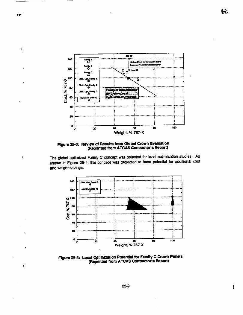
For the purpose of review, F'_ure 25-3 shows the final results from crown globalevaluation studios performed last summer. A detailed description of the ATCAS DBTapproach and crown global evaluation results were documented in a low-numbercontractor's report (currently being published by NASA Langley) and in a paperpresented at the Rrst Advanced Composite Technology Conference. Note the lowercost of one of the Family C designs shown in Figure 25-3 as compared to originalresults. This is due to an improved process plan for long discontinuousfiber/thermoplasticframes obtained from the DuPont Company.
25-7

/
z _ _D
". Jl| '_lo
.-,=. "oi.--l;'.--!--
_ ,
• 1i :
g .E
_1 l!°lii
il",Ji"t|,
I
kw L'_
140
120
xlO0
r:.(Or.,. 8O
_e4.*
_n 60
84O
20
00
" Fm_f II ................ :"............... 0 "'''_ ...................... : ...................... _..........
-I o ............._-.._....;._. ................._.....................i..........
-t _o_.,. ................_ .... -"_---!--'_ ................_.....................* .........
. I_%r.gn_O- • ..... I "L" ::_'*'" 2 : 5": !ll.lt.,r. l , ............. _' ...................... _!......... I
I t_ i 1
-I"-':_"_ .....__"'m _'......................................!.........t
................... :,...................... ;...................... ; ............................................. _ ........
20 40 60 80 100
Weight. % 767-X
Flgure 25-3: Retdew of Results from Global Crown EvtduaUon(Reprinted from ATCAS ConUactoCs Report)
The global optimized Family C concept was selected for local optimizationstudies. AsShown in Figure 25-4, this concept was projected to have potential for additional costand weight savings.
140
120
X 100
r_ 8O
40
2O
h I i i%_C ......... t-.................. ;.......... _-............ -_.........
oo go 40 eo 80 too
Weight. % 767-X
Rgum 25-4: Load Optlmlzrdon PotenUal for Family C Crown Panels(Rqxlmed from ATCAS Contractor'I Report)
25-9 1

,,r
Local optimization progress obtained during the last six months is summarized in Figure25-5. The final crown design is projected to have 18% cost savings and 45% weightsavings, relefive to the aluminum 767-X benchmark. Each of the three tasks supportinglocal optimization were found to have a significant effect on the projected cost andweight of composite crown structures. In addition, design criteda were also found tohave a significanteffect.
Followingglobal evaluation, the tension damage tolerance criteria for failsafe conditionswas modified to account for larger notches and severed frames. It was then determinedthat the original Family C design had a negative margin of safety for fallsafeconsiderations. As shown in Figure 25-5, redesigning the concept (i.e., increasing theskingage) forsufficientdamage tolerance results in both cost and weight Increases.
Process/material relationships need to be understood in order to ensure theperformance, repeatability, and optimization of structures fabrica_ by innovativemethods. In ATCAS, mechanical tests are performed during local optimization togenerate a database for selected materials and processes. This database yields moreaccurate informationon the mechanical behavior of new material forms fabricated by theselected processes. Depending on the results of mechanical tests, designs are modifiedduring local optimization.
As discussed in previous monthly reports, tow-placed laminates were :ound to haveimproved tensile fracture characteristics as related to tape laminates .;ur_sistingof thesame constituents. Figure 25.5 shows that the improved properties of tow-placedlaminates result in significantdecreases in both cost and weighL It was not poss_le todecrease cost and weight by eliminating skin plies in direct proportion to the increasedtension damage tolerance performance of tow-placed laminates, because otherconsiderations (e.g., minimum panel stiffness and stability) became the design driversfor portionsof the crown panel.
A design cost tool (UWCODA) developed at the University of Washington was used tooptimize cost and weight for the Family C crown design. Relationships betweenmanufacturing cost and design parameters (e.g., stringer spacing, material costs,number of skln plies) were developed and input Into UWCODA, together with crownpanel design constraints. Figure 25-5 shows that both cost and weight were reducedsignificantly during UWCODA design optimization. As discussed in previous monthlyreports, stringer spacingwas found to be the dominate cost driver in these trade studies.
The final local optimizationtask invoives fabdca_on trials to further attack cost centersand optimize manufacturing plans. This activity is still in progress for the crown panel(see discussions in Section 4.1,?.). Figure 25-5 shows an estimaled reduced cost foroptimized manufacturing plans on the order of 10%. Cost savings identified to dateincdude(a) reduced number of tools for stinger and frame fabrication,_) lower materialcosts for stringer fabrication (tow instead of tape), (c) increased tow band width fortow-placed skin layup (increased to 6 in. width), and (d) soft toolingconcepts to minimizelabor costs for panel begging. Additional modifications will be made to the crownmanufacturing plans based on the results of fabricationtdals during the summer of 1991.
25-10J

AE:3C
E:3
<
X
(D
_J
O
110
100
9O
8O
OriginalFamilyCGlobalEvaludon
Colt & WldgMEstlmatl
of CriteriaChangesOnDesignCost& WelgM
Rgum 25-5: Summary of Individual Factors AffecUng Local CrownOptimization
4.1.1 Design Concepts
Current Progrelm: The results of the stringer element cost study referred to in MonthlyTechnical Progress Report #24 (Apdl 1991) am presented in F'mgure25-6. As previouslyreported, the result of 1hisstudy indicate that large incmasas in stringer cost relative tothe original cost estimate have liffie or no effect on _e stiffened panel design, withmaximum stringer spacing being the dominant design driver. Costs relating to thenumber of stringers overshadow the costs relating to stringer fabrication and matedalcosts.
Efforts continued toward the completlon of the drawings and purchase orders for thecrown verificationtest program. The current status is shown in Figure 25-7. Effortsduring May focussed on refining the stringer, frame and stringer/frame intersectiondetails for the curved manufacturing demonslxation artlckas(3" x 5' and 7' x 10') as wellas the curved blaxial tension panel (#12). In addition, some progress has been madetoward completion of the purchase order forthe flat stiffenedpanel (#9).
25-11

IF
i 4OO,/,Stdng_FabandMMerill I
2.o 2e0% Slmgw r-tb and Mater/I
19 AS4/3501-6 I_*a,Jc_s -_% Sb',n0err_ _
1.8
•41" ...... li ........................ '1(
1.7 • x xX : x
_" F-hendMamdalCom xx ! . i
• " .iJI. "'11"°" ""1.3>_ "'-'; • • ....
1.2 ": "'"_"
+1.0 :0.9
Awnge Unit Area Weight pb/in2 )
Figure 25-6: Effect of Increasing Stringer Bement Cost on a+ Crown Panel Oeslgn
Diwq_n
I1: 8hloal, AS4,;_44
a: mL,_a.O0..d.gW,_d
B_, A_ OpmWz_
le FIll _ I.tllfllnl¢ ._11, k_4
F_ Ummj UnCmmN,/.UL 2S%Hy_d
It Undelmd
m: RII Unmd_ Slhm¢ Adl¢ AS4
#1¢: FIll Ur_dll SINhnld, 25% Httldd
II1: 8' x I0' Mmn.4El,_g Oorno
#12: C,_n,m:l81_md,AS4,Opm'_md
Ommng _ _ _ Fd_a_,)
• • • • O
• • • • O
• • • • O
• • • • O
O O O O O
• • • • O
• H,m_ _'T C=_,= n_,_ O
• 0 0 0 0
0 _.._,ct c_._ _._._ 0
0 .No(SW_ O .l_W_ • .Co,q_.t
Figure 25-7: Test Panel Drawing, Purchase and FabricationStatus
25-12

Problems ond RecommendaUons: No problems are currentlyforeseen and there areno recommended changes in plans or schedules at thistime.
Near Term Plans: Documentationof the local optimizationstudies will be initiated.
Work will continue on the drawings for the 3' x 5' and 7' x 10' manufacturingdemonstrationsarticles,as well as the blaxial tension panel (#12). Purchase Orders willbe expedited as required to avoid delay in the manufacturingprogress.
4.1.2 Manufacturing Technology
Current Progress: Figure 25-8 shows a curved panel (two "1"frame/two hat stringer)that was fabricated and cured with the new modified soft tooling concept. This 74"radius panel was cured with 150 psi on a steel OML cure tool. The panel shown inFigure 25-8 was the second fabrication bial used to develop an optimaJ soft toolingapproach for the crown manufacturingplans. Additionaltrials are planned using 3' x 5'panels and the final concept wil_be demonstrated with the 7" x 10' crown verificationpanels.
_JLACK AND WH;TE p_G.C:.RAP_
Figure 25-8: Curved Family C Design Concept Fabd_ Using aNew Soft Tooling ConcepL
The modified soft tooikngconcept used to fabricate the panel in Figure 25-8 is shownschematically in F'_ure 25-9 for the current crown design (i.e., J-frames). Figure 25-10shows two types of hat stringer cure tools which were compared in the fabrication trial.
25-13

Thecuretool for the first hat was a silicon mandral. A low coefficient of thermal
e;_pansion (C'I'E) flex rnandral was used as a cure tool for the second hal Bothmandrals were extracted over a tapered skin (0.10" buildup over 3") to evaluate scaJe-upproduction requirements. Soft tooling was fabricated on a fiat panel mockup whichreflected the stringer c_ss sections and panel taper. Stngers were drape-formed ar.edges were trimmed with an u._asonic knife as shown schematically in Figure 25-11.
Figure 25-9: Cross Section of the Soft Tooling Concept
Strinaer Mandrel
Silicone .Low CTE Flex Msndml
Figure 25-10: Stringer Tooling Combinations
Following panel P_dca_on, the sU-aJght(90o) and tapered cut stringer flanges wereinspected and indica_ons show that the soft toolingminimized the resin pooling for boththe 90° and tapered flange edge cuts. Figure 25-12 shows the results of this inspectionschematically. The 90n edge had some edge defects from stringer mislocation and/orstnger edge tmmtng accuracy. Figure 25-12 JllusVatesthat the tapered stringer edgesproved to be more tolerant for Iocationaland trimming inaccuracies,
Umitations of hat stringer mandral extraction and stringer gage thidmess control arecurrently under evaluation. The low CTE flex mandrels were found to extract easier thanthe silicon mandral. The typical skin thinning which has been observed between thewebs of hat stringers in past fabrication tals occured in the current study with both thesilicon and low CTE flex mandrals. The low CTE flex mandraJyielded a more con._stenthat cross sec_onal shape than the silicon mandraL Morn measurements along thelength of the stinger will be taken after nondasUuctlveinspectionis completed.
25-14

[
Drape Form Charge Cured Hat
Flgure 25-11: Tdm of Drape Formed Strlngem
An P,nalysis will be conduced to determine costs of the low CTE flex_le mandrai. Oneadded cost to the low CTE mandral Is that of an added radius noodle.
cut
Fiber Wdnkles(Ove, r cut) _"="=_ Resin Pool
fSkln Thlnnlng
ZammCG._
I
SldnThinning
Figure 25-12: Schematic of Stringer Details Resulting from SoftTooling Fabrication Tdal
25-15!

The winding tool for the 3' x 5' and 7"x 10' demonstration panels is stillunder fabricationand will be completed and shipped to Hercules in the middle of June. Fabrication of theoutside mold line (OML) cure tool has had schedule delays and will be finished at theend of July. Cure mandrals and soft tooling material are on order for the 3' x 5' panels.A mock-up to build the 3' x 5' softtooling is being designed to handle both the 3' x 5' and7' x 10' demonstration panels. The panel mock-up will be made of a fiat graphite/epoxyplate with metal stringers and graphite/epoxy frames. Fabrication of the 3' x 5' skins willbegin oy the end of July.
Work began on the fabdcation of the crown verification test hardware. The first two fiatpanels for unstiffened uniaxial (small coupons) and blaxial tension testswere tow-placedat Hercules, Inc. The first panel (#1) was scrapped due to an improper cure cyclecaused by a thermocoupte failure. This panel will be remade. The second panel (#2)was subsequently cured successfully.
Problems and Recommendation=: Fabdcation of the crown manufacturing and testyerifica_on panels at Hercules, Inc. is significantlybehind schedule. Delays are due tobo,'h limited machine availability and the amount of procurement paperwork flow. A newfabrication schedule will be developed during June to understand the influence of thesedelays.
Near Term Plane: The intricatebond panel produced in a soft toolingtrial (Figure 25-8)will be ultrasonically inspected and waJpage tests will be conducted. After inspection,the panel will be sectioned and measured to evaluate the panel dimensional accuracy.Planning will continue for additional, larger, soft tooling trials. All soft tooling andaesemb_y designs for the 3' x 5' and 7"x 10' panels will be finished and tool fabricationwill begin.
Dudng June, fabrication of the crown vedficalJon tests will continue. The remainingpanels to support small coupon and biaxial tension fracture testing will be tow-placedand cured.
4.1.3 Supporting Technology
Current Progreu: A meeting was held between Boeing personnel and Dr. Chang fromStanford Universityto discuss the progressive damage modeling beingdeveloped there.After reviewing the progress, it was determined that a plate implementation of the modelwould not be possible by the contTact-enddate (September 1991), limiting applicationsto the current plane-streas implementation. Methods to avoid numedcaJ instability forlarge damage zones have been implemented. During the remainder of the conVact, thefollowing activitieswill be completed.
, AnaJ_cal studies to investigate the ability of transverse ply strength,fiber/matrix shear strength, and fiber strength differences to account forexpedmentaJly-observed improvements in tension fracture performance oftow-placed laminates when compared to tape laminates
25-16
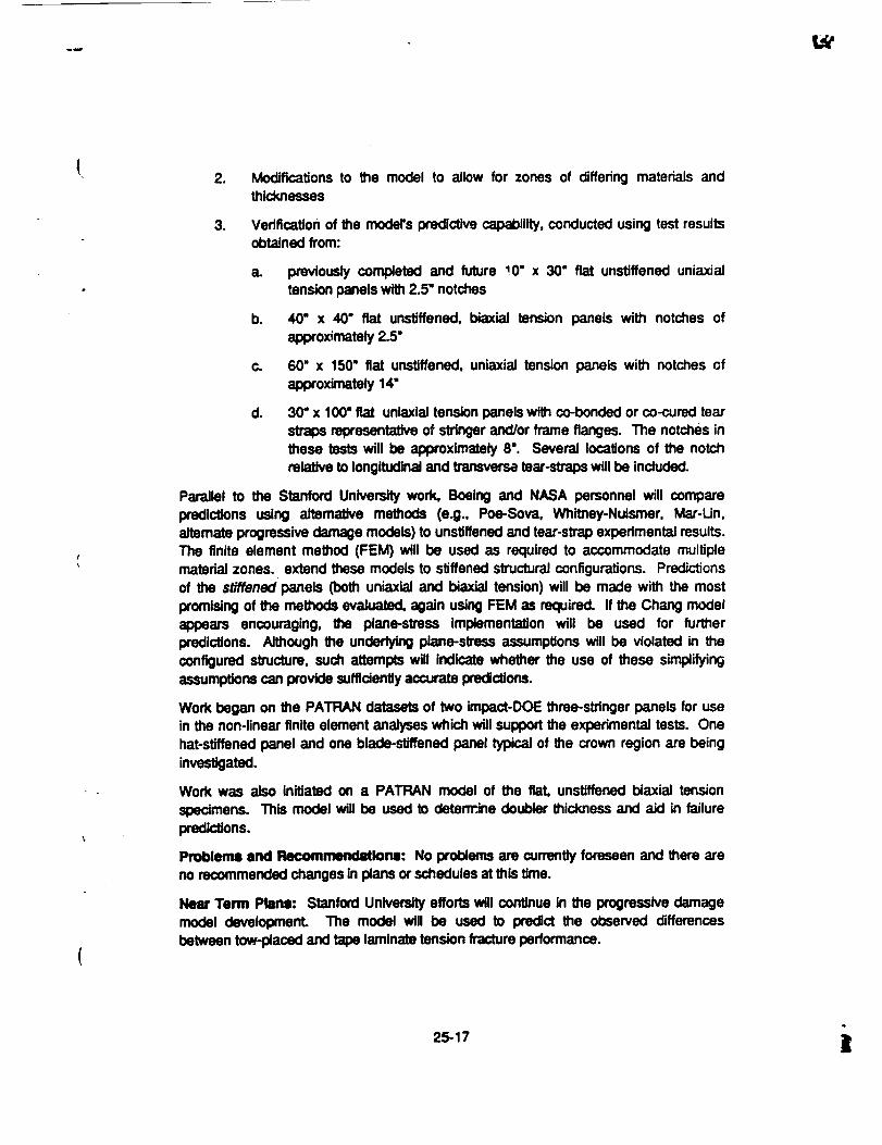
2. Modifications to the model to allow for zones of differing materials andthicknesses
3. Verification of the model's predictive capability, conducted using test resultsobtained from:
a. previously completed and future !0" x 30" fiat unstiffened uniaxiaJtensionpanels with2.5" notches
b. 40" x 40" fiat unstJffened, biaxiai tension panels with notches ofapproximately2.5"
c. 60" x 150" fiat unstlffened, uniaxial tension panels with notches ofapproximately 14"
d. 30" x 100" fat unlaxial tension panels with co-bonded or co-cured tearstraps representative of stringer and/or frame flanges. The notches inthese tests will be approximately 8". Several locations of the notchrelative to IongitudinaJand transverse tear-strops will be included.
Parallel to the Stanford University work, Boeing and NASA personnel will comparepredictions using alternative methods (e.g., Poe-Sova, Whitney-Nuismer, Mar-Un,alternate progressive damage models) to unstiffenedand tear-strap experimental results.The fnite element method (FEM) will be used as required to accommodate multiplematedaJ zones, extend these models to stiffened slnJcturalconfigurations. Predictionsof the stiffened panels Coothuniaxlai and biaxiai tension) will be made with the most
promisingof the methods evaluated, again using FEM as required. If the Chang modelappears encouraging, the plane-stress implementation will be used for furtherpredictions. Although the underlying plane-stress assumptions will be violated in theconfigured structure, such attempts will indicate whether the use of these simplifyingassumptionscan provide suffidantly accurate pmdi_ons.
Work began on the PATRAN datasets of two impact-DOE three-stringer panels for usein the non-linear finite element analyses which will support the experimental tests. Onehat-stiffened panel and one blade-stiffened panel typical of the crown region are beinginvestigated.
Work was also initiated on a PATRAN model of the flaL unstiffened biaxial tension
specimens. This model will be used to determ.ine doubler thickness and aid in failurepredictions.
Problems and Recommendations: No problems are currently foreseen and there areno recommended changes in plans or schedulesat this time.
Near Term Plane: Stanford University efforts will continue in the progressive damagemodel development. The model will be used to predict the observed differencesbetween tow-placed and tape laminate tension fracture performance.
25-17 ]_

Workwillcontinueonthefiniteelementmodelingeffortin supportof plannedfiatthree-stringerpanelbucklingtests(Section4.1.4).
WorkwillaLsocontinue on the modeling of the fiat, unstJffenedbiax_ tension panels.Doubler requirementswill be defined duringJune.
4.1.4 Mechanical Tests
Current Progress: Work conUnued on the interpretation of tension-fracture couponresults. Due to manpower restrictions, efforts to finish reducing the intraply hybriddesign-of-expedments(DOE) results have been delayed.
Plans are under development to refocus the Universityof Utah (Bascom) subcontract toaddress the failure mechanism differences between tape and tow-placed laminates. Thedetailed plans will be reported in future reports. As an initial step, some tensile fracturecoupons of 50% AS4150"/0 S2-Glass hybrid material will be tested to identify the failuremechanisms. These specimens (3.5 ° wide with 7/8" notches) have been received byUniversityof Utah,
The final report on the tension fracture behavior of IM7/977-2 has been received fromSan Jose State University and is being reviewed. Salient results will be presented infuture monthlyreports.
Development of the plans for crown verification tests continued. The cooperative effortwith the Mechanics of MateriaLs Branch (C. C. Poe) at NASA-I..,_Iey to test andevaluate the results from fiat unstiffened biaxial tension panels appears on back.Checkout of the test fixture at Langley is nearly complete, with results indicating goodgrip alignment. Coordinationwith the Non-destructiveMeasurement Science Branch (J.Heyman) is continuing to use the laser speckle pmfilometer to obtain full-field in-planedisplacement fields.
Testing of rite fiat unstlffened unlaxlal and blaxlal tension panels was originallyscheduled for June and July. However, a_ mentioned in Scion 4.1.2, fabrica_on isbehind schedule. A new test schedule will be developed in June.
Planning for the compression testing of the fiat throe-stringer DOE panels is continuing.After furl_er prediction of the expected failure modes using approximate solutiontechniques, tt was decided to test only the panels with a skin thickness of 0.089".Detailed predictions indicated that the column instability of the thicker panels occursshortlyalter skin budding, a failure mode not representative of ATCAS fuselage designs(i.e., eit_r for_rard-cmwnor aft-keel). The data obtained from such tests would not beapplicable to crown panel verification. Therefore, one hat-stiffened and one blade-stiffened panel will be tested in compression. Cost estimates for panel preparation andtesting are pending.
Work on the planning of curw.,d, three-s_inger panel compression post-budding testshas been initiated. These panels are to be _ed as manufacturing demonstrationsand will reflect the crown panel design geometry.
25-18

Initialworkona cripplingtestprogramto validatethecrownpaneldesigndetailswasinitiated. Backgroundinformationon cripplingtestswasgatheredand evaluated.Concern for the crippling response of configured stiffeners and the effect of the testelement length on the cripplingdata was emphasized. Currently, a test matrix is beingformulated to address hat and blade stiffener geometries, both of which are being used
in the crown panel design studies. Also, the effects ot test element length for larger L'/pvalues, the effect of stringerdamage, and the effect of a high temperature environmenton the IocaJbucklingand cripplingfailure are being considered. Test elements are beingobtained using the impact-DOE panels and the manufacturing demonstrationpanels.
Problems and Recommendations: No problems are currently foreseen and there areno recommended changes in plans or schedules at this time.
Near Term Plans: Work on the intraply hybrid DOE will continue as manpower andschedule allow.
Tests of the center notch hybrid coupons at the University of Utah should be starting inthe next two weeks.
Review and interpretationof the test report on the notch size/shape testing at San JoseState Universitywill continue.
A schedule for all the verification testing will be developed duri.'xj June. Efforts willcontinue towards planningfor these tests.
The preparation of the fiat three-stTinger panels for testing will be initiatedduring the nextreporting period. Work will also continue on the curved three-stringer panel test plansand the cripplingtest matrixand test plans.
4.2 Keel Panels
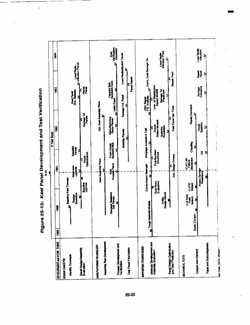
The schedule for activities associated with keel panels is shown in F'_ure 25-13. Work
which was reported as behind schedule last month (i.e., baseline concept design layoutsand impact damage resistance tests) was completed during May. Design drawings andmanufacturing plans for alternate concepts remain behind schedule.
4.2.1 Deslgn Concepts
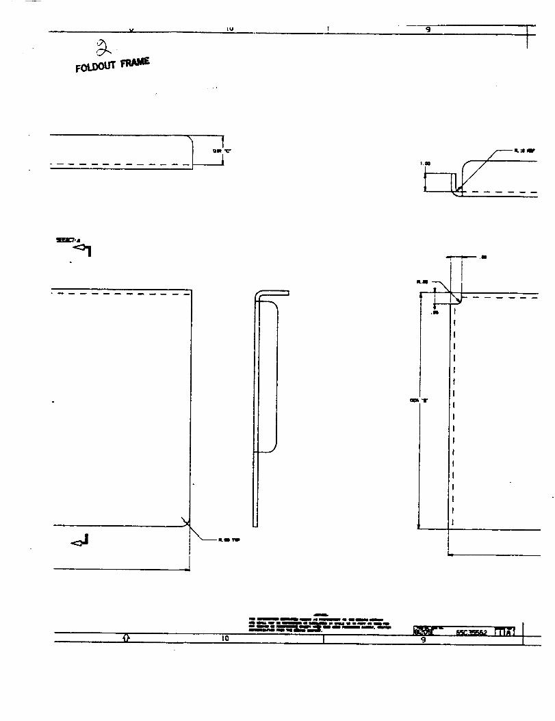
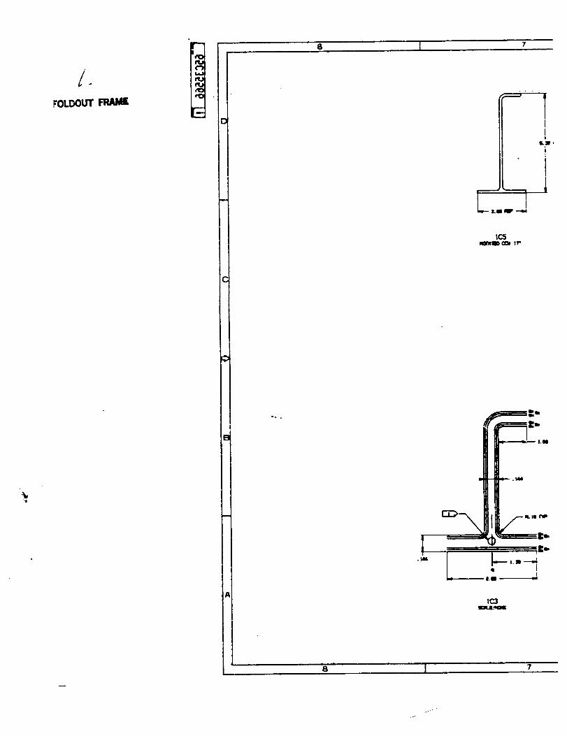
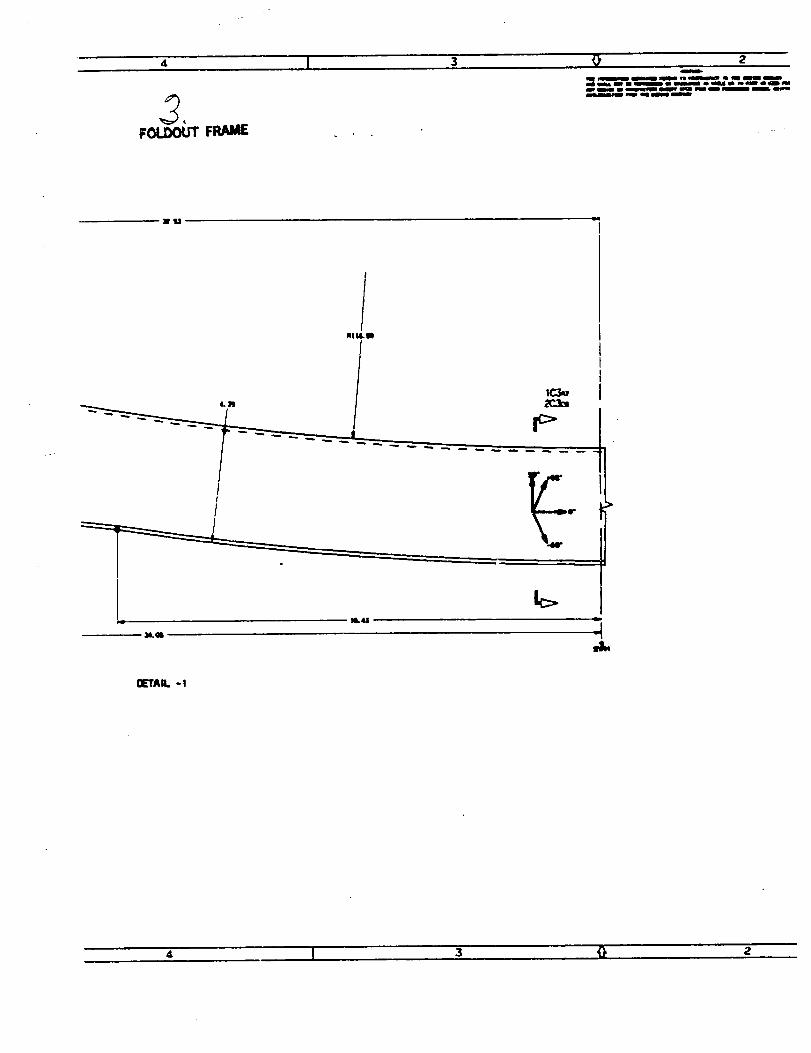
Current Progress: Work continued on the keel panel designs. The design status isshown in Figure 2.5-14, and the concept variables am contained in l_ure 25-15. Theintercostal drawing for both Design DI and D2 is contained in Appendix B. The DesignDI cargo floorframe drawing is shown in Appendix G. The drawings of the frame det_Isand cargo floordetails am contained inAppendices D and E, respectively. The sizing ofthe CI design is complete for the skin, stringer and discrete keel chords and thedrawings are being prepared. The drawing for the cargo floor details for this design iscontained in Appenc_xF. The sizing of the Design C2 skin, stringer, and smeared keel
is still being developed.
25-19 _',
C
I] c_||
G t _ sa,._,- fl'_ ---
,T ! ! ,
I,_11 1.,-,
J i "
! I|c :
• Ii
2 gt__II'_,IP
c
! '!
io'J!,

om_ _ Eswmm=
Fw,ay C O_C_ mevee_0_ Q 0 0cemo noo, k*m 4) • @
0 0 0
• 0 0
O_Cm mev_ @ 0 0C_pFk:, _ 0 0 0
0 0 0
mmamm. 0 0 0
am= • • •F_may o ou0. O_A Cemo noo, eNm • • @
mmmo. • • •
8Mns • • •o_om caqpR=r _ • • @
mmmmmm • @ @
oee_ Oe sir • • @CaqoRw emm • • •
• 0 0
Figure 25-14: 51atus of Keel Design Work
I_1, IIAMCmomo
/
"_" "f Ir_ -- -- "I"
l m
*_p -/.
mlome, ae4_l_O_
Figure 25-15: Keel Oesign Concept Varlable_
Work on keel panel cost estimatingcontinued. To date, reoJrdngand nonrecurringlaborestimates have been obtained for the skin, cargo floor frame, cargo floor beam,intero0stal, and keel frame of design concept DI. Estimates for D1 installation andmatedal costs are in work. Recurring and nonrecurringlabor estimates have also beencoml:detedfor the D2 skin, cargo floor beam, and keel frame. Keel cost results will besummarized in future mor_ly reports, followingreview by the ATCAS DBT.
25-21

ProblemsandRecommendations:Noproblemsarecurrentlyforeseenandtherearenorecommendedchangesinplans or schedules at thistime.
Near Term Plans: Work wig continue on the C1 and C2 skin, stringer and keel chorddesigns and the sizing of the mmaJningdetails will begin. All coml0onentsof the costestimate for Designs D1A and D1B will be completed.
4.2.2 Manufacturing Technology
Cun'ent Progress: The installation plan has been completed for the sandwich keelDesigns D1A and D1B. Appendix G contains a pictorialsequence of the assembly to aidin visualization. The cured keel panel conr_uration is shown in F'¢jure SK-1 in thatappendix. The panel will be made using an inner moldline (IML) tool. The decision touse an IML fooling concept was largely driven by the thickness tolerance build-uppossible in a 1.3" thick prepmg laminate (Figure SK-2). The re_onak_ is to push thevariations outside the airplane thereby eliminatingtheir effect on the inside chord details.
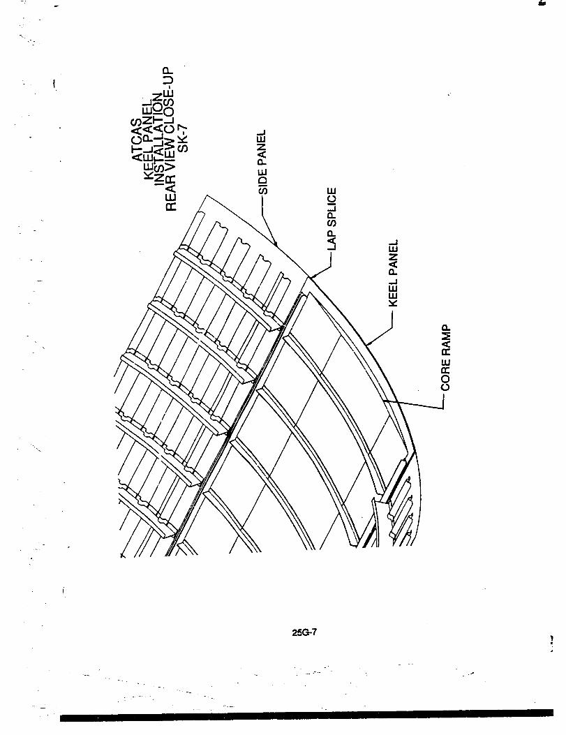
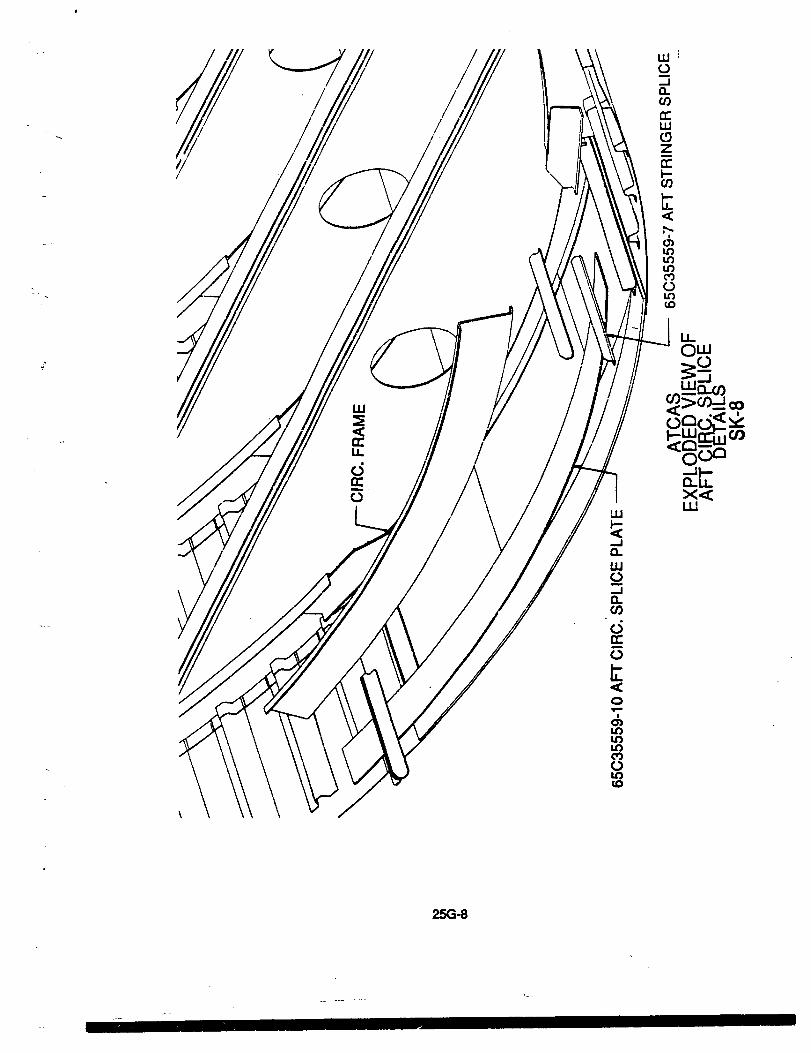
The side panels are located and lapped under the keel panel and the longitudinalbladestringer positioned (Figures SK-3 through SK-5). Two tandem robots perform the panelfastening, with one ddmng, countersinking and inserting the bolt and _ other instaJlingthe lockbolt collar and tensioning the bolt. The same tandem robots used on thelongitudinal lap splice will be used for the aft Section 46 splice (F'_jums SK-6 throughSK-10).
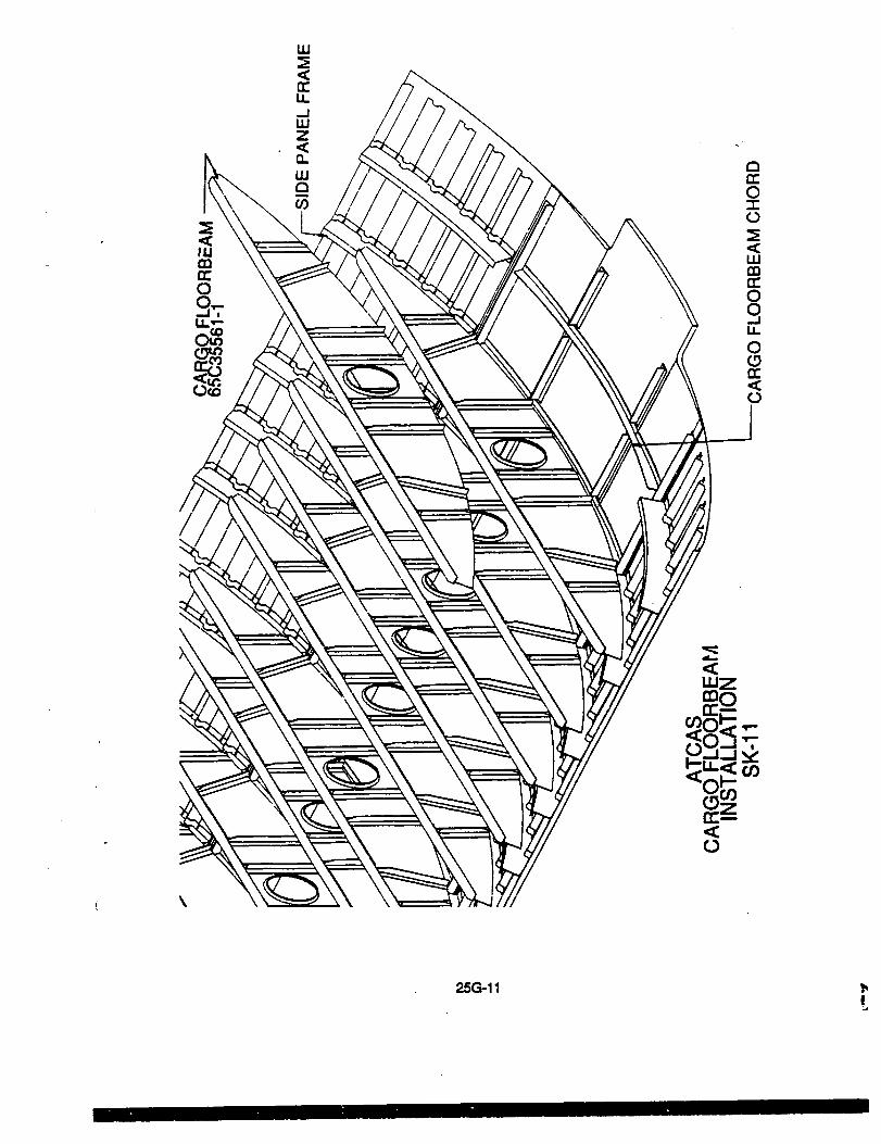
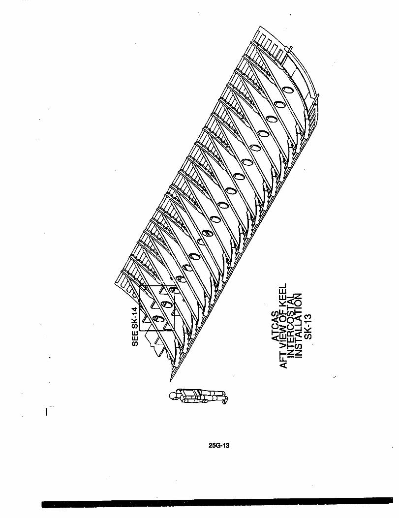
The full depth cargo flood)earnsare mechanically attached to the co-bonded chords onkeel panel and side panel frames (Figure SK-11). The keel intercostals are then
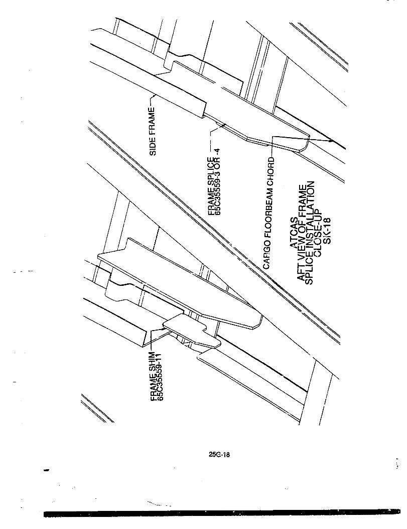
mechanically attached to the co-bonded intercostal chordsand one full-depthfloorbeamstiffener (Figuras SK-12 to SK-14). The details at the frame splice am then mechanicallyatta_ed (Figures SK-15 to SK-18).
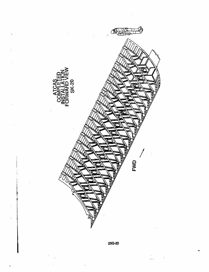
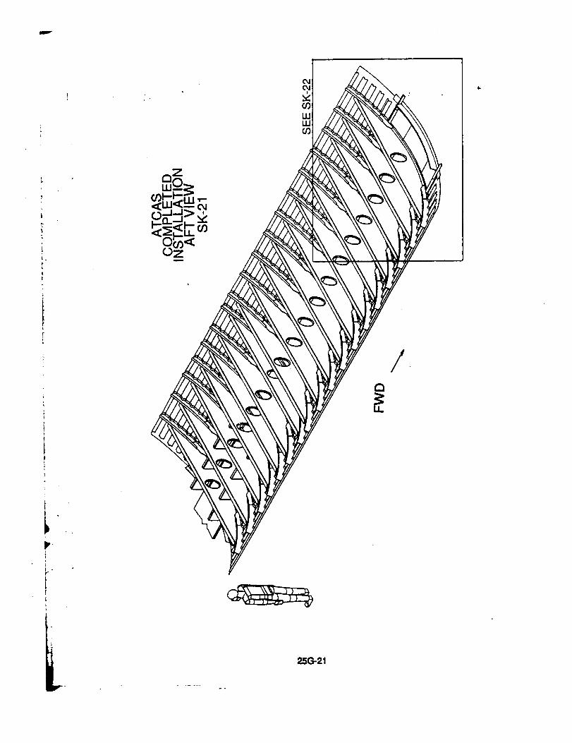
The forwaJ¢lsplice is accomplished through the use of two titanium _ plates (F'_jureSK-19). The final configuration of sandwich keel Designs D1A and D1B is shown inF'¢juresSK-20 to SK-22.
The subcontract with Sundstrand to develop ins_u forming foams has been in Place 4months. Several restdctiue clauses were identified in the Hercules neat resin "Non-
Analysis" agreement. These clauses have been modified to Boein_s satisfaction andthe agreement finalized. One gallon of neet resin will be shipped to SundsVand thesecond week of June.
Su_ has identified several a_srnative resins for use in ins_u foaming. Theseresins include a low viscosity epoxy and powder cyanate ester. Low viscosity resinsmay ease mixing of ingredients,while the powder resins are similar to the thermoplasticmatedal form used in tileir currantprocess.
Boeing is initiating a second subconUactwith Sundstrand to study the manufacturabilityof keel gage sandwich structure. This studywill consistof sandwich manufacturingtdp_including thicker facesheets, different thickness cores and sandwich with thidme,3.s-
25-22

taperedfacesheets.Apreliminarystatementofworkhasbeendraftedandwillbefurtherrefinedfollowingconsulta_nwith Sundstrand.
The studyon the use of TTU for inspectingfoam sandwichstructurecontinued. A reviewwas made of further effortsneeded to complete the study, and a plan set up. No furtheranalysis of the previous data set will be made. Instead, measurements will be taken onfoam blocks to characterize properties of the Rohacell foam. The blocks have been cut
in steps to allow propagation to be analyzed as a function of distance. Propagationspeed and attenuation _ be characterized as functions of frequency. This will allow thelimits of TTU scanning to be defined, and proceduresfor scanning foam sandwiches tobe set up in terms of frequency, sampling rate, and sample duration. Scans of panelswith implanted defects will also be made and analyzed. Documentationof the study hasbegun.
Problems and Recommendations: No problems are currently foreseen and there areno recommended changes in plans or schedulesat this time.
Near Term Plans: Work will continue in developing manufacturingplans for keel panelelements and Installation. Most of the remaining work is with Family C concepts.
Boeing will confe,"with NASA resin experts and Sundstrand to determine the suitabilityofthe Hercules and other altemative resi,s. Compatibilitywith the face.sheets must beconsideredfor any resin selected.
Boeing representatives w_l meet with SundsVand to review and better define a second
subcontract to investigate the manufacturabilityof keel type stricture. A design buikJte_n inducing both Boeing and Sundstmnd structures, materials, and manufacturingpersonnel will be formed to consider issues assodatsd with the core material choice.
In the study to inspect foams, TI'U measurements will be conducted on the _teppedfoam blocks and the defect panel, and the results will be analyzed for a propagationmodel. Test procedures will be developed for scanning foam panels. Effortswill alsocontinue towards completion of the documentalJon.
4.2.3 Supporting Technology
Current Progress: A number of design drivershave been identified for the keel panels.The _ load case is a 2.5g symmetric maneuver which causes body bending andputs the keel in compression. This compmeslon load is introduced into the forward endof the keel as a conce_ force, as the loads am forced around the large cutouts forthe wing center secUon and wheel well. Typical aluminum designs carry theseconcentrated loads through two massive keel hearns which am mechanically attached tothe stiffened keel skin. The high Sl_Ce loads am tempered somewhat in Designs D1, D2and C2 by panellzing the loads into a thick laminate that replaces the mla_vely thin skinand large keel beams of the aluminum concept. The concenVated load is Vansferredrapidly from the keel beams (discrete or panelized) into the stiffened skin and thens_,eared out into the rest of the panel. The resulting compmss4onand shear load
25-23

,/jr!
contourswere shown in Figures 22-12 and 22-13 of Monthly Technical Progress Report#22 (February 1991). The figures _ show the jump in loads in the area near the sidepanel cargo door opening.
Figure 25-16 is a schematic showing where specificdesign issues tend to be cr_.'caJinthe keel panel. The topdrawing shows the skin of a Family C (i.e., skin/stringer)conceptwith discrete aluminum keel chords. The figure shows the important areas of loadredistribcClon:the keel beam to skin joint, and the areas of high shear adjacent to thekeel beam. Most of the skin is dominated by panel compression issues and minimumstiffness requirements. Minimum skin buckling tends to be critical in the areas ofincreased loads near the cargo door opening. The longitudinaland aft circumferentialsplice joints sometimes control the minimum skin thicknesses, Attaching discretealuminum keel chords to a Gr/Ep skin presents the additional problems of thermalmismatch, which can add to the skin loads, and galvanic corrosion, which may require afiberglasspad between keel beam and skin.
The bottom drawing of F'_ure 25-16 shows the critical design issues for a Family D(sarm'w_) skin. Note that minimum stiffness requirements are ger,Pr_;!_!not critical inthe sandwich structure which is more efficient in shear than the skin/slringers. In thearea where the solid wedge transitions to core, the resulting shifts in the neutral axiscause significantkick loads. Other design issues are similar to those mentioned for the'C' skin.
"C'SKIN
s=_r,_sm==
" ................ ' i .iF1"ctRcl.sa-
: i- i
"O'SKIN
Rgure 25-16: Critical Keel Panel Deldgn Issues
25-24
lrlm
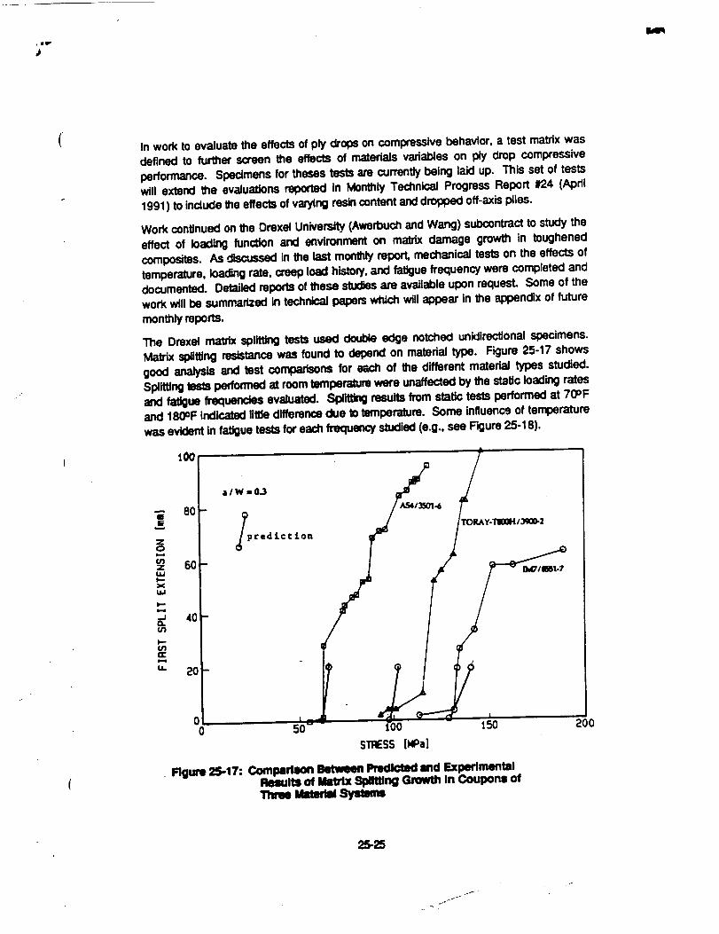
In work to evaluate the effects of ply drops on compressive behavior, a test matrix was
defined to furlfler screen the effects of rnatedals variables on ply drop compressive
performance. Specimens for theses tests are currently being laid up. This set of tests
will extend the evaJuations reported in Monthly Technical Progress Report #24 (Apdl
1991) to incJucle the effects of vatyfng res/n content and d_ off-axis piles.
Work continued on the Drexel University. (Awe_ouch and Wang) subcontract to study the
effect of loading function and environment on mabCx damage grow_ in toughened
comlx_tes. As discussed in the last monthly report, mechanical tests on the effects of
temperature, loading rate, creep load history, and fatigue frequency were completed and
documented. Detailed reports of these stud.s are available upon requesL Some of the
work will be summarized in technical papem which will appear in the appendix of future
monthly reports.
The Drexel maffix spiitting tests used double edge notched unidirectional specimens.
MaVix splitting resistance was found to depend on matedal type. Figure 25-17 shows
good analysis and test comparisons for e;;ch of the different matedaJ types studied,Splittingtests performed at room temperature were unaffected by the static loading ratesand fa_ue frequendes evaluated. SplittJn0 results from static tests performed at 70°Fand 180OFIndicated little differenceclue to temperature. Some influence of temperaturewas evident in fatigue tests for each frequencystudied (e.g., see Figure 25-18).
e
zoi-i
ulz
idJ
XMJ
tL
6O
40
20
00 50 150
STRESS[ROa]
• Figure 2$-17: Comllalllon Betvmen Predicted lind ExperimentalRUuItll of _ SpJllJng Growth In Coupons ofThme Um_ Syleem
25-25
j-

150
i
_1
)-i.J
a. 5o(n
.J
I=ZI
0
0 5000 10000 15000 20000 25000
CYCLES
150
i
.J
u) 50
me
0
0 5000 10000 15000 20000 25000
CYCLES
Rgm 25-18: Effect of TmnlXnlum on Fstlgue Growth of MatrixSpilffing: at 1 Hz (above); at 0.1 Hz (below).
Drexel tests for maldx splittingand mode I interlaminar crack growth (double cantileverbeam. DCB, specimens) have indicated some influence of creep load history. AJItestsperformed to date have been done in a room temperature environment. Creep loadsheJd for up to 50 hours on DEN specimens have resulted in some matrix splirdng,followed by a delay in additional growthuntilhigher loads. Creep loads held for up to 50hourson DCB specimens have resulted in no visual crackgrowth, followed by a delay inadditionalgrowth untilhigher loads. In each case, the change in behavior is on the orderof 10=/o,which is dose to the expected matrix stress relaxation for room temperaturecreep tests. Future lasts will accelerate the effect of time with the help of elevatedtemperature creep. Creep load histories are crucial to the framelskJn bond whichsustains pressureloads duringflight.
Problems and Flecommendatlons: No prot_ems am currently foreseen and there areno recommended changes in plans or schedules at this time.
Near Term Plans: Additionaldesign drivers may be identifladas the Family C designscontinueto be developed.
Fabrication of the ply-drop specimens will continue, in order to support the test matrixoutlinedabove.
A limitedeffort will continue to evaluate the effect of creep loadinghistoryon interlaminarcrack grow_ in toughened compositesat Drexel University(Awerbuch and Wang). Thiswill aid in ltm development of test and analysis methods for new work at Drexelsupportingan evaluation of the frame/skin adhesive joint (see Section 4.4.2, SupportingTechnologiesfor Frames and AttachmentDetaJis).
- T
4.2.4 Mechanlcal Tests
Cummt Progress: Impact damage resistance DOE impacting is complete. All panelshave had ultrasonicinspectionsperformed to map out the extent of all impact damagestates on each panld. Detailed time-of-f,ght pulse-echo inspections of individualdamage sites have begun.
The _ffened panel warpage studycontinuedwith the delivery of an approximately 2" by2' manufactudngdemonstration panel to the test lab. This panel incorporates a curvedskin, two s/tffeners,and _o frame elements, tt will be measured for waq_age using theshadow Moire technique.
Research studies on sandwich core materials continued _. The University of Iowa
(Lakes). A significantamount of work was documented in a Masters thesis for larstenLynn Elms (Copies available upon request). In addition, work with metallic m-entrantfoams used as model materials to evaluate the effects of a negative Potsson's ratio onmechanicalperformance wM summarized in a technical paper. This paper is inciuded inAppencgxH foe NASA's review. Please submitany recommendedchanges for this paperto _ authors at Universityof Iowaw_in _le next month.

r ix
Problems and Recommendations: No problems are currently foreseen ancl there areno recommended changes in plans or schedules at this time.
Near Term Plans: Data from detailed Ume-of-fllght puise-echo inspections wil! beinterrogated using 3-dimensional imagery to better conceptualize the stnJcturalsignificance of the interconnecting delamlnations and ¢anaverse cracks. Fiber failurestudies will begin with the identification of candidate impact sites for dep_,.
The results of the current sandwich impact damage study will analyzed, taking intoconsideration the design-of-experiments test matrix. The condusions and observationsfrom this work will be used to scope further structural sandwich studies. The results ofthe current study will guide future coupon and sVucturaltest development. This work willconsider and may be coupled with the research effortbeing pedormed at Sundstrar_.
Warpage measurements for a curved, stiffened panel with frame elements will becollected and correlated with the various manufacturing details of the panel. The finiteelement models of the warpage panels will continue to be refined, including one whichincorporates the attached frames.
Testing to examine the effect of several impact damage repair concepts are beingconsidered. These tests would examine the effect of low cost, simple repairs onsublaminate stability.
Work will continue with damage resistant core materials at the University of Iowa(Lakes). A second subcontract will be issued to analyze and test foam materialsfabricated by the Sundstrand subcontract.
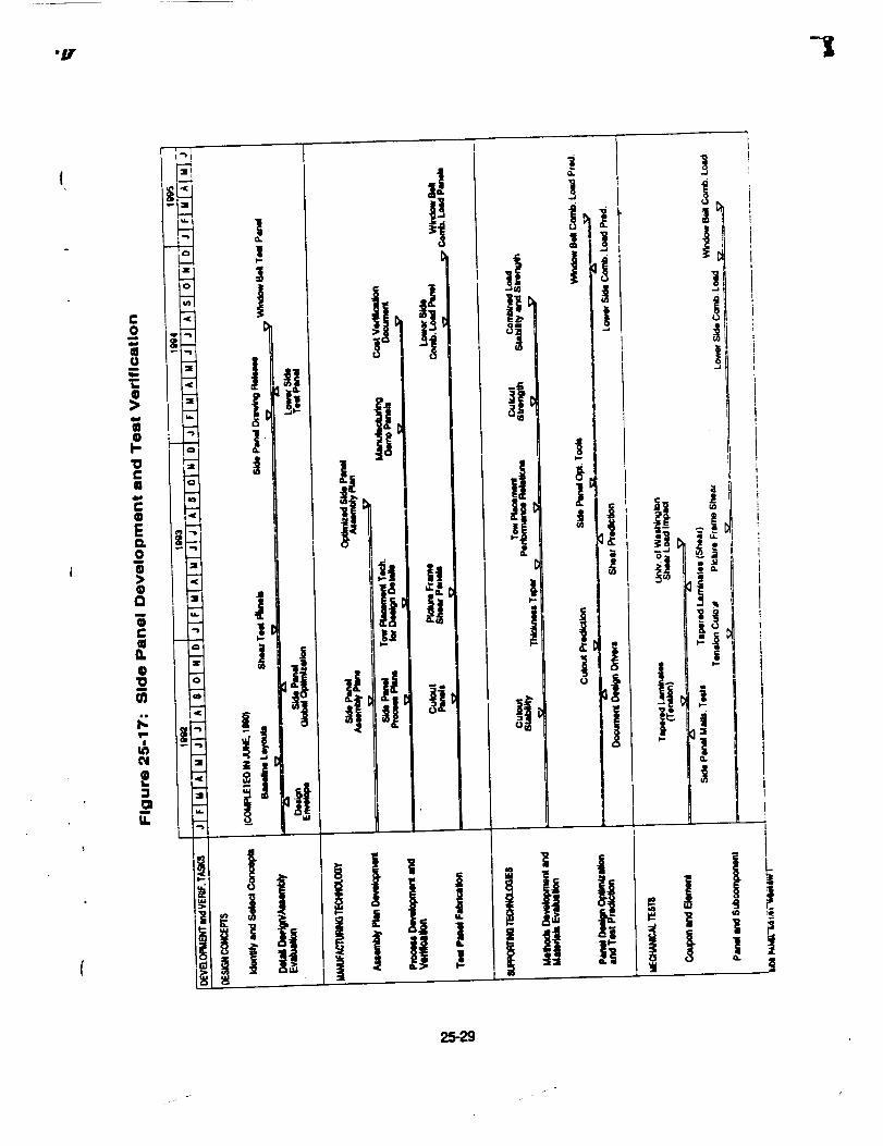
4.3 Side Panels
The schedule for activities associated with window belt panels is shown in Fagure25-17.Work in this area is scheduled to re-start in the fall of 1991.
4.4 Frames and Attachment Details
The schedule for activities associated with ,Yames and attachment details is shown in
Figure 25-18. Work with the initial braided composite test matrix remains behindschedule. Fabrk:ationtasks for this effort have been completed. Tests have slatted atthe Mechanics of Materials Branch, NASA Langley.
4.4.1 Mlmufactud_T_h_logy
Current Progress: Work by Boeing He,copters (BH) continued on the coordination ofmanufacturing/tsst plans for braided materials selected for crown frame aPl_ations.Fabrication of bralded/RTM panels to yield spe_ens for material characterization wascompleted at Fiber Innovations.
25-28
/
•y -I
I! ti
f
it
JJ
/. i

Er-o
=<
C(I
@EL
U.
1"I
m¢_
i
Q.
!1
!1]
25.3O

The RTM tool for 3' frames was finished and shipped to Fiber Innovations. This toolingis currently being tested for vacuum integrity and proper sealing. The design of the 8'RTM tool is still under review. A contact for the 8' tool was released and final drawingrevisionswill be based on the results of 3' frames that will be buiRin June.
The results of thermoplastic rivet lap-shear tests were sufficiently encouraging thatCherry were asked to demonstxate rivet instaJlalJonsat the NASA ATCAS Phase AReview held at Boeing on May 15-16. Cherry developed prototype portable rivetingequipment which was demonstrated to an ATCAS team member dunng April. Thisequipment was used to successfullyinstall rivets in CFRP plates at the review. The nextstep in the development of these rivets is the inclusionof representatNe circumferentialframe web splice specimens in the BH splice test program.
Another potential application for thermoplastic rivets is considered to be the attachmentof glass fiber reinforced plastic (GFRP) plates as repair patches for damaged carbonfiber reinforced plastic (CFRP) laminates in tension dominated structure. The GFRP "material has very good tensile strength properties and the lower modulus for a patchmateriaJwould pull less load into the repaired area. Past mechanically attached repairsof CFRP stTuctureshave _lized metal plates which have the effect of increasing thestructuralstiffness locallyand, thereby Increasing the load at the repair. This can lead todurabilityproblems and failures in the mechanical attachment.
Problems and Recommendations: No problems are currently foreseen and there areno recommended changes inplans or ._chedulesat this time.
Near Term Plane: All bra/ded/RTM panels will be de;ivered fo NASA Langtey forspecimen preparation. Eight 3' frames will be braided and resin transfer mo_ed. Twoframes will have variations of noodle types and cap preforms which will be used forframe/skin bond tests.
Future work utilizingthermoplasticrivets will be coordinated with mechanically fastenedjoint tests. The use of thermoplastic rive_sin crown and keel panel repair concepts _11also be considered.
4.4.2 Supporting Technology
Current Progress: All tabdcation taskswere completed for the initialbraided compositetest matrix comparing two processes: (1) formation by sub_c_r_ gral_ fiber prefom_sto a RTM process, and (2) consolidation of a commingled thermoplastic/graphite fiberpreform. Specimens were shipped to NASA Langley for test preparation.
Work continued in planning Drexel University (Awerbuch and Wang) tests to evaluatethe skin/frame adhesive bend. Basic characterization tests will include delaminalJon
crack growih with mode I (DCB) and II (ENF) specimens. In addition, skin/frame bondelement tests will be performed using specimens cut from crown manufacturingdemonstration panels. A preliminary configurationfor the skin/Irame bond test is shownschematically in F'_um 25-19. The initial set of tests _nll smesn different design and
25-31

manufacturingvariablesfor the skin/frame bor_l detail (e.g., v_.rtationsin the "noodle"insert used to filla gap at the web/flange intersection).
3In.
12 in.
Figure 25-19: Preliminary SIdNFrame Bond Test Element Geometry
Problems and P,ecommendatlons: No probternsare currently foreseen and there areno recommended changes in plans or schedules at thistime.
Near Term Plans: In the University of Washington (Sefeds) subcontract, work willcontinue on the viscoelas_c characterization of 350°F cudng film adhesives. Resultsgiving the shift factors for creep, stress relaxalion and DMA measurements on theNarmco 1515-3 adhesive are scheduled to be completed in time for the next monthlyreport.
Specimens will be fabricatedfor initial Drexel tests to screen skin/frame bond design andmanutactudng variab/es. These tests will also enable Drexel to evaluate the testelement geometry and material fa/lure mechanisms. Test specimens will also befabricated for mode I and II de!arninationcrack growthof the skin/fr-',=meadhesive bond.
4.4.3 Mechanical Tests
Currlmt Progress: Specimens were delivered to NASA Langley to start braidedcomposite testing. Two sets of specimens will be tested: (a) crown materialcttara_dzation (see Sec_on 4.4.1) and (b) initial brawled composite test matrix (seeSect_ 4.42.). Since more braided panels were fabricated for crown material
25-32
i
1
.J

characterization than originaJly planned, some additJonaJ tests will 1_ performed. Theseinclude:
- tension after impact
- transverse tension
- specimen width effect
- impact damage characterization
- additionat fatigue (R = 10, -1 ).
Development of a bored joint test plan required for the assembly of large, stiff cobonded
structures continued at BH. Preliminary tes_. specimen confk:jurations have been
developed to s/mulate the circumferential splice, longitudinal splice, and frame inner
chord splice. The specimens have been configured to examine the joint component
laminates under pure bearing, pure bypass, and interning bearing and bypass loads. A
preliminary test plan was presented at the NASA review in Sear'de on May 15 and 16,1991.
Problems and Recommendations: No problems are currently foreseen and there are
no recommended changes in plans or schedules at this time.
Near Term Plans: Braided composite testing will start at NASA Langley, with a large
portion of the tests scheduled to be completed during June, 1991.
Evaluation of methods for possible simplification of the circumfere,'*_al joint will continue..
Configurations for biaxial testing of specimens simulating the lot. 'Jdinal splice will be
evaluated. Availability of crown panel and braided frame material for test specimens wi_]
also be assessed.
4.5 Full Barrel Studies
The schedule for activities associated with the full barrel section is shown in Figure 25.
20. The only ongoing a_vity is consideration of the total barrel assembly issues as they
relate to the design concept development.
4.6 Design Cost Model
The Phase A schedule for activities associated with the design cost model is shown in
Figure 25-21. The Phase B schedule is shown in Figure 25-22. Applications of the
model will be reported under the subheading of "Design Concepts" in association with
local optimization of specific fuselage hardware elements and components. As
discussed lastmonth, a work statement and cost proposaJ was submitted to NASA
Langley in response to the change order, Modifica_on Number 13 to contract numberNAS1-18889. Additional information on the subcontracts for this effort was assembled
and sent to NASA contracts people per their request.
, 25-33

c
"!!l;'li
g
0L
-ii,i
!:_ _
n
11°
m_
It
ii
o ji°
i
j!i
!.
ilj !

C0
EeL0um
0>Qa
'O0:E_J
alo
!
m_N
o
..i
!
II.
! i
I
!i
!.1
25-35

y "1;
ooJ¢
v
¢0
m
II¢(IE0
i
O.E
an
am
0
0:!II00
|
Io
0L
m
II.
I
!
I--
u_v,J
,7,.. Li
_ tt
li t
25-36

dgl
a).c
v
e_oaim4wl
ca,IW
QE(D
i
Q.Ei
0
4_
aD0
!
O4q)I-
mum
U,
pml
NCr_
i..
!
i.-
a.rr
LUC3
• U. 0
c_ul
_i__i_i_6
_ N
i_Noil
u_
_l"C
o ¢
L) ¢_ u.
25-37

A meeting is being planned to coordinate design cost modei subcontractor _asks andreview progress to date. This meeting is tentatively planned for AugusL The specificdate and locationfor the meeting will be chosen with help from NASA.
4.6.1 Theoretical Frame,Jmrk
Current Progress: Procurement efforts continued to arrange subcontracts with theMassachusetts Institute of Tectmology (MI'I') and Dow/United Technologies (Dow/UT}.Several issues have arisen which have made negotiations between Boeing and MITdifficult. Boeing Buyers are scheduled to visit MIT during the month of June, A proposaland cost statement was recobed from Dow/UT.
Work at Boeing started to review the cost modeling approach performed in support oflocal optimization for the crown. Insight for a theoretical basis for the cost model isexpected to benefit from this review. Cdtical fuselage cost parameters for Fam!ly Ccrown structureswere iden6fied.
Work to establish a list of delinitionsfor terms used in design cost modeling began. Alist of terms will be documenled prkx to the August review with NASA and cost modelsubcontractors.
Problems and Recommendations: No problems are currently foreseen and there areno recommended changes inplans or schedules at thistime.
Near Term Plans: Procuroment effortswill continue to resolve problems in establishinga subcontract with MIT. The Dow/UT proposal will be reviewed and negotiations willcontinue towards esta_ishing the subcontract.
Work at Boeing will continue to review the cost model used for crown local optimization.Additionaldefinitionswill be added tothe listof cost modeling terms.
4,6.2 Deslgn Constralnts
Current Progress: Procurement efforts continued to arrange the Sikorsky subcontract.A proposal and detailed cost statement from Sikorsky is pending.
The"pmposed data abstracli_ form _ Information System, COINS)developed for the ACT program by Analytical Services Inc. is under review. Specifically,Boeing was asked to review lie types of manufacturing data sought by a designer. Inaddilion, mechanical proper_s useful for design sizing will be assessed for possibleinclusionin the COINS database.
Problems and Recommendations: No prot_ems are currently foreseen and there areno recommended changes inplans orschedules at thistime.
Near Term Plans: Negotiationswill continue towards a subcontractwith Sikorsky.
Work to review capabilitiesof the COINS database will be completed. The review will bedocumented and sent to Analytical Services Inc.
25-38
4.6.3 Software Development
Current Progress: Work has been inilJated at the Unb,.ers_tyof Wr_s,hlngton(Turtle,Zabinsky) on subjects relating to the cost model. An initial meeting was held to discussgoals and directions. Work ai the University of Washington will inttJaJlyfocus on thestmcturaJmechanics is.sues that have been identified as s_'ong cost ddvers in thefuselage crown quadrant. In adcition, work to define techniques to optimize a largeconfigured structure with respect to both structural mechanics and manufacturingconstraints,referred to as the b4endingfunction, will be initiated.
Problems and RecommendaUons: No problems are currently foreseen and _ere areno recommended changes in plans or scttedules at thistime.
Near Term lqaml: Work at llle Un_ of Washington will continue on both themechanics issuesand Ihe blending function
., _,--- d 4m.e....
25-39

APPENDIX A
DESIGN FAMILY PICTORIALS
* °

FAMILY A FAMILY B
Mechanically Fastened Bonded Stiffeners
!
o ,qI.-_
FAMILY C
Bonded Stiffenersand Frames
. FAMILY D
Sandwich
25A-1
J
t _
J
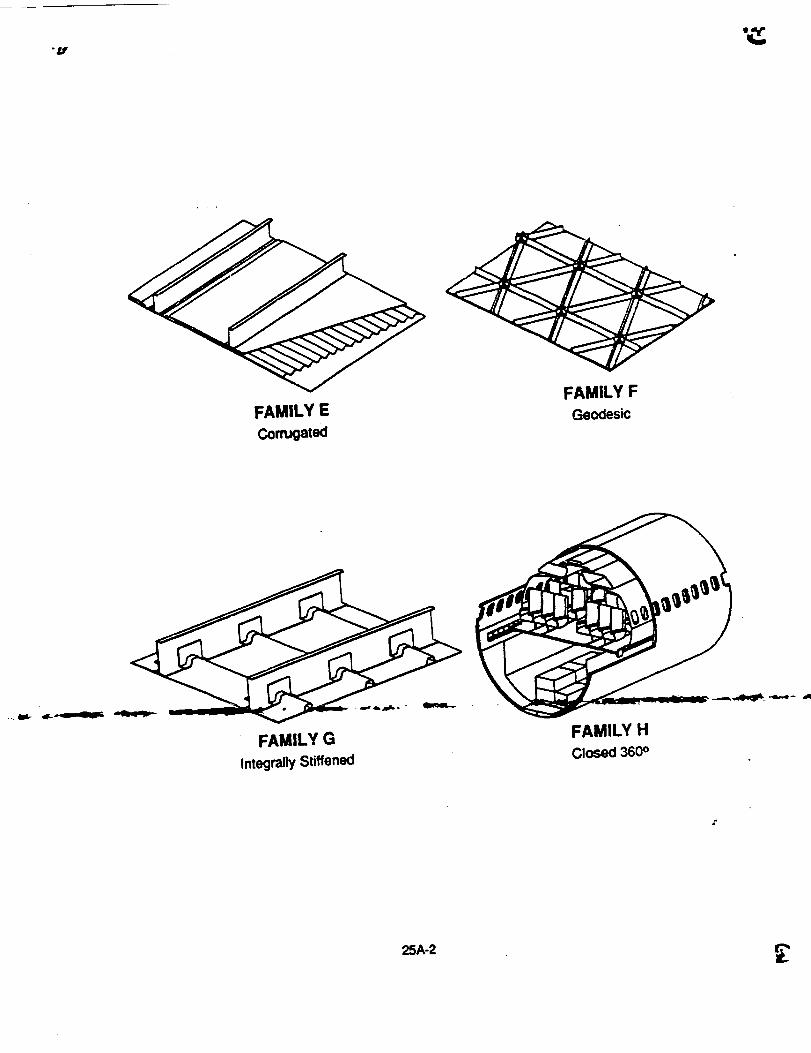
FAMILY E FAMILY F
Conugatod Geodesic
FAMILY G
Integrally Stiffened
FAMILY H
Closed 360 °
25A-2
__
APPENDIX B
KEEL DESIGN D1 AND D2 INTERCOSTAL DRAWING
p .lll=-- -1_-,- _.

APPENDIX C
KEEL DESIGN D1 CARGO FLOOR FRAME DRAWING

•- !
_UT
_oI
13DI "t"
I
LD _ .n
' I0m
¢.I!
Ii
I
_J
f
V
FOU)Om"
IU ? i
F IUL_I IP'
J
II
+4___
I-
_'gl"
0 tO
mm mmmmm mlm i _ _im im mm m mm
_m m umklmll J _ _ _ u ami_l atom
i_" r,sc..--'.--_m_lg
II

?
TC'_cI(-o _ 4j
ab'_/_olJI & .-q41
-411"
I
'A •
-I. O_:m,-2-,,1. 'f'J_4-5. al_
-!). OoP-I4INT1H_
.<_
i
...-I
7 '6'

6 I
-! _..4
m
4
6
duuml°mmm_mm m u4_mr m ummmm
m m_ImB I _ i _mmmm m _ _ma_umm o mml
I

• I .1
"__
FOl..X:lot_r_
almP _ g _ munpl mNll u _ Ii_lml 4_. _mm_m.
4 NINJ 4'm_,ll
f
'IB,,,E !
I
uq
_am
2
-L
_,. _2 !m N _ n _ II laid Ilia miamim i IIi ill lindiql iI _10 ill loll Ill m-- _ _ W nail i areal li_iml Iwm, m
f'l::}_ _" c

OOUT
• .w •
• Z 4,p
LaB •
• I,-- 0 •
• X •
,II 0 •
• :_..J -
• o _ J, :U I-- J-- kaJ
• 4L' r,_ Z _ •
! •
ell _' Z •
Z I-- k.., •
_.0
• 4k
• %. (D
C
a
I 11
,0,,
.....__ ,' i__f , ._-
1
12

,_ _o I
!
9
,,'!'Illi
I-_1I
°_
Ii
t._t MI r
I05sr iI, l"lill u_._lil_
IOIU£ I0(
.DOUT
STIF"r_,IE_ _ DIAGI_I4
Ii_t_._
"_1
1i
ql. lO
___J
<J! I
l IAgwl
IEFJclo
._-II
,1. I,oe es,|
IA9
)Be
_mj
I0
.ime_.ml m _lllllillllll ol) Imllilllll lip AlE Imm allle
mul_ml mm _11mm m.
r.... 6 I _"
9

I
Im
I;m.I-_3G
\\
J
I
I I
k
1A?
ILIll
.___l&
q_t_
IY
IA.3
iii iiiii_ii_ a Ii IoolH|iiiiiii_iii_i _iii ii iii_i_
6

,4
r i
I
__ ! -Ill I II tI II I
/ _/" I N I
' 11/11 , m iI
! I ! III/
I ii I I l I
-. . _ I 11/ / I l I
-- ' _l " - ///,I _/ 11 ''l #
I | I
I I I
i
i
io_ j
- --t__1.mr

3 _ 2 l iq m ,IlUnINIIB Imalqm _W Ill luamm i
J alUm,IIIM, O iI / ii ii*m al imll¢ll Ill m Ilmnl,amIVlIB a_ll
Ipl. _ o aumnwlll.lmll uuuuple i1_1 rome iml 0mlUlNIlil liumm'. 21N_ l
FOLDOU';" R_I_ME
uu._, ..
- ul.i -T
,t li_+U +o ,- - -
4- * ÷
i I
!
I
J
I)
h II al, II, I
c:]:> _,,¢,1_,¢1l._ ,_."Jl,la,¢'l
i
roll _ ,IpN voIN _ aiNul _ i, • _ 1,1_. M-1111.1_i _ ¢¢v N i m I_BW IB MII_,
_'_l__.__..,.P_Wlm Ill m.
e mmn_.o,_, Utae f aJq_l., qp_8 m_ N JJI" _ _ I
":" """ " I°'_" _-J;-.---t ---_-,-- 1

APPENDIX D
KEEL DESIGN D2 FRAME DETAILS DRAWING
r--!
('3
flu
lid
E
8 I 7
T1
I
tcsimrlrll_ _r'_ i1-
.14m
IC3_llUi.._at

6
_ _ anNID'
1 5
F/
qll
_ _ _ wlpllallU IWJl _ in; IlUNIO_ _, I0 unllm_ mud _ U aummD
Ila_¢"- r,¢,_._ I_1 1
I 5 I
.1
JJ
4 I 3 9 2
iiw IIINI ii m i1_1_ iII IIIII _ i IIIIII. _wlqill.lllMii m ql ilul Illllw
mu
lllll.l
L I(:>__ II. ill
,I,I m
iI,t=>
,,l,,
OLrl'AII. -I
4 I 3 0 2

IC3*v
_>
_>
2
m-
_OLDOUT FRNI
• -°
mmem
roll M W_ 4#.f.
-t_ _ aUtl_ _ MInE P _mg_ l_Ib_
250.-I
B
2 M I

APPENDIX E
KEEL DESIGN D2 CARGO FLOOR DETAILS DRAWING

\
i
C
!1
1!
8 9
IE
/.°
dL| air
rI
II.II IB"
1
I
L

1 s• 1
FOLDOUT
_ II I1 n II II II il II | ni ni i I I nn ill
I.el ,at
-- 7
aillm ailr g him m IIIIB m m auI II 1 IqI
I s 1 1

! 3 _ 2 .m _anani m I quirtI _
n • • • n n • n • • • n u • n . n n n • n . • • n :__::_: m'_ml _: _-_ __
4 FOLqU. gl
I
ClI_O i_uCX_ P -t
-T L__
- i
f
.... _.-. _-_ ._
i
!
I!i
OQ
L,_IL17
I.a .,"_ _ _,l I.ll
I"P
0 2
mUN_
It •mt
i
r
P
- _,--- .... ___. __ _.- - _......
%
!
/
#,,. ,
aE>i'_'="''"CZ:>_&11r_l_*A - w**'**
4".
f,
_~_ _ ,'

APPENDIX F
KEEL DESIGN C1 CARGO FLOOR DETAILS DRAWING

Fotoo_r
"r_
rU
C_A
c
I
L
tt
i
8
F_ &Ill W
I.W I_P
m
W i . i
L.tm IIPJ
(41,qV4 !
IIOLI1.101l
1J
t
It
tBI
_.M _ SEEI_
.IHI
Lc>(_I'AIL -4
8 l

FOLDOUT FRAME
'ILm ql"
f
!
t
F t.,lll IgP "-_
___.JIIIIIIIMI -- .. I,
tM Q4
104
I
..rl
t.In Lm
T_
6
miml mm_iNl_wmB i m m i m i li_l,i m m i _i qe_iqBuliwgmgo mM_tmm
I 5

mm _pNN immimp_mqo
I_+: _I ................... _ , • i__ _$ { ....
m_unmuummmmsmm|miimmmmmmi|mumi|mmmmmmI
_.---rr_ II 4 i 3 O

_g__t_t_._ _ nm _ aimlUel
n i m i FOLDOUI'
2SF-1
B|||H|BBB|nnU||
CE>IalfL__ m _m_
-R|_N e ,tOg n n

APPENDIX G
PICTORIAL OF ASSEMBLY OF KEEL DESIGNS DIA AND
DIBD

!2f_--1

\
LL
O
n-"
25G-2
\

WW
U.
o_Z,._I
w I--_._WO3
-- Z
OII1O
_G--.3

!
/
/
/
25G-4

.p -
J
25G-5
n
I It

°
ILlZ
njlLIIIILl
ooZ_W
k_
0..
7.
°
/
25G-7
25G-8

2SG-9
Z
0
0Z
Z0
Wco
Z
zm
0
c_
F-0z

,,_1LUZ
I:L._1LULUY
25G-10
LLI
25G-11

wZ
n.-Iww
25G-12
(
J

',ER SHIM
KEELINTERCOSTAL
/
ATCASAFT VIEW OF KEEL
INTERCOSTALINSTALLATION
CLOSE-UPSK-14
25G-14

25Gt15

CARGO FLOORBEAM STIFFENER
STRINGER CLIP65C35559-6 OR -5
ATCASINSTALLATION OF
LONG. STRINGERCLIP CLOSE-UP
SK-16
KEEL PANEL
SIDE PANEL
LONG. BLADE STRINGER
25G-16

iI
i
25G-17
25G-18

/
LU0
0Z
r
/
|
L.
rL
t!
if
r
25G-21

• il
I
I
25G-22

APPENDIX H
REVIEW DRAFT OF:
"NONLINEAR PROPERTIES OF METALLIC CELLULAR
MATERIALS WITH A NEGATIVE POISSON'S RATIO"
(

Nonlinear Properties of Metallic Cellular
with a Negative Poisson's Ratio
Materials
J.B. Chol', M.S., Graduate Student
and
R.S. Lakes§, Ph.D., Professor
§Deparlment of Mechanical Engineering"§Department of BiomedicalEngineering
§Center for LaserScienceand EngineeringUnive_ty of Iowa, Iowa City, IA 52242
Departmentof BiomedicalEngineeringUniversity of Iowa
iowa City, Iowa 52242
May 23,1991
25H-1

2
Abstract
NegativePoisson'sratiocopper foam was preparedand characterized
experimentally.Thetransformationintore-entrantfoamwasaccomplishedby applying
sequentialpermanentcompressionsabovethe yield point to achievea triaxlal
compression.ThePoisson'sratioofthere-entrantfoamdependedonstrainandattaineda
relativeminimumat strainsnearzero.Poisson'sratioas smallas -0.8 was achieved.
The strain dependence of propertiesoccurredover a narrower range of strain than in the
polymer foams studied earlier. Annealing of the foam resulted in a slightly greater
magnitude of negative Poisson'sra_ and greater toughnessat the expense of a decrease
in the Young'smodulus.
25H-2

jl.,
3
1. Introduction
Cellular solids are lightweight materials consistingof a network of solid ribs or
plates. Man-made cellular solids have been widely utilized in the form of structural
honeycombs (two dimensional cellular solids) in aircraft and in the form of foams
(three dimensional cellular solids) for packing, cushioning, energy absorption
applications, sandwich panel cores, structuralpurposes and thermal protection systems.
Natural materials such as wood, cancellous bone, coral and leaves have a cellular
structure. All these 'conventional' cellular materials have a convex cell shape and
exhibit a positive Poisson's ratio. Recently, isotropio foam structures with negative
Poisson's ratios have been fabricated by one of the authors[I]. The fabrication was
achieved through a transformationof the cell structurefrom a convex polyhedral shape
to a concave or "re-entrant" shape. Increase in some.material properties such as
flexural rigidity and plane strain fracture toughness was reported[I,2,3].
The range of Poisson'sratio for isotmpic matedal is -1 to 0.5, as demonstrated
by energy arguments[4]. Negative Poisson's ratios are rare but not unknown. Negative
Poisson's ratios have been reported in single crystal pydtes[5] and in some rocks[6].
Synthetic anisotropic microstructures['/] were found to give such an effect. One of the
authore[8] suggested that non-affine deformation kinematics are essential for the
produntlon of negative Poisson's ratios in isotropic materials. A recent study of
polymeric re-entrant foams with negative Poisson's ratio[9] reported other enhanced
material properties: an increase in the toughness, in the shear modulus and in the
resilience In the sense of a wide range of linear stress-strainbehavior. Conventional and
re-entrant polymer foams also differ in their stress strain behavior and deformation
(
25H-3

L
i
4
mechanism maps [9]. In copper foam an increase in the indentation resistance was
demonstrated experimentally [10], which is consistent with theory{Ill.
Mechanical properties of a conventional foam material depend on the physical
properties of the solid material making up the cell dbs, relative density (the ratio of
the bulk density of the foam matedal to the density of the solid from which It is made),
cell shape, cell size and loading conditions. The simplest and most comprehensive
treatment of conventional fGam properties is that of Gibson and Ashby [12], which
includes extensive comparisons between analytical results and experiment. In re-
entrant foam; relative density is increased and the cell size is reduced slightly by the
transformation process; the cell shape is dramatically altered. Mechanical behavior of a
re-enVant foam matedal differs from that of a conventional foam in ways not addressed
by existing theoretical treatments; most of the difference is attributed to the change in
cell shape.
In this study, the mechanical properties of beth conventional and re-entrant
copper foam matedais are examined at small strain by optical methods and at larger
strains by sefvohydraulic (MTS) machine tests.
2. Experimental procedures
2.1. Specimen preperation: optical study
A large block of copper foam (Astromet Corporation) with relative density
between 0.08 and 0.1 was cut into smaller 18 x 18 x 36 mm blocks; another large
with relative density 0.04 was cut into 25 x 25 x 50 mm blocks. Bar shaped specimens
were cut from these blocks using the procedure described below. The blocks were not
perfectly uniform: specimens of relative density of 0.04, 0.08, 0.09, 0.1 had deviations
of 12%, 6%, 5.5%, 5%, respectively in relative density.
25H-4

Blockspecimenswerecut witha highspeedsawto minimizesurfaceplastic
deformation.The foamwas thentransformedintoa re-entrantstructureby applyir_
smallsequentialincrements(lessthan 2% stra!:_)of plasticdeformationin three
orthogonaldirectionsusinga visefittedwithPMMA(Plexiglas®)endpiecesto provide
anevensurface.Thecompressedfoamswerecutagainintoslenderbars(approx.7 by 7
by 30 mm) following the above cutting method. The lengths of the cell ribs were
measured with a microscope in order to compare the cell size for each specimen.
The re-entrant foam specimens have irregular surfaces which were polished
with graded abrasives (silicon carbide grits 120, 320, 600 and 1000), under water
Irrigation, in order to obtain a smooth surface for optical tests. The water Irrigation
served to minimize t3mperature increases due to fdction and improved the surface
finish. High grinding speed and low pressure were used to avoid plastic deformation of
the surface. The finest polishing medium grains of 1000 mesh had a size of about 18
wn[13]. This provided sufficient smoothness to the surface so that the shadow moir_
method could be applied to measure deformation.
!
2.2. Specimen preparation - MTS machine test
Rectangular spedmens from a large block of initial relative density 0.08:1: 5%.
were made with volumetric compression ratio of 1.2.0, 2.5, 3.0, according to the ASTM
standard for subsize specimens[14] for both tension and compression tests. The
dimensions of the specimens were 6.4x6.4x25.4(mm) for tension, 19x19xg.5(mm)
for compression; the compression specimens were made shorter to prevent budding.
These specimens were porshed as _ above.
Specimen ends were cast in dental grade polymelhyl methac_late(PMMA) which
is much more dgid (E,,3GPa) than the copper foam (E-200MPa). This procedure
25H-5
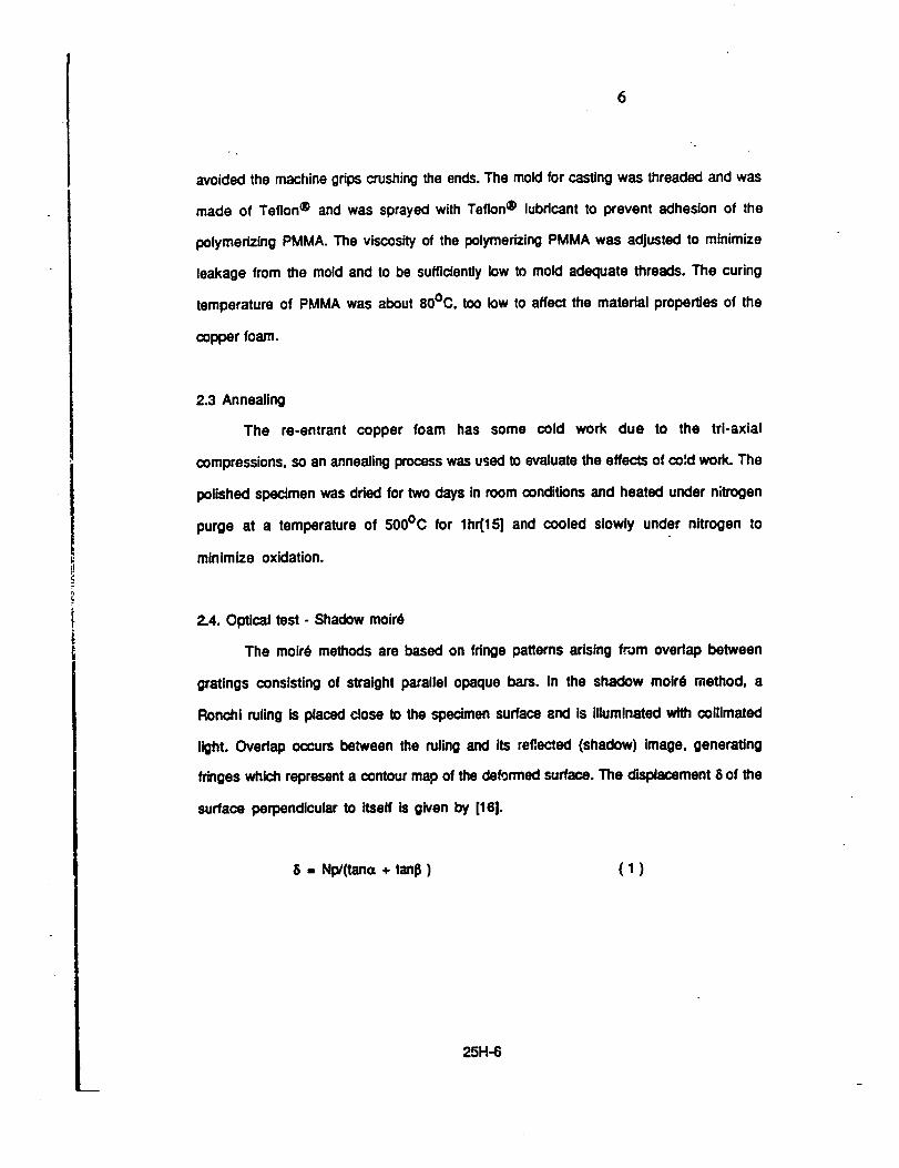
6
avoided the madline grips crushing the ends. The mold for casting was threaded and was
made of Teflon ® and was sprayed with Teflon ® lubricant to prevent adhesion of the
polymerizing PMMA. The viscosity of the polymerizing PMMA was adjusted to minimize
leakage from the mold and to be sufficiently low to mold adequate threads. The curing
temperature of PMMA was about 80°C, too low to affect the matedal properties of the
copper foam.
2.3 Annealing
The re-entrant copper foam has some cold work due to the trl-axtal
compressions, so an annealing process was used to evaluate the effects of co',d work. The
polished specimen was dried for two days in room conditions and heated under nitrogen
purge at a temperature of 500°C for lhr[15] and cooled slowly under nitrogen to
minimize oxidation.
2.4. Optical test - Shadow moir6
The moird methods are based on fdnge patterns arising from overlap between
gratings consisting of straight parallel opaque bars. In the shadow moir_ method, a
Ronchi ruling is placed close to the epedmen surface and is illuminated with collimated
light. Ovedap occurs between the ruling and its reflected (shadow) image, generating
fringes which represent a contour map of the deformed surface. The displacement 8 of the
surface perpendicular to itself is given by [16].
8 = Np/(tana + tanl3 ) (1)
25H-6

t
where N is the fringe order, p Is the pitch of the grating, ,_ is angle of the incident light
and 13is the viewing angle with respect to the normal to the grating.
Specimens of initial relative densities of 0.08,0.09 and 0.1 were used, however
conventional foam of initial relative density of 0.04 is was not used in the optical test
because of the poor fdnge pattern due to the large cell size.
Bending experiments were performed by applying known weights to an aluminum
arm cemented to the top end of a vertically oriented copper foam specimen; the lower end
was clamped. The aluminum arm was sufficiently long that specimen strain due to
bending substantially exceeded compressional strain, approximating 'pure' bending. The
Young's modulus E and Poisson's ratio v were extracted from the displacement field by
first using simple beam theory to obtain an approximate val,;9 for E from the end
defleclJon 6:
6 - ML2/2Ei ( 2 )
where M is the bending moment, L is length, and I is the area moment of inertia. Then
the three dimensional solution was used to infer v and obtain a corrected value for E:
5 - ML 2 ( z2 + vx 2 - vy 2 )/2El (3)
in which z is a longitudinal coordinate along the length of the bar, x is a lateral
coordinate, and y is a transverse coordinate. The con'ec_n to E was small in all cases.
Positive Poisson's ratios give dse to hyperbolic fdnge contours, and negative Poisson's
ratios give dee to elliptic contours. In either case the Poisson's ratio was found from the
observed shape of the contours.
In this experiment, the grating was located a small distance, within a millimeter,
away from the specimen, parallel to the surface and odantad so that no fdnge pattern
occurred. Light from a mercury vapor lamp was collimated by a lens and directed upon
the grating at an angle 48 ° from the normal to the grating plane; the viewing angle was
25H-7

8
19 o. A 300 linetinch (11.8 line/ram) grating was used for determining the elastic
modulus and a 1000 line/inch (39.4 line/mm) grating for obtaining the Poisson's
ratio, since the latter was too sensitive for ready determination of fringe order at the
specimen end. For Poisson's ratio determination, the grating was tilted so that the center
of the fringe pattern appeared near the center of the bar. Measurements were performed
at a specimen surface strain of 0.05% to 0.1%. Theoretical contour lines based on
equation (3) were prepared for a variety of Poisson's ratio were drawn with an Apollo
computer using 'Promatlab' graphics software to facilitate the analysis of tha observed
fringe patterns appearing on the specimen surface.
2.5. MTS machine test
A servohydraulic testing machine (MTS corp) with a 2.5 kN load cell was used to
apply loads for the characterization of nonlinear properties of the foams. All t.'-e
experiments were performed at equal strain rates of 0.006 sec -1 . To determine lateral
deformation for the purpose of determining Poisson's ratio, dial gages (No. 25-109,
Starrett company, resolution 1.2 p.m, range 0.38 ram)were applied to each lateral
surface near the center portion of the specimen. A fiat tip was used in contact with the
spedmen in the case of lateral bulging, while a round one was used to evaluate lateral
contraction. A universal joint was _sed if'. ;he te_!on test and a small ball socket joint
was used in the compression test to assure alignment. In compression tests, Teflon tape
was used between the specimen and the loading surface to minimize the friction force on
the contact surfaces.
25H-8

_
3. Results and Discussion
In the conventional copper foam, the moird fdnge patterns were observed to b_
hyperbolas corresponding to a positive Poisson's ratio. Accuracy in the Poisson's ratio
determination was limited to ¢0.1 by uncertainty (about :1:5%)in measuring the slope
of the asymptote. For homogeneous materials, accuracy could be Improved by increasing
the strain hence the fringe density; however in these materials the fringes became
blurred beyond a certain strain[17]. In the re-entrant copper foams, the moir6 fringes
had elliptical contours corresponding to a negative Poisson's ratio. It was possible to
achieve better accuracy in this case as a result of the different fdnge shape and the
greater compliance of the transformed material.
Fig. 1 and 2 show optically determined Poisson's ratio at small strain as it
depends on the initial and final relative densities. The Poisson's ratio of conventional
foam with initial relative density of 0.09 is 0.2 ¢0.1. In the re-entrant foam, the
smallest Poisson's ratio observed was -0.8 ¢0.05 at a strain of 0.1%; the permanent
volumetric compression ratio was 2.13 and the Initial relative density was 0.1.
The negative Poisson's ratio of re.entrant foam attains a minimum for an optimal
value of permanent volumetric compression ratio; the optimal compression is smaller
for higher values of Initial relative density, as shown in Fig. 1. For copper foam with
Initial relative density of 0.04 the optimal compression ratio, 3.6, is comparable to that
of the polymer foams, 3.3 to 3.7, which have a similar relative density of 0.03. This
con'_oondence between two different metedaissuggests a geometrical cause associated
with the cell structure. For example, the optimum volumetric compression ratio arises
in part from the fact that too much compression causes the dbs to come in contact,
which hinders the unfolding which gives dse to the negative Poisson's ratio. In such a
simple view, one would expect the optimum to occur for a particular final relative
25H-9

NIP1I I_
10
density (determined as the product of the Initial relative density and the volumetric
compression ratio). Fig. 2, however, shows the optimumto depend on both the initial and
final relative densities, so the above interpretationis incomplete.
The elastic modulus decreases monotonically with permanent volumetric
compression as shown in Fig. 3, so that re-entrant copper foam is less stiff than the
conventional foam from which it was derived. Polymer foams behaved similarly, except
that for sufficiently large permanent volumetric compression, the stiffness began to
increase again.
The effect of annealing on the stress-strein r?latlonships for foams with
volumetric compression ratios of t, 2.0, 2.5, 3.0 is shown in Fig. 4. In tension, most of
the specimens failed near the cast polymer end piece due to stress concentration;the end
points on the tensikJside of the graphs representthis fracture. In compression, the tests
were terminated at the beginning of unstable compression due to buckling. The
conventional foam has some strain-hardeningtendency, but the re-entrant foam does not
exhibit this effect, thus, the latter can be modeled as a elastic-perfectly plastic
material. In both tension and compression, the con,:gntlonal and re-entrant foams
exhibit a rather long plateau above the proportionalIlmiL This behavior is attributed to
the plastic hinge formation of cell n'bs which occurs when the moment exerted on the
cell dbs exceed the fully plastic momenL By contrast, the fracture behavior of both
conventional and re-entrant copper foam in tension was brittle-like: failure occurred
abruptly without necking or ¢_rawing.The foams were bdttle even though the solid
copper from which the foam was made is ductile;such behavior has been observed in
other foams and has been analyzed in view of the alignment of cell dbs which occurs
under tension [12].
251-1-10

(
11
As for the compressive properties, errors can arise due to the effect of friction
with the loading surface combined with the Poissoneffect. An apparent yield stress
¢ry,appcan be expressed [18]in terms of the true yield stress for a spedmen witha ratio
of 2:1 in width to height as Gy,app-Gy, true(l+m ), where m is the friction ¢oeffident.
Since m is less than 0.1 for copper and Teflon, the maximum experimental deviation
through the whole load historydue to the frio_onforce is within 10%.
For the conventional copper foams the propertlssin tension and compression are
similar, as seen in Fig. 4. Young's modulus and the ultimate strength are lower by about
33% and 25%, respectively, for annealed material. The inset graph shows that the
foams are nonlinear even for strains below 1%; by contrast to the polymer foams
studied earlier. The difference adses from the yield of the ribs in copper foam at small
strain. The m-entrant spedmens as shown in Fig. 4 show very dissimilar properties in
tension and compression. Increase in the permanent volumetric compression ratio
results in reduced tensile stiffnessand Increased compressive saffness,as seen in Fig. 5
which shows the effective Young's modulusat 0.5% strain as it depends upon permanent
volumetric compression ratio. As for ultimate strength, it is reduced by about 15% in
both tensionand compmsdon by the annealingWocsss.
The experiments disciosad that the toughness, defined as _e energy per unit
volume to fracture, of the re-entrant foam compared to that of conventional foam,
inc_asad by factors of 1.4, 1.5, 1.7 with increases of volumetric compression ratio of
2.0, 2.5, 3.0, respectively. Annealing effects can further increase the toughness. This
effect was most evident at a volumeffio compression ratio of 2.0, as shown in Fig. 6.
However, the annealed m-antrant foams at a volumetriccompressionratio of 2.5 did not
show as much Increase, and the toughnessactuallydecreased in the foam at a volume0tc
compression ratio of 3.0. In case of an elaatomedcfoam such as polyurethanefoam, the
25H-11

12
experimentalresultsshowedincreasesby factorsof 1.7,2.1, 2.3, 2.6, 3.2 in the
toughnessof the re-entrantfoamcomparedto that of the conventional foam, at
volumetric compression ratios of 2.0, 2.8, 3.2, 3.7, 4.2, respectively[9]. Elastomertc
foam (which can be deformed at large strain)exhibiteda somewhat greater toughness
increase with re-entrant transformation in comparison to copper foam (which is
elasto-plastic).
The Poisson's ratio of the conventional foam shows highly nonlinear dependence
upon the strain, as shown in Fig. 7. The Poisson'sratiosof the conventional copper foam
are near 0.35 for small strain and approach 0.5 in tension and 0 in compression;
similar behavior was observed in conventional polymer foam {9]. This approach of
Poisson's ratio to zero at large strain In compression also agrees with other results:
Poisson's ratio for the plastic compression of foam matedal was typically 0.03-
0.05119,20] and Poleson's ratio beyond the yield point was 0.04 {21] in compression.
As for small-strain behavior of conventional foam, a strong dependence of
Poisson'sratioon the bulk density at a strain of not more than 0.5% was suggested [22].
Other authors showed a constant Poisson's ratio of 0.33 [12,23,24] or 0.23 [25]
Independent of relative density. Even though the cell morphology changes with the
relative density [25] any effect may be difficult to extract from the considerable scatter
in experimental values for Poisson's ratio [12]. The density changes In the re-entrant
foam are accompanied by cell shape changes, so the above considerations are not
applicable.
Annealed specimens gave a slightly better negative effect in the Poisson's ratio
(Fig. 7,8,9) at the expense of a decrease in the Young's modulus for each volumetric
compressionratio. The lowest Poisson's ratio obtained in this mechanical testing (MTS)
experiment was -0.49 at a strain of 0.2% as indicated in Fig. 8. In comparison, a
25H-12

13
Poisson'sratioof -0.6:L-0.05wasdeterminedopticallyat a strainof 0.1%for specimens
havingthesameinitialrelativedensity of 0.08 and the same volumetric compression
ratio of 2.5. A minimum Poisson's ratio of -0.8¢0.05 was determined op_cally at a
strain of 0.1% for a different specimen as described above. Fdis eL al. [3] obtained a
minimum Potsson's ratio of -0.39 at a compressive strain of 0.013 in mechanical tests
on copper foam with a permanent volumetflc compression ratio of 2.0 and a relative
density of 0.053. The difference may be attributed to the highly nonlinear behavior of
the metal foam as indicated by the cusp in Poisson's ratio vs strain. This contrasts with
the polymericfoam which exhibited a smootherdependence of Poisson's ratio upon slrein
and which exhibited a broader minimum in Poisson's ratio vs strain, in comparison with
the metal foams. The difference in behavior between the metal and polymer foams is
attributedto the fact that the dbs of the copper foam can yield and form plastic hinges at
relatively small strain, in contrast to the polymer which is an elastomer. The
nonlinearities in compression are attdbutad in part to regions of contact between cell
dbs in the re-entrant foam; no such contacts occur in the conventionaJfoam (Fig. 10).
4. Conclusions
1. The Poisson's ratio of both conventional and re-enVant foam,depends on sualn,
Poisson's ratio of rHntrant foam attains a relative minimum as small as -0.8 for zero
strain.
2. Optimum permanent compression to achieve the best negative Poisson's ratio
depends on the initial foam relative density: higher density foam requires less
compression for transforma*Jon.This optimum appears to have a purely geometriceJ
origin, since the same value was observed for metal and polymer foam of the same
relative density.
25H-13

14
3. The re-entrant copper foam in compressiondoes not exhibit strain han:lening.
4. The toughness of the re-enCant foam increases with volumetric compression
ratio and annealing effects further increase the tougl_ness.
Acknowledgment
Support of this research by the NSF and by the NASA/Boeing ATCAS program
under contract #NAS1-18889, and by a University Faculty Scholar Award (to RSL) is
gratefully acknowledged.
25H-14

15
i, °
/!, !
.p
(
5. References
1. R.S. Lakes, Science, 235 (1987) 1038
2. R.S. Lakes, Science, 238 (1987) 551
3. E.A. Fdis, R. S. Lakes and J. B. Park, J. Mat. Sd., 23 (1988) 4406
4. Y.C. Fung, "Foundation of Solid Mechanics" (Prentice-Hall c.ngiewood,
NJ, (1968) p.353
5. A. F_ H. Love, in "ATrea_se on the MathematicalTheory of Elasticity"
(Dover Pub., NY, 1944) p.163
6. O.G. Ingles, I. K. Lee, R. C. Nell, Rock Mechanics, 5 (1973) 203
7. K.E. Evans, B. Caddock, J. Phys. D: Appl. Phys., 22 (1989) 1883
8. R.S. Lakes, J. Mat. Soi.,26 (1991) 2287
9. J.B. Choi, R. S. Lakes, J. MaL Sci., submitted
10. K. F_Jmsand R. S. Lakes, in preparation
1 1. S.P. Timoshenkoand J. N. Goodler, "Theory of Elas_ (McGraw-
HHI, NY, 1969)
12. L J. Gibson, M. F. Ashby, "Cellular Solids" (Pergamon Press, 1988)
13. L E. Samuels, in "MetaliographicPolishingby Mechanical Methods"
(American Society for Metals,1982) p 80-81
14. "Annual Book of ASTM Standards" (Designatfon:ES-85b,1986)
1 5. "Metal Handbook, Heat treating,cleaning & Finishing" (American Sodaty for
Metals) p 285
16. A.S. Kobayashi, in "Manual of EngineeringStress Analysis" (Prentice Hall,
1978) p 62-63
17. C.P. Chan and R. S. Lakes,"Holographicstudyof conventionaland negative
Poisson's ratio metallic foams: elasticity, yield, and micro-deformation',
25H-15

16
J. Materials _,Ccience, in press.
18. R. Hill, in "The Mathematical Theory of Plasticity" (Oxford University
Press,1983) p 236
19. M.C. Shaw and T. Sara, Int. J. Mech. Scl., 8 (1966) 469
20. J.A. Rinde, J. Appl. Polym. Sd., 14 (1970) 1913
21. M. Wilsea, K. L Johnson and M. F. Ashby, Int. J. Mech. Sd., 17 (1975)
457
22. A.G. Demant'ev, P. I. Seliverstov and O. G. Tarakanov, Mekhan. Polim., No.
1 (1973) 45
23. A.N. Gent and A. G. Thomas, Rubb. Chem. Tech., 36 (1963) 597
24. J.M. Lederman, J. A_opl. Polim. Sd., 15 (1971) 693
25. A. Mclntyre, G. E. Anderton, Polimer 20 (1979) 247
25H-16

(
17
r
t
f.
List of Figures
Fig. 1
,0.09; # ,0.08; a ,0.04
Fig. 2 Polsson's ra_o vs final relative density; Initial relative density; _ ,0.1;
't ,o.og; • ,0.08; a ,0.04
Fig. 3 Young's modulus as it depends upon initial relative density and upon volumetric
compression ratio; Initial relative density; I_ ,0.1; _ ,0.09; X ,0.08; o ,0.C4
Fig. 4 Stress- strain relationships for conventional and m-entrant foams. Initial
relative density:.0.08. Solidsymbols:annealed. Open symbols:not annealed.
I_ Squares: conventional foam, volumetriccompression 1.
A Tdangles: re-entrant foam, volumetric compression 2.0.
0 Circles: re-entrant foam, volumetflc compression 2.5.
0 Diamonds: re-entrant foam, volumetric compression 2.0.
Fig. 5 Young's modulus vs permanent volumetric compression ratio for annealed and non
annealed copperfoam at a s_'ainof 0.5%; _ ,non-annealed; • ,annealed
Fig. 6 Toughness vs permanent volumetric compression of the conventional and re-
entrant copperfoams: e, non-annealed; IF, annealed
Fig. 7 Potsson's ratio vs longitudinal strain for copper foam, initial reiaUve density:
0.08. Solid t, conventional foam; O, re-entrant foam, not annealed, volumetric
compression ratio of 2.0
Fig. 8 Poissons ratio vs longitudinal strain for volumetric comprsssion ratio of 2.5,
Initial re_stivedensity: 0.08; _ ,non-annealed; ¢I ,annealed; c] _optlcal result
Polsson's ratio vs volumetric compression ratio, Initial relative density; El ,0.1;
25H-17
-(
18
Fig. 9 Poisson's ratio vs longitudinal strain for volumetric compression ratio of 3.0,
Initial relative density: 0.08; o ,non.annealed; • ,annealed
Fig. 10 Scanning electron micrographs of conventional copper foam (top), relaIive
density 0.08; re-entrant copper foam (bottom) initla; relative density 0.03,
volumetric compression ratio 2.5.
L 251-I-18

(
0
m
0Wm
0L
O.4
-0.0
-O.2
-0.4
-0.6
-0.8
-1.0
Volumetric Compression Ratio
,C5H-19

_'v ' " ........ 1
A
m-,s
m
"00
.=
C
0),,,
150
_00
5O
\
I
'_ 3 4
Volumetric Compression Ratio
25H-21
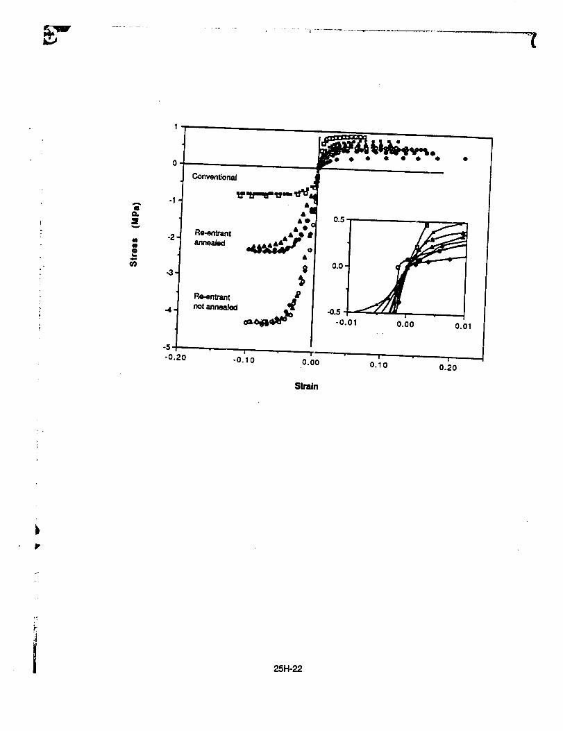
A
qa.
¢8m
w
u_
-5-0.20
Re-entrantnot8nnealed
0.01
-0.10 0.00
Slmln
0.10 0.20
bP
25H-22

i,
3OO
I A
mQ.
V
R
1=0
Z
oI=1I=30
>-
2OO
100-
0
1.0
Tension
Volumetric Compression Ratio
25H-23

100
go
con_
ol4)
,C
0i--
80
70
6O
SO
4O
1 2 3 4
Volumetric Compression Ratio
25H-24

I
0romp9rob
m
.m
0
m
0n_
-0.05 0.00 0.05 O. 10 O. 15
Longitudinal Strain
LL
25H-25

0m
(Be"
eli
0MM
m
0n_
-0.1
-0.8
-O.7
-0.10 -0 05 0.00 0.05 0.10 0.15
Longitudinal Strain
25H-26
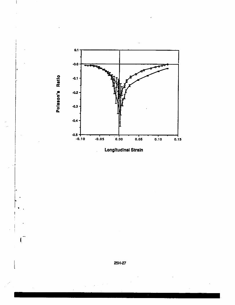
r*i
0m
m
omiI
on_
0.1
-0.0
,,0.3'
-O.4
-0.5
-0.10 -0.05 0.00 0.0G 0.10
Longitudinal Strain
0.15
4
t 25H-27

25H-28

![Catlog12siglos Muriel.indd 47 2/6/09 16:06:31 - … · Liliana [Texto impreso] : poema. – Vilanova i la Geltrú : Oliva, 1907 Madrid, Biblioteca Nacional de España, BA/7769 Apeles](https://img.dokumen.tips/doc/110x75/5baff17509d3f263638d9a32/catlog12siglos-47-2609-160631-liliana-texto-impreso-poema-vilanova.jpg)


