Embed Size (px)
Citation preview

2019-09-05
1
Kangwon National University
Prof. B. H. Kim Adv. Solid Modelling
Advanced Solid Modeling
Ch 1 3D CAD의 개요
Department ofMechatronics EngineeRing
Kangwon National University
Prof. B. H. Kim
3D CAD & CAM
In CAD
In CAM
Adv. Solid Modelling

2019-09-05
2
Kangwon National University
Prof. B. H. Kim
3D CAD & CAE
from [Crash FE Simulation in the Design Process ‐ Theory and Application, By S. Roth, et al.]
Adv. Solid Modelling
Kangwon National University
Prof. B. H. Kim
3D CAD & RP https://blogs.windows.com
Mesh Review Mesh Fixing
Adv. Solid Modelling

2019-09-05
3
Kangwon National University
Prof. B. H. Kim
3D CAD & Concurrent Eng.
Eng. Drawing
CAA
CAE
CAM
Solid Models
http://www.necova.gr
Adv. Solid Modelling
Kangwon National University
Prof. B. H. Kim
3D CAD & Reverse Eng.
Adv. Solid Modelling

2019-09-05
4
Kangwon National University
Prof. B. H. Kim
3D CAD & Digital Twins
https://dupress.deloitte.com
Adv. Solid Modelling
Kangwon National University
Prof. B. H. Kim CAD/CAM

2019-09-05
5
Kangwon National University
Prof. B. H. Kim
Wire Frame Model
• Definition of wire frame model– One of the visual presentations of a three-dimensional (3D)
or physical object used in 3D computer graphics.– It is created by connecting an object's constituent vertices
using straight lines or curves.
Topology Example
Adv. Solid Modelling
Kangwon National University
Prof. B. H. Kim
Exercise
• See Display style on Head-up Tool bar in Graphicarea of Solidworks
• Shaded with edges (Solid model + Wireframe)
• Shaded (Solid model)
• Hidden Line Removed (Surface model or Wireframe model)
• Hidden Line Visible (Wireframe model)
• Wireframe Model
• Weldments Exercise (using 3D sketch)– At first Download Weldments Contents @ Design Library
• Download (Control+Click) ISO files to Weldment profile folder.– Draw Simple table using 3D sketch (How to fully define the
entities?)
Adv. Solid Modelling

2019-09-05
6
Kangwon National University
Prof. B. H. Kim CAD/CAM
Kangwon National University
Prof. B. H. Kim
What is parametric ?
• Define a parameter space– 1D for curves ex) 0 ≤ t ≤ 1, - ≤ t ≤ ≤ t ≤ – 2D for surfaces
• Define a mapping from parameter space to3D points– A function that takes parameter values and gives back 3D
points– The result is a parametric curve or surface
Adv. Solid Modelling

2019-09-05
7
Kangwon National University
Prof. B. H. Kim
Parametric curves
• We have seen the parametric form for a line:
• Note that x, y and z are each given by anequation that involves:– The parameter t– Some user specified control points, x0 and x1
• This is an example of a parametric curve
Adv. Solid Modelling
Kangwon National University
Prof. B. H. Kim
Why parametric ?
• Problems of analytical or nonparametricrepresentations of curves– unsuitable for use in CAD applications– Dependent on the choice of coordinate system– unsuitable for geometric transformations, such as
rotations, translations, and scaling.– The implicit representation is
awkward for generatingpoints on a curve becausex values may be chosenwhich do not actually lie onthe curve.
- ex) the circle fails the verticalline test
• Derivative of Implicit f’n- Circle: x2 + y2 = 1- Chain rule- 2xdx + 2ydy = 0 dy/dx = -x/y• Derivative of parametric f’n- Circle: r() = [Rcos Rsin]
(0 ≤ ≤ 2)- dr()/d = [-Rsin Rcos]
∴ 1) free from coordinate,2) free form x, y, z correlation (1
input 2 output)3) easy to get derivtives
• Derivative of Implicit f’n- Circle: x2 + y2 = 1- Chain rule- 2xdx + 2ydy = 0 dy/dx = -x/y• Derivative of parametric f’n- Circle: r() = [Rcos Rsin]
(0 ≤ ≤ 2)- dr()/d = [-Rsin Rcos]
∴ 1) free from coordinate,2) free form x, y, z correlation (1
input 2 output)3) easy to get derivtives
Mathematics
Adv. Solid Modelling

2019-09-05
8
Kangwon National University
Prof. B. H. Kim
Parametric Curve Examples
Adv. Solid Modelling
Kangwon National University
Prof. B. H. Kim
Surface model
• (free form) Surface model– It is used in CAD and other computer graphics software to
describe the skin of a 3D geometric element.– They are used to describe forms such as turbine blades, car
bodies and boat hulls.
Adv. Solid Modelling

2019-09-05
9
Kangwon National University
Prof. B. H. Kim
Surface model
• Parametric descriptionof a surface patch
• plane
Adv. Solid Modelling
Kangwon National University
Prof. B. H. Kim
Surface model
•Ruled surfaces- In geometry, a surface S is ruled (alsocalled a scroll) if through every point of Sthere is a straight line that lies on S.
- A ruled surface can always be described(at least locally) as the set of points sweptby a moving straight line. (e.g.: a cone)
- See examples. TAB surfaces. Developable surfaces: G. Curvature =0
Helicoid
Hyperboloid
Hyperbolic‐paraboloid
Adv. Solid Modelling

2019-09-05
10
Kangwon National University
Prof. B. H. Kim
Surface model
Directrix(준선)
Ruling vector(지배선/괘선)
• Ruled surfaces
Adv. Solid Modelling
Kangwon National University
Prof. B. H. Kim
Ruled surfaces
•Bi-Cubic rule surfaces (Coons patch)– Addition of two ruled surfaces
Linear vs Bi‐cubic
Adv. Solid Modelling
2019-09-05
11
Kangwon National University
Prof. B. H. Kim
Surface model
•
•
Adv. Solid Modelling
Kangwon National University
Prof. B. H. Kim CAD/CAM
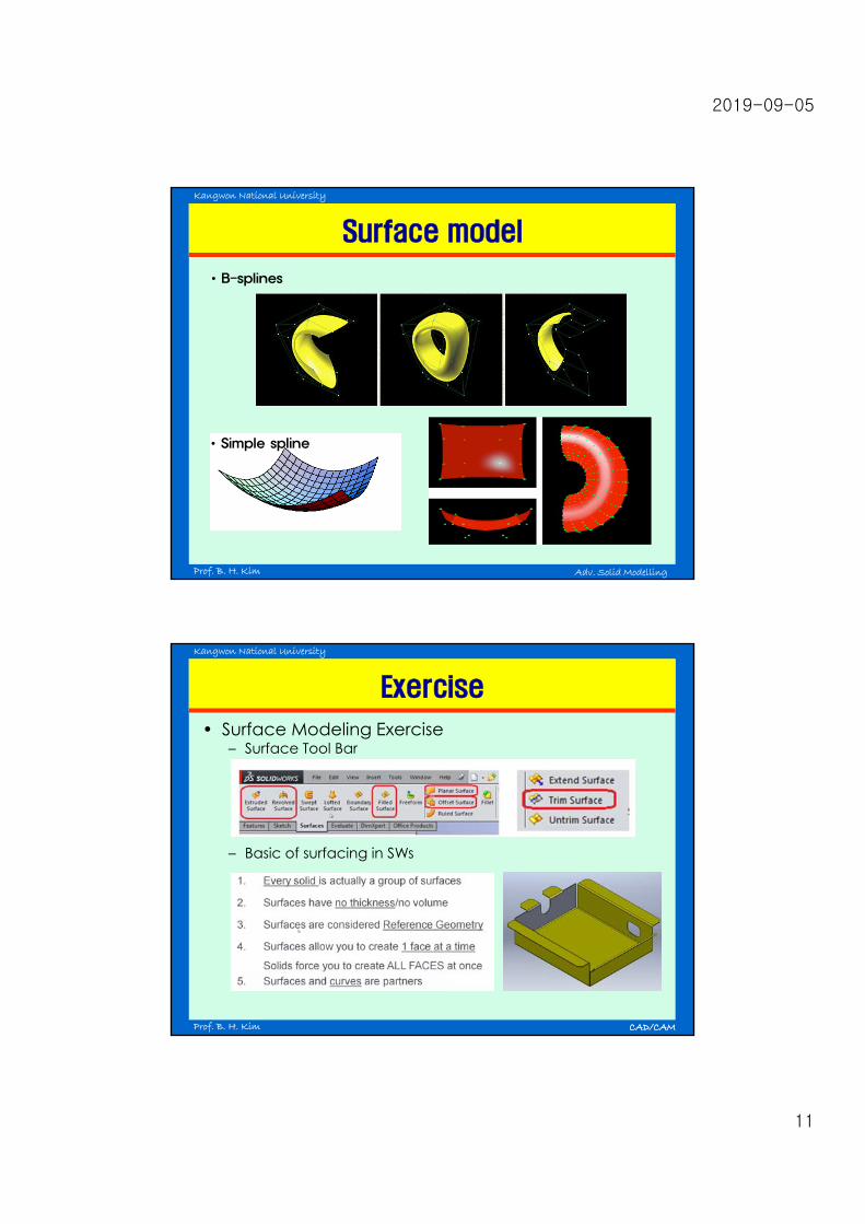
Exercise
CAD/CAM
• Surface Modeling Exercise– Surface Tool Bar
– Basic of surfacing in SWs

2019-09-05
12
Kangwon National University
Prof. B. H. Kim CAD/CAM
Ridiculous Design Examples
• Distance from Extruded Hole toPart Edge: If a(an) (extruded)hole is too close to the partedge, it can lead todeformation or tearing of themetal.
Kangwon National University
Prof. B. H. Kim CAD/CAM
Ridiculous Design Examples
• Distance Between Extruded Holes
• Distance Between Extruded Hole toBend

2019-09-05
13
Kangwon National University
Prof. B. H. Kim CAD/CAM
Ridiculous Design Examples
• Too small hole diameter Hole ≥ Sheet metal t
• Too small bend radius Min. R ≥ Sheet metal t
• Improper notch feature Width ≥ 1.5 times of t Length ≥ 5 times of t Corner R ≥ 0.5 times of t
Kangwon National University
Prof. B. H. Kim CAD/CAM

2019-09-05
14
Kangwon National University
Prof. B. H. Kim CAD/CAM
What is Solid Modeling?
• Definitions– A consistent set of principles for mathematical and
computer modeling of three-dimensional solids.– Solid modeling is distinguished from related areas of
geometric modeling and computer graphics by itsemphasis on physical fidelity.
Kangwon National University
Prof. B. H. Kim CAD/CAM
What is Solid Modeling?
• 'Solid Modeling' is a method used to design parts by combiningvarious 'solid objects' into a single three-dimensional (3D) part design.
• Originally, solid modelers were based on solid objects being formedby primitive shapes such as a cube, rectangular prism, cone, torus,cylinder, sphere, wedge (rectangular prism) and so on.
• Because of their limited use, some solid modelers have abandonedthe primitive shapes altogether in favor of predefined library solidobjects. 'Stock' library objects provide the designer with a similarshape to begin the design with, eliminating some of the initialtedious design work.☞ Let’s Check the Tool Box (Use read only)
• The real power of a solid modeling application is how it can take thesolid objects and combine them together by intersecting, joining, orsubtracting the objects from one another to create the desiredresulting shapes.
• Since the solid modeler's database knows so much about the entirepart model, it can perform functions virtually impossible with surfacemodeling. For example you can 'fillet’ all the adjacent edges of aface to other faces in a single command. Another popular exampleis the 'shell' function of solid modelers. This allows you to define aconstant wall thickness for the entire model with a simple task with asingle command.

2019-09-05
15
Kangwon National University
Prof. B. H. Kim CAD/CAM
Primitives
Kangwon National University
Prof. B. H. Kim CAD/CAM
Exercise
• Cube & Thin Features
• Merge
Mass = 1461gMass = 1612g

2019-09-05
16
Kangwon National University
Prof. B. H. Kim CAD/CAM
Exercise
• Wedge by Cut with Surface
• Repairing sketch (Tools > Sketch Tools > Repair Sketch)
Up to vertexSurface/Thick
Kangwon National University
Prof. B. H. Kim CAD/CAM
Solid modeling techniques
• Parameterized Primitive Instancing • Spatial Occupancy Enumeration (SOE)• Cell Decomposition• Constructive Solid Geometry (CSG)• Boundary Representation (B-Rep)

2019-09-05
17
Kangwon National University
Prof. B. H. Kim CAD/CAM
Parameterized primitive instancing
• Composite drawing with simple shapes (primitives)• Representing families of objects (GT)• Applying scaling transformation to the composite
drawing/primitive• A solid is specified by indicating the family to which
it belongs and a limited set of parameter values• Restricted range of objects (predefined families)
Kangwon National University
Prof. B. H. Kim CAD/CAM
Spatial Occupancy Enumeration (SOE)
• Subdivides 3-D space into volumes (spatial cells) and classifiesthese volumes as empty, full, or partially full of the solid
• An object is specified by listing all the spatial cells it occupies• Accuracy necessitates small cells
enormous memory requirements• These can be indexed using octrees
0
1ijkv
solidotherwise
CGS to Cell

2019-09-05
18
Kangwon National University
Prof. B. H. Kim CAD/CAM
Octrees
Kangwon National University
Prof. B. H. Kim CAD/CAM
Cell decomposition
• A general class of SOE - similar to SOE butsubdivides the object
• Solid is decomposed into simple solid cells with noholes and certain boundary matching conditions
• Much less memory than SOE

2019-09-05
19
Kangwon National University
Prof. B. H. Kim CAD/CAM
Constructive Solid Geometry (CSG)
• Using unbounded half space and primitives– Unbounded half space: Using for generation solid primitive– Solid primitive: block, sphere, cone, cylinder, torus, wedge...
• Boolean operation• Simple and obvious• No unique solution lots of CSG tree• Dangling Edges
Kangwon National University
Prof. B. H. Kim CAD/CAM
CSG Boolean operation (pp28~31)
Subtract
Intersect Primitives Union
Union Intersect Subtract
http://www.youtube.com/watch?v=dCckl1gw8wo
2019-09-05
20
Kangwon National University
Prof. B. H. Kim CAD/CAM
Boundary representation(pp31~33)
• Suitable to NC• Unique solution• Hard to construct data base
Generate the shape by CSG Boundary evaluation Construct B-rep database
• Euler’s rule
Kangwon National University
Prof. B. H. Kim CAD/CAM
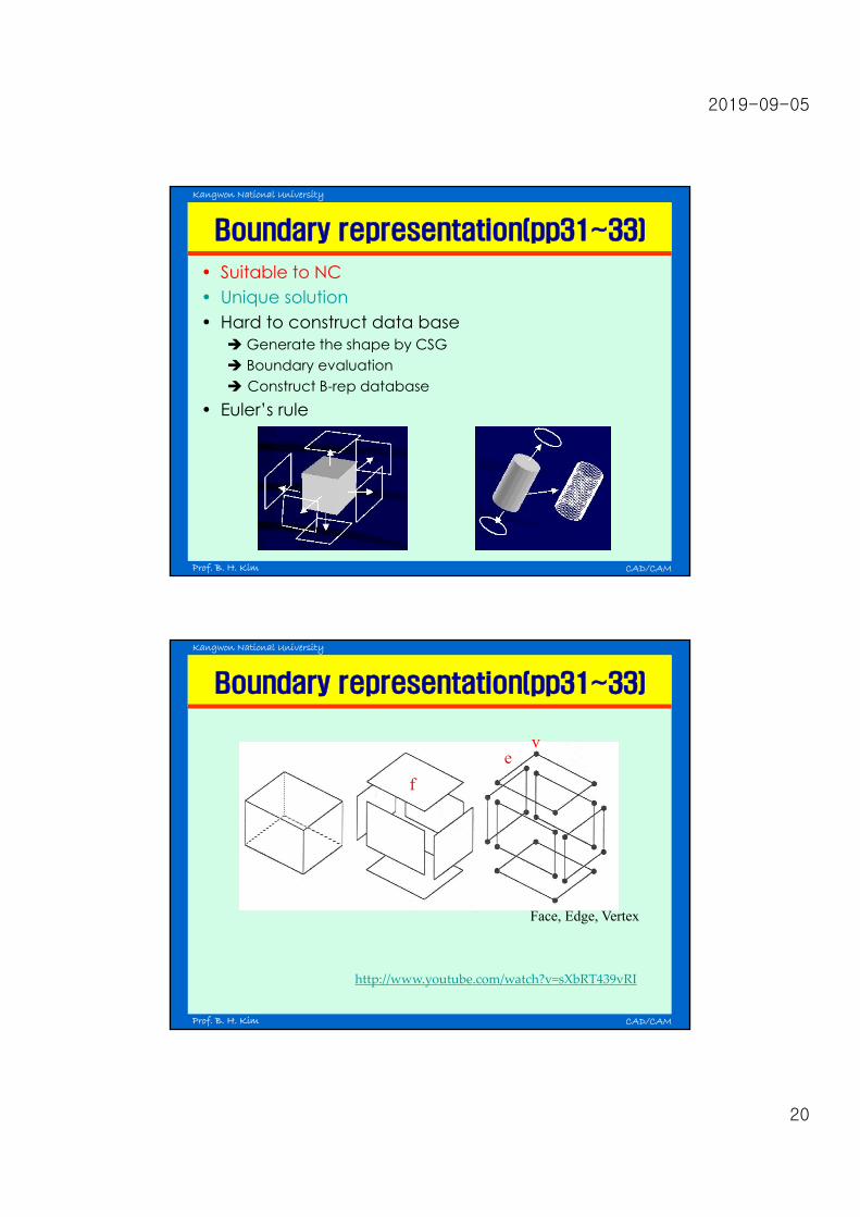
Boundary representation(pp31~33)
Face, Edge, Vertex
ve
f
http://www.youtube.com/watch?v=sXbRT439vRI

2019-09-05
21
Kangwon National University
Prof. B. H. Kim CAD/CAM
B-rep - Euler’s rules (pp31~33)
• No holes : F - E + V = 2 • With holes : F - E + V = 2 + R -2H (extended
Euler rule) R : # of Internal edge rings H : # of through holes
Kangwon National University
Prof. B. H. Kim CAD/CAM
B-rep - data base (pp31~33)

2019-09-05
22
Kangwon National University
Prof. B. H. Kim CAD/CAM
B-rep – Validity (pp31~33)
Elements of the model • should not self-intersect• should not intersect each other unless at their boundary.
Self-intersecting non-manifold (next page)
Kangwon National University
Prof. B. H. Kim CAD/CAM
B-rep - Topologically Equivalent

2019-09-05
23
Kangwon National University
Prof. B. H. Kim CAD/CAM
B-rep - Examples of Non-Manifold Models
Kangwon National University
Prof. B. H. Kim CAD/CAM
CSG vs. B-Rep
CSG B-REP
• Simple representation• Limited to simple
objects• Stored as binary tree• Difficult to calculate• Rarely used anymore
• Flexible and powerfulrepresentation
• Stored explicitly• Can be generated from CSG
representation• Used in current CAD systems

2019-09-05
24
Kangwon National University
Prof. B. H. Kim CAD/CAM
Kangwon National University
Prof. B. H. Kim CAD/CAM
Viewing operation
• Clipping output primitives– Conventional way
. Point: xmin ≤ x ≤ xmax, ymin ≤ y ≤ ymin
. Line: two point in(AB) no clipping,one point in(CD) intersection point cal.two point out(GH, IJ) intersection points cal.
– Cohen-Sutherland clipping algorithm : using bits for simplicity. Top, Bottom, Right side, Left side discard line
window

2019-09-05
25
Kangwon National University
Prof. B. H. Kim CAD/CAM
Curves and Lines - Editing and Creating
• A number of functions must be provided to allow editing of 2Dgeometrical entities, such as lines, circles, arcs.
• Basic editing functions- Basic Entity Creation (lines/ circles/ arcs/ etc)
. create using exact coordinatesEx) two screen points for line ends, circle radius/centre/diameter/etc
- Line Trimming. trim lines back to intersection/extend lines to intersection. trim line to perpendicular point. cut a circle/arc on one side of an intersection
- Point Creation. screen position (exact numerical coordinate). nearest tangent of line to an arc/nearest end of a line. midpoint of nearest line/centre of nearest arc/nearest grid point
- Arc Creation. intersection of circle with another line
- Special Techniques. offset of a line. extend lines to intersection. delete entities
Kangwon National University
Prof. B. H. Kim CAD/CAM
Basic Entity Creation
• Line (P1, P2) :Select icon Move to graphic area Click left mousebutton on start pointMove to end point & clickMove out& double click☞ L = sqrt((xp1-xp2)2+(yp1-yp2)2), = tan-1((yp1-yp2)/(xp1-xp2))
• Curve(P1, P2, P3, …)Select icon Move to graphic area Click left mousebutton on start point Move to 2nd point & click Move to3rd point & double click revise curve by tangent☞ Tangent = r’(=dr/dt), Curvature = |r’ X r”|/|r’|3
tangent
curvature

2019-09-05
26
Kangwon National University
Prof. B. H. Kim CAD/CAM
Basic Entity Creation Ex.1
• Circle (P1, P2 or P3 )Select icon Move to graphic area Click left mousebutton on center pointMove to end point & click☞ R = sqrt((xp1-xp2)2+(yp1-yp2)2), Pc = P1☞ 3 p. circle: Calculating Pc = (x, y), R = sqrt((xp1-x)2+(yp1-y)2)
Kangwon National University
Prof. B. H. Kim CAD/CAM
Basic Entity Creation Ex.2
At SolidWorks Line Trimming
• Step 1 Construction of a basisset of lines to lay out theshape to be drawn.
• Step 2 Pick parts of theconstruction lines to delete

2019-09-05
27
Kangwon National University
Prof. B. H. Kim CAD/CAM
User Interpretation
• Every CAD system uses a graphical display for userinterpretation of the final part.
• The display methods discussed in the computer graphicssection are all used in CAD packages.
• There are many techniques possible with computer graphicsthat make on screen designs easier to understand.
• Dimensioning– Placed manually, but updates when dimensions change.– Annotation : the user may add comments to drawings
text with a leader pointing to something text alone tolerances Drawing information
• Graphics effects– Wireframe model– Solid model– Rendering
Kangwon National University
Prof. B. H. Kim CAD/CAM
Annotation

2019-09-05
28
Kangwon National University
Prof. B. H. Kim CAD/CAM
Graphics effects
Wire model view Solid model view Rendering view