Embed Size (px)
Citation preview

www.new
CHAP T E R 1
Microcomputer Systems
1.1 Introduction
The term microcomputer is used to describe a system that includes at minimum a
microprocessor, program memory, data memory, and an input-output (I/O) device.
Some microcomputer systems include additional components such as timers, counters,
and analog-to-digital converters. Thus, a microcomputer system can be anything from a
large computer having hard disks, floppy disks, and printers to a single-chip embedded
controller.
In this book we are going to consider only the type of microcomputers that consist of
a single silicon chip. Such microcomputer systems are also called microcontrollers, and
they are used in many household goods such as microwave ovens, TV remote control
units, cookers, hi-fi equipment, CD players, personal computers, and refrigerators.
Many different microcontrollers are available on the market. In this book we shall be
looking at programming and system design for the PIC (programmable interface
controller) series of microcontrollers manufactured by Microchip Technology Inc.
1.2 Microcontroller Systems
A microcontroller is a single-chip computer. Micro suggests that the device is
small, and controller suggests that it is used in control applications. Another term for
microcontroller is embedded controller, since most of the microcontrollers are built
into (or embedded in) the devices they control.
A microprocessor differs from a microcontroller in a number of ways. The main
distinction is that a microprocessor requires several other components for its operation,
nespress.com

2 Chapter 1
such as program memory and data memory, input-output devices, and an external clock
circuit. A microcontroller, on the other hand, has all the support chips incorporated
inside its single chip. All microcontrollers operate on a set of instructions (or the user
program) stored in their memory. A microcontroller fetches the instructions from its
program memory one by one, decodes these instructions, and then carries out the
required operations.
Microcontrollers have traditionally been programmed using the assembly language
of the target device. Although the assembly language is fast, it has several
disadvantages. An assembly program consists of mnemonics, which makes learning
and maintaining a program written using the assembly language difficult. Also,
microcontrollers manufactured by different firms have different assembly languages,
so the user must learn a new language with every new microcontroller he or
she uses.
Microcontrollers can also be programmed using a high-level language, such as BASIC,
PASCAL, or C. High-level languages are much easier to learn than assembly languages.
They also facilitate the development of large and complex programs. In this book we
shall be learning the programming of PIC microcontrollers using the popular C
language known as mikroC, developed by mikroElektronika.
In theory, a single chip is sufficient to have a running microcontroller system. In
practical applications, however, additional components may be required so the
microcomputer can interface with its environment. With the advent of the PIC family of
microcontrollers the development time of an electronic project has been reduced to
several hours.
Basically, a microcomputer executes a user program which is loaded in its program
memory. Under the control of this program, data is received from external devices
(inputs), manipulated, and then sent to external devices (outputs). For example, in a
microcontroller-based oven temperature control system the microcomputer reads the
temperature using a temperature sensor and then operates a heater or a fan to keep
the temperature at the required value. Figure 1.1 shows a block diagram of a simple
oven temperature control system.
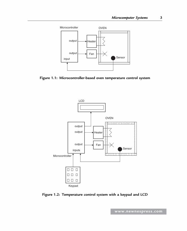
The system shown in Figure 1.1 is very simple. A more sophisticated system may
include a keypad to set the temperature and an LCD to display it. Figure 1.2 shows a
block diagram of this more sophisticated temperature control system.
www.newnespress.com
Heater
FanSensorinput
output
output
OVENMicrocontroller
Figure 1.1: Microcontroller-based oven temperature control system
Heater
FanSensor
inputs
output
output
OVEN
Microcontroller
LCD
output
Keypad
Figure 1.2: Temperature control system with a keypad and LCD
www.newnespress.com
3Microcomputer Systems
4 Chapter 1
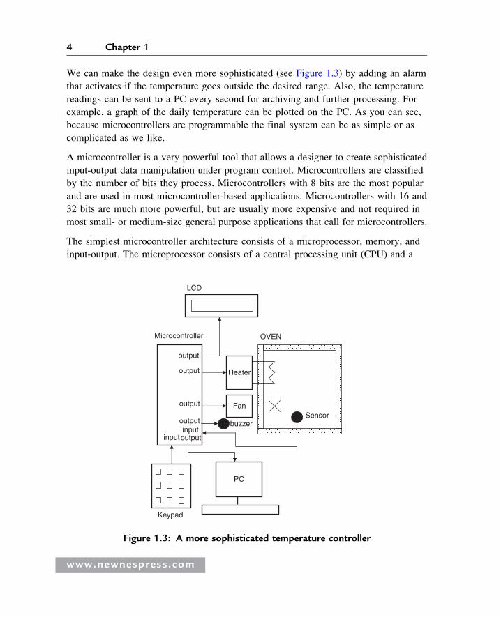
We can make the design even more sophisticated (see Figure 1.3) by adding an alarm
that activates if the temperature goes outside the desired range. Also, the temperature
readings can be sent to a PC every second for archiving and further processing. For
example, a graph of the daily temperature can be plotted on the PC. As you can see,
because microcontrollers are programmable the final system can be as simple or as
complicated as we like.
A microcontroller is a very powerful tool that allows a designer to create sophisticated
input-output data manipulation under program control. Microcontrollers are classified
by the number of bits they process. Microcontrollers with 8 bits are the most popular
and are used in most microcontroller-based applications. Microcontrollers with 16 and
32 bits are much more powerful, but are usually more expensive and not required in
most small- or medium-size general purpose applications that call for microcontrollers.
The simplest microcontroller architecture consists of a microprocessor, memory, and
input-output. The microprocessor consists of a central processing unit (CPU) and a
Heater
FanSensor
input
output
output
OVENMicrocontroller
LCD
output
Keypad
output
PC
buzzeroutput input
Figure 1.3: A more sophisticated temperature controller
www.newnespress.com

5Microcomputer Systems
control unit (CU). The CPU is the brain of the microcontroller; this is where all the
arithmetic and logic operations are performed. The CU controls the internal operations
of the microprocessor and sends signals to other parts of the microcontroller to carry out
the required instructions.
Memory, an important part of a microcontroller system, can be classified into two
types: program memory and data memory. Program memory stores the program written
by the programmer and is usually nonvolatile (i.e., data is not lost after the power is
turned off). Data memory stores the temporary data used in a program and is usually
volatile (i.e., data is lost after the power is turned off).
There are basically six types of memories, summarized as follows:
1.2.1 RAM
RAM, random access memory, is a general purpose memory that usually stores the
user data in a program. RAM memory is volatile in the sense that it cannot retain
data in the absence of power (i.e., data is lost after the power is turned off). Most
microcontrollers have some amount of internal RAM, 256 bytes being a common
amount, although some microcontrollers have more, some less. The PIC18F452
microcontroller, for example, has 1536 bytes of RAM. Memory can usually be extended
by adding external memory chips.
1.2.2 ROM
ROM, read only memory, usually holds program or fixed user data. ROM is
nonvolatile. If power is removed from ROM and then reapplied, the original data
will still be there. ROM memory is programmed during the manufacturing process,
and the user cannot change its contents. ROM memory is only useful if you have
developed a program and wish to create several thousand copies of it.
1.2.3 PROM
PROM, programmable read only memory, is a type of ROM that can be
programmed in the field, often by the end user, using a device called a PROM
programmer. Once a PROM has been programmed, its contents cannot be changed.
PROMs are usually used in low production applications where only a few such
memories are required.
www.newnespress.com

6 Chapter 1
1.2.4 EPROM
EPROM, erasable programmable read only memory, is similar to ROM, but EPROM
can be programmed using a suitable programming device. An EPROM memory has a
small clear-glass window on top of the chip where the data can be erased under strong
ultraviolet light. Once the memory is programmed, the window can be covered with
dark tape to prevent accidental erasure of the data. An EPROM memory must be erased
before it can be reprogrammed. Many developmental versions of microcontrollers are
manufactured with EPROM memories where the user program can be stored. These
memories are erased and reprogrammed until the user is satisfied with the program.
Some versions of EPROMs, known as OTP (one time programmable), can be
programmed using a suitable programmer device but cannot be erased. OTP memories
cost much less than EPROMs. OTP is useful after a project has been developed
completely and many copies of the program memory must be made.
1.2.5 EEPROM
EEPROM, electrically erasable programmable read only memory, is a nonvolatile
memory that can be erased and reprogrammed using a suitable programming device.
EEPROMs are used to save configuration information, maximum and minimum values,
identification data, etc. Some microcontrollers have built-in EEPROM memories. For
instance, the PIC18F452 contains a 256-byte EEPROM memory where each byte can be
programmed and erased directly by applications software. EEPROM memories are
usually very slow. An EEPROM chip is much costlier than an EPROM chip.
1.2.6 Flash EEPROM
Flash EEPROM, a version of EEPROM memory, has become popular in microcontroller
applications and is used to store the user program. Flash EEPROM is nonvolatile and
usually very fast. The data can be erased and then reprogrammed using a suitable
programming device. Some microcontrollers have only 1K flash EEPROM while others
have 32K or more. The PIC18F452 microcontroller has 32K bytes of flash memory.
1.3 Microcontroller Features
Microcontrollers from different manufacturers have different architectures and different
capabilities. Some may suit a particular application while others may be totally
www.newnespress.com

7Microcomputer Systems
unsuitable for the same application. The hardware features common to most
microcontrollers are described in this section.
1.3.1 Supply Voltage
Most microcontrollers operate with the standard logic voltage of þ5V. Some
microcontrollers can operate at as low as þ2.7V, and some will tolerate þ6V without
any problem. The manufacturer’s data sheet will have information about the allowed
limits of the power supply voltage. PIC18F452 microcontrollers can operate with a
power supply of þ2V to þ5.5V.
Usually, a voltage regulator circuit is used to obtain the required power supply voltage
when the device is operated from a mains adapter or batteries. For example, a 5V
regulator is required if the microcontroller is operated from a 5V supply using a 9V
battery.
1.3.2 The Clock
All microcontrollers require a clock (or an oscillator) to operate, usually provided by
external timing devices connected to the microcontroller. In most cases, these external
timing devices are a crystal plus two small capacitors. In some cases they are resonators
or an external resistor-capacitor pair. Some microcontrollers have built-in timing
circuits and do not require external timing components. If an application is not time-
sensitive, external or internal (if available) resistor-capacitor timing components are the
best option for their simplicity and low cost.
An instruction is executed by fetching it from the memory and then decoding it. This
usually takes several clock cycles and is known as the instruction cycle. In PIC
microcontrollers, an instruction cycle takes four clock periods. Thus the microcontroller
operates at a clock rate that is one-quarter of the actual oscillator frequency. The
PIC18F series of microcontrollers can operate with clock frequencies up to 40MHz.
1.3.3 Timers
Timers are important parts of any microcontroller. A timer is basically a counter which
is driven from either an external clock pulse or the microcontroller’s internal oscillator.
A timer can be 8 bits or 16 bits wide. Data can be loaded into a timer under program
control, and the timer can be stopped or started by program control. Most timers can be
www.newnespress.com

8 Chapter 1
configured to generate an interrupt when they reach a certain count (usually when they
overflow). The user program can use an interrupt to carry out accurate timing-related
operations inside the microcontroller. Microcontrollers in the PIC18F series have at
least three timers. For example, the PIC18F452 microcontroller has three built-in
timers.
Some microcontrollers offer capture and compare facilities, where a timer value can be
read when an external event occurs, or the timer value can be compared to a preset
value, and an interrupt is generated when this value is reached. Most PIC18F
microcontrollers have at least two capture and compare modules.
1.3.4 Watchdog
Most microcontrollers have at least one watchdog facility. The watchdog is basically a
timer that is refreshed by the user program. Whenever the program fails to refresh
the watchdog, a reset occurs. The watchdog timer is used to detect a system problem,
such as the program being in an endless loop. This safety feature prevents runaway
software and stops the microcontroller from executing meaningless and unwanted
code. Watchdog facilities are commonly used in real-time systems where the
successful termination of one or more activities must be checked regularly.
1.3.5 Reset Input
A reset input is used to reset a microcontroller externally. Resetting puts the
microcontroller into a known state such that the program execution starts from address
0 of the program memory. An external reset action is usually achieved by connecting
a push-button switch to the reset input. When the switch is pressed, the microcontroller
is reset.
1.3.6 Interrupts
Interrupts are an important concept in microcontrollers. An interrupt causes the
microcontroller to respond to external and internal (e.g., a timer) events very quickly.
When an interrupt occurs, the microcontroller leaves its normal flow of program
execution and jumps to a special part of the program known as the interrupt service
routine (ISR). The program code inside the ISR is executed, and upon return from the
ISR the program resumes its normal flow of execution.
www.newnespress.com

9Microcomputer Systems
The ISR starts from a fixed address of the program memory sometimes known as the
interrupt vector address. Some microcontrollers with multi-interrupt features have just
one interrupt vector address, while others have unique interrupt vector addresses, one
for each interrupt source. Interrupts can be nested such that a new interrupt can suspend
the execution of another interrupt. Another important feature of multi-interrupt
capability is that different interrupt sources can be assigned different levels of priority.
For example, the PIC18F series of microcontrollers has both low-priority and high-
priority interrupt levels.
1.3.7 Brown-out Detector
Brown-out detectors, which are common in many microcontrollers, reset the
microcontroller if the supply voltage falls below a nominal value. These safety features
can be employed to prevent unpredictable operation at low voltages, especially to
protect the contents of EEPROM-type memories.
1.3.8 Analog-to-Digital Converter
An analog-to-digital converter (A/D) is used to convert an analog signal, such as
voltage, to digital form so a microcontroller can read and process it. Some
microcontrollers have built-in A/D converters. External A/D converter can also be
connected to any type of microcontroller. A/D converters are usually 8 to 10 bits,
having 256 to 1024 quantization levels. Most PIC microcontrollers with A/D features
have multiplexed A/D converters which provide more than one analog input channel.
For example, the PIC18F452 microcontroller has 10-bit 8-channel A/D converters.
The A/D conversion process must be started by the user program and may take several
hundred microseconds to complete. A/D converters usually generate interrupts when a
conversion is complete so the user program can read the converted data quickly.
A/D converters are especially useful in control and monitoring applications, since most
sensors (e.g., temperature sensors, pressure sensors, force sensors, etc.) produce analog
output voltages.
1.3.9 Serial Input-Output
Serial communication (also called RS232 communication) enables a microcontroller
to be connected to another microcontroller or to a PC using a serial cable. Some
www.newnespress.com
10 Chapter 1
microcontrollers have built-in hardware called USART (universal synchronous-
asynchronous receiver-transmitter) to implement a serial communication interface.
The user program can usually select the baud rate and data format. If no serial
input-output hardware is provided, it is easy to develop software to implement serial
data communication using any I/O pin of a microcontroller. The PIC18F series of
microcontrollers has built-in USART modules. We shall see in Chapter 6 how to write
mikroC programs to implement serial communicationwith andwithout aUSARTmodule.
Some microcontrollers (e.g., the PIC18F series) incorporate SPI (serial peripheral
interface) or I2C (integrated interconnect) hardware bus interfaces. These enable a
microcontroller to interface with other compatible devices easily.
1.3.10 EEPROM Data Memory
EEPROM-type data memory is also very common in many microcontrollers. The
advantage of an EEPROM memory is that the programmer can store nonvolatile data
there and change this data whenever required. For example, in a temperature monitoring
application, the maximum and minimum temperature readings can be stored in an
EEPROMmemory. If the power supply is removed for any reason, the values of the latest
readings are available in the EEPROMmemory. The PIC18F452 microcontroller has 256
bytes of EEPROM memory. Other members of the PIC18F family have more EEPROM
memory (e.g., the PIC18F6680 has 1024 bytes). The mikroC language provides special
instructions for reading and writing to the EEPROM memory of a PIC microcontroller.
1.3.11 LCD Drivers
LCD drivers enable a microcontroller to be connected to an external LCD display
directly. These drivers are not common since most of the functions they provide can be
implemented in software. For example, the PIC18F6490 microcontroller has a built-in
LCD driver module.
1.3.12 Analog Comparator
Analog comparators are used where two analog voltages need to be compared.
Although these circuits are implemented in most high-end PIC microcontrollers, they
are not common in other microcontrollers. The PIC18F series of microcontrollers has
built-in analog comparator modules.
www.newnespress.com

11Microcomputer Systems
1.3.13 Real-time Clock
A real-time clock enables a microcontroller to receive absolute date and time
information continuously. Built-in real-time clocks are not common in most
microcontrollers, since the same function can easily be implemented by either a
dedicated real-time clock chip or a program written for this purpose.
1.3.14 Sleep Mode
Some microcontrollers (e.g., PICs) offer built-in sleep modes, where executing this
instruction stops the internal oscillator and reduces power consumption to an extremely
low level. The sleep mode’s main purpose is to conserve battery power when the
microcontroller is not doing anything useful. The microcontroller is usually woken up
from sleep mode by an external reset or a watchdog time-out.
1.3.15 Power-on Reset
Some microcontrollers (e.g., PICs) have built-in power-on reset circuits which keep the
microcontroller in the reset state until all the internal circuitry has been initialized. This
feature is very useful, as it starts the microcontroller from a known state on power-up.
An external reset can also be provided, where the microcontroller is reset when an
external button is pressed.
1.3.16 Low-Power Operation
Low-power operation is especially important in portable applications where
microcontroller-based equipment is operated from batteries. Some microcontrollers
(e.g., PICs) can operate with less than 2mA with a 5V supply, and around 15mA at a 3V
supply. Other microcontrollers, especially microprocessor-based systems with several
chips, may consume several hundred milliamperes or even more.
1.3.17 Current Sink/Source Capability
Current sink/source capability is important if the microcontroller is to be connected
to an external device that might draw a large amount of current to operate. PIC
microcontrollers can source and sink 25mA of current from each output port pin. This
current is usually sufficient to drive LEDs, small lamps, buzzers, small relays, etc. The
www.newnespress.com

12 Chapter 1
current capability can be increased by connecting external transistor switching circuits
or relays to the output port pins.
1.3.18 USB Interface
USB is currently a very popular computer interface specification used to connect
various peripheral devices to computers and microcontrollers. Some PIC
microcontrollers provide built-in USB modules. The PIC18F2x50, for example,
has built-in USB interface capabilities.
1.3.19 Motor Control Interface
Some PIC microcontrollers, for example the PIC18F2x31, provide motor control
interface capability.
1.3.20 CAN Interface
CAN bus is a very popular bus system used mainly in automation applications. Some
PIC18F-series microcontrollers (e.g., the PIC18F4680) provide CAN interface
capability.
1.3.21 Ethernet Interface
Some PIC microcontrollers (e.g., the PIC18F97J60) provide Ethernet interface
capabilities and thus are easily used in network-based applications.
1.3.22 ZigBee Interface
ZigBee, an interface similar to Bluetooth, is used in low-cost wireless home automation
applications. Some PIC18F-series microcontrollers provide ZigBee interface
capabilities, making the design of such wireless systems very easy.
1.4 Microcontroller Architectures
Two types of architectures are conventional in microcontrollers (see Figure 1.4).
Von Neumann architecture, used by a large percentage of microcontrollers, places
all memory space on the same bus; instruction and data also use the same bus.
www.newnespress.com

CPU Datamemory
Programmemory
CPU Programmemory
Von Neumann architecture Harvard architecture a) b)
Figure 1.4: Von Neumann and Harvard architectures
13Microcomputer Systems
In Harvard architecture (used by PIC microcontrollers), code and data are on
separate buses, which allows them to be fetched simultaneously, resulting in an
improved performance.
1.4.1 RISC and CISC
RISC (reduced instruction set computer) and CISC (complex instruction computer)
refer to the instruction set of a microcontroller. In an 8-bit RISC microcontroller,
data is 8 bits wide but the instruction words are more than 8 bits wide (usually
12, 14, or 16 bits) and the instructions occupy one word in the program memory.
Thus the instructions are fetched and executed in one cycle, which improves
performance.
In a CISC microcontroller, both data and instructions are 8 bits wide. CISC
microcontrollers usually have over two hundred instructions. Data and code are on the
same bus and cannot be fetched simultaneously.
1.5 Number Systems
To use a microprocessor or microcontroller efficiently requires a working knowledge
of binary, decimal, and hexadecimal numbering systems. This section provides
background information about these numbering systems for readers who are unfamiliar
with them or do not know how to convert from one number system to another.
Number systems are classified according to their bases. The numbering system used in
everyday life is base 10, or the decimal number system. The numbering system most
www.newnespress.com

14 Chapter 1
commonly used in microprocessor and microcontroller applications is base 16,
or hexadecimal. Base 2, or binary, and base 8, or octal, number systems are
also used.
1.5.1 Decimal Number System
The numbers in the decimal number system, of course, are 0, 1, 2, 3, 4, 5, 6, 7, 8, 9. The
subscript 10 indicates that a number is in decimal format. For example, the decimal
number 235 is shown as 23510.
In general, a decimal number is represented as follows:
an � 10n þ an�1 � 10n�1 þ an�2 � 10n�2 þ ::::::::: þ a0 � 100
For example, decimal number 82510 can be shown as:
82510 ¼ 8 � 102 þ 2 � 101 þ 5 � 100
Similarly, decimal number 2610 can be shown as:
2610 ¼ 2 � 101 þ 6 � 100
or
335910 ¼ 3 � 103 þ 3 � 102 þ 5 � 101 þ 9 � 100
1.5.2 Binary Number System
The binary number system consists of two numbers: 0 and 1. A subscript 2 indicates that a
number is in binary format. For example, the binary number 1011 would be 10112.
In general, a binary number is represented as follows:
an � 2n þ an�1 � 2n�1 þ an�2 � 2n�2 þ ::::::::: þ a0 � 20
For example, binary number 11102 can be shown as:
11102 ¼ 1 � 23 þ 1 � 22 þ 1 � 21 þ 0 � 20
www.newnespress.com

15Microcomputer Systems
Similarly, binary number 100011102 can be shown as:
100011102 ¼ 1 � 27 þ 0 � 26 þ 0 � 25 þ 0 � 24 þ 1 � 23
þ 1 � 22 þ 1 � 21 þ 0 � 20
1.5.3 Octal Number System
In the octal number system, the valid numbers are 0, 1, 2, 3, 4, 5, 6, 7. A subscript
8 indicates that a number is in octal format. For example, the octal number 23 appears
as 238.
In general, an octal number is represented as:
an � 8n þ an�1 � 8n�1 þ an�2 � 8n�2 þ ::::::::: þ a0 � 80
For example, octal number 2378 can be shown as:
2378 ¼ 2 � 82 þ 3 � 81 þ 7 � 80
Similarly, octal number 17778 can be shown as:
17778 ¼ 1 � 83 þ 7 � 82 þ 7 � 81 þ 7 � 80
1.5.4 Hexadecimal Number System
In the hexadecimal number system, the valid numbers are: 0, 1, 2, 3, 4, 5, 6, 7, 8, 9, A,
B, C, D, E, F. A subscript 16 or subscript H indicates that a number is in hexadecimal
format. For example, hexadecimal number 1F can be written as 1F16 or as 1FH.
In general, a hexadecimal number is represented as:
an � 16n þ an�1 � 16n�1 þ an�2 � 16n�2 þ ::::::::: þ a0 � 160
For example, hexadecimal number 2AC16 can be shown as:
2AC16 ¼ 2 � 162 þ 10 � 161 þ 12 � 160
Similarly, hexadecimal number 3FFE16 can be shown as:
3FFE16 ¼ 3 � 163 þ 15 � 162 þ 15 � 161 þ 14 � 160
www.newnespress.com
16 Chapter 1
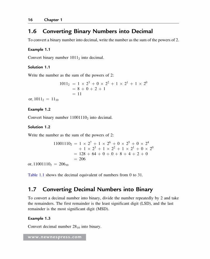
1.6 Converting Binary Numbers into Decimal
To convert a binary number into decimal, write the number as the sum of the powers of 2.
Example 1.1
Convert binary number 10112 into decimal.
Solution 1.1
Write the number as the sum of the powers of 2:
10112 ¼ 1 � 23 þ 0 � 22 þ 1 � 21 þ 1 � 20
¼ 8 þ 0 þ 2 þ 1
¼ 11
or; 10112 ¼ 1110
Example 1.2
Convert binary number 110011102 into decimal.
Solution 1.2
Write the number as the sum of the powers of 2:
110011102 ¼ 1 � 27 þ 1 � 26 þ 0 � 25 þ 0 � 24
þ 1 � 23 þ 1 � 22 þ 1 � 21 þ 0 � 20
¼ 128 þ 64 þ 0 þ 0 þ 8 þ 4 þ 2 þ 0
¼ 206
or; 110011102 ¼ 20610
Table 1.1 shows the decimal equivalent of numbers from 0 to 31.
1.7 Converting Decimal Numbers into Binary
To convert a decimal number into binary, divide the number repeatedly by 2 and take
the remainders. The first remainder is the least significant digit (LSD), and the last
remainder is the most significant digit (MSD).
Example 1.3
Convert decimal number 2810 into binary.
www.newnespress.com

Table 1.1: Decimal equivalent ofbinary numbers
Binary Decimal Binary Decimal
00000000 0 00010000 16
00000001 1 00010001 17
00000010 2 00010010 18
00000011 3 00010011 19
00000100 4 00010100 20
00000101 5 00010101 21
00000110 6 00010110 22
00000111 7 00010111 23
00001000 8 00011000 24
00001001 9 00011001 25
00001010 10 00011010 26
00001011 11 00011011 27
00001100 12 00011100 28
00001101 13 00011101 29
00001110 14 00011110 30
00001111 15 00011111 31
17Microcomputer Systems
Solution 1.3
Divide the number into 2 repeatedly and take the remainders:
28/2 ! 14 Remainder 0 (LSD)14/2 ! 7 Remainder 07/2 ! 3 Remainder 13/2 ! 1 Remainder 11/2 ! 0 Remeinder 1 (MSD)
The binary number is 111002.
www.newnespress.com

18 Chapter 1
Example 1.4
Convert decimal number 6510 into binary.
Solution 1.4
Divide the number into 2 repeatedly and take the remainders:
65/2 ! 32 Remainder 1 (LSD)32/2 ! 16 Remainder 016/2 ! 8 Remainder 08/2 ! 4 Remainder 04/2 ! 2 Remainder 02/2 ! 1 Remainder 01/2 ! 0 Remainder 1 (MSD)
The binary number is 10000012.
Example 1.5
Convert decimal number 12210 into binary.
Solution 1.5
Divide the number into 2 repeatedly and take the remainders:
122/2 ! 61 Remainder 0 (LSD)61/2 ! 30 Remainder 130/2 ! 15 Remainder 015/2 ! 7 Remainder 17/2 ! 3 Remainder 13/2 ! 1 Remainder 11/2 ! 0 Remainder 1 (MSD)
The binary number is 11110102.
1.8 Converting Binary Numbers into Hexadecimal
To convert a binary number into hexadecimal, arrange the number in groups of four and
find the hexadecimal equivalent of each group. If the number cannot be divided exactly
into groups of four, insert zeros to the left of the number as needed so the number of
digits are divisible by four.
www.newnespress.com

19Microcomputer Systems
Example 1.6
Convert binary number 100111112 into hexadecimal.
Solution 1.6
First, divide the number into groups of four, then find the hexadecimal equivalent of
each group:
10011111 = 1001 11119 F
The hexadecimal number is 9F16.
Example 1.7
Convert binary number 11101111000011102 into hexadecimal.
Solution 1.7
First, divide the number into groups of four, then find the hexadecimal equivalent of
each group:
1110111100001110 = 1110 1111 0000 1110E F 0 E
The hexadecimal number is EF0E16.
Example 1.8
Convert binary number 1111102 into hexadecimal.
Solution 1.8
Since the number cannot be divided exactly into groups of four, we have to insert, in
this case, two zeros to the left of the number so the number of digits is divisible by four:
111110 = 0011 11103 E
The hexadecimal number is 3E16.
Table 1.2 shows the hexadecimal equivalent of numbers 0 to 31.
www.newnespress.com

Table 1.2: Hexadecimal equivalent ofdecimal numbers
Decimal Hexadecimal Decimal Hexadecimal
0 0 16 10
1 1 17 11
2 2 18 12
3 3 19 13
4 4 20 14
5 5 21 15
6 6 22 16
7 7 23 17
8 8 24 18
9 9 25 19
10 A 26 1A
11 B 27 1B
12 C 28 1C
13 D 29 1D
14 E 30 1E
15 F 31 1F
20 Chapter 1
1.9 Converting Hexadecimal Numbers into Binary
To convert a hexadecimal number into binary, write the 4-bit binary equivalent of each
hexadecimal digit.
Example 1.9
Convert hexadecimal number A916 into binary.
www.newnespress.com

21Microcomputer Systems
Solution 1.9
Writing the binary equivalent of each hexadecimal digit:
A = 10102 9 = 10012
The binary number is 101010012.
Example 1.10
Convert hexadecimal number FE3C16 into binary.
Solution 1.10
Writing the binary equivalent of each hexadecimal digit:
F = 11112 E = 11102 3 = 00112 C = 11002
The binary number is 11111110001111002.
1.10 Converting Hexadecimal Numbers into Decimal
To convert a hexadecimal number into decimal, calculate the sum of the powers of
16 of the number.
Example 1.11
Convert hexadecimal number 2AC16 into decimal.
Solution 1.11
Calculating the sum of the powers of 16 of the number:
2AC16 ¼ 2 � 162 þ 10 � 161 þ 12 � 160
¼ 512 þ 160 þ 12
¼ 684
The required decimal number is 68410.
Example 1.12
Convert hexadecimal number EE16 into decimal.
www.newnespress.com

22 Chapter 1
Solution 1.12
Calculating the sum of the powers of 16 of the number:
EE16 ¼ 14 � 161 þ 14 � 160
¼ 224 þ 14
¼ 238
The decimal number is 23810.
1.11 Converting Decimal Numbers into Hexadecimal
To convert a decimal number into hexadecimal, divide the number repeatedly by 16 and
take the remainders. The first remainder is the LSD, and the last remainder is the MSD.
Example 1.13
Convert decimal number 23810 into hexadecimal.
Solution 1.13
Dividing the number repeatedly by 16:
238/16 ! 14 Remainder 14 (E) (LSD)14/16 ! 0 Remainder 14 (E) (MSD)
The hexadecimal number is EE16.
Example 1.14
Convert decimal number 68410 into hexadecimal.
Solution 1.14
Dividing the number repeatedly by 16:
684/16 ! 42 Remainder 12 (C) (LSD)42/16 ! 2 Remainder 10 (A)2/16 ! 0 Remainder 2 (MSD)
The hexadecimal number is 2AC16.
www.newnespress.com

23Microcomputer Systems
1.12 Converting Octal Numbers into Decimal
To convert an octal number into decimal, calculate the sum of the powers of 8 of the
number.
Example 1.15
Convert octal number 158 into decimal.
Solution 1.15
Calculating the sum of the powers of 8 of the number:
158 ¼ 1 � 81 þ 5 � 80
¼ 8 þ 5
¼ 13
The decimal number is 1310.
Example 1.16
Convert octal number 2378 into decimal.
Solution 1.16
Calculating the sum of the powers of 8 of the number:
2378 ¼ 2 � 82 þ 3 � 81 þ 7 � 80
¼ 128 þ 24 þ 7
¼ 159
The decimal number is 15910.
1.13 Converting Decimal Numbers into Octal
To convert a decimal number into octal, divide the number repeatedly by 8 and take the
remainders. The first remainder is the LSD, and the last remainder is
the MSD.
Example 1.17
Convert decimal number 15910 into octal.
www.newnespress.com

24 Chapter 1
Solution 1.17
Dividing the number repeatedly by 8:
159/8 ! 19 Remainder 7 (LSD)19/8 ! 2 Remainder 32/8 ! 0 Remainder 2 (MSD)
The octal number is 2378.
Example 1.18
Convert decimal number 46010 into octal.
Solution 1.18
Dividing the number repeatedly by 8:
460/8 ! 57 Remainder 4 (LSD)57/8 ! 7 Remainder 17/8 ! 0 Remainder 7 (MSD)
The octal number is 7148.
Table 1.3 shows the octal equivalent of decimal numbers 0 to 31.
1.14 Converting Octal Numbers into Binary
To convert an octal number into binary, write the 3-bit binary equivalent of each
octal digit.
Example 1.19
Convert octal number 1778 into binary.
Solution 1.19
Write the binary equivalent of each octal digit:
1 = 0012 7 = 1112 7 = 1112
The binary number is 0011111112.
www.newnespress.com
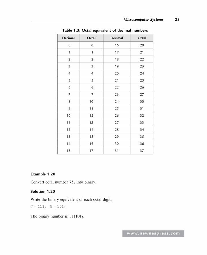
Table 1.3: Octal equivalent of decimal numbers
Decimal Octal Decimal Octal
0 0 16 20
1 1 17 21
2 2 18 22
3 3 19 23
4 4 20 24
5 5 21 25
6 6 22 26
7 7 23 27
8 10 24 30
9 11 25 31
10 12 26 32
11 13 27 33
12 14 28 34
13 15 29 35
14 16 30 36
15 17 31 37
25Microcomputer Systems
Example 1.20
Convert octal number 758 into binary.
Solution 1.20
Write the binary equivalent of each octal digit:
7 = 1112 5 = 1012
The binary number is 1111012.
www.newnespress.com
26 Chapter 1
1.15 Converting Binary Numbers into Octal
To convert a binary number into octal, arrange the number in groups of three and write
the octal equivalent of each digit.
Example 1.21
Convert binary number 1101110012 into octal.
Solution 1.21
Arranging in groups of three:
110111001 = 110 111 0016 7 1
The octal number is 6718.
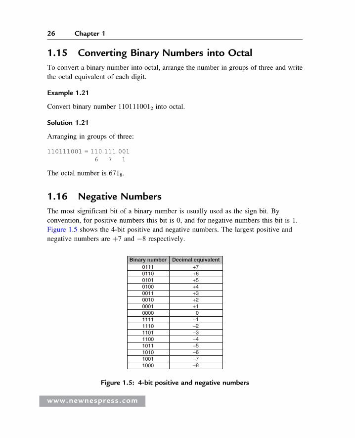
1.16 Negative Numbers
The most significant bit of a binary number is usually used as the sign bit. By
convention, for positive numbers this bit is 0, and for negative numbers this bit is 1.
Figure 1.5 shows the 4-bit positive and negative numbers. The largest positive and
negative numbers are þ7 and �8 respectively.
+5+4+3+2+1
0−1−2−3−4−5−6 −7−8
0111 +70110 +601010100001100100001000011111110110111001011101010011000
Decimal equivalent Binary number
Figure 1.5: 4-bit positive and negative numbers
www.newnespress.com

27Microcomputer Systems
To convert a positive number to negative, take the complement of the number
and add 1. This process is also called the 2’s complement of the
number.
Example 1.22
Write decimal number �6 as a 4-bit number.
Solution 1.22
First, write the number as a positive number, then find the complement and
add 1:
0110 þ6
1001 complement
1 add 1––––
1010 which is �6
Example 1.23
Write decimal number �25 as a 8-bit number.
Solution 1.23
First, write the number as a positive number, then find the complement and
add 1:
00011001 þ25
11100110 complement
1 add 1–––––––
11100111 which is �25
1.17 Adding Binary Numbers
The addition of binary numbers is similar to the addition of decimal numbers. Numbers
in each column are added together with a possible carry from a previous column. The
primitive addition operations are:
www.newnespress.com

28 Chapter 1
0 þ 0 = 00 þ 1 = 11 þ 0 = 11 þ 1 = 10 generate a carry bit1 þ 1 þ 1 = 11 generate a carry bit
Some examples follow.
Example 1.24
Find the sum of binary numbers 011 and 110.
Solution 1.24
We can add these numbers as in the addition of decimal numbers:
011 First column: 1 þ 0 ¼ 1
þ 110 Second column: 1 þ 1 ¼ 0 and a carry bit––––– Third column: 1 þ 1 ¼ 10
1001
Example 1.25
Find the sum of binary numbers 01000011 and 00100010.
Solution 1.25
We can add these numbers as in the addition of decimal numbers:
01000011 First column: 1 þ 0 ¼ 1
þ 00100010 Second column: 1 þ 1 ¼ 10–––––––––- Third column: 0 þ carry ¼ 1
01100101 Fourth column: 0 þ 0 ¼ 0
Fifth column: 0 þ 0 ¼ 0
Sixth column: 0 þ 1 ¼ 1
Seventh column: 1 þ 0 ¼ 1
Eighth column: 0 þ 0 ¼ 0
www.newnespress.com

29Microcomputer Systems
1.18 Subtracting Binary Numbers
To subtract one binary number from another, convert the number to be subtracted into
negative and then add the two numbers.
Example 1.26
Subtract binary number 0010 from 0110.
Solution 1.26
First, convert the number to be subtracted into negative:
0010 number to be subtracted
1101 complement
1 add 1––––
1110
Now add the two numbers:
0110þ 1110––––––
0100
Since we are using only 4 bits, we cannot show the carry bit.
1.19 Multiplication of Binary Numbers
Multiplication of two binary numbers is similar to the multiplication of two decimal
numbers. The four possibilities are:
0 � 0 ¼ 0
0 � 1 ¼ 0
1 � 0 ¼ 0
1 � 1 ¼ 1
Some examples follow.
www.newnespress.com

30 Chapter 1
Example 1.27
Multiply the two binary numbers 0110 and 0010.
Solution 1.27
Multiplying the numbers:
0110
0010-- -- -- --
0000
0110
0000
0000-- -- -- -- -- --
001100 or 1100
In this example 4 bits are needed to show the final result.
Example 1.28
Multiply binary numbers 1001 and 1010.
Solution 1.28
Multiplying the numbers:
1001
1010-- -- -- --0000
1001
0000
1001-- -- -- -- -- --
1011010
In this example 7 bits are required to show the final result.
www.newnespress.com

31Microcomputer Systems
1.20 Division of Binary Numbers
Division with binary numbers is similar to division with decimal numbers. An example
follows.
Example 1.29
Divide binary number 1110 into binary number 10.
Solution 1.29
Dividing the numbers:
111
10 j―――111010-- -- -- --
11
10-- -- -- --
10
10-- -- -- --
00
gives the result 1112.
1.21 Floating Point Numbers
Floating point numbers are used to represent noninteger fractional numbers, for
example, 3.256, 2.1, 0.0036, and so forth. Floating point numbers are used in most
engineering and technical calculations. The most common floating point standard is the
IEEE standard, according to which floating point numbers are represented with 32 bits
(single precision) or 64 bits (double precision).
In this section we are looking at the format of 32-bit floating point numbers only and
seeing how mathematical operations can be performed with such numbers.
www.newnespress.com

32 Chapter 1
According to the IEEE standard, 32-bit floating point numbers are represented as:
31 30 23 22 0
X XXXXXXXX XXXXXXXXXXXXXXXXXXXXXXX
" " "sign exponent mantissa
The most significant bit indicates the sign of the number, where 0 indicates the number
is positive, and 1 indicates it is negative.
The 8-bit exponent shows the power of the number. To make the calculations easy,
the sign of the exponent is not shown; instead, the excess-128 numbering system
is used. Thus, to find the real exponent we have to subtract 127 from the given
exponent. For example, if the mantissa is “10000000,” the real value of the mantissa
is 128 – 127 ¼ 1.
The mantissa is 23 bits wide and represents the increasing negative powers of 2. For
example, if we assume that the mantissa is “1110000000000000000000,” the value of
this mantissa is calculated as 2�1 þ 2�2 þ 2�3 ¼ 7/8.
The decimal equivalent of a floating point number can be calculated using the
formula:
Number ¼ �1ð Þs 2e�127 1:f
where
s ¼ 0 for positive numbers, 1 for negative numbers
w
e ¼ exponent (between 0 and 255)
f ¼ mantissa
As shown in this formula, there is a hidden 1 in front of the mantissa (i.e, the mantissa is
shown as 1.f ).
The largest number in 32-bit floating point format is:
0 11111110 11111111111111111111111
This number is (2 – 2�23) 2127 or decimal 3.403 � 1038. The numbers keep their
precision up to 6 digits after the decimal point.
ww.newnespress.com
33Microcomputer Systems
The smallest number in 32-bit floating point format is:
0 00000001 00000000000000000000000
This number is 2�126 or decimal 1.175 � 10�38.
1.22 Converting a Floating Point Number into Decimal
To convert a given floating point number into decimal, we have to find the mantissa and
the exponent of the number and then convert into decimal as just shown.
Some examples are given here.
Example 1.30
Find the decimal equivalent of the floating point number: 0 10000001
10000000000000000000000
Solution 1.30
Here
sign = positiveexponent = 129 – 127 = 2mantissa = 2-1 = 0.5
The decimal equivalent of this number is þ1.5 � 22 ¼ þ6.0.
Example 1.31
Find the decimal equivalent of the floating point number: 0 10000010
11000000000000000000
Solution 1.31
In this example,
sign = positiveexponent = 130 – 127 = 3mantissa = 2-1 þ 2-2 = 0.75
The decimal equivalent of the number is þ1.75 � 23 ¼ 14.0.
www.newnespress.com

34 Chapter 1
1.22.1 Normalizing Floating Point Numbers
Floating point numbers are usually shown in normalized form. A normalized number
has only one digit before the decimal point (a hidden number 1 is assumed before the
decimal point).
To normalize a given floating point number, we have to move the decimal point
repeatedly one digit to the left and increase the exponent after each move.
Some examples follow.
Example 1.32
Normalize the floating point number 123.56
Solution 1.32
If we write the number with a single digit before the decimal point we get:
1.2356 x 10²
Example 1.33
Normalize the binary number 1011.12
Solution 1.33
If we write the number with a single digit before the decimal point we get:
1.0111 x 23
1.22.2 Converting a Decimal Number into Floating Point
To convert a given decimal number into floating point, carry out the following steps:
� Write the number in binary.
� Normalize the number.
� Find the mantissa and the exponent.
� Write the number as a floating point number.
Some examples follow:
www.newnespress.com

35Microcomputer Systems
Example 1.34
Convert decimal number 2.2510 into floating point.
Solution 1.34
Write the number in binary:
2:2510 ¼ 10:012
Normalize the number:
10:012 ¼ 1:0012 � 21
Here, s ¼ 0, e – 127 ¼ 1 or e ¼ 128, and f ¼ 00100000000000000000000.
(Remember that a number 1 is assumed on the left side, even though it is not shown in
the calculation). The required floating point number can be written as:
s e f0 10000000 (1)001 0000 0000 0000 0000 0000
or, the required 32-bit floating point number is:
01000000000100000000000000000000
Example 1.35
Convert the decimal number 134.062510 into floating point.
Solution 1.35
Write the number in binary:
134.062510 = 10000110.0001
Normalize the number:
10000110.0001 = 1.00001100001 x 27
Here, s ¼ 0, e – 127 ¼ 7 or e ¼ 134, and f ¼ 00001100001000000000000.
www.newnespress.com

36 Chapter 1
The required floating point number can be written as:
s e f0 10000110 (1)00001100001000000000000
or, the required 32-bit floating point number is:
01000011000001100001000000000000
1.22.3 Multiplication and Division of Floating Point Numbers
Multiplication and division of floating point numbers are rather easy. Here are the steps:
� Add (or subtract) the exponents of the numbers.
� Multiply (or divide) the mantissa of the numbers.
� Correct the exponent.
� Normalize the number.
� The sign of the result is the EXOR of the signs of the two numbers.
Since the exponent is processed twice in the calculations, we have to subtract 127 from
the exponent.
An example showing the multiplication of two floating point numbers follows.
Example 1.36
Show the decimal numbers 0.510 and 0.7510 in floating point and then calculate their
multiplication.
Solution 1.36
Convert the numbers into floating point as:
0.510 = 1.0000 x 2-1
here, s = 0, e – 127 = -1 or e = 126 and f = 0000or,
0.510 = 0 01110110 (1)000 0000 0000 0000 0000 0000Similarly,
0.7510 = 1.1000 x 2-1
www.newnespress.com

37Microcomputer Systems
here , s = 0, e = 126 and f = 1000or,
0.7510 = 0 01110110 (1)10 0 0000 0000 0000 0000 0000
Multiplying the mantissas results in “(1)100 0000 0000 0000 0000 0000.” The sum
of the exponents is 126 þ 126 ¼ 252. Subtracting 127 from the mantissa, we obtain
252 – 127 ¼ 125. The EXOR of the signs of the numbers is 0. Thus, the result can
be shown in floating point as:
0 01111101 (1)100 0000 0000 0000 0000 0000
This number is equivalent to decimal 0.375 (0.5 � 0.75 ¼ 0.375), which is the correct
result.
1.22.4 Addition and Subtraction of Floating Point Numbers
The exponents of floating point numbers must be the same before they can be added or
subtracted. The steps to add or subtract floating point numbers are:
� Shift the smaller number to the right until the exponents of both numbers are the
same. Increment the exponent of the smaller number after each shift.
� Add (or subtract) the mantissa of each number as an integer calculation, without
considering the decimal points.
� Normalize the result.
An example follows.
Example 1.37
Show decimal numbers 0.510 and 0.7510 in floating point and then calculate the sum of
these numbers.
Solution 1.37
As shown in Example 1.36, we can convert the numbers into floating point as:
0.510 = 0 01110110 (1)000 0000 0000 0000 0000 0000
www.newnespress.com

38 Chapter 1
Simil arly,0.7510 = 0 01110 110 (1 )100 0000 0000 0000 0000 0000
Since the exponents of both numbers are the same, there is no need to shift the smaller
number. If we add the mantissa of the numbers without considering the decimal points,
we get:
(1)00 0 00 00 0000 0000 0000 0000(1)10 0 00 00 0000 0000 0000 0000
þ(10)1 00 0000 0000 0000 00 00 0000
To normalize the number, shift it right by one digit and then increment its exponent.
The resulting number is:
0 0111111 1 (1)01 0 0000 0000 0000 0000 0000
This floating point number is equal to decimal number 1.25, which is the sum of
decimal numbers 0.5 and 0.75.
A program for converting floating point numbers into decimal, and decimal numbers
into floating point, is available for free on the following web site:
http: //bab bage.cs. qc.ed u/course s/cs3 41/IEEE- 754.h tml
1.23 BCD Numbers
BCD (binary coded decimal) numbers are usually used in display systems such as LCDs
and 7-segment displays to show numeric values. In BCD, each digit is a 4-bit number
from 0 to 9. As an example, Table 1.4 shows the BCD numbers between 0 and 20.
Example 1.38
Write the decimal number 295 as a BCD number.
Solution 1.38
Write the 4-bit binary equivalent of each digit:
2 = 00102 9 = 10012 5 = 01012
The BCD number is 0010 1001 01012.
www.newnespress.com

Table 1.4: BCD numbers between 0 and 20
Decimal BCD Binary
0 0000 0000
1 0001 0001
2 0010 0010
3 0011 0011
4 0100 0100
5 0101 0101
6 0110 0110
7 0111 0111
8 1000 1000
9 1001 1001
10 0001 0000 1010
11 0001 0001 1011
12 0001 0010 1100
13 0001 0011 1101
14 0001 0100 1110
15 0001 0101 1111
16 0001 0110 1 0000
17 0001 0111 1 0001
18 0001 1000 1 0010
19 0001 1001 1 0011
20 0010 0000 1 0100
www.newnespress.com
39Microcomputer Systems

40 Chapter 1
Example 1.39
Write the decimal equivalent of BCD number 1001 1001 0110 00012.
Solution 1.39
Writing the decimal equivalent of each group of 4-bit yields the decimal number:
9961
1.24 Summary
Chapter 1 has provided an introduction to the microprocessor and microcontroller
systems. The basic building blocks of microcontrollers were described briefly.
The chapter also provided an introduction to various number systems, and
described how to convert a given number from one base into another.
The important topics of floating point numbers and floating point arithmetic
were also described with examples.
1.25 Exercises
1. What is a microcontroller? What is a microprocessor? Explain the main difference
between a microprocessor and a microcontroller.
2. Identify some applications of microcontrollers around you.
3. Where would you use an EPROM memory?
4. Where would you use a RAM memory?
5. Explain the types of memory usually used in microcontrollers.
6. What is an input-output port?
7. What is an analog-to-digital converter? Give an example of how this converter is
used.
8. Explain why a watchdog timer could be useful in a real-time system.
9. What is serial input-output? Where would you use serial communication?
10. Why is the current sink/source capability important in the specification of an
output port pin?
www.newnespress.com

41Microcomputer Systems
11. What is an interrupt? Explain what happens when an interrupt is recognized by a
microcontroller?
12. Why is brown-out detection important in real-time systems?
13. Explain the difference between an RISC-based microcontroller and a CISC-based
microcontroller. What type of microcontroller is PIC?
14. Convert the following decimal numbers into binary:
a) 23 b) 128 c) 255 d) 1023
e) 120 f) 32000 g) 160 h) 250
15. Convert the following binary numbers into decimal:
a) 1111 b) 0110 c) 11110000
d) 00001111 e) 10101010 f) 10000000
16. Convert the following octal numbers into decimal:
a) 177 b) 762 c) 777 d) 123
e) 1777 f) 655 g) 177777 h) 207
17. Convert the following decimal numbers into octal:
a) 255 b) 1024 c) 129 d) 2450
e) 4096 f) 256 g) 180 h) 4096
18. Convert the following hexadecimal numbers into decimal:
a) AA b) EF c) 1FF d) FFFF
e) 1AA f) FEF g) F0 h) CC
19. Convert the following binary numbers into hexadecimal:
a) 0101 b) 11111111 c) 1111 d) 1010
e) 1110 f) 10011111 g) 1001 h) 1100
20. Convert the following binary numbers into octal:
a) 111000 b) 000111 c) 1111111 d) 010111
e) 110001 f) 11111111 g) 1000001 h) 110000
www.newnespress.com

42 Chapter 1
21. Convert the following octal numbers into binary:
a) 177 b) 7777 c) 555 d) 111
e) 1777777 f) 55571 g) 171 h) 1777
22. Convert the following hexadecimal numbers into octal:
a) AA b) FF c) FFFF d) 1AC
e) CC f) EE g) EEFF h) AB
23. Convert the following octal numbers into hexadecimal:
a) 177 b) 777 c) 123 d) 23
e) 1111 f) 17777777 g) 349 h) 17
24. Convert the following decimal numbers into floating point:
a) 23.45 b) 1.25 c) 45.86 d) 0.56
25. Convert the following decimal numbers into floating point and then calculate
their sum:
0.255 and 1.75
26. Convert the following decimal numbers into floating point and then calculate
their product:
2.125 and 3.75
27. Convert the following decimal numbers into BCD:
a) 128 b) 970 c) 900 d) 125
www.newnespress.com