Embed Size (px)
Citation preview

Automation University
Advanced Motion Control with Logix


Advanced Motion Control with Logix Hands-On Lab – Automation University
4/6/2004 Page 3 of 48
Advanced Motion Control with
Logix
Training Lab Workbook

Advanced Motion Control with Logix Hands-On Lab – Automation University
4/6/2004 Page 4 of 48
ADVANCED MOTION CONTROL WITH LOGIX LAB_______________________________________7
ABOUT THIS LAB___________________________________________________________7
BEFORE YOU BEGIN ________________________________________________________7
LAB MATERIALS ___________________________________________________________8
DOCUMENT CONVENTIONS____________________________________________________9
LAB 1: UNDERSTANDING COORDINATED MOTION (30 MINS.)_____________________________11
ABOUT THIS LAB__________________________________________________________11
SECTION A: LAUNCHING THE RSLOGIX 5000 PROGRAMMING SOFTWARE________________12
SECTION B: CORRECTING AN APPLICATION FILE WITH A MOTION PROFILE ERROR (OPTIONAL) _18
SECTION C: CREATING A X-Y PLOT OF VARIOUS SHAPES (OPTIONAL)___________________20
LAB 2: COORDINATED MOTION APPLICATION (45 MINS.)________________________________22
ABOUT THIS LAB__________________________________________________________22
SECTION A: CREATE AN APPLICATION PROGRAM __________________________________23
SECTION B: CREATE A MCCM INSTRUCTION _____________________________________24
SECTION C: USING A MAOC INSTRUCTION ______________________________________27
LAB 3: USING EVENT BASED TASKS (30 MINS.) ______________________________________32
ABOUT THIS LAB__________________________________________________________32
EVENT BASED TASK – LAB OVERVIEW__________________________________________32
SECTION A: USING A PERIODIC TASK___________________________________________34
SECTION B: USING EVENT TASK ______________________________________________37
APPENDIX A: SOLUTIONS ______________________________________________________44
Advanced Motion Control with Logix Hands-On Lab – Automation University
4/6/2004 Page 5 of 48
SOLUTION FOR LAB 1- USING COORDINATED MOTION: SECTION B _____________________44
SOLUTION FOR LAB 1- USING COORDINATED MOTION: SECTION C _____________________46
APPENDIX B: LAB EQUIPMENT___________________________________________________47
EQUIPMENT OVERVIEW:_____________________________________________________47


Advanced Motion Control with Logix Hands-On Lab – Automation University
4/6/2004 Page 7 of 48
Advanced Motion Control with Logix Lab
About This Lab
This session provides you with an opportunity to explore some of the advanced features of the ControlLogix platform. The following sections explain what you’ll be doing in this lab session, and what you will need to do to complete the hands-on lab exercises.
What You Will Accomplish In This Lab
As you complete the exercises in this hands-on session, you will complete some hands-on exercises using the RSLogix 5000 software and Kinetix 6000 servo drive. These exercises are designed to give you an overview of some of the newest features of these products.
This lab examines:
The Coordinated Motion feature in Logix. This is the ability of the control system to plot/plan motion control for multiple axes in a Cartesian coordinate system. This feature is also referred to as linear and circular interpolation.
Event task capability in Logix. This is the ability of the control system to schedule and prioritize task execution based on event execution. These events are typically items like I/O updating or changing state, and Motion registration occurring,
A software based position output instruction. (MAOC Instruction) This is the ability to schedule/plan an output to turn on or off based on position with control features such as input enabling and speed compensation included in the instruction. This feature is common to applications like packaging systems which require outputs to execute based on the position of servo axes.
Who Should Complete This Lab
This hands-on lab is intended for individuals who have are familiar with the Rockwell Automation integrated architecture products and have previously used the RSLogix 5000 software program.
Before You Begin
Before you begin this Lab, please be sure to close any applications that are currently running on the computer. (These may have remained open in a previous lab session.)
The Advanced Motion Logix Hands-on session contains three separate parts; these are labeled labs 1 through 3. The lab was created to give you an overview of specific RSLogix 5000 features used in Motion Control and some brief hands-on exercises to experience.
The labs are structured to give you an overview of the products in Lab1 and then more advanced exercises in labs 2, and 3. After completing lab 1 you can to complete the other lab sections in any order.
Advanced Motion Control with Logix Hands-On Lab – Automation University
4/6/2004 Page 8 of 48
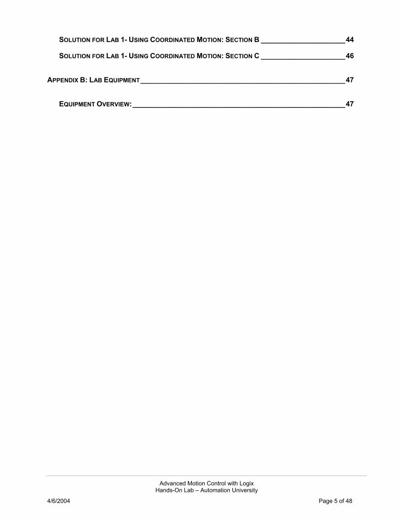
Lab Materials
For this Hands-On lab, we have provided you with the following materials that will allow you to complete the labs in this workbook.
Hardware
This hands-on lab uses the following hardware:
The ControlLogix Coordinated Demo case (Catalog No. 1796-CL11) (1) 1756-A10/A chassis with a 1756-PA72 power supply (2) 1756-L1 processors in slots 1 and 3 (2) 1756-OB16D 16 Point 19.2V - 30VDC diagnostic output modules in slots 0 and 4 (1) 1756-IB16D 16 Point 10V - 30VDC diagnostic input module in slot 2 (1) 1756-M08SE SERCOS Interface module in slot 5 (1) 1756-ENBT communication module in slot 6 (1) 1756-OF6VI Isolated Analog (10V) output module in slot 7 (1) 1756-IF6I Isolated Analog Voltage/Current input module in slot 8 (1) 1756-MO2AE Analog Encoder servo module in slot 9 (1) Ethernet Cross-over cable (1) 1747-CP3 or 1756-CP3 serial cable (9-pin female to 9-pin female null modem cable)
The Kinetix 6000 Demo case (Catalog No. 1796-K6K) (1) 2094-AC09-M02 Kinetix 6000 Integrated Amplifier Module (1) 2094-AM01 Kinetix 6000 Amplifier Module (2) MPL-A310P-M Motors (Absolute high resolution feedback devices)
Software
This hands-on lab uses the following software:
RSLogix 5000 Professional V12.02 (Cat.# 9324RLD700ENE) RSLinx Professional V2.42 (Cat.#9355WABENE)

Advanced Motion Control with Logix Hands-On Lab – Automation University
4/6/2004 Page 9 of 48
Files
This hands-on lab uses the following files:
Lab1_Start.ACD Lab1_SectionB.ACD Lab1_SectionC.ACD Lab2_Start.ACD Lab3_Master.ACD Lab3_AuxController.ACD
These files are located in the folder AdvancedMotion, located at the following path: C:\RSLogix 5000\Projects Note: This folder is also available via the Desktop shortcut of the same name.
Document Conventions
Throughout this workbook, we have used the following conventions to help guide you through the lab materials.
This style or symbol: Indicates: Words shown in bold italics (e.g., RSLogix 5000 or OK)
Any item or button that you must click on, or a menu name from which you must choose an option or command. This will be an actual name of an item that you see on your screen or in an example.
Words shown in Courier text, enclosed in single quotes (e.g., 'Controller1')
An item that you must type in the specified field. This is information that you must supply based on your application (e.g., a variable). Note: When you type the text in the field, remember that you do not need to type the quotes; simply type the words that are contained within them (e.g., Controller1).
✒ FYI The text that follows this symbol is supplemental information regarding the lab materials, but not information that is required reading in order for you to complete the lab exercises. The text that follows this symbol may provide you with helpful hints that can make it easier for you to use this product.
Note: If the mouse button is not specified in the text, you should click on the left mouse button.

Advanced Motion Control with Logix Hands-On Lab – Automation University
4/6/2004 Page 11 of 48
Lab 1: Understanding Coordinated Motion (30 mins.)
About This Lab
In this lab, we will introduce you to Multi-axis Coordinated Motion. Coordinated Motion is the ability to profile motion in 1-3 dimensions using linear or circular interpolation.
In this lab you will:
Create a new controller file Review and use the Coordinated Motion Linear instruction (MCLM)
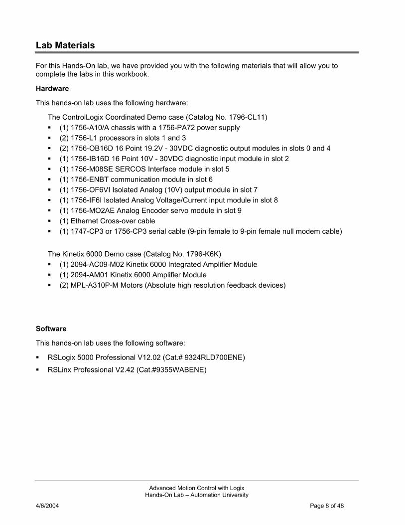
During this lab you will use the Kinetix 6000 two axis servo drive to demonstrate the RSLogix 5000 coordinated motion feature.
The demo is setup in the following manner:
Y Axis
X Axis The demo is simulating an X-Y table where the Y axis is linked to the X axis mechanically, the “Dot” symbol represents a tool/head that can rotate in the 2 dimensions of X and Y from (0, 0) to end travel of (8, 8):
Advanced Motion Control with Logix Hands-On Lab – Automation University
4/6/2004 Page 12 of 48
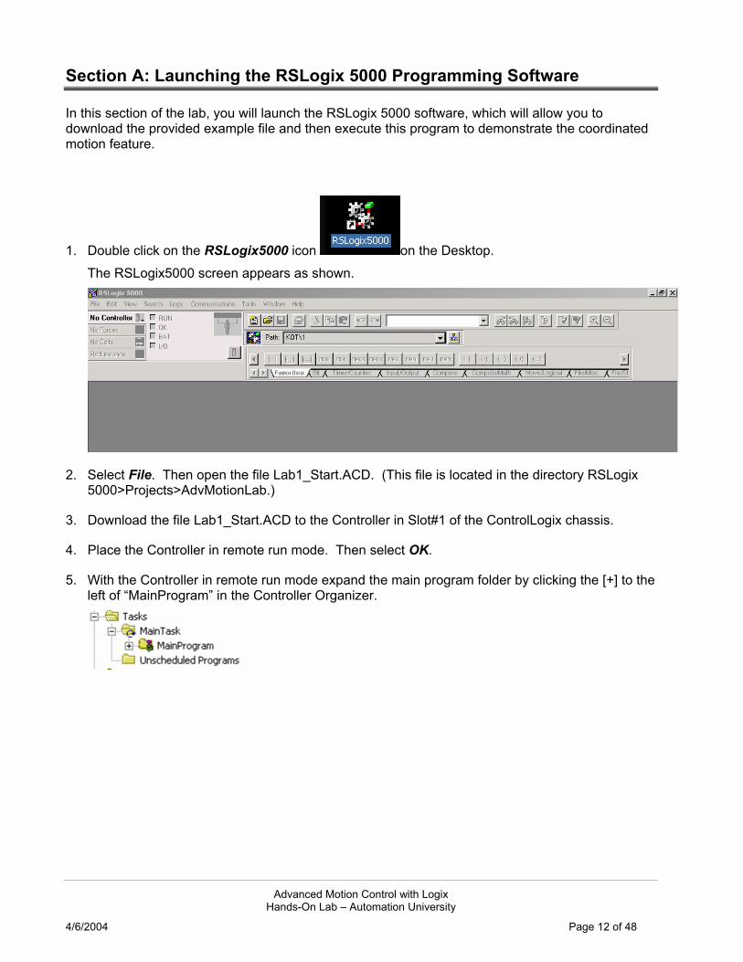
Section A: Launching the RSLogix 5000 Programming Software
In this section of the lab, you will launch the RSLogix 5000 software, which will allow you to download the provided example file and then execute this program to demonstrate the coordinated motion feature.
1. Double click on the RSLogix5000 icon on the Desktop. The RSLogix5000 screen appears as shown.
2. Select File. Then open the file Lab1_Start.ACD. (This file is located in the directory RSLogix 5000>Projects>AdvMotionLab.)
3. Download the file Lab1_Start.ACD to the Controller in Slot#1 of the ControlLogix chassis.
4. Place the Controller in remote run mode. Then select OK.
5. With the Controller in remote run mode expand the main program folder by clicking the [+] to the left of “MainProgram” in the Controller Organizer.

Advanced Motion Control with Logix Hands-On Lab – Automation University
4/6/2004 Page 13 of 48
The Controller Organizer provides easy navigation through the application file tasks, programs, routines and tags. Here is the Controller Organizer view you should see now.
✒ FYI
The Controller Organizer is a graphical representation of the contents of your controller file. This display consists of a tree of folders and files that contain all of the information about the programs and data in the current controller file. The default main folders in this tree are:
Controller File Name - contains controller-scoped tags, controller fault handler and the power up handler.
Tasks – any tasks are shown in this folder. Each task shows its own programs with ladder routines and program-scoped tags.
Trends - trends are shown in this folder. Data Types - shows predefined and user-defined data types. User-defined data
is created in this folder. I/O Configuration - contains the information about the hardware configuration of
this controller file. It holds a hierarchy of modules with which the controller is configured to communicate.
In front of each folder, there is a square containing a + sign or a - sign. The + sign indicates that the folder is closed. Click on it to expand the tree display and display the files in the folder. The - sign indicates that the folder is already open and its contents are visible.

Advanced Motion Control with Logix Hands-On Lab – Automation University
4/6/2004 Page 14 of 48
6. Open the main routine by selecting the icon from the Controller organizer window and double-clicking. The routine will open as shown below.
7. Expand the Trends folder and then open the trend Coordinated_Motion by double clicking the trend name icon. The trend chart will appear.
8. Start the trend Coordinated_Motion by selecting the Run icon in the trend menu bar.

Advanced Motion Control with Logix Hands-On Lab – Automation University
4/6/2004 Page 15 of 48
9. We will now execute the application program to draw the traditional Allen-Bradley logo. Open the routine Watch window by using the ALT 3 shortcut. The watch window will appear at the bottom of the trend window. The program tags from the routine MainRoutine will be displayed.
✒ Viewing and Using the Watch window
The Watch window can also be opened & closed via the View heading on the Main Menu bar.
The Watch window is an aid for navigating tags contained in the currently open routine. The program tags can be accessed for setting and monitoring.
10. Using the Watch window scroll down the available program tags and find the tag StartDraw
11. Set the StartDraw tag high by selecting the value window and typing ‘1’ then pressing Enter on the keyboard. The trend will begin to display the X and Y axes positions as commanded in the application file. The Allen Bradley Logo will begin to appear. The complete draw cycle will take approx. 65 seconds at the default speed setting.
12. Take a look at the Logix program which is executing this coordinated motion profile. Open the MainRoutine. Here you will see the sequential program structure which is controlling the X-Y table program for this demo.

Advanced Motion Control with Logix Hands-On Lab – Automation University
4/6/2004 Page 16 of 48
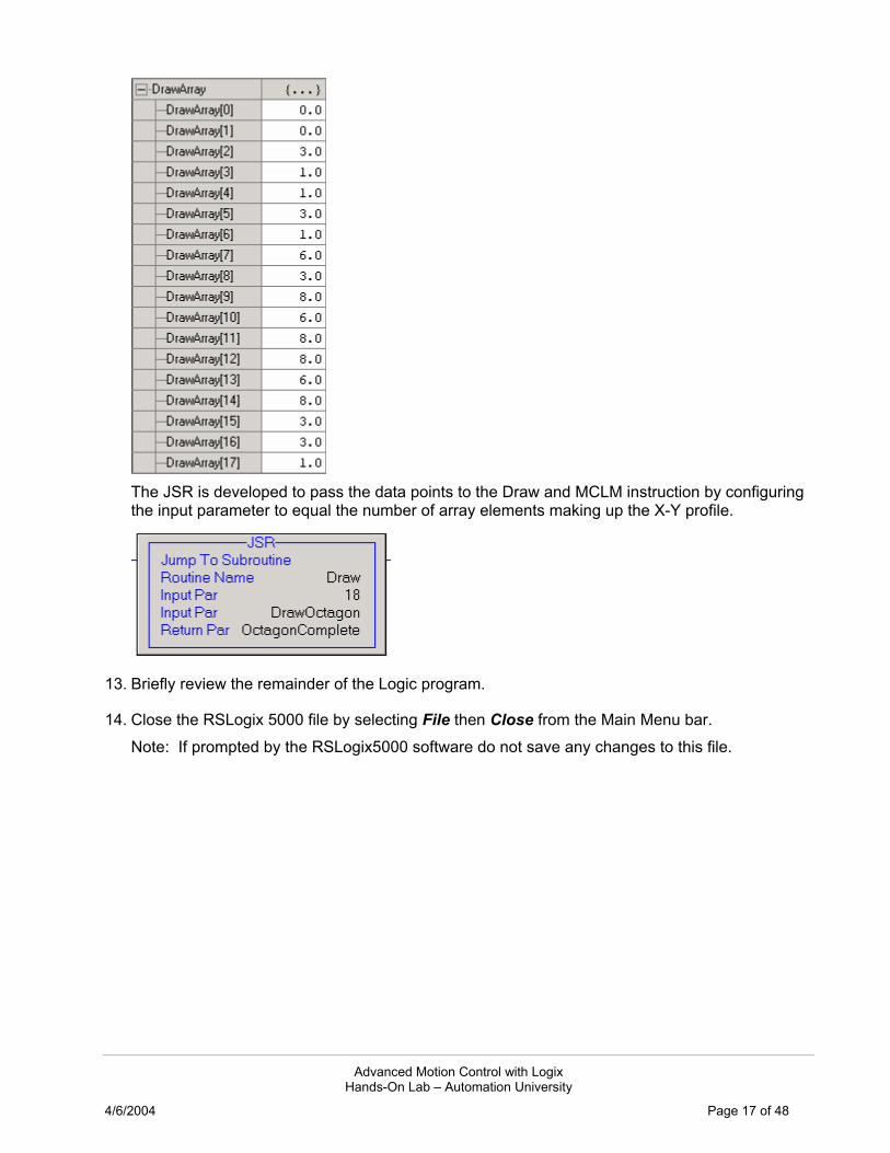
The main routine is made of multiple Jump to Subroutine (JSR) calls with one for each letter or segment of the logo profile. These subroutines pass data point values to the routine Draw. The routine Draw is a small subroutine which has several rungs of state logic to increment a counter and index through the number of data point values (in the tag DrawArray) that were passed into this routine. The data point values are stored in arrays that make up the desired profile or segment and are used in the Motion Coordinated Linear Move (MCLM) instruction. The MCLM instruction is used to move/coordinate the 2 servo axes in their own dimension of the coordinate system. The axes will move in an absolute manner (this is in our boundaries of end travel of 8 units) at the programmed speed of the instruction. The input and output parameters of the JSR instruction are used to pass in the data point values and then pass out the completion of the individual segment in process. For Example, if you wanted to draw the shape of an Octagon on this X-Y table, you would have the following eight data points to pass.
This would give us a DrawArray of nine point pairs, the eight points shown above and the starting point of (0, 0). In the MCLM instructions, use this array to populate the Position operand; this array in Logix is all the data points used in the instruction. This array is seen in the Controller tag database as: For the first point (X1, Y1) we use DrawArray[0] for X1 and DrawArray[1] for Y1 then it continues through the final data point values.
Advanced Motion Control with Logix Hands-On Lab – Automation University
4/6/2004 Page 17 of 48
The JSR is developed to pass the data points to the Draw and MCLM instruction by configuring the input parameter to equal the number of array elements making up the X-Y profile.
13. Briefly review the remainder of the Logic program.
14. Close the RSLogix 5000 file by selecting File then Close from the Main Menu bar. Note: If prompted by the RSLogix5000 software do not save any changes to this file.

Advanced Motion Control with Logix Hands-On Lab – Automation University
4/6/2004 Page 18 of 48
Section B: Correcting an application file with a motion profile error (Optional)
In this section, you will be given a pre-configured coordinated motion application file which contains errors in the profile. Your task is to locate and correct any errors.
The pre-configured file contains a profile that will generate a picture of 2 different size boxes on the X-Y area. The picture below shows the shape and location of the two boxes as they should appear.
In the file Lab1_SectionB.ACD the profile information contains errors. The sequential program structure is correct for this application.
Box 1 (3x3) Fig. 1 Box 2 (2x6)
1. From the File menu, choose Open then select the file Lab1_SectionB.ACD and select Open. The RSLogix5000 application file will open.
2. Download the file to the controller in Slot#1. Place the controller in Remote Run.
3. Open the main routine by selecting the icon from the Controller organizer window and double-clicking.
4. Expand the Trends folder and open the trend Boxes.
5. Start the trend Boxes by selecting the Run icon in the trend menu bar.
6. Open the routine Watch window by using the ALT 3 shortcut.
7. Using the Watch window scroll down the available program tags and find the tag StartDraw.

Advanced Motion Control with Logix Hands-On Lab – Automation University
4/6/2004 Page 19 of 48
8. Set the StartDraw tag high by selecting the value window and typing ‘1’ then pressing Enter on the keyboard. The X-Y profile will began to be executed with the trend as shown below.
9. Locate and correct the errors in the application file for the profile above. How many errors are present? Where? Note: If you have any questions check Appendix A for solutions and hints, also ask the instructor if you need assistance.
10. Save your file as Lab1_SectionB_End.ACD.
11. Download your file to the Controller in Slot#1 and run the draw cycle to complete the proper trend. (Shown earlier in Fig. 1)
12. Close the RSLogix 5000 file by selecting File then Close from the Main Menu bar. Note: If prompted by the RSLogix5000 software do not save any changes to this file.
Advanced Motion Control with Logix Hands-On Lab – Automation University
4/6/2004 Page 20 of 48
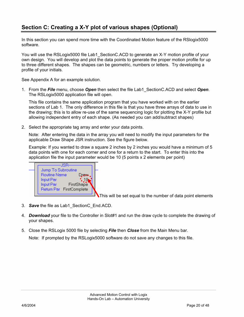
Section C: Creating a X-Y plot of various shapes (Optional)
In this section you can spend more time with the Coordinated Motion feature of the RSlogix5000 software.
You will use the RSLogix5000 file Lab1_SectionC.ACD to generate an X-Y motion profile of your own design. You will develop and plot the data points to generate the proper motion profile for up to three different shapes. The shapes can be geometric, numbers or letters. Try developing a profile of your initials.
See Appendix A for an example solution.
1. From the File menu, choose Open then select the file Lab1_SectionC.ACD and select Open. The RSLogix5000 application file will open. This file contains the same application program that you have worked with on the earlier sections of Lab 1. The only difference in this file is that you have three arrays of data to use in the drawing; this is to allow re-use of the same sequencing logic for plotting the X-Y profile but allowing independent entry of each shape. (As needed you can add/subtract shapes)
2. Select the appropriate tag array and enter your data points. Note: After entering the data in the array you will need to modify the input parameters for the applicable Draw Shape JSR instruction. See the figure below. Example: If you wanted to draw a square 2 inches by 2 inches you would have a minimum of 5 data points with one for each corner and one for a return to the start. To enter this into the application file the input parameter would be 10 (5 points x 2 elements per point)
This will be set equal to the number of data point elements
3. Save the file as Lab1_SectionC_End.ACD.
4. Download your file to the Controller in Slot#1 and run the draw cycle to complete the drawing of your shapes.
5. Close the RSLogix 5000 file by selecting File then Close from the Main Menu bar. Note: If prompted by the RSLogix5000 software do not save any changes to this file.

Advanced Motion Control with Logix Hands-On Lab – Automation University
4/6/2004 Page 21 of 48
Lab 1 Section C (Optional):
Advanced Motion Control with Logix Hands-On Lab – Automation University
4/6/2004 Page 22 of 48
Lab 2: Coordinated Motion Application (45 mins.)
About This Lab
In this lab, you will complete an example application using some of the newest features of the RSLogix5000 software. Two of these new features are coordinated motion circular interpolation and position based outputs (MAOC instruction).
In this lab, you will:
Configure a coordinated motion circular interpolation instruction (MCCM) Configure and use a position based output in an application (MAOC)
Follow the steps below to complete Lab 2.
Application Example – Automated glue sealer for window frames.
This application is an extension of some of the items you have already seen possible with the RSLogix5000 software coordinated motion capability. A common application in the servo industry which uses coordinated motion is an X-Y table. The X-Y table could be a cutter for pattern making, an etching device (as we showed in lab 1) or a sealing device for product assembly.
In this lab we have decided to work on an application of a glue applicator machine used for window frame construction.
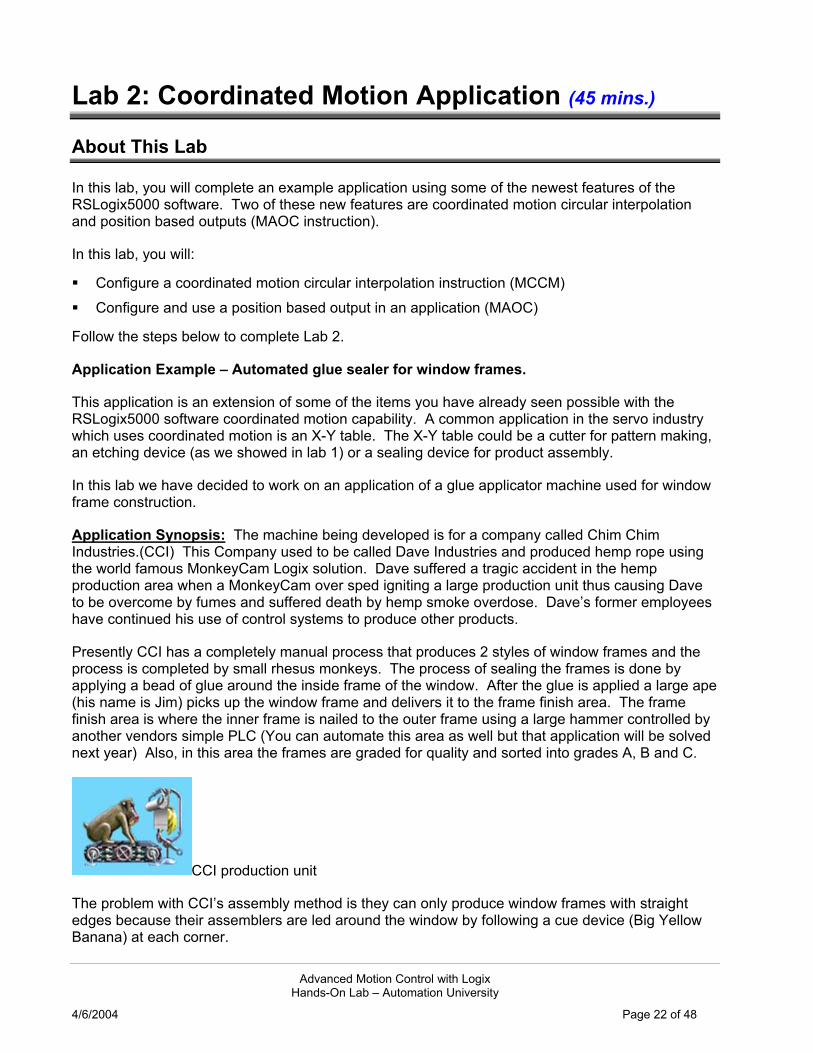
Application Synopsis: The machine being developed is for a company called Chim Chim Industries.(CCI) This Company used to be called Dave Industries and produced hemp rope using the world famous MonkeyCam Logix solution. Dave suffered a tragic accident in the hemp production area when a MonkeyCam over sped igniting a large production unit thus causing Dave to be overcome by fumes and suffered death by hemp smoke overdose. Dave’s former employees have continued his use of control systems to produce other products.
Presently CCI has a completely manual process that produces 2 styles of window frames and the process is completed by small rhesus monkeys. The process of sealing the frames is done by applying a bead of glue around the inside frame of the window. After the glue is applied a large ape (his name is Jim) picks up the window frame and delivers it to the frame finish area. The frame finish area is where the inner frame is nailed to the outer frame using a large hammer controlled by another vendors simple PLC (You can automate this area as well but that application will be solved next year) Also, in this area the frames are graded for quality and sorted into grades A, B and C.
CCI production unit
The problem with CCI’s assembly method is they can only produce window frames with straight edges because their assemblers are led around the window by following a cue device (Big Yellow Banana) at each corner.
Advanced Motion Control with Logix Hands-On Lab – Automation University
4/6/2004 Page 23 of 48
Also, the quality of the window seals is very poor due to the speed at which the glue is applied, on short stretches the glue bead becomes very heavy due to the assembler slowing down and on long stretches the glue bead becomes very thin due to the assembler speeding up.
CCI would like to improve the quality of their windows, add a hinge punch-out and begin production of a round framed window.
Section A: Create an application program
In this section you will use the RSLogix5000 software to create an application file using the Unscheduled programs feature of RSLogix 5000 to modify a pre-configured file. To modify the RSLogix 5000 file Lab2_Start.ACD:
1. Choose Open from the file menu. Then select the file Lab2_Start.ACD and select Open. The RSLogix5000 application file will open.
2. Expand the main program folder by clicking the [+] to the left of MainProgram in the Controller Organizer.
3. Open the main routine by selecting the icon from the Controller organizer window and double-clicking. This file contains the application program that uses the linear coordinated motion instruction to produce two window frames, square shape and triangle shape. You will complete the necessary programming to add a circular pattern and add a position based output to run the hinge punch mechanism.
4. Expand the Unscheduled Programs folder by clicking the [+] to the left of the heading Unscheduled Programs in the Controller Organizer. Then Expand the task Program_Library.
The routine called Library contains some of the sequential programming you will need to add the new circular window frame style to the machine.
✒ Using Unscheduled Programs
As you can see here this is a powerful feature of the RSLogix5000 software, any unscheduled programs will be placed here but can easily be re-applied to any active task by using the scheduler wizard in the Task properties view.
You can also use the Unscheduled Programs as a storage location for commonly used application code samples. The unscheduled programs will still be subject to the verification rules of the controller so you cannot save coding samples here which contain verification errors.
5. Open the Library routine by selecting the icon from the Controller organizer window then right mouse click and select Open. (can also open by double-clicking the icon) The four rungs seen here have been created to aid you in developing the solution.

Advanced Motion Control with Logix Hands-On Lab – Automation University
4/6/2004 Page 24 of 48
6. Use the keystroke CTRL A to select all four of the rungs.
7. Copy all the selected items to the windows clipboard by using the keystroke CTRL C.
✒ Editing Options
As you have probably seen when using the RSlogix5000 software there are many different options to perform the same task. We could also have used the Main Menu “Edit” heading to select and copy all the rungs.
8. Return to the routine MainRoutine by selecting from the Controller Organizer. As a quick shortcut you can use the open routine headings to go to any routine, this is at the bottom of the main application window.
9. Scroll down the present rungs until you are on the rung 12 heading. Use the keystroke CTRL V to paste in the copied rungs. Note: Rungs 13-17 have now been added to this routine for the assembly process.
Section B: Create a MCCM instruction In this section you will use the RSLogix5000 software to create an application file to generate an X-Y circular motion profile.
1. Go to rung 15 of the MainRoutine. You will see that there is an OTE instruction present as a place holder for where we will add the Motion Coordinated Circular Move (MCCM).
2. Select the OTE instruction body by placing the cursor over the instruction element, double click the left mouse and change the instruction to a MCCM then press enter. The Edit will appear as below until you press enter.
Note: All the operand tags have been been created in the Controller tag database to aid your creation of this application file. The MCCM will be setup and configured to operate in an absolute mode and execute a profile as defined in the array CircleArray. Select the operand setting for the Coordinate System to set to the tag CSXY by using the drop down menu item. The coordinate system CSXY contains the mapping of axes and configuration information for how our Cartesian coordinate system will operate.

Advanced Motion Control with Logix Hands-On Lab – Automation University
4/6/2004 Page 25 of 48
The Coordinate System is capable of being configured in different relationships:
We are using the 2 Axis Cartesian System. The coordinate system is configured under the Motion Group heading.
This 2 axis system has an X-Y table with a glue nozzle tied to the end of the Y servo axis. The Y axis is mechanically linked to the X axis for travel in the X dimension.
Glue Applicator
3. Select the tag “MCCM_Draw1” for the Motion Control operand setting.
4. Enter ‘0’ for the Move Type setting because you want the profile done in absolute position units.
5. Select the first element of the tag CircleArray for the Position operand.
Before executing this instruction we will need to populate the tag CircleArray with the appropriate position data to perform the MCCM as desired on our circular window frame.

Advanced Motion Control with Logix Hands-On Lab – Automation University
4/6/2004 Page 26 of 48
6. Select More to expand the MCCM instruction.
7. Enter a Circle Type of 2; this will perform a MCCM instruction using the Radius option of the Via/Center/Radius types. Next, select the first element of the tag Radius.
8. Complete the operand settings as shown below.
9. Select the operand for Position, “CircleArray[0]”, then right-mouse click and select “Monitor CircleArray[0]”
10. Enter a value of 2.0 in CircleArray element 0 and a value of 4.0 in CircleArray element 1. These values will now be used to create the circular profile in the MCCM instruction.
11. Scroll down the Controller tag database and locate the array tag Radius. Expand the tag and enter a value of 2.0 in Radius element 0. Note: You have completed the setup for a Circular profile of the X-Y assembly with the profile being executed in the counter clockwise direction with a radius of 2 units. The tag CircleArray defines an X and Y data point that the profile will travel through, therefore when this profile executes it will start at position (0,0) and travel CCW through position (2,4).
Running Profile
12. Save the file as Lab2_SectionB.ACD.

Advanced Motion Control with Logix Hands-On Lab – Automation University
4/6/2004 Page 27 of 48
13. Download the file to the Controller in Slot#1. Place the Controller in Remote Run. Select OK.
14. Expand the Trends folder and open the trend WindowSealer.
15. Start the trend by selecting the Run icon in the trend menu bar.
16. Run the X-Y profile by using the ControlLogix digital input pushbuttons. Note: Steps to executing the profile include: Selecting a frame style to create, use the demo inputs DI#0 = Circular DI#4 = Triangle DI#8 = Square Selecting DI#3 (Start_Production) to run profile.
Section C: Using a MAOC Instruction In this section you will use the Motion Arm Output Cam (MAOC) instruction to execute a position based output. The output to execute is the solenoid for the hinge punch mechanism. The MAOC instruction is used to control outputs on and off based on position of the motion axis. The motion axis can be either a real (physical axis of type Axis_Servo or Axis_Servo_Drive) or software only axis (type of Axis_Virtual). There are two hinge positions located on the frame @ position A and position B. Position A is on = 1.0 and off = 1.5. Position B is on = 2.5 and off = 3.0.
1. Go offline from the Controller.
2. In the Controller Organizer go to the MainRoutine.
3. Scroll down the MainRoutine and highlight the End rung heading then right mouse click and select Add Rung.
4. Add 2 instructions to this rung, a XIC and a MAOC.
Your new rung should appear as below:

Advanced Motion Control with Logix Hands-On Lab – Automation University
4/6/2004 Page 28 of 48
5. Select the XIC tag name and then select the tag Hinges_On from the tag window to complete this instruction.
6. Select the appropriate tag for each operand to complete the MAOC instruction as shown below:
Output Cam Ellipsis When this MAOC executes the CAM will activate or arm when the X axis moves in the positive direction past the Axis Arm and Cam Arm positions. This cam will only be active one time through the Cam Start and End Position window, therefore when the X axis has moved past the Cam End Position the MAOC will go to the state of Process Complete. (.PC)
7. You now set when you want the output to execute by configuring the MAOC. Click on the ellipsis next to the Output Cam tag operand.
The MAOC editor will open as shown:
Output# Position Window Output Cam bit#
✒ Output Cams
The ControlLogix system will allow up to 8 output cams per Axis, the output cams are called Execution Targets. The Execution Targets are configured in the Motion Planner folder of the axis properties on an axis.
Each output cam can contain a maximum of 32 output cam bits.

Advanced Motion Control with Logix Hands-On Lab – Automation University
4/6/2004 Page 29 of 48
This is how Axis “X” was pre-configured for this lab.
8. We want to setup an output to turn on two times to set the hinge punch mechanism. This will
occur during the X-Y profile. Select the Insert tool on the main menu bar.
9. Select any area in the position window next to bit 0 and click to add the output turn on/turn off settings.
10. Repeat steps 7 and 8 to add another output cam bit. The Output Cam Editor should appear somewhat as below with 2 output cam bits installed on Output Bit#0.
11. If you recall from the beginning of this lab section we want the hinge punch output to turn on/off at the positions in table 1. Adjust the On (Left Position) and Off (Right Position) positions for each output cam to the desired settings. After entering the new position data click on the Zoom
to Fit icon to adjust your view of the profiles.
Table 1
Hinge Punch Output On
Off
Position A 1.0 1.5
Position B 2.5 3.0
Your Output Cam Editor should appear as below:
12. Select OK to exit the MAOC Cam Editor.

Advanced Motion Control with Logix Hands-On Lab – Automation University
4/6/2004 Page 30 of 48
13. Now we also need a method to turn off the output cam if needed. Select the rung 18 heading and then select the Branch icon, using the mouse drag the branch right end just past the MAOC instruction.
14. On the new branch level in rung 18 add three new instructions; an XIO, XIC and MDOC.
15. Select the XIO instruction and assign the tag Hinges_On to it using the tag editor.
16. Select the XIC instruction and assign the tag attribute MAOC_Control.IP to it using the tag editor.
17. Complete the MDOC instruction operands as shown below:
Your completed rung 18 should appear as shown:
18. Save the file as Lab2_SectionC.ACD.
19. Download the file to the Controller in Slot#1. Place the Controller in Remote Run. Select OK.
20. Open the routine Watch window by using the ALT 3 shortcut.
21. Expand the Trends folder and open the trend WindowSealer.
22. Start the trend WindowSealer by selecting the Run icon in the trend menu bar.
23. Run the Coordinated Motion profile. Notes: Here are the steps to execute profile:
1. Select frame style to create, DI#0 = Circular, DI#4 = Triangle and DI#8 = Square. 2. If want to create hinge punch out then turn on DI#12 (Hinges_On).

Advanced Motion Control with Logix Hands-On Lab – Automation University
4/6/2004 Page 31 of 48
3. Select DI#3 (Start_Production) to run profile.
Square Window Frame with hinge punch out installed

Advanced Motion Control with Logix Hands-On Lab – Automation University
4/6/2004 Page 32 of 48
Lab 3: Using Event Based Tasks (30 mins.)
About This Lab
In this lab, you will:
Use an Event Based Task in an application. Compare the performance of a Periodic, Event and Motion Task. Use OPC topic and Microsoft Excel to analyze data from Logix controller
Event Based Task – Lab Overview
Production Overview: This is where the produced frames get inspected, graded for workmanship and then sorted/stacked for distribution. The inspection system conveyor is run after finishing a large batch of frames but at full production, the inspection/sortation system can handle up to 600 frames a minute. That can create some serious problems for a control system with a production rate that approaches 100ms per frame.
Architecture: A Logix servo system is installed running the conveyor line, Jim and his crew loads the system and let the inspection system determine the frame grading. A high speed vision inspection system tells a master controller where the next frame needs to be sorted (grade A, B, or C). The control system then needs to sort the frames in the appropriate stacks when the servo system reaches a fixed mechanical position.
The diverters themselves take 97ms to operate leaving the control system 3 ms per frame to determine that the axis has reached position and to fire the appropriate diverter. At this output an incremental stepping kind of machine would be impractical so the main servo runs at continuous speed thru the entire application. The delays for acceleration/deceleration at each part would greatly increase the production time as well as the damage high acceleration rates could have on the windows parts.
Programming Overview:
In this lab we will be tackling the problem of firing the diverter in enough time to rout the frame to the proper grading stack without firing too early and re-routing a frame currently in the diverter
Grade C
Grade A
Grade B Diverter 97ms Response
Main Servo In Feed Belt
HighSpeed Frame Inspection System
Frame clears diverter 100 ms before next frame enters diverter

Advanced Motion Control with Logix Hands-On Lab – Automation University
4/6/2004 Page 33 of 48
shoot. Note: For the purposes of this lab we are assuming the vision data is getting to the control system early enough.
This demo case box is setup with the following:
Master Controller (Slot#1)
Aux. Controller (Slot#3)
DC Output Module (Slot#0)
SERCOS Module (Slot#5)
Because only one processor can own the SERCOS module, the master processor (Slot#1) is setup to run the motion of the conveyor system and then produce the actual watch position event thru a tag called Produced_WatchPos to the Aux. Controller.
The Lab3_Master.ACD application file contains:
The master processor is handling the following tasks. Review the appropriate logic.
Running the Servo at the machine line speed.
In the Main Task – Main Program – Motion_Jog routine, look at rung 1. This rung will constantly try to initiate a JOG at line speed anytime the axis is enabled and not currently homing.
Running a Servo Watch Position instruction.
In the Main Task – Main Program – Motion_Watch Routine, look at rung 0. This instruction is used for high-speed applications where you need to know when an axis crosses a known position. The instruction MAW (motion arm watch) actually passes the watch data down to the servo card (in our case the SERCOS Drive) where it waits until the axis position is reached (configured for once every 10 revs). At that point it fires an immediate input to the processor to identify the watch is PC (process complete). The offloading of this task to the motion controller provides a huge improvement in performance. The communications to the processor for the watch position complete is totally asynchronous, which means you don’t have to wait for motion planner execution, RPI I/O updates, or ladder execution. You can arm the watch position in the continuous task since its actual evaluation is done on the SERCOS drive.
Capture the CST time.
Captures the CST time at which the master processor identified the watch position event occurred. MasterAxisWatch Task – EventCycle Program – TheMainEvent Routine, look at rung 3. This is an event task so this code only runs once when the event occurs. The event that triggers this code is the axis watch position reached. You will be using this data, from the GSV instruction, to compare our student processors performance. Note: The CST is a master clock that is used by all modules in the same backplane.
This rung also produces a tag that identifies the watch position is complete using an IOT (immediate out instruction). This assures the Aux. Controller gets watch position information in a timely manner.
Advanced Motion Control with Logix Hands-On Lab – Automation University
4/6/2004 Page 34 of 48
Runs the OB16 output card.
The master processor will set the DO0 light to give you a visual indication that the event (axis position watch) occurred.
Section A: Using a Periodic Task
Prior to revision 12 of RSLogix 5000, the way to watch for high speed events on a system was using a frequently executing periodic task. By setting the periodic task up to execute every 2 ms or so, we are able to evaluate the status of an input and make decisions based on that. The continuous task is not a good place to evaluate high speed inputs as its execution time is typically dependent on all other user tasks.
1. Double click on the RSLogix5000 icon on the Desktop.
2. From the File menu, choose Open then select the file Lab3_Master.ACD and select Open. The RSLogix5000 application file will open which contains the main control for the inspection system.
3. Download the file to the Controller in Slot#1. Place the Controller in Remote Run. Select OK. The Kinetix 6000 axis will begin to move at a continuous speed of 20 revs/sec to simulate the main conveyor movement. (The Kinetix 6000 AM01 is not used in this lab)
4. Go back to the Desktop and again double click on the RSLogix5000 icon to launch another instance of the RSLogix5000 software.
5. From the File menu, choose Open then select the file Lab3_AuxController.ACD and select Open. The RSLogix5000 application file will open which contains the control for the auxiliary system. Review the application code. You have a main task which handles data collection, and a fast periodic task that watches for the watch position tag to transition, and grabs the current CST time. Additionally you are using the Kinetix axis data from the main controller to gear too a virtual axis which will create some task overhead for this controller. This simulates an application with produced/consumed tags on the controller backplane.
6. Download the file to the Controller in Slot#3. Place the Controller in Remote Run. Select OK. Now to check the performance of the system we will use a Microsoft Excel spreadsheet to analyze the data being passed from the Master to Aux. Controllers.
7. Launch the Microsoft Excel software, go to Start > Programs > Microsoft Excel.
8. Open the excel file KOT_MotionLab.xls (This file can located in the desktop folder AdvMotion Lab)

Advanced Motion Control with Logix Hands-On Lab – Automation University
4/6/2004 Page 35 of 48
9. Select Yes to Update Linked Information. Note - This spread sheet links to the master controller to acquire the CST time at which the actual MAW event occurred, it also links to the Aux. Controller to acquire the CST time at which this controller recognized the event. This data is being acquired through OPC topics with RSLinx.
10. Monitor the System Repeatability chart in the excel spreadsheet. Note: This graph shows the time difference between when the event occurred, and when your processor actually identified the event occurred (in micro seconds).
11. From the RSLogix5000 online view with the program Lab3_Aux.Controller.ACD go to the Controller Organizer and locate the Task called PeriodicTask
12. Right Mouse click on the MainPeriodic program in the Periodic Task and select Properties, then select the tab Configuration.
Note: The scan times on this screen identify how much time the Aux. Controller spends to actually execute the Periodic program ladder logic. This task takes about 150us (max.) to run with an average scan of approx.25us.
13. Select OK to close the properties window.
14. From the Controller Organizer select the PeriodicTask heading then right mouse click and select Properties. Select the Monitor tab.

Advanced Motion Control with Logix Hands-On Lab – Automation University
4/6/2004 Page 36 of 48
Note: The times on shown are elapsed time. That means the task starts executing and the clock starts, the task finishes and the clock stops. This periodic task is setup to run every 2ms. If you look at the max elapsed scan time you notice it is significantly larger than the 200us time you saw for a max on the actual program execution. Since you know the program only takes about 200us to execute worst case, you can deduce something is interrupting this task by about 0.5ms. 0.6 ms (max scan time) - 0.150ms (program scan time) = 0.45ms missing. The only thing in this processor that runs at a higher priority than this task (aside from some minimal overhead for the operating system to handle task switching), is the motion task itself.
15. From the Controller Organizer select the Motion Group tag Motion then right Mouse and select properties.
16. Select the Attribute tab.
Here is the performance for the Motion Group
Note: The max scan time for the motion group is around 0.4 ms. That means when the motion task executes (configured for every 5ms) the task executes for 400us. The motion task being the highest priority task in the controllogix system interrupts the periodic task for up to the 400us of time and you see this in the properties/performance of the periodic task.
17. Select OK to close the Motion Group Properties window.
Advanced Motion Control with Logix Hands-On Lab – Automation University
4/6/2004 Page 37 of 48
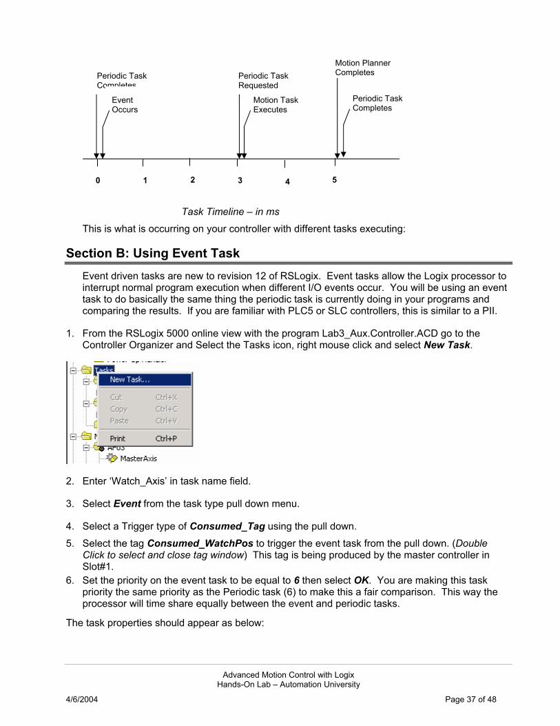
Task Timeline – in ms
This is what is occurring on your controller with different tasks executing:
Section B: Using Event Task Event driven tasks are new to revision 12 of RSLogix. Event tasks allow the Logix processor to interrupt normal program execution when different I/O events occur. You will be using an event task to do basically the same thing the periodic task is currently doing in your programs and comparing the results. If you are familiar with PLC5 or SLC controllers, this is similar to a PII.
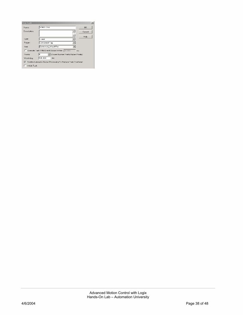
1. From the RSLogix 5000 online view with the program Lab3_Aux.Controller.ACD go to the Controller Organizer and Select the Tasks icon, right mouse click and select New Task.
2. Enter ‘Watch_Axis’ in task name field.
3. Select Event from the task type pull down menu.
4. Select a Trigger type of Consumed_Tag using the pull down. 5. Select the tag Consumed_WatchPos to trigger the event task from the pull down. (Double
Click to select and close tag window) This tag is being produced by the master controller in Slot#1.
6. Set the priority on the event task to be equal to 6 then select OK. You are making this task priority the same priority as the Periodic task (6) to make this a fair comparison. This way the processor will time share equally between the event and periodic tasks.
The task properties should appear as below:
Motion Planner Completes Periodic Task
Completes
Motion Task Executes
Event Occurs
Periodic Task Requested
Periodic Task Completes
0 1 2 3 4 5
Advanced Motion Control with Logix Hands-On Lab – Automation University
4/6/2004 Page 38 of 48

Advanced Motion Control with Logix Hands-On Lab – Automation University
4/6/2004 Page 39 of 48
Note: Here is the complete list for Event Task trigger options.
Event Trigger Types for RSLogix5000 (V12.01)
Axis Registration 1 High Speed registration input 1 locally on the motion card or on drive has just latched the current axis position.
Axis Registration 2 High Speed registration input 2 locally on the motion card or on drive has just latched the current axis position.
Axis Watch The axis has just crossed the assigned watch position
Consumed Tag * A consumed tag just changed value or its Sequence Count just changed.
EVENT instruction only Event instructions are available in ladder to trigger an event.
Module Input Data State Change * Input data on an input module has just changed or its Sequence Count changed.*
Motion Group Execution The motion planner just executed. Since the planner is always a higher priority than the event task, this event always occurs when the planner is complete.
There are a couple of different motion type events, one for watch position, and the other for registration input. There is also a one that looks at a module input point. While you would think you would want to use the motion Watch Position Event type, we do not in this case. The reason for that is that only the master processor in these chassis is able to own the motion card/drive combination which means only the master processor in this chassis can get the watch position event. What we have done for the purposes of this lab is have the master controller produce the watch event using an immediate out instruction.
7. On the event task named Watch_Axis , right mouse click and select New Program.
8. Enter a new program name ‘Event’ then select OK.
The new program will appear in your Controller Organizer.
9. Select the Event program then right mouse click and select New Routine.

Advanced Motion Control with Logix Hands-On Lab – Automation University
4/6/2004 Page 40 of 48
10. Enter a new routine named ‘EventRoutine’ and select OK.
11. Now you need to schedule this new routine to be the Main routine of the Event program. Select the Event program icon and right mouse click then select Properties.
12. Select the Configuration tab then select EventRoutine from the pull down menu for the main setting then select OK.
13. You now need to add some logic to identify when the actual event occurred. You will retrieve the CST time from the Controller. Open the routine EventRoutine.
14. Select the rung 0 heading and then right mouse click and select Add Ladder Element. Select the GSV instruction and then select OK.
15. Configure the GSV operands with the following settings:
16. Accept the edits to rung 0 by first selecting the accept pending program edits icon on the online toolbar.
Choose either circled icon.
17. Select Yes to accept pending edits.

Advanced Motion Control with Logix Hands-On Lab – Automation University
4/6/2004 Page 41 of 48
18. Select the test program edits icon and then select Yes to test program edits.
19. Select the assemble program edits icon and then select Yes to assemble pending edits.
20. Return to the Microsoft Excel sheet by using the windows shortcut, Alt Tab. Monitor the data and you will now see new values being populated for the event task (blue) vs. the periodic task (pink) Both the repeatability and the actual performance is superior to the periodic task even though both are running at priority 6 on the processor. The event task is running at a set time of when the event occurs where the Periodic task still has some deviation to scan updates. The impact on the Periodic task here is mostly the Motion Task which can be removed from the Aux. Controller.

Advanced Motion Control with Logix Hands-On Lab – Automation University
4/6/2004 Page 42 of 48
21. Return to the Aux. Controller RSLogix 5000 session by using the windows shortcut, Alt Tab.
22. Select the controller online icon and then select Go offline.
23. Go to the Controller Organizer and select the axis tag MasterAxis then select delete. Select Yes on the warning dialog to delete this axis.
24. Go to the Controller Organizer and select the axis tag VirtualAxis then select delete. Select Yes on the warning dialog to delete this axis.
25. Select the Motion Group tag Motion and select delete. Select Yes on the warning dialog to delete this motion group.

Advanced Motion Control with Logix Hands-On Lab – Automation University
4/6/2004 Page 43 of 48
26. Expand the MainProgram heading and select the MotionRoutine. Select delete to remove this routine from the MainProgram. Select Yes on the warning dialog to delete this routine.
27. One last item to remove in this controller. Open the MainRoutine then select the JSR in rung 1 and select delete.
28. Save the file as Lab3_AuxController_Complete.ACD.
29. Download the file to the Controller in Slot#3. Place the Controller in Remote Run. Select OK.
30. Return to the Microsoft Excel sheet by using the windows shortcut, Alt Tab.
Now you can see that without the Motion Task interrupting the lower level Periodic task there is improved performance.
31. Go offline from the controller and close the open RSLogix 5000 software sessions. Close the Microsoft excel file and then exit the software.

Advanced Motion Control with Logix Hands-On Lab – Automation University
4/6/2004 Page 44 of 48
Appendix A: Solutions
Solution for Lab 1- Using Coordinated Motion: Section B
There are two errors located in the file Lab1_SectionB.ACD. The errors are:
The first error is an incorrect home position on the X and Y axes. The home position is an axis setup parameter located in the Axis Properties. The correct home position for both axes should be 0. With the correct home position set the draw cycle starts the axes movement from the bottom left corner of the X-Y table at position (0, 0).
Incorrect Home Positions with resultant error on X-Y trend
Correct Home Positions
The second error is several incorrect data points for the motion profile. The tag DrawBoxes is a 32 element array containing the data points for the motion profile and in elements 13-16 there are incorrect data positions.

Advanced Motion Control with Logix Hands-On Lab – Automation University
4/6/2004 Page 45 of 48
Incorrect Motion Profile
Correct Motion Profile
DrawBoxes Data Points: Each dot is a data point in the array starting at Element 0. The X axis position is defined by the first element then the Y axis position is next and this continues through the final array element, Ex. For the first data point, DrawBoxes[0] is 0.0 and DrawBoxes[1] is 0.0, this is then X = 0 and Y = 0 (or known as the starting point or home)

Advanced Motion Control with Logix Hands-On Lab – Automation University
4/6/2004 Page 46 of 48
Solution for Lab 1- Using Coordinated Motion: Section C
The file Lab1_Shapes.ACD is an example completed file containing both letters and numbers. The picture below is the plotted profile.
The profile is executed with the data for each shape as shown below:
First Shape = A Second Shape = F Third Shape = 1
Advanced Motion Control with Logix Hands-On Lab – Automation University
4/6/2004 Page 47 of 48
Appendix B: Lab Equipment
Equipment Overview:
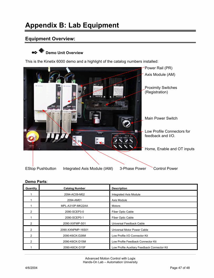
✒ Demo Unit Overview
This is the Kinetix 6000 demo and a highlight of the catalog numbers installed: Power Rail (PR) Axis Module (AM) Proximity Switches (Registration) Main Power Switch Low Profile Connectors for feedback and I/O. Home, Enable and OT inputs
EStop Pushbutton Integrated Axis Module (IAM) 3-Phase Power Control Power
Demo Parts: Quantity Catalog Number Description
1 2094-AC09-M02 Integrated Axis Module
1 2094-AM01 Axis Module
1 MPL-A310P-MK22AA Motors
2 2090-SCEP3-0 Fiber Optic Cable
1 2090-SCEP0-1 Fiber Optic Cable
2 2090-XXFMP-S01 Universal Feedback Cable
2 2090-XXNPMP-16S01 Universal Motor Power Cable
2 2090-K6CK-D26M Low Profile I/O Connector Kit
2 2090-K6CK-D15M Low Profile Feedback Connector Kit
1 2090-K6CK-D15F Low Profile Auxiliary Feedback Connector Kit
Advanced Motion Control with Logix Hands-On Lab – Automation University
4/6/2004 Page 48 of 48
The Input switches are wired to each Kinetix 6000 axis through the Low Profile connectors.
Switch IAM or AM I/O Connector
Enable IOD pin 2
Home IOD pin 5
Positive Overtravel IOD pin 8
Negative Overtravel IOD pin 11
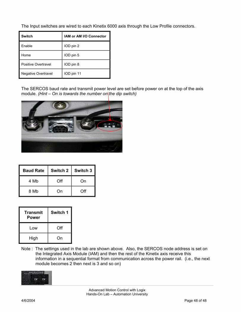
The SERCOS baud rate and transmit power level are set before power on at the top of the axis module. (Hint – On is towards the number on the dip switch)
Baud Rate Switch 2 Switch 3
4 Mb Off On
8 Mb On Off
Transmit Power
Switch 1
Low Off
High On
Note : The settings used in the lab are shown above. Also, the SERCOS node address is set on the Integrated Axis Module (IAM) and then the rest of the Kinetix axis receive this information in a sequential format from communication across the power rail. (i.e., the next module becomes 2 then next is 3 and so on)