Embed Size (px)
Citation preview
Veljko SamardzicME-215 Engineering Materials and Processes
Milling
Chapter 24
Veljko SamardzicME-215 Engineering Materials and Processes
24.1 Introduction
• Milling is the basic process of progressive
chip removal to produce a surface.
• Mill cutters have single or multiple teeth
that rotate about an axis, removing material.
• Milling can produce the desired surface
with a single or multiple passes.
• Milling lends itself easily to mass
production.

Veljko SamardzicME-215 Engineering Materials and Processes
24.2 Fundamentals of Milling
Processes
• Milling is classified in two categories:
– Peripheral milling: the surface is generated by
teeth located on the periphery of the cutter
body. The surface is parallel with the axis of
rotation of the cutter.
– End milling: also called facing milling, the
surface is generated is at a right angle to the
cutter axis. Material is removed by the
peripheral teeth and the face portion providing
finishing action.
Veljko SamardzicME-215 Engineering Materials and Processes
Peripheral Mills
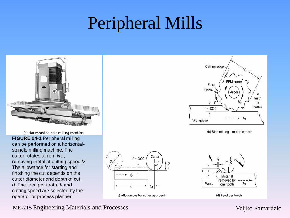
FIGURE 24-1 Peripheral milling
can be performed on a horizontal-
spindle milling machine. The
cutter rotates at rpm Ns ,
removing metal at cutting speed V.
The allowance for starting and
finishing the cut depends on the
cutter diameter and depth of cut,
d. The feed per tooth, ft and
cutting speed are selected by the
operator or process planner.

Veljko SamardzicME-215 Engineering Materials and Processes
Face Mills
FIGURE 24-2 Face milling is
often performed on a spindle
milling machine using a
multiple-tooth cutter (n 6
teeth) rotating Ns at rpm to
produce cutting speed V. The
workpiece feeds at rate fm in
inches per minute past
the tool. The allowance
depends on the tool diameter
and the width of cut.

Veljko SamardzicME-215 Engineering Materials and Processes
Vertical and Horizontal Cutters
FIGURE 24-3 Face milling
viewed from above with vertical
spindle-machine.
FIGURE 24-4 Slab or side
milling being done as a down
milling process with horizontal
spindle-machine.

Veljko SamardzicME-215 Engineering Materials and Processes
End Milling
FIGURE 24-5 End milling a step feature in a block using a flat-bottomed, end mill cutter in a vertical
spindle-milling machine. On left, photo. In middle, end view, table moving the block into the cutter. On
right, side view, workpiece feeding right to left into tool.

Veljko SamardzicME-215 Engineering Materials and Processes
Up Versus Down Milling
• Conventional milling is called up milling– The cutter rotates against the direction of feed of the
workpeice.
– The Chip is very thin at the beginning and increased along its length.
– The cutter tends to push the work along and lift it upwards from the table.
• Down milling the cutter rotation is the same as the direction of feed– The maximum chip thickness is at the point of tooth
contact with the work piece. Dulling the teeth more quickly
– The work piece is pulled into the cutter, eliminating any effects from looseness of the work table feed screw.

Veljko SamardzicME-215 Engineering Materials and Processes
Climbing versus Conventional
Mills
FIGURE 24-6 Climb cut or
down milling versus
conventional cut or up milling
for slab or face or end milling.

Veljko SamardzicME-215 Engineering Materials and Processes
24.3 Milling Tools and Cutters
• There are a variety of mills used, the most
common being face mills and end mills
– End mills are either HSS or have indexable
inserts (Figure 8)
– End Mills come in a variety of geometries
• Plain End Mills
• Shell End Mills
• Hollow End Mills

Veljko SamardzicME-215 Engineering Materials and Processes
Other Mill Cutter Types
• Face mills have indexable inserts along the periphery (Figure 7)
• Face Mills come in a variety of geometry (Figure 9)
– Center hole for arbor mounting
– Side mill (Figure 10)
– Staggered-tooth
– Straddle milling
– Interlocking slot cutters
– Slitting cutters

Veljko SamardzicME-215 Engineering Materials and Processes
Facing Mill
FIGURE 24-7 Conventional
face milling (left) with cutting
force diagram for Fc (right)
showing the interrupted nature
of the process. (From Metal
Cutting Principles, 2nd ed.,
Ingersoll Cutting Tool Company.)

Veljko SamardzicME-215 Engineering Materials and Processes
Typical Cutter Problems

Veljko SamardzicME-215 Engineering Materials and Processes
End Mill Geometry
FIGURE 24-8 Solid end mills are often coated. Insert
tooling end mills come in a variety of sizes and are
mounted on taper shanks.

Veljko SamardzicME-215 Engineering Materials and Processes
Facing Mill Geometry
FIGURE 24-9 Face mills come
in many different designs using
many different insert geometries
and different mounting arbors.

Veljko SamardzicME-215 Engineering Materials and Processes
Side Milling
FIGURE 24-10 The side-
milling cutter can cut on
sides and ends of the teeth,
so it makes slots or
grooves. However, only a
few teeth are engaged at
any one point in time,
causing heavy torsional
vibrations. The average
chip thickness, hi, will be
less than the feed per
tooth, ft . The actual
feed per tooth fa will be
less than feed per tooth
selected, Ft .

Veljko SamardzicME-215 Engineering Materials and Processes
Arbor Milling
FIGURE 24-11 Arbor (two views) used on a horizontal-
spindle milling machine on left. On right, a gangmilling
setup showing three side-milling cutters mounted on an
arbor (A) with an outboard flywheel (B).

Veljko SamardzicME-215 Engineering Materials and Processes
Helical Mills
FIGURE 24-12 The chips are
formed progressively by the
teeth of a plain helical-tooth
milling cutter during up milling.

Veljko SamardzicME-215 Engineering Materials and Processes
Shaped Cutters
• Form Relieved Cutters are used when
intricate shapes are needed.
• T-slot cutters are used to produce slots in
material. An end mill is use first to produce
the initial groove
• A wooddruf keyseat cutter is used to
produce a slot in a shaft and come in
standard sizes
• Fly cutters are single toothed face mill
cutters, with adjustable radii.
Veljko SamardzicME-215 Engineering Materials and Processes
Relieved Cutter
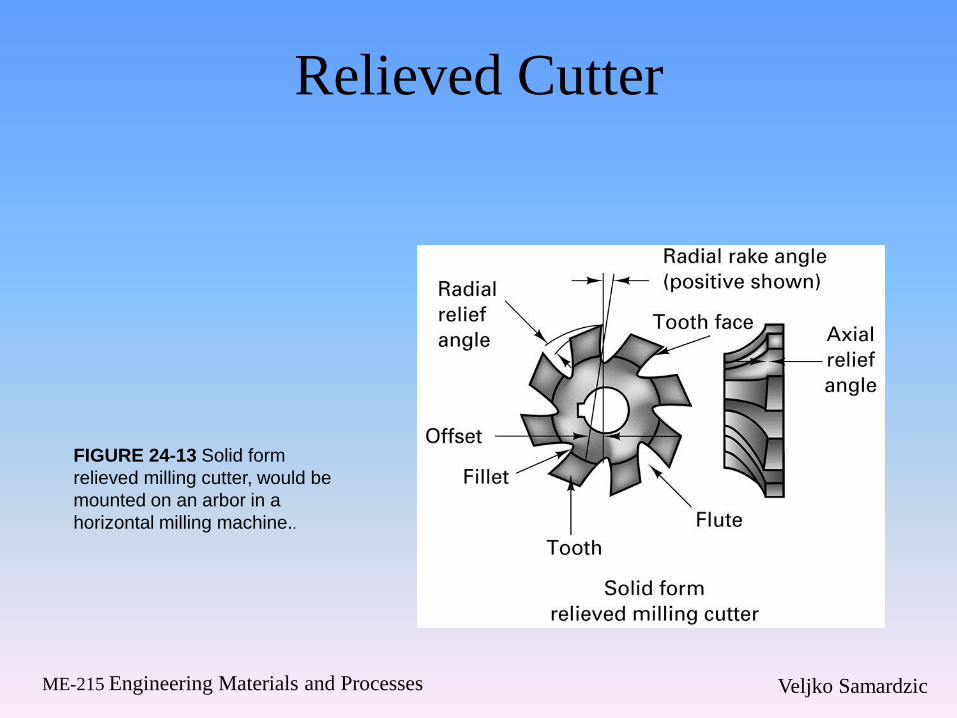
FIGURE 24-13 Solid form
relieved milling cutter, would be
mounted on an arbor in a
horizontal milling machine..

Veljko SamardzicME-215 Engineering Materials and Processes
24.4 Machines for Milling
• The four most common types of manually controlled milling machines are listed below in order of increasing power (and therefore metal removal capability):
– 1. Ram-type milling machines
– 2. Column-and-knee-type milling machines
• a. Horizontal spindle
• b. Vertical spindle
– 3. Fixed-bed-type milling machines
– 4. Planer-type milling machines
Veljko SamardzicME-215 Engineering Materials and Processes
Machines for Milling
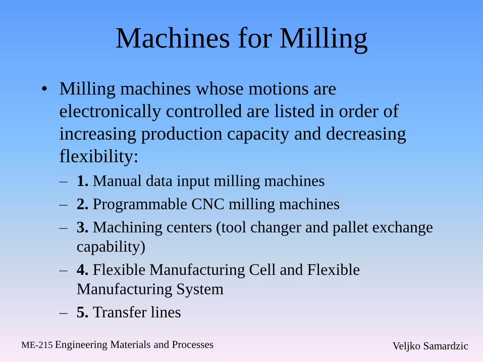
• Milling machines whose motions are
electronically controlled are listed in order of
increasing production capacity and decreasing
flexibility:
– 1. Manual data input milling machines
– 2. Programmable CNC milling machines
– 3. Machining centers (tool changer and pallet exchange
capability)
– 4. Flexible Manufacturing Cell and Flexible
Manufacturing System
– 5. Transfer lines

Veljko SamardzicME-215 Engineering Materials and Processes
Basic Mill Construction
• Most mills consist of column-and-knee designs
– The column is mounted on a base and the spindle
mounted on a knee extending from the column.
– The knee has vertical movement
– The material in mounted on a table with longitudinal
movement, and the table is mounted on a saddle with
transverse movement
• Most common of this type mill is the Ram mill
which has a motor and pulley system mounted on
the top of the column.
Veljko SamardzicME-215 Engineering Materials and Processes
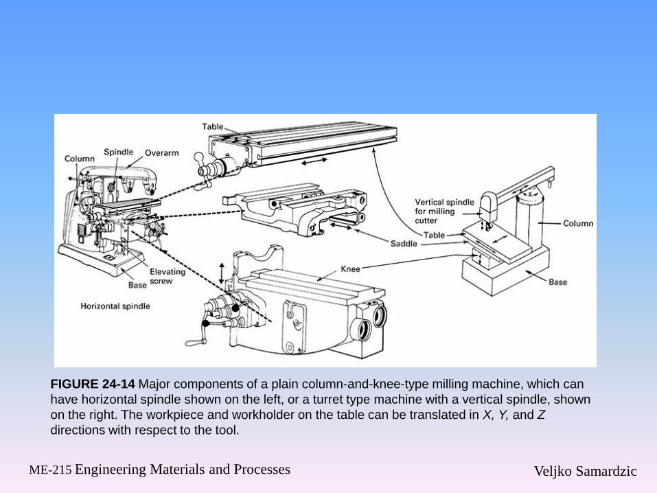
FIGURE 24-14 Major components of a plain column-and-knee-type milling machine, which can
have horizontal spindle shown on the left, or a turret type machine with a vertical spindle, shown
on the right. The workpiece and workholder on the table can be translated in X, Y, and Z
directions with respect to the tool.

Veljko SamardzicME-215 Engineering Materials and Processes
FIGURE 24-15 The ram-type knee-
and-column milling machine is one of
the most versatile and popular milling
machine tools ever designed.

Veljko SamardzicME-215 Engineering Materials and Processes
Bed Type Milling Machine
• Made for deep cuts and heavy material
removal, the bed only had horizontal
movement
• Once the bed is set up, the spindle height is
not changed during operation.
• These machines are very common due to
their ease of use.
Veljko SamardzicME-215 Engineering Materials and Processes
Bed Type Mill
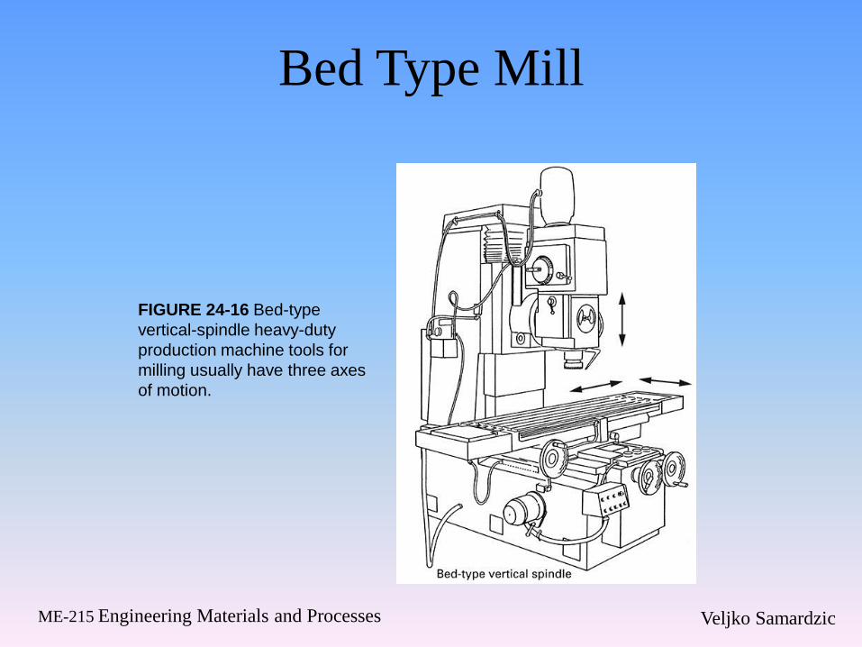
FIGURE 24-16 Bed-type
vertical-spindle heavy-duty
production machine tools for
milling usually have three axes
of motion.

Veljko SamardzicME-215 Engineering Materials and Processes
Planer Type Mill
• Planer type mills can have several heads to
remove large amounts of material while the
material is fed slowly into the machine.
• Systems are setup typically for single pass
operations.
• These are advantageous for large work
pieces requiring heavy material removal.

Veljko SamardzicME-215 Engineering Materials and Processes
FIGURE 24-17 Large
planertype milling
machine. Inset shows 90°
head being used.
(Courtesy of Cosa
Corporation.)

Veljko SamardzicME-215 Engineering Materials and Processes
Milling Machine Selection
• When purchasing or using a milling
machine, consider the following issues:
– 1. Spindle orientation and rpm
– 2. Machine capability (accuracy and precision)
– 3. Machine capacity (size of workpieces)
– 4. Horsepower available at spindle (usually
70% of machine horsepower)
– 5. Automatic tool changing


![ME -215 ENGINEERING MATERIALS AND PROCESES1]-Fall2017.pdfME-215 Engineering Materials and Processes Veljko Samardzic Important Dates in Technologies Development •B. Pascal- Mechanical](https://img.dokumen.tips/doc/110x75/5e6b7766c8afc96e9853cf1d/me-215-engineering-materials-and-proceses-1-me-215-engineering-materials-and.jpg)