Embed Size (px)
Citation preview

1
T.Y. Diploma : Sem. V [ME/PG/PT]
Advanced Manufacturing Processes Time: 3 Hrs.] Prelim Question Paper Solution [Marks : 100
Q.1(a) Attempt any THREE of the following: [12]Q.1(a) (i) State advantages & disadvantages of gear shaping process. [4](A) Advantages : Most Accurate gear tooth profiles are generated by this method. Rate of production of gear is higher than form cutter method. The same cutter of any given pitch can cut gears of any number of teeth of same pitch. Disadvantages : Not Suitable for internal gears Owing to the reciprocating action of cutter, there is no cutting on the return stroke in
gear shaper. Worms & Worm wheels cannot be generated on gear shaper. The rate of production is lower than gear hobbing process due to periodical indexing
hence More machining time. Q.1(a) (ii) Differentiate between EDM & W-EDM. [4](A)
EDM W-EDM (i) Complicated cutout cannot be easily
machined. Mirror shaped tool is used to produce desired shape.
Complicated cutout can be easily machined. Small diameter thin wire is used to cut desired profile
(ii) Electrode wear is more as compare to W-EDM
Electrode wear is negligible
(iii) Surface roughness is more Surface roughness of machined part is less
(iv) Surface micro structure may be distorted
No distortion in surface micro structure
(v) Tolerances are relatively open Geometrical & dimensional tolerances are tight.
Q.1(a) (iii) Differentiate between AJM and WJM. [4](A)
AJM WJM (i) Abrasive jet machining is process in
which working fluid is abrasives. Water jet machining water acts as a working fluid
(ii) Rate of material removal depends on abrasive size
Rate of material removal depends on water pressure jet.
(iii) Used for brittle and hard material Used for soft materials (iv) Used where mass production is required Not suitable for mass production (v) Capital cost is low Capital cost is high (vi) Process can be used for intricate shape
holes Used for cutting thin nonmetallic sheets
(vii) Suitable dust collection system is essential
WJM cleans work piece.

Vidyalankar : T.Y. Diploma AMP
2
Q.1(a) (v) Write any four advantages of non-traditional machining over conventional machining.
[4]
(A) (i) Applicable to all materials These methods are not affected by hardness, toughness and brittleness of work
materials.
(ii) Intricate shape machining It can produce complex-intricate shape on any workpiece material.
(iii) Extreme hard material machining Hard to machine materials like tungsten, uranium, tantalum can be machined.
(iv) No mechanical contact Material is removed without mechanical contact with the workpiece and tool.
Q.1(b) Attempt any ONE of the following: [6]Q.1(b) (i) With a neat labeled sketch, describe Laser Beam Machining process w.r.t. its
principle, applications and limitations. [6]
(A) Principle of laser machining : It works on the principle of conversion of electrical energy of flash lamp into heat
energy to emit the laser beam by pumping the energy. Laser beam is then focused by a lens to give high energy in the concentrated form and
helps to melt and vaporize the material of workpiece. As laser interacts with the material, the energy of photon is absorbed by the work
material leading to rapid rise in local temperature and results in melting and vaporization of the work material.
Working :
Laser beam machining utilizes the narrow beam of intense monochromatic light which melts and vaporize the material of the workpiece.
Fig. 1

Prelim Question Paper Solution
3
The setup for this process is shown in the figure 2. It mainly consists of: (i) Laser generation unit. (ii) Cooling arrangement. (iii) Collimating lens. (iv) Workpiece table
Application of Laser Beam Machining :
(i) Laser welding : It is useful for joining sheet metal or stock pieces of about 2.5 mm thick or less.
(ii) Laser drilling : It has ability to make small and very small holes of shallow depth. (iii) Laser cutting :
It used in cutting metals, plastics, ceramics, textile, cloths and even glass. It also used for cutting complex shapes.
Limitations of Laser Beam Machining : (i) It has very low material removal rate. (ii) It is not suitable for machining highly conductive and reflective materials like copper,
aluminium, and its alloys. (iii) Flash lamp has limited life. (iv) Machined holes may have taper from entry to exit. (v) High initial cost and maintenance cost. (vi) Overall efficiency is about 1015% (vii) Output energy of laser is difficult to control precisely.
Q.1(b) (ii) Sketch milling cutters for followings:
(1) Side milling (2) facing and (3) Plain milling [6]
(A) (1) Side milling (any one of below or similar)
(2) Facing (any one of below or similar)
(3) Plain (any one of below or similar)

Vidyalankar : T.Y. Diploma AMP
4
Q.2 Attempt any FOUR of the following : [16]Q.2(a) State any four needs for non-traditional machining process. [4](A) Four needs for non-traditional machining process (1) Replacement of existing manufacturing methods by more efficient & quicker methods. (2) Achievement of higher accuracies & quality of surface finish (3) Adaptability of cheaper materials in place of costlier one. (4) To do machining operations for “Hard to machine” materials like tungsten, uranium (5) To do machining operations on intricate & thin workpieces economically. (6) Development of new materials requires new methods Q.2(b) Explain Preventive Maintenance. [4](A) Preventive Maintenance
It is the planned maintenance of machine tools at regular intervals in order to prevent or minimize breakdown.
The primary goal of preventive maintenance is to prevent the failure of equipment before it actually occurs.
After preventive maintenance repairs, the equipment's health is restored back nearly to the equipment's original condition.
Preventive maintenance covers vast area like routine inspection, minor repairs, lubrication, cleaning, replacement of consumables like belts, gaskets etc. and overhauling and reconditioning.
In addition, workers can record equipment deterioration so they know to replace or repair worn parts before they cause system failure.
Maintenance work should be carried out by properly trained workers, to ensure rapid work at minimum cost.
Preventive maintenance is actually an investment to protect and prevent emergency and major breakdown from occurring.
The frequency of preventive maintenance is planned earlier and it is carried out at fixed time interval.
The interval is decided mainly keeping in view, the complexity of the machine tool and the amount of its usage.
The actual duration of preventive maintenance schedule is derived from manufacturer's recommendations, by past experience of similar machines or by monitoring the conditions.
The preventive maintenance schedule should be decided correctly otherwise preventive maintenance may lead to preventing production rather than to preventing breakdowns.
A tailor made programme for preventive maintenance is not practicable and the frequency should be improved over time.
Q.2(c) Sketch any two broaching tools. [4](A) Broaching tools: any two of the sketches or similar sketches Simple broach
Replaceable Shell type broach
Prelim Question Paper Solution
5
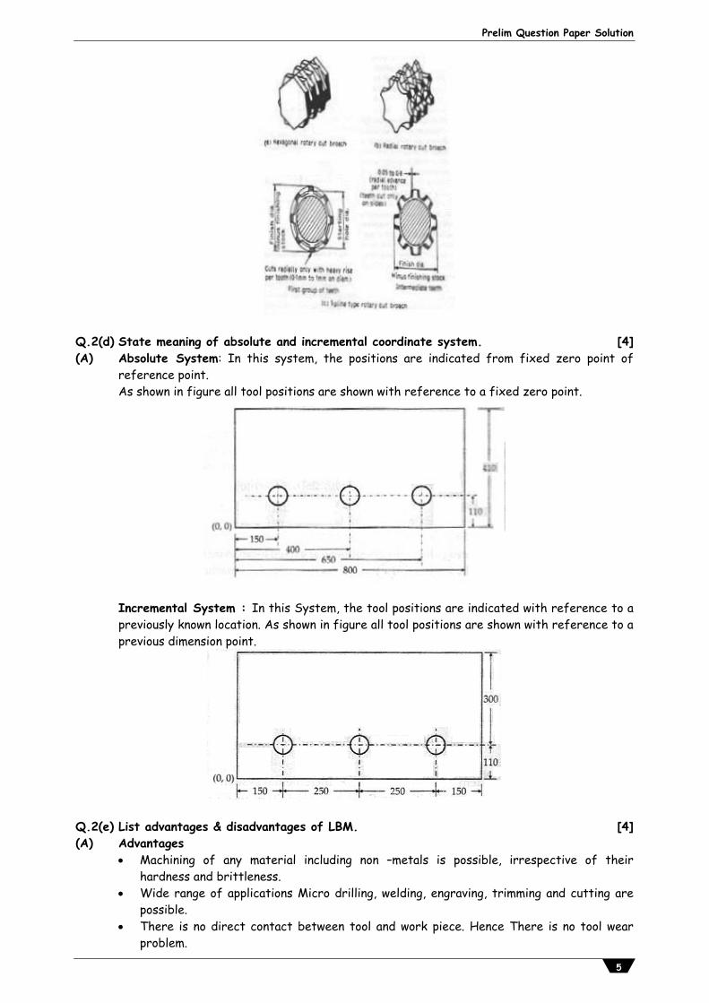
Q.2(d) State meaning of absolute and incremental coordinate system. [4](A) Absolute System: In this system, the positions are indicated from fixed zero point of
reference point. As shown in figure all tool positions are shown with reference to a fixed zero point.
Incremental System : In this System, the tool positions are indicated with reference to a previously known location. As shown in figure all tool positions are shown with reference to a previous dimension point.
Q.2(e) List advantages & disadvantages of LBM. [4](A) Advantages Machining of any material including non –metals is possible, irrespective of their
hardness and brittleness. Wide range of applications Micro drilling, welding, engraving, trimming and cutting are
possible. There is no direct contact between tool and work piece. Hence There is no tool wear
problem.

Vidyalankar : T.Y. Diploma AMP
6
The properties of machined materials are not affected by LBM. Easy control of beam configuration and size of exposed area. Extremely small holes can be machined. During LBM process no chip/burr are produced. In LBM laser can be sent and focussed at longer distance. Disadvantages LBM has very low material removal rate.Its overall efficiency is extremely low ( 10-
15%) - Process is limited to thin sheet plates Machined holes may became taper. are not round and straight. Life of the flash lamp is short. Effective safety procedures are required. High initial and maintenance Cost . Q.3 Attempt any TWO of the following : [16]Q.3(a) Describe construction and working of column and knee type milling machine with
neat sketch. [8]
(A)
This milling machine has two main structural elements. (1) A column (main frame) (2) A knee shaped projection table
Column contains the spindle and their drive mechanism and knee moves vertically on the column.
Six principle parts of this mechanisms are : 1) Base : The base on which the machine structure built. 2) Column : It contains the spindle and its driving mechanism. 3) Overam : It is mounted on column, it supports the other end of the arbor. 4) Knee : It is structural member attached to the column and which moves verticals. 5) Saddle : It is mounted on the knee and which moves horizontally. 6) Table : It is mounted on saddle which moves at right angles to the saddle. Work is
clamped on the table.
Working : Table of the machine has movement in three directions. (A) longitudinal (B) transverse (C) vertical Knee and column type milling machines are used for small and medium sized work in tool rooms and protype shops. This machines are made with both horizontal and vertical spindles They have manual or power control for all movements. The primary cutting motion is obtained by the milling cutter mounted on horizontal arbor with rotary motion and feed motion of worktable motion.

Prelim Question Paper Solution
7
Q.3(b) With suitable example, explain the steps for compound indexing. [8](A) Steps for Compound Indexing: (i) Factories the number of divisions required. (ii) Factories the standard number 40 (iii) Select for trial any two circles on the same plate and on its same side. Factories their
difference. (iv) Factories the number of holes of one circle. (v) Factories the number of holes of the other circle. After obtaining these factors place them as follows : Factors of divisions required X Factors of difference of hole circles Example: Compound Indexing for 51 divisions Required movement = 40/51 Let us try circles of 17 and 18 holes The first expression = 3X17X1 = 1/240 10X4X17X3X6 We get unity in numerator, so circles selected are correct. 240/17 – 240/18 Or 240/18 – 240/17 14 2/17 -13 6/18 Or 13 6/18 – 14 2/17 By taking out 14 as common, the above expression will be reduced as; 2/17 + 12/18 Or -12/18-2/17 Similar signs show that both the movements will be in the same direction. By adopting the
first result we get the required movement. Q.3(c) Write CNC programme for milling a component as shown in figure with end mill of
20 mm diameter, thickness of plate 10 mm, feed 90 mm/min, spindle rpm 450.Assume suitable data if necessary.
[8]
(A)
Pt X Y R Ps 10 0 P1 0 0 P2 105 0 P3 120 15 15 P4 120 65 P5 105 80 15 P6 40 80 P7 40 40 P8 0 40 P1 0 0

Vidyalankar : T.Y. Diploma AMP
8
N10 G90 G21 N20 T01 M06 N30 S1000 M03 N40 G00 X-10 Y0 N50 G00 Z5 M08 N60 G01 Z-10 N70 G01 G42 D01 X0 Y0 N80 G01 X105 Y0 N90 G03 X120 Y15 R15 OR G03 X120 Y15 I0 J15 ( If I & J method is used for arc) N100 G01 X120 Y65
N120 G03 X105 Y80 R15 OR G03 X105 Y80 I-15 J0 N130 G01 X40 Y80 N140 G01 X40 Y40 N150 G01 X0 Y40 N160 G01 X0 Y0 N170 G00 G40 Z5 N180 G91 G28 Z0 N190 M05 M09 N200 M30
Q.4(a) Attempt the THREE of the following: [12]Q.4(a) (i) Sketch milling cutters for following:
(1) Side milling (2) Facing (3) Plain milling [4]
(A) (1) Side milling
(2) Facing
(3) Plain milling

Prelim Question Paper Solution
9
Q.4(a) (ii) Sketch a planomiller with labels. [4](A) Planomiller
Q.4(a) (iii) Write short notes on Repair Complexity. [4](A) Repair Complexity
It indicates the complexity of a machine tool. (i.e. it tells about how complex a machine is to repair.)
Repair complexity cannot be measured by any absolute means, but can be decided from relative figures of similar machines.
It is a relative index to give a comparative idea of the complexity of a machine. It takes into account the mechanical gearings, hydraulics and pneumatic unit, guide
surfaces and other transmission units incorporated in the machine. Repair complexity is indicated by figures. Repair complexity plays a very important part in the machine tool maintenance. It helps in deciding the duration between the individual repair and in turn the repair
cycle. Also, the cost of repair, manpower required, spares required etc. depends upon the
complexity of the machine tool. For example, (i) Repair complexity for a centre lathe of small size is 5. (ii) Repair complexity for a medium duty milling machine is between 11 to 15. The Repair complexity for a machine changes with the change in specification. Its value increases with increase in capacity of the machine. Need of Repair Complexity The repair complexity concept is used to determine the following: (i) Number of maintenance personnel required. (ii) Quantity of spare parts required. (iii) List of the material required for the maintenance work. (iv) Estimate the annual repair cost of the machine tool. (v) Number of times the breakdown may occur. Importance of Repair Complexity (i) Tells about requirement of material for maintenance. (ii) Tells about requirement of time for maintenance. (iii) Tells to buy components required for maintenance. (iv) Tells about material, labour and overall cost.

Vidyalankar : T.Y. Diploma AMP
10
Q.4(a) (iv) Explain how grinding wheels are specified with suitable example. [4](A) Specification of Grinding Wheels with Suitable example: Grinding wheels are specified as: It consists of Six symbols representing properties of the grinding wheel. (1) Type of Abrasives (2) Grain size (3) grade (4) structure (5) Type of Bond (6) Manufacturers symbol for reference ( optional)
Apart from the above information , in order to specify grinding wheel completely, the size, ie Dia, and width or thickness and the dia of Bore are also required to be specify.
Example : 250 X 25 X 32 W A 46 L 4 V 17 Wheel Dia= 250mm Thickness of wheel= 25 mm Bore dia=32mm W = Manufacturers Prefix to Abrasive Here it is White A = Abrasive 46 = Grain Size L = Medium Grade 4= Dense Structure 17 = Bond type V = Vitrified Bond Q.4(b) Attempt any ONE of the following: [6]Q.4(b) (i) Compare capstan and turret lathe. [6](A)
Capstan lathe Turret lathe (i) It is a light duty machine It is a heavy duty machine (ii) The turret head is mounted on the
ram and the ram is mounted on the saddle.
The turret head is directly mounted on the saddle and the saddle slides over the bed ways
(iii) The saddle will not be moved during machining
The saddle is moved along with the turret head during machining
(iv) The lengthwise movement of turret is less
The lengthwise movement of turret is more
(v) Short work pieces only can be machined.
Long work pieces can be machined
(vi) It is easy to move the turret head as it slides over the ram
It is difficult to move the turret head along with saddle
(vii) The turret head cannot be moved crosswise
The turret head can be moved crosswise in some turret lathes
(viii) As the construction of lathe is not rigid, heavy cut cannot be given
As the construction of lathe is rigid, heavy cut can be given
(ix) It is used for machining work pieces up to 60mm diameter
It is used for machining work pieces up to 200mm diameter
(x) Collate is used to hold the work piece Jaw chuck is used to hold the work piece
Q.4(b) (ii) Explain Balancing of Grinding Wheel. [6](A) Balancing of Grinding Wheels
Introduction When a new grinding wheel is used, it should be first checked for proper balance. Most
manufactures balance their wheels before selling them.

Prelim Question Paper Solution
11
A wheel is said to be unbalanced when some portion of it is heavier, whereas the other is lighter. An unbalanced wheel will greatly affect the surface finish and accuracy of the work.
Effect of Unbalanced Wheel (1) At high rotational speeds, slight unbalance will produce vibrations that will cause
waviness in the work surface. (2) Unbalance may cause the wheel to break, with the chances of damage to the machine
and serious injury to the operator. (3) Excessive imbalance creates vibration which will damage the spindle bearings.
Wheels should be tested for balance occasionally and balanced if necessary.
Methods of Balancing of Wheel (1) Static balancing
In this method grinding wheel is taken off from the grinding machine and balanced with the help of balancing stand and arbor.
Wheel is balanced by using counterweights around the wheel flange at desired location. (2) Dynamic balancing In this method there is no need to remove grinding wheel from the machine and it
can be balance while wheel is running on the machine. New grinding machine has faciliting of automatic balance of grinding wheel. Procedure to Balance a Grinding Wheel (1) Mount the wheel and adapter on the surface grinder and true the wheel with
diamond dresser. (2) Remove the steel assembly and mount a special tapered balancing arbor in the hole
of the adapter. (3) Place the wheel and arbor on a balancing stand that has been levelled. (4) Allow the wheel to rotate until it stops and identify the heavy side and mark it with
chalk. (5) Rotate the wheel and stop it at three positions (90°, 180°, 270°) i.e. counter turn,
half turn, three quarter turn to check the balance. (6) Loosen the set screws in the wheel counter balances, in the grooved recess of the
flange and move the counter balances opposite the chalk mark. (7) Check the Wheel in the four positions mentioned in steps 4 and 5. (8) Move the counter balances around the groove and check for balance again. (9) Continue to move the balances away from the heavy side until the wheel remains
stationary at any position. (10) Tighten the counter balance in place.
Q.5 Attempt any FOUR of the following: [16]Q.5(a) List gear finishing processes. [4](A) (i) Gear shaving (ii) Gear grinding (iii) Gear lapping (iv) Gear honing (v) Gear burnishing

Vidyalankar : T.Y. Diploma AMP
12
Q.5(b) What is universal dividing head? State its function. [4](A) Universal Dividing Head This is a very important attachment used in a milling machine for gear cutting mechanism.
Dividing head, also known as indexing, is a mechanism employed for accurately spacing the teeth on the perimeter of the gear wheel blank to be machined.
The indexing may be classified as : (i) Rapid (ii) Plain (iii)Differential (iv) Compound and (v) Angular The universal dividing head is used for holding and indexing work through any desired arc of
rotation. The work may be mounted between centers or held in a chuck that is mounted in the spindle hole of the dividing head. The spindle can be tilted from about 5 degrees below horizontal to beyond the vertical position.
A special device known as raising block is used for locating the dividing head at 90 from its regular position on the milling machine's work table.
The dividing head is a rugged, accurate 40:1 worm gear reduction unit. The spindle of dividing head is rotated by one revolution by turning the input crank by 40 turns. An index plate, mounted breath the crank, contains a number of holes, arranged in concentric circles and equally spaced, with each circle having a different number of holes. A plunger pin on the crank handle can be adjusted to engage the holes of any circle. This permits the crank to be turned an accurate, fractional part of a complete circle. The number of turns of the index crank can be found for a given division on the work as under :
T = 40N
[This is true if the reduction ratio is 40:1]
where, T is the number of turns of the index crank and N is the number of division required on the work.
Q.5(c) Explain how grinding wheel is designated. [4](A) Grinding wheel designation: Grinding wheel is designated by six symbols representing following properties of grinding wheel. (i) Manufactures symbol (ii) Type of abrasive (iii) Grain size (iv) Grade (v) Structure (vi) Type of bond (vii) Manufacture symbol (optional) for reference
Eg.5I A 36 L 5 V 40 5I-manufacturers symbol indicating type of abrasive. � A-abrasive (aluminium oxide) 36-grain size (medium) L-grade (medium) 5-structure (dense) V-bond (vitrified) 40-manufacture symbol (optional)

Prelim Question Paper Solution
13
Q.5(d) Explain in short: (i) Burnishing (ii) Buffing [4](A) (i) Buffing: buffing is a polishing operation in which the work piece is brought in contact
with revolving cloth buffing wheel, that usually has been charged with the fine abrasive. The polishing action in buffing is very closely related to lapping.
(ii) Burnishing : Burnishing operation is the process of getting a smooth and shiny surface by contact and rubbing of the surface against the walls of hard tool. It is finishing and strengthening process. Burnishing is basically a cold surface plastic deformation process.
Q.5(e) With a neat sketch, describe working principle of honing process. State its two
applications. [4]
(A) Honing Process : Principle Honing is a wet cutting process which removes metal from the workpiece by means of
revolving tool that also reciprocate up and down usually inside the workpiece. Honing is usually adopted for internal cylindrical surfaces but by using special machines
it can be used for honing of external surfaces. Applications (1) Internal honing Engine cylinders, gun barrels, long tabular parts. (2) External surfaces Gear teeth, valve seating, races of roller and ball bearings, piston rods, piston pins,
spindles, shafts. Q.5(f) Write advantages & applications of CNC machine. [4](A) Advantages of CNC machine : (1) Reduced lead time (2) Elimination of operator error (3) Lower labour cost (4) High accuracy (5) Elimination of jigs and fixture (6) Flexibility (7) Reduced inspection (8) Less scrap Applications of CNC machine : (1) Electronics Parts Manufacturing (2) Engraving Machine Applications (3) Machining Composites (4) 5 Axis Machining (5) Dental Milling Applications (6) Micro Hole Drilling (7) Machining Aluminum (8) Machining Plastics Q.6 Attempt any FOUR of the following: [16]Q.6(a) Define boring, State types. [4](A) When internal surface of a hollow part is turned, that is, single point tool is used for
enlarging a hole, the operation is called as boring.

Vidyalankar : T.Y. Diploma AMP
14
Types of boring: Counter boring Counter sinking Spot facing
Q.6(b) Explain centreless grinding with sketch. [4](A) Centre-less grinding : This grinding machine is a production machine in which outside
diameter of the workpiece is ground. The workpiece is not held between centres but by a work support blade. It is rotated by means of a regulating wheel and ground by the grinding wheel. In through-feed centre-less grinding, the regulating wheel revolving at a much lower surface speed than grinding wheel controls the rotation and longitudinal motion of the workpiece. The regulating wheel is kept slightly inclined to the axis of the grinding wheel and the workpiece is fed longitudinally as shown in Fig.
Methods of Feed in the centre-less grinding are: (i) Through Feed (ii) In Feed (iii) End Feed (i) Through Feed : It is the simplest method and is applied only to the plain parallel parts
such as roller pins and straight long bars. (ii) In Feed : In the method there is no axial movement of the work-piece, the only
movement is the rotating movement. (iii) End Feed : The work-piece is fed as in case of in feed method and after certain portion
of length of work-piece has been ground, the axial movement takes place until whole length has been ground.
Q.6(c) State the significance of G01, G04, M06, M03 in part programming. [4](A) G01 Linear interpolation G04 Dwell M06 Tool change M03 Spindle start (clockwise) Q.6(d) State the types of maintenance of machine tools. [4](A) Types of maintenance of machine tools : Basically two types of maintenances Unplanned maintenance (i) Breakdown maintenance
Prelim Question Paper Solution
15
(ii) Corrective maintenance (iii) Opportunistic maintenance Planned maintenance (i) Preventive maintenance (ii) Predictive maintenance (iii) Corrective maintenance (iv) Routine maintenance (v) Design out maintenance (vi) Total productive maintenance Q.6(e) State advantages and disadvantages of broaching process. [4](A) Advantages :
(1) It is suitable for mass production as the rate of production is very high. (2) No special skill are required in this operation. (3) High accuracy and good surface finishing can be achieved by this operation. (4) In single pass roughing and finishing cut are possible. (5) Internal and external surface can be machined. (6) Variety of shapes can be reproduce. Disadvantages : (1) High tooling cost because broach is special multitooth cutter. The broach is usually
suitable for one type of job. (2) Large workpieces are difficult to mounts on the fixture and cannot broached. (3) The initial cost of the broach is very high as compared to other cutting tool. (4) Not suitable for small quantity and variety of sizes components due to high tooling cost. (5) Very light and delicate jobs cannot be broached easily. They may be broken distorted
due to high cutting process. Q.6(f) Compare pull broach and push broch. [4](A)
Pull broach Push broach (i) Broach is pulled through work piece Broach is pushed through work piece (ii) Broach is longer in length Broach is comparatively shorter in
length (iii) Length of surface to be machined is
long Length of surface to be machined is short
(iv) Number of teeth's are more Number of teeth's are less (v) Broach is in tension Broach is in compression

![Advanced Manufacturing Processes - diplomadiploma.vidyalankar.org › wp-content › uploads › AMP_Soln-1.pdf · Advanced Manufacturing Processes Time: 3 Hrs.] Prelim Question Paper](https://img.dokumen.tips/doc/110x75/5f0416417e708231d40c4138/advanced-manufacturing-processes-a-wp-content-a-uploads-a-ampsoln-1pdf.jpg)