Embed Size (px)
Citation preview

1 D2-1
Advanced inspection methods Advanced inspection methods –– A new approach to mills and A new approach to mills and
winderswinders
Shawn CrousShawn CrousAnglo AmericanAnglo American
Anglo Field ServicesAnglo Field ServicesSouth AfricaSouth Africa

2 D2-1
Order of PresentationOrder of Presentation
•• Mill Inspection historyMill Inspection history
•• Developing mill inspection packageDeveloping mill inspection package
•• Benefits of mill inspection packageBenefits of mill inspection package
•• Principle of Eddy Currents Principle of Eddy Currents
•• Eddy current usesEddy current uses
•• Eddy Current equipmentEddy Current equipment
•• Eddy Current signal Response Eddy Current signal Response
•• Eddy Current Gear InspectionEddy Current Gear Inspection
•• Case StudyCase Study
•• Winder Inspection historyWinder Inspection history
•• Developing winder inspection packageDeveloping winder inspection package
•• Benefits of winder inspection packageBenefits of winder inspection package
•• Principles Phased Array UltrasonicPrinciples Phased Array Ultrasonic
•• Phased Array ultrasonic equipmentPhased Array ultrasonic equipment
•• InspectionInspection
•• Case StudyCase Study
•• Winder Inspection PackageWinder Inspection Package
•• ConclusionConclusion
•• QuestionsQuestions

3 D2-1
Mill Inspection HistoryMill Inspection History
•• Magnetic Particle inspection of Magnetic Particle inspection of gear teethgear teeth
•• Timely operation due to the Timely operation due to the cleaning of the lubrication (+/cleaning of the lubrication (+/--12hours), using a solvent based 12hours), using a solvent based cleaner.cleaner.
•• Resulted in cleaning agents being Resulted in cleaning agents being trapped in the lubrication, breaking trapped in the lubrication, breaking down the viscosity.down the viscosity.
•• Only the gear inspection could be Only the gear inspection could be performed in this time period.performed in this time period.
•• Labour intensive.Labour intensive.

4 D2-1
Developing Mill Inspection PackageDeveloping Mill Inspection Package
•• By introducing an eddy current inspection technique to By introducing an eddy current inspection technique to inspect gear teeth, a number of other inspections can now be inspect gear teeth, a number of other inspections can now be performed in the same time frame:performed in the same time frame:–– Thermographic inspection of mill (Performed prior to shut)Thermographic inspection of mill (Performed prior to shut)
–– Drive train alignmentDrive train alignment
–– Gear mesh (Lead readings)Gear mesh (Lead readings)
–– Ultrasonic inspection of mill shell (WashUltrasonic inspection of mill shell (Wash--away)away)
–– Ultrasonic inspection of all boltingUltrasonic inspection of all bolting
–– Ultrasonic inspection of mill shell weldsUltrasonic inspection of mill shell welds
–– Magnetic particle inspection of pinion shaftsMagnetic particle inspection of pinion shafts
–– Ultrasonic inspection of Ultrasonic inspection of trunnionstrunnions (Wash(Wash--away)away)

5 D2-1
Benefits of mill inspection packageBenefits of mill inspection package
•• Benefits of using this advanced inspection method:Benefits of using this advanced inspection method:–– Reduction of labour Reduction of labour
–– No need to clean the gear teethNo need to clean the gear teeth
–– No more cleaning solvents trapped in the lubricationNo more cleaning solvents trapped in the lubrication
–– Reduction of inspection time (Mill gear teeth) Reduction of inspection time (Mill gear teeth)
–– Reduction in total inspection costReduction in total inspection cost
–– One report covering total condition of millOne report covering total condition of mill
–– One stop shop covering a multiple of inspectionsOne stop shop covering a multiple of inspections

6 D2-1
Principle of Eddy CurrentsPrinciple of Eddy Currents
•• Eddy Current Principle:Eddy Current Principle:–– Eddy current flow is induced in the test object. Changes in flowEddy current flow is induced in the test object. Changes in flow
caused by the variations in the specimen are reflected into coilcaused by the variations in the specimen are reflected into coils, s, these changes are analyzed by suitable instrumentation.these changes are analyzed by suitable instrumentation.
Conductivematerial
CoilCoil'smagnetic field
Eddy currents
Eddy current'smagnetic field

7 D2-1
Eddy Current usesEddy Current uses
•• Eddy currents can be used for a variety of inspections:Eddy currents can be used for a variety of inspections:–– Mill gear teethMill gear teeth
–– AluminiumAluminium componentscomponents
–– Vessel weldsVessel welds
–– Aircraft componentsAircraft components
–– Conductivity of materialConductivity of material
–– Coating thicknessesCoating thicknesses
–– Winder brake racesWinder brake races

8 D2-1
Eddy Current equipmentEddy Current equipment
•• EquipmentEquipment–– Differential probes manufactured to fit the gear profileDifferential probes manufactured to fit the gear profile
–– Eddy current instrumentEddy current instrument
–– Reference BlockReference Block
–– Frequency is between 8 and 100 kHzFrequency is between 8 and 100 kHz

9 D2-1
Eddy Current signal responseEddy Current signal response
Impedance Plain (DIFF)Impedance Plain (DIFF)Impedance Plain (DIFF)Impedance Plain (DIFF)
Longitudinal indicationLongitudinal indicationLocalised / circumferential Localised / circumferential indicationindication

10 D2-1
Eddy Current Gear InspectionEddy Current Gear Inspection
•• Eddy current inspection technique was developed as a Eddy current inspection technique was developed as a detection method to locate defects in gear teethdetection method to locate defects in gear teeth–– Pitting, Pitting, spallingspalling, cracking, etc., cracking, etc.
•• The defective areas are cleaned.The defective areas are cleaned.
•• The defects are then assessed using magnetic particle The defects are then assessed using magnetic particle inspection.inspection.
•• The size and orientation of the defects are then recorded The size and orientation of the defects are then recorded and reported.and reported.

11 D2-1
Case StudyCase Study
•• Signal response from a crack in a gear tooth.Signal response from a crack in a gear tooth.

12 D2-1
Mill Inspection PackageMill Inspection Package
•• ThermographicThermographic inspection of millinspection of mill–– BearingsBearings
–– ShellShell
–– gearsgears

13 D2-1
Mill Inspection Package (Continue)Mill Inspection Package (Continue)
•• Phased Array ultrasonic inspection of mill gear teethPhased Array ultrasonic inspection of mill gear teeth
14 D2-1
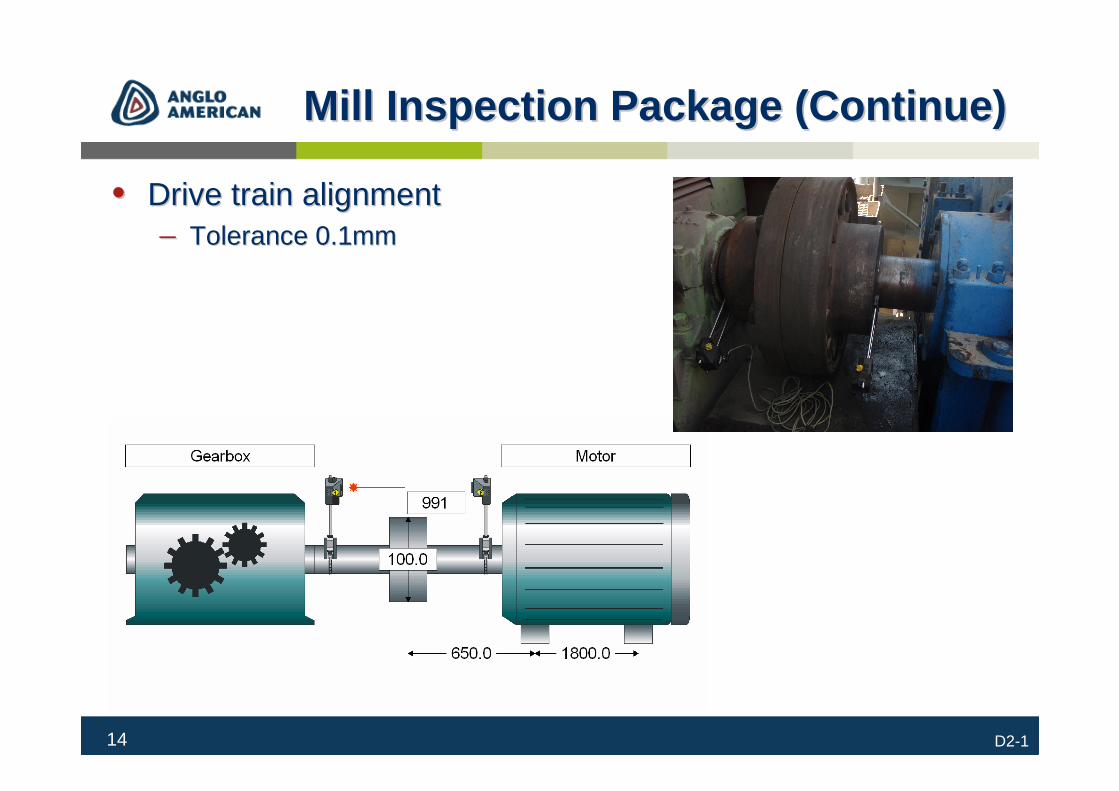
Mill Inspection Package (Continue)Mill Inspection Package (Continue)
•• Drive train alignmentDrive train alignment–– Tolerance 0.1mmTolerance 0.1mm

15 D2-1
Mill Inspection Package (Continue)Mill Inspection Package (Continue)
•• Gear meshGear mesh–– Lead readings to measureLead readings to measure
–– RootRoot
–– PressurePressure
–– BacklashBacklash

16 D2-1
Mill Inspection Package (Continue)Mill Inspection Package (Continue)
•• Ultrasonic inspection of mill shellUltrasonic inspection of mill shell–– BB--scanscan
–– WashWash--awayaway
17 D2-1
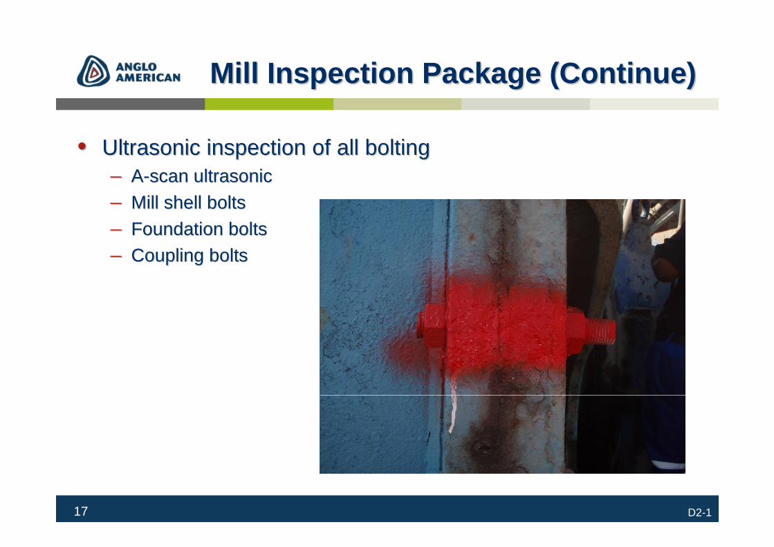
Mill Inspection Package (Continue)Mill Inspection Package (Continue)
•• Ultrasonic inspection of all boltingUltrasonic inspection of all bolting–– AA--scan ultrasonicscan ultrasonic
–– Mill shell boltsMill shell bolts
–– Foundation boltsFoundation bolts
–– Coupling boltsCoupling bolts

18 D2-1
Mill Inspection Package (Continue)Mill Inspection Package (Continue)
•• Ultrasonic inspection of shell weldsUltrasonic inspection of shell welds–– ToFDToFD
–– Phased ArrayPhased Array

19 D2-1
Mill Inspection Package (Continue)Mill Inspection Package (Continue)
•• Magnetic particle inspection of pinion shaftMagnetic particle inspection of pinion shaft–– Focussing on the keywayFocussing on the keyway
20 D2-1
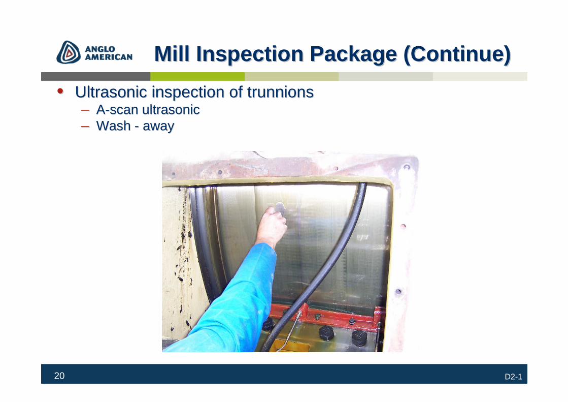
Mill Inspection Package (Continue)Mill Inspection Package (Continue)
•• Ultrasonic inspection of Ultrasonic inspection of trunnionstrunnions–– AA--scan ultrasonicscan ultrasonic–– Wash Wash -- awayaway

21 D2-1
Winder Inspection historyWinder Inspection history
•• Winder inspections are performed to assess the condition of Winder inspections are performed to assess the condition of its components for fitness for purpose:its components for fitness for purpose:–– Sheave wheel groove profileSheave wheel groove profile
–– Sheave wheel spindlesSheave wheel spindles
–– Sheave wheel to drum alignmentSheave wheel to drum alignment
–– Winder brake componentsWinder brake components
–– Winder gearbox teeth, hub and spokesWinder gearbox teeth, hub and spokes
–– Winder drum shaftWinder drum shaft
–– Winder drum alignmentWinder drum alignment
–– Winder drum boltsWinder drum bolts
–– Winder foundations bolts Winder foundations bolts
–– Winder brake racesWinder brake races

22 D2-1
Winder Inspection history (cont)Winder Inspection history (cont)
•• Most of these inspections were performed on separate days Most of these inspections were performed on separate days mostly on Sundaysmostly on Sundays..
•• Winder brake components:Winder brake components:–– Brake components are disassembled and cleanedBrake components are disassembled and cleaned
–– Magnetic particle inspectionMagnetic particle inspection
–– Ultrasonic inspectionUltrasonic inspection
–– Components are then assembledComponents are then assembled
•• Labour intensiveLabour intensive
•• Risk of components seizing when assembledRisk of components seizing when assembled

23 D2-1
Developing Winder PackageDeveloping Winder Package
•• By developing a Phased Array inspection technique to By developing a Phased Array inspection technique to inspect winder brake components (locating pins and tie rod inspect winder brake components (locating pins and tie rod threads), a number of inspections can now be performed in threads), a number of inspections can now be performed in the same time frame:the same time frame:

24 D2-1
Benefits of winder inspectionBenefits of winder inspection
•• Benefits of using this advanced inspection method:Benefits of using this advanced inspection method:–– Components do not have to be disassembled for inspectionComponents do not have to be disassembled for inspection
–– This inspection can be performed in a hoist examinationThis inspection can be performed in a hoist examination
–– Reduction of inspection time (Time it takes to disassemble and Reduction of inspection time (Time it takes to disassemble and assemble components)assemble components)
–– Reducing Sunday labour Reducing Sunday labour
–– Seizing of components is minimised Seizing of components is minimised
–– Other inspections can be performed in the same time frameOther inspections can be performed in the same time frame

25 D2-1
Principles of Phased Array ultrasonicPrinciples of Phased Array ultrasonic
•• The principles of Phased Array is based on the following:The principles of Phased Array is based on the following:–– Multiplexing of a large number of identical crystals as a singleMultiplexing of a large number of identical crystals as a single probe probe
–– Control of the focal depthControl of the focal depth
–– Control of the steering angleControl of the steering angle
–– Control of the beam focussingControl of the beam focussing
–– Program of the virtual probe aperture (VPA)Program of the virtual probe aperture (VPA)
–– Scan with a large number of AScan with a large number of A--scansscans
–– All scans can be encodedAll scans can be encoded
–– Can display CCan display C--scan, Bscan, B--scan, Sscan, S--scan and Ascan and A--scan views.scan views.

26 D2-1
Principles of Phased Array ultrasonic Principles of Phased Array ultrasonic (cont)(cont)
•• An array transducer is simply one that contains a number of An array transducer is simply one that contains a number of separate elements in a single housing, and phasing refers to separate elements in a single housing, and phasing refers to how those elements are sequentially pulsed how those elements are sequentially pulsed

27 D2-1
Phased Array ultrasonic equipmentPhased Array ultrasonic equipment
•• EquipmentEquipment–– Phased array InstrumentPhased array Instrument
–– Phased array transducer (multiPhased array transducer (multi--element)element)
–– Calibration BlockCalibration Block
–– Reference blocksReference blocks
–– CouplantCouplant

28 D2-1
PODPOD
•• 125mm diameter tie rod125mm diameter tie rod
•• Total number of flaws 13Total number of flaws 13
•• POD = Number of flaws detected/total number of flawsPOD = Number of flaws detected/total number of flaws
•• = 13/12= 13/12
•• = 0.923= 0.923
•• = 92.3%= 92.3%
•• A 2mm flaw went undetected as is was masked by a 4mm A 2mm flaw went undetected as is was masked by a 4mm flaw.flaw.

29 D2-1
InspectionInspection
•• Phased Array ultrasonics is used as a detection method:Phased Array ultrasonics is used as a detection method:–– To To loctelocte inin--service failure of winder brake components (service failure of winder brake components (tierodstierods and and
locating pins) while testing inlocating pins) while testing in--situ.situ.
–– Sizing of defects can be performed using normal ultrasonic Sizing of defects can be performed using normal ultrasonic principles. (6 or 20 db method)principles. (6 or 20 db method)
–– Results can be recorded. (Encoded)Results can be recorded. (Encoded)
–– Interpretation can be performed while scanning the components orInterpretation can be performed while scanning the components orthe stored data can be analysed after the inspection using tomovthe stored data can be analysed after the inspection using tomoview iew softwaresoftware

30 D2-1
Inspection (continue)Inspection (continue)
•• Phased inspection of the thread of a typical tie rodPhased inspection of the thread of a typical tie rod

31 D2-1
Case StudyCase Study
•• Two phased array images of a threaded tie rod.Two phased array images of a threaded tie rod.–– Image on the left shows no defectsImage on the left shows no defects
–– Image on the right shows defects at approximately 56 and 75 degrImage on the right shows defects at approximately 56 and 75 degrees.ees.

32 D2-1
Case Study (continue)Case Study (continue)
•• A 1mm deep crack at a depth of 200mm in a locating pin, A 1mm deep crack at a depth of 200mm in a locating pin,
detected with phased array at an angle of +/detected with phased array at an angle of +/--16 degrees.16 degrees.

33 D2-1
Case Study (continue)Case Study (continue)
•• A 1mm, 2mm, 3mm and 4mm flaws detected in the first four A 1mm, 2mm, 3mm and 4mm flaws detected in the first four threadsthreads
S-Scan image A-Scan image

34 D2-1
Winder Inspection PackageWinder Inspection Package
•• Time of Flight DiffractionTime of Flight Diffraction–– Drum shaft inspectionDrum shaft inspection

35 D2-1
Winder Inspection Package (cont)Winder Inspection Package (cont)
•• Winder drum alignmentWinder drum alignment–– Alignment of winder drumsAlignment of winder drums
–– Gives an indication of bearing conditionGives an indication of bearing condition

36 D2-1
Winder Inspection Package (cont)Winder Inspection Package (cont)
•• Sheave wheelsSheave wheels–– Sheave wheel spindlesSheave wheel spindles
–– Sheave wheel profilesSheave wheel profiles
–– Sheave to drum alignmentSheave to drum alignment
–– Magnetic particle inspection of sheave wheelsMagnetic particle inspection of sheave wheels

37 D2-1
Winder Inspection Package (cont)Winder Inspection Package (cont)
•• Winder boltsWinder bolts–– Ultrasonic inspectionUltrasonic inspection

38 D2-1
Winder Inspection Package (cont)Winder Inspection Package (cont)
•• Gearbox inspectionGearbox inspection–– Magnetic particle inspectionMagnetic particle inspection–– Eddy Current inspectionEddy Current inspection–– Gear teethGear teeth–– Gear spokes and hubGear spokes and hub–– Gear meshingGear meshing
39 D2-1
ConclusionConclusion
•• Using and developing the latest NDT technology can change Using and developing the latest NDT technology can change the way in which we currently perform inspections:the way in which we currently perform inspections:–– Making it simplerMaking it simpler
–– Better or comparable resultsBetter or comparable results
–– Saving on time (one stop shop)Saving on time (one stop shop)
–– Permanent records Permanent records

40 D2-1
Mill and Winder InspectionsMill and Winder Inspections
QUESTIONSQUESTIONS