Embed Size (px)
Citation preview
Fuel Cycle Research and Development Advanced Cladding Materials for Fuels Stuart A. Maloy M. Nastasi, A. Misra Los Alamos National Laboratory Peter Hosemann UC-Berkeley G.R. Odette UC-Santa Barbara D. Hoelzer Oak Ridge National Laboratory

Outline
Advanced Fuels Campaign in FCRD Materials Grand Challenges Clad Materials Issues Nanofeatures to improve radiation tolerance New research techniques at the nanoscale Summary
2

3
Advanced Fuels Campaign Mission & Objectives
Mission Develop and demonstrate fabrication processes and
in-pile performance of advanced fuels/targets (including the cladding) to support the different fuel cycle options defined in the NE roadmap.
Objectives Development of the fuels/targets that
– Increases the efficiency of nuclear energy production
– Maximize the utilization of natural resources (Uranium, Thorium)
– Minimizes generation of high-level nuclear waste (spent fuel)
– Minimize the risk of nuclear proliferation Grand Challenges
– Multi-fold increase in fuel burnup over the currently known technologies
– Multi-fold decrease in fabrication losses with highly efficient predictable and repeatable processes
– Develop and test advanced alloys for Next Generation LWR Fuels with Enhanced Performance and Safety and Reduced Waste Generation
Once- Through
Modified Open
Full Recycle
Advanced Fuels
High-burnup LWR fuels Ehhanced accident tolerant LWR fuels
- Deep-burn fuels or targets after limited used fuel treatment - High burnup fuels in new types of reactors
- Fuels and targets for continuous recycling of TRU in reactors (possibly in fast reactors)
4
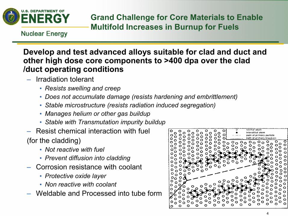
Grand Challenge for Core Materials to Enable Multifold Increases in Burnup for Fuels
Develop and test advanced alloys suitable for clad and duct and other high dose core components to >400 dpa over the clad /duct operating conditions – Irradiation tolerant
• Resists swelling and creep • Does not accumulate damage (resists hardening and embrittlement) • Stable microstructure (resists radiation induced segregation) • Manages helium or other gas buildup • Stable with Transmutation impurity buildup
– Resist chemical interaction with fuel (for the cladding)
• Not reactive with fuel • Prevent diffusion into cladding
– Corrosion resistance with coolant • Protective oxide layer • Non reactive with coolant
– Weldable and Processed into tube form
Challenges for Developing Core Materials For Next Generation LWR Fuels
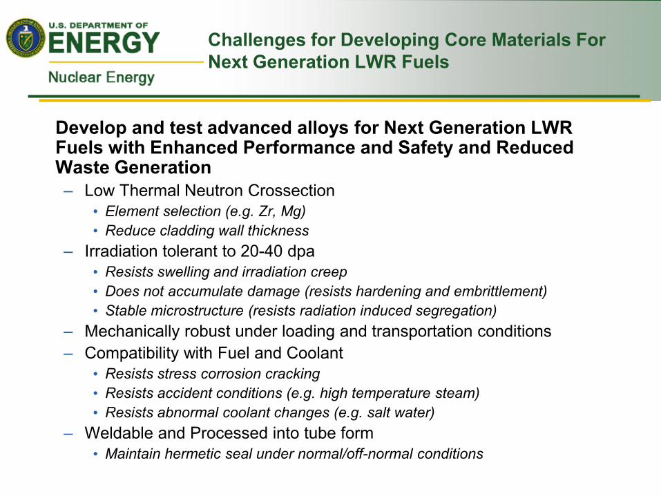
Develop and test advanced alloys for Next Generation LWR Fuels with Enhanced Performance and Safety and Reduced Waste Generation – Low Thermal Neutron Crossection
• Element selection (e.g. Zr, Mg) • Reduce cladding wall thickness
– Irradiation tolerant to 20-40 dpa • Resists swelling and irradiation creep • Does not accumulate damage (resists hardening and embrittlement) • Stable microstructure (resists radiation induced segregation)
– Mechanically robust under loading and transportation conditions – Compatibility with Fuel and Coolant
• Resists stress corrosion cracking • Resists accident conditions (e.g. high temperature steam) • Resists abnormal coolant changes (e.g. salt water)
– Weldable and Processed into tube form • Maintain hermetic seal under normal/off-normal conditions
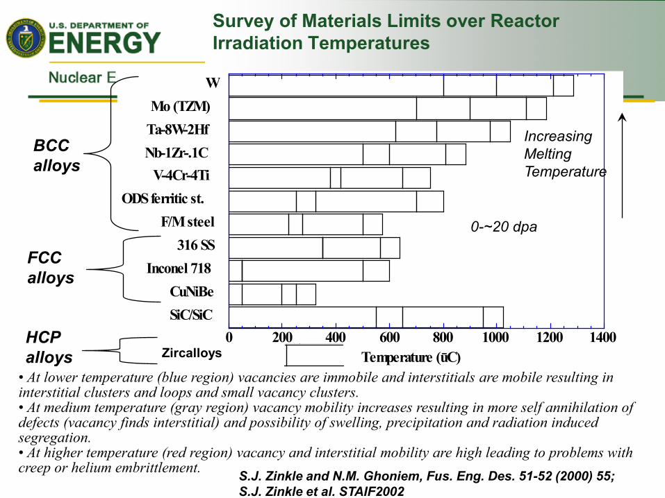
Survey of Materials Limits over Reactor Irradiation Temperatures
• At lower temperature (blue region) vacancies are immobile and interstitials are mobile resulting in interstitial clusters and loops and small vacancy clusters. • At medium temperature (gray region) vacancy mobility increases resulting in more self annihilation of defects (vacancy finds interstitial) and possibility of swelling, precipitation and radiation induced segregation. • At higher temperature (red region) vacancy and interstitial mobility are high leading to problems with creep or helium embrittlement. S.J. Zinkle and N.M. Ghoniem, Fus. Eng. Des. 51-52 (2000) 55;
S.J. Zinkle et al. STAIF2002
0 200 400 600 800 1000 1200 1400SiC/SiCCuNiBe
Inconel 718316 SS
F/M steelODS ferritic st.
V-4Cr-4TiNb-1Zr-.1CTa-8W-2HfMo (TZM)
W
BCC alloys
FCC alloys
Increasing Melting Temperature
0-~20 dpa
Zircalloys HCP alloys

Survey of Materials Limits over higher doses to 200 dpa
Nanofeatures to improve radiation tolerance- Can we vary alloy composition to improve radiation tolerance (e.g. add precipitates or solutes)? Can we reduce grain size for improved radiation tolerance? Aim to decrease low temperature embrittlement, reduce swelling or increase high temperature creep strength S.J. Zinkle and N.M. Ghoniem, Fus. Eng. Des. 51-52 (2000) 55;
S.J. Zinkle et al. STAIF2002
0 200 400 600 800 1000 1200 1400SiC/SiCCuNiBe
Inconel 718316 SS
F/M steelODS ferritic st.
V-4Cr-4TiNb-1Zr-.1CTa-8W-2HfMo (TZM)
W
BCC alloys
FCC alloys
Increasing Melting Temperature
100-200 dpa
Refractory alloys can experience embrittlement issues due to interstitial pickup (e.g. N, C or H), swelling and irradiation hardening.
FCC alloys run into swelling, segregation and precipitation leading to embrittlement
Zircalloys HCP alloys Hydrogen Embrittlement

Science-based vision to Core Materials Development
Ultra-high Burnup Fuels
Coa
ting
Line
rs
Adv
ance
d A
lloys
F/M
Ste
els
Adv
ance
d A
lloys
Cr Si Al
Increasing content
F/M
Ste
els
HT-
9
Adv
ance
d F/
M
Ste
els,
e.g
. NF6
16
OD
S S
teel
s
Adv
ance
d A
lloys
200 dpa 300 dpa 400 dpa
500 C 600 C 700 C
Reduced embrittlement, swelling, creep
Enhancements with Fabrication Complexity
Enhancements with Fabrication Complexity Enhancements with Fabrication Complexity
Different Reactor options to change
requirements LFR, GFR
FCCI
Radiation Temperature
Corrosion

Core Materials Research and Development
9
Develop the knowledge base up to 200 dpa- High Dose Core Materials Irradiation Data – ACO-3 Duct Testing
• Fracture Toughness testing • Charpy Testing • Tensile Testing • SANS measurements
– FFTF/MOTA Specimens and Testing Advanced Material Development
– Develop coatings/liners to Mitigate FCCI – Develop and test Advanced Cladding
materials • Improved Processing of Advanced ODS
Alloys

Strength can be Improved by 60% by adding nanofeatures in a Fe-Cr-Ni steel
M. Schober et al

• Any desired combination of powders: metals, alloys, and dispersoid, such as oxides, carbides, borides, etc.
A ferritic ODS alloy, 14YWT, is produced by Mechanical Alloying
The conventional approach is to ball mill Fe-alloy and Y2O3 powders together
HIP near net shape final product
Y2O3
(Fe-14Cr-3W-0.4Ti)
Zoz

Slide 12
Nanostructured materials such as ODS alloys show no or little radiation induced hardness change.
0.00
2.00
4.00
6.00
8.00
10.00
0
1
2
3
4
5
6
0 1 2 3 4 5 6 7 8
Nan
ohar
dnes
s [G
Pa]
Dose [dpa]
HT-9 Martensitic
HT-9 Ferritic
Dose
Dose [dpa] N
anoh
ardn
ess
[MP
a]
Depth [mm]
1mm
MA957
Room temperature irradiation (1.5dpa)
Depth [mm]
MA956

PNNL High Dose MA957 ODS Steel Examination
Analysis of MA957 1. Characterization of in-reactor creep response 2. TEM microstructural analysis to study creep
mechanisms 3. Tensile testing (and subsequent
microstructural examination) after irradiation to 100 dpa in FFTF.
4. APT analysis of oxide particles 5. 300+ dpa ion irradiations to study high dose
swelling response
2/28/2012
13
Machined tensile, ring pull, and TEM disk specimens.
Material for fabricating APT and TEM specimens
0.75 mm Completed 8 µm x 12 µm TEM foil
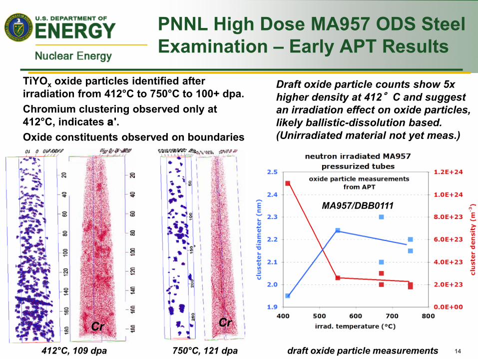
PNNL High Dose MA957 ODS Steel Examination – Early APT Results
14
0.75 mm
TiYOx oxide particles identified after irradiation from 412°C to 750°C to 100+ dpa.
Chromium clustering observed only at 412°C, indicates a'.
Oxide constituents observed on boundaries
412°C, 109 dpa
Cr
750°C, 121 dpa
Cr
draft oxide particle measurements
Draft oxide particle counts show 5x higher density at 412°C and suggest an irradiation effect on oxide particles, likely ballistic-dissolution based. (Unirradiated material not yet meas.)
MA957/DBB0111
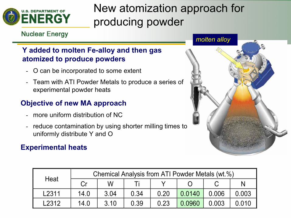
Y added to molten Fe-alloy and then gas atomized to produce powders
- O can be incorporated to some extent
- Team with ATI Powder Metals to produce a series of experimental powder heats
Objective of new MA approach - more uniform distribution of NC
- reduce contamination by using shorter milling times to uniformly distribute Y and O
Experimental heats
molten alloy
Heat Chemical Analysis from ATI Powder Metals (wt.%)
Cr W Ti Y O C N L2311 14.0 3.04 0.34 0.20 0.0140 0.006 0.003 L2312 14.0 3.10 0.39 0.23 0.0960 0.003 0.010
New atomization approach for producing powder
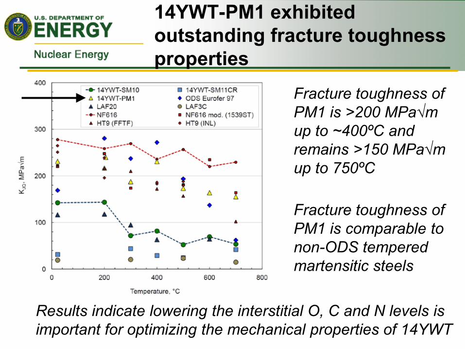
14YWT-PM1 exhibited outstanding fracture toughness properties
Fracture toughness of PM1 is >200 MPaup to ~400ºC and remains >150 MPaup to 750ºC
Fracture toughness of PM1 is comparable to non-ODS tempered martensitic steels
Results indicate lowering the interstitial O, C and N levels is important for optimizing the mechanical properties of 14YWT
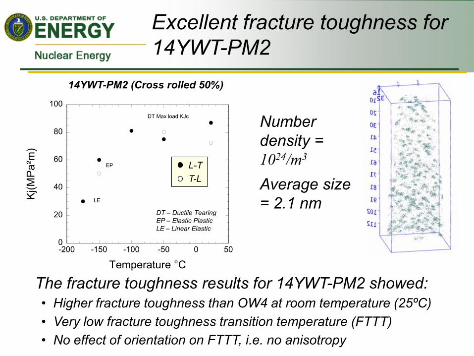
Excellent fracture toughness for 14YWT-PM2
0
20
40
60
80
100
-200 -150 -100 -50 0 50
PM2
Kj(M
Pa²
m)
Temperature °C
LE
EP
DT Max load KJc
14YWT-PM2 (Cross rolled 50%)
DT – Ductile Tearing EP – Elastic Plastic LE – Linear Elastic
The fracture toughness results for 14YWT-PM2 showed: • Higher fracture toughness than OW4 at room temperature (25ºC) • Very low fracture toughness transition temperature (FTTT) • No effect of orientation on FTTT, i.e. no anisotropy
L-T T-L
Number density = 1024/m3
Average size = 2.1 nm
an Office of Basic Energy Sciences Energy Frontier Research Center
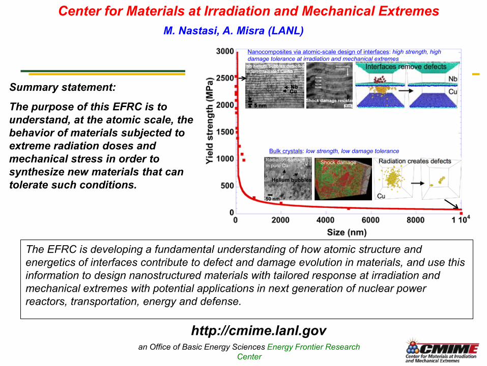
The EFRC is developing a fundamental understanding of how atomic structure and energetics of interfaces contribute to defect and damage evolution in materials, and use this information to design nanostructured materials with tailored response at irradiation and mechanical extremes with potential applications in next generation of nuclear power reactors, transportation, energy and defense.
50 nm
Helium bubbles
Radiation damagein pure Cu
50 nm
Helium bubbles
Radiation damagein pure Cu Shock damageShock damage
CuNb
5 nm
No helium bubbles detectedin ion-irradiated Cu-Nb
Shock damage resistance
CuNb
5 nm
No helium bubbles detectedin ion-irradiated Cu-Nb
CuNbCuNb
5 nm5 nm
No helium bubbles detectedin ion-irradiated Cu-Nb
Shock damage resistance
Bulk crystals: low strength, low damage tolerance
Nanocomposites via atomic-scale design of interfaces: high strength, high damage tolerance at irradiation and mechanical extremes
Center for Materials at Irradiation and Mechanical Extremes M. Nastasi, A. Misra (LANL)
http://cmime.lanl.gov
Summary statement:
The purpose of this EFRC is to understand, at the atomic scale, the behavior of materials subjected to extreme radiation doses and mechanical stress in order to synthesize new materials that can tolerate such conditions.
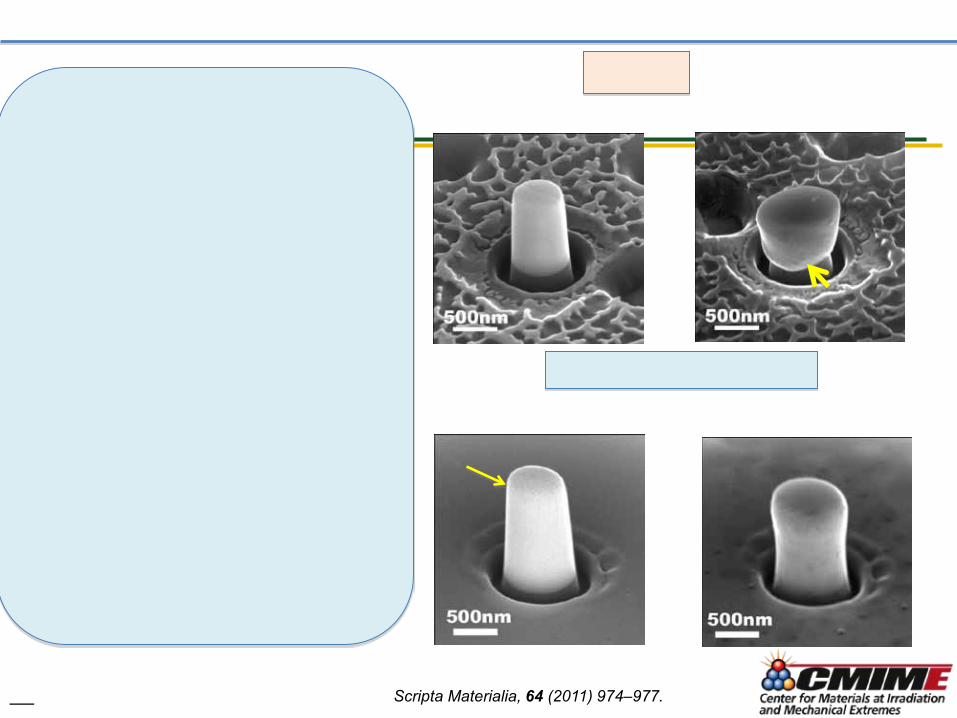
Scripta Materialia, 64 (2011) 974–977.
June 2, 2009 TFCIG Integration Meeting 20
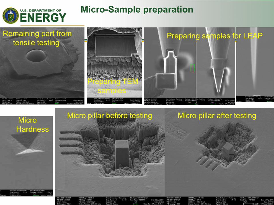
Micro-Sample preparation
Remaining part from tensile testing
Preparing TEM samples
Preparing samples for LEAP
Micro Hardness
Micro pillar before testing Micro pillar after testing

Example of Micro pillar results on MA957
Strain [-]
YS of macroscopic samples
Stre
ss [M
Pa]
0
500
1000
1500
2000
2500
0 0.05 0.1 0.15 0.2 0.25 0.3 0.35 0.4
ODS MA957 in the extrusion direction Compression force.
8 mm
8 mm
15mm
Post-test

Slide 22
Using ion beam irradiation to learn more on defect-dislocation interaction. First exp.: single crystal Cu
Before irradiation After irradiation

Slide 23
Nano pillar testing irradiated vs. unirradiated

Slide 24
Not irradiated Cu Irradiated Cu
Nano pillar testing irradiated vs. unirradiated

Summary
Nanoscale Applications in Core Materials for Nuclear applications – Radiation tolerant materials with nanofeatures
• ODS strengthened Steels • Maraging steels • Multilayers
– Nanoscale material preparation/testing • FIB- TEM foils • Micropillar testing • Nanopillars for in situ mechanical testing
New research underway to investigate the application of ODS alloys to LWR improved accident tolerant cladding development.
25