Embed Size (px)
Citation preview
1
Advanced Antenna for Digital Beamforming Synthetic Aperture Radar
ACT-10
Rafael Rincon, Jon Ranson, Temilola Fatoyinbo, Manohar Deshpande, Victor Marrero, Nelis du Toit, and Bobby Nanan. NASA/GSFC, Greenbelt, MD 20770
Martin Nowicki, and Matt Hanley NASA/WFF, Wallops, VA 23337
ESTO Forum, Oct 30, 2014
2
Objectives and Science Rational
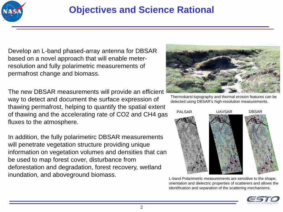
Develop an L-band phased-array antenna for DBSAR based on a novel approach that will enable meter-resolution and fully polarimetric measurements of permafrost change and biomass.
The new DBSAR measurements will provide an efficient way to detect and document the surface expression of thawing permafrost, helping to quantify the spatial extent of thawing and the accelerating rate of CO2 and CH4 gas fluxes to the atmosphere. In addition, the fully polarimetirc DBSAR measurements will penetrate vegetation structure providing unique information on vegetation volumes and densities that can be used to map forest cover, disturbance from deforestation and degradation, forest recovery, wetland inundation, and aboveground biomass.
Thermokarst topography and thermal erosion features can be detected using DBSAR’s high-resolution measurements.
L-band Polarimetric measurements are sensitive to the shape, orientation and dielectric properties of scatterers and allows the identification and separation of the scattering mechanisms.
PALSAR UAVSAR DBSAR
3
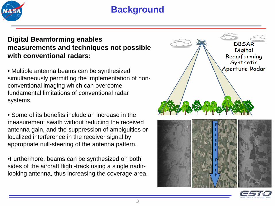
Digital Beamforming enables measurements and techniques not possible with conventional radars: • Multiple antenna beams can be synthesized simultaneously permitting the implementation of non-conventional imaging which can overcome fundamental limitations of conventional radar systems. • Some of its benefits include an increase in the measurement swath without reducing the received antenna gain, and the suppression of ambiguities or localized interference in the receiver signal by appropriate null-steering of the antenna pattern. •Furthermore, beams can be synthesized on both sides of the aircraft flight-track using a single nadir-looking antenna, thus increasing the coverage area.
Background
Flight Path
4
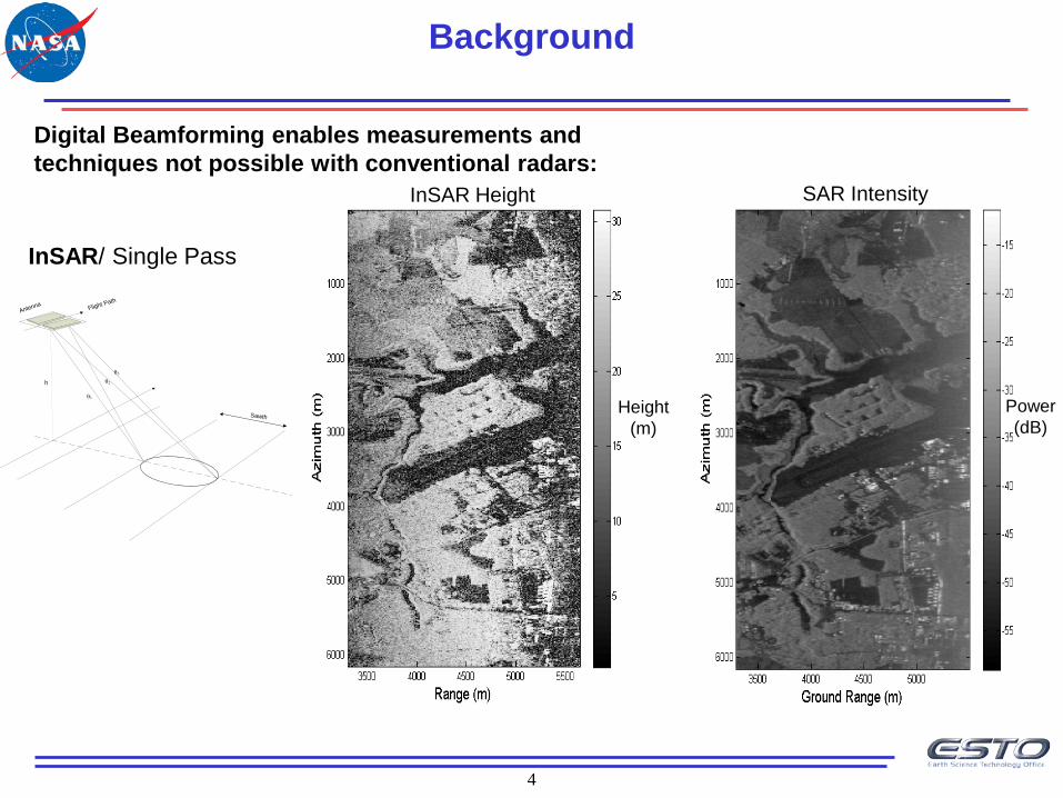
InSAR/ Single Pass
h
Flight Path
θ1
θ2
θ3
Sawth
Antenna
Height (m)
Power (dB)
Digital Beamforming enables measurements and techniques not possible with conventional radars:
Background
InSAR Height
SAR Intensity
5
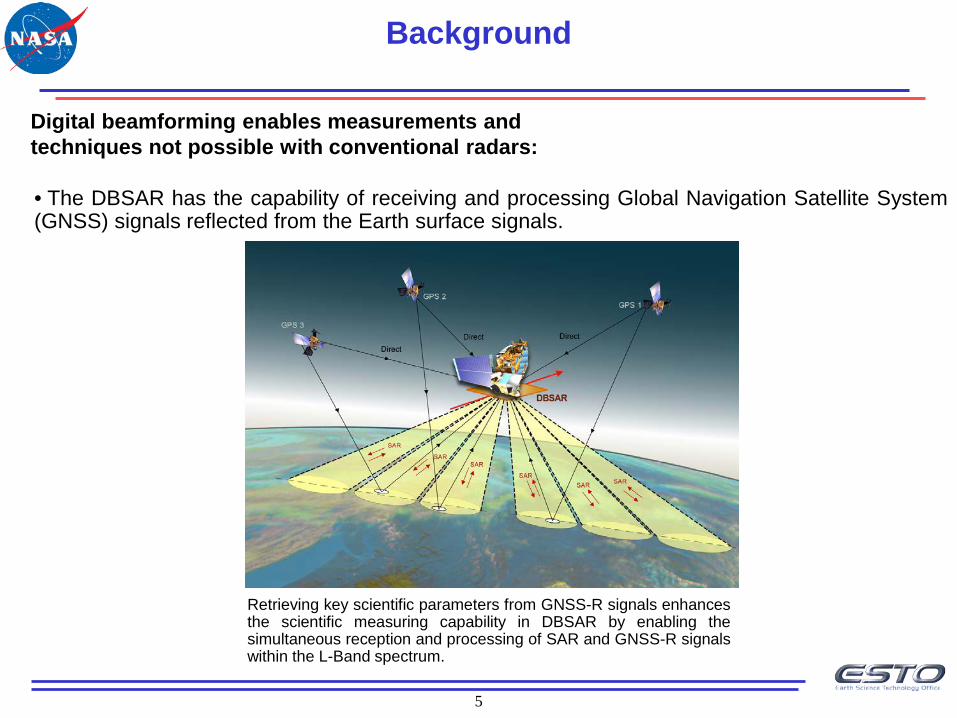
Digital beamforming enables measurements and techniques not possible with conventional radars:
Background
• The DBSAR has the capability of receiving and processing Global Navigation Satellite System (GNSS) signals reflected from the Earth surface signals.
Retrieving key scientific parameters from GNSS-R signals enhances the scientific measuring capability in DBSAR by enabling the simultaneous reception and processing of SAR and GNSS-R signals within the L-Band spectrum.
6
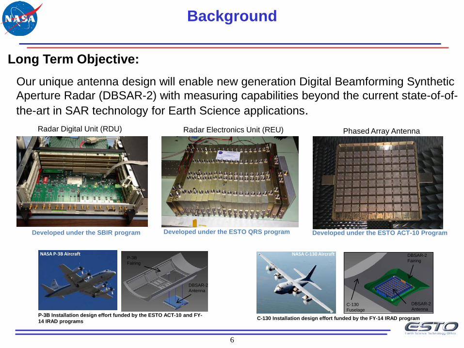
Long Term Objective:
Our unique antenna design will enable new generation Digital Beamforming Synthetic Aperture Radar (DBSAR-2) with measuring capabilities beyond the current state-of-of-the-art in SAR technology for Earth Science applications.
Developed under the ESTO QRS program Developed under the ESTO ACT-10 Program
Background
Radar Digital Unit (RDU)
Developed under the SBIR program
Radar Electronics Unit (REU) Phased Array Antenna
NASA C-130 Aircraft NASA P-3B Aircraft
P-3B Installation design effort funded by the ESTO ACT-10 and FY-14 IRAD programs C-130 Installation design effort funded by the FY-14 IRAD program
DBSAR-2 Antenna
DBSAR-2 Fairing
C-130 Fuselage
DBSAR-2 Antenna
P-3B Fairing
7
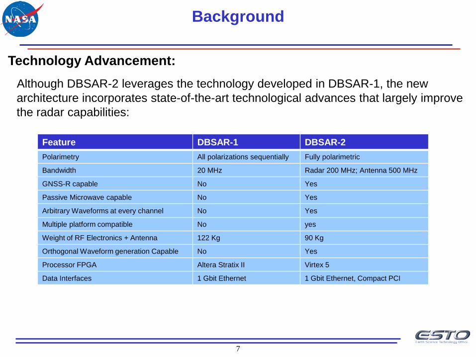
Technology Advancement:
Although DBSAR-2 leverages the technology developed in DBSAR-1, the new architecture incorporates state-of-the-art technological advances that largely improve the radar capabilities:
Background
Feature DBSAR-1 DBSAR-2 Polarimetry All polarizations sequentially Fully polarimetric
Bandwidth 20 MHz Radar 200 MHz; Antenna 500 MHz
GNSS-R capable No Yes
Passive Microwave capable No Yes
Arbitrary Waveforms at every channel No Yes
Multiple platform compatible No yes
Weight of RF Electronics + Antenna 122 Kg 90 Kg
Orthogonal Waveform generation Capable No Yes
Processor FPGA Altera Stratix II Virtex 5
Data Interfaces 1 Gbit Ethernet 1 Gbit Ethernet, Compact PCI
8
Antenna Requirements:
• Polarimetric and wideband phased array antenna
• Center Frequency: 1.26 GHz (L-band)
• Number of antenna elements : 80 (10 x 8, 64 active)
• Gain > 18 dB
• Bandwidth: 500 MHz (40 %)
• Cross - polarization discrimination (XPD): > 30 dB
• Port isolation: > 30 dB
• Array Scanning (SA): >= ± 35°
• Sidelobe level (one-way): < - 23 dB
• Weight: < 100 Kg
Background
9
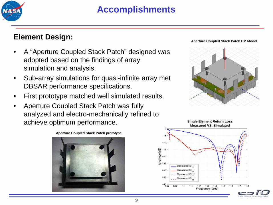
Element Design:
• A “Aperture Coupled Stack Patch” designed was adopted based on the findings of array simulation and analysis.
• Sub-array simulations for quasi-infinite array met DBSAR performance specifications.
• First prototype matched well simulated results. • Aperture Coupled Stack Patch was fully
analyzed and electro-mechanically refined to achieve optimum performance.
Accomplishments
Aperture Coupled Stack Patch EM Model
Aperture Coupled Stack Patch prototype
Single Element Return Loss Measured VS. Simulated
10
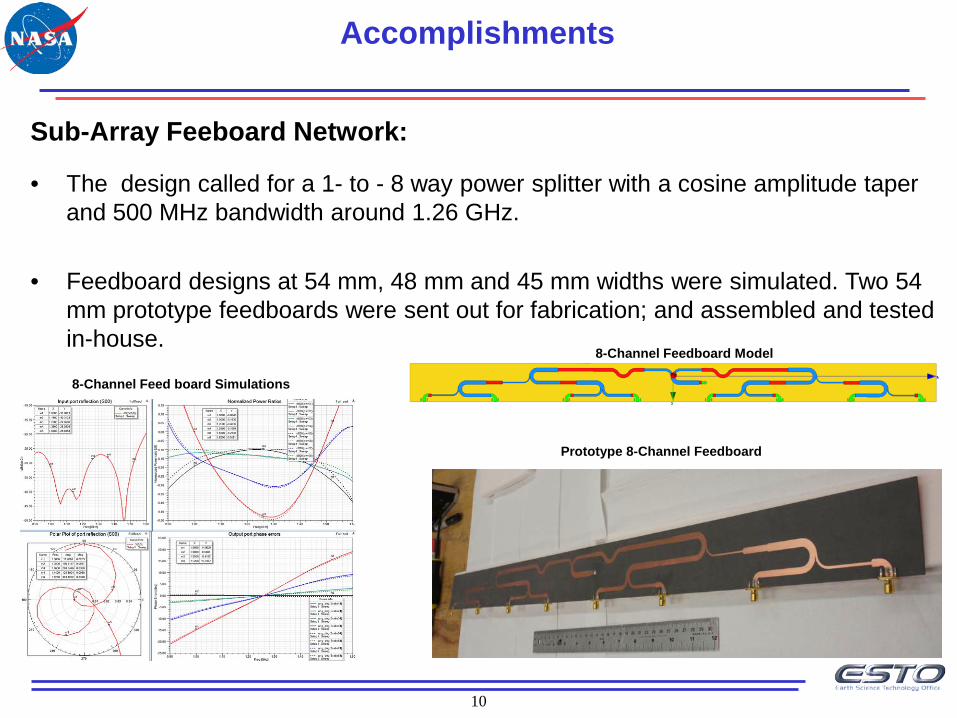
Sub-Array Feeboard Network:
• The design called for a 1- to - 8 way power splitter with a cosine amplitude taper and 500 MHz bandwidth around 1.26 GHz.
• Feedboard designs at 54 mm, 48 mm and 45 mm widths were simulated. Two 54
mm prototype feedboards were sent out for fabrication; and assembled and tested in-house.
8-Channel Feedboard Model
Prototype 8-Channel Feedboard
Accomplishments
8-Channel Feed board Simulations
11
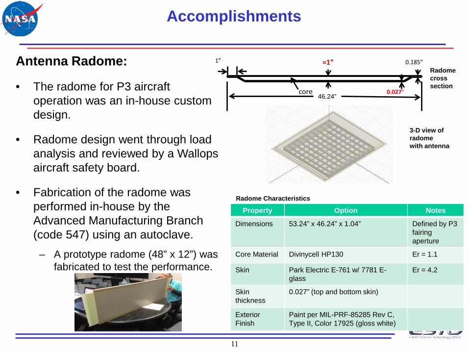
Antenna Radome:
• The radome for P3 aircraft operation was an in-house custom design.
• Radome design went through load analysis and reviewed by a Wallops aircraft safety board.
• Fabrication of the radome was performed in-house by the Advanced Manufacturing Branch (code 547) using an autoclave.
– A prototype radome (48” x 12”) was fabricated to test the performance.
Accomplishments
46.24” 0.027”
0.185” =1” 1”
core
Property Option Notes
Dimensions 53.24” x 46.24” x 1.04” Defined by P3 fairing aperture
Core Material Divinycell HP130 Er = 1.1
Skin Park Electric E-761 w/ 7781 E-glass
Er = 4.2
Skin thickness
0.027” (top and bottom skin)
Exterior Finish
Paint per MIL-PRF-85285 Rev C, Type II, Color 17925 (gloss white)
Radome cross section
3-D view of radome with antenna
Radome Characteristics
12
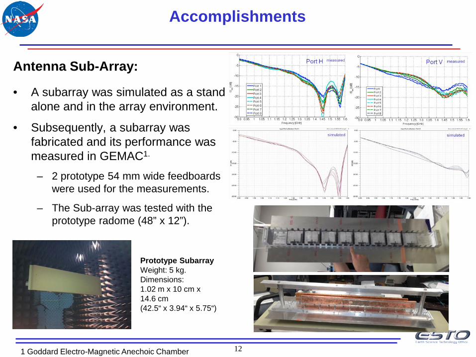
Antenna Sub-Array:
• A subarray was simulated as a stand alone and in the array environment.
• Subsequently, a subarray was fabricated and its performance was measured in GEMAC1.
– 2 prototype 54 mm wide feedboards were used for the measurements.
– The Sub-array was tested with the prototype radome (48” x 12”).
Prototype Subarray Weight: 5 kg. Dimensions: 1.02 m x 10 cm x 14.6 cm (42.5“ x 3.94“ x 5.75“)
1 Goddard Electro-Magnetic Anechoic Chamber
Accomplishments
13
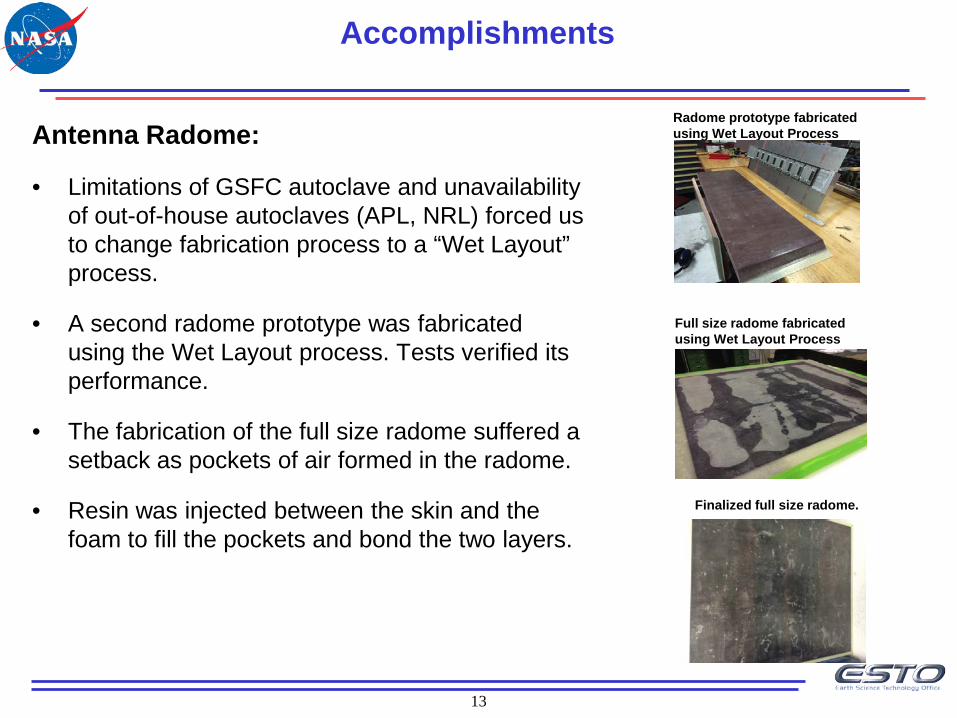
Antenna Radome:
• Limitations of GSFC autoclave and unavailability of out-of-house autoclaves (APL, NRL) forced us to change fabrication process to a “Wet Layout” process.
• A second radome prototype was fabricated using the Wet Layout process. Tests verified its performance.
• The fabrication of the full size radome suffered a setback as pockets of air formed in the radome.
• Resin was injected between the skin and the foam to fill the pockets and bond the two layers.
Accomplishments
Radome prototype fabricated using Wet Layout Process
Full size radome fabricated using Wet Layout Process
Finalized full size radome.
14
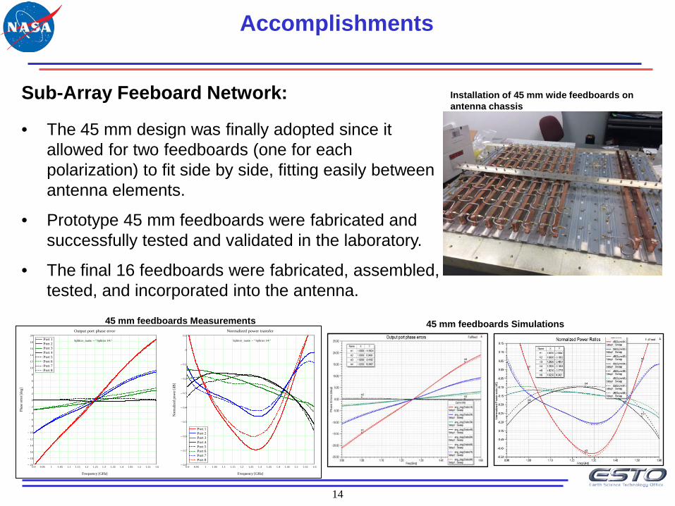
Sub-Array Feeboard Network:
• The 45 mm design was finally adopted since it allowed for two feedboards (one for each polarization) to fit side by side, fitting easily between antenna elements.
• Prototype 45 mm feedboards were fabricated and successfully tested and validated in the laboratory.
• The final 16 feedboards were fabricated, assembled, tested, and incorporated into the antenna.
Accomplishments
Installation of 45 mm wide feedboards on antenna chassis
0.9 0.95 1 1.05 1.1 1.15 1.2 1.25 1.3 1.35 1.4 1.45 1.5 1.55 1.620−
18−
16−
14−
12−
10−
8−
6−
4−
2−
0
2
4
6
8
10
12
14
16
18
20Port 1Port 2Port 3Port 4Port 5Port 6Port 7Port 8
Output port phase error
Frequency [GHz]
Phas
e erro
r [de
g]
0.9 0.95 1 1.05 1.1 1.15 1.2 1.25 1.3 1.35 1.4 1.45 1.5 1.55 1.60.8−
0.7−
0.6−
0.5−
0.4−
0.3−
0.2−
0.1−
0
0.1
Port 1Port 2Port 3Port 4Port 5Port 6Port 7Port 8
Normalized power transfer
Frequency [GHz]
Nor
mali
zed
pow
er [d
B]
Splitter_name "Splitter 14\"= Splitter_name "Splitter 14\"=
45 mm feedboards Measurements 45 mm feedboards Simulations
15
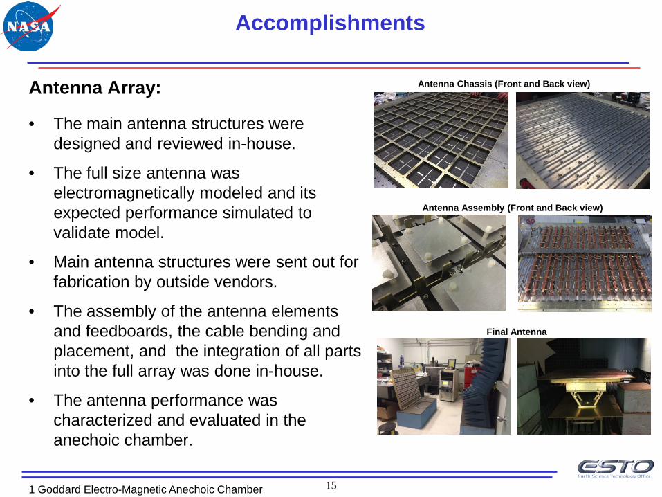
Antenna Array:
• The main antenna structures were designed and reviewed in-house.
• The full size antenna was electromagnetically modeled and its expected performance simulated to validate model.
• Main antenna structures were sent out for fabrication by outside vendors.
• The assembly of the antenna elements and feedboards, the cable bending and placement, and the integration of all parts into the full array was done in-house.
• The antenna performance was characterized and evaluated in the anechoic chamber.
1 Goddard Electro-Magnetic Anechoic Chamber
Accomplishments
Antenna Chassis (Front and Back view)
Antenna Assembly (Front and Back view)
Final Antenna
16
Technology Development Results
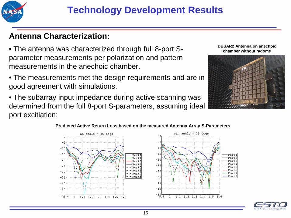
DBSAR2 Antenna on anechoic chamber without radome
Predicted Active Return Loss based on the measured Antenna Array S-Parameters
Antenna Characterization: • The antenna was characterized through full 8-port S-parameter measurements per polarization and pattern measurements in the anechoic chamber. • The measurements met the design requirements and are in good agreement with simulations. • The subarray input impedance during active scanning was determined from the full 8-port S-parameters, assuming ideal port excitiation:
17
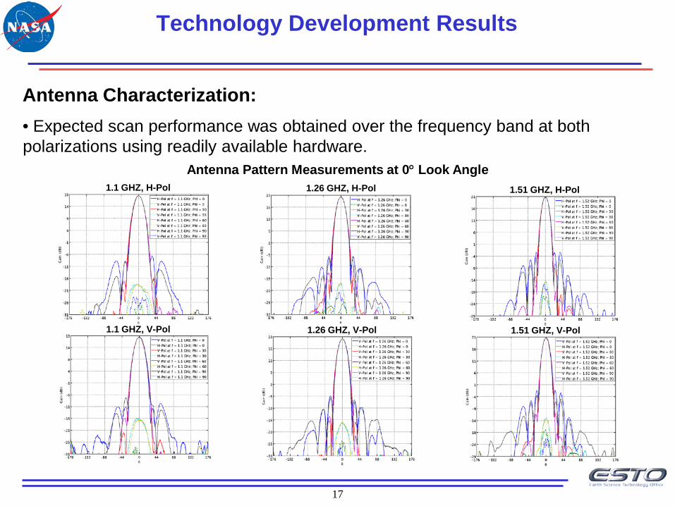
Antenna Characterization: • Expected scan performance was obtained over the frequency band at both polarizations using readily available hardware.
Technology Development Results
Antenna Pattern Measurements at 0° Look Angle 1.1 GHZ, H-Pol
1.1 GHZ, V-Pol
1.26 GHZ, H-Pol
1.26 GHZ, V-Pol
1.51 GHZ, H-Pol
1.51 GHZ, V-Pol
18
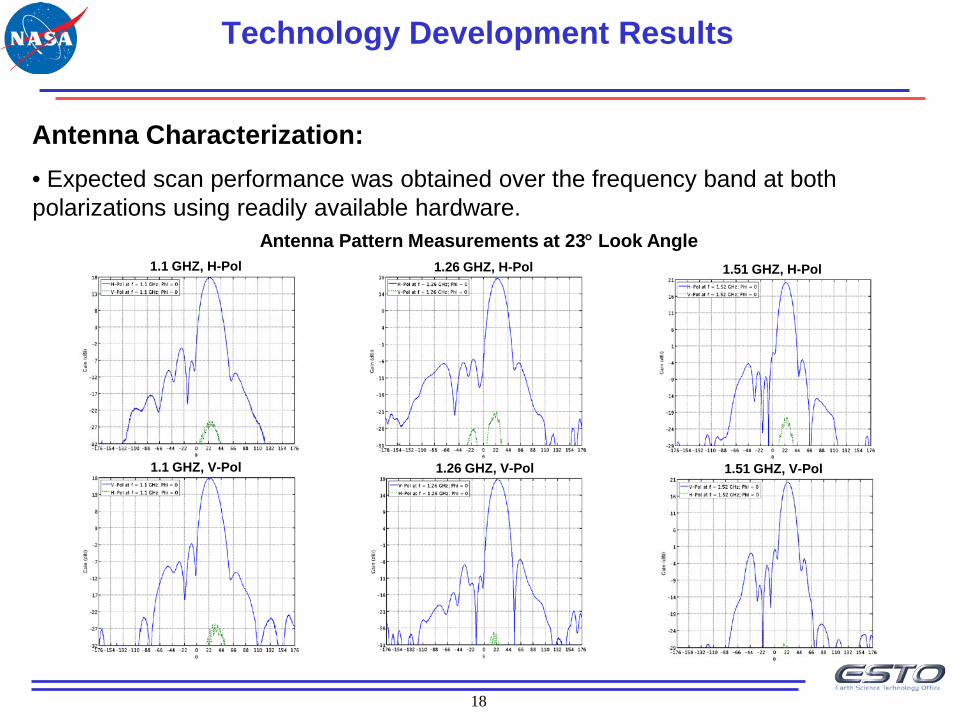
Antenna Characterization: • Expected scan performance was obtained over the frequency band at both polarizations using readily available hardware.
Technology Development Results
Antenna Pattern Measurements at 23° Look Angle 1.1 GHZ, H-Pol
1.1 GHZ, V-Pol
1.26 GHZ, H-Pol
1.26 GHZ, V-Pol
1.51 GHZ, H-Pol
1.51 GHZ, V-Pol
19
Technology Development Results
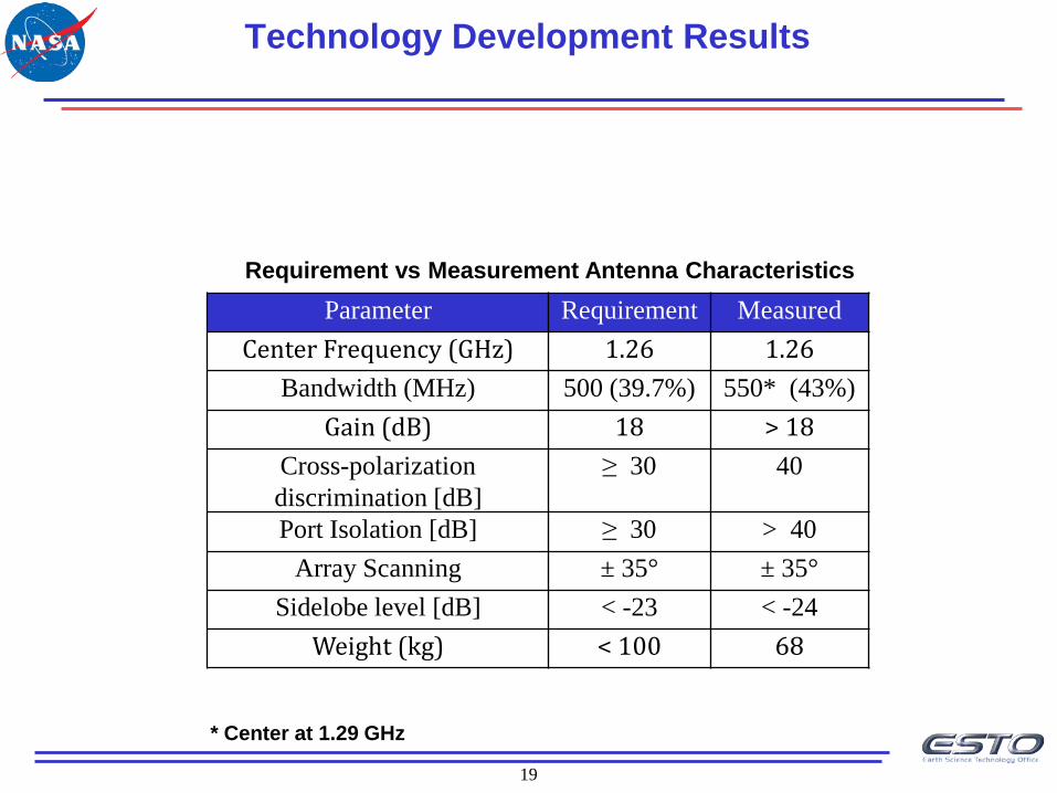
Requirement vs Measurement Antenna Characteristics Parameter Requirement Measured
Center Frequency (GHz) 1.26 1.26 Bandwidth (MHz) 500 (39.7%) 550* (43%)
Gain (dB) 18 > 18 Cross-polarization discrimination [dB]
≥ 30 40
Port Isolation [dB] ≥ 30 > 40 Array Scanning ± 35° ± 35°
Sidelobe level [dB] < -23 < -24 Weight (kg) < 100 68
* Center at 1.29 GHz
20
Conclusions and Future Plans
• This project successfully developed a state-of-the-art antenna for the Next Generation Digital Beamforming SAR (DBSAR-2).
• The measured performance of the antenna exceeded the design requirements.
• To bring the technology to a TRL 6, we plan to fly DBSAR-2 on board the C-130 aircraft in the Summer of 2015.
• The DBSAR-2 Instrument subsystems are currently being calibrated and integrated in the laboratory in preparation for the upcoming flight campaign.
• We also plan to seek additional funding for instrument maturation, airborne flight tests, and flight campaigns through the Airborne Instrument Transition Technology (AITT), and Earth Venture (EV) opportunities.