Embed Size (px)
Citation preview

Advanced and parallel architectures Cognome Nome
Prof. A. Massini _________________________________
Exam – July 13, 2015
Part A
Exercise 1a (2 points)
Exercise 1b (4 points) Exercise 2 (3 points)
Exercise 3 (3 points)
Exercise 4a (3 points)
Exercise 4b (3 points) Exercise 4c (3 points)
Question 1 (5 points)
Question 2 (5 points)
Total (31 points)

Exercise 1a (2 points) – Number representation Given the values A= 00 10 01 10 01 11 and B= 11 10 00 11 00 01 in the signed RB (Redundant Binary) representation, convert A and B in decimal. Exercise 1b (4 points) – Number representation Describe the procedure to compute the opposite of a number in the RB (Redundant Binary). Show step by step how to apply the procedure to compute -B (given in Exercise 1a) .
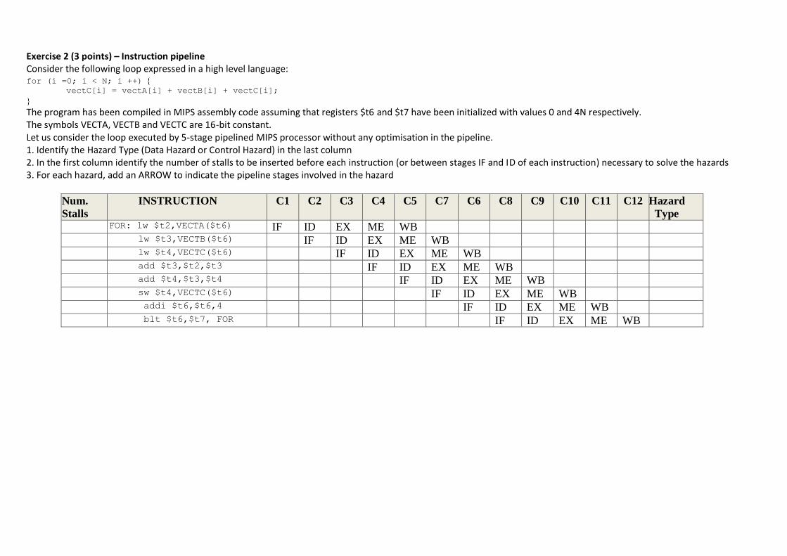
Exercise 2 (3 points) – Instruction pipeline Consider the following loop expressed in a high level language: for (i =0; i < N; i ++)
vectC[i] = vectA[i] + vectB[i] + vectC[i];
The program has been compiled in MIPS assembly code assuming that registers $t6 and $t7 have been initialized with values 0 and 4N respectively. The symbols VECTA, VECTB and VECTC are 16-bit constant. Let us consider the loop executed by 5-stage pipelined MIPS processor without any optimisation in the pipeline. 1. Identify the Hazard Type (Data Hazard or Control Hazard) in the last column 2. In the first column identify the number of stalls to be inserted before each instruction (or between stages IF and ID of each instruction) necessary to solve the hazards 3. For each hazard, add an ARROW to indicate the pipeline stages involved in the hazard
Num.
Stalls
INSTRUCTION C1 C2 C3 C4 C5 C7 C6 C8 C9 C10 C11 C12 Hazard
Type
FOR: FOR: lw $t2,VECTA($t6) IF ID EX ME WB
lw $t3,VECTB($t6) IF ID EX ME WB
lw $t4,VECTC($t6) IF ID EX ME WB
add $t3,$t2,$t3 IF ID EX ME WB
add $t4,$t3,$t4 IF ID EX ME WB
sw $t4,VECTC($t6) IF ID EX ME WB
addi $t6,$t6,4 IF ID EX ME WB
blt $t6,$t7, FOR IF ID EX ME WB

Exercise 3 (3 points) – Pipelined operations Show the scheme and the execution of the pipelined addition: 13+10, and verify the results.

Exercise 4a (3 points) – Interconnection networks
Complete the scheme of the Butterfly and Baseline networks of size N=8.
Write the permutation obtained by swapping the most MSB and the LSB in the binary representation of inputs (in the case of 3 bit):
67452301P
Show if the Butterfly and Baseline Networks can realize this permutation, by showing the switch setting, using the self-routing.
Exercise 4a (3 points) – Interconnection networks
Complete the scheme of the Butterfly and Baseline networks of size N=8.
Write the permutation obtained by rotating right the binary representation of inputs (in the case of 3 bit):
67452301P
Show if the Butterfly and Baseline Networks can realize this permutation, by showing the switch setting, using the self-routing.

Exercise 4c (3 points) – Interconnection networks
Design a Clos network of size 50 x50, using modules 10x10 in both cases , strictly non blocking and rearrangeable.

Question 1 (5 points) Question 2 (5 points)
Explain what are blocking and rearrangeable interconnection networks, also giving examples.
_____________________________________________________
_____________________________________________________
_____________________________________________________
_____________________________________________________
_____________________________________________________
_____________________________________________________
_____________________________________________________
_____________________________________________________
_____________________________________________________
_____________________________________________________
_____________________________________________________
_____________________________________________________
_____________________________________________________
_____________________________________________________
_____________________________________________________
_____________________________________________________
_____________________________________________________
_____________________________________________________
_____________________________________________________
_____________________________________________________
_____________________________________________________
_______________________________________________
Describe the instruction pipeline.
_____________________________________________________
_____________________________________________________
_____________________________________________________
_____________________________________________________
_____________________________________________________
_____________________________________________________
_____________________________________________________
_____________________________________________________
_____________________________________________________
_____________________________________________________
_____________________________________________________
_____________________________________________________
_____________________________________________________
_____________________________________________________
_____________________________________________________
_____________________________________________________
_____________________________________________________
_____________________________________________________
_____________________________________________________
_____________________________________________________
_____________________________________________________
_______________________________________________


Advanced and parallel architectures Cognome Nome
Prof. A. Massini _________________________________
Exam – July 13, 2015
Part B
Exercise 1a (2 points) Exercise 1b (3 points)
Exercise 1c (3 points)
Exercise 2 (3points)
Exercise 3 (4 points) Exercise 4a (2 points)
Exercise 4b (3 points)
Exercise 4c (3 points)
Question 1 (5 points)
Question 2 (5 points)
Total (33 points)

Exercise 1a (2 points) – GPU We want to use each thread to calculate four (adjacent) elements of a vector addition. Assume that a variable i should be the index for the first element to be processed by a thread. What would be the expression for mapping the thread/block indices to data index?
Explain.

Exercise 1b (3 points) – GPU Consider a tridimensional matrix of size 1200x1200x1200. You would like to assign one thread to each matrix element. You would like your thread blocks to be cubic. How would you select the grid dimensions and block dimensions of your kernel to minimize the number of idle threads on a device having compute capability 3.0?
Exercise 1c (3 points) – GPU Consider the tridimensional matrix of size 1200x1200x1200, as in Exercise 1b. You would like to assign one thread to each matrix element. How would you select the grid dimensions and block dimensions of your kernel if you want tridimensional blocks of maximum size (and you do not need blocks are
cubic), on a device having compute capability 3.0?
Technical specifications Compute capability (version)
1.0 1.1 1.2 1.3 2.x 3.0 3.5 3.7 5.0 5.2
Maximum dimensionality of grid of thread blocks 2 3
Maximum x-dimension of a grid of thread blocks 65535 231-1
Maximum y-, or z-dimension of a grid of thread blocks 65535
Maximum dimensionality of thread block 3
Maximum x- or y-dimension of a block 512 1024
Maximum z-dimension of a block 64
Maximum number of threads per block 512 1024
Warp size 32
Maximum number of resident blocks per multiprocessor 8 16 32
Maximum number of resident warps per multiprocessor 24 32 48 64
Maximum number of resident threads per multiprocessor 768 1024 1536 2048
Technical specifications 1.0 1.1 1.2 1.3 2.x 3.0 3.5 3.7 5.0 5.2
Compute capability (version)

Exercise 2 (3 points) – Loop dependences In the following loop, find all the true dependences, output dependences and antidependences, the loop carried dependences. Eliminate the output dependences and antidependences by renaming. for (i=1; i<=n; i++)
{
A[i]=B[i]+2; \*S1*\
B[i]=C[i]*2; \*S2*\
D[i]=E[i]+C[i]; \*S3*\
E[i]=B[i]+E[i-1]; \*S4*\
B[i]=A[i]/2; \*S5*\
}

Exercise 3 (4 points) - Cache coherence
Consider a multicore multiprocessor implemented as a symmetric shared-memory architecture, as illustrated in the figure.
Each processor has a single, private cache with coherence maintained using the snooping coherence protocol. Each cache is direct-mapped, with four blocks each holding two words. The coherence states are denoted M, S, and I (Modified, Shared, and Invalid).
Each part of this exercise specifies a sequence of one or more CPU operations of the form: P#: <op> <address> [<value>] where P# designates the CPU (e.g., P0), <op> is the CPU operation (e.g., read or write), <address> denotes the memory address, and <value> indicates the new word to be assigned on a write operation. For each part of this exercise, assume the initial cache and memory state as illustrated in the figure and treat actions as applied one after another starting from the initial state shown in the figure. Show in the table for the results: - miss/hit - the coherence state before the action - the CPU processor Pi and cache block Bj - the changed state (i.e., coherence state, tags, and data) of the caches and memory after the given action. Specify the value returned by a read operation.
P0
Coherency state
Address tag
Data
B0 S 100 00 08
B1 M 120 00 32
B2 S 124 00 12
B3 S 112 00 16
P1
Coherency state
Address tag
Data
B0 S 100 00 08
B1 I 120 00 28
B2 S 124 00 12
B3 S 112 00 16
P3
Coherency state
Address tag
Data
B0 S 100 00 08
B1 I 120 00 28
B2 I 108 00 32
B3 S 112 00 16
On chip interconnect (with coherency manager)
Memory
Address Data
… … …
100 00 08
104 00 04
108 00 08
112 00 16
116 00 20
120 00 28
124 00 12
… … …
P2
Coherency state
Address tag
Data
B0 M 116 00 32
B1 I 120 00 28
B2 M 108 00 36
B3 S 112 00 16

a) P2: write 100 24
hit/miss state before
Pi.Bj (state, tag, datawords)
b) P0: read 100
hit/miss state before
Pi.Bj (state, tag, datawords)
c) P1: write124 20
hit/miss state before
Pi.Bj (state, tag, datawords)
d) P2: write 124 32
hit/miss state before
Pi.Bj (state, tag, datawords)
Comments

Exercise 4a (2 points) - Performance Consider 3 processors P1, P2 and P3 with clock rates and CPI given below, are running the same program:
Which processor will have the best performance?
clock rate CPI
P1 2.5 GHz 1.4
P2 1.7 GHz 1.2
P3 2.7 GHz 2.1

Exercise 4b (3 points) – Amdhal Law Three enhancements with the following speedups are proposed for a new architecture: Speedup1 = 15 Speedup2 = 25 Speedup3 = 30 Assume for some benchmark, the fraction of use is 60% for each of enhancements 1, 25% for enhancement 2 and 20% for enhancement 3. What enhancement should be implemented to maximize performance?

Exercise 4c (3 points) – Amdhal Law Assume that we are considering enhancing a machine by adding vector hardware to it. When a computation is run in vector mode on the vector hardware, it is 15 times faster than the normal mode of execution. We call the percentage of time that could be spent using vector mode the percentage of vectorization.
Suppose you have measured the percentage of vectorization of the program to be 60%. The hardware design group estimates it can speed up the vector hardware even more with significant additional investment. You wonder whether the compiler crew could increase the percentage of vectorization, instead. What percentage of vectorization would the compiler team need to achieve in order to equal an addition 2× speedup in the vector unit (beyond the initial 15x)?

Question 1 (5 points) Question 2 (5 points)
Describe the memory hierarchy in a GPU.
_____________________________________________________
_____________________________________________________
_____________________________________________________
_____________________________________________________
_____________________________________________________
_____________________________________________________
_____________________________________________________
_____________________________________________________
_____________________________________________________
_____________________________________________________
_____________________________________________________
_____________________________________________________
_____________________________________________________
_____________________________________________________
_____________________________________________________
_____________________________________________________
_____________________________________________________
_____________________________________________________
_____________________________________________________
_____________________________________________________
_____________________________________________________
_______________________________________________
Describe the Data Flow Machine.
_____________________________________________________
_____________________________________________________
_____________________________________________________
_____________________________________________________
_____________________________________________________
_____________________________________________________
_____________________________________________________
_____________________________________________________
_____________________________________________________
_____________________________________________________
_____________________________________________________
_____________________________________________________
_____________________________________________________
_____________________________________________________
_____________________________________________________
_____________________________________________________
_____________________________________________________
_____________________________________________________
_____________________________________________________
_____________________________________________________
_____________________________________________________
_______________________________________________