Embed Size (px)
Citation preview

Advanced 3D printed heat pipes for space applications
Heat Exchanger Action Group (HEXAG) meeting 22 May 2013
Masoud Ameli PhD student at
Department of Engineering and Environment

Contents
Introduction - Brief Overview of Thermacore
- What is Heat Pipe?
- Aluminium AGHP’s
Ammonia heat pipes and AGHPs - Space applications
- AGHPs shortcomings
Additive layer manufactured – 3D printed heat pipes
- Selective Laser Melting (SLM) technique
- SLM porous and solid structures
- SLM heat pipe
- Test results
- Other applications
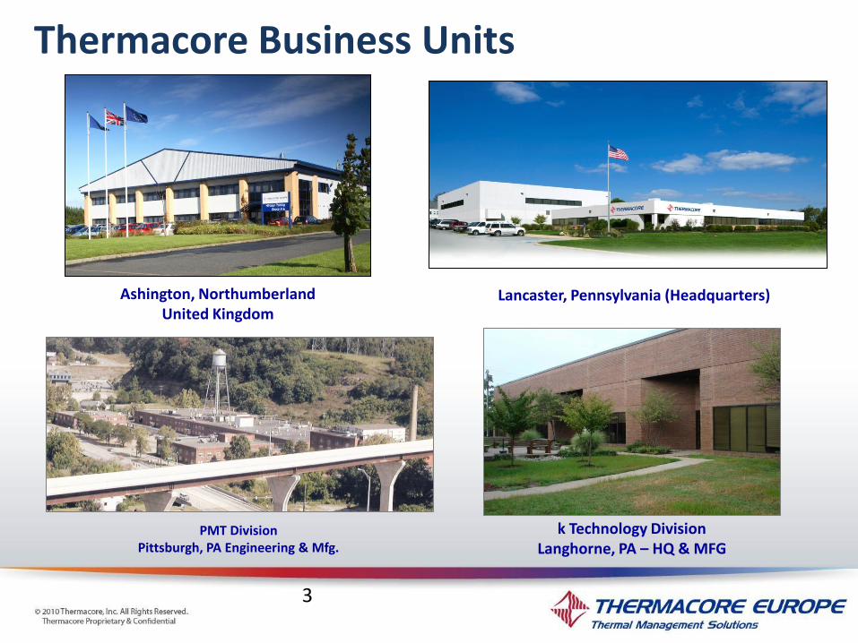
Thermacore Business Units
3
Ashington, Northumberland United Kingdom
Lancaster, Pennsylvania (Headquarters)
k Technology Division Langhorne, PA – HQ & MFG
PMT Division Pittsburgh, PA Engineering & Mfg.
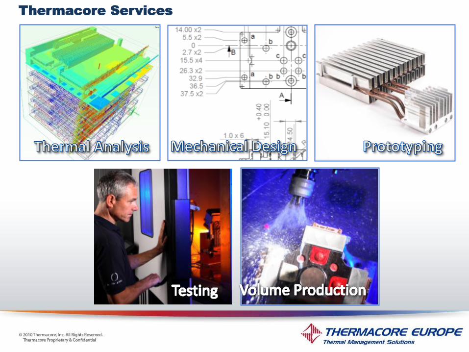
Thermacore Services
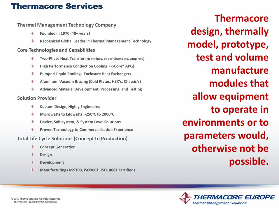
Thermal Management Technology Company
Founded in 1970 (40+ years)
Recognized Global Leader in Thermal Management Technology
Core Technologies and Capabilities
Two-Phase Heat Transfer (Heat Pipes, Vapor Chambers, Loop HPs)
High Performance Conduction Cooling (k-Core® APG)
Pumped Liquid Cooling, Enclosure Heat Exchangers
Aluminum Vacuum Brazing (Cold Plates, HEX’s, Chassis’s)
Advanced Material Development, Processing, and Testing
Solution Provider
Custom Design, Highly Engineered
Microwatts to kilowatts, -250°C to 2000°C
Device, Sub-system, & System Level Solutions
Proven Technology to Commercialisation Experience
Total Life Cycle Solutions (Concept to Production)
Concept Generation
Design
Development
Manufacturing (AS9100, ISO9001, ISO14001 certified)
Thermacore design, thermally
model, prototype, test and volume
manufacture modules that
allow equipment to operate in
environments or to parameters would,
otherwise not be possible.
Thermacore Services

Heat Pipe
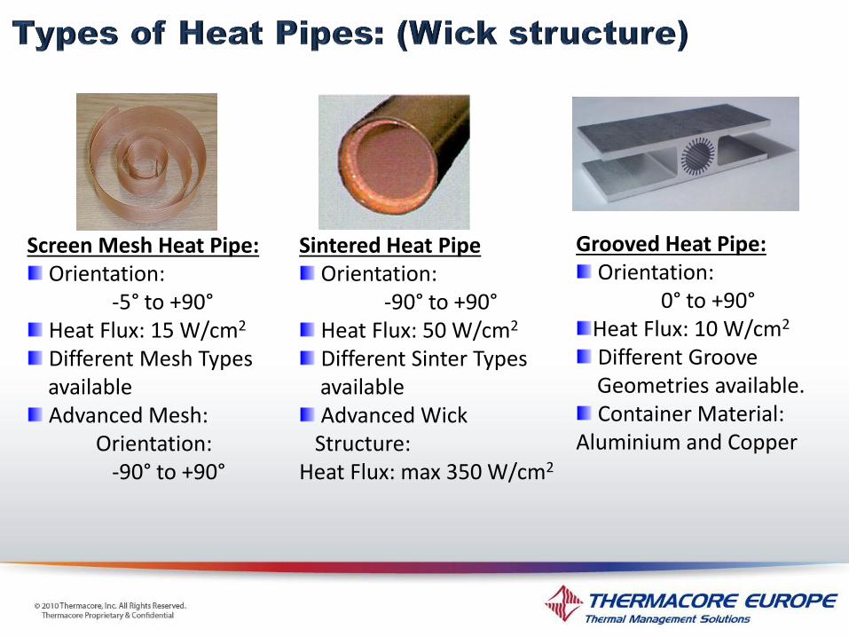
Grooved Heat Pipe: Orientation:
0° to +90° Heat Flux: 10 W/cm2 Different Groove
Geometries available. Container Material:
Aluminium and Copper
Screen Mesh Heat Pipe: Orientation:
-5° to +90° Heat Flux: 15 W/cm2 Different Mesh Types
available Advanced Mesh:
Orientation: -90° to +90°
Sintered Heat Pipe Orientation:
-90° to +90° Heat Flux: 50 W/cm2 Different Sinter Types
available Advanced Wick
Structure: Heat Flux: max 350 W/cm2

0
1
2
3
4
5
6
7
8
9
10
11
12
13
14
15
16
17
18
19
20
21
-300 -100 100 300 500 700 900 1100 1300 1500 1700 1900 2100
Temperature (C)
Silver
Lithium
Sodium
NaK
Potassium
Cesium
Water
Acetone
Carbon Dioxide
Ammonia
Methanol
Methylamine
Pentane
Propylene Ethane
Methane Nitrogen
Oxygen
Neon
Hydrogen
Helium
Ammonia heat pipes and AGHPs
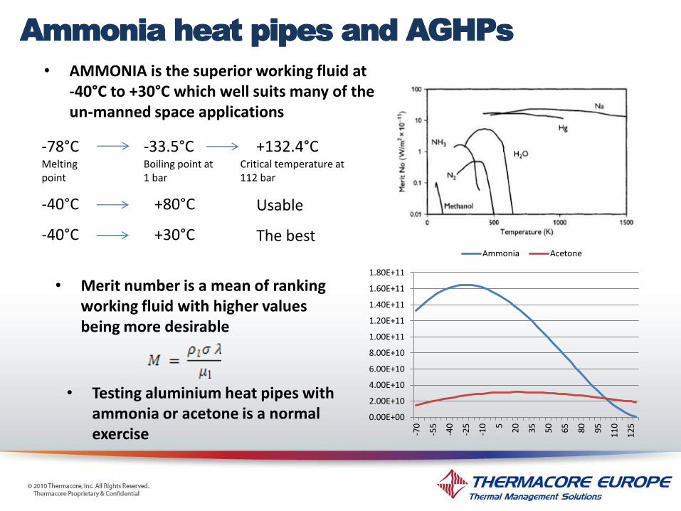
• AMMONIA is the superior working fluid at -40°C to +30°C which well suits many of the un-manned space applications
-78°C -33.5°C +132.4°C
-40°C +80°C Usable
-40°C +30°C The best
• Merit number is a mean of ranking working fluid with higher values being more desirable
Melting point
Boiling point at 1 bar
Critical temperature at 112 bar
0.00E+00
2.00E+10
4.00E+10
6.00E+10
8.00E+10
1.00E+11
1.20E+11
1.40E+11
1.60E+11
1.80E+11
-70
-55
-40
-25
-10
5
20
35
50
65
80
95
11
0
12
5
Ammonia Acetone
• Testing aluminium heat pipes with ammonia or acetone is a normal exercise
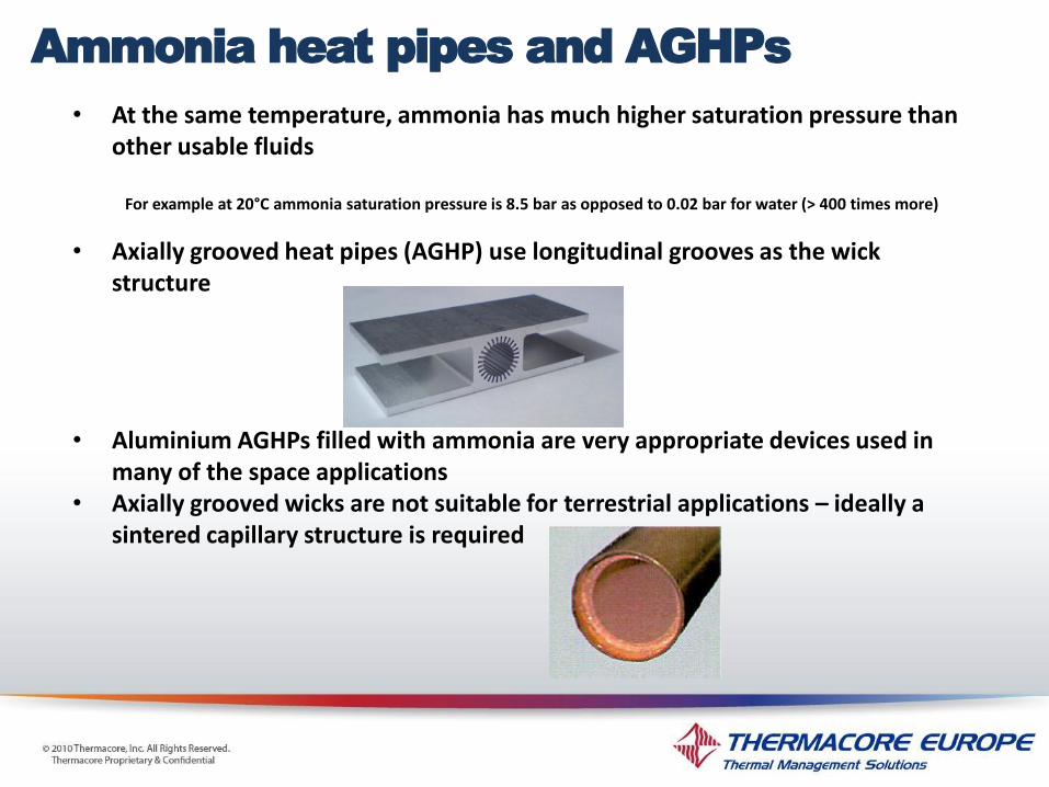
• At the same temperature, ammonia has much higher saturation pressure than other usable fluids
For example at 20°C ammonia saturation pressure is 8.5 bar as opposed to 0.02 bar for water (> 400 times more)
• Axially grooved heat pipes (AGHP) use longitudinal grooves as the wick structure
• Aluminium AGHPs filled with ammonia are very appropriate devices used in many of the space applications
• Axially grooved wicks are not suitable for terrestrial applications – ideally a sintered capillary structure is required
Ammonia heat pipes and AGHPs

Axially grooved heat pipes (AGHP)
Astrium Telecommunications Satellite Platform
In space, ammonia heat pipes are used for:
• Iso-thermalisation of the radiator panels • Transferring heat from the electronics to
the panels

Current space aluminium AGHPs specs
•Diameters (mm) 9 to 25 •Lengths (m) 0.25 to 4 •Linear mass (g/m) for filled heat pipes 20 to 670 •Heat transport capacity (Wm) 50 to 600 •Maximum heat flux density (W/cm2) 3 to 6* •Operating temperature range (°C) -40 to +80 •Life time (years) 15 to 20 (lifetime of space application)
•But the low surface heat flux of AGHP is now limiting deployment of high specification electronic components, which in turn limits the capabilities of the space-based sensing and communications systems. *Although the author was not able to locate any report of an actual ammonia heat pipe with higher heat fluxes than 3.36 W/Cm2 but even
the value of 6W/Cm2 (reported above from Hoa, Demolder et al. (2003)) is much lower than is expected from a sintered HP. (Some literature mention 5W/cm2 as the max)
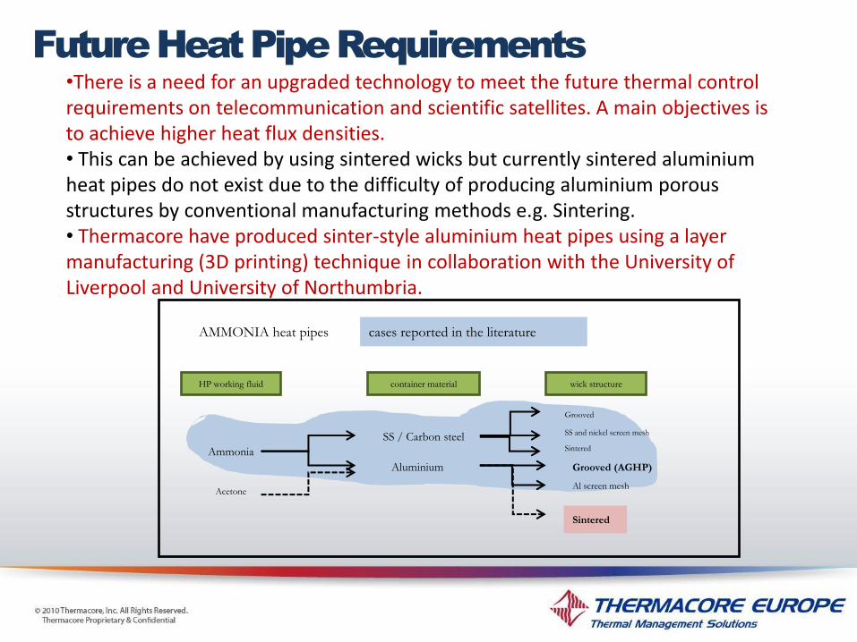
•There is a need for an upgraded technology to meet the future thermal control requirements on telecommunication and scientific satellites. A main objectives is to achieve higher heat flux densities. • This can be achieved by using sintered wicks but currently sintered aluminium heat pipes do not exist due to the difficulty of producing aluminium porous structures by conventional manufacturing methods e.g. Sintering. • Thermacore have produced sinter-style aluminium heat pipes using a layer manufacturing (3D printing) technique in collaboration with the University of Liverpool and University of Northumbria.
Acetone
AMMONIA heat pipes
HP working fluid wick structure container material
Ammonia
SS / Carbon steel
Aluminium
SS and nickel screen mesh
Grooved (AGHP)
Sintered
cases reported in the literature
Grooved
Sintered
Al screen mesh
Future Heat Pipe Requirements
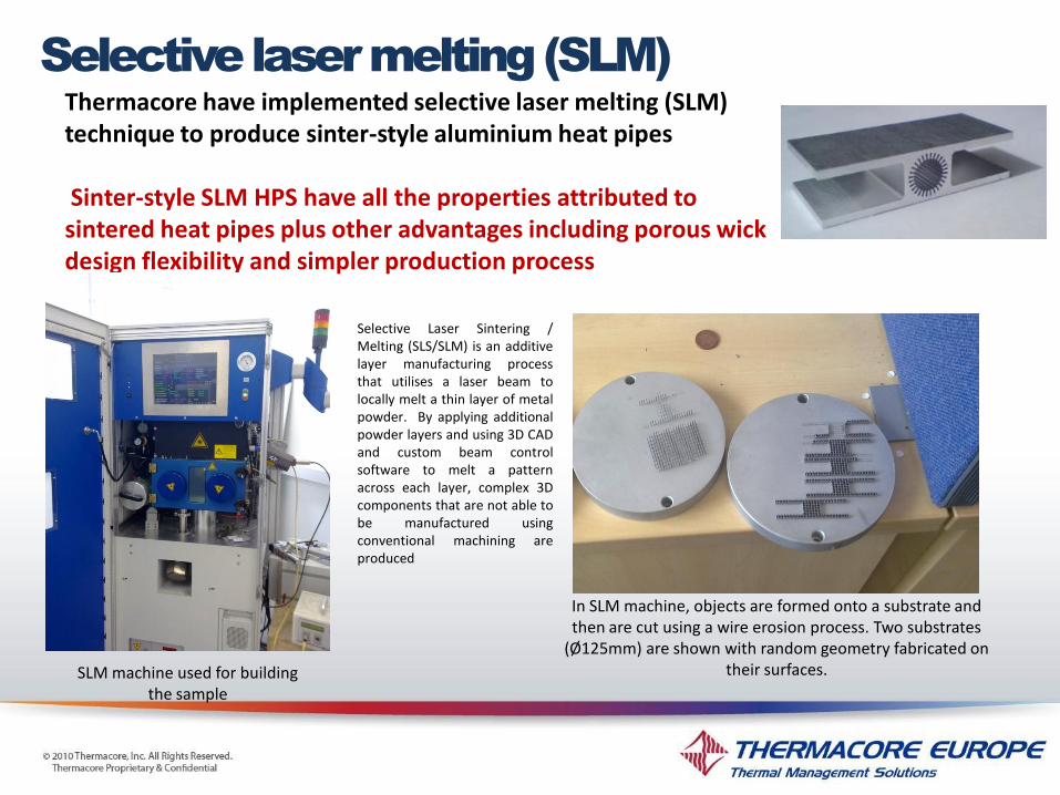
Thermacore have implemented selective laser melting (SLM) technique to produce sinter-style aluminium heat pipes Sinter-style SLM HPS have all the properties attributed to sintered heat pipes plus other advantages including porous wick design flexibility and simpler production process
Selective Laser Sintering / Melting (SLS/SLM) is an additive layer manufacturing process that utilises a laser beam to locally melt a thin layer of metal powder. By applying additional powder layers and using 3D CAD and custom beam control software to melt a pattern across each layer, complex 3D components that are not able to be manufactured using conventional machining are produced
SLM machine used for building the sample
In SLM machine, objects are formed onto a substrate and then are cut using a wire erosion process. Two substrates
(Ø125mm) are shown with random geometry fabricated on their surfaces.
Selective laser melting (SLM)
© Thermacore Europe Ltd. All Rights Reserved.
Thermacore Proprietary and Confidential. P24
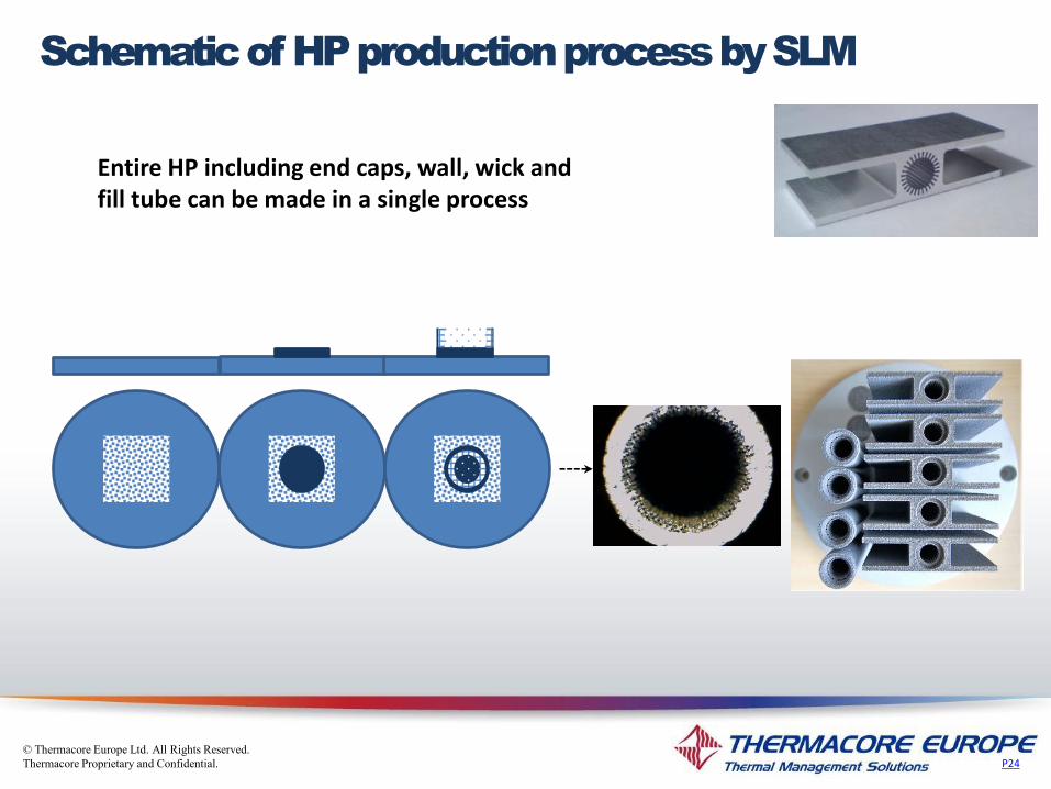
Entire HP including end caps, wall, wick and fill tube can be made in a single process
Schematic of HP production process by SLM

© Thermacore Europe Ltd. All Rights Reserved.
Thermacore Proprietary and Confidential.
SLM build parameters - Laser beam power
- laser beam movement
- laser beam ON-OFF time
- Inert gas
- Build direction
- Build strategy – specimen supports
SLM solid structures - Used to build heat pipes container, end cap and fill tube
- Highest achievable density is the main concern
- Hardness and morphology (X-ray) - Aluminium AGHP’s
SLM porous structures - Used to build heat pipe sinter-style wick
- Porosity, permeability and pore size are the main design parameters
- Shock and vibration resistance
SLM material
- Not all the materials can be used in SLM process
- Not all the aluminium alloys can be used in SLM process
- Titanium, SS and aluminium silicon alloys are among the suitable material
- AL6061 and 6063 alloys need more investigation in order to determine suitable SLM machine
build parameters
- Contact angle and compatibility (for use in heat pipe)
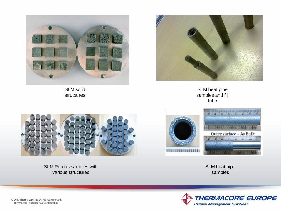
SLM solid
structures
SLM Porous samples with
various structures
SLM heat pipe
samples
SLM heat pipe
samples and fill
tube

Arterial wick heat pipe made by SLM (14mm OD diameter and 70mm length)
SLM heat pipe samples porous grooved wick SLM heat pipe samples porous grooved wick
SLM porous sample - regular SLM porous sample - regular SLM porous sample - random

© Thermacore Europe Ltd. All Rights Reserved.
Thermacore Proprietary and Confidential.
SLM porous bits are made using a lattice structure which can be
regular or random
P25
SLM porous structures

1. 300µm regular 2. 300µm random 3. 500µm regular 4. 500µm random 5. 700µm regular 6. 700µm random
SLM porous structures
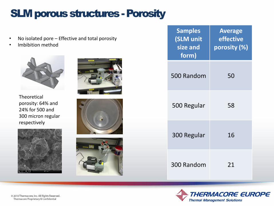
• No isolated pore – Effective and total porosity • Imbibition method
Theoretical porosity: 64% and 24% for 500 and 300 micron regular respectively
SLM porous structures - Porosity
Samples (SLM unit size and
form)
Average effective
porosity (%)
500 Random 50
500 Regular 58
300 Regular 16
300 Random 21
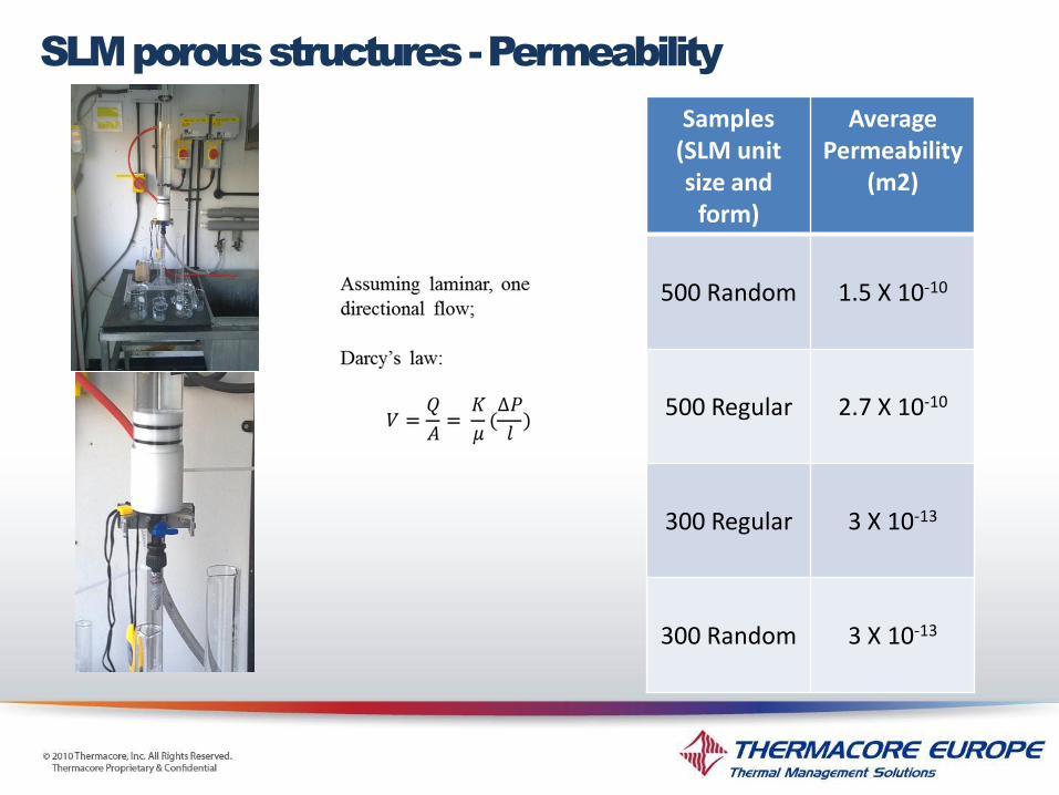
SLM porous structures - Permeability
Samples (SLM unit size and
form)
Average Permeability
(m2)
500 Random 1.5 X 10⁻¹⁰
500 Regular 2.7 X 10⁻¹⁰
300 Regular 3 X 10-13
300 Random 3 X 10-13

Diameter of the largest sphere that contains this point while still remaining entirely within the pore space
Theoretical Pore radii for 500 and 300 regular structures, 140 and 60 microns respectively. Not possible for random structures
pore radius measured on a 60X magnified image of a 500 micron regular SLM porous structure. Blue circle surface area value corresponds to around 140
micron radius (the circle has been drawn and measured on the scaled magnified picture and then that area has enlarged in the inset)
SLM porous structures – Pore size
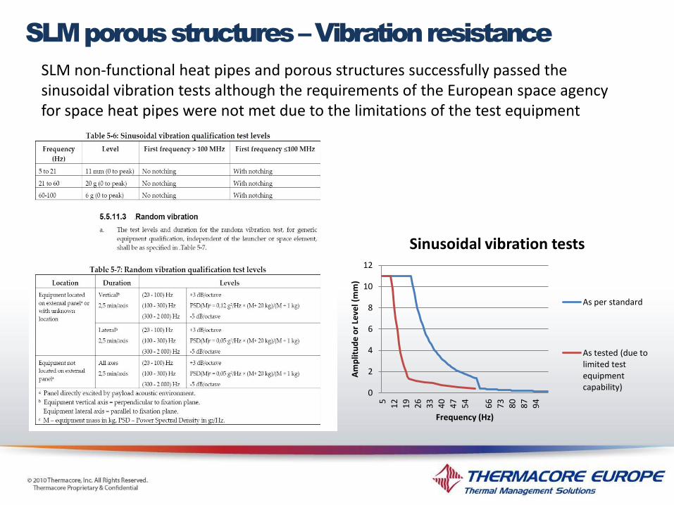
SLM porous structures – Vibration resistance
0
2
4
6
8
10
12
5
12
19
26
33
40
47
54
66
73
80
87
94
Am
plit
ud
e o
r Le
vel (
mm
)
Frequency (Hz)
Sinusoidal vibration tests
As per standard
As tested (due to limited test equipment capability)
SLM non-functional heat pipes and porous structures successfully passed the sinusoidal vibration tests although the requirements of the European space agency for space heat pipes were not met due to the limitations of the test equipment

SLM heat pipe sample used for analysis of the SLM solid
structures’ density using SEM. Scanned area indicated
Solid surface under microscope – 400 times magnified –
no pore can be seen
Solid surface under microscope – 800 times magnified –
no pore can be seen
Under electronic microscope pores are not observed but on the machined surface (top picture) pores can be seen with the naked eye.
SLM solid structures

SEM - XRF
P25
SLM – Powder material
Acetone contact angle measurement
SEM results reveal an important concern in using SLM technique to produce aluminium HPs. Titanium traces revealed here are thought to be the tiny titanium particles left in the environment or in the SLM machine from previous productions. This can potentially lead to major incompatibility problems and generation of NCGs in heat pipes.
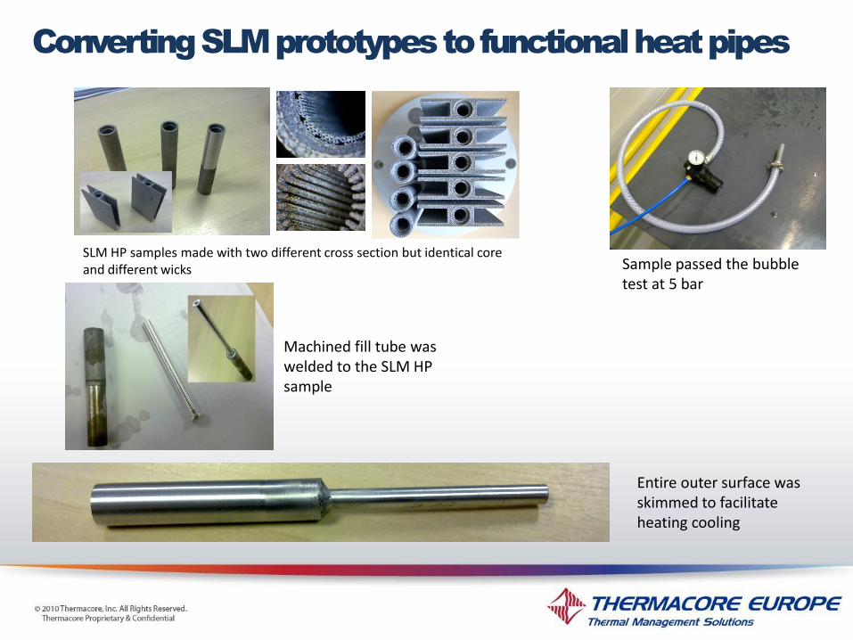
SLM HP samples made with two different cross section but identical core and different wicks
Machined fill tube was welded to the SLM HP sample
Entire outer surface was skimmed to facilitate heating cooling
Sample passed the bubble test at 5 bar
Converting SLM prototypes to functional heat pipes
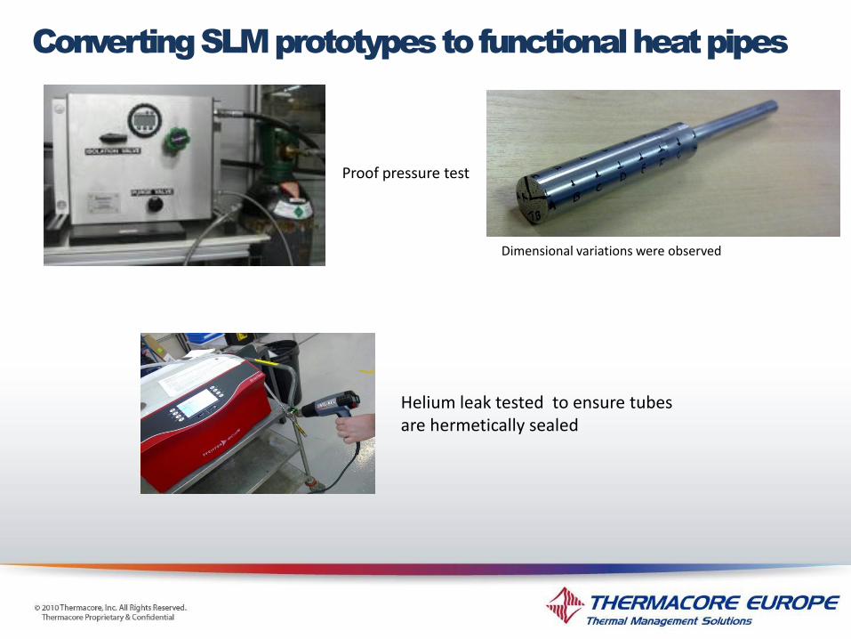
Proof pressure test
Dimensional variations were observed
Converting SLM prototypes to functional heat pipes
Helium leak tested to ensure tubes are hermetically sealed
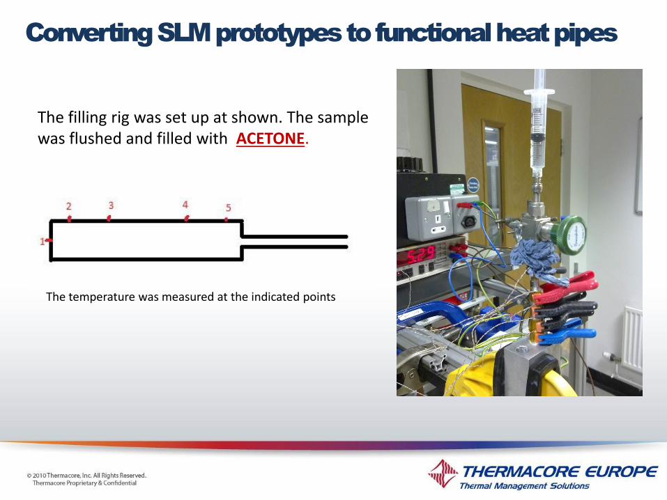
The filling rig was set up at shown. The sample was flushed and filled with ACETONE.
The temperature was measured at the indicated points
Converting SLM prototypes to functional heat pipes
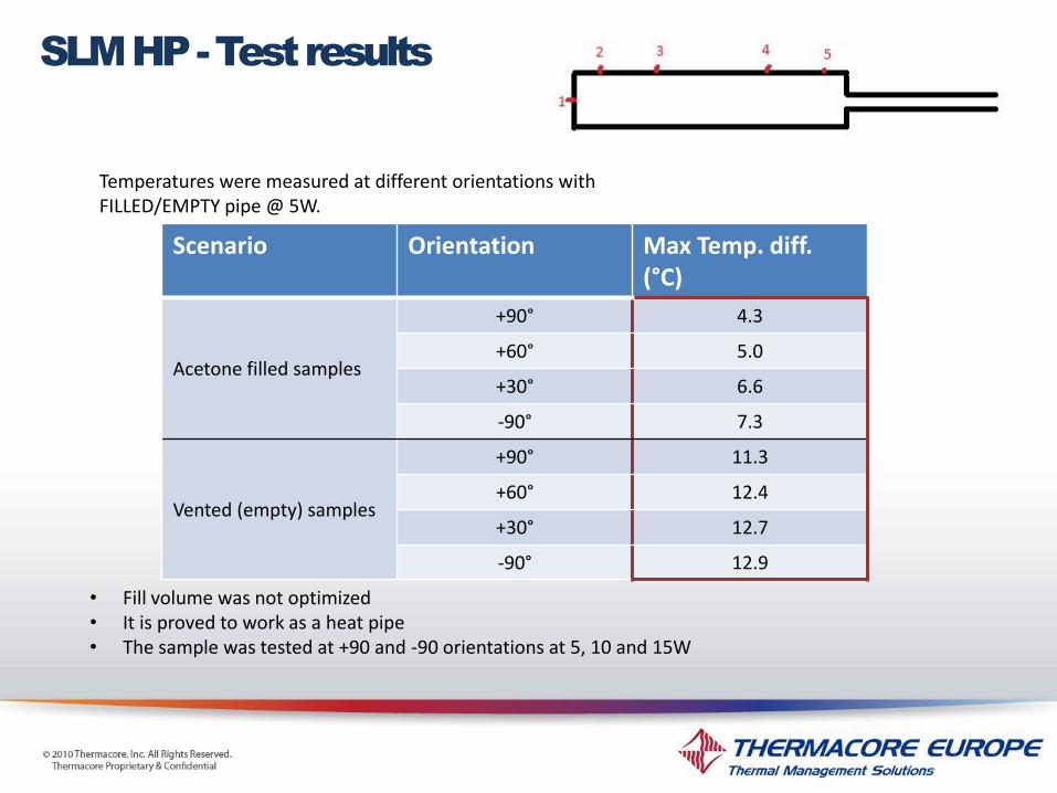
Temperatures were measured at different orientations with FILLED/EMPTY pipe @ 5W.
• Fill volume was not optimized • It is proved to work as a heat pipe • The sample was tested at +90 and -90 orientations at 5, 10 and 15W
SLM HP - Test results
Scenario Orientation Max Temp. diff. (°C)
Acetone filled samples
+90° 4.3
+60° 5.0
+30° 6.6
-90° 7.3
Vented (empty) samples
+90° 11.3
+60° 12.4
+30° 12.7
-90° 12.9

Once SLM heat pipe were proved to be feasible, and after optimizing the SLM build parameters, prototypes were produced with an external profile identical to a current Thermacore extruded AGHP profile.
Both the SLM samples and extruded AGHPs were machined to the final required shape and welded to the fill tube
SLM HP – Further development

Two SLM HPs and two extruded AGHPs were tested in the final thermal test rig for different powers and orientations (all the tests with acetone)
SLM HP – Further development
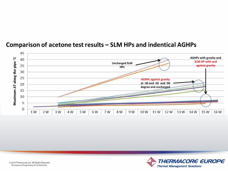
Uncharged SLM HPs
AGHPs against gravity at -30 and -50 and -90 degree and uncharged
AGHPs with gravity and SLM HP with and
against gravity

• SLM HPs have the main characteristic of the sintered heat pipe. They work against gravity and their performance is a lot less dependent on the orientation than the AGHPS • Uncharged SLM HPs show a higher thermal resistance (lower conductivity) than AGHPs made of Al6063. This can be due to the lower thermal conductivity of the AlSi12 powder material used in SLM and the pores left in the solid structures • Assuming an acceptable ∆T of < 5°C, and the geometry of the tested heat pipes and power, with an evaporator area of 1.7 Cm2, SLM heat pipes show an input heat flux of minimum 7 W/Cm2 at -30° against gravity which is at least twice the reported values for the heat input flux of the real AGHPs (with ammonia)at near horizontal orientation. • Temperature drop along the adiabatic length of a heat pipe is negligible so the measured ∆T and heat input fluxes are not to increase considerably for longer SLM heat pipes. • The same experiments on the ammonia filled pipes is an on-going activity. Considering the much higher merit number of ammonia compared to acetone, the total heat transfer capability of the pipes are expected to increase considerably which will increase the above values accordingly.
Conclusions
Other advantages of the SLM heat pipes
• SLM can be used for other materials as well as aluminium therefore it can be an alternative heat pipes manufacturing method for producing different heat pipes with some advantages over the conventional manufacturing method • SLM porous structures are generated from a CAD model allowing them to be graded / tailored with different porosity, permeability and pore sizes in different sections of a heat pipe to meet the needs of the specific application. •In addition to the higher heat input flux of the sintered or sinter-style wick structures, they also enable the heat pipe to work against gravity and provide a better condensate distribution in the evaporator section. These two latter characteristics can benefit many of the current terrestrial applications of ammonia heat pipes including permafrost, de-icing and heat recovery heat exchangers.

Challenges
• SLM build parameters still need to be improved to achieve a 100% density in solid structures • Achieving very small pore effective pore sized along with the optimum porosity and permeability simultaneously in the SLM porous structures needs better control on the power and movement of the laser beam • The SLM best build direction/strategy for heat pipes needs to be further investigated • Currently SLM HPs’ length is limited to a range of few centimetres to potentially one meter depending on the model of the used SLM machine and the build strategy • Compatibility tests have to be conducted for ammonia and the currently used SLM aluminium alloy of AlSi12 to investigate the possible reaction between its silicon content and ammonia which can lead to generation of non condensable gasses (NCGs) • Traces of Titanium were observed in the SEM of the produced heat pipes. Titanium is believed to be left in the SLM lab environment or inside the SLM machine from previous productions. This can lead to major problems in heat pipes due to incompatibility and generation of NCGs

Thank
you