Embed Size (px)
Citation preview

Instruction manual
Control UnitADN CU1
Contents
Contents
For your safety .................................................................................................................... 1
The ADN CU1 central unit ................................................................................................. 2
Package contents ............................................................................................................... 3
Components required for operation ............................................................................... 4
Product overview ADN CU1 central unit ........................................................................ 5
Structuring and controlling the conference system .................................................... 7
Structuring a wired conference system ..................................................................... 7
Setting up a wireless conference system ................................................................ 10
Configuring and controlling the conference system ............................................. 11
Input and output of audio signals ............................................................................ 11
Integration into a media control system ................................................................. 11
Preparing the ADN CU1 central unit for operation .................................................... 12
Setting up the central unit on a flat surface ........................................................... 12
Connecting the central unit to the mains power supply ...................................... 12
Setting up the conference system ................................................................................ 13
Setting up a small wired conference system with only the central unit ........... 14
Setting up a large wired conference system .......................................................... 15
Setting up a wireless conference system ................................................................ 16
Preparing to use the “Conference Manager” software ......................................... 17
Connecting external audio devices to the central unit ......................................... 18
Connecting a USB mass storage device for audio recordings
to the central unit ........................................................................................................ 18
Using the ADN CU1 central unit ..................................................................................... 18
Switching the conference system on/off ................................................................ 18
Deactivating the lock mode of the central unit ...................................................... 19
Functions of the keys .................................................................................................. 19
Setting the volume of the conference units’ built-in loudspeakers ................... 20
Configuring the conference system .............................................................................. 20
Working with the operating menu ........................................................................... 20
Overview of the operating menu .............................................................................. 22
Cleaning and maintaining the conference system .................................................... 27
Specifications ADN CU1 ................................................................................................... 28
For your safety
Please make sure to read the “Safety information” supplement included separately
with the product. This supplement contains important information on the safe
operation of the product as well as the manufacturer’s declaration and warranty
notes.
A detailed instruction manual for the overall ADN conference system can be found
• on the Internet at www.sennheiser.com or
• on the DVD-ROM supplied with the ADN CU1 central unit.
www Manual
ADN CU1 | 1

The ADN CU1 central unit
The ADN CU1 central unit
The ADN CU1 central unit is part of the Sennheiser ADN conference system.
The central unit controls the operation of the entire conference system. For wired
operation, up to max. 40 ADN D1 delegate units and ADN C1 chairperson units can
be directly connected to the central unit. For larger wired conference systems with
up to max. 400 conference units, the central unit can also manage up to 15 ADN PS
power supplies which in turn supply power the wired conference units.
For wireless conferencing, you can operate up to 150 ADN-W C1 and ADN-W D1
wireless conference units. For this, you require at least one ADN-W AM antenna
module per central unit. With one antenna module, you can operate a maximum of
75 wireless conference units. Depending on room conditions, you may require sev-
eral antenna modules. Please note that you can connect a maximum of four
antenna modules to one central unit.
For configuring the conference system, you can either use the central unit’s oper-
ating menu or the “Conference Manager” software. However, the full functionality
of a wireless conference system can only be configured using the “Conference Man-
ager” software. The software also allows you to control and monitor conferences
via a graphical interface.
Overview of a wired conference system
ADN C1 and ADN D1 wired conference units and ADN-W C1 and ADN-W D1
wireless conference units can be combined arbitrarily as long as you ensure
correct set-up and cabling and comply with the specifications (a conference
system can comprise a total of 400 conference units of which up to 150 can
be wireless).
ADN PS ADN PS
“Conference Manager”software
ADN CU1
max. 40ADN D1/ADN C1
max. 15 ADN PSmax. 400
ADN D1/ADN C1
per ADN PS with standard cabling a max. of 70
ADN D1/ADN C1
per ADN PS with redundant ring cabling a max. of 40
ADN D1/ADN C1
Conferences with up to a max. of 40 participants Conferences with up to a max. of 400 participants
2 | ADN CU1
Package contents
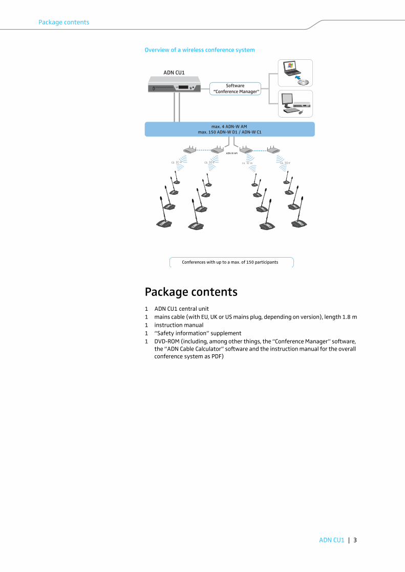
Overview of a wireless conference system
Package contents
1 ADN CU1 central unit
1 mains cable (with EU, UK or US mains plug, depending on version), length 1.8 m
1 instruction manual
1 “Safety information” supplement
1 DVD-ROM (including, among other things, the “Conference Manager” software,
the “ADN Cable Calculator” software and the instruction manual for the overall
conference system as PDF)
max. 150 ADN-W D1/ ADN-W C1
Software “Conference Manager”
ADN CU1
Conferences with up to a max. of 150 participants
max. 4 ADN-W AM max. 150 ADN-W D1 / ADN-W C1
ADN-W AM
ca. 30 m ca. 30 mm ca. 30 m ca. 30 m
ADN CU1 | 3

Components required for operation
4 | ADN CU1
Components required for operation
Central unit
Wired standard components
Power supplies
Conference units
System cables The system cables are black and have two shielded RJ45 plugs.
Wireless components
Antenna module
Wireless conference units
Number Description Cat. No. Function
1 ADN CU1-EU central unit,
EU version
505553 Controls the conference
(wired and wireless
components) and
supplies power to a max. of
40 conference units and/or
one antenna module
ADN CU1-UK central unit,
UK version
505554
ADN CU1-US central unit,
US version
505555
Number Description Cat. No. Function
1 - 15
(optional)
ADN PS-EU power supply,
EU version
505546 Supplies power to conference
units connected in simple
strings or in redundant ring
topology,
for conferences with up to
400 conference units
ADN PS-UK power supply,
UK version
505547
ADN PS-US power supply,
US version
505548
Number Description Cat. No. Function
max. 400 ADN D1 delegate unit 502758 Allows to make contributions
to the conference
1 - 10
(optional)
ADN C1 chairperson unit 502759 Allows to manage the
conference
Number Description Cat. No. Function
Divers SDC CBL RJ45-2, 2 m 009842 Allows to interconnect
components and conference
unitsSDC CBL RJ45-3, 3 m 009843
SDC CBL RJ45-5, 5 m 009844
SDC CBL RJ45-10, 10 m 009845
SDC CBL RJ45-20, 20 m 009846
SDC CBL RJ45-50, 50 m 009847
Number Description Cat. No. Function
1 -4 ADN-W AM antenna module 504743 Allows to transmit data via
RFADN-W AM-US antenna
module, US version
505715
Number Description Cat. No. Function
max. 150 ADN-W D1 wireless delegate
unit
504748 Allows to make contributions
to the conference
1 - 10
(optional)
ADN-W C1 wireless
chairperson unit
504745 Allows to manage the
conference
depending
on the
number of
wireless
conference
units
ADN-W BA battery pack 504744 Supplies power to wireless
conference units
ADN-W MIC 15-39 504750 Gooseneck microphones to
make contributionsADN-W MIC 36-29 504751
ADN-W MIC 15-50 504752
ADN-W MIC 36-50 504753
Additional accessories for the ADN conference system can be found at
www.sennheiser.com.

Product overview ADN CU1 central unit
Product overview ADN CU1 central unit
A Front view
On/off switch
Standard display key
Display panel
Jog dial
ESC key (Escape)
B Rear view
IN audio input
OUT audio output
PORT II socket (RJ45) for
connection of conference units/
ADN PS/ADN-W AM
PORT I socket (RJ45) for
connection of conference units/
ADN PS/ADN-W AM
VGA monitor output
USB socket (x2)
Network socket (RJ45)
Fans
Mains socket
Type plate
Hazard warnings
IN –– AUDIO –– OUT
PORT II PORT I
100-240V~
50/60Hz 240W2x 52.8V 1.75A
ADN CU1
ESC
6 7 8 9 @ A B CF E
D
1 2 3 4 5
15
1
2
3
4
5
6
7
8
9
0
A
B
C
D
E
F
ADN CU1 | 5

Product overview ADN CU1 central unit
Overview of the ADN CU1 display panel
After switch-on, the central unit’s display shows progress bars (for the booting
routine “Booting...” and the self test “Self-Test...”) and then the standard display:
For information on troubleshooting when error icons to are displayed, refer
to the ADN system manual.
Text/icon Possible display/function
Conference mode Current conference mode: “Direct Access”, “Override”,
“Push To Talk”, “Request”
Floor channel volume Current volume setting for the conference units’ built-
in loudspeakers
Number of
conference units
Number of conference units (wired or wireless)
connected to the conference system
Connection status icon Central unit is not connected to the “Conference
Manager” software and/or a media control unit.
Central unit is connected to the “Conference
Manager” software and/or a media control unit.
Structural change icon Icon appears when, since the last initialization, a
malfunction/change has occurred in the cabling
of the conference units.
Cable fault icon Icon appears when a conference unit is not
correctly connected to the ADN CU1 central unit.
Short-circuit icon Icon appears when there is a short circuit in the
cabling of the conference units. The display panel
lights up red.
Warning triangle Icon appears when there is a malfunction/
change. In case of malfunction, the display panel
lights up red.
Audio recording icon Icon appears when audio recording of the
conference is activated.
Icon flashes when storage space is low.
Icon appears when, after finishing the audio
recording, data is still written to the mass storage
device.
Icon appears when the audio recording failed. The
display panel lights up red.
Lock mode icon (see
page 19)
Lock mode of the central unit is deactivated.
Lock mode of the central unit is activated.
Direct Access 30 D1/C1
22
G
MNOP
H I
L JK
G
H
I
J
K
L
M
N
O
P
K N
6 | ADN CU1

Structuring and controlling the conference system
Structuring and controlling the
conference system
Structuring a wired conference system
Basic requirements for a conference system comprising wired conference units
For safe operation of the conference system, make sure that all wired conference
units are supplied with a voltage of at least 35 V! The voltage supplied depends on
the number of connected conference units and on the cable lengths. The standard
cable length between the central unit or power supply and the first conference unit
is 50 m max. and the standard cable length between the individual conference
units is 2 to 5 m.
If these cable lengths are observed, safe operation of conference systems with the
following number of conference units is ensured:
• small conference systems comprising only an ADN CU1 central unit
– 30-40 conference units connected in simple strings
• large conference systems comprising an ADN CU1 central unit and a max. of
15 ADN PS power supplies
– max. 400 conference units connected in simple strings or in ring topology
per ADN PS power supply
– 60-70 conference units connected in simple strings
– 30-40 conference units connected in ring topology
If cable lengths are shorter, it might be that more conference units can be used.
ADN D1 delegate units and ADN C1 chairperson units can be combined in an arbi-
trary order. The number of chairperson units, however, is limited to 10 max. per
conference system. All wired components of the conference system are intercon-
nected using SDC CBL RJ-45 system cables.
Calculating the voltage supply of the conference units
The “ADN Cable Calculator” software allows you to calculate the voltage supply of
the wired conference units on the individual sections of a cable string or cable ring
and to plan the structure of the conference system. The software is included on the
DVD-ROM (supplied with the ADN CU1) or is available from your Sennheiser part-
ner or from the “Downloads” area on the product page at www.sennheiser.com.
For further information on the installation and use of the “ADN Cable Calculator”
software, refer to the help section of the “ADN Cable Calculator” software and to
the ADN system manual.
ADN CU1 | 7

Structuring and controlling the conference system
8 | ADN CU1
Small conference system with simple cabling
For small conference systems with approx. 30-40 conference units, you require one
ADN CU1 central unit for controlling the conference. The conference units are inter-
connected in two cable strings which are directly connected to the central unit.
Large conference system with simple cabling
For setting up a large conference system with the maximum number of conference
units (i.e. up to 400), you require one ADN CU1 central unit for controlling the con-
ference and additional ADN PS power supplies for powering the conference units.
The conference units are interconnected in cable strings and up to four cable
strings can be connected to each ADN PS power supply.
PORT IPORT II
ADN CU1
max. 50 m approx. 2–5 m
52.8 V >35 V
20 1 2 3 ... approx. 2–5 m
max. 40ADN D1/ADN C1
ADN CU1
ADN CU1
ESC
ADN CU1
ESC
PORT
I/II
PORT
I 2
PORT
I 1 PO
RT II 1PORT II 2
ADN PS (max. 15)
ADN CU1
max. 50 m approx. 2–5 m approx. 2–5 m
52.8 V >35 V
20 1 2 3 ...max. 50 m
ADN CU1 ADN PS
max. 70ADN D1/ADN C1
ADN CU1
ESC
ADN CU1
ESC

Structuring and controlling the conference system
Large conference system with redundant ring topology
The redundant ring topology ensures that, should one conference unit or system
cable fail or be manipulated, all other conference units of the cable ring will
continue to function reliably.
For setting up a large conference system with redundant ring topology, you require
one ADN CU1 central unit for controlling the conference and additional ADN PS
power supplies for powering the conference units. The conference units are inter-
connected in rings and two rings can be connected to each ADN PS power supply.
When connecting the conference units to an ADN PS power supply, you can
mix different cable topologies (simple cabling with cable strings or redun-
dant ring topology) as long as you ensure correct cabling and comply with
the specifications.
PORT
I/II
ADN PS (max. 15)
ADN CU1
max. 50 m approx. 2–5 m approx. 2–5 m
52.8 V >35 V
20 1 2 3 ...max. 50 m
ADN CU1 ADN PS
max. 40ADN D1/ADN C1
PORT
I 2
PORT
I 1 PO
RT II 1PORT II 2
ADN CU1
ESC
ADN CU1
ESC
ADN CU1 | 9

Structuring and controlling the conference system
Setting up a wireless conference system
Basic requirements for a conference system comprising wireless conference units
The ADN-W C1 and ADN-W D1 wireless conference units connect wirelessly to the
ADN-W AM antenna module, which is connected to the ADN CU1 central unit via
system cable. The ADN-W AM antenna module can manage up to 75 wireless con-
ference units. The battery-powered wireless conference units are easy to use and
offer a high degree of flexibility. If the power supplied to the antenna module via
the system cable is not sufficient, you have to power the antenna module using the
NT 12-50C power supply.
Wireless conference system
For setting up a wireless conference system, you require one ADN CU1 central unit
for controlling the conference and at least one ADN-W AM antenna module for
operating the wireless conference units (range approx. 30 m).
ADN C1 and ADN D1 wired conference units and ADN-W C1 and ADN-W D1
wireless conference units can be combined arbitrarily as long as you ensure
correct set-up and cabling and comply with the specifications (a conference
system can comprise a total of 400 conference units of which up to 150 can
be wireless).
ADN-W AM
3214
max. 150 conference units per CU1max. 75 conference units per antenna
75...max. 50 m
ADN CU1 ADN-W AM
> 1 m > 0.5 m> 0.5 m > 0.5 m
PORT
II
PORT
I
10 | ADN CU1

Structuring and controlling the conference system
Configuring and controlling the conference system
For configuring the conference system, you can either use the operating menu of
the central unit or the “Conference Manager” software. However, the full function-
ality of a wireless conference system can only be configured using the “Conference
Manager” software. The software also allows you to control and monitor confer-
ences via a graphical interface.
The “Conference Manager” software can be run in two different ways:
1. As a program on the central unit’s built-in PC
You have to connect a screen, keyboard, and mouse to the central unit (see
page 17).
2. As a program on a Windows PC
You have to install the “Conference Manager” software on the PC and integrate
the PC together with the central unit in a network (see page 17).
Input and output of audio signals
Via XLR sockets, you can feed audio signals to the floor channel or output the floor
channel.
For recording a conference on a USB mass storage device, you can use the recording
function of the ADN CU1 central unit, which saves the floor channel and all channels
of the conference units as audio files in wav format.
Integration into a media control system
The ADN conference system can be completely integrated into a media control sys-
tem. You can monitor and control all functions of the conference system via the
programmable commands of your media control system. For information on the
integration into a media control system, refer to the ADN system manual.
Conference Manager software
ADN CU1
1 2 For information on the installation and use of the “ADN Cable Calculator”
software, refer to the ADN system manual.
ADN CU1 | 11

Preparing the ADN CU1 central unit for operation
Preparing the ADN CU1 central unit for
operation
Setting up the central unit on a flat surface
� Make sure that the air vents are not covered or blocked.
� Place the central unit on a flat surface as shown.
Connecting the central unit to the mains power supply
� First connect the connector of the mains cable (supplied) to the mains
socket .
� Connect the mains plug (EU, UK or US plug) of the mains cable to the mains
power supply.
The ADN CU1 central unit is now ready for operation.
For information on how to mount the central unit into a 19” rack, refer to
the ADN system manual.
CAUTION
Product damage due to unsuitable mains cables or power outlets!
An unsuitable power supply can damage the product.
� Only use the mains cable (supplied) for connecting the product to the mains
power supply.
� Only use multi-outlet power strips or extension cables with protective ground
contacts.
� Only use mains cables with a 3-pin connector.
100-240V~
50/60Hz 240W
D
15
D
12 | ADN CU1

Setting up the conference system
Setting up the conference system
Regardless of the number of conference units and the room size, we recommend
the following procedure for setting up the conference system:
� Decide if you require wired or mobile wireless conference units. You can also
combine wired and wireless conference units.
� Plan the number of conference units required for your conference system. A
total of 400 conference units (of which up to 150 can be wireless) can be used
in a conference system (the maximum number of ADN C1 or ADN-W C1 chair-
person units is limited to 10). Always take the largest possible number of par-
ticipants as a starting point.
If you are using wired conference units:
� Plan if simple cabling is sufficient or if you require a redundant ring topology
(see page 7).
� If necessary, calculate the number of ADN PS power supplies required (a maxi-
mum of 15 ADN PS power supplies can be used in a conference system).
� If necessary, calculate the maximum length of the cabling in order to ensure
that all conference units connected are supplied with sufficient voltage (see
page 7).
� Place the ADN CU1 central unit and, if necessary, the ADN PS power supplies
e.g. in the electrical equipment room or in the conference room.
� Place the conference units at the corresponding seats.
� Put out a sufficient number of SDC CBL RJ45 system cables in the required
lengths.
If you are using wireless conference units:
� Place the ADN CU1 central unit e.g. in the electrical equipment room or in the
conference room. If possible, place the ADN-W AM antenna module directly in
the conference room. The transmission range of the antenna module is approx.
30 m.
� Place the operational wireless conference units at the corresponding seats.
CAUTION
Product damage due to an unsuitable power supply!
If you connect standard network devices with RJ45 plugs (e.g. switches or network
cards) to the connection sockets PORT I , PORT II, DATA PS and / , the net-
work devices can be damaged due to an unsuitable power supply.
� Only connect ADN C1 and ADN D1 conference units, ADN PS power supplies and
the ADN-W AM antenna module to the connection sockets PORT I , PORT II, DATA
PS and / .
When connecting the conference units to an ADN PS power supply, you can
mix different cable topologies (simple cabling or redundant ring topology)
as long as you ensure correct cabling and comply with the specifications.
In some countries/regions (e.g. Canada), the use of wireless components
operating in the 5.15 to 5.25 GHz frequency band (channel 5 to 8) is
restricted to indoor use.
ADN CU1 | 13
Setting up the conference system
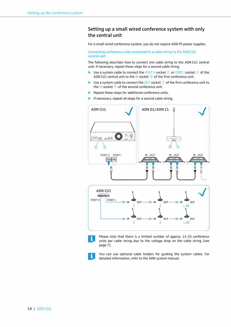
Setting up a small wired conference system with only
the central unit
For a small wired conference system, you do not require ADN PS power supplies.
Connecting conference units connected in a cable string to the ADN CU1
central unit
The following describes how to connect one cable string to the ADN CU1 central
unit. If necessary, repeat these steps for a second cable string.
� Use a system cable to connect the PORT II socket or PORT I socket of the
ADN CU1 central unit to the IN socket of the first conference unit.
� Use a system cable to connect the OUT socket of the first conference unit to
the IN socket of the second conference unit.
� Repeat these steps for additional conference units.
� If necessary, repeat all steps for a second cable string.
Please note that there is a limited number of approx. 15-20 conference
units per cable string due to the voltage drop on the cable string (see
page 7).
You can use optional cable holders for guiding the system cables. For
detailed information, refer to the ADN system manual.
8 9
<
A
<
IN OUT IN OUT IN OUTPORT II PORT I
ADN CU1 ADN D1/ADN C1
PORT I PORT II IN OUT IN OUT IN OUT
IN OUT IN OUT IN OUT
ADN CU1
IN –– AUDIO –– OUT
PORT II PORT I
100-240V~
50/60Hz 240W2x 52.8V 1.75A
8 9
INN OOOUUT INN OOOUUT INN OOOUUT
INN OOOUUT INN OOOUUT INN OOOUUT
20 1 2 ...
20 1 2 ...
< A
14 | ADN CU1
Setting up the conference system
Setting up a large wired conference system
For conference systems comprising more than 40 conference units or when the
conference units are connected in a redundant ring topology, you require ADN PS
power supplies. A maximum of 15 ADN PS power supplies can be used in a confer-
ence system.
Connecting ADN PS power supplies to the ADN CU1 central unit
� Use a system cable to connect the PORT II socket or PORT I socket of the
ADN CU1 central unit to the DATA CU/PS input socket of the first ADN PS
power supply (the maximum cable length allowed is 50 m).
� Use a system cable to connect the DATA PS output socket of the first ADN PS
power supply to the DATA CU/PS input socket of the second ADN PS power
supply.
� Repeat these steps for the remaining ADN PS power supplies.
� Connect the conference units to the ADN PS power supply (refer to the instruc-
tion manual of the ADN PS power supply or to the ADN system manual).
8 9
<
A
<
CU/PS
PS DATA
CU/PS
PS DATA
CU/PS
PS DATA
PORT II PORT I
ADN CU1
CU/PS PS
PORT I
1 2
PORT II
1 2
DATA
100 - 240V 50/60Hz 385W
PORT I & PORT II: max. 5.25A sum
ADN PS
IN –– AUDIO –– OUT
PORT II PORT I
100-240V~
50/60Hz 240W2x 52.8V 1.75A
8 9 < A
ADN CU1 | 15
Setting up the conference system
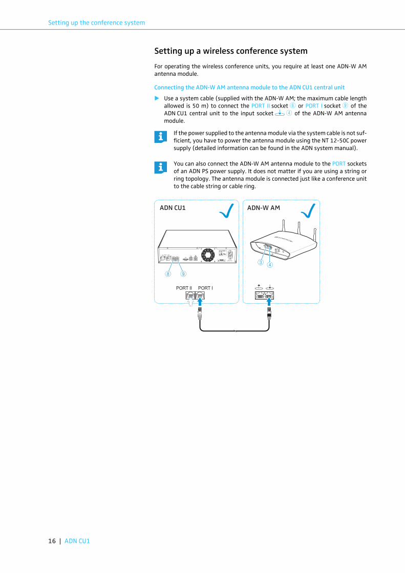
Setting up a wireless conference system
For operating the wireless conference units, you require at least one ADN-W AM
antenna module.
Connecting the ADN-W AM antenna module to the ADN CU1 central unit
� Use a system cable (supplied with the ADN-W AM; the maximum cable length
allowed is 50 m) to connect the PORT II socket or PORT I socket of the
ADN CU1 central unit to the input socket of the ADN-W AM antenna
module.
If the power supplied to the antenna module via the system cable is not suf-
ficient, you have to power the antenna module using the NT 12-50C power
supply (detailed information can be found in the ADN system manual).
You can also connect the ADN-W AM antenna module to the PORT sockets
of an ADN PS power supply. It does not matter if you are using a string or
ring topology. The antenna module is connected just like a conference unit
to the cable string or cable ring.
8 9
4
PORT II PORT I
ADN CU1
IN –– AUDIO –– OUT
PORT II PORT I
100-240V~
50/60Hz 240W2x 52.8V 1.75A
8 9
ADN-W AM
43
16 | ADN CU1

Setting up the conference system
Preparing to use the “Conference Manager” software
Running the software installed on the central unit
To use the “Conference Manager” software installed on the central unit, you require
the following devices:
� Use a Sub-D VGA cable to connect a screen to the VGA monitor output .
� Connect the keyboard and the mouse to the two USB sockets .
� Configure the screen, the keyboard and the mouse using the “Conference Man-
ager” software (for detailed information, refer to the ADN system manual).
Running the software on a separate Windows PC
To run the “Conference Manager” software on a separate Windows PC, the PC must
meet the following system requirements:
� Use a network cable (Cat5) to connect the Ethernet socket of the central unit
to the network interface of your PC.
You can also connect the PC and the central unit using a switch or similar.
� Install the “Conference Manager” software supplied on the DVD-ROM on your
connected PC and configure the network (for detailed information, refer to the
ADN system manual).
IN –– AUDIO –– OUT
PORT II PORT I
100-240V~
50/60Hz 240W2x 52.8V 1.75A
0
IN –– AUDIO –– OUT
PORT II PORT I
100-240V~
50/60Hz 240W2x 52.8V 1.75A
A
Device Requirements
Screen Connection: 15-pin Sub-D VGA
Resolution: 800 x 600 pixels or higher
1024 x 768 or 1280 x 1024 pixels recommended
Mouse Standard USB for Windows PCs
Keyboard Standard USB for Windows PCs
Supported language layouts: e.g. English, German, French,
Spanish, Italian, Dutch, Russian, Chinese, Japanese (for the
complete list, refer to the ADN system manual)
Use a USB hub if the number of USB sockets on the central unit is not
sufficient.
<
A
A
IN –– AUDIO –– OUT
PORT II PORT I
100-240V~
50/60Hz 240W2x 52.8V 1.75A
B
Component Requirement
Processor Intel Pentium 4 or AMD Athlon XP, 2 GHz or more
RAM Min. 1 GB, depending on your operating system
Hard disk Min. 500 MB free hard disk memory
Drives DVD-ROM
Interfaces/network Ethernet 100 MBit/s
TCP/IP internet protocol Internet Protocol version 4 (IPv4)
Screen Minimum resolution: 800 x 600 pixels
Recommended: 1024 x 768 pixels
Operating system Microsoft Windows XP Professional with SP3
Microsoft Windows Vista with SP2
Microsoft Windows 7
Microsoft Windows 8
B
ADN CU1 | 17

Using the ADN CU1 central unit
18 | ADN CU1
Connecting external audio devices to the central unit
To output the floor channel via an external audio device:
� Use an XLR cable to connect the OUT audio output of the central unit to an
external audio device.
To connect an external audio source and to feed its signals to the floor channel:
� Use an XLR cable to connect the external audio source to the IN audio input
of the central unit.
Connecting a USB mass storage device for audio
recordings to the central unit
In order to be able to use the audio recording function of the ADN CU1 central unit,
you require a USB mass storage device with the following characteristics:
� Connect the USB mass storage device to one of the two USB sockets .
� If necessary, connect the mains unit of the USB mass storage device.
Using the ADN CU1 central unit
Switching the conference system on/off
Switching on a conference system comprising wired conference units
� On the ADN CU1 central unit and, if connected, on the ADN PS power supplies,
set the on/off switch to position “I”.
The central unit switches on and its display panel lights up. If ADN PS power
supplies are connected, they are also switched on.
Switching on a conference system comprising an antenna module for
wireless operation
� Set the on/off switch of the ADN CU1 central unit to position “I”.
The central unit switches on and its display panel lights up. The connected
ADN-W AM antenna module is also switched on.
IN –– AUDIO –– OUT
PORT II PORT I
2x 52.8V 1.75A
7
IN –– AUDIO –– OUT
PORT II PORT I
6
2x 52.8V 1.75A
7
6
USB mass storage device Requirements
Recommended memory
size
> 500 GB
File system NTFS, FAT32
Partition 1
Connection USB type A plug
Interface USB 2.0
Power supply via USB socket (approx. 500 mA) or separate
mains unit
IN –– AUDIO –– OUT
PORT II PORT I
100-240V~
50/60Hz 240W2x 52.8V 1.75A
HDD
A
Use a USB hub if the number of USB sockets is not sufficient or if the USB
mass storage device is too large for connection to the central unit.
A
A
ADN CU1
ADN CU1ESC
1
1
If you are using ADN PS power supplies in a conference system in which
wireless conference units are used, you have to switch on the ADN PS power
supplies as well (see previous section).
1

Using the ADN CU1 central unit
Switching off the conference system
� Set the on/off switch of the ADN CU1 central unit to position “0”.
The central unit is switched off and the display panel goes off. If ADN PS power
supplies are connected to the central unit and switched on, they are switched
off and the status LEDs go off. If an ADN-W AM antenna module is connected
to the central unit, it is also switched off.
To completely switch the ADN CU1 central unit off:
� Pull out the mains plug from the wall socket.
Deactivating the lock mode of the central unit
If the lock mode is activated, you have to deactivate it in order to be able to operate
the central unit:
Functions of the keys
If you have made changes to a configuration using the “Conference Man-
ager” software, you have to save these changes before switching the cen-
tral unit off. All other settings of the central unit are automatically saved.
1
� Press the jog dial or any other key.
“Lock” appears on the display panel.
� Turn the jog dial.
The “Off” setting is selected.
� Press the jog dial.
The lock mode is deactivated.
Action Functions
Press the ESC key • Cancels the entry and returns to the next higher
menu level or to the standard display
Press the jog dial • Changes from the standard display to the
operating menu
• Calls up a menu item
• Enters a submenu
• Stores the settings and returns to the operating
menu
Turn the jog dial • Increases or reduces the floor channel volume
(when the standard display is shown)
• Changes to the next/previous menu item
• Changes the setting of a menu item
Press the standard
display key
• Returns to the standard display
ADN CU1 | 19
Configuring the conference system
Setting the volume of the conference units’ built-in
loudspeakers
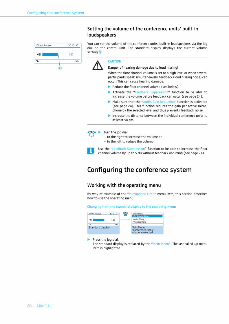
You can set the volume of the conference units’ built-in loudspeakers via the jog
dial on the central unit. The standard display displays the current volume
setting .
Configuring the conference system
Working with the operating menu
By way of example of the “Microphone Limit” menu item, this section describes
how to use the operating menu.
Changing from the standard display to the operating menu
� Press the jog dial.
The standard display is replaced by the “Main Menu”. The last called-up menu
item is highlighted.
Direct Access 30 D1/C1
20
H
CAUTION
Danger of hearing damage due to loud hissing!
When the floor channel volume is set to a high level or when several
participants speak simultaneously, feedback (loud hissing noise) can
occur. This can cause hearing damage.
� Reduce the floor channel volume (see below).
� Activate the “Feedback Suppression” function to be able to
increase the volume before feedback can occur (see page 24).
� Make sure that the “Audio Gain Reduction” function is activated
(see page 24). This function reduces the gain per active micro-
phone by the selected level and thus prevents feedback noise.
� Increase the distance between the individual conference units to
at least 50 cm.
� Turn the jog dial
– to the right to increase the volume or
– to the left to reduce the volume.
Use the “Feedback Suppression” function to be able to increase the floor
channel volume by up to 5 dB without feedback occurring (see page 24).
H
Main Menu; “Conference Menu” submenu selected
Standard display
Direct Access 30 D1/C1
20
Main Menu
Conference Menu
Audio Menu
Wireless Menu
20 | ADN CU1

Configuring the conference system
Calling up a menu item
� Press the jog dial to call up the “Conference Menu” menu item.
The “Conference Menu” submenu appears.
� Turn the jog dial to select the “Microphone Limit” menu item.
� Press the jog dial to call up the “Microphone Limit” menu item.
Changing and storing settings
� Turn the jog dial to adjust settings in the “Microphone Limit” menu item.
� Press the jog dial.
Your setting is stored. You are back to the operating menu.
Canceling an entry
Or:
To subsequently directly return to the last edited menu item:
Exiting the operating menu
Or:
Select and call up the “Microphone Limit” menu item
The “Microphone Limit” menu item is displayed
Conference Menu
Conference Mode
Microphone Limit
Request Limit
Microphone Limit
Conf. Mode
Microphones 05
No. Request
05 05
Select and call up the “Conference Menu” submenu
Main Menu
Conference Menu
Audio Menu
Wireless Menu
By briefly turning the jog dial to the left or right, the next or the previous
menu item or setting is displayed.
If you turn the jog dial to the left or right and hold it in this position, the
menu items or settings change in quick succession (“fast search” function).
Select the desired setting
Store the setting
Microphone Limit
Conf. Mode
Microphones 05
No. Request
Microphone Limit
Conf. Mode
Microphones 07
No. Request
05 05
Select and call up the “Microphone Limit” menu item
Conference Menu
Conference Mode
Microphone Limit
Request Limit
05
� Press the ESC key.
The operating menu or the next higher menu level appears.
� Press the standard display key.
The standard display appears.
� Press the jog dial repeatedly until the last edited menu item appears.
� Press the standard display key.
The standard display appears.
� Press the ESC key repeatedly until the standard display appears.
ADN CU1 | 21

Configuring the conference system
Overview of the operating menu
Conference MenuAudio MenuWireless MenuSystem Menu*LanguagesSettings
Main Menu
NetworkContrastLockRestore Factory Defaults
“Settings Menu”submenu
CountryChannel SelectionAccess ModeSwitch Off Wireless Units
“Wireless Menu” submenu
Conference ModeMicrophone LimitRequest LimitTalk Time StatusTalk Time LimitPremonition Time LimitReaction on Talktime ExceedBlink on RequestRe-InitClear Request List on Cancel
“Conference Menu” submenu
IP Address ModeIP AddressSubnet MaskGateway
“Network” submenu
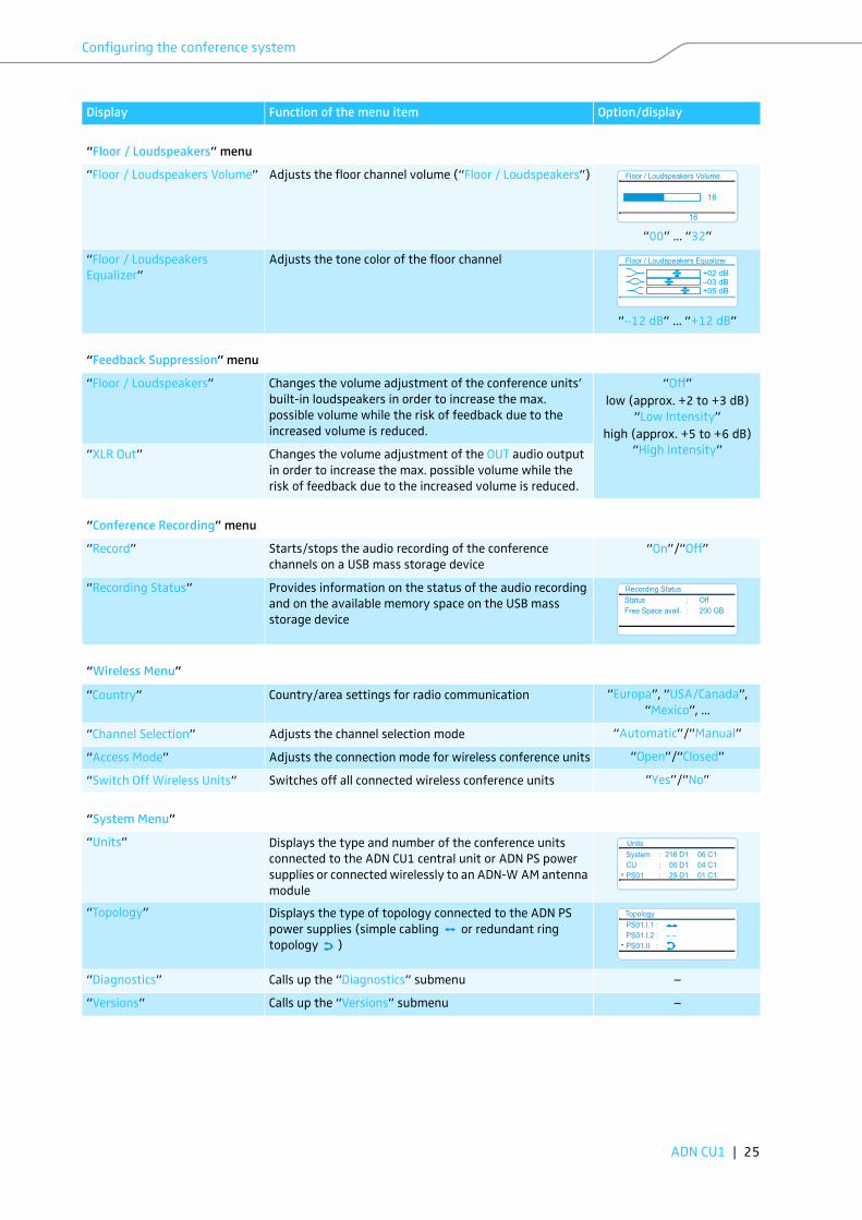
XLR OutXLR InFloor / LoudspeakersAudio Gain ReductionFeedback SuppressionXLR Mix MinusMic Loudspeaker MuteConference Recording
“Audio Menu” submenu
XLR Out StatusXLR Out VolumeXLR Out Equalizer
“XLR Out” submenu
XLR In StatusXLR In SensitivityXLR In Equalizer
“XLR In” submenu
Floor / Loudspeakers VolumeFloor / Loudspeakers Equalizer
“Floor / Loudspeakers” submenu
RecordRecording Status
“Conference Recording” submenu
Floor / LoudspeakersXLR Out
“Feedback Suppression” submenu
UnitsTopologyDiagnosticsVersions
“System Menu” submenu
System LoadTemperatureBus StatisticsStart Self-TestReset Break IndicationReset Error Indication
“Diagnostics” submenu
Hardware Version InfoSoftware Version Info
“Versions” submenu
22 | ADN CU1

Configuring the conference system
Display Function of the menu item Option/display
“Main Menu”
“Conference Menu” Calls up the “Conference Menu” submenu –
“Audio Menu” Calls up the “Audio Menu” submenu –
“Wireless Menu” Calls up the “Wireless Menu” submenu –
“System Menu” Calls up the “System Menu” submenu –
“*Languages” Adjusts the language “German”, “English”,
“Espanol”...
“Settings” Calls up the “Settings” submenu –
“Conference Menu”
“Conference Mode” Adjusts the conference mode
“Direct Access”, “Override” and “Push to talk”: These
conference modes do not require the use of a chairperson
unit. If the maximum number of speakers who can take
the floor simultaneously has not been reached, a further
speaker can take the floor immediately.
“Request”: For this mode to function, a chairman unit is
required. The chairperson receives requests to speak and
grants speaking privileges according to the FIFO principle
(First In – First Out), i.e. the participant with the longest
waiting time is granted speaking privileges.
“Direct Access”, “Override”,
“Push to talk” or “Request”
“Microphone Limit” Sets the maximum number of speakers who can take the
floor simultaneously for all conference modes
“1” ... “10”
“Request Limit” Sets the maximum number of requests to speak for
“Request” and “Direct Access” mode
“0” ... “10”
“Talk Time Status” Activates/deactivates the speaking time limit “On”/“Off”
“Talk Time Limit” Sets the speaking time limit “01” ... “60”
in steps of 1 minute
“Premonition Time Limit” Sets the advance warning time (warns speakers that they
are approaching the end of the individual speaking time)
“00” ... “120”
in steps of 10 seconds
“Reaction on Talktime Exceed” Determines the behavior when the individual speaking
time is exceeded
“Continue”: The individual speaking time is continued.
“Cancel”: The individual speaking time is terminated.
“Continue”/“Cancel”
“Blink on Request” Activates/deactivates the flashing of the signal light ring
when a request to speak is made
“On”/“Off”
“Re-Init” Re-initializes the conference units
If you connect ADN C1 or ADN-W C1 chairperson units to
the conference system during a running conference, you
have to re-initialize them. When conference units are re-
initialized, the conference will be interrupted.
“Yes”/“No”
“Clear Request List on Cancel” Sets the function of the priority key of the chairperson
unit
“On”: Pressing the priority key deactivates all ADN D1
or ADN-W D1 delegate units. All requests to speak are
deleted.
“Off”: Pressing the priority key deactivates all currently
active ADN D1 or ADN-W D1 delegate units. All requests to
speak are retained.
“On”/“Off”
ADN CU1 | 23

Configuring the conference system
“Audio Menu”
“XLR Out” Calls up the “XLR Out” submenu –
“XLR In” Calls up the “XLR In” submenu –
“Floor / Loudspeakers” Calls up the “Floor / Loudspeakers” submenu –
“Audio Gain Reduction” The sum signal of all active conference units is output via
the floor channel (“Floor / Loudspeakers”). The “Audio
Gain Reduction” menu item allows you to adjust how the
volume levels of the signals of the individual conference
units are processed.
“0.0 dB per Mic.” ...
“−3.0 dB per Mic.”,
“Linear Division”
“Feedback Suppression” Calls up the “Feedback Suppression” submenu –
“XLR Mix Minus” Activates the filtering of the IN audio input from the OUT
audio output in order to avoid, for example, double audio
signals during teleconferencing
“On”/“Off”
“Mic Loudspeaker Mute” Deactivates the conference units’ built-in loudspeakers
for contributions coming from the conference units’
microphones
“On”/“Off”
“Conference Recording” Calls up the “Conference Recording” submenu –
“XLR Out” menu
“XLR Out Status” Activates/deactivates the OUT audio output “On”/“Off”
“XLR Out Volume” Adjusts the volume of the XLR output
“01” ... “32”
“XLR Out Equalizer” Adjusts the tone color of the XLR output
“−12 dB” ... “+12 dB”
“XLR In” menu
“XLR In Status” Activates/deactivates the IN audio input “On”/“Off”
“XLR In Sensitivity” Adjusts the sensitivity of the XLR input
“−18.0 dBu” ... “+18.0 dBu”
“XLR In Equalizer” Adjusts the tone color of the XLR input
“−12 dB” ... “+12 dB”
Display Function of the menu item Option/display
XLR Out Volume
No
+ 6 dB
+ 6 dB
XLR Out Equalizer
No
+02 dB–03 dB+05 dB
XLR In Sensitivity
No
+07.5 dBu
+07.5 dBu
XLR In Equalizer
No
+02 dB–03 dB+05 dB
24 | ADN CU1
Configuring the conference system
“Floor / Loudspeakers” menu
“Floor / Loudspeakers Volume” Adjusts the floor channel volume (“Floor / Loudspeakers”)
“00” ... “32”
“Floor / Loudspeakers
Equalizer”
Adjusts the tone color of the floor channel
“−12 dB” ... “+12 dB”
“Feedback Suppression” menu
“Floor / Loudspeakers” Changes the volume adjustment of the conference units’
built-in loudspeakers in order to increase the max.
possible volume while the risk of feedback due to the
increased volume is reduced.
“Off”
low (approx. +2 to +3 dB)
“Low Intensity”
high (approx. +5 to +6 dB)
“High Intensity”“XLR Out” Changes the volume adjustment of the OUT audio output
in order to increase the max. possible volume while the
risk of feedback due to the increased volume is reduced.
“Conference Recording” menu
“Record” Starts/stops the audio recording of the conference
channels on a USB mass storage device
“On”/“Off”
“Recording Status” Provides information on the status of the audio recording
and on the available memory space on the USB mass
storage device
“Wireless Menu”
“Country” Country/area settings for radio communication “Europa”, “USA/Canada”,
“Mexico”, ...
“Channel Selection” Adjusts the channel selection mode “Automatic”/“Manual”
“Access Mode” Adjusts the connection mode for wireless conference units “Open”/“Closed”
“Switch Off Wireless Units” Switches off all connected wireless conference units “Yes”/“No”
“System Menu”
“Units” Displays the type and number of the conference units
connected to the ADN CU1 central unit or ADN PS power
supplies or connected wirelessly to an ADN-W AM antenna
module
“Topology” Displays the type of topology connected to the ADN PS
power supplies (simple cabling or redundant ring
topology )
“Diagnostics” Calls up the “Diagnostics” submenu –
“Versions” Calls up the “Versions” submenu –
Display Function of the menu item Option/display
Floor / Loudspeakers Volume
No
16
16
Floor / Loudspeakers Equalizer
No
+02 dB–03 dB+05 dB
Recording Status
No
Status : Off
Free Space avail. : 200 GB
Units
No
System : 216 D1 06 C1
CU : 00 D1 04 C1
PS01 : 29 D1 01 C1
Topology
No
PS01.I.1 :
PS01.I.2 : – –
PS01.II :
ADN CU1 | 25

Configuring the conference system
“Diagnostics” menu
“System Load” Provides information on the current supply (A), voltage
supply (V) and power (P)
“Temperature” Provides information on the temperature status
“Bus Statistics” Provides information on the status of data transmission/
errors
“Start Self-Test” Performs a self-test on the conference system “Yes”/“No“
“Reset Break Indication” Resets the error counter (“Break Counter”) in the “Bus
Statistics” menu item
“Yes”/“No”
“Reset Error Indication” Resets the display for data bus errors (“Error Indication”)
in the “Bus Statistics” menu item
“Yes”/“No”
“Versions” menu
“Hardware Version Info” Displays the hardware version
“Software Version Info” Displays the software version
“Settings” menu
“Network” Calls up the “Network” submenu –
“Contrast” Adjusts the contrast of the display panel “1” ... “15”
“Lock” Activates/deactivates the lock mode “On”/“Off”
“Restore Factory Defaults” Restores the factory default settings “Yes”/“No”
“Network” menu
“IP Address Mode” Sets the IP address allocation mode “Static IP”/“Dynamic IP”
“IP Address” Sets the IP address of the central unit “xxx . xxx . xxx . xxx”
“Subnet Mask” Sets the subnet mask of the central unit “xxx . xxx . xxx . xxx”
“Gateway” Sets the IP address of a standard gateway “xxx . xxx . xxx . xxx”
Display Function of the menu item Option/display
System Load
No
CU.I : – – A � V
PS07.II.1 : A – – V
PS07 : � P
Temperature
No
CU : �PS07 : �PS11 : �
Bus Statistics
No
Error Indication : ☺Break Counter : 1
No
Hardware Version Info
ADN D1/C1: 1
CU1 SB: 1
ADN PS: 1
No
Software Version Info
ADN D1/C1: 0.1.1.5
CU1 SB: 1.0.0.0
CU1 Main: 1.0.0.0
26 | ADN CU1

Cleaning and maintaining the conference system
Cleaning and maintaining the
conference system
� Switch the conference system off (see page 18).
� Before cleaning, disconnect the ADN CU1 central unit and the ADN PS power
supplies from the mains power supply.
� Only use a dry and soft cloth to clean the product.
To ensure optimum cooling of the ADN CU1 central unit and the ADN PS power
supplies:
� Clean the air vents on the front, back and bottom from time to time with a soft
brush or paintbrush in order to avoid dust deposits.
CAUTION
Liquids can damage the product!
Liquids entering the product can cause a short-circuit in the electronics or damage
the mechanics.
Solvents or cleansing agents can damage the surfaces of the product.
� Keep all liquids away from the product.
� Do not use any solvents or cleansing agents.
ADN CU1 ADN PS
ADN CU1 | 27

Specifications ADN CU1
Specifications ADN CU1
XLR IN
XLR OUT
Nominal input voltage 100 to 240 V~
Mains frequency 50 to 60 Hz
Power consumption 245 W
Output voltage at
RJ45 EtherCAT 52.8 V
Nominal output current max. 1.75
Temperature range operation: +5°C to +50°C
storage: −25°C to +70°C
Relative humidity operation: 10 to 80%
storage: 10 to 90%
Dimensions (W x H x D) approx. 417 x 100 x 345 mm
Weight approx. 6.5 kg
Input resistance RIN > 10 kΩInput level max. +18 dBu
min. –18 dBu
Nominal level +7.5 dBu
Output resistance ROUT < 100 ΩFrequency response 20 Hz to 14.5 kHz; −3 dB
Output level max. +11 dBu
Nominal level +6 dBu
THD (at 1 kHz) < 0.02 % A-weighted at +7.5 dBu
Signal-to-noise ratio > 80 dB A-weighted at +11 dBu
28 | ADN CU1

Sennheiser electronic GmbH & Co. KG
Am Labor 1, 30900 W edemark, Germany www.sennheiser.com
Publ. 08/16, 549158/A03