Embed Size (px)
Citation preview

C H A P T E R
4-1Cisco 3200 Series Wireless MIC Software Configuration Guide
OL-6415-04
4Administering the WMIC
This chapter describes how to administer the Cisco Wireless Mobile Interface (WMIC).
Configuring a System Name and PromptYou configure the system name on the WMIC to identify it. A “greater than” symbol (>) is appended.The prompt is updated whenever the system name changes, unless you manually configure the promptby using theprompt command in global configuration mode.
Note For complete syntax and usage information for the commands used in this section, see theCisco IOSConfiguration Fundamentals Command Reference and theCisco IOS IP and IP Routing CommandReference for Release 12.1.
Configuring a System NameTo manually configure a system name, follow these steps, beginning in privileged EXEC mode:
When you set the system name, it is also used as the system prompt.
To return to the default hostname, use theno hostname global configuration command.
Command Purpose
Step 1 configure terminal Enters global configuration mode.
Step 2 hostnamename Manually configure a system name.
The name must follow the rules for ARPANET hostnames. They must startwith a letter, end with a letter or digit, and have as interior characters onlyletters, digits, and hyphens. Names can be up to 63 characters.
Step 3 end Returns to privileged EXEC mode.
Step 4 show running-config Verifies your entries.
Step 5 copy running-config startup-config (Optional) Saves your entries in the configuration file.

4-2Cisco 3200 Series Wireless MIC Software Configuration Guide
OL-6415-04
Chapter 4 Administering the WMIC Managing DNS
Managing DNSThe DNS protocol controls the Domain Name System (DNS), a distributed database with which you canmap hostnames to IP addresses. When you configure DNS on your WMIC, you can substitute thehostname for the IP address with all IP commands, such asping, telnet, connect, and related Telnetsupport operations.
IP defines a hierarchical naming scheme that allows a device to be identified by its location or domain.Domain names are pieced together with periods (.) as the delimiting characters. For example, CiscoSystems is a commercial organization that is identified by acom domain name; its domain name iscisco.com.
To keep track of domain names, IP has defined the concept of a domain name server that holds a cache(or database) of names mapped to IP addresses. To map domain names to IP addresses, identify thehostnames, specify the name server that is present on your network, and enable the DNS.
Default DNS ConfigurationTable 4-1 shows the default DNS configuration.
Setting Up DNSTo set up your WMIC to use the DNS, follow these steps, beginning in privileged EXEC mode:
Table 4-1 Default DNS Configuration
Feature Default Setting
DNS enable state Disabled.
DNS default domain name None configured.
DNS servers No name server addresses are configured.
Command Purpose
Step 1 configure terminal Enters global configuration mode.
Step 2 ip domain-namename Defines a default domain name that the software uses to complete unqualifiedhostnames (names without a dotted-decimal domain name).
Do not include the initial period that separates an unqualified name from thedomain name.
At boot time, no domain name is configured; however, if the configurationcomes from a BOOTP or Dynamic Host Configuration Protocol (DHCP) server,then the default domain name might be set by the BOOTP or DHCP server (ifthe servers were configured with this information).
Step 3 ip name-serverserver-address1[server-address2 ...server-address6]
Specifies the address of one or more name servers to use for name and addressresolution.
You can specify up to six name servers. Separate each server address with aspace. The first server specified is the primary server. The WMIC sends DNSqueries to the primary server first. If that query fails, the backup servers arequeried.

4-3Cisco 3200 Series Wireless MIC Software Configuration Guide
OL-6415-04
Chapter 4 Administering the WMIC Creating a Banner
If you use the WMIC IP address as its hostname, the IP address is used and no DNS query occurs. If youconfigure a hostname that contains no periods (.), a period followed by the default domain name isappended to the hostname before the DNS query is made to map the name to an IP address.
The default domain name is the value set by theip domain-name global configuration command. Ifthere is a period (.) in the hostname, the Cisco IOS software looks up the IP address without appendingany default domain name to the hostname.
To remove a domain name, use theno ip domain-namenamecommand in global configuration mode.To remove a name server address, use theno ip name-serverserver-address command in globalconfiguration mode. To disable DNS on the WMIC, use theno ip domain-lookup command in globalconfiguration mode.
Displaying the DNS ConfigurationTo display the DNS configuration information, use theshow running-config command in privilegedEXEC command.
Creating a BannerYou can configure a message-of-the-day (MOTD) and a login banner. The MOTD banner appears on allconnected terminals at login and is useful for sending messages that affect all network users (such asimpending system shutdowns).
The login banner also appears on all connected terminals. It appears after the MOTD banner and beforethe login prompts.
Note For complete syntax and usage information for the commands used in this section, see theCisco IOSConfiguration Fundamentals Command Reference for Release 12.2.
Default Banner ConfigurationThe MOTD and login banners are not configured.
Step 4 ip domain-lookup (Optional) Enables DNS-based hostname-to-address translation on yourWMIC. This feature is enabled by default.
If your network devices require connectivity with devices in networks for whichyou do not control name assignment, you can dynamically assign device namesthat uniquely identify your devices by using the global Internet naming scheme(DNS).
Step 5 end Returns to privileged EXEC mode.
Step 6 show running-config Verifies your entries.
Step 7 copy running-configstartup-config
(Optional) Saves your entries in the configuration file.
Command Purpose

4-4Cisco 3200 Series Wireless MIC Software Configuration Guide
OL-6415-04
Chapter 4 Administering the WMIC Creating a Banner
Configuring a Message-of-the-Day Login BannerYou can create a single- or multiple-line message banner that appears on the screen when someone logsin to the WMIC.
To configure a MOTD login banner, follow these steps, beginning in privileged EXEC mode:
To delete the MOTD banner, use theno banner motd global configuration command.
This example shows how to configure a MOTD banner for the WMIC by using the pound sign (#) as thebeginning and ending delimiter:
bridge(config)# banner motd #This is a secure site. Only authorized users are allowed.For access, contact technical support.#bridge(config)#
This example shows the banner displayed from the previous configuration:
Unix> telnet 172.2.5.4Trying 172.2.5.4...Connected to 172.2.5.4.Escape character is '^]'.
This is a secure site. Only authorized users are allowed.For access, contact technical support.
User Access Verification
Password:
Command Purpose
Step 1 configure terminal Enters global configuration mode.
Step 2 banner motd c message c Specifies the message of the day.
Forc, enter the delimiting character of your choice, such as a pound sign(#), and press theReturn key. The delimiting character signifies thebeginning and end of the banner text. Characters after the endingdelimiter are discarded.
For message, enter a banner message up to 255 characters. You cannotuse the delimiting character in the message.
Step 3 end Returns to privileged EXEC mode.
Step 4 show running-config Verifies your entries.
Step 5 copy running-config startup-config (Optional) Saves your entries in the configuration file.

4-5Cisco 3200 Series Wireless MIC Software Configuration Guide
OL-6415-04
Chapter 4 Administering the WMIC Protecting Access to Privileged EXEC Commands
Configuring a Login BannerYou can configure a login banner to appear on all connected terminals. This banner appears after theMOTD banner and before the login prompt.
To configure a login banner, follow these steps, beginning in privileged EXEC mode:
To delete the login banner, use theno banner login global configuration command.
This example shows how to configure a login banner for the WMIC using the dollar sign ($) symbol asthe beginning and ending delimiter:
bridge(config)# banner login $Access for authorized users only. Please enter your username and password.$bridge(config)#
Protecting Access to Privileged EXEC CommandsA simple way of controlling terminal access in your network is to use passwords and assign privilegelevels. Password protection restricts access to a network or network device. Privilege levels define whatcommands users can issue after they have logged into a network device.
Note For complete syntax and usage information for the commands used in this section, see theCisco IOSSecurity Command Reference for Release 12.2.
Command Purpose
Step 1 configure terminal Enters global configuration mode.
Step 2 banner login c message c Specifies the login message.
For c, enter the delimiting character of your choice, such as a pound sign(#), and press theReturn key. The delimiting character signifies thebeginning and end of the banner text. Characters after the ending delimiterare discarded.
Formessage, enter a login message up to 255 characters. You cannot use thedelimiting character in the message.
Step 3 end Returns to privileged EXEC mode.
Step 4 show running-config Verifies your entries.
Step 5 copy running-config startup-config (Optional) Saves your entries in the configuration file.

4-6Cisco 3200 Series Wireless MIC Software Configuration Guide
OL-6415-04
Chapter 4 Administering the WMIC Protecting Access to Privileged EXEC Commands
This section describes how to control access to the configuration file and privileged EXEC commands.
Default Password and Privilege Level ConfigurationTable 4-2 shows the default password and privilege level configuration.
Setting or Changing a Static Enable PasswordThe enable password controls access to the privileged EXEC mode.
Note Theno enable passwordglobal configuration command removes the enable password, but you shoulduse extreme care when using this command. If you remove the enable password, you are locked out ofthe EXEC mode.
Table 4-2 Default Password and Privilege Levels
Feature Default Setting
Username and password Default username isCiscoand the default password is Cisco.
Enable password and privilege level Default password isCisco. The default is level 15 (privileged EXEClevel). The password is encrypted in the configuration file.
Enable secret password and privilege level The default enable password isCisco. The default is level 15 (privilegedEXEC level). The password is encrypted before it is written to theconfiguration file.
Line password Default password isCisco. The password is encrypted in the configurationfile.

4-7Cisco 3200 Series Wireless MIC Software Configuration Guide
OL-6415-04
Chapter 4 Administering the WMIC Protecting Access to Privileged EXEC Commands
To set or change a static enable password, follow these steps, beginning in privileged EXEC mode:
This example shows how to change the enable password tol1u2c3k4y5. The password is not encryptedand provides access to level 15 (traditional privileged EXEC mode access).
bridge(config)# enable password l1u2c3k4y5
Protecting Enable and Enable Secret Passwords with EncryptionTo provide an additional layer of security, particularly for passwords that cross the network or that arestored on a Trivial File Transfer Protocol (TFTP) server, you can use either theenable passwordor theenable secret command. Both commands accomplish the same thing; that is, you can establish anencrypted password that users must enter to access privileged EXEC mode (the default) or any privilegelevel you specify.
We recommend that you use theenable secret command because it uses an improved encryptionalgorithm.
If you configure theenable secretcommand, it takes precedence over theenable passwordcommand;the two commands cannot be in effect simultaneously.
Command Purpose
Step 1 configure terminal Enters global configuration mode.
Step 2 enable passwordpassword Defines a new password or change an existing password for access toprivileged EXEC mode.
The default password isCisco.
For password, specify a string from 1 to 25 alphanumeric characters. Thestring cannot start with a number, it is case sensitive, and it allows spacesbut ignores leading spaces. It can contain the question mark (?) characterif you precede the question mark with the key combination Crtl-V whenyou create the password; for example, to create the password abc?123, dothis:
1. Enterabc.
2. EnterCrtl-V .
3. Enter?123.
When the system prompts you to enter the enable password, you need notprecede the question mark with the Ctrl-V; you can simply enter abc?123at the password prompt.
Step 3 end Returns to privileged EXEC mode.
Step 4 show running-config Verifies your entries.
Step 5 copy running-config startup-config (Optional) Saves your entries in the configuration file.
The enable password is not encrypted and can be read in the WMICconfiguration file.

4-8Cisco 3200 Series Wireless MIC Software Configuration Guide
OL-6415-04
Chapter 4 Administering the WMIC Protecting Access to Privileged EXEC Commands
To configure encryption for enable and enable secret passwords,follow these steps, beginning in privilegedEXEC mode:
If both the enable and enable secret passwords are defined, users must enter the enable secret password.
Use thelevel keyword to define a password for a specific privilege level. After you specify the level andset a password, give the password only to users who need to have access at this level. To specifycommands accessible at various levels, use theprivilege level command in global configuration mode.For more information, see the“Configuring Multiple Privilege Levels” section on page 4-10.
If you enable password encryption, it applies to all passwords, including username passwords,authentication key passwords, the privileged command password, and console and virtual terminal linepasswords.
To remove a password and level, use theno enable password [level level] or no enable secret[ levellevel] command in global configuration mode. To disable password encryption, use theno servicepassword-encryption command in global configuration mode.
Command Purpose
Step 1 configure terminal Enters global configuration mode.
Step 2 enable password [level level] { password |encryption-type encrypted-password}
or
enable secret [level level] { password |encryption-type encrypted-password}
Defines a new password or change an existing password foraccess to privileged EXEC mode.
or
Defines a secret password, which is saved using anonreversible encryption method.
• (Optional) Forlevel, the range is from 0 to 15. Level 1 isnormal user EXEC mode privileges. The default level is15 (privileged EXEC mode privileges).
• For password, specify a string from 1 to 25alphanumeric characters. The string cannot start with anumber, it is case sensitive, and it allows spaces butignores leading spaces. By default, no password isdefined.
• (Optional) Forencryption-type, only type 5, a Ciscoproprietary encryption algorithm, is available. If youspecify an encryption type, you must provide anencrypted password—an encrypted password that youcopy from another WMIC configuration.
Note If you specify an encryption type and then enter aclear text password, you can not reenter privilegedEXEC mode. You cannot recover a lost encryptedpassword by any method.
Step 3 service password-encryption (Optional) Encrypt the password when the password isdefined or when the configuration is written.
Encryption prevents the password from being readable in theconfiguration file.
Step 4 end Returns to privileged EXEC mode.
Step 5 copy running-config startup-config (Optional) Saves your entries in the configuration file.

4-9Cisco 3200 Series Wireless MIC Software Configuration Guide
OL-6415-04
Chapter 4 Administering the WMIC Protecting Access to Privileged EXEC Commands
This example shows how to configure the encrypted password$1$FaD0$Xyti5Rkls3LoyxzS8 forprivilege level 2:
bridge(config)# enable secret level 2 5 $1$FaD0$Xyti5Rkls3LoyxzS8
Configuring Username and Password PairsYou can configure username and password pairs, which are locally stored on the WMIC. These pairs areassigned to lines or interfaces, and they authenticate each user before that user can access the WMIC. Ifyou have defined privilege levels, you can also assign a specific privilege level (with associated rightsand privileges) to each username and password pair.
To establish a username-based authentication system that requests a login username and a password,follow these steps, beginning in privileged EXEC mode:
To disable username authentication for a specific user, use theno usernamename command in globalconfiguration mode.
To disable password checking and allow connections without a password, use theno login command inline configuration mode.
Note You must have at least one username configured and you must set your local login to open aTelnet session to the WMIC. If you enter no username for the only username, you can be lockedout of the WMIC.
Command Purpose
Step 1 configure terminal Enters global configuration mode.
Step 2 usernamename [privilege level]{ passwordencryption-type password}
Enters the username, privilege level, and password for each user.
• For name, specify the user ID as one word. Spaces and quotationmarks are not allowed.
• (Optional) Forlevel, specify the privilege level the user has aftergaining access. The range is from 0 to 15. Level 15 gives privilegedEXEC mode access. Level 1 gives user EXEC mode access.
• For encryption-type, enter 0 to specify that an unencrypted passwordwill follow. Enter 7 to specify that a hidden password will follow.
• Forpassword, specify the password the user must enter to gain accessto the WMIC. The password must be from 1 to 25 characters, cancontain embedded spaces, and must be the last option specified in theusername command.
Step 3 login local Enables local password checking at login time. Authentication is based onthe username specified in Step 2.
Step 4 end Returns to privileged EXEC mode.
Step 5 show running-config Verifies your entries.
Step 6 copy running-config startup-config (Optional) Saves your entries in the configuration file.

4-10Cisco 3200 Series Wireless MIC Software Configuration Guide
OL-6415-04
Chapter 4 Administering the WMIC Protecting Access to Privileged EXEC Commands
Configuring Multiple Privilege LevelsBy default, the Cisco IOS software has two modes of password security: user EXEC and privilegedEXEC. You can configure up to 16 hierarchical levels of commands for each mode. By configuringmultiple passwords, you can allow different sets of users to have access to specified commands.
For example, if you want many users to have access to theclear line command, you can assign itlevel 2 security and distribute the level 2 password fairly widely. But if you want fewer users to haveaccess to theconfigure command, you can assign it level 3 security and distribute that password to asmaller group of users.
Setting the Privilege Level for a Command
To set the privilege level for a command mode, follow these steps, beginning in privileged EXEC mode:
When you set a command to a privilege level, all commands whose syntax is a subset of that commandare also set to that level. For example, if you set theshow ip route command to level 15, theshowcommands andshow ip commands are automatically set to privilege level 15 unless you set themindividually to different levels.
To return to the default privilege for a given command, use theno privilege modelevel level commandcommand in global configuration mode.
Command Purpose
Step 1 configure terminal Enters global configuration mode.
Step 2 privilege mode level level command Sets the privilege level for a command.
• For mode, enterconfigure for global configuration mode,exec forEXEC mode,interface for interface configuration mode, orline forline configuration mode.
• For level, the range is from 0 to 15. Level 1 is for normal user EXECmode privileges. Level 15 is the level of access permitted by theenable password.
• For command, specify the command to which you want to restrictaccess.
Step 3 enable password levellevel password Specifies the enable password for the privilege level.
• For level, the range is from 0 to 15. Level 1 is for normal user EXECmode privileges.
• Forpassword, specify a string from 1 to 25 alphanumeric characters.The string cannot start with a number, it is case sensitive, and itallows spaces but ignores leading spaces. By default, no password isdefined.
Step 4 end Returns to privileged EXEC mode.
Step 5 show running-config
or
show privilege
Verifies your entries.
Theshow running-config command displays the password and accesslevel configuration. Theshow privilegecommand displays the privilegelevel configuration.
Step 6 copy running-config startup-config (Optional) Saves your entries in the configuration file.

4-11Cisco 3200 Series Wireless MIC Software Configuration Guide
OL-6415-04
Chapter 4 Administering the WMIC Protecting the Wireless LAN
This example shows how to set theconfigure command to privilege level 14 and defineSecretPswd14as the password that users must enter to use level 14 commands:
bridge(config)# privilege exec level 14 configurebridge(config)# enable password level 14 SecretPswd14
Logging Into and Exiting a Privilege Level
To log in to a specified privilege level and to exit to a specified privilege level, follow these steps, beginningin privileged EXEC mode:
Protecting the Wireless LANConfigure security settings to prevent unauthorized access to your network. Because it is a radio device,the WMIC can communicate beyond the physical boundaries of your building. You can apply advancedsecurity features such as the following:
• Unique service set identifiers (SSIDs) that are not broadcast in the beacon (seeChapter 5,“Configuring SSIDs”)
• Wired Equivalent Privacy (WEP) and WEP features (seeChapter 8, “Configuring Cipher Suites andWEP”)
• Dynamic WEP authentication (seeChapter 9, “Configuring Authentication Types”)
Using VLANsAssign SSIDs to the VLANs on the wireless LAN. If you do not use VLANs on the wireless LAN, thesecurity options that can be assigned to SSIDs are limited, because encryption settings andauthentication types are linked. Without VLANs, encryption settings (WEP and ciphers) are applied toan interface, and no more than one encryption setting can be used on each interface.
For example, if an SSID with static WEP is created with VLANs disabled, an additional SSID with Wi-FiProtected Access (WPA) authentication cannot be created because of the different encryption settings.If a security setting for an SSID conflicts with another SSID, delete one or more SSIDs to eliminate theconflict.
Command Purpose
Step 1 enablelevel Logs in to a specified privilege level.For level, the range is from 0 to 15.
Step 2 disable level Exits to a specified privilege level.For level, the range is from 0 to 15.

4-12Cisco 3200 Series Wireless MIC Software Configuration Guide
OL-6415-04
Chapter 4 Administering the WMIC Protecting the Wireless LAN
Express Security Types
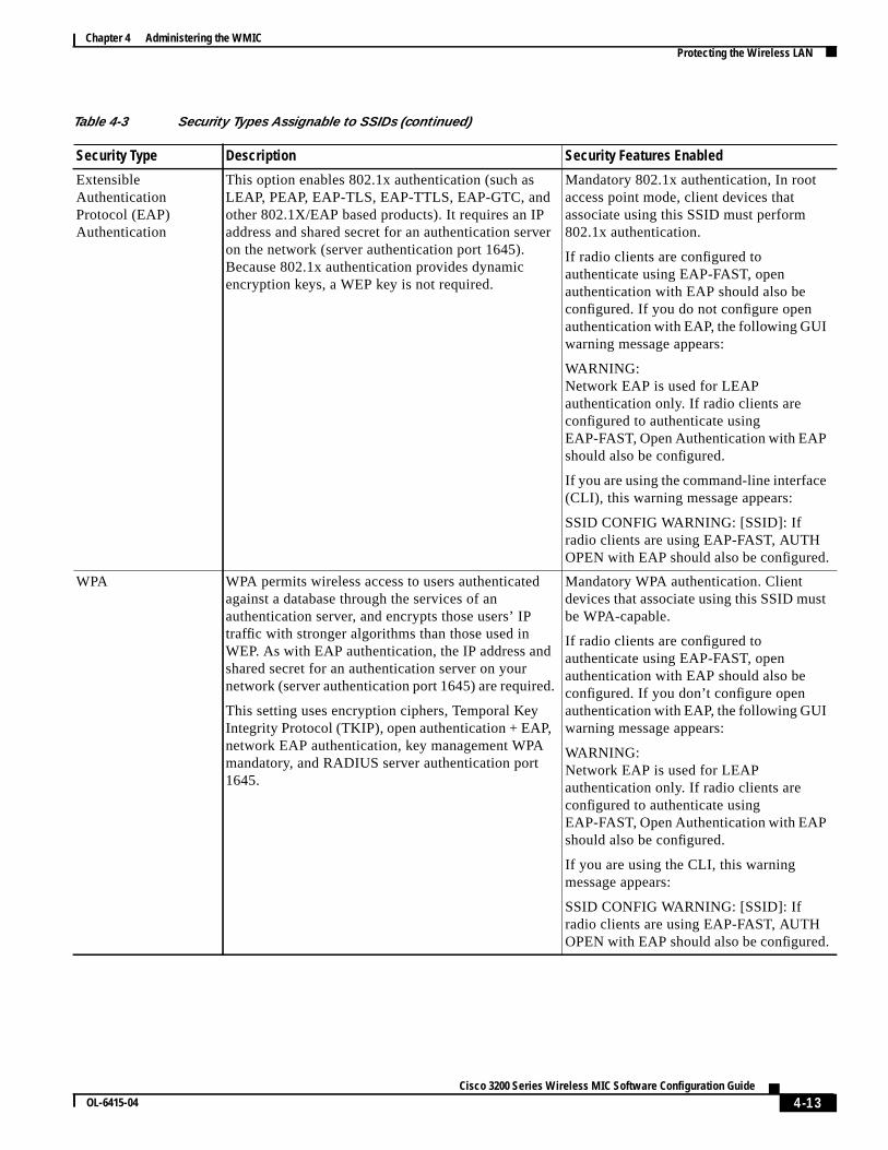
Table 4-3 describes the four security types that you can assign to an SSID.
Table 4-3 Security Types Assignable to SSIDs
Security Type Description Security Features Enabled
No Security This is the least secure option. Use this option only forSSIDs that are used in a public space. Assign thisoption to a VLAN that restricts access to your network.
None.
Static WEP Key This option is more secure than no security. However,static WEP keys are vulnerable to attack. If youconfigure this settings, you should limit association tothe access point based on MAC address, or, if thenetwork does not have a RADIUS server, considerusing an access point as a local authentication server.
Mandatory WEP encryption, no keymanagement, and open authentication. Inroot access point mode, client devicescannot associate using this SSID without aWEP key that matches the access point key.
4-13Cisco 3200 Series Wireless MIC Software Configuration Guide
OL-6415-04
Chapter 4 Administering the WMIC Protecting the Wireless LAN
ExtensibleAuthenticationProtocol (EAP)Authentication
This option enables 802.1x authentication (such asLEAP, PEAP, EAP-TLS, EAP-TTLS, EAP-GTC, andother 802.1X/EAP based products). It requires an IPaddress and shared secret for an authentication serveron the network (server authentication port 1645).Because 802.1x authentication provides dynamicencryption keys, a WEP key is not required.
Mandatory 802.1x authentication, In rootaccess point mode, client devices thatassociate using this SSID must perform802.1x authentication.
If radio clients are configured toauthenticate using EAP-FAST, openauthentication with EAP should also beconfigured. If you do not configure openauthentication with EAP, the following GUIwarning message appears:
WARNING:Network EAP is used for LEAPauthentication only. If radio clients areconfigured to authenticate usingEAP-FAST, Open Authentication with EAPshould also be configured.
If you are using the command-line interface(CLI), this warning message appears:
SSID CONFIG WARNING: [SSID]: Ifradio clients are using EAP-FAST, AUTHOPEN with EAP should also be configured.
WPA WPA permits wireless access to users authenticatedagainst a database through the services of anauthentication server, and encrypts those users’ IPtraffic with stronger algorithms than those used inWEP. As with EAP authentication, the IP address andshared secret for an authentication server on yournetwork (server authentication port 1645) are required.
This setting uses encryption ciphers, Temporal KeyIntegrity Protocol (TKIP), open authentication + EAP,network EAP authentication, key management WPAmandatory, and RADIUS server authentication port1645.
Mandatory WPA authentication. Clientdevices that associate using this SSID mustbe WPA-capable.
If radio clients are configured toauthenticate using EAP-FAST, openauthentication with EAP should also beconfigured. If you don’t configure openauthentication with EAP, the following GUIwarning message appears:
WARNING:Network EAP is used for LEAPauthentication only. If radio clients areconfigured to authenticate usingEAP-FAST, Open Authentication with EAPshould also be configured.
If you are using the CLI, this warningmessage appears:
SSID CONFIG WARNING: [SSID]: Ifradio clients are using EAP-FAST, AUTHOPEN with EAP should also be configured.
Table 4-3 Security Types Assignable to SSIDs (continued)
Security Type Description Security Features Enabled

4-14Cisco 3200 Series Wireless MIC Software Configuration Guide
OL-6415-04
Chapter 4 Administering the WMIC Protecting the Wireless LAN
Security Configuration Examples
This section contains these configuration examples:
• No Security SSID Example
• Static WEP Security Example
• EAP Authentication Security Example
• WPA Security Example
No Security SSID Example
This example shows part of the configuration for creating an SSID calledno_security_ssid, includingthe SSID in the beacon, assigning it to VLAN 10, and selecting VLAN 10 as the native VLAN (as itapplies to the 2.4-GHz ([802.11b/g]) WMIC):
interface Dot11Radio0 no ip address no ip route-cache ! ssid no_security-ssid vlan 10 authentication open guest-mode! concatenation speed basic-1.0 basic-2.0 basic-5.5 6.0 9.0 basic-11.0 12.0 18.0 24.0 36.0 48.0 54.0 rts threshold 4000 station-role root infrastructure-client bridge-group 1!interface Dot11Radio0.10 encapsulation dot1Q 10 no ip route-cache bridge-group 10 bridge-group 10 spanning-disabled!interface FastEthernet0 no ip address no ip route-cache duplex auto speed auto bridge-group 1!interface FastEthernet0.10 encapsulation dot1Q 10 no ip address no ip route-cache duplex auto speed auto bridge-group 1
As it applies to the 4.9-GHz WMIC:
hostname root!username Cisco password 7 02250D480809ip subnet-zero!no aaa new-model!

4-15Cisco 3200 Series Wireless MIC Software Configuration Guide
OL-6415-04
Chapter 4 Administering the WMIC Protecting the Wireless LAN
bridge irb!interface Dot11Radio0 no ip address no ip route-cache ! ssid test authentication open infrastructure-ssid ! spacing 5 channel 4942 speed basic-1.5 2.25 basic-3.0 4.5 basic-6.0 9.0 12.0 13.5 power local 10 station-role root infrastructure-client bridge-group 1 bridge-group 1 spanning-disabled!interface FastEthernet0 no ip address no ip route-cache duplex auto speed auto bridge-group 1 bridge-group 1 spanning-disabled!interface BVI1 ip address 192.1.1.2 255.255.255.0 no ip route-cache!ip http serverno ip http secure-serverip http help-path http://www.cisco.com/warp/public/779/smbiz/prodconfig/help/eagip radius source-interface BVI1logging snmp-trap emergencieslogging snmp-trap alertslogging snmp-trap criticallogging snmp-trap errorslogging snmp-trap warningsbridge 1 route ip!!!line con 0 exec-timeout 0 0 transport preferred all transport output allline vty 0 4 login local transport preferred all transport input all transport output allline vty 5 15 login transport preferred all transport input all transport output all!end
4-16Cisco 3200 Series Wireless MIC Software Configuration Guide
OL-6415-04
Chapter 4 Administering the WMIC Protecting the Wireless LAN
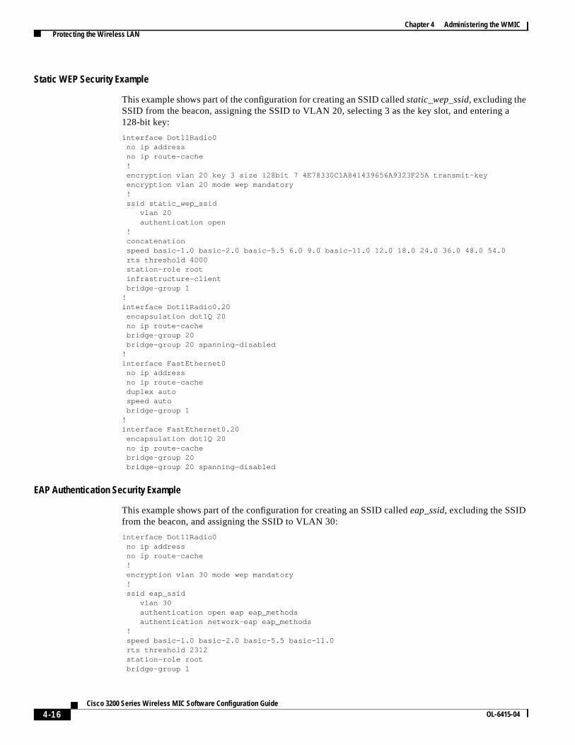
Static WEP Security Example
This example shows part of the configuration for creating an SSID calledstatic_wep_ssid, excluding theSSID from the beacon, assigning the SSID to VLAN 20, selecting 3 as the key slot, and entering a128-bit key:
interface Dot11Radio0 no ip address no ip route-cache ! encryption vlan 20 key 3 size 128bit 7 4E78330C1A841439656A9323F25A transmit-key encryption vlan 20 mode wep mandatory ! ssid static_wep_ssid vlan 20 authentication open ! concatenation speed basic-1.0 basic-2.0 basic-5.5 6.0 9.0 basic-11.0 12.0 18.0 24.0 36.0 48.0 54.0 rts threshold 4000 station-role root infrastructure-client bridge-group 1!interface Dot11Radio0.20 encapsulation dot1Q 20 no ip route-cache bridge-group 20 bridge-group 20 spanning-disabled!interface FastEthernet0 no ip address no ip route-cache duplex auto speed auto bridge-group 1!interface FastEthernet0.20 encapsulation dot1Q 20 no ip route-cache bridge-group 20 bridge-group 20 spanning-disabled
EAP Authentication Security Example
This example shows part of the configuration for creating an SSID calledeap_ssid, excluding the SSIDfrom the beacon, and assigning the SSID to VLAN 30:
interface Dot11Radio0 no ip address no ip route-cache ! encryption vlan 30 mode wep mandatory ! ssid eap_ssid vlan 30 authentication open eap eap_methods authentication network-eap eap_methods ! speed basic-1.0 basic-2.0 basic-5.5 basic-11.0 rts threshold 2312 station-role root bridge-group 1

4-17Cisco 3200 Series Wireless MIC Software Configuration Guide
OL-6415-04
Chapter 4 Administering the WMIC Protecting the Wireless LAN
bridge-group 1 subscriber-loop-control bridge-group 1 block-unknown-source no bridge-group 1 source-learning no bridge-group 1 unicast-flooding bridge-group 1 spanning-disabled!interface Dot11Radio0.30 encapsulation dot1Q 30 no ip route-cache bridge-group 30 bridge-group 30 subscriber-loop-control bridge-group 30 block-unknown-source no bridge-group 30 source-learning no bridge-group 30 unicast-flooding bridge-group 30 spanning-disabled!interface FastEthernet0 mtu 1500 no ip address ip mtu 1564 no ip route-cache duplex auto speed auto bridge-group 1 no bridge-group 1 source-learning bridge-group 1 spanning-disabled!interface FastEthernet0.30 mtu 1500 encapsulation dot1Q 30 no ip route-cache bridge-group 30 no bridge-group 30 source-learning bridge-group 30 spanning-disabled!
WPA Security Example
This example shows part of the configuration for creating an SSID calledwpa_ssid, excluding the SSIDfrom the beacon, and assigning the SSID to VLAN 40:
aaa new-model!aaa group server radius rad_eap server 10.91.104.92 auth-port 1645 acct-port 1646!aaa group server radius rad_mac!aaa group server radius rad_acct!aaa group server radius rad_admin!aaa group server tacacs+ tac_admin!aaa group server radius rad_pmip!aaa group server radius dummy!aaa authentication login eap_methods group rad_eapaaa authentication login mac_methods localaaa authorization exec default localaaa authorization ipmobile default group rad_pmipaaa accounting network acct_methods start-stop group rad_acct

4-18Cisco 3200 Series Wireless MIC Software Configuration Guide
OL-6415-04
Chapter 4 Administering the WMIC Protecting the Wireless LAN
aaa session-id common!!bridge irb!!interface Dot11Radio0 no ip address no ip route-cache ! encryption vlan 40 mode ciphers tkip! ssid wpa_ssid vlan 40 authentication open eap eap_methods authentication network-eap eap_methods authentication key-management wpa! concatenation speed basic-1.0 basic-2.0 basic-5.5 6.0 9.0 basic-11.0 12.0 18.0 24.0 36.0 48 54.0 rts threshold 4000 station-role root infrastructure-client bridge-group 1!interface Dot11Radio0.40 encapsulation dot1Q 40 no ip route-cache bridge-group 40!interface FastEthernet0 no ip address no ip route-cache duplex auto speed auto bridge-group 1!interface FastEthernet0.40 encapsulation dot1Q 40 no ip route-cache bridge-group 40!ip http serverip http help-path http://www.cisco.com/warp/public/779/smbiz/prodconfig/help/eag/122-15.JA/1100ip radius source-interface BVI1radius-server attribute 32 include-in-access-req format%hradius-server host 10.91.104.92 auth-port 1645 acct-port 1646 key 7 135445415F59radius-server authorization permit missing Service-Typeradius-server vsa send accountingbridge 1 route ip!line con 0line vty 5 15!end

4-19Cisco 3200 Series Wireless MIC Software Configuration Guide
OL-6415-04
Chapter 4 Administering the WMIC Configuring and Enabling RADIUS
Configuring and Enabling RADIUSThis section describes how to configure and enable Remote Authentication Dial-In User Service(RADIUS).
Understanding RADIUSRADIUS is a distributed client/server system that secures networks against unauthorized access.RADIUS clients run on supported Cisco devices and send authentication requests to a central RADIUSserver that contains all user authentication and network service access information. The RADIUS hostis normally a multiuser system running RADIUS server software from Cisco, Livingston, Merit,Microsoft, or another software provider. For more information, see the RADIUS server documentation.
Use RADIUS in these network environments:
• Networks with multiple-vendor access servers, each supporting RADIUS. For example, accessservers from several vendors use a single RADIUS server-based security database. In an IP-basednetwork with multiple vendors’ access servers, dial-in users are authenticated through a RADIUSserver that is customized to work with the Kerberos security system.
• Turnkey network security environments in which applications support the RADIUS protocol, suchas an access environment that uses asmart card access control system. In one case, RADIUS hasbeen used with Enigma’s security cards to validate users and to grant access to network resources.
• Networks already using RADIUS. You can add a Cisco bridge containing a RADIUS client to thenetwork.
• Networks that require resource accounting. You can use RADIUS accounting independent ofRADIUS authentication or authorization. The RADIUS accounting functions allow data to be sentat the start and end of services, showing the amount of resources (such as time, packets, bytes, andso forth) used during the session. An Internet service provider might use a freeware-based versionof RADIUS access control and accounting software to meet special security and billing needs.
RADIUS is not suitable for these network situations:
• Multiprotocol access environments. RADIUS does not support AppleTalk Remote Access (ARA),NetBIOS Frame Control Protocol (NBFCP), NetWare Asynchronous Services Interface (NASI), orX.25 Packet Assembler Disassembler (PAD) connections.
• Switch-to-switch or router-to-router situations. RADIUS does not provide two-way authentication.RADIUS can be used to authenticate from one device to a non-Cisco device if the non-Cisco devicerequires authentication.
• Networks using a variety of services. RADIUS generally binds a user to one service model.
4-20Cisco 3200 Series Wireless MIC Software Configuration Guide
OL-6415-04
Chapter 4 Administering the WMIC Configuring and Enabling RADIUS
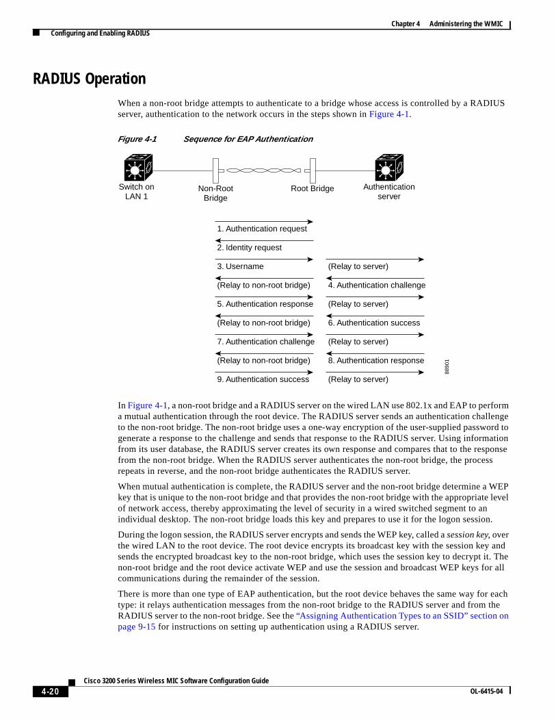
RADIUS OperationWhen a non-root bridge attempts to authenticate to a bridge whose access is controlled by a RADIUSserver, authentication to the network occurs in the steps shown inFigure 4-1.
Figure 4-1 Sequence for EAP Authentication
In Figure 4-1, a non-root bridge and a RADIUS server on the wired LAN use 802.1x and EAP to performa mutual authentication through the root device. The RADIUS server sends an authentication challengeto the non-root bridge. The non-root bridge uses a one-way encryption of the user-supplied password togenerate a response to the challenge and sends that response to the RADIUS server. Using informationfrom its user database, the RADIUS server creates its own response and compares that to the responsefrom the non-root bridge. When the RADIUS server authenticates the non-root bridge, the processrepeats in reverse, and the non-root bridge authenticates the RADIUS server.
When mutual authentication is complete, the RADIUS server and the non-root bridge determine a WEPkey that is unique to the non-root bridge and that provides the non-root bridge with the appropriate levelof network access, thereby approximating the level of security in a wired switched segment to anindividual desktop. The non-root bridge loads this key and prepares to use it for the logon session.
During the logon session, the RADIUS server encrypts and sends the WEP key, called asession key, overthe wired LAN to the root device. The root device encrypts its broadcast key with the session key andsends the encrypted broadcast key to the non-root bridge, which uses the session key to decrypt it. Thenon-root bridge and the root device activate WEP and use the session and broadcast WEP keys for allcommunications during the remainder of the session.
There is more than one type of EAP authentication, but the root device behaves the same way for eachtype: it relays authentication messages from the non-root bridge to the RADIUS server and from theRADIUS server to the non-root bridge. See the“Assigning Authentication Types to an SSID” section onpage 9-15 for instructions on setting up authentication using a RADIUS server.
8890
1
Switch onLAN 1
1. Authentication request
Authenticationserver
Non-RootBridge
Root Bridge
2. Identity request
3. Username
(Relay to non-root bridge)
5. Authentication response
(Relay to non-root bridge)
7. Authentication challenge
(Relay to non-root bridge)
9. Authentication success
(Relay to server)
4. Authentication challenge
(Relay to server)
6. Authentication success
(Relay to server)
8. Authentication response
(Relay to server)

4-21Cisco 3200 Series Wireless MIC Software Configuration Guide
OL-6415-04
Chapter 4 Administering the WMIC Configuring and Enabling RADIUS
Controlling WMIC Access with RADIUSThis section describes how to control administrator access to the WMIC using RADIUS.
RADIUS provides detailed accounting information and flexible administrative control overauthentication and authorization processes. RADIUS is facilitated through AAA and can be enabled onlythrough authentication, authorization, and accounting (AAA) commands. RADIUS and AAA aredisabled by default.
At a minimum, the host or hosts that run the RADIUS server software must be identified and the methodlists for RADIUS authentication must be defined. Optionally, method lists for RADIUS authorizationand accounting can be defined.
A method list defines the sequence and methods to be used to authenticate, to authorize, or to keepaccounts on a non-root bridge. Method lists are used to designate one or more security protocols to beused, thus ensuring a backup system if the initial method fails. The software uses the first method listedto authenticate, to authorize, or to keep accounts on non-root bridges; if that method does not respond,the software selects the next method in the list. This process continues until there is successfulcommunication with a listed method or the method list is exhausted.
You must have access to and should configure a RADIUS server before you configure RADIUS features.
These sections describe RADIUS configuration:
• Identifying the RADIUS Server Host
• Configuring RADIUS Login Authentication
• Defining AAA Server Groups
• Configuring RADIUS Authorization for User Privileged Access and Network Services
• Starting RADIUS Accounting
• Configuring Settings for All RADIUS Servers
• Configuring the Bridge to Use Vendor-Specific RADIUS Attributes
• Configuring the Bridge for Vendor-Proprietary RADIUS Server Communication
• Displaying the RADIUS Configuration
Note For complete syntax and usage information for the commands used in this section, see theCisco IOSSecurity Command Reference for Release 12.2.
Identifying the RADIUS Server Host
Access point-to-RADIUS-server communication involves several components:
• Hostname or IP address
• Authentication destination port
• Accounting destination port
• Key string
• Timeout period
• Retransmission value

4-22Cisco 3200 Series Wireless MIC Software Configuration Guide
OL-6415-04
Chapter 4 Administering the WMIC Configuring and Enabling RADIUS
RADIUS security servers are identified by their hostname or IP address, hostname and specific UserDatagram Protocol (UDP) port numbers, or IP address and specific UDP port numbers. The combinationof the IP address and the UDP port number creates a unique identifier allowing different ports to beindividually defined as RADIUS hosts providing a specific AAA service. This unique identifier enablesRADIUS requests to be sent to multiple UDP ports on a server at the same IP address.
If two different host entries on the same RADIUS server are configured for the same service—such asaccounting—the second host entry configured acts as a failover backup to the first one. Using thisexample, if the first host entry fails to provide accounting services, the bridge tries the second host entryconfigured on the same device for accounting services. (The RADIUS host entries are tried in the orderthat they are configured.)
A RADIUS server and the bridge use a shared secret text string to encrypt passwords and exchangeresponses. To configure RADIUS to use the AAA security commands, you must specify the host that isrunning the RADIUS server daemon and a secret text (key) string that it shares with the bridge.
The timeout, retransmission, and encryption key values can be configured globally per server for allRADIUS servers or in some combination of global and per-server settings. To apply these settingsglobally to all RADIUS servers communicating with the bridge, use the three unique globalconfiguration commands:radius-server timeout, radius-server retransmit, andradius-server key. Toapply these values on a specific RADIUS server, use theradius-server hostcommand in globalconfiguration mode.
Note If you configure both global and per-server functions (timeout, retransmission, and key commands) onthe bridge, the per-server timer, retransmission, and key value commands override global timer,retransmission, and key value commands. For information on configuring these setting on all RADIUSservers, see the“Configuring Settings for All RADIUS Servers” section on page 4-28.
You can configure the bridge to use AAA server groups to group existing server hosts for authentication.For more information, see the“Defining AAA Server Groups” section on page 4-25.
To configure per-server RADIUS server communication, follow these required steps, beginning inprivileged EXEC mode:
Command Purpose
Step 1 configure terminal Enters global configuration mode.
Step 2 aaa new-model Enables AAA.
4-23Cisco 3200 Series Wireless MIC Software Configuration Guide
OL-6415-04
Chapter 4 Administering the WMIC Configuring and Enabling RADIUS
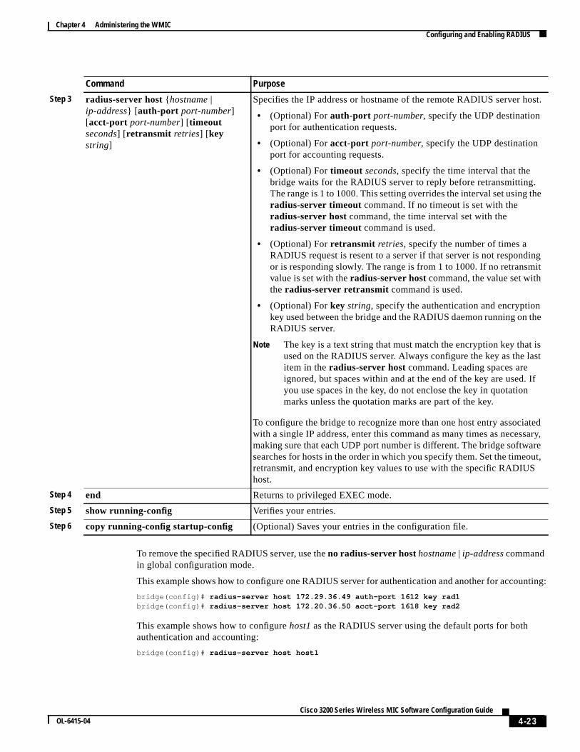
To remove the specified RADIUS server, use theno radius-server hosthostname| ip-addresscommandin global configuration mode.
This example shows how to configure one RADIUS server for authentication and another for accounting:
bridge(config)# radius-server host 172.29.36.49 auth-port 1612 key rad1bridge(config)# radius-server host 172.20.36.50 acct-port 1618 key rad2
This example shows how to configurehost1 as the RADIUS server using the default ports for bothauthentication and accounting:
bridge(config)# radius-server host host1
Step 3 radius-server host {hostname |ip-address} [ auth-port port-number][acct-port port-number] [ timeoutseconds] [ retransmit retries] [keystring]
Specifies the IP address or hostname of the remote RADIUS server host.
• (Optional) Forauth-port port-number, specify the UDP destinationport for authentication requests.
• (Optional) Foracct-port port-number, specify the UDP destinationport for accounting requests.
• (Optional) Fortimeout seconds, specify the time interval that thebridge waits for the RADIUS server to reply before retransmitting.The range is 1 to 1000. This setting overrides the interval set using theradius-server timeout command. If no timeout is set with theradius-server host command, the time interval set with theradius-server timeout command is used.
• (Optional) Forretransmit retries, specify the number of times aRADIUS request is resent to a server if that server is not respondingor is responding slowly. The range is from 1 to 1000. If no retransmitvalue is set with theradius-server hostcommand, the value set withthe radius-server retransmit command is used.
• (Optional) Forkey string, specify the authentication and encryptionkey used between the bridge and the RADIUS daemon running on theRADIUS server.
Note The key is a text string that must match the encryption key that isused on the RADIUS server. Always configure the key as the lastitem in theradius-server hostcommand. Leading spaces areignored, but spaces within and at the end of the key are used. Ifyou use spaces in the key, do not enclose the key in quotationmarks unless the quotation marks are part of the key.
To configure the bridge to recognize more than one host entry associatedwith a single IP address, enter this command as many times as necessary,making sure that each UDP port number is different. The bridge softwaresearches for hosts in the order in which you specify them. Set the timeout,retransmit, and encryption key values to use with the specific RADIUShost.
Step 4 end Returns to privileged EXEC mode.
Step 5 show running-config Verifies your entries.
Step 6 copy running-config startup-config (Optional) Saves your entries in the configuration file.
Command Purpose
4-24Cisco 3200 Series Wireless MIC Software Configuration Guide
OL-6415-04
Chapter 4 Administering the WMIC Configuring and Enabling RADIUS
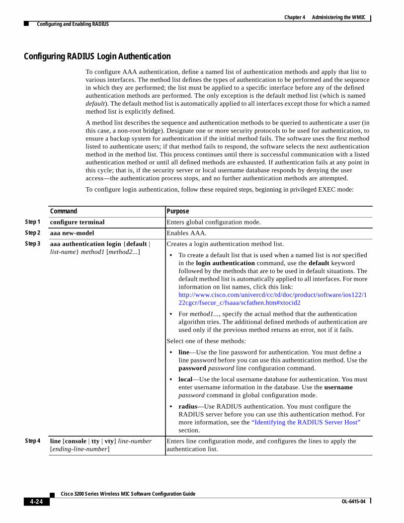
Configuring RADIUS Login Authentication
To configure AAA authentication, define a named list of authentication methods and apply that list tovarious interfaces. The method list defines the types of authentication to be performed and the sequencein which they are performed; the list must be applied to a specific interface before any of the definedauthentication methods are performed. The only exception is the default method list (which is nameddefault). The default method list is automatically applied to all interfaces except those for which a namedmethod list is explicitly defined.
A method list describes the sequence and authentication methods to be queried to authenticate a user (inthis case, a non-root bridge). Designate one or more security protocols to be used for authentication, toensure a backup system for authentication if the initial method fails. The software uses the first methodlisted to authenticate users; if that method fails to respond, the software selects the next authenticationmethod in the method list. This process continues until there is successful communication with a listedauthentication method or until all defined methods are exhausted. If authentication fails at any point inthis cycle; that is, if the security server or local username database responds by denying the useraccess—the authentication process stops, and no further authentication methods are attempted.
To configure login authentication, follow these required steps, beginning in privileged EXEC mode:
Command Purpose
Step 1 configure terminal Enters global configuration mode.
Step 2 aaa new-model Enables AAA.
Step 3 aaa authentication login {default |list-name} method1 [method2...]
Creates a login authentication method list.
• To create a default list that is used when a named list isnot specifiedin the login authentication command, use thedefault keywordfollowed by the methods that are to be used in default situations. Thedefault method list is automatically applied to all interfaces. For moreinformation on list names, click this link:http://www.cisco.com/univercd/cc/td/doc/product/software/ios122/122cgcr/fsecur_c/fsaaa/scfathen.htm#xtocid2
• For method1..., specify the actual method that the authenticationalgorithm tries. The additional defined methods of authentication areused only if the previous method returns an error, not if it fails.
Select one of these methods:
• line—Use the line password for authentication. You must define aline password before you can use this authentication method. Use thepasswordpassword line configuration command.
• local—Use the local username database for authentication. You mustenter username information in the database. Use theusernamepassword command in global configuration mode.
• radius—Use RADIUS authentication. You must configure theRADIUS server before you can use this authentication method. Formore information, see the“Identifying the RADIUS Server Host”section.
Step 4 line [console | tty | vty] line-number[ending-line-number]
Enters line configuration mode, and configures the lines to apply theauthentication list.

4-25Cisco 3200 Series Wireless MIC Software Configuration Guide
OL-6415-04
Chapter 4 Administering the WMIC Configuring and Enabling RADIUS
To disable AAA, use theno aaa new-model command in global configuration mode. To disable AAAauthentication, use the no aaa authentication login {default | list-name} method1 [method2...]command in global configuration mode. To disable RADIUS authentication for logins or to return to thedefault value, use theno login authentication { default | list-name} command in line configurationmode.
Defining AAA Server Groups
Configure the bridge to use AAA server groups to group existing server hosts for authentication. Selecta subset of the configured server hosts, and use them for a particular service. The server group is usedwith a global server-host list, which lists the IP addresses of the selected server hosts.
Server groups also can include multiple host entries for the same server if each entry has a uniqueidentifier (the combination of the IP address and UDP port number), allowing different ports to beindividually defined as RADIUS hosts providing a specific AAA service. If you configure two differenthost entries on the same RADIUS server for the same service (such as accounting), the secondconfigured host entry acts as a failover backup to the first one.
Use theservergroup server configuration command to associate a particular server with a defined groupserver. To identify the server by its IP address or to identify multiple host instances or entries, use theoptionalauth-port andacct-port keywords.
To define the AAA server group and associate a particular RADIUS server with it, follow these steps,beginning in privileged EXEC mode:
Step 5 login authentication {default |list-name}
Applies the authentication list to a line or set of lines.
• If you specifydefault, use the default list created with theaaaauthentication login command.
• For list-name, specify the list created with theaaa authenticationlogin command.
Step 6 radius-server attribute 32include-in-access-req format %h
Configures the device to send its system name in the NAS_ID attribute forauthentication.
Step 7 end Returns to privileged EXEC mode.
Step 8 show running-config Verifies your entries.
Step 9 copy running-config startup-config (Optional) Saves your entries in the configuration file.
Command Purpose
Command Purpose
Step 1 configure terminal Enters global configuration mode.
Step 2 aaa new-model Enables AAA.

4-26Cisco 3200 Series Wireless MIC Software Configuration Guide
OL-6415-04
Chapter 4 Administering the WMIC Configuring and Enabling RADIUS
To remove the specified RADIUS server, use theno radius-server hosthostname| ip-addresscommandin global configuration mode. To remove a server group from the configuration list, use theno aaa groupserver radius group-name command in global configuration mode. To remove the IP address of aRADIUS server, use theno server ip-address command in server group configuration mode.
Step 3 radius-server host{ hostname| ip-address} [ auth-portport-number] [acct-portport-number] [ timeoutseconds] [ retransmit retries][key string]
Specifies the IP address or hostname of the remote RADIUS server host.
• (Optional) Forauth-port port-number, specify the UDP destination port forauthentication requests.
• (Optional) Foracct-port port-number, specify the UDP destination port foraccounting requests.
• (Optional) Fortimeout seconds, specify the time interval that the bridge waits forthe RADIUS server to reply before retransmitting. The range is 1 to 1000. Thissetting overrides the interval set using theradius-server timeoutcommand. If notimeout is set with theradius-server host command, the time interval set withthe radius-server timeout command is used.
• (Optional) Forretransmit retries, specify the number of times a RADIUSrequest is resent to a server if that server is not responding or is respondingslowly. The range is from 1 to 1000. If no retransmit value is set with theradius-server host command, the value set with theradius-server retransmitcommand is used.
• (Optional) Forkey string, specify the authentication and encryption key usedbetween the bridge and the RADIUS daemon running on the RADIUS server.
Note The key is a text string that must match the encryption key that is used on theRADIUS server. Always configure the key as the last item in theradius-server hostcommand. Leading spaces are ignored, but spaces withinand at the end of the key are used. If you use spaces in the key, do not enclosethe key in quotation marks unless the quotation marks are part of the key.
To configure the bridge to recognize more than one host entry associated with a singleIP address, enter this command as many times as necessary, making sure that eachUDP port number is different. The bridge software searches for hosts in the order inwhich you specify them. Set the timeout, retransmit, and encryption key values to usewith the specific RADIUS host.
Step 4 aaa group server radiusgroup-name
Defines the AAA server-group with a group name.
This command puts the bridge in a server group configuration mode.
Step 5 server ip-address Associates a particular RADIUS server with the defined server group. Repeat this stepfor each RADIUS server in the AAA server group.
Note Each server in the group must be previously defined in Step 2.
Step 6 end Returns to privileged EXEC mode.
Step 7 show running-config Verifies your entries.
Step 8 copy running-configstartup-config
(Optional) Saves your entries in the configuration file.
Step 9 Enables RADIUS login authentication. See the“Configuring RADIUS LoginAuthentication” section on page 4-24.
Command Purpose

4-27Cisco 3200 Series Wireless MIC Software Configuration Guide
OL-6415-04
Chapter 4 Administering the WMIC Configuring and Enabling RADIUS
In this example, the bridge is configured to recognize two different RADIUS group servers (group1andgroup2). Group1 has two different host entries on the same RADIUS server configured for the sameservices. The second host entry acts as a failover backup to the first entry.
bridge(config)# aaa new-modelbridge(config)# radius-server host 172.20.0.1 auth-port 1000 acct-port 1001bridge(config)# radius-server host 172.10.0.1 auth-port 1645 acct-port 1646bridge(config)# aaa group server radius group1bridge(config-sg-radius)# server 172.20.0.1 auth-port 1000 acct-port 1001bridge(config-sg-radius)# exitbridge(config)# aaa group server radius group2bridge(config-sg-radius)# server 172.20.0.1 auth-port 2000 acct-port 2001bridge(config-sg-radius)# exit
Configuring RADIUS Authorization for User Privileged Access and Network Services
AAA authorization limits the services available to a user. When AAA authorization is enabled, thebridge uses information retrieved from the user profile, which is in the local user database or on thesecurity server, to configure the user’s session. The user is granted access to a requested service only ifthe information in the user profile allows it.
You can use theaaa authorization command in global configuration mode with theradius keyword toset parameters that restrict a user’s network access to privileged EXEC mode.
The aaa authorization exec radius localcommand sets these authorization parameters:
• Use RADIUS for privileged EXEC access authorization if authentication was performed by usingRADIUS.
• Use the local database if authentication was not performed by using RADIUS.
Note Authorization is bypassed for authenticated users who log in through the CLI even if authorization hasbeen configured.
To specify RADIUS authorization for privileged EXEC access and network services,follow these steps,beginning in privileged EXEC mode:
To disable authorization, use theno aaa authorization {network | exec} method1 command in globalconfiguration mode.
Command Purpose
Step 1 configure terminal Enters global configuration mode.
Step 2 aaa authorization network radius Configures the bridge for user RADIUS authorization for allnetwork-related service requests.
Step 3 aaa authorization exec radius Configures the bridge for user RADIUS authorization and determines ifthe user has privileged EXEC access.
Theexec keyword might return user profile information (such asautocommand information).
Step 4 end Returns to privileged EXEC mode.
Step 5 show running-config Verifies your entries.
Step 6 copy running-config startup-config (Optional) Saves your entries in the configuration file.

4-28Cisco 3200 Series Wireless MIC Software Configuration Guide
OL-6415-04
Chapter 4 Administering the WMIC Configuring and Enabling RADIUS
Starting RADIUS Accounting
The AAA accounting feature tracks the services that users are accessing and the amount of networkresources that they are consuming. When AAA accounting is enabled, the bridge reports user activity tothe RADIUS security server in the form of accounting records. Each accounting record containsaccounting attribute-value (AV) pairs and is stored on the security server. This data can then be analyzedfor network management, client billing, or auditing.
To enable RADIUS accounting for each Cisco IOS privilege level and for network services,follow thesesteps, beginning in privileged EXEC mode:
To disable accounting, use theno aaa accounting{ network | exec} { start-stop} method1...commandin global configuration mode.
Configuring Settings for All RADIUS Servers
To configure global communication settings between the bridge and all RADIUS servers, follow thesesteps, beginning in privileged EXEC mode:
Command Purpose
Step 1 configure terminal Enters global configuration mode.
Step 2 aaa accounting network start-stopradius
Enables RADIUS accounting for all network-related service requests.
Step 3 ip radius source-interface bvi1 Configures the bridge to send its Bridge-Group Virtual Interface (BVI)IP address in the NAS_IP_ADDRESS attribute for accounting records.
Step 4 aaa accounting update periodicminutes Enters an accounting update interval in minutes.
Step 5 end Returns to privileged EXEC mode.
Step 6 show running-config Verifies your entries.
Step 7 copy running-config startup-config (Optional) Saves your entries in the configuration file.
Command Purpose
Step 1 configure terminal Enters global configuration mode.
Step 2 radius-server keystring Specifies the shared secret text string to be used between the bridge and allRADIUS servers.
Note The key is a text string that must match the encryption key that isused on the RADIUS server. Leading spaces are ignored, but spaceswithin and at the end of the key are used. If you use spaces in yourkey, do not enclose the key in quotation marks unless the quotationmarks are part of the key.
Step 3 radius-server retransmit retries Specifies the number of times that the bridge sends each RADIUS requestto the server before giving up. The default is 3; the range 1 to 1000.
Step 4 radius-server timeout seconds Specifies the number of seconds that a bridge waits for a reply to a RADIUSrequest before resending the request. The default is 5; the range is from 1to 1000.

4-29Cisco 3200 Series Wireless MIC Software Configuration Guide
OL-6415-04
Chapter 4 Administering the WMIC Configuring and Enabling RADIUS
To return to the default setting for the retransmit, timeout, and deadtime, use theno forms of thesecommands.
Configuring the Bridge to Use Vendor-Specific RADIUS Attributes
The Internet Engineering Task Force (IETF) draft standard specifies a method for communicatingvendor-specific information between the bridge and the RADIUS server by using the vendor-specificattribute (attribute 26). Vendor-specific attributes (VSAs) allow vendors to support their own extendedattributes that are not suitable for general use. The Cisco RADIUS implementation supports onevendor-specific option by using the format recommended in the specification. Cisco’s vendor ID is 9,and the supported option has vendor type 1, which is namedcisco-avpair. The value is a string with thisformat:
protocol : attribute sep value *
Protocol is a value of the Cisco protocol attribute for a particular type of authorization.Attribute andvalue are an appropriate AV pair defined in the Cisco TACACS+ specification, andsep is = formandatory attributes and the asterisk (*) for optional attributes. This allows the full set of featuresavailable for TACACS+ authorization to also be used for RADIUS.
For example, the following AV pair activates Cisco’smultiple named ip address poolsfeature during IPauthorization (during Point-to-Point Protocol IP Control Protocol (PPP IPCP) address assignment):
cisco-avpair= ”ip:addr-pool=first“
The following example shows how to provide a user logging in from a bridge with immediate access toprivileged EXEC commands:
cisco-avpair= ”shell:priv-lvl=15“
Other vendors have their own unique vendor IDs, options, and associated VSAs. For more informationabout vendor IDs and VSAs, see RFC 2138, “Remote Authentication Dial-In User Service (RADIUS).”
Step 5 radius-server deadtimeminutes Use this command to cause the Cisco IOS software to mark as “dead” anyRADIUS servers that fail to respond to authentication requests, thusavoiding the wait for the request to time out before trying the nextconfigured server. A RADIUS server marked as dead is skipped byadditional requests for the duration of minutes that you specify.
Note If you set up more than one RADIUS server, you must configure theRADIUS server deadtime for optimal performance.
Step 6 radius-server attribute 32include-in-access-req format %h
Configures the bridge to send its system name in the NAS_ID attribute forauthentication.
Step 7 end Returns to privileged EXEC mode.
Step 8 show running-config Verifies your settings.
Step 9 copy running-config startup-config (Optional) Saves your entries in the configuration file.
Command Purpose

4-30Cisco 3200 Series Wireless MIC Software Configuration Guide
OL-6415-04
Chapter 4 Administering the WMIC Configuring and Enabling RADIUS
To configure the bridge to recognize and use VSAs, follow these steps, beginning in privileged EXECmode:
For a complete list of RADIUS attributes or more information about VSA 26, see the “RADIUSAttributes” appendix in theCisco IOS Security Configuration Guide for Release 12.2.
Configuring the Bridge for Vendor-Proprietary RADIUS Server Communication
Although an IETF draft standard for RADIUS specifies a method for communicating vendor-proprietaryinformation between the bridge and the RADIUS server, some vendors have extended the RADIUSattribute set in a unique way. Cisco IOS software supports a subset of vendor-proprietary RADIUSattributes.
As mentioned earlier, to configure RADIUS (whether vendor-proprietary or IETF draft-compliant), youmust specify the host that is running the RADIUS server daemon and the secret text string that it shareswith the bridge. You specify the RADIUS host and secret text string by using theradius-servercommand in global configuration mode.
To specify a vendor-proprietary RADIUS server host and a shared secret text string, follow these steps,beginning in privileged EXEC mode:
Command Purpose
Step 1 configure terminal Enters global configuration mode.
Step 2 radius-server vsa send [accounting |authentication]
Enables the bridge to recognize and use VSAs as defined by RADIUS IETFattribute 26.
• (Optional) Use theaccounting keyword to limit the set of recognizedVSAs to only accounting attributes.
• (Optional) Use theauthentication keyword to limit the set ofrecognized VSAs to only authentication attributes.
If you enter this command without keywords, both accounting andauthentication VSAs are used.
Step 3 end Returns to privileged EXEC mode.
Step 4 show running-config Verifies your settings.
Step 5 copy running-config startup-config (Optional) Saves your entries in the configuration file.
Command Purpose
Step 1 configure terminal Enters global configuration mode.
Step 2 radius-server host { hostname | ip-address} non-standard Specifies the IP address or hostname of the remoteRADIUS server host and identify that it is using avendor-proprietary implementation of RADIUS.

4-31Cisco 3200 Series Wireless MIC Software Configuration Guide
OL-6415-04
Chapter 4 Administering the WMIC Configuring and Enabling RADIUS
To delete the vendor-proprietary RADIUS host, use theno radius-server host{ hostname| ip-address}non-standardcommand in global configuration mode. To disable the key, use theno radius-server keycommand in global configuration mode.
This example shows how to specify a vendor-proprietary RADIUS host and a secret key ofrad124between the bridge and the server:
bridge(config)# radius-server host 172.20.30.15 nonstandardbridge(config)# radius-server key rad124
Displaying the RADIUS Configuration
To display the RADIUS configuration, use theshow running-config command.in privileged EXECmode:
Step 3 radius-server keystring Specifies the shared secret text string used betweenthe bridge and the vendor-proprietary RADIUSserver. The bridge and the RADIUS server use thistext string to encrypt passwords and exchangeresponses.
Note The key is a text string that must match theencryption key that is used on the RADIUSserver. Leading spaces are ignored, but spaceswithin and at the end of the key are used. Ifyou use spaces in the key, do not enclose thekey in quotation marks unless the quotationmarks are part of the key.
Step 4 end Returns to privileged EXEC mode.
Step 5 show running-config Verifies your settings.
Step 6 copy running-config startup-config (Optional) Saves your entries in the configurationfile.
Command Purpose
4-32Cisco 3200 Series Wireless MIC Software Configuration Guide
OL-6415-04
Chapter 4 Administering the WMIC Controlling WMIC Access with TACACS+
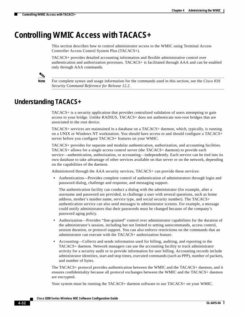
Controlling WMIC Access with TACACS+This section describes how to control administrator access to the WMIC using Terminal AccessController Access Control System Plus (TACACS+).
TACACS+ provides detailed accounting information and flexible administrative control overauthentication and authorization processes. TACACS+ is facilitated through AAA and can be enabledonly through AAA commands.
Note For complete syntax and usage information for the commands used in this section, see theCisco IOSSecurity Command Reference for Release 12.2.
Understanding TACACS+TACACS+ is a security application that provides centralized validation of users attempting to gainaccess to your bridge. Unlike RADIUS, TACACS+ does not authenticate non-root bridges that areassociated to the root device.
TACACS+ services are maintained in a database on a TACACS+ daemon, which, typically, is runningon a UNIX or Windows NT workstation. You should have access to and should configure a TACACS+server before you configure TACACS+ features on your WMIC.
TACACS+ provides for separate and modular authentication, authorization, and accounting facilities.TACACS+ allows for a single access control server (the TACACS+ daemon) to provide eachservice—authentication, authorization, or accounting—independently. Each service can be tied into itsown database to take advantage of other services available on that server or on the network, dependingon the capabilities of the daemon.
Administered through the AAA security services, TACACS+ can provide these services:
• Authentication—Provides complete control of authentication of administrators through login andpassword dialog, challenge and response, and messaging support.
The authentication facility can conduct a dialog with the administrator (for example, after ausername and password are provided, to challenge a user with several questions, such as homeaddress, mother’s maiden name, service type, and social security number). The TACACS+authentication service can also send messages to administrator screens. For example, a messagecould notify administrators that their passwords must be changed because of the company’spassword aging policy.
• Authorization—Provides “fine-grained” control over administrator capabilities for the duration ofthe administrator’s session, including but not limited to setting autocommands, access control,session duration, or protocol support. You can also enforce restrictions on the commands that anadministrator can execute with the TACACS+ authorization feature.
• Accounting—Collects and sends information used for billing, auditing, and reporting to theTACACS+ daemon. Network managers can use the accounting facility to track administratoractivity for a security audit or to provide information for user billing. Accounting records includeadministrator identities, start and stop times, executed commands (such as PPP), number of packets,and number of bytes.
The TACACS+ protocol provides authentication between the WMIC and the TACACS+ daemon, and itensures confidentiality because all protocol exchanges between the WMIC and the TACACS+ daemonare encrypted.
Your system must be running the TACACS+ daemon software to use TACACS+ on your WMIC.

4-33Cisco 3200 Series Wireless MIC Software Configuration Guide
OL-6415-04
Chapter 4 Administering the WMIC Controlling WMIC Access with TACACS+
TACACS+ OperationWhen an administrator attempts a simple ASCII login by authenticating to a WMIC using TACACS+,this process occurs:
1. When the connection is established, the WMIC contacts the TACACS+ daemon to obtain a usernameprompt, which is then displayed to the administrator. The administrator enters a username; theWMIC then contacts the TACACS+ daemon to obtain a password prompt. The WMIC displays thepassword prompt to the administrator, the administrator enters a password, and the password is thensent to the TACACS+ daemon.
TACACS+ allows a conversation between the daemon and the administrator until the daemonreceives enough information to authenticate the administrator. The daemon prompts for a usernameand password combination, but can include other items, such as the user’s mother’s maiden name.
2. The WMIC eventually receives one of these responses from the TACACS+ daemon:
– ACCEPT—The administrator is authenticated, and service can begin. If the WMIC isconfigured to require authorization, authorization begins at this time.
– REJECT—The administrator is not authenticated. The administrator can be denied access or isprompted to retry the login sequence, depending on the TACACS+ daemon.
– ERROR—An error occurred at some time during authentication with the daemon or in thenetwork connection between the daemon and the WMIC. If an ERROR response is received, theWMIC typically tries to use an alternative method for authenticating the administrator.
– CONTINUE—The administrator is prompted for additional authentication information.
After authentication, the administrator attempts authorization if authorization has been enabled onthe WMIC. Administrators must successfully complete TACACS+ authentication before proceedingto TACACS+ authorization.
3. If TACACS+ authorization is required, the TACACS+ daemon is again contacted, and it returns anACCEPT or REJECT authorization response. If an ACCEPT response is returned, the responsecontains data in the form of attributes that direct the EXEC or NETWORK session for thatadministrator, determining the services that the administrator can access:
– Telnet, rlogin, or privileged EXEC services
– Connection parameters, including the host or client IP address, access list, and administratortimeouts
Default TACACS+ ConfigurationTACACS+ and AAA are disabled by default.
To prevent a lapse in security, you cannot configure TACACS+ through a network managementapplication.When enabled, TACACS+ can authenticate administrators accessing the WMIC through theCLI.

4-34Cisco 3200 Series Wireless MIC Software Configuration Guide
OL-6415-04
Chapter 4 Administering the WMIC Controlling WMIC Access with TACACS+
Configuring TACACS+ Login AuthenticationTo configure AAA authentication, you define a named list of authentication methods and then apply thatlist to various interfaces. The method list defines the types of authentication to be performed and thesequence in which they are performed; the list must be applied to a specific interface before any of thedefined authentication methods are performed. The only exception is the default method list (which isnameddefault).
The default method list is automatically applied to all interfaces except those for which a named methodlist is explicitly defined. A defined method list overrides the default method list.
A method list describes the sequence and authentication methods to be queried to authenticate a user.You can designate one or more security protocols to be used for authentication, to ensure a backupsystem for authentication if the initial method fails. The software uses the first method listed toauthenticate users; if that method fails, the software selects the next authentication method in the methodlist. This process continues until there is successful communication with a listed authentication methodor until all defined methods are exhausted. If authentication fails—that is, the security server or localusername database responds by denying the user access— the authentication process stops, and nofurther authentication methods are attempted.
Identifying the TACACS+ Server Host and Setting the Authentication Key
You can configure the WMIC to use a single server or to use AAA server groups to group existing serverhosts for authentication. You can group servers to select a subset of the configured server hosts and usethem for a particular service. The server group is used with a global server-host list and contains the listof IP addresses of the selected server hosts.
To identify the IP host or host maintaining TACACS+ server and optionally set the encryption key,followthese steps, beginning in privileged EXEC mode:
Command Purpose
Step 1 configure terminal Enters global configuration mode.
Step 2 tacacs-server hosthostname [portinteger] [ timeout integer] [key string]
Identifies the IP host or hosts maintaining a TACACS+ server. Enter thiscommand multiple times to create a list of preferred hosts. The softwaresearches for hosts in the order in which you specify them.
• For hostname, specify the name or IP address of the host.
• (Optional) Forport integer, specify a server port number. The defaultis port 49. The range is from 1 to 65535.
• (Optional) Fortimeout integer, specify a time, in seconds, that theWMIC waits for a response from the daemon before it times out anddeclares an error. The default is 5. The range is from 1 to 1000.
• (Optional) Forkey string, specify the encryption key for encryptingand decrypting all traffic between the WMIC and the TACACS+daemon. For encryption to be successful, you must configure thesame key on the TACACS+ daemon.
Step 3 aaa new-model Enables AAA.
Step 4 aaa group server tacacs+group-name (Optional) Defines the AAA server-group with a group name.
This command puts the WMIC in a server group subconfiguration mode.
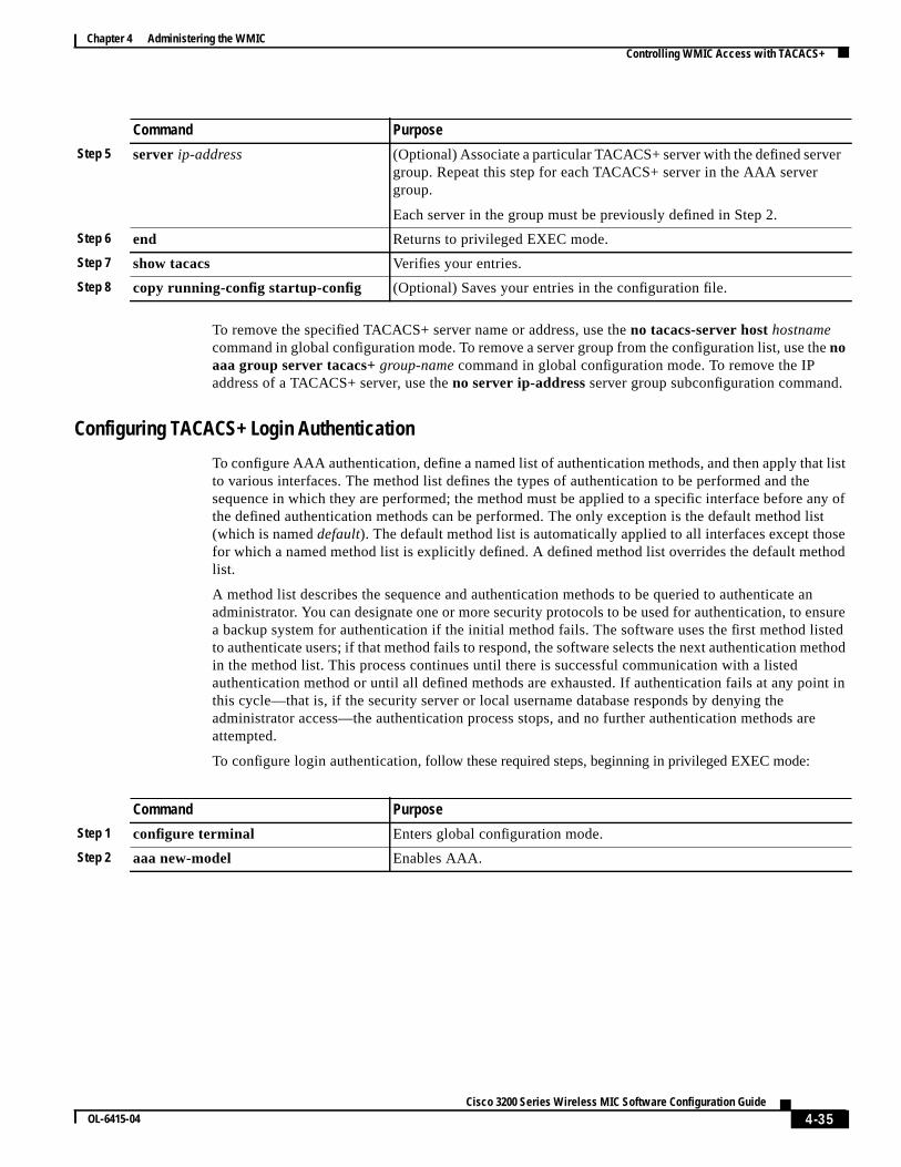
4-35Cisco 3200 Series Wireless MIC Software Configuration Guide
OL-6415-04
Chapter 4 Administering the WMIC Controlling WMIC Access with TACACS+
To remove the specified TACACS+ server name or address, use theno tacacs-server hosthostnamecommand in global configuration mode. To remove a server group from the configuration list, use thenoaaa group server tacacs+group-name command in global configuration mode. To remove the IPaddress of a TACACS+ server, use theno server ip-address server group subconfiguration command.
Configuring TACACS+ Login Authentication
To configure AAA authentication, define a named list of authentication methods, and then apply that listto various interfaces. The method list defines the types of authentication to be performed and thesequence in which they are performed; the method must be applied to a specific interface before any ofthe defined authentication methods can be performed. The only exception is the default method list(which is nameddefault). The default method list is automatically applied to all interfaces except thosefor which a named method list is explicitly defined. A defined method list overrides the default methodlist.
A method list describes the sequence and authentication methods to be queried to authenticate anadministrator. You can designate one or more security protocols to be used for authentication, to ensurea backup system for authentication if the initial method fails. The software uses the first method listedto authenticate users; if that method fails to respond, the software selects the next authentication methodin the method list. This process continues until there is successful communication with a listedauthentication method or until all defined methods are exhausted. If authentication fails at any point inthis cycle—that is, if the security server or local username database responds by denying theadministrator access—the authentication process stops, and no further authentication methods areattempted.
To configure login authentication, follow these required steps, beginning in privileged EXEC mode:
Step 5 server ip-address (Optional) Associate a particular TACACS+ server with the defined servergroup. Repeat this step for each TACACS+ server in the AAA servergroup.
Each server in the group must be previously defined in Step 2.
Step 6 end Returns to privileged EXEC mode.
Step 7 show tacacs Verifies your entries.
Step 8 copy running-config startup-config (Optional) Saves your entries in the configuration file.
Command Purpose
Command Purpose
Step 1 configure terminal Enters global configuration mode.
Step 2 aaa new-model Enables AAA.

4-36Cisco 3200 Series Wireless MIC Software Configuration Guide
OL-6415-04
Chapter 4 Administering the WMIC Controlling WMIC Access with TACACS+
To disable AAA, use theno aaa new-model command in global configuration mode. To disable AAAauthentication, use the no aaa authentication login {default | list-name} method1 [method2...]command in global configuration mode. To either disable TACACS+ authentication for logins or toreturn to the default value, use theno login authentication {default | list-name} command in lineconfiguration mode.
Configuring TACACS+ Authorization for Privileged EXEC Access and NetworkServices
AAA authorization limits the services that are available to a user. When AAA authorization is enabled,the WMIC uses information retrieved from the user’s profile, which is located either in the local userdatabase or on the security server, to configure the user’s session. The user is granted access to arequested service only if the information in the user profile allows it.
You can use theaaa authorizationcommand in global configuration mode with thetacacs+keyword toset parameters that restrict a user’s network access to privileged EXEC mode.
Step 3 aaa authentication login {default |list-name} method1 [method2...]
Create a login authentication method list.
• To create a default list that is used when a named list isnot specifiedin the login authentication command, use thedefault keywordfollowed by the methods that are to be used in default situations. Thedefault method list is automatically applied to all interfaces.
• For list-name, specify a character string as the name the list you arecreating.
• For method1..., specify the actual method that the authenticationalgorithm tries. The additional methods of authentication are usedonly if the previous method returns an error, not if it fails.
Select one of these methods:
• local—Use the local username database for authentication. You mustenter username information into the database. Use theusernamepassword global configuration command.
• tacacs+—Use TACACS+ authentication. You must configure theTACACS+ server before you can use this authentication method.
Step 4 line [console | tty | vty] line-number[ending-line-number]
Enters line configuration mode, and configure the lines to which you wantto apply the authentication list.
Step 5 login authentication {default |list-name}
Apply the authentication list to a line or a set of lines.
• If you specifydefault, use the default list created with theaaaauthentication login command.
• For list-name, specify the list created with theaaa authenticationlogin command.
Step 6 end Returns to privileged EXEC mode.
Step 7 show running-config Verifies your entries.
Step 8 copy running-config startup-config (Optional) Saves your entries in the configuration file.
Command Purpose
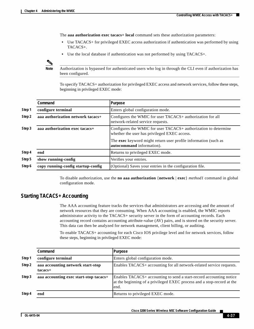
4-37Cisco 3200 Series Wireless MIC Software Configuration Guide
OL-6415-04
Chapter 4 Administering the WMIC Controlling WMIC Access with TACACS+
The aaa authorization exec tacacs+ localcommand sets these authorization parameters:
• Use TACACS+ for privileged EXEC access authorization if authentication was performed by usingTACACS+.
• Use the local database if authentication was not performed by using TACACS+.
Note Authorization is bypassed for authenticated users who log in through the CLI even if authorization hasbeen configured.
To specify TACACS+ authorization for privileged EXEC access and network services,follow these steps,beginning in privileged EXEC mode:
To disable authorization, use theno aaa authorization {network | exec} method1 command in globalconfiguration mode.
Starting TACACS+ Accounting
The AAA accounting feature tracks the services that administrators are accessing and the amount ofnetwork resources that they are consuming. When AAA accounting is enabled, the WMIC reportsadministrator activity to the TACACS+ security server in the form of accounting records. Eachaccounting record contains accounting attribute-value (AV) pairs, and is stored on the security server.This data can then be analyzed for network management, client billing, or auditing.
To enable TACACS+ accounting for each Cisco IOS privilege level and for network services, followthese steps, beginning in privileged EXEC mode:
Command Purpose
Step 1 configure terminal Enters global configuration mode.
Step 2 aaa authorization network tacacs+ Configures the WMIC for user TACACS+ authorization for allnetwork-related service requests.
Step 3 aaa authorization exec tacacs+ Configures the WMIC for user TACACS+ authorization to determinewhether the user has privileged EXEC access.
Theexec keyword might return user profile information (such asautocommand information).
Step 4 end Returns to privileged EXEC mode.
Step 5 show running-config Verifies your entries.
Step 6 copy running-config startup-config (Optional) Saves your entries in the configuration file.
Command Purpose
Step 1 configure terminal Enters global configuration mode.
Step 2 aaa accounting network start-stoptacacs+
Enables TACACS+ accounting for all network-related service requests.
Step 3 aaa accounting exec start-stop tacacs+ Enables TACACS+ accounting to send a start-record accounting noticeat the beginning of a privileged EXEC process and a stop-record at theend.
Step 4 end Returns to privileged EXEC mode.

4-38Cisco 3200 Series Wireless MIC Software Configuration Guide
OL-6415-04
Chapter 4 Administering the WMIC Configuring the WMIC for Local Authentication and Authorization
To disable accounting, use theno aaa accounting{ network | exec} { start-stop} method1...commandin global configuration mode.
Displaying the TACACS+ ConfigurationTo display TACACS+ server statistics, use theshow tacacs command in privileged EXEC mode.
Configuring the WMIC for Local Authentication andAuthorization
You can configure AAA to operate without a server by setting the WMIC to implement AAA in localmode. The WMIC then handles authentication and authorization. No accounting is available in thisconfiguration.
To configure the WMIC for local AAA, follow these steps, beginning in privileged EXEC mode:
Step 5 show running-config Verifies your entries.
Step 6 copy running-config startup-config (Optional) Saves your entries in the configuration file.
Command Purpose
Command Purpose
Step 1 configure terminal Enters global configuration mode.
Step 2 aaa new-model Enables AAA.
Step 3 aaa authentication login default local Sets the login authentication to use the local username database. Thedefault keyword applies the local user database authentication to allinterfaces.
Step 4 aaa authorization exec local Configures user AAA authorization to check the local database todetermine whether the user is allowed to run an EXEC shell.
Step 5 aaa authorization network local Configures user AAA authorization for all network-related servicerequests.

4-39Cisco 3200 Series Wireless MIC Software Configuration Guide
OL-6415-04
Chapter 4 Administering the WMIC Configuring the WMIC for Secure Shell
To disable AAA, use theno aaa new-model command in global configuration mode. To disableauthorization, use theno aaa authorization {network | exec} method1 command in globalconfiguration mode.
Configuring the WMIC for Secure ShellThis section describes how to configure the Secure Shell (SSH) feature.
Note For complete syntax and usage information for the commands used in this section, see the “Secure ShellCommands” section in theCisco IOS Security Command Reference for Release 12.2.
Understanding SSHSSH is a protocol that provides a secure, remote connection to a Layer 2 or a Layer 3 device. There aretwo versions of SSH: SSH version 1 and SSH version 2. Cisco IOS release 12.3(8)JK supports only SSHversion 1.
SSH provides greater security for remote connections than Telnet provides. When a device isauthenticated, SSH provides strong encryption. The SSH feature has an SSH server and an SSHintegrated client. The client supports these user authentication methods:
• RADIUS (for more information, see the“Controlling WMIC Access with RADIUS” section onpage 4-21)
• Local authentication and authorization (for more information, see the“Configuring the WMIC forLocal Authentication and Authorization” section on page 4-38)
Step 6 usernamename [privilege level]{ passwordencryption-type password}
Enters the local database, and establish a username-based authenticationsystem.
Repeat this command for each user.
• For name, specify the user ID as one word. Spaces and quotationmarks are not allowed.
• (Optional) Forlevel, specify the privilege level the user has aftergaining access. The range is from 0 to 15. Level 15 gives privilegedEXEC mode access. Level 0 gives user EXEC mode access.
• Forencryption-type, enter0 to specify that an unencrypted passwordfollows. Enter7 to specify that a hidden password follows.
• Forpassword, specify the password the user must enter to gain accessto the WMIC. The password must be from 1 to 25 characters, cancontain embedded spaces, and must be the last option specified in theusername command.
Step 7 end Returns to privileged EXEC mode.
Step 8 show running-config Verifies your entries.
Step 9 copy running-config startup-config (Optional) Saves your entries in the configuration file.
Command Purpose

4-40Cisco 3200 Series Wireless MIC Software Configuration Guide
OL-6415-04
Chapter 4 Administering the WMIC Managing Aironet Extensions
For more information about SSH, see the “Configuring Secure Shell” section in theCisco IOS SecurityConfiguration Guide for Release 12.2.
Note The SSH feature in Cisco IOS release 12.3(8)JK does not support IP Security (IPSec).
Configuring SSHBefore you configure SSH, download the crypto software image from Cisco.com. For information aboutconfiguring SSH and displaying SSH settings, see the “Configuring Secure Shell” section in theCiscoIOS Security Configuration Guide for Release 12.2.
Managing Aironet ExtensionsThe WMIC uses Cisco Aironet 802.11 extensions to detect the capabilities of Cisco client devices andto support features that require specific interaction between the WMIC and associated client devices.The Aironet extensions can be deactivated only in the root access point mode. Since workgroup bridge,root device, and non-root bridge are Cisco-specific modes, they always use the Aironet extensions.
Aironet extensions must be enabled to support the following features:
• Load balancing—The WMIC uses Aironet extensions to direct client devices to an access point thatprovides the best connection to the network, based on such factors as number of users, bit error rates,and signal strength.
• Message Integrity Check (MIC)—MIC is an additional WEP security feature that prevents attackson encrypted packets calledbit-flip attacks. The MIC, implemented on both the WMIC and allassociated client devices, adds a few bytes to each packet to make the packets tamper-proof.
• Temporal Key Integrity Protocol (TKIP)—TKIP, also known asWEP key hashing, is an additionalWEP security feature that defends against an attack on WEP in which the intruder uses anunencrypted segment called theinitialization vector(IV) in encrypted packets to calculate the WEPkey.
• Limiting the power level on associated client devices—When a client device associates to theWMIC, the WMIC sends the maximum allowed power level setting to the client.
To disable the Aironet extensions, follow these steps, beginning in privileged EXEC mode:
If you change the radio to a role that requires Aironet extensions, the Aironet extensions are enabledautomatically:
wmic1(config)# int dot 0
Command Purpose
Step 1 configure terminal Enters global configuration mode.
Step 2 interface dot11radio 0 Enters interface configuration mode for the radio interface.
Step 3 station-role root ap-only Enters the station role. Root enables the access point mode.
Step 4 no dot11 extension aironet Enters theextension aironet command to disable extensions.
Step 5 end Returns to privileged EXEC mode.
Step 6 copy running-config startup-config (Optional) Saves your entries in the configuration file.
4-41Cisco 3200 Series Wireless MIC Software Configuration Guide
OL-6415-04
Chapter 4 Administering the WMIC Managing the System Time and Date
wmic1(config-if)# station-role rootSelected role requires Cisco Aironet Extension enabled.Enabled Cisco Aironet Extension.
If you try to change the Aironet extensions without setting the radio to the proper role, an error messagedisplays:
wmic1(config-if)#wmic1(config-if)# no dot11 extension aironetAironet Extension is always enabled in Bridge or WGB mode.
Managing the System Time and DateYou can manage the system time and date on your WMIC automatically, by using the Network TimeProtocol (NTP), or manually, by setting the time and date on the WMIC.
Note For complete syntax and usage information for the commands used in this section, see theCisco IOSConfiguration Fundamentals Command Reference for Release 12.2.
Understanding the System ClockThe heart of the time service is the system clock. This clock runs from the moment that the system startsup. The system clock keeps track of the date and time.
The system clock can then be set from these sources:
• Network Time Protocol
• Manual configuration
The system clock determines time internally, based on Universal Time Coordinated (UTC), also knownas Greenwich Mean Time (GMT). You can configure information about the local time zone and summertime (daylight saving time) so that the time is correctly displayed for the local time zone.
The system clock keeps track of whether the time isauthoritativeor not (that is, whether it has been setby a time source considered to be authoritative). If it is not authoritative, the time is available only fordisplay purposes and is not redistributed. For configuration information, see the“Configuring Time andDate Manually” section on page 4-43.
Understanding Network Time ProtocolThe NTP is designed to time-synchronize a network of devices. NTP is documented in RFC 1305.
An NTP network usually gets its time from an authoritative time source, such as a radio clock or anatomic clock attached to a time server. NTP then distributes this time across the network. NTP isextremely efficient; no more than one packet per minute is necessary to synchronize two devices towithin a millisecond of each other.
NTP uses the concept of astratum to describe how many NTP hops away a device is from anauthoritative time source. A stratum 1 time server has a radio or atomic clock directly attached, astratum 2 time server receives its time through NTP from a stratum 1 time server, and so on.

4-42Cisco 3200 Series Wireless MIC Software Configuration Guide
OL-6415-04
Chapter 4 Administering the WMIC Managing the System Time and Date
A device running NTP automatically chooses as its time source the device with the lowest stratumnumber with which it communicates through NTP. This strategy effectively builds a self-organizing treeof NTP speakers.
NTP compares the time reported by several devices and does not synchronize to a device whose time issignificantly different than the others, even if its stratum is lower.
The communications between devices running NTP (known asassociations) are usually staticallyconfigured; each device is given the IP address of all the devices with which it should form associations.Accurate timekeeping is possible by exchanging NTP messages between associated devices. However,in a LAN environment, NTP can be configured to use IP broadcast messages instead. This alternativereduces configuration complexity because each device can simply be configured to send or receivebroadcast messages. However, in that case, information flow is one-way only.
The time kept on a device is a critical resource; you should use the security features of NTP to avoid theaccidental or malicious setting of an incorrect time. Two mechanisms are available: an access-list-basedrestriction scheme and an encrypted authentication mechanism.
Cisco’s implementation of NTP does not support stratum 1 service; it is not possible to connect to a radioor atomic clock. We recommend that the time service for your network be derived from the public NTPservers available on the IP Internet.Figure 4-2 shows a typical network example using NTP.
If the network is isolated from the Internet, Cisco’s implementation of NTP allows a device to act asthough it is synchronized through NTP, when in fact it has determined the time by using other means.Other devices then synchronize to that device through NTP.
When multiple sources of time are available, NTP is always considered to be more authoritative. NTPtime overrides the time set by any other method.
Several manufacturers include NTP software for their host systems, and a publicly available version forsystems running UNIX and its various derivatives is also available. The NTP software allows hostsystems to be time-synchronized as well.

4-43Cisco 3200 Series Wireless MIC Software Configuration Guide
OL-6415-04
Chapter 4 Administering the WMIC Managing the System Time and Date
Figure 4-2 Typical NTP Network Configuration
Catalyst 3550switch
Catalyst 3550switch
Catalyst 3550switch
Catalyst 3550switch
These switches are configured inNTP server mode (server association)with the Catalyst 6500 series switch.
Catalyst 6500series switch(NTP master)
This switch is configured as an NTPpeer to the upstream and downstreamCatalyst 3550 switches.
Catalyst 3550switch
Workstations
Workstations
Localworkgroup
servers
4326
9
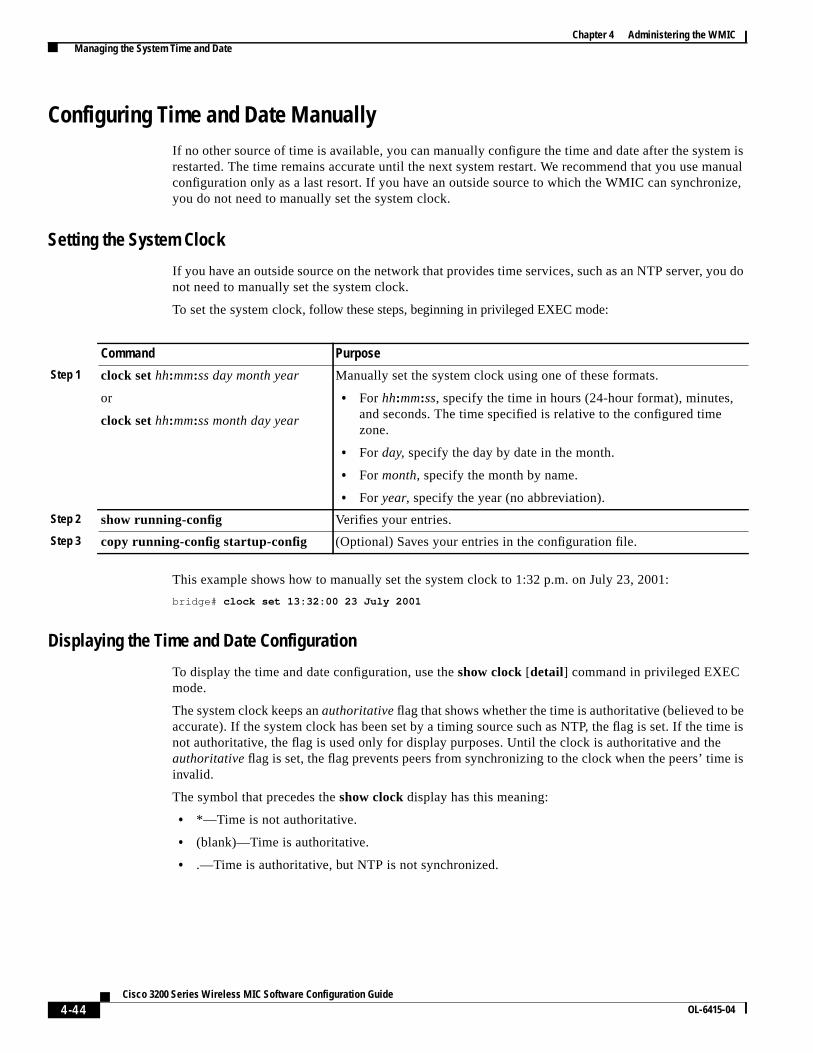
4-44Cisco 3200 Series Wireless MIC Software Configuration Guide
OL-6415-04
Chapter 4 Administering the WMIC Managing the System Time and Date
Configuring Time and Date ManuallyIf no other source of time is available, you can manually configure the time and date after the system isrestarted. The time remains accurate until the next system restart. We recommend that you use manualconfiguration only as a last resort. If you have an outside source to which the WMIC can synchronize,you do not need to manually set the system clock.
Setting the System Clock
If you have an outside source on the network that provides time services, such as an NTP server, you donot need to manually set the system clock.
To set the system clock, follow these steps, beginning in privileged EXEC mode:
This example shows how to manually set the system clock to 1:32 p.m. on July 23, 2001:
bridge# clock set 13:32:00 23 July 2001
Displaying the Time and Date Configuration
To display the time and date configuration, use theshow clock [detail] command in privileged EXECmode.
The system clock keeps anauthoritativeflag that shows whether the time is authoritative (believed to beaccurate). If the system clock has been set by a timing source such as NTP, the flag is set. If the time isnot authoritative, the flag is used only for display purposes. Until the clock is authoritative and theauthoritativeflag is set, the flag prevents peers from synchronizing to the clock when the peers’ time isinvalid.
The symbol that precedes theshow clock display has this meaning:
• *—Time is not authoritative.
• (blank)—Time is authoritative.
• .—Time is authoritative, but NTP is not synchronized.
Command Purpose
Step 1 clock sethh:mm:ss day month year
or
clock sethh:mm:ss month day year
Manually set the system clock using one of these formats.
• For hh:mm:ss, specify the time in hours (24-hour format), minutes,and seconds. The time specified is relative to the configured timezone.
• For day, specify the day by date in the month.
• For month, specify the month by name.
• For year, specify the year (no abbreviation).
Step 2 show running-config Verifies your entries.
Step 3 copy running-config startup-config (Optional) Saves your entries in the configuration file.
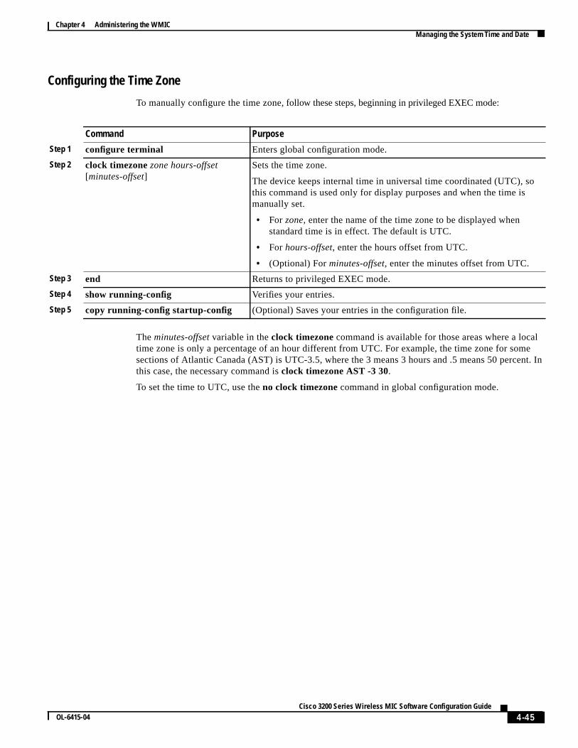
4-45Cisco 3200 Series Wireless MIC Software Configuration Guide
OL-6415-04
Chapter 4 Administering the WMIC Managing the System Time and Date
Configuring the Time Zone
To manually configure the time zone, follow these steps, beginning in privileged EXEC mode:
Theminutes-offset variable in theclock timezone command is available for those areas where a localtime zone is only a percentage of an hour different from UTC. For example, the time zone for somesections of Atlantic Canada (AST) is UTC-3.5, where the 3 means 3 hours and .5 means 50 percent. Inthis case, the necessary command isclock timezone AST -3 30.
To set the time to UTC, use theno clock timezone command in global configuration mode.
Command Purpose
Step 1 configure terminal Enters global configuration mode.
Step 2 clock timezonezone hours-offset[minutes-offset]
Sets the time zone.
The device keeps internal time in universal time coordinated (UTC), sothis command is used only for display purposes and when the time ismanually set.
• For zone, enter the name of the time zone to be displayed whenstandard time is in effect. The default is UTC.
• For hours-offset, enter the hours offset from UTC.
• (Optional) Forminutes-offset, enter the minutes offset from UTC.
Step 3 end Returns to privileged EXEC mode.
Step 4 show running-config Verifies your entries.
Step 5 copy running-config startup-config (Optional) Saves your entries in the configuration file.

4-46Cisco 3200 Series Wireless MIC Software Configuration Guide
OL-6415-04
Chapter 4 Administering the WMIC Managing the System Time and Date
Configuring Summer Time (Daylight Saving Time)
To configure daylight saving time in areas where it starts and ends on a particular day of the week eachyear, follow these steps, beginning in privileged EXEC mode:
The first part of theclock summer-timecommand specifies when daylight savings time begins, and thesecond part specifies when it ends. All times are relative to the local time zone. The start time is relativeto standard time. The end time is relative to daylight savings time. If the starting month is after theending month, the system assumes that you are in the southern hemisphere.
This example shows how to specify that summer time starts on the first Sunday in April at 02:00 andends on the last Sunday in October at 02:00:
bridge(config)# clock summer-time PDT recurring 1 Sunday April 2:00 last Sunday October2:00
Command Purpose
Step 1 configure terminal Enters global configuration mode.
Step 2 clock summer-timezonerecurring[week day month hh:mm week day monthhh:mm [offset]]
Configures summer time to start and end on the specified days every year.
Summer time is disabled by default. If you specifyclock summer-timezonerecurring without parameters, the summer time rules default to theUnited States rules.
• Forzone, specify the name of the time zone (for example, PDT) to bedisplayed when summer time is in effect.
• (Optional) Forweek, specify the week of the month (1 to 5 orlast).
• (Optional) Forday, specify the day of the week (Sunday, Monday...).
• (Optional) Formonth, specify the month (January, February...).
• (Optional) Forhh:mm, specify the time (24-hour format) in hours andminutes.
• (Optional) Foroffset, specify the number of minutes to add duringsummer time. The default is 60.
Step 3 end Returns to privileged EXEC mode.
Step 4 show running-config Verifies your entries.
Step 5 copy running-config startup-config (Optional) Saves your entries in the configuration file.

4-47Cisco 3200 Series Wireless MIC Software Configuration Guide
OL-6415-04
Chapter 4 Administering the WMIC Managing the System Time and Date
Configuring NTPWMICs do not have a hardware-supported clock, and they cannot function as an NTP master clock towhich peers synchronize when an external NTP source is not available. These devices also have nohardware support for a calendar. As a result, thentp update-calendar and thentp master commandsare not available.
Default NTP Configuration
Table 4-4 shows the default NTP configuration.
NTP is disabled by default.
Configuring NTP Authentication
This procedure must be coordinated with the administrator of the NTP server; the information youconfigure in this procedure must be matched by the servers that the WMIC uses to synchronize its timeto the NTP server.
To authenticate the associations (communications between devices running NTP that provide foraccurate timekeeping) with other devices, follow these steps, beginning in privileged EXEC mode:
Table 4-4 Default NTP Configuration
Feature Default Setting
NTP authentication Disabled. No authentication key is specified.
NTP peer or server associations None configured.
NTP broadcast service Disabled; no interface sends or receives NTP broadcast packets.
NTP access restrictions No access control is specified.
NTP packet source IP address The source address is determined by the outgoing interface.
Command Purpose
Step 1 configure terminal Enters global configuration mode.
Step 2 ntp authenticate Enables the NTP authentication feature, which is disabled bydefault.
Step 3 ntp authentication-key numbermd5 value Defines the authentication keys. By default, none are defined.
• For number, specify a key number. The range is from 1 to4294967295.
• md5 specifies that message authentication support is providedby using the message digest algorithm 5 (MD5).
• For value, enter an arbitrary string of up to eight characters forthe key.
The WMIC does not synchronize to a device unless both it and thedevice have an authentication key, and the key number is specifiedby thentp trusted-key key-number command.

4-48Cisco 3200 Series Wireless MIC Software Configuration Guide
OL-6415-04
Chapter 4 Administering the WMIC Managing the System Time and Date
To disable NTP authentication, use theno ntp authenticatecommand in global configuration mode. Toremove an authentication key, use theno ntp authentication-keynumber command in globalconfiguration mode. To disable authentication of the identity of a device, use theno ntp trusted-keykey-number command in global configuration mode.
This example shows how to configure the WMIC to synchronize only to devices providing authenticationkey 42 in the device’s NTP packets:
bridge(config)# ntp authenticatebridge(config)# ntp authentication-key 42 md5 aNiceKeybridge(config)# ntp trusted-key 42
Step 4 ntp trusted-key key-number Specifies one or more key numbers (defined in Step 3) that a peerNTP device must provide in its NTP packets for this WMIC tosynchronize to it.
By default, no trusted keys are defined.
For key-number, specify the key defined in Step 3.
This command provides protection against accidentallysynchronizing the WMIC to any untrusted device.
Step 5 end Returns to privileged EXEC mode.
Step 6 show running-config Verifies your entries.
Step 7 copy running-config startup-config (Optional) Saves your entries in the configuration file.
Command Purpose

4-49Cisco 3200 Series Wireless MIC Software Configuration Guide
OL-6415-04
Chapter 4 Administering the WMIC Managing the System Time and Date
Configuring NTP Associations
An NTP association can be a peer association (the WMIC can either synchronize to the other device orallow the other device to synchronize to it), or it can be a server association (the WMIC synchronizes tothe other device; the device does not synchronize to the WMIC).
To form an NTP association with another device,follow these steps, beginning in privileged EXEC mode:
You need to configure only one end of an association; the other device can automatically establish theassociation. If you are using the default NTP version (version 3), but NTP synchronization does notoccur, try using NTP version 2. Many NTP servers on the Internet run version 2.
To remove a peer or server association, use theno ntp peer ip-addressor theno ntp server ip-addresscommand in global configuration mode.
This example shows how to configure the WMIC to synchronize its system clock with the clock of thepeer at IP address 172.16.22.44, using NTP version 2:
bridge(config)# ntp server 172.16.22.44 version 2
Command Purpose
Step 1 configure terminal Enters global configuration mode.
Step 2 ntp peer ip-address [version number][key keyid] [sourceinterface] [prefer]
or
ntp server ip-address[version number][key keyid] [sourceinterface] [prefer]
Configures the WMIC system clock to synchronize a peer or to besynchronized by a peer (peer association).
or
Configures the WMIC system clock to be synchronized by a time server(server association).
No peer or server associations are defined by default.
• For ip-addressin a peer association, specify the IP address of the peerthat is providing, or that is being provided, the clock synchronization.For a server association, specify the IP address of the time server thatis providing the clock synchronization.
• (Optional) Fornumber, specify the NTP version number. The range isfrom 1 to 3. By default, version 3 is selected.
• (Optional) Forkeyid, enter the authentication key defined with thentp authentication-key command.
• (Optional) Forinterface, specify the interface from which to pick theIP source address. By default, the source IP address is taken from theoutgoing interface.
• (Optional) Enter theprefer keyword to make this peer or server thepreferred one that provides synchronization. This keyword reducesswitching between peers and servers.
Step 3 end Returns to privileged EXEC mode.
Step 4 show running-config Verifies your entries.
Step 5 copy running-config startup-config (Optional) Saves your entries in the configuration file.

4-50Cisco 3200 Series Wireless MIC Software Configuration Guide
OL-6415-04
Chapter 4 Administering the WMIC Managing the System Time and Date
Configuring NTP Broadcast Service
The communications between devices running NTP (known asassociations) are usually staticallyconfigured; each device is given the IP addresses of all the devices with which it should formassociations. Accurate timekeeping is possible by exchanging NTP messages between associateddevices. However, in a LAN environment, NTP can be configured to use IP broadcast messages instead.This alternative reduces configuration complexity because each device can be configured only to sendbroadcast messages or to receive broadcast messages. However, the information flow is one-way only.
The WMIC cansend or receive NTP broadcast packets on an interface-by-interface basis if there is an NTPbroadcast server, such as a router, broadcasting time information on the network. TheWMIC cansend NTPbroadcast packets to a peer so that the peer can synchronize to it. TheWMIC canalso receive NTP broadcastpackets to synchronize its own clock. This section provides procedures for sending and receiving NTPbroadcast packets.
To configure the WMIC to send NTP broadcast packets to peers so that they can synchronize their clockto the WMIC, follow these steps, beginning in privileged EXEC mode:
To disable the interface from sending NTP broadcast packets, use theno ntp broadcast interfaceconfiguration command.
This example shows how to configure an interface to send NTP version 2 packets:
bridge(config)# interface gigabitethernet0/1bridge(config-if)# ntp broadcast version 2
Command Purpose
Step 1 configure terminal Enters global configuration mode.
Step 2 interface interface-id Enters interface configuration mode, and specify the interface to sendNTP broadcast packets.
Step 3 ntp broadcast [versionnumber] [key keyid][destination-address]
Enables the interface to send NTP broadcast packets to a peer.
By default, this feature is disabled on all interfaces.
• (Optional) Fornumber, specify the NTP version number. Therange is 1 to 3. If you do not specify a version, version 3 is used.
• (Optional) Forkeyid, specify the authentication key to use whensending packets to the peer.
• (Optional) Fordestination-address, specify the IP address of thepeer that is synchronizing its clock to this WMIC.
Step 4 end Returns to privileged EXEC mode.
Step 5 show running-config Verifies your entries.
Step 6 copy running-config startup-config (Optional) Saves your entries in the configuration file.

4-51Cisco 3200 Series Wireless MIC Software Configuration Guide
OL-6415-04
Chapter 4 Administering the WMIC Managing the System Time and Date
Now you are ready to configure the connected peers to receive NTP broadcast packets, as described inthe next procedure. To configure the WMIC to receive NTP broadcast packets from connected peers,follow these steps, beginning in privileged EXEC mode:
To disable an interface from receiving NTP broadcast packets, use theno ntp broadcast clientcommandin configuration mode. To change the estimated round-trip delay to the default, use theno ntpbroadcastdelay command in global configuration mode.
This example shows how to configure an interface to receive NTP broadcast packets:
bridge(config)# interface gigabitethernet0/1bridge(config-if)# ntp broadcast client
Command Purpose
Step 1 configure terminal Enters global configuration mode.
Step 2 interface interface-id Enters interface configuration mode, and specifies the interface to receiveNTP broadcast packets.
Step 3 ntp broadcast client Enables the interface to receive NTP broadcast packets.
By default, no interfaces receive NTP broadcast packets.
Step 4 exit Returns to global configuration mode.
Step 5 ntp broadcastdelaymicroseconds (Optional) Changes the estimated round-trip delay between the WMICand the NTP broadcast server.
The default is 3000 microseconds; the range is from 1 to 999999.
Step 6 end Returns to privileged EXEC mode.
Step 7 show running-config Verifies your entries.
Step 8 copy running-config startup-config (Optional) Saves your entries in the configuration file.
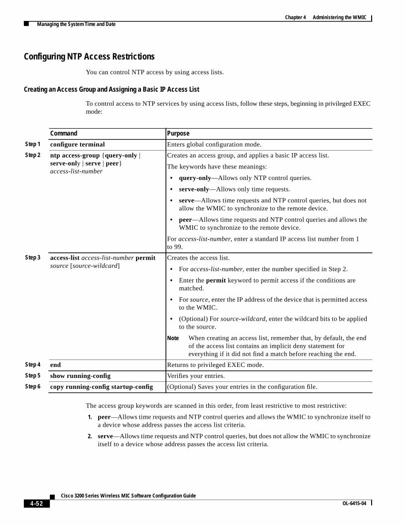
4-52Cisco 3200 Series Wireless MIC Software Configuration Guide
OL-6415-04
Chapter 4 Administering the WMIC Managing the System Time and Date
Configuring NTP Access Restrictions
You can control NTP access by using access lists.
Creating an Access Group and Assigning a Basic IP Access List
To control access to NTP services by using access lists,follow these steps, beginning in privileged EXECmode:
The access group keywords are scanned in this order, from least restrictive to most restrictive:
1. peer—Allows time requests and NTP control queries and allows the WMIC to synchronize itself toa device whose address passes the access list criteria.
2. serve—Allows time requests and NTP control queries, but does not allow the WMIC to synchronizeitself to a device whose address passes the access list criteria.
Command Purpose
Step 1 configure terminal Enters global configuration mode.
Step 2 ntp access-group {query-only |serve-only | serve | peer}access-list-number
Creates an access group, and applies a basic IP access list.
The keywords have these meanings:
• query-only—Allows only NTP control queries.
• serve-only—Allows only time requests.
• serve—Allows time requests and NTP control queries, but does notallow the WMIC to synchronize to the remote device.
• peer—Allows time requests and NTP control queries and allows theWMIC to synchronize to the remote device.
For access-list-number, enter a standard IP access list number from 1to 99.
Step 3 access-list access-list-numberpermitsource [source-wildcard]
Creates the access list.
• For access-list-number, enter the number specified in Step 2.
• Enter thepermit keyword to permit access if the conditions arematched.
• Forsource, enter the IP address of the device that is permitted accessto the WMIC.
• (Optional) Forsource-wildcard, enter the wildcard bits to be appliedto the source.
Note When creating an access list, remember that, by default, the endof the access list contains an implicit deny statement foreverything if it did not find a match before reaching the end.
Step 4 end Returns to privileged EXEC mode.
Step 5 show running-config Verifies your entries.
Step 6 copy running-config startup-config (Optional) Saves your entries in the configuration file.

4-53Cisco 3200 Series Wireless MIC Software Configuration Guide
OL-6415-04
Chapter 4 Administering the WMIC Managing the System Time and Date
3. serve-only—Allows only time requests from a device whose address passes the access list criteria.
4. query-only—Allows only NTP control queries from a device whose address passes the access listcriteria.
If the source IP address matches the access lists for more than one access type, the first access type isgranted. If no access groups are specified, all access types are granted to all devices. If any access groupsare specified, only the specified access types are granted.
To remove access control to the WMIC NTP services, use theno ntp access-group {query-only |serve-only | serve | peer} command in global configuration mode.
This example shows how to configure the WMIC to allow itself to synchronize to a peer from accesslist 99. However, the WMIC restricts access to allow only time requests from access list 42:
bridge# configure terminalbridge(config)# ntp access-group peer 99bridge(config)# ntp access-group serve-only 42bridge(config)# access-list 99 permit 172.20.130.5bridge(config)# access list 42 permit 172.20.130.6
Disabling NTP Services on a Specific Interface
NTP services are enabled on all interfaces by default.
To disableNTP packets from being received on an interface, follow these steps, beginning in privilegedEXEC mode:
To reenable receipt of NTP packets on an interface, use theno ntp disable command in interfaceconfiguration mode.
Command Purpose
Step 1 configure terminal Enters global configuration mode.
Step 2 interface interface-id Enters interface configuration mode, and specify the interface to disable.
Step 3 ntp disable Disables NTP packets from being received on the interface.
By default, all interfaces receive NTP packets.
Step 4 end Returns to privileged EXEC mode.
Step 5 show running-config Verifies your entries.
Step 6 copy running-config startup-config (Optional) Saves your entries in the configuration file.

4-54Cisco 3200 Series Wireless MIC Software Configuration Guide
OL-6415-04
Chapter 4 Administering the WMIC Managing the System Time and Date
Configuring the Source IP Address for NTP Packets
When the WMIC sends an NTP packet, the source IP address is normally set to the address of theinterface through which the NTP packet is sent. Use thentp source command in global configurationmode when you want to use a particular source IP address for all NTP packets. The address is taken fromthe specified interface. This command is useful if the address on an interface cannot be used as thedestination for reply packets.
To configure a specific interface from which the IP source address is to be taken, follow these steps,beginning in privileged EXEC mode:
The specified interface is used for the source address for all packets sent to all destinations. If a sourceaddress is to be used for a specific association, use thesource keyword in thentp peer or ntp servercommand in global configuration mode as described in the“Configuring NTP Associations” section onpage 4-48.
Displaying the NTP Configuration
To display NTP information, use the following commands in privileged EXEC mode:
• show ntp associations [detail]
• show ntp status
For detailed information about the fields in these displays, see theCisco IOS ConfigurationFundamentals Command Reference for Release 12.1.
Command Purpose
Step 1 configure terminal Enters global configuration mode.
Step 2 ntp source type number Specifies the interface type and number from which the IP source addressis taken.
By default, the source address is determined by the outgoing interface.
Step 3 end Returns to privileged EXEC mode.
Step 4 show running-config Verifies your entries.
Step 5 copy running-config startup-config (Optional) Saves your entries in the configuration file.
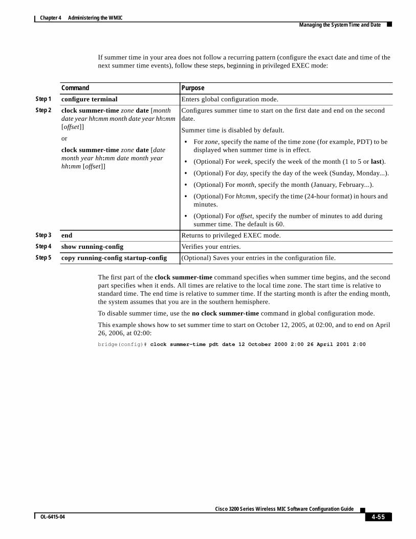
4-55Cisco 3200 Series Wireless MIC Software Configuration Guide
OL-6415-04
Chapter 4 Administering the WMIC Managing the System Time and Date
If summer time in your area does not follow a recurring pattern (configure the exact date and time of thenext summer time events), follow these steps, beginning in privileged EXEC mode:
The first part of theclock summer-timecommand specifies when summer time begins, and the secondpart specifies when it ends. All times are relative to the local time zone. The start time is relative tostandard time. The end time is relative to summer time. If the starting month is after the ending month,the system assumes that you are in the southern hemisphere.
To disable summer time, use theno clock summer-time command in global configuration mode.
This example shows how to set summer time to start on October 12, 2005, at 02:00, and to end on April26, 2006, at 02:00:
bridge(config)# clock summer-time pdt date 12 October 2000 2:00 26 April 2001 2:00
Command Purpose
Step 1 configure terminal Enters global configuration mode.
Step 2 clock summer-timezonedate [monthdate year hh:mm month date year hh:mm[offset]]
or
clock summer-timezonedate [datemonth year hh:mm date month yearhh:mm [offset]]
Configures summer time to start on the first date and end on the seconddate.
Summer time is disabled by default.
• Forzone, specify the name of the time zone (for example, PDT) to bedisplayed when summer time is in effect.
• (Optional) Forweek, specify the week of the month (1 to 5 orlast).
• (Optional) Forday, specify the day of the week (Sunday, Monday...).
• (Optional) Formonth, specify the month (January, February...).
• (Optional) Forhh:mm, specify the time (24-hour format) in hours andminutes.
• (Optional) Foroffset, specify the number of minutes to add duringsummer time. The default is 60.
Step 3 end Returns to privileged EXEC mode.
Step 4 show running-config Verifies your entries.
Step 5 copy running-config startup-config (Optional) Saves your entries in the configuration file.

4-56Cisco 3200 Series Wireless MIC Software Configuration Guide
OL-6415-04
Chapter 4 Administering the WMIC Managing the System Time and Date