Embed Size (px)
Citation preview

K5982V2 11/06 Rev. A
ADEMCO MX8000ADEMCO MX8000ADEMCO MX8000ADEMCO MX8000 Digital Alarm ReceiverDigital Alarm ReceiverDigital Alarm ReceiverDigital Alarm Receiver
Installation and Operation Guide

ii
Table of Contents Section 1 System Overview.....................................................................................................................................1–1
1.1 Features ................................................................................................................................................................1–1 1.2 Optional Accessories...........................................................................................................................................1–1 1.3 Formats Compatible with the MX8000..............................................................................................................1–2 1.4 MX8000 Supported SIA Digital I-III Levels.......................................................................................................1–3 1.5 How to Use this Manual ......................................................................................................................................1–3 1.6 Terminology ..........................................................................................................................................................1–4 1.7 What’s in the Box .................................................................................................................................................1–4 1.8 General Recommendations, Notes, and Limitations ......................................................................................1–5 1.9 How to Contact Technical Support ....................................................................................................................1–8
Section 2 Agency Requirements............................................................................................................................2–1 2.1 Telephone Requirements....................................................................................................................................2–1 2.2 FCC Statement.....................................................................................................................................................2–1 2.3 Industry Canada Statements..............................................................................................................................2–1 2.4 UL Requirements .................................................................................................................................................2–2 2.4.1 Hardware Requirements .....................................................................................................................................2–2 2.4.2 Operational Requirements..................................................................................................................................2–3 2.4.3 Programming Requirements ..............................................................................................................................2–3
Section 3 Installation.................................................................................................................................................3–1 3.1 Quick Start ............................................................................................................................................................3–1 3.2 Environmental specifications..............................................................................................................................3–1 3.3 Electrical Specifications ......................................................................................................................................3–1 3.4 Overview................................................................................................................................................................3–2 3.5 Rack Mounting......................................................................................................................................................3–3 3.6 Hot Swapping of Line Cards...............................................................................................................................3–4 3.7 Line Card Installation...........................................................................................................................................3–5 3.8 Removing Line Cards ..........................................................................................................................................3–7 3.9 Telephone Line Connection................................................................................................................................3–7 3.10 Parallel Printer Connection.................................................................................................................................3–7 3.10.1 Printer Cable Pin-Outs ........................................................................................................................................3–8 3.10.2 Com Ports 1 and 2 ...............................................................................................................................................3–9 3.10.3 Remote Alert Output ............................................................................................................................................3–9 3.11 AC Power Cord Connection ...............................................................................................................................3–9 3.11.1 Switching to a 240 VAC Power Supply.............................................................................................................3–9 3.11.2 How to Verify Earth Ground..............................................................................................................................3–10 3.12 Battery Connection ............................................................................................................................................3–11 3.13 Automation Computer Connection ..................................................................................................................3–12 3.13.1 Computer Port Baud Rate Selection ...............................................................................................................3–12 3.14 Master/Slave Receiver Linking.........................................................................................................................3–12 3.14.1 Receiver Linking Cabling Connections ...........................................................................................................3–12 3.14.2 Master/Slave Linking Programming ................................................................................................................3–13
Section 4 Operation...................................................................................................................................................4–1 4.1 Touchpad Function Buttons................................................................................................................................4–1 4.2 Displays .................................................................................................................................................................4–2 4.2.1 LED Displays ........................................................................................................................................................4–3 4.2.2 VFD Status Display..............................................................................................................................................4–3 4.3 Initial System Power Up......................................................................................................................................4–4 4.4 Log On / Log Off...................................................................................................................................................4–5 4.4.1 Installer Profile......................................................................................................................................................4–5 4.4.2 Operator Profile ....................................................................................................................................................4–5 4.4.3 Default User Codes .............................................................................................................................................4–5 4.4.4 How to log on the system. ..................................................................................................................................4–5 4.4.5 How to log off the system. ..................................................................................................................................4–6 4.5 Modes of Operation .............................................................................................................................................4–6 4.5.1 Normal Mode ........................................................................................................................................................4–6 4.5.2 Program Mode......................................................................................................................................................4–7

iii
4.6 Main Menu ............................................................................................................................................................4–7 4.6.1 How to Display the Main Menu ..........................................................................................................................4–7 4.6.2 How to Maneuver Through Main Menu ............................................................................................................4–8 4.6.3 Call History............................................................................................................................................................4–8 4.6.4 System History .....................................................................................................................................................4–9 4.6.5 System Info ...........................................................................................................................................................4–9 4.6.6 Set Time & Date ...................................................................................................................................................4–9 4.6.7 System Restart ...................................................................................................................................................4–10 4.6.8 Printer Menu .......................................................................................................................................................4–11 4.6.9 Program Menu....................................................................................................................................................4–16 4.6.10 Diagnostics Menu...............................................................................................................................................4–16 4.7 Listen-In and Hang Up ......................................................................................................................................4–19 4.7.1 Extend Manual (Common) Listen-In Operation.............................................................................................4–19 4.7.2 PBX Operation....................................................................................................................................................4–20 4.8 Testing the System ............................................................................................................................................4–20
Section 5 Programming............................................................................................................................................5–1 5.1 UL 864 Programming Requirements.................................................................................................................5–1 5.2 How to Enter Program Mode..............................................................................................................................5–1 5.2.1 Programming Fields.............................................................................................................................................5–1 5.2.2 How to Maneuver Around in Program Mode....................................................................................................5–2 5.3 Programming Choices.........................................................................................................................................5–2 5.4 General Options ...................................................................................................................................................5–2 5.4.1 Operation Mode....................................................................................................................................................5–6 5.4.2 Display Options ....................................................................................................................................................5–7 5.4.3 Communications.................................................................................................................................................5–12 5.4.4 System Options ..................................................................................................................................................5–22 5.4.5 Message Queue Options ..................................................................................................................................5–25 5.4.6 Slave List .............................................................................................................................................................5–26 5.4.7 Virtual Receiver/Line Numbers ........................................................................................................................5–27 5.5 Line Device Menu ..............................................................................................................................................5–28 5.5.1 Add Line Device .................................................................................................................................................5–38 5.5.2 Edit Line – MX8000–LC3 (3 Line) ...................................................................................................................5–38 5.5.3 Edit Line – MX8000–LRR .................................................................................................................................5–53 5.5.4 Edit Line – MX8000–LC1 (1 Line) ...................................................................................................................5–56 5.5.5 Copy Device(s) ...................................................................................................................................................5–68 5.5.6 Clear Device .......................................................................................................................................................5–70 5.5.7 View Devices ......................................................................................................................................................5–70 5.6 User List ..............................................................................................................................................................5–71 5.6.1 Adding a User .....................................................................................................................................................5–71 5.6.2 Editing a User .....................................................................................................................................................5–72 5.6.3 Clearing a User Out of the Receiver ...............................................................................................................5–73
Section 6 Compatible Reporting Formats ...........................................................................................................6–1 6.1 Formats By Communication Group. ..................................................................................................................6–1 6.2 Format Numbers Used In Printer Output..........................................................................................................6–3
Section 7 Troubleshooting ......................................................................................................................................7–1 7.1 Error Messages ....................................................................................................................................................7–1 7.2 Unrecognized Reports.........................................................................................................................................7–4 7.3 Troubleshooting Process ....................................................................................................................................7–4 7.3.1 Removing the CPU, PS, User Interface Assembly .........................................................................................7–5 7.3.2 Replacing the CPU, PS, User Interface Assembly .........................................................................................7–5 7.4 Safe Mode.............................................................................................................................................................7–5
Section 8 Automation Communication Formats................................................................................................8–1 8.1 Introduction ...........................................................................................................................................................8–1 8.1.1 Conventions Observed In This Section ............................................................................................................8–1 8.2 MX8000 Automation Protocols ..........................................................................................................................8–1 8.3 Reporting Formats and Automation Protocol Support....................................................................................8–2 8.4 ADEMCO 8000.....................................................................................................................................................8–3 8.4.1 AE Header Block..................................................................................................................................................8–3 8.4.2 Call Message Block .............................................................................................................................................8–3

iv
8.4.3 System Message Block.......................................................................................................................................8–7 8.4.4 Heart Beat Message Block .................................................................................................................................8–8 8.4.5 Validation Byte (V-Byte) ......................................................................................................................................8–9 8.4.6 ACKing and NACKing Data ................................................................................................................................8–9 8.4.7 Commands Initiated by the Automation Computer .........................................................................................8–9 8.5 ADEMCO 685 Automation Protocol ................................................................................................................8–13 8.5.1 Low Speed 3x1, 4x1, and 4x1 Express Automation Protocols....................................................................8–13 8.5.2 Low Speed 4x2 and 4x2 Express Automation Protocols .............................................................................8–13 8.5.3 ADEMCO High Speed Automation Protocols ................................................................................................8–13 8.5.4 685 Contact ID....................................................................................................................................................8–14 8.5.5 MX8000/685 System Messages ......................................................................................................................8–20 8.6 CAPS Automation Protocol ..............................................................................................................................8–20 8.7 FBII CP-220 Automation Protocol ...................................................................................................................8–22 8.7.1 3x1, 4x1, and 4x2 Automation Protocols ........................................................................................................8–22 8.7.2 Acron 11 Digit with Zero or Space...................................................................................................................8–22 8.7.3 FBII Superfast.....................................................................................................................................................8–22 8.7.4 CP-220 Contact ID.............................................................................................................................................8–22 8.7.5 CP-220/Silent Knight .........................................................................................................................................8–23 8.7.6 MX8000/CP-220 System Messages ...............................................................................................................8–24 8.8 SK9000 Protocol ................................................................................................................................................8–25 8.8.1 Data String Description And Special Characters...........................................................................................8–25 8.8.2 Calls From Panels..............................................................................................................................................8–26 8.8.3 Long Calls ...........................................................................................................................................................8–26 8.8.4 Bad Data..............................................................................................................................................................8–27 8.8.5 Good Data with Bad Data .................................................................................................................................8–27 8.8.6 Validation Byte (V-Byte) ....................................................................................................................................8–27 8.8.7 System Messages..............................................................................................................................................8–28 8.8.8 Communication from a Computer to the MX8000.........................................................................................8–28 8.9 ITI Generic Computer Format ..........................................................................................................................8–29 8.9.1 Convention Used In This Section ....................................................................................................................8–29 8.9.2 Report Record ....................................................................................................................................................8–29 8.9.3 Log Record..........................................................................................................................................................8–31 8.9.4 Test Record ........................................................................................................................................................8–32 8.9.5 OKAY Record .....................................................................................................................................................8–32 8.9.6 ACKing and NACKing Data ..............................................................................................................................8–32 8.10 ITI Computer Interface Format.........................................................................................................................8–32 8.10.1 Convention Used In This Section ....................................................................................................................8–32 8.10.2 General Record Structure.................................................................................................................................8–33 8.10.3 Report Record ....................................................................................................................................................8–33 8.10.4 Test Record ........................................................................................................................................................8–36 8.10.5 Supervisory Record ...........................................................................................................................................8–37 8.10.6 Log Records........................................................................................................................................................8–37 8.10.7 Checksum/Control Field....................................................................................................................................8–37 8.11 US ASCII Character Code ................................................................................................................................8–38
Appendix A Programming Quick Chart ................................................................................................................... A–1 Appendix B Receiver Update Procedure................................................................................................................. B–1 Appendix C Index .......................................................................................................................................................... C–1

v
List of Tables Table 1–1: Optional Accessories for the MX8000 Receiver ...........................................................................................1–2 Table 1–2: Formats Compatible with the MX8000 ...........................................................................................................1–2 Table 1–3: MX8000 and SIA Levels I-III comparison ......................................................................................................1–3 Table 3–1: External Printer Cable Pin Description...........................................................................................................3–8 Table 4–1: Touchpad Buttons Description ........................................................................................................................4–2 Table 4–2: LED Description.................................................................................................................................................4–3 Table 4–3: VFD and Printer Abbreviations........................................................................................................................4–4 Table 4–4: Main Menu Option Items by Profile.................................................................................................................4–5 Table 4–5: Default User Codes...........................................................................................................................................4–5 Table 4–6: Printer Menu Choices .....................................................................................................................................4–11 Table 4–7: Event Format Choices and Meaning ............................................................................................................4–14 Table 4–8: Phantom Signals Formats List ......................................................................................................................4–16 Table 4–9: Abbreviation Display Character Meanings/High Low Status ....................................................................4–19 Table 5–1: Types of Programming Fields..........................................................................................................................5–1 Table 5–2: General Options Items and Description .........................................................................................................5–3 Table 5–3: Operation Mode Choices and Descriptions...................................................................................................5–6 Table 5–4: Display Options and Descriptions ...................................................................................................................5–7 Table 5–5: Communications Options and Description ..................................................................................................5–12 Table 5–6: Initialization String Characters.......................................................................................................................5–17 Table 5–7: ITI Automation Format Options .....................................................................................................................5–20 Table 5–8: On-board Annunciator and Auxiliary Relay Options ..................................................................................5–21 Table 5–9: System Options ...............................................................................................................................................5–22 Table 5–10: 685, CAPS, and CP-220 1–9/A–Z Entries.................................................................................................5–23 Table 5–11: Line Device Menu Options...........................................................................................................................5–29 Table 5–12: MX8000–LC3 Edit Line List Items and Description..................................................................................5–39 Table 5–13: Valid Programmable String Characters .....................................................................................................5–44 Table 5–14: Account Characters ......................................................................................................................................5–45 Table 5–15: Hexadecimal AlarmNet Number to Decimal Conversion ........................................................................5–55 Table 5–16: MX8000–LC1 Edit Line List Items and Description..................................................................................5–56 Table 5–17: User List Menu Items and Steps.................................................................................................................5–71 Table 5–18: Available Characters.....................................................................................................................................5–72 Table 6–1: Formats compatible with the MX8000............................................................................................................6–1 Table 6–2: Formats By Report Number.............................................................................................................................6–3 Table 7–1: Error Messages .................................................................................................................................................7–1 Table 8–1: Automation Protocol Listing .............................................................................................................................8–1 Table 8–2: Reporting Formats and Automation Protocol Support .................................................................................8–2 Table 8–3: AE Header Block Components Description...................................................................................................8–3 Table 8–4: Call Message Components and Description .................................................................................................8–3 Table 8–5: Dialer Format Types By Code .........................................................................................................................8–4 Table 8–6: Panel Data Identifiers and Descriptions.........................................................................................................8–4 Table 8–7: Call Message Components..............................................................................................................................8–5 Table 8–8: Call Message With Listen-in Data...................................................................................................................8–6 Table 8–9: Bad Data Field Indicator Components ...........................................................................................................8–7 Table 8–10: System Message Components .....................................................................................................................8–7 Table 8–11: System Messages...........................................................................................................................................8–8 Table 8–12: Link Test Components ...................................................................................................................................8–9 Table 8–13: Response Messages by the MX8000 Receiver........................................................................................8–10 Table 8–14: Command Requests by Identifiers .............................................................................................................8–10 Table 8–15: Log-in Request Components.......................................................................................................................8–10 Table 8–16: Log-off Request Components .....................................................................................................................8–11 Table 8–17: Force Hang-Up Request Components.......................................................................................................8–11 Table 8–18: Add Listen-in Account Request Components ...........................................................................................8–11 Table 8–19: Delete a Listen-in Account Request Components ...................................................................................8–11 Table 8–20: Extend Listen-in Period Request Components.........................................................................................8–12 Table 8–21: End Listen-in Period Request Components ..............................................................................................8–12

vi
Table 8–22: Delete a Listen-in Account Request Components ...................................................................................8–12 Table 8–23: Contact ID Event Definition Codes .............................................................................................................8–15 Table 8–24: MX8000/685 System Messages .................................................................................................................8–21 Table 8–25: MX8000/CP-220 System Messages ..........................................................................................................8–24 Table 8–26: Data String Description ................................................................................................................................8–25 Table 8–27: Special Characters Used in the Protocol...................................................................................................8–25 Table 8–28: System Messages.........................................................................................................................................8–28 Table 8–29: Number and ITI Digit Equivalent .................................................................................................................8–29 Table 8–30: Report Record Components........................................................................................................................8–29 Table 8–31: Upper Nibble Description .............................................................................................................................8–30 Table 8–32: Lower Nibble Description .............................................................................................................................8–30 Table 8–33: Extended Panel ID Codes (XID) .................................................................................................................8–30 Table 8–34: Alarm Code and Description........................................................................................................................8–31 Table 8–35: Log Record Components and Description ................................................................................................8–31 Table 8–36: Test Record Components and Description ...............................................................................................8–32 Table 8–37: Okay Record Components and Description..............................................................................................8–32 Table 8–38: Number and ITI Digit Equivalent .................................................................................................................8–33 Table 8–39: Type of Record Identifiers............................................................................................................................8–33 Table 8–40: Record Components.....................................................................................................................................8–33 Table 8–41: Report Record Components and Description ...........................................................................................8–34 Table 8–42: Information Field Identifiers .........................................................................................................................8–34 Table 8–43: Panel Type Characters.................................................................................................................................8–35 Table 8–44: Condition Codes and Descriptions .............................................................................................................8–36 Table 8–45: Test Record Information Fields and Descriptions ....................................................................................8–36 Table 8–46: Log Record Information Fields and Descriptions .....................................................................................8–37 Table 8–47: Checksum Verification Process ..................................................................................................................8–38 Table 8–48: US ASCII Character Code ...........................................................................................................................8–38 Table A–1: Programming Quick Chart..................................................................................................................................... A–1

vii
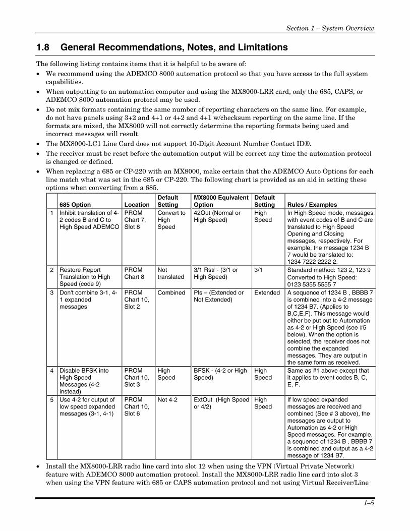
List of Figures Figure 3–1: MX8000 Front View ........................................................................................................................................3–2 Figure 3–2: MX8000 Front View Without Front Plate Attached ....................................................................................3–2 Figure 3–3: MX8000 Rear View.........................................................................................................................................3–2 Figure 3–4: Rack Mount Enclosure, Front View..............................................................................................................3–3 Figure 3–5: Rack Mount Enclosure, Rear View...............................................................................................................3–4 Figure 3–6: Line Card Locations........................................................................................................................................3–5 Figure 3–7: Line Card Position and Components ...........................................................................................................3–6 Figure 3–8: Parallel Printer Cable Connection to MX8000 ............................................................................................3–8 Figure 3–9: Wiring Sequence For Parallel Printer Port Interface..................................................................................3–8 Figure 3–10: MX8000 Remote Alert Output/Backup Battery Connection....................................................................3–9 Figure 3–11: CPU, PS, User Interface Assembly Retaining Screw Locations .........................................................3–10 Figure 3–12: Side View of CPU, PS, User Interface Assembly ..................................................................................3–10 Figure 3–13: Outlet Voltage Measurement Points ........................................................................................................3–11 Figure 3–14: Battery Connections ...................................................................................................................................3–11 Figure 3–15: 25-Pin Null Modem Cable Connection ....................................................................................................3–12 Figure 3–16: 9-Pin Null Modem Cable Connection.......................................................................................................3–12 Figure 3–17: MX8000 Master/Slave Receiver Linking Cabling Connections............................................................3–13 Figure 3–18: SBUS Receiver Linking Cable ..................................................................................................................3–14 Figure 4–1: MX8000 Front Panel.......................................................................................................................................4–1 Figure 4–2: Touchpad Layout ............................................................................................................................................4–1 Figure 4–3: VFD Display .....................................................................................................................................................4–3 Figure 4–4: Power-up Routine ...........................................................................................................................................4–4 Figure 4–5: Main Menu Display .........................................................................................................................................4–7 Figure 4–6: Main Menu Controls .......................................................................................................................................4–8 Figure 4–7: View of a Call History Screen........................................................................................................................4–8 Figure 4–8: System History Display Sequence ...............................................................................................................4–9 Figure 4–9: System Information Display...........................................................................................................................4–9 Figure 4–10: Setting Time and Date Program Sequence............................................................................................4–10 Figure 4–11: System Restart Display .............................................................................................................................4–10 Figure 4–12: Print Menu Items.........................................................................................................................................4–11 Figure 4–13: Print Report Menu Items............................................................................................................................4–12 Figure 4–14: Call History Options....................................................................................................................................4–12 Figure 4–15: System Configuration Print Items.............................................................................................................4–13 Figure 4–16: Event Format Menu Items .........................................................................................................................4–14 Figure 4–17: Program Menu Items..................................................................................................................................4–16 Figure 4–18: Diagnostics Menu Items ............................................................................................................................4–16 Figure 4–19: Message Queue Level ...............................................................................................................................4–17 Figure 4–20: Event Log Display.......................................................................................................................................4–17 Figure 4–21: Diagnostic Formats.....................................................................................................................................4–17 Figure 4–22: Select LC Debug Mode by Line Card ......................................................................................................4–17 Figure 4–23: Line Statistics Display ................................................................................................................................4–18 Figure 4–24: Port Status View of Serial Port .................................................................................................................4–18 Figure 4–25: Parallel Port Status View ...........................................................................................................................4–18 Figure 4–26: Phone Connector Pin-Out and Listen-in Wiring Diagram .....................................................................4–20 Figure 5–1: Programming Controls ...................................................................................................................................5–2 Figure 5–2: Program Menu Choices .................................................................................................................................5–2 Figure 5–3: General Options Display ................................................................................................................................5–2 Figure 5–4: Normal Operating Mode Display Indicating Manual Operation................................................................5–6 Figure 5–5: View of Display Options .................................................................................................................................5–7 Figure 5–6: Communications Options Menu..................................................................................................................5–12 Figure 5–7: Initialization String Display...........................................................................................................................5–16 Figure 5–8: System Options Display...............................................................................................................................5–22 Figure 5–9: Message Queue Display..............................................................................................................................5–25 Figure 5–10: Slave List Display .......................................................................................................................................5–26 Figure 5–11: Virtual Receiver/Line Numbers Display...................................................................................................5–27

viii
Figure 5–12: Choosing Line Device Menu and Line Device Program Menu Items .................................................5–28 Figure 5–13: MX8000–LC3 Handshake Sequence Menu ...........................................................................................5–39 Figure 5–14: MX8000–LC3 Handshake Order Number...............................................................................................5–39 Figure 5–15: MX8000–LC3 Line Options Menu ............................................................................................................5–42 Figure 5–16: MX8000–LC3 Listen Mode Menu Display...............................................................................................5–44 Figure 5–17: MX8000–LC3 Listen In Accounts Menu..................................................................................................5–45 Figure 5–18: MX8000–LC3 Miscellaneous Phone Line Options ................................................................................5–46 Figure 5–19: MX8000–LC3 Ring Options ......................................................................................................................5–48 Figure 5–20: MX8000–LC3 ADEMCO Auto Output Options .......................................................................................5–49 Figure 5–21: MX8000–LC3 Line Gain Options..............................................................................................................5–51 Figure 5–22: MX8000–LRR Line Edit .............................................................................................................................5–54 Figure 5–23: MX8000–LC1 Handshake Sequence Menu ...........................................................................................5–57 Figure 5–24: MX8000–LC1 Handshake Order Number...............................................................................................5–57 Figure 5–25: MX8000–LC1 Line Options Menu ............................................................................................................5–60 Figure 5–26: MX8000–LC1 Listen Mode Menu Display...............................................................................................5–62 Figure 5–27: MX8000–LC1 Listen In Accounts Menu..................................................................................................5–64 Figure 5–28: MX8000–LC1 Miscellaneous Phone Line Options ................................................................................5–65 Figure 5–29: MX8000–LC1 ADEMCO Auto Output Options .......................................................................................5–67 Figure 5–30: Visual Steps to Clear a Line From the Receiver ....................................................................................5–70 Figure 5–31: User List Menu Items .................................................................................................................................5–71 Figure 7–1: User CPU, PS, User Interface Assembly retaining Screw Locations......................................................7–5 Figure 8–1: 685 3x1, 4x1, 4x1 Express Protocol...........................................................................................................8–13 Figure 8–2: 685 4x2 and 4x2 Express Protocol.............................................................................................................8–13 Figure 8–3: 685 ADEMCO High Speed Protocol ..........................................................................................................8–14 Figure 8–4: 685 Contact ID Protocol...............................................................................................................................8–14 Figure 8–5: CAPS 4x2 and 4x2 Express Protocol ........................................................................................................8–20 Figure 8–6: CP-220 3x1, 4x1, 4x2 Protocol ...................................................................................................................8–22 Figure 8–7: CP-220 Acron 11 Digit Protocol..................................................................................................................8–22 Figure 8–8: CP-220 FBII Superfast Protocol .................................................................................................................8–22 Figure 8–9: CP-220 Contact ID Protocol ........................................................................................................................8–23 Figure 8–10: CP-220/Silent Knight Format 0 .................................................................................................................8–23 Figure 8–11: CP-220/Silent Knight Format 1 (FSK 1) ..................................................................................................8–23 Figure 8–12: CP-220/Silent Knight Format 6 (FSK 2) ..................................................................................................8–24 Figure 8–13: SK9000 Example Message.......................................................................................................................8–26 Figure 8–14: Long Event Data .........................................................................................................................................8–27 Figure 8–15: System Message ........................................................................................................................................8–28
1–1
Section 1 System Overview
This manual describes installation, operation, and programming of the MX8000 Digital Alarm Receiver. The MX8000 can be used as a desktop receiver, however it must be rack-mounted for UL Listed installations. This section will list features, optional accessories, compatible formats, and SIA options supported. This section also contains conventions held throughout the manual, terminology relevant to this product, and other information.
To ensure the best possible performance from this product, please check the Honeywell Online Support web site (HTTP://WWW.HONEYWELL.COM/SECURITY) for the latest code upgrades before placing this product into service.
1.1 Features Hardware: • Supports both 120 and 240 VAC installations at 60 and 50Hz operation. • External annunciation with auxiliary Form C dry contact relay. (Programmable) • On-board programmable piezo alert sounder. • 1 parallel port. • 2 serial ports. • 2 rear SBUS connectors. • Modular configuration for easy replacement and repair. • 4 line Vacuum Fluorescent Display (VFD) with 20 characters for each line. • On-board touchpad for manual operation and programming. • LEDs to indicate system operations. • Rack mountable design. • One line card will communicate with all supported formats. • Supports up to 12 3-port line cards where the ports operate independent of each other. • Line Device parameters are stored in the Master Central Processing Unit for faster removal and
replacement. • Line Devices support Caller ID. • Line Devices are individually programmable for format priority and ring parameters. • Line Devices support direct connect phone lines monitoring.
Software:
• Programmable display options for time and date information. • View or print the history information by priority or by call or by event. • Two user profiles to control user access to the receiver. • Supports up to 40 users. • Listen-in accounts support wild card variables. • Listen-in selectable for direct, hook flash, or PBX phone system. • Programmable port configuration for automation, printer and backup support. • 500 event history buffer.
1.2 Optional Accessories
Table 1–1 lists optional accessories for the MX8000 receiver. These accessories are available from our sales department unless otherwise indicated.

MX8000 Installation and Operation Guide
1–2
Table 1–1: Optional Accessories for the MX8000 Receiver
Item ADEMCO Model Number (if applicable)
Description/Comments
Three Line card MX8000–LC3 The 3 line card monitors the phone lines, detects ring and processes the message from the communicating panel.
One Line card MX8000–LC1 The 1 line card monitors a phone line, detects ring and processes the message from the communicating panel.
Radio Line card MX8000–LRR The radio line card interfaces to a transceiver and processes the message from the communicating panel.
CPU, PS, User Interface
MX8000–CPU The CPU, Power Supply, User Interface Assembly contains the VFD, main processing board, and receiver power supply.
Backup battery Acquire from a local retailer (See Section 3.12 for installation.)
A UL Fire Protection Services approved 12VDC 7AH battery such as a Powersonic PS-1270 that will provide a minimum 4 hours of backup power during an AC power loss. (See Section 2.4.2 for UL backup power requirements.)
Printer cable Acquire from a local retailer A standard 25-pin cable used to connect the MX8000 receiver to an external parallel printer.
SBUS cable Acquire from a local retailer A standard 4-wire RJ-11 reverse cable such as a Digi-Key H2642-14-ND that is used to connect the receivers together for receiver linking.
Rack-mounting cabinet
Acquire from a local retailer Used to rack mount the MX8000 receiver as required by UL. (See Section 2.4.1 for specifications and vendor information.)
Blank filler panels Acquire from a local retailer Used to fill up any unused cabinet spaces as required by UL. Parallel printer Acquire from a local retailer The ADEMCO MX8000 receiver requires a UL approved dot matrix parallel
printer such as the Okidata Microline 320 to generate a hardcopy of report history.
1.3 Formats Compatible with the MX8000
The MX8000 receiver is compatible with all ADEMCO UL Listed communicators. Table 1–2 shows the formats that the MX8000 receiver can decode and the handshake frequency groups that accommodate that format (see Section 5.5 for line device programming). Each line device can decode every format listed below. Setting the handshake order only prioritizes the type of communication done by each line device. Section 6 of this manual describes the formats in greater detail. Important Note: When selecting a reporting format and using an automation computer, it is essential that you check Table 8–2: Reporting Formats and Automation Protocol Support to verify that the reporting format selected is supported by the automation protocol that will be used.
Table 1–2: Formats Compatible with the MX8000 REPORTING FORMAT PPS or CPS REPORTING FORMAT PPS or CPS
3/1, 3/1 Ext 10, 20, or 40 PPS ITI UltraGard N/A 3/1 Even Round 10, 20, or 40 PPS Radionics Modem II N/A 3/1 w/cksum 10, 20, or 40 PPS Radionics Modem IIE N/A 3/1 Ext w/cksum 10, 20, or 40 PPS SIA DCS N/A 3/2 10, 20, or 40 PPS SX-III, SX-IVA N/A 3/2 Even Round 10, 20, or 40 PPS SX-IVB N/A 3/2 w/cksum 10, 20, or 40 PPS Varitech FSK 4/1 N/A 4/1, 4/1 Ext 10 PPS
FS
K (
con
t’d
)
Varitech FSK 4/2 N/A 4/1 Even Round 10 PPS 4/1 w/cksum 10 PPS
Acron Touchtone w/ 3-digit account
10 CPS
4/1 Ext w/cksum 10 PPS 4/2 10 PPS
Acron Touchtone w/ 4-digit account
10 CPS
4/2 Even Round 10 PPS ADEMCO 4/1 w/cksum 10 PPS
1400
/230
0 H
z P
uls
e
4/2 w/cksum 10 PPS ADEMCO 4/2 w/cksum 10 PPS BFSK N/A ADEMCO High Speed 10 CPS FSK0/FSK 80 N/A ADEMCO High Speed w/cksum 10 CPS FSK1/FSK 81 N/A Contact ID® 10 CPS FSK2/FSK 86 N/A Contact ID®10 10 CPS ITI CareTaker+, SecurityPro 4000 N/A FBII 4/3/1 10, 20, or 40 PPS ITI Commander N/A ITI Commander 2000, LifeGard N/A
FBII 4/3/1 w/cksum FBII Superfast
10, 20, or 40 PPS
ITI RF Commander, Harbor Gard N/A Westec 970 10 CPS
FS
K
ITI SX-V N/A
DT
MF
Westec 1000/2000/3000 10 CPS

Section 1 – System Overview
1–3
1.4 MX8000 Supported SIA Digital I-III Levels
Table 1–3 compares the MX8000 receiver to SIA Digital Compatibility Levels I, II, and III and indicates which of them we comply with.
Table 1–3: MX8000 and SIA Levels I-III comparison
8000 Function/Capability Transmitter Receiver
✔ Support Tonal Acknowledgments required required ✔ Support N blocks with Zone Numbers Only required required ✔ Support single Account Block per Call required required ✔ Support O Blocks (optional) required ✔ Support X Blocks (optional) required
Lev
el I
✔ Support 300 Baud (Fast) (optional) required
Support Configuration Block required required
Support Data Acknowledgments required required
✔ Support Modifier codes id, da and ti. (optional) required
✔ Support Multiple Account Blocks per Call (optional) required
✔ Support E Blocks (optional) required
Lev
el II
✔ Support Data Codes with Units Numbers (optional) required
Support RECEIVER call out and Access Passcode required required
Support Reverse Channel C Blocks required required
Support Reverse Channel P Blocks required (optional)
Support Reverse Channel A Blocks (optional) required
Support Dynamic block and Group Sizes (optional) required
✔ Support Listen-in (optional) required
✔ Support A Blocks to RECEIVER (optional) required
Lev
el II
I
Support V-Channel communication (optional) (optional)
1.5 How to Use this Manual
This manual contains information on how to install, operate and program the MX8000 receiver. We strongly suggest that the manual be reviewed in its entirety to become familiar with procedures and parameters of the product. Once you are familiar with the product, the manual can be used as a reference document.
This manual uses the following conventions:
• A small graphic of each touchpad button is used to represent which touchpad key is to be pressed for a
given operation. For example, an up-arrow would be shown as:
• VFD display This represents messages that appear on the VFD (display).
• 2225Hz This typeface represents an editable field that appears on the VFD (display).
• Pages of the manual are numbered by section. For example, a page numbered as “5-1” is Page 1 of Section 5.
• When this manual refers to default settings, it means programmable options set at the factory. Any programming after the receiver is powered up will change these setting.

MX8000 Installation and Operation Guide
1–4
1.6 Terminology
This section lists terminology that is specific to this product and their meaning.
Term Meaning
ACK Stands for acknowledgment.
Automation Protocol The format used for messages sent between the receiver and the automation computer.
Communication Group The different types of communication are separated by handshake type. These handshake types can be assigned in a numbered order. (See Section 5 for more details.)
Heartbeat A supervisory signal that continually tests the communication link between the automation computer and the receiver.
Listen-in Listen-in is the ability to listen in to what is happening real-time from the central station to a remote location. This can help the central station operator determine if he or she should dispatch for a particular alarm situation.
Main Menu The main menu will be displayed as either <Installer Menu> or <Operator Menu>. However, this manual will refer to them as the main menu.
MCPU Master Central Processing Unit.
NACK Stands for no acknowledgment.
PIN An abbreviation for Personal Identification Number. PINs are used to log in and out of the receiver.
PZT PZT is an abbreviation for a piezo alert sounder.
SBUS Serial Bus interface to connect a MX8000 receiver to line cards, the VFD display and additional MX8000 receivers via rear panel connectors.
VFD Stands for Vacuum Fluorescent Display. This is the type of message display used on the receiver.
VPN Stands for Virtual Private Network. VPN is a feature available with the MX8000-LRR line card and allows an increase in the number of accounts (in increments of 10,000) that can report to one LRR. When this feature is not used, the number of accounts that can report to one LRR is limited to 10,000.
1.7 What’s in the Box
This section contains a list of the parts that are shipped with the MX8000 receiver and a brief description of their intended use.
Item Quantity Description
Battery/Alert Relay Wiring Harness
1 Wiring harness used to connect the MX8000 receiver to a backup battery. It also provides a normally open or normally closed output for an alert sounder.
MX8000 Installation and Operation Guide
1 A manual covering installation and operation information related to the MX8000 receiver.
Digital Alarm Receiver 1 The digital alarm receiver assembly.
Line Card (See Note) 1 Line card for land lines.
Strain Relief Tie Wrap 1 Tie wrap used as a strain relief on the phone cord. See Figure 3–3 for location of strain relief tabs.
Receiver Mounting Screws 4 #10-32 x 3/8 flat head screws used to mount the receiver to a UL Listed rack. (See Section 3.5 for rack mounting instructions.)
Power Cable 1 AC power cable used to connect the MX8000 receiver to an AC wall plug.
Note: The system is shipped with either of two line cards dependent on the system ordered. If the MX8000-1 is ordered, the line card included is an MX8000-LC1 single line card. If an MX8000-3 is ordered, the line card included is an MX8000-LC3 tri-line card.
Section 1 – System Overview
1–5
1.8 General Recommendations, Notes, and Limitations
The following listing contains items that it is helpful to be aware of: • We recommend using the ADEMCO 8000 automation protocol so that you have access to the full system
capabilities. • When outputting to an automation computer and using the MX8000-LRR card, only the 685, CAPS, or
ADEMCO 8000 automation protocol may be used. • Do not mix formats containing the same number of reporting characters on the same line. For example,
do not have panels using 3+2 and 4+1 or 4+2 and 4+1 w/checksum reporting on the same line. If the formats are mixed, the MX8000 will not correctly determine the reporting formats being used and incorrect messages will result.
• The MX8000-LC1 Line Card does not support 10-Digit Account Number Contact ID®. • The receiver must be reset before the automation output will be correct any time the automation protocol
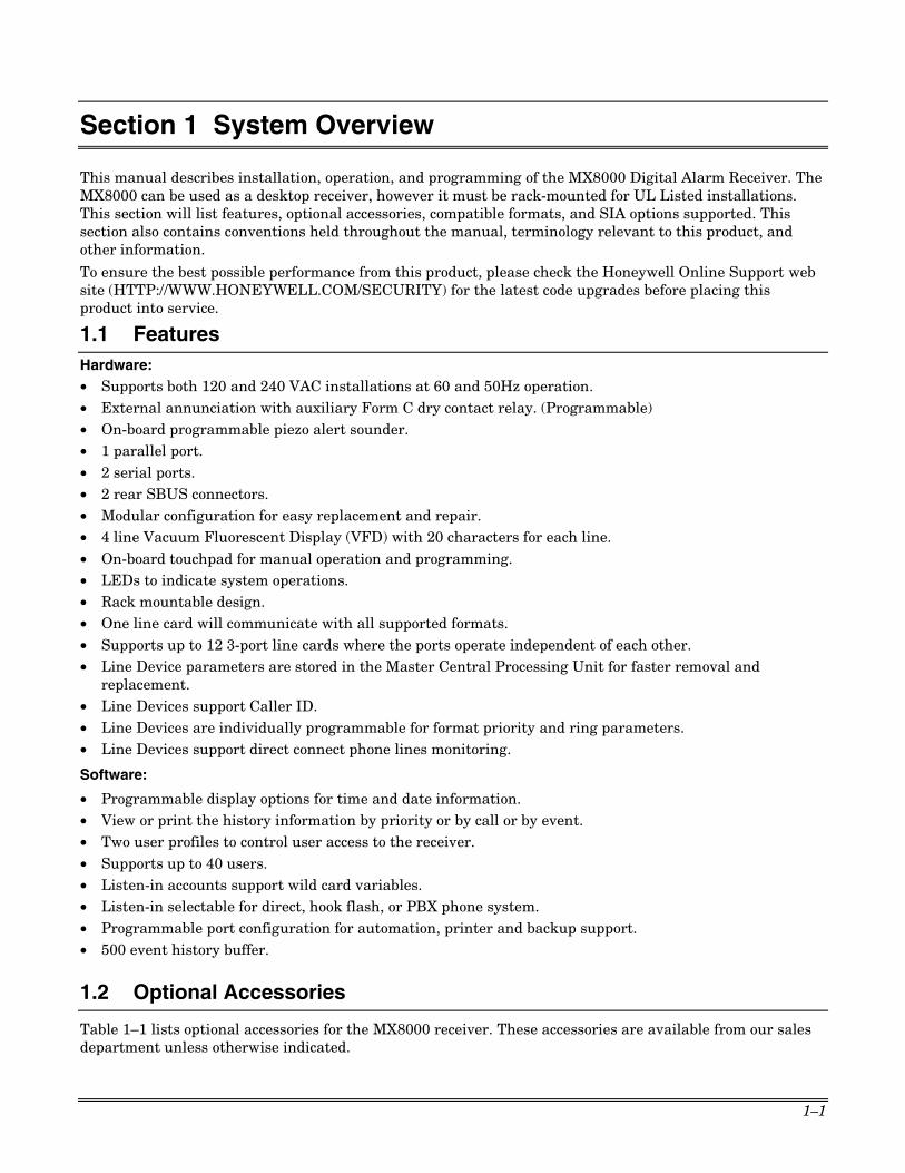
is changed or defined. • When replacing a 685 or CP-220 with an MX8000, make certain that the ADEMCO Auto Options for each
line match what was set in the 685 or CP-220. The following chart is provided as an aid in setting these options when converting from a 685.
685 Option Location Default Setting
MX8000 Equivalent Option
Default Setting Rules / Examples
1 Inhibit translation of 4-2 codes B and C to High Speed ADEMCO
PROM Chart 7, Slot 8
Convert to High Speed
42Out (Normal or High Speed)
High Speed
In High Speed mode, messages with event codes of B and C are translated to High Speed Opening and Closing messages, respectively. For example, the message 1234 B 7 would be translated to: 1234 7222 2222 2.
2 Restore Report Translation to High Speed (code 9)
PROM Chart 8
Not translated
3/1 Rstr - (3/1 or High Speed)
3/1 Standard method: 123 2, 123 9 Converted to High Speed: 0123 5355 5555 7
3 Don't combine 3-1, 4-1 expanded messages
PROM Chart 10, Slot 2
Combined Pls – (Extended or Not Extended)
Extended A sequence of 1234 B , BBBB 7 is combined into a 4-2 message of 1234 B7. (Applies to B,C,E,F). This message would either be put out to Automation as 4-2 or High Speed (see #5 below). When the option is selected, the receiver does not combine the expanded messages. They are output in the same form as received.
4 Disable BFSK into High Speed Messages (4-2 instead)
PROM Chart 10, Slot 3
High Speed
BFSK - (4-2 or High Speed)
High Speed
Same as #1 above except that it applies to event codes B, C, E, F.
5 Use 4-2 for output of low speed expanded messages (3-1, 4-1)
PROM Chart 10, Slot 6
Not 4-2 ExtOut (High Speed or 4/2)
High Speed
If low speed expanded messages are received and combined (See # 3 above), the messages are output to Automation as 4-2 or High Speed messages. For example, a sequence of 1234 B , BBBB 7 is combined and output as a 4-2 message of 1234 B7.
• Install the MX8000-LRR radio line card into slot 12 when using the VPN (Virtual Private Network) feature with ADEMCO 8000 automation protocol. Install the MX8000-LRR radio line card into slot 3 when using the VPN feature with 685 or CAPS automation protocol and not using Virtual Receiver/Line

MX8000 Installation and Operation Guide
1–6
numbers. When using the MX8000-LRR with the VPN feature, 685 or CAPS automation protocol, and Virtual Receiver Line numbers, assign the MX8000-LRR as line 8.
• When using the 685, CAPS, or CP-220 automation protocol, a limit applies to the number of line cards that should be used for proper processing by most automation systems. – The following examples apply when NOT using Virtual Receiver/Line numbers while using 685,
CAPS, or CP-220 automation protocols and are currently supported by most automation systems. 685 OR CAPS MODES - The example below allows up to 3 MX8000-LC3 cards giving 8 usable lines: For MX8000-LC3 (If using an LRR card, insert it as a replacement for the LC3 in slot 3.) Line Number 1 4 7 10 13 16 19 22 25 28 31 34 MX8000-LC3 (Y = used) Y Y Y N N N N N N N N N Device Slot 1 2 3 4 5 6 7 8 9 10 11 12 Alarms Report as Lines: 1,2,3 4,5,6 7,8 Line Faults as Line: 1,2,3 4,5,6 7,8
Notes: •••• Cards in slot 4 or higher may not be supported by your automation system when using 685, CAPS, or CP-220 automation protocol.
• Cards in slot 4 or higher cannot report alarms or line troubles correctly when ADEMCO 685 or CAPS automation protocol is chosen.
• Line 9 in slot 3 may not be used when using 685, CAPS, or CP-220.
CP-220 MODE - The example below allows up to 5 MX8000-LC3 cards giving 15 usable lines:
For MX8000-LC3 (LRR card not supported by CP-220 mode.) Line Number 1 4 7 10 13 16 19 22 25 28 31 34 MX8000-LC3 (Y = used) Y Y Y Y Y N N N N N N N Device Slot 1 2 3 4 5 6 7 8 9 10 11 12 Alarms Report as Lines: 1,2,3 4,5,6 7,8,9 A,B,C D,E,F Line Faults as Line: 1,2,3 4,5,6 7,8,9 A,B,C D,E,F
Notes: •••• Cards in slot 6 or higher may not be supported by your automation system when using CP-220 automation protocol.
• Cards in slot 6 or higher cannot report alarms or line troubles correctly when CP-220 automation protocol is chosen.
685 OR CAPS MODES - The example below allows 3 MX8000-LC1 cards only: For MX8000-LC1 (If using an LRR card, insert it as a replacement for the LC1 in slot 3.) Line Number 1 4 7 10 13 16 19 22 25 28 31 34 MX8000-LC1 (Y = used) Y Y Y N N N N N N N N N Device Slot 1 2 3 4 5 6 7 8 9 10 11 12 Alarms Report as Lines: 1 4 7 Line Faults as Line: 1 4 7
Notes: •••• Cards in slot 4 or higher may not be supported by your automation system when using 685, or CAPS automation protocol.
• Cards in slot 4 or higher cannot report alarms or line troubles correctly when ADEMCO 685 or CAPS automation protocol is chosen.
CP-220 MODE - The example below allows 5 MX8000-LC1 cards only: For MX8000-LC1 (LRR card not supported by CP-220 mode.) Line Number 1 4 7 10 13 16 19 22 25 28 31 34 MX8000-LC1 (Y = used) Y Y Y Y Y N N N N N N N Device Slot 1 2 3 4 5 6 7 8 9 10 11 12 Alarms Report as Lines: 1 4 7 A D Line Faults as Line: 1 4 7 A D
Notes: •••• Cards in slot 6 or higher may not be supported by your automation system when using CP-220 automation protocol.
• Cards in slot 6 or higher cannot report alarms or line troubles correctly when CP-220 automation protocol is chosen.

Section 1 – System Overview
1–7
The example below allows up to 8 MX8000-LC1 cards but lines 4-8 can only report line troubles as line 8 and this example is only allowable in 685 or CAPS (CP-220 not supported):
For MX8000-LC1 (If using an LRR card, insert it as a replacement for the LC1 in slot 8.)
Line Number 1 4 7 10 13 16 19 22 25 28 31 34
MX8000-LC1 (Y = used) Y Y Y Y Y Y Y Y N N N N
Device Slot 1 2 3 4 5 6 7 8 9 10 11 12
Hunt Group Setting 01 02 03 04 05 06 07 08
Alarms Report as Lines: 1 2 3 4 5 6 7 8
Line Faults as Line: 1 4 7 8 8 8 8 8
Note: Cards in slot 4 or higher may not be supported by your automation system when using CP-220 automation protocol.
– The following configurations apply when using 685, CAPS, or CP-220 automation protocols and are NOT currently supported by most automation systems. This information is presented to provide an understanding of what is sent to an automation system in the event any of these configurations are used. Important Note: The use of Virtual Receiver/Line Numbers is recommended.
The example below allows up to 12 MX8000-LC3 cards giving 36 usable lines:
For MX8000-LC3 (If using an LRR card, insert it as a replacement for the LC3 in slot 3. LRR card not supported by CP-220 mode.) Line Number 1 4 7 10 13 16 19 22 25 28 31 34 MX8000-LC3 (Y = used) Y Y Y Y Y Y Y Y Y Y Y Y
Device Slot 1 2 3 4 5 6 7 8 9 10 11 12
Alarms Report as Lines: 1,2,3 4,5,6 7,8,9 A,B,C D,E,F G,H,I J,K,L M,N,O P,Q,R S,T,U V,W,X Y,Z,a
Line Faults as Line: (685,CAPS) 1,2,3 4,5,6 7,8,8 8,8,8 8,8,8 8,8,8 8,8,8 8,8,8 8,8,8 8,8,8 8,8,8 8,8, 8
Line Faults as Line: (CP-220)
1,2,3 4,5,6 7,8,9 A,B,C D,E,F G,H,I J,K,L M,N,O P,Q,R S,T,U V,W,X Y,Z,a
Note: When 685 or CAPS automation is chosen, all lines above 8 will report as line 8 for phone line failures and restorals.
The example below allows 12 MX8000-LC1 cards giving 12 usable lines:
For MX8000-LC1 (If using an LRR card, insert it as a replacement for the LC1 in slot 3. LRR card not supported by CP-220 mode.)
Line Number 1 4 7 10 13 16 19 22 25 28 31 34
MX8000-LC1 (Y = used) Y Y Y Y Y Y Y Y Y Y Y Y
Device Slot 1 2 3 4 5 6 7 8 9 10 11 12
Alarms Report as Lines: 1 4 7 A D G J M P S V Y
Line Faults as Line: (685,CAPS)
1 4 7 8 8 8 8 8 8 8 8 8
Line Faults as Line: (CP-220) 1 4 7 A D G J M P S V Y
Note: When 685 or CAPS automation is chosen, all lines above 8 will report as line 8 for phone line failures and restorals.

MX8000 Installation and Operation Guide
1–8
1.9 How to Contact Technical Support
If you have a question or encounter a problem, please do the following before contacting technical support:
• Check all wiring connections.
• Determine that the power supply and/or backup battery are supplying proper voltages.
• Verify your programming information where applicable.
• Note the proper model number of this product, and the version level (if known) along with any documentation that came with the product.
• Note your Honeywell customer number and/or company name.
Having this information handy will make it easier for us to serve you quickly and effectively. Technical Support: 1-800-645-7492 (8 a.m.-8 p.m. EST) Digital Alarm Receiver Emergency After Hours Support: 1-800-421-5557 (8 p.m.-8 a.m. EST Monday
through Thursday and 8 p.m. Friday through 8 a.m. Monday)
FAXBACK Automated Fax Retrieval System: 1-800-573-0153 or 1-516-921-6704 / ext. 1667
World Wide Web Address: http://www.honeywell.com/security

2–1
Section 2 Agency Requirements
2.1 Telephone Requirements
If requested by the telephone company, the following information must be provided before connecting this device to the phone lines:
A. Manufacturer: Honeywell International Inc.
B. Model Number: MX8000
C. FCC Registration Number: US5GBOT01B46056
D. Type of jack (to be installed by the telephone company):
RJ31X or RJ11X
Ringer equivalence: 0.1B
This device may not be connected directly to coin telephones or party line services. The telephone company may make changes in its facilities, equipment, or procedures that could affect the operation of the equipment. If this happens, the telephone company will provide advance notice to allow you to make the necessary modifications to maintain uninterrupted service.
2.2 FCC Statement
FCC Class B Note: This equipment has been tested and found to comply with the limits for a Class B digital device, pursuant to part 15 of the FCC Rules. These limits are designed to provide reasonable protection against harmful interference in a residential installation. This equipment generates, uses, and can radiate radio frequency energy and, if not installed and used in accordance with the instructions, may cause harmful interference to radio communications. However, there is no guarantee that interference will not occur in a particular installation. If this equipment does cause harmful interference to radio or television reception, which can be determined by turning the equipment off and on, the user is encouraged to try to correct the interference by one or more of the following measures:
• reorient or relocate the receiving antenna.
• increase the separation between the equipment and receiver.
• connect the equipment into an outlet on a circuit different from that to which the receiver is connected.
• consult the dealer or an experienced radio/TV technician for help.
2.3 Industry Canada Statements
This Class B digital apparatus complies with Canadian ICES-003. Cet Appareil numérique de la classe B est conforme à la norme NMB-003 du Canada.
NOTICE: The Industry Canada Label identifies certified equipment. This certification means that the equipment meets telecommunications network protective, operational and safety requirements as prescribed in the appropriate Terminal Equipment Technical Requirements document(s). The Department does not guarantee the equipment will operate to the user’s satisfaction. Before installing this equipment, users should ensure that it is permissible to be connected to the facilities of the local telecommunications company. The equipment must also be installed using an acceptable method of connection. The customer should be aware that compliance with the above conditions might not prevent degradation of service in some situations.

MX8000 Installation and Operation Guide
2–2
Repairs to certified equipment should be coordinated by a representative designated by the supplier. Any repairs or alterations made by the user to this equipment, or equipment malfunctions, may give the telecommunications company cause to request the user to disconnect the equipment.
Users should ensure for their own protection that the electrical ground connections of the power utility, telephone lines and internal metallic water pipe system, if present, are connected together. This precaution may be particularly important in rural areas.
Caution: Users should not attempt to make such connections themselves but should contact appropriate electric inspection authority, or electrician, as appropriate.
INDUSTRIE CANADA AVIS: L’étiquette d’Industrie Canada identifie le matériel homologué. Cette étiquette certifie que le matériel est conforme aux normes de protection, d’exploitation et de sécurité des réseaux de télécommunications, comme le prescrivent les documents concernant les exigences techniques relatives au matériel terminal. Le Ministère n’assure toutefois pas que le matériel fonctionnera à la satisfaction de l’utilisateur. Avant d’installer ce matériel, l’utilisateur doit s’assurer qu’il est permis de le raccorder aux installations de l’enterprise locale de télécommunication. Le matériel doit également être installé en suivant une méthode acceptée da raccordement. L’abonné ne doit pas oublier qu’il est possible que la conformité aux conditions énoncées ci-dessus n’empêche pas la dégradation du service dans certaines situations. Les réparations de matériel nomologué doivent être coordonnées par un représentant désigné par le fournisseur. L’entreprise de télécommunications peut demander à l’utilisateur da débrancher un appareil à la suite de réparations ou de modifications effectuées par l’utilisateur ou à cause de mauvais fonctionnement. Pour sa propre protection, l’utilisateur doit s’assurer que tous les fils de mise à la terre de la source d’energie électrique, de lignes téléphoniques et des canalisations d’eau métalliques, s’il y en a, sont raccordés ensemble. Cette précaution est particulièrement importante dans les régions rurales.
Avertissement: L’utilisateur ne doit pas tenter de faire ces raccordements lui-même; il doit avoir racours à un service d’inspection des installations électriques, ou à un électricien, selon le cas.
AVIS: L’indice d’équivalence de la sonnerie (IES) assigné à chaque dispositif terminal indique le nombre maximal de terminaux qui peuvent être raccordés à une interface. La terminaison d’une interface téléphonique peut consister en une combinaison de quelques dispositifs, à la seule condition que la somme d’indices d’équivalence de la sonnerie de tous les dispositifs n’excède pas 5.
2.4 UL Requirements
Follow the procedures outlined in the sections below for listing as an NFPA 72 Central Station Service installation. The MX8000 is also suitable for household and commercial burglary service. Note that installation regulations are subject to the jurisdiction of a local authority.
2.4.1 Hardware Requirements See Figure 3–4 and Figure 3–5 (Section 3) for diagrams of a suggested installation. 1. A second MX8000 must be installed as a backup in case the primary MX8000 fails. The backup system
must be able to take over within 30 seconds. (Note: This requirement does not apply to burglary-only installations.)
2. The MX8000 must be housed in a metal rack-mounting cabinet that is UL Listed for fire protective signaling use. A recommended enclosure is a listed control unit accessories system cabinet, manufactured by Atlas/Soundelier. (The WA200 series, intended for 19-inch rack mount panels, can be used.) A taller cabinet could be used to house additional units.
3. Any unused front panel rack space must be filled with blank panels so that all wiring remains enclosed. 4. The external conduit must exit through the knockouts in the cabinet or go directly through the floor.

Section 2 – Agency Requirements
2–3
2.4.2 Operational Requirements 1. The transmitters reporting to the MX8000 must be UL Listed DACTs (digital alarm communicator
transmitters). 2. The central station must provide a minimum of 24 hours of backup power within 30 seconds of an AC
power loss. The backup must either be in the form of a UL Listed UPS or electrical generator. 3. If the MX8000 is not automated, the central station operator must check for the 24-hour test signals
from the communicators. (Note: This requirement does not apply to burglary-only installations.) 4. The connection between the MX8000 and the UL Listed computer should be according to the pin
configuration for Com Port 1 as shown in Section 3.13, Figure 3–15 and Figure 3–16, of this manual. (Note: This port is for ancillary use only.)
5. If a computer is used, the computer and its accessories must be installed in the same room as the receiver.
6. Com Port 2 is for ancillary use only. If used, the device connected to Com Port 2 must be installed in the same room as the receiver.
7. The UL Listed printer connected to the receiver printer port must be installed in the same room as the receiver.
8. When using a MX8000–LRR line card, the transceiver connected to the MX8000–LRR P1 connector must be installed in the same rooms as the receiver.
2.4.3 Programming Requirements In a UL Listed installation, the MX8000 receiver must be programmed according to the following procedure:
• Do NOT use the alarm output relay in UL installations.
• Each log-on code must have at least four digits.

MX8000 Installation and Operation Guide
2–4

3–1
Section 3 Installation
This section contains information necessary to install a MX8000 Digital Alarm Receiver.
IMPORTANT: Do not connect power to the system until you have read these instructions carefully.
3.1 Quick Start
The following procedure provides a quick start outline that may be used by installers who are familiar with the installation and programming of the MX8000 receiver. This procedure encompasses the basic installation and programming steps where the unit will be using mostly default values for operation. For complete installation procedures, bypass this section and observe the procedures in the balance of this manual. To perform the quick start installation, proceed as follows: 1. Install any additional line cards into the receiver. (See section 3.7 for additional information.) 2. Power up the receiver by plugging it into an AC outlet. (See section 3.11 for additional information.) 3. Log onto the receiver as the installer. (See section 4.4 for additional information.) 4. Set the receiver time and date. (See section 4.6.6 for additional information.) 5. Enter the program mode by selecting it from the main menu. 6. Select the operation mode for the receiver. (See section 5.4.1 for additional information.) 7. Configure communications and printer ports. (See section 5.4.3 for additional information.) 8. Define device (line card) types and options. (See section 5.5 for additional information.) 9. Select the automation protocol to be used. (See section 5.4.3.5 for additional information.) 10. Exit the program mode and log off the receiver.
3.2 Environmental specifications
• Temperature range is 32º to 120º F. • Indoor use only. • 85 percent non-condensing humidity. • Non-corrosive environment.
3.3 Electrical Specifications
Line Voltage: 120VAC, 60Hz, 100VA 240VAC, 50Hz, 100VA
Fuse: 2.5A Slow Blow
MX8000 230mA (with no Line Cards)
MX8000-LC1 40mA
MX8000-LC3 35mA
Current Draw: (VFD brightness at 50%, all lines on the line cards in trouble [LEDs On], Auxiliary Relay Off)
MX8000-LRR 75mA
Input 10.2 to 14.0 VDC 3 Amp Max. Backup Battery Connection: A 12 VDC battery does not provide standby time required by UL and NFPA standards. A UPS (listed for Protective Signaling Use) must be utilized when standby power is required. See 5.4.4 for details on backup battery configuration. Refer to Section 9 of UL827 for power requirements.
Output 13.65 VDC 1.7 Amp charging current
Auxiliary Relay: The relay field connection must be to a power limited source.
2.5 Amp @ 24VAC\VDC(Inductive), 0Hz 5 Amp @ 24VAC\VDC(Resistive), 0Hz

MX8000 Installation and Operation Guide
3–2
3.4 Overview
The MX8000 is assembled at the factory. One MX8000-LC3 tri-line card is shipped with the MX8000 receiver. Follow the procedures described in Section 3.7 to install additional line cards.
HOME HANGUP
CALL
PENDING
OPERATOR
LOGGED IN
SYSTEM
FAULT
SYSTEM
POWER
LISTEN
PREV
CALL
NEXT EVENT
NEXT
CALL
0
1 2
#
3
654
7 8 9
PREV EVENT
ACK
ENTER
MENU
31
32
33
34
35
36
28
29
30
22
23
24
25
26
27
19
20
21
13
14
15
16
17
18
10
11
12
4
5
6
7
8
9
1
2
3
LOG
STATUS
8765 12111094321
DEVICE
FRONT PLATESCREWS
FRONT PLATERETAINING PINS
Figure 3–1: MX8000 Front View
HOME HANGUP
CALLPENDING
OPERATORLOGGED IN
SYSTEMFAULT
SYSTEMPOWER
LISTEN
PREVCALL
NEXT EVENT
NEXTCALL
0
1 2
#
3
654
7 8 9
PREV EVENT
ACK
ENTER
MENU
LOG
STATUS
PHONE LINECONNECTORS
INSERTEDLINE CARD
PHONE LINESLOTS
LINE CARDGUIDES
P5P4P3P2
Figure 3–2: MX8000 Front View Without Front Plate Attached
COM 1
PARALLEL
100 VA
120 VAC ± 10%240 VAC ± 10%
50-60 Hz
WARNING!HIGH VOLTAGE PRESENT
DISCONNECT AC LINE ANDALL OTHER CONNECTORS
PROIR TO SERVICINGThis device complies with 47CFR Part 68Ademco Model MX8000Registration Number US5GB0T01B46056
This device has been verified to comply with FCC Rules Part 15.Operation is subject to the following two conditions: (1) Thisdevice may not cause radio interference, and (2) This device mustaccept any interference received including interference that maycause undesired operation.
Install in accordance with NFPA 72Central Station Service
PHONELINE
SLOTS
PHONE LINESTRAIN RELIEF
TIE-WRAPHOLDERS
SBUSCONNECTORS
SERIALPORTS
PARALLELPRINTER
PORT
AC POWERCORDCONNECTOR(SUPERVISED)
FUSE
REMOTERELAY/BATTERYCONNECTOR
00-M
X80
00-0
03-V
0
SBUS
FUSE2.5A
SLOW BLOWREPLACE ONLY
WITH A FUSEOF SAME TYPE
UNUSED
RLY NO
RLY COM
BATT-
BATT+
RLY NC
COM 2
RELAY RATING2.5A 48VAC/VDC
Figure 3–3: MX8000 Rear View

Section 3 – Installation
3–3
3.5 Rack Mounting
This diagram shows how to mount the MX8000 in a UL Listed rack enclosure.
ReceiverMountingScrews(Flat Headsupplied withreceiver)
Model MX8000Receiver
Back-upModel MX8000Receiver(Shown withfaceplateremoved)
Blank(Filler)Panels
HOME HANGUP
CALL
PENDING
OPERATOR
LOGGED IN
SYSTEM
FAULT
SYSTEM
POWER
LISTEN
PREV
CALL
NEXT EVENT
NEXT
CALL
0
1 2
#
3
654
7 8 9
PREV EVENT
ACK
ENTER
MENU
LOG
STATUS
P5P4P3P2
HOME HANGUP
CALL
PENDING
OPERATOR
LOGGED IN
SYSTEM
FAULT
SYSTEM
POWER
LISTEN
PREV
CALL
NEXT EVENT
NEXT
CALL
0
1 2
#
3
654
7 8 9
PREV EVENT
ACK
ENTER
MENU
31
32
33
34
35
36
28
29
30
22
23
24
25
26
27
19
20
21
13
14
15
16
17
18
10
11
12
4
5
6
7
8
9
1
2
3
LOG
STATUS
8765 12111094321
DEVICE
Figure 3–4: Rack Mount Enclosure, Front View
Note: All wiring that exits cabinet must be in electrical conduit.

MX8000 Installation and Operation Guide
3–4
COM 1
PARALLEL
100 VA
120 VAC ± 10%240 VAC ± 10%
50-60 Hz
WARNING!HIGH VOLTAGE PRESENT
DISCONNECT AC LINE ANDALL OTHER CONNECTORS
PROIR TO SERVICINGThis device complies with 47CFR Part 68Ademco Model MX8000Registration Number US5GB0T01B46056
This device has been verified to comply with FCC Rules Part 15.Operation is subject to the following two conditions: (1) Thisdevice may not cause radio interference, and (2) This device mustaccept any interference received including interference that maycause undesired operation.
Install in accordance with NFPA 72Central Station Service
SBUS
FUSE2.5A
SLOW BLOWREPLACE ONLY
WITH A FUSEOF SAME TYPE
UNUSED
RLY NO
RLY COM
BATT-
BATT+
RLY NC
COM 2
RELAY RATING2.5A 48VAC/VDC
Incoming Line Power 120 VAC, 60Hz
Listed Receptacle (Rated 15A 125VAC)
Tie-wrap groups of wires to theenclosure
Model MX8000(Backup)
Model MX8000Receiver
Shelf or Support Bracket (Under Each Unit)
Low Voltage Power Limited
IncomingTelephoneLines
Power limited wires for SBUS and Com ports.Tie-wrap wireto the enclosure
Rear Cabinet Door(Not Shown)
Power/Non-power limited and High/Low Voltage Wiring must be separated by1/4 inch spacing
Figure 3–5: Rack Mount Enclosure, Rear View
Note: All wiring that exits cabinet must be in electrical conduit.
3.6 Hot Swapping of Line Cards
The MX8000 is designed to allow hot swapping (swapping with power applied) line cards in the event of a line card failure. To hot swap a line card, observe the following procedure: Notes: • When hot swapping line cards, the replacement card must be the same type of card as the card being
removed (i.e., MX8000-LC3 with MX8000-LC3). • When hot swapping line cards, only remove and replace one card at a time to avoid hanging up the system. 1. While holding the front plate, unscrew the two front plate retaining screws located on the front of the
panel. (See Figure 3–1 for front plate retaining screw locations.) 2. Open the MX8000's front panel by pulling the left side of the front plate slightly forward and then to the
left to remove it from the receiver. 3. Locate the Line Card that you wish to remove. 4. Unplug the telephone line(s). (See Figure 3–6 and Figure 3–7.)
Section 3 – Installation
3–5
5. From the front side of the receiver pull the line card straight back. This will pull the card free from the connector. A message similar to the following will be printed on the MX8000 printer.
05/21/2004 11:42:53AM System Receiver #: 1 Reference #: 772 Expander Trouble #7
6. When the card is free, slide it carefully out of the receiver. 7. Carefully slide the replacement card into its guides (both top and bottom) until it fits into its connector
at the back of the receiver. Gently push the card as far into the connector as you can. The card is now in place.
8. Connect telephone line(s) or the line to the transceiver if installing a MX8000-LRR Radio Line Card. (See Section 3.9 for telephone line installation.) In approximately 60-90 seconds the new line card will be restored into the system with the line card LEDs working normally and a message similar to the following will be printed on the MX8000 printer.
05/21/2004 11:43:54AM System Receiver #: 1 Reference #: 774 Expander Trouble Restore #7
9. If you need to hot swap and additional card, repeat steps 1 through 9. 10. Close the MX8000's front panel and tighten the front plate retaining screws to hold the front plate in
place. Note: If a lock up occurs, reboot the system by removing primary power and reapplying it to clear the condition.
3.7 Line Card Installation
Caution: To reduce the risk of electrical shock and damage to the receiver, follow these steps in the order they are listed here.
1. While holding the front plate, unscrew the two front plate retaining screws located on the front of the panel. (See Figure 3–1 for front plate retaining screw locations.)
2. Open the MX8000's front panel by pulling the left side of the front plate slightly forward and then to the left to remove it from the receiver.
3. When the front panel is removed, you will see that there are 12 slots for line cards. The receiver recognizes each slot by number 1 through 12 (slot one is closest to the keypad and display). It is not necessary to put line cards in numbered order because the receiver continually polls each slot to see if existing line cards are functioning and if it is still in its slot. The receiver also looks to see if a new line card has been added. Figure 3–6 shows where each line card should be placed.
CALLPENDING
OPERATORLOGGED IN
PREVCALL
NEXT EVENT
NEXTCALL
PREV EVENT
ENTER
MENUP5P4P3P2
Phone LineConnectors
Line CardGuides
Phone Line Slots
(Front View)
Figure 3–6: Line Card Locations
4. Position the line card as shown in Figure 3–7.

MX8000 Installation and Operation Guide
3–6
Model MX8000-LC1
Phone LineConnector(Power Limitedand Supervised)
Line CardDisplay LEDs
Top of Line Card
Insert FromFront of MX8000In This Direction
Rear of Card Front of Card
Red = Fault
Green = Active
Yellow = Listen-in
Model MX8000-LC3
Phone LineConnectors(Power Limitedand Supervised)
Line CardDisplay LEDs
Top of Line Card
Insert FromFront of MX8000In This Direction
Rear of Card Front of Card
Line
1
Line
3
Line
2
Line 1
Line 3Line 2
Model MX8000-LRR
Line CardDisplay LED
Top of Line Card
Insert FromFront of MX8000In This Direction
TransceiverConnector P1(Power Limitedand Supervised)
Rear of Card Front of Card Figure 3–7: Line Card Position and Components
5. Carefully slide the card into its guides (both top and bottom) until it fits into its connector at the back of the receiver. Gently push the card as far into the connector as you can. The card is now in place. Notes: • If installing an MX8000-LRR Radio Line Card and you will be using the VPN feature with ADEMCO
8000 automation protocol, the card must be installed in slot 12. • If installing an MX8000-LRR Radio Line Card and you will be using the VPN feature with 685 or
CAPS automation protocol WITHOUT using Virtual Receiver/Line numbers, the card must be installed in slot 3 (see page 1–6).
• If installing an MX8000-LRR Radio Line Card and you will be using the VPN feature with 685 or CAPS automation protocol WITH Virtual Receiver/Line numbers, assign the card as line 8.
• When outputting to an automation computer and using the MX8000-LRR card, only the 685, CAPS, or ADEMCO 8000 automation protocol may be used.
6. Connect telephone line(s) or the line to the transceiver if installing a MX8000-LRR Radio Line Card. (See Section 3.9 for telephone line installation.) Notes: • Use the tie wrap (provided with each line card) on the tie wrap holder to add strain relief to the
telephone lines. See Figure 3–3. • When using a MX8000–LRR line card in UL installations, the transceiver connected to the MX8000–
LRR P1 connector must be installed in the same room as the receiver. •••• When using a MX8000–LRR line card in FM installations, the 7810 Radio Transceiver connection to
the MX8000–LRR must be within 20 ft. (6m) of the MX8000 and in the same room as the MX8000. 7. Restart the receiver in accordance with the procedures provided in Section 4.6.7. 8. Close the MX8000's front panel and tighten the front plate retaining screws to hold the front plate in
place. If you are simply replacing a line card with another card of the same type and are using the same format settings, your installation is now complete. If not continue to the next step.
9. Enter programming mode to select the appropriate handshake configuration. (Go to Section 5.5 for programming procedure.)

Section 3 – Installation
3–7
3.8 Removing Line Cards
If you need to remove a card: 1. If you will not be replacing the line card or will be replacing it with a different type of line card (for
example, replacing an LC1 with an LC3), enter the programming mode to clear the line card from the system. (See Section 5.5 for programming procedure.)
2. While holding the front plate, unscrew the two front plate retaining screws located on the front of the panel. (See Figure 3–1 for front plate retaining screw locations.)
3. Open the MX8000's front panel by pulling the left side of the front plate slightly forward and then to the left to remove it from the receiver.
4. With the front panel removed, you will see that there are 12 slots for line cards. 5. Locate the Line Card that you wish to remove. 6. Unplug the telephone line(s). (See Figure 3–6 and Figure 3–7.) 7. From the front side of the receiver pull the line card straight back. This will pull the card free from the
connector. 8. When the card is free, slide it carefully out of the receiver.
Note: If replacing a line card with a new one see Section 3.7 to install the new line card. 9. Restart the receiver in accordance with the procedures provided in Section 4.6.7. 10. Close the MX8000's front panel and tighten the front plate retaining screws to hold the front plate in
place.
3.9 Telephone Line Connection
See Figure 3–6 for the location of the phone line inputs. Connections to the MX8000 phone jacks are made with a standard 7-foot phone cord. Use the following procedure to connect phone lines to the MX8000-LC1 or MX8000–LC3 line cards: 1. While holding the front plate, unscrew the two front plate retaining screws located on the front of the
panel. (See Figure 3–1 for front plate retaining screws locations.) 2. Open the MX8000's front panel by pulling the left side of the front plate slightly forward and then to the
left to remove it from the receiver. 3. From the back side of the receiver insert the telephone line(s) through the corresponding slot for the
desired line card. (See Figure 3–6 and Figure 3–7 for phone line slot locations.) 4. Gently push them all the way through to the front side of the receiver. 5. Plug the RJ-11 phone connector(s) into the connector(s) on the line card. (See Figure 3–6 and Figure 3–
7.) Note: Use the tie wrap (provided with each line card) on the tie wrap holder to add strain relief to the telephone lines. See Figure 3–3.
6. Replace the front panel of the MX8000 receiver by tightening the front plate retaining screws. (See Figure 3–1 for front plate retaining screws locations.)
3.10 Parallel Printer Connection
The MX8000 Receiver connects to a UL Fire Protection Services approved dot matrix parallel printer such as the Okidata Microline 320 for UL applications. To connect the printer to the MX8000 receiver follow these steps: Notes: •••• For UL installations, the printer must be installed in the same room as the MX8000. •••• For FM installations, the printer or any automation system connection must be within 20 ft. (6m) of
the MX8000 and in the same room as the MX8000. The Okidata Microline 320 is the only FM approved printer for use with the MX8000.
1. Connect the standard parallel printer cable to the parallel printer port on the back of the MX8000 receiver. (See Figure 3–8.)
2. Connect the other end to the printer’s parallel port. Note: Make sure that printer power is turned off.

MX8000 Installation and Operation Guide
3–8
3. Turn the printer power “on”.
TO PRINTER
NOTE: FOR UL APPLICATIONS, ASTANDBY PRINTER MUSTBE AVAILABLE TO BE PUTINTO OPERATION WITHIN30 SECONDS. ONE STANDBYPRINTER MUST BE AVAILABLEFOR EVERY 5 PRINTERS.
COM 1
PARALLEL
100 VA
120 VAC ± 10%240 VAC ± 10%
50-60 Hz
WARNING!HIGH VOLTAGE PRESENT
DISCONNECT AC LINE ANDALL OTHER CONNECTORS
PROIR TO SERVICING
FUSE2.5A
SLOW BLOWREPLACE ONLY
WITH A FUSEOF SAME TYPE
UNUSED
RLY NO
RLY COM
BATT-
BATT+
RLY NC
COM 2
RELAY RATING2.5A 48VAC/VDC
Figure 3–8: Parallel Printer Cable Connection to MX8000
3.10.1 Printer Cable Pin-Outs 25 pin printer cables are standard items at most electronic stores; however, if you create your own cable, use the pin description in Table 3–1.
Table 3–1: External Printer Cable Pin Description
MX8000 Pin # Signal Direction Description 1 Data Strobe (Low) Out A low strobe pulse to read data into the printer. The
pulse width is greater than 0.5 microseconds. 2 Data Bit 1 Out 3 Data Bit 2 Out 4 Data Bit 3 Out 5 Data Bit 4 Out 6 Data Bit 5 Out 7 Data Bit 6 Out 8 Data Bit 7 Out 9 Data Bit 8 Out
These signals represent information of the first to eighth bits of parallel data. Each signal is at high level when the data is logic 1 and low when it is logic 0.
10 /AckNlg In A low pulse from the printer signals the control that the printer is ready for additional data.
11 Busy In A high level indicates that the printer is busy. 12 Paper Empty In A high level indicates that the printer is out of paper. 13 Select In A low level indicates the printer is offline or in an
error condition. 14 Not used - - 15 Not used - - 16 Logic ground - Logic ground for printer 17 Not used - - 18 to 25 Logic Ground - Ground return for data lines.
Figure 3–9 shows the wiring sequence of this connector.
Pin 1 Pin 13
Pin 25Pin 14
10.0'
Receiver Printer
MX8000 NOTE: 10' is the maximum recommended cable length.
Figure 3–9: Wiring Sequence For Parallel Printer Port Interface
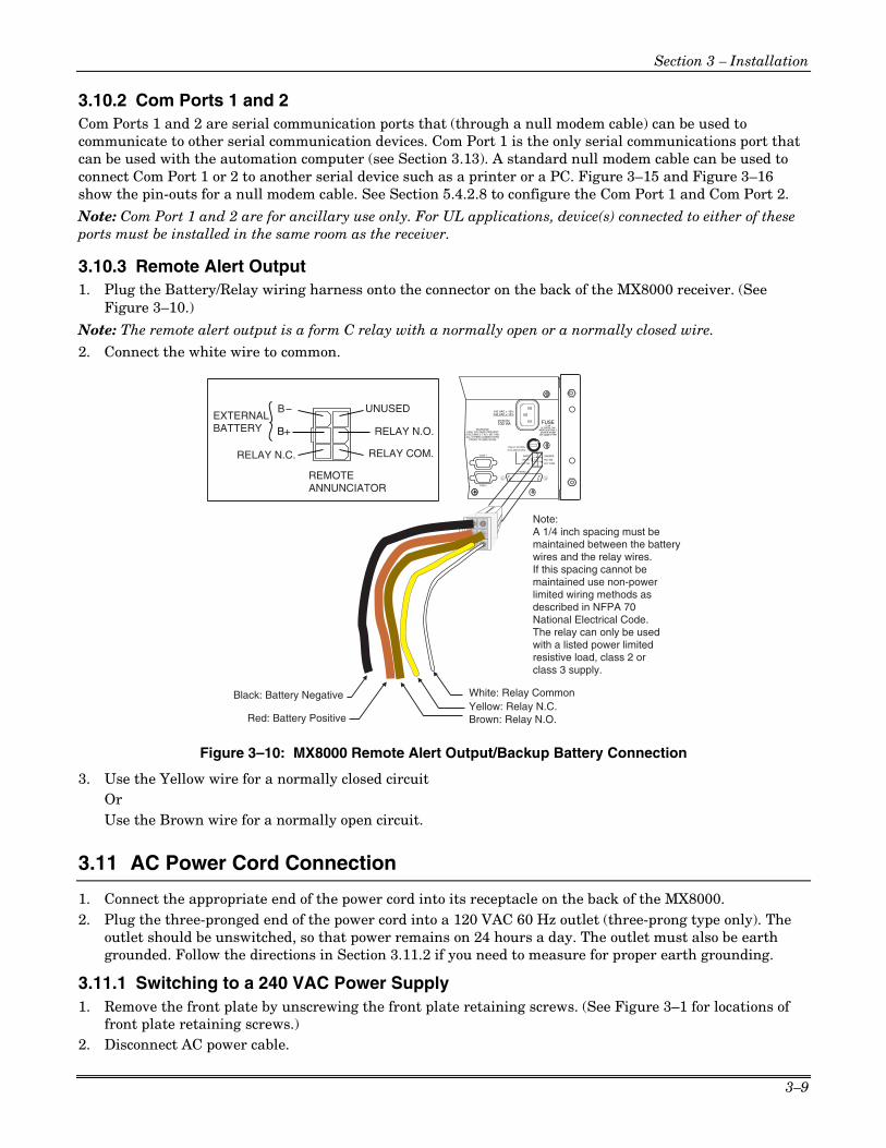
Section 3 – Installation
3–9
3.10.2 Com Ports 1 and 2 Com Ports 1 and 2 are serial communication ports that (through a null modem cable) can be used to communicate to other serial communication devices. Com Port 1 is the only serial communications port that can be used with the automation computer (see Section 3.13). A standard null modem cable can be used to connect Com Port 1 or 2 to another serial device such as a printer or a PC. Figure 3–15 and Figure 3–16 show the pin-outs for a null modem cable. See Section 5.4.2.8 to configure the Com Port 1 and Com Port 2.
Note: Com Port 1 and 2 are for ancillary use only. For UL applications, device(s) connected to either of these ports must be installed in the same room as the receiver.
3.10.3 Remote Alert Output 1. Plug the Battery/Relay wiring harness onto the connector on the back of the MX8000 receiver. (See
Figure 3–10.)
Note: The remote alert output is a form C relay with a normally open or a normally closed wire.
2. Connect the white wire to common.
COM 1
PARALLEL
100 VA
120 VAC ± 10%240 VAC ± 10%
50-60 Hz
WARNING!HIGH VOLTAGE PRESENT
DISCONNECT AC LINE ANDALL OTHER CONNECTORS
PROIR TO SERVICING
FUSE2.5A
SLOW BLOWREPLACE ONLY
WITH A FUSEOF SAME TYPE
UNUSED
RLY NO
RLY COM
BATT-
BATT+
RLY NC
COM 2
RELAY RATING2.5A 48VAC/VDC
White: Relay Common
Brown: Relay N.O.
Black: Battery Negative
Red: Battery PositiveYellow: Relay N.C.
B
RELAY N.C.
REMOTEANNUNCIATOR
RELAY COM.
RELAY N.O.
EXTERNALBATTERY B+
Note:A 1/4 inch spacing must bemaintained between the batterywires and the relay wires.If this spacing cannot bemaintained use non-powerlimited wiring methods as described in NFPA 70National Electrical Code.The relay can only be used with a listed power limitedresistive load, class 2 orclass 3 supply.
UNUSED
Figure 3–10: MX8000 Remote Alert Output/Backup Battery Connection
3. Use the Yellow wire for a normally closed circuit Or Use the Brown wire for a normally open circuit.
3.11 AC Power Cord Connection
1. Connect the appropriate end of the power cord into its receptacle on the back of the MX8000. 2. Plug the three-pronged end of the power cord into a 120 VAC 60 Hz outlet (three-prong type only). The
outlet should be unswitched, so that power remains on 24 hours a day. The outlet must also be earth grounded. Follow the directions in Section 3.11.2 if you need to measure for proper earth grounding.
3.11.1 Switching to a 240 VAC Power Supply 1. Remove the front plate by unscrewing the front plate retaining screws. (See Figure 3–1 for locations of
front plate retaining screws.) 2. Disconnect AC power cable.

MX8000 Installation and Operation Guide
3–10
3. Disconnect the backup battery. (See Figure 3–14.) 4. On the back of the receiver remove the four screws that hold the CPU, PS, User Interface Assembly to
the chassis. (See Figure 3–11 for screw locations.)
ScrewLocations
COM 1
PARALLEL
100 VA
120 VAC ± 10%240 VAC ± 10%
50-60 Hz
WARNING!HIGH VOLTAGE PRESENT
DISCONNECT AC LINE ANDALL OTHER CONNECTORS
PROIR TO SERVICING
FUSE2.5A
SLOW BLOWREPLACE ONLY
WITH A FUSEOF SAME TYPE
UNUSED
RLY NO
RLY COM
BATT-
BATT+
RLY NC
COM 2
RELAY RATING2.5A 48VAC/VDC
Figure 3–11: CPU, PS, User Interface Assembly Retaining Screw Locations
5. From the front of the receiver, pull the CPU, PS, User Interface Assembly out of the receiver chassis 6. Switch the power supply select switch to the up position. (See Figure 3–12.) 7. Slide the CPU, PS, User Interface Assembly back into the receiver chassis. 8. On the back of the receiver replace the four screws that hold the CPU, PS, User Interface Assembly in
place. (See Figure 3–11.)
115V
240V
Power SupplySelect Switch
PowerSupply
MotherBoard
FuseHolder
Power CordConnectorUser
Interface
Figure 3–12: Side View of CPU, PS, User Interface Assembly
9. Reconnect the AC power cable. 10. Reconnect the back-up battery. (See Figure 3–14.) 11. Replace the front plate by screwing in the front plate retaining screws. (See Figure 3–1.)
3.11.2 How to Verify Earth Ground To verify earth ground at the AC outlet the MX8000 receiver is powered from, use the following steps:
1. Measure the AC voltage between the center ground post and each side of the outlet (see A & B in Figure 3–13). You should read approximately 120 VAC at measurement point B and nominal VAC at measurement point A.
2. Measure the voltage between the two slotted holes. It should be equal to the voltage reading at measurement point B. (See Figure 3–13.) If these voltages are not equal, the outlet does not have a proper earth ground.
3. Ground the outlet by running a wire (18 gauge or higher) to a good earth ground.
The wire should be of equal or greater diameter to the wires used to feed the outlet. It may be necessary to have a licensed electrician ground the outlet.

Section 3 – Installation
3–11
LargerSlottedHole
GroundHole
SmallerSlottedHole
A
C
B
Figure 3–13: Outlet Voltage Measurement Points
3.12 Battery Connection
To install the backup battery, follow these steps:
Note: A UL approved 12VDC 7AH battery (such as a Powersonic 1270) will provide a minimum of 4 hours of battery backup power. (See 2.4.2 for UL requirements.)
1. Plug the Battery/Relay wiring harness onto the connector on the back of the MX8000 receiver. (See Figure 3–14.)
2. Connect the RED terminal to the positive (+) side of the battery.
3. Connect the BLACK terminal to the negative (-) side of the battery.
Note: Incorrect polarity can damage the battery and the MX8000.
Black: Battery Negative
Red: Battery Positive
Backup Battery
+-
COM 1
PARALLEL
100 VA
120 VAC ± 10%240 VAC ± 10%
50-60 Hz
WARNING!HIGH VOLTAGE PRESENT
DISCONNECT AC LINE ANDALL OTHER CONNECTORS
PROIR TO SERVICING
FUSE2.5A
SLOW BLOWREPLACE ONLY
WITH A FUSEOF SAME TYPE
UNUSED
RLY NO
RLY COM
BATT-
BATT+
RLY NC
COM 2
RELAY RATING2.5A 48VAC/VDC
Replace BatteryEvery 5 Years
Figure 3–14: Battery Connections

MX8000 Installation and Operation Guide
3–12
3.13 Automation Computer Connection
An automation computer can be connected to Com Port 1 on the MX8000 receiver. Com Port 1 is a 9-pin DTE port. Refer to Section 8 for details on automation communication protocols. The diagrams below describe some of the cable options.
4 DTR
6 DSR
7 RTS
8 CTS
1 DCD
3 TXD
2 RXD
5 GND
DTR 20
DSR 6
RTS 4
CTS 5
DCD 8
TXD 2
RXD 3
GND 7
MX8000 9-PIN DTE 25-PIN DTE
Figure 3–15: 25-Pin Null Modem Cable Connection
4 DTR
6 DSR
7 RTS
8 CTS
1 DCD
3 TXD
2 RXD
5 GND
DTR 4
DSR 6
RTS 7
CTS 8
DCD 1
TXD 3
RXD 2
GND 5
MX8000 9-PIN DTE 9-PIN DTE
Figure 3–16: 9-Pin Null Modem Cable Connection
3.13.1 Computer Port Baud Rate Selection The computer port baud rate is selectable from 110 to 38400 (See Section 5 – Programming)
3.14 Master/Slave Receiver Linking
The SBUS connector on the receiver can be used to link up to 3 receivers outputting to one automation computer and/or printer depending on the Master/Slave configuration. When this configuration is used, 1 receiver is set up as a master and remaining receivers are set up as slaves. The linking feature can decrease the number of serial ports required on the automation computer and/or the quantity of dot matrix printers used for automation backup. When using this feature, if the automation computer goes down, the information normally sent to the automation computer is output to the automation backup printer preceded by the receiver number that the information is coming from.
3.14.1 Receiver Linking Cabling Connections To use master/slave receiver linking, connect the receivers as shown in Figure 3–17 for linking to a printer or to both a printer and automation computer. If linking to only one slave receiver, simply omit the cable

Section 3 – Installation
3–13
that is not required. The cabling used is standard 4-wire RJ-11 cables (see Figure 3–18) for the interconnection of the receivers, a standard 25 pin printer cable as described in Section 3.10 and 3.10.1, and a DTE cable for the automation computer connection as described in Section 3.13. See Section 3.14.2 for Master/Slave Linking Programming Procedures. Notes: • For FM installations, the printer or any automation system connection must be within 20 ft. (6m) of the
MX8000 and in the same room as the MX8000. The Okidata Microline 320 is the only FM approved printer for use with the MX8000.
• If necessary (in non-FM installations), a serial printer can be used as the automation backup printer. In that situation, connect the serial cable from the COM2 port of the Master Receiver to the printer and omit the parallel printer connection.
3.14.2 Master/Slave Linking Programming The receivers may be programmed for master/slave linking to report to an automation computer and/or printer. The receivers must be programmed for master/slave linking on power-up when this feature is used. To perform linking programming, see 3.14.2.1 Master Printer/Slave Printer Linking Programming or 3.14.2.2 Master Automation/Slave Automation Linking Programming below.
Note: If it is desired to use linking for both the automation computer and printer, perform the procedures in 3.14.2.2 Master Automation/Slave Automation Linking Programming below. Printer linking will automatically be in effect when these procedures are performed.
00-M
X80
00-0
04-V
0
PRINTER
SLAVE MASTERSLAVE
NOTELIMIT TO ONE MASTER AND TWO SLAVES.
RJ-11(TYP.)
AUTOMATIONCOMPUTER
COM 1
PARALLEL
100 VA
120 VAC ± 10%240 VAC ± 10%
50-60 Hz
WARNING!HIGH VOLTAGE PRESENT
DISCONNECT AC LINE ANDALL OTHER CONNECTORS
PROIR TO SERVICING
SBUS
FUSE2.5A
SLOW BLOWREPLACE ONLY
WITH A FUSEOF SAME TYPE
UNUSED
RLY NO
RLY COM
BATT-
BATT+
RLY NC
COM 2
RELAY RATING2.5A 48VAC/VDC
COM 1
PARALLEL
100 VA
120 VAC ± 10%240 VAC ± 10%
50-60 Hz
WARNING!HIGH VOLTAGE PRESENT
DISCONNECT AC LINE ANDALL OTHER CONNECTORS
PROIR TO SERVICING
SBUS
FUSE2.5A
SLOW BLOWREPLACE ONLY
WITH A FUSEOF SAME TYPE
UNUSED
RLY NO
RLY COM
BATT-
BATT+
RLY NC
COM 2
RELAY RATING2.5A 48VAC/VDC
COM 1
PARALLEL
100 VA
120 VAC ± 10%240 VAC ± 10%
50-60 Hz
WARNING!HIGH VOLTAGE PRESENT
DISCONNECT AC LINE ANDALL OTHER CONNECTORS
PROIR TO SERVICING
SBUS
FUSE2.5A
SLOW BLOWREPLACE ONLY
WITH A FUSEOF SAME TYPE
UNUSED
RLY NO
RLY COM
BATT-
BATT+
RLY NC
COM 2
RELAY RATING2.5A 48VAC/VDC
PRINTER
SLAVE MASTERSLAVE
RJ-11(TYP.)
COM 1
PARALLEL
100 VA
120 VAC ± 10%240 VAC ± 10%
50-60 Hz
WARNING!HIGH VOLTAGE PRESENT
DISCONNECT AC LINE ANDALL OTHER CONNECTORS
PROIR TO SERVICING
SBUS
FUSE2.5A
SLOW BLOWREPLACE ONLY
WITH A FUSEOF SAME TYPE
UNUSED
RLY NO
RLY COM
BATT-
BATT+
RLY NC
COM 2
RELAY RATING2.5A 48VAC/VDC
COM 1
PARALLEL
100 VA
120 VAC ± 10%240 VAC ± 10%
50-60 Hz
WARNING!HIGH VOLTAGE PRESENT
DISCONNECT AC LINE ANDALL OTHER CONNECTORS
PROIR TO SERVICING
SBUS
FUSE2.5A
SLOW BLOWREPLACE ONLY
WITH A FUSEOF SAME TYPE
UNUSED
RLY NO
RLY COM
BATT-
BATT+
RLY NC
COM 2
RELAY RATING2.5A 48VAC/VDC
COM 1
PARALLEL
100 VA
120 VAC ± 10%240 VAC ± 10%
50-60 Hz
WARNING!HIGH VOLTAGE PRESENT
DISCONNECT AC LINE ANDALL OTHER CONNECTORS
PROIR TO SERVICING
SBUS
FUSE2.5A
SLOW BLOWREPLACE ONLY
WITH A FUSEOF SAME TYPE
UNUSED
RLY NO
RLY COM
BATT-
BATT+
RLY NC
COM 2
RELAY RATING2.5A 48VAC/VDC
AUTOMATIONCOMPUTER PORT 1
AUTOMATIONCOMPUTER PORT 2
AUTOMATIONCOMPUTER PORT 3
Master Printer/Slave Printer Linking
Master Automation/Slave Automation Linking
Figure 3–17: MX8000 Master/Slave Receiver Linking Cabling Connections

MX8000 Installation and Operation Guide
3–14
00-MX8000-005-V0
2 3 4 5 615 4 3 2 16
LOCK/UNLOCKTAB DOWN
LOCK/UNLOCKTAB UP
BLACK
RED
GREEN
YELLOW
RJ-11CONNECTORS
Figure 3–18: SBUS Receiver Linking Cable
3.14.2.1 Master Printer/Slave Printer Linking Programming To perform MasterPrn/SlavePrn Linking Programming, follow these steps:
1. Verify that all SBUS connections have been made as described in Section 3.14.1 and shown in Figure 3–17.
2. Program the Master (MstrPrn) Receiver as follows: a. Power up the Master Receiver and allow the Line Cards to be initialized.
b. From the “Installer/Program Menu/General Options” display, select “1 Operation Mode” and configure for “Automatic.”
c. From the “3 Communications” display, select “1 Port Functions” and configure COM1 for “Automation” and parallel port for “Auto Bkp Prn.” Note: If a serial printer is being used as a automation backup printer, configure COM2 as the “Auto Bkp Prn” instead of the parallel port.
d. From “4 System Options” select “MstrPrn” and set appropriate “Rcvr ID.” e. From “6 Slave List” enter a unique Slave number for each slave receiver. f. Exit the programming mode and cycle power on the Master Receiver for the new settings to take
effect.
3. Program the Slave (SlvPrn) Receiver as follows: a. Power up the Slave Receiver and allow the Line Cards to be initialized. b. From the “Installer/Program Menu/General Options” display, select “1 Operation Mode” and
configure for “Automatic.”
c. From the “3 Communications” display, select “1 Port Functions” and configure COM1 for “Automation.”
d. From “4 System Options” select verify “SlvPrn” setting and set appropriate “Rcvr ID.” matching the number programmed in the Master Receiver.
e. Exit the programming mode. f. Repeat a. through e. on the second Slave Receiver, if being used.
3.14.2.2 Master Automation/Slave Automation Linking Programming To perform MasterAuto/SlaveAuto Linking Programming, follow these steps:
1. Program the Master (MstrAuto) Receiver as follows: a. Power up the Master Receiver and allow the Line Cards to be initialized. b. From the “Installer/Program Menu/General Options” display, select “1 Operation Mode” and
configure for “Automatic.”

Section 3 – Installation
3–15
c. From the “3 Communications” display, select “1 Port Functions” and configure COM1 for “Automation” and parallel port for “Auto Bkp Prn.” Note: If a serial printer is being used as a automation backup printer, congigure COM2 as the “Auto Bkp Prn” instead of the parallel port.
d. From “4 System Options” select “MstrAuto” and set appropriate “Rcvr ID.”
e. From “6 Slave List” enter a unique Slave number for each slave receiver. f. Exit the programming mode and cycle power on the Master Receiver for the new settings to take
effect. 2. Program the Slave (SlvAuto) Receiver as follows:
a. Power up the Slave Receiver and allow the Line Cards to be initialized. b. From the “Installer/Program Menu/General Options” display, select “1 Operation Mode” and
configure for “Automatic.” c. From “4 System Options” select verify “SlvAuto” setting and set appropriate “Rcvr ID.” matching the
number programmed in the Master Receiver. d. Exit the programming mode. e. Repeat a. through d. on the second Slave Receiver, if being used.
3. Using 4-pin RJ-11 cables, connect a cable from the Master Receiver to the first Slave Receiver and then connect a second cable from the first Slave Receiver to the second Slave Receiver.

MX8000 Installation and Operation Guide
3–16

4–1
Section 4 Operation
This section covers information on how to operate the MX8000 Receiver.
4.1 Touchpad Function Buttons
The front panel of the MX8000 is made up of; a touchpad, containing numbers, arrows and buttons; a VFD display; and an array of LED indicators. (See Figure 4–1.)
HOME HANGUP
CALL
PENDING
OPERATOR
LOGGED IN
SYSTEM
FAULT
SYSTEM
POWER
LISTEN
PREV
CALL
NEXT EVENT
NEXT
CALL
0
1 2
#
3
654
7 8 9
PREV EVENT
ACK
ENTER
MENU
31
32
33
34
35
36
28
29
30
22
23
24
25
26
27
19
20
21
13
14
15
16
17
18
10
11
12
4
5
6
7
8
9
1
2
3
LOG
STATUS
8765 12111094321
DEVICE
LEDDisplays
TouchpadKeys
VFD Display
Figure 4–1: MX8000 Front Panel
The touchpad on the MX8000 Receiver is used in all operating modes (normal and programming mode).
00-M
X80
00-0
02-V
0
HOME HANGUP
CALLPENDING
OPERATORLOGGED IN
SYSTEMFAULT
SYSTEMPOWER
LISTEN
PREVCALL
NEXT EVENT
NEXTCALL
0
1 2
#
3
654
7 8 9
PREV EVENT
ACK
ENTERMENU
1
2
3
LOGSTATUS
1
Figure 4–2: Touchpad Layout

MX8000 Installation and Operation Guide
4–2
Table 4–1 displays each individual touchpad key and describes its function in each operating mode.
Table 4–1: Touchpad Buttons Description
Operating Mode Key Name
Normal Programming
Up Arrow Display previous item in the Call History or System History.
Go back to previous choice or character.
Down Arrow Display next item in the Call History or System History.
Move to next choice or character.
Left Arrow Display previous item in the Call History. Exits System History.
Exit the current menu. Move to previous programming field.
Right Arrow Display next item in the Call History. Not used in System History
Select menu item indicated by equal sign (see Figure 4–5). Move to next programming field.
ENTER MENU
Enter/Menu Button Bring up Main Menu. Select menu item indicated by equal sign (see Figure 4–5). Enter chosen parameter.
ACK Acknowledge Button Manually Acknowledge a call or event. (Used only if receiver is in manual mode.)
Used in log mode to acknowledge and silence system troubles.
LOG STATUS
Log Button Pressed to log on or off the system. Pressed to view system status messages.
N/A
1 – 9 Digit Keys Used to enter numeric inputs. Numeric input, option selection.
HOME
✶✶✶✶ Star or Home Key Will return display to the oldest
unacknowledged event. Enters a * Character when programming in an “Edit” field. See Table 5–1 for Types of Programming Fields, descriptions.
HANGUP
0 0 or Hangup key In manual mode the 0/ hangup key is
used to hangup line card when the listen feature was activated, or to end a runaway call from a panel.
Used to enter numeric inputs.
LISTEN
# Pound Key or Listen Key
In manual mode this key is used to initiate the listen in feature.
Enters a # Character when programming in an “Edit” field. See Table 5–1 for Types of Programming Fields, descriptions.
4.2 Displays
This section describes the two types of displays that the MX8000 receiver uses.

Section 4 – Operation
4–3
4.2.1 LED Displays
Table 4–2: LED Description
Meaning LED
On Off Flashing
System Power System power is on. No AC or DC power to the Receiver
No AC power and the system is operating on the backup battery.
System Fault A fault condition exists that has been acknowledged but not cleared.
The system is operating normally.
A fault condition exists that has not been acknowledged.
Operator Logged In An operator is logged on. No operator is logged on.
Touchpad LEDs
Call Pending The acknowledge key was pressed at least once, but not all the events in a call were acknowledged.
No calls pending or all calls have been acknowledged.
Calls pending.
Off The line card is operating normally.
Red Slow Flash – Uninitialized. Fast Flash – Trouble (Specifics available on VFD).
Line Port LED (MX8000-LC3
and MX8000-LRR)
Green Off Hook Ring Detection – Flash follows ring. Listen-in – 1 sec. on, 1 sec off.
Red (Fault) N/A The line card is operating normally.
Slow Flash – Uninitialized. Fast Flash – Trouble (Specifics available on VFD).
Green (Active) Off Hook No activity. Ring Detection – Flash follows ring.
Line Port LEDs (MX8000-LC1)
Yellow (Listen-in) Comes on when operator acknowledges the listen-in call.
No listen-in occurring. N/A
4.2.2 VFD Status Display The status display is a 4-line 20 character (each line) backlit VFD that shows the various alarm and function messages. It functions in all modes of operation (normal and programming mode). As the MX8000 acknowledges calls and messages, it updates the calls on the VFD and silences the alert tone.
MX8000 Receiver AdemcoMan: Active01/01/01 08:32:44
Figure 4–3: VFD Display
4.2.2.1 VFD Abbreviations Many of the words used on the VFD are abbreviated to accommodate 20 characters per line. Table 4–3 compares the event that is reported to how it is output to the VFD and printer.

MX8000 Installation and Operation Guide
4–4
Table 4–3: VFD and Printer Abbreviations
Event VFD Printer
Alarm Alrm Alarm
Trouble Trbl Trouble
Restore Rstr Restore
Supervisory Sprv Superv
Opening Open Opening
Closing Clos Close
Remote Rmot Remote
Disable Dsbl Disable
Bypass Byps Bypass
Unbypass Ubyp Unbypass
Test Test Test
Listen-in Lstn Listen
System Sytm System
Access Accs Access
Report Rprt Report
Cancel Cncl Cancel
Zone Number Z# Zone
Door Number D# Door
User Number Us# User
Area Number A# Area
4.3 Initial System Power Up
Apply power to the MX8000 by plugging in the AC power cable. (See Figure 3–3.) When the MX8000 powers up, the display will go through the routine shown in Figure 4–4.
Powerup ScreenSelf Test
123123C 11/13/00Internal Keypad
MX8000 Receiver Ademco
Normal OperationLine Card Initialization(No Events)Lines 1&2 Model and Manufacturer bannerLine 3 System StatusLine 4 Date and Time
MX8000 Receiver AdemcoMan: Active04/02/02 09:43:46AM
MX8000 Receiver AdemcoMan: Active<Initializing...>Receiver cycles
between these displays until initializationis complete
Figure 4–4: Power-up Routine
The system defaults in the manual operation. To select automatic operation see Section 5.4.1.1.
Note: Any time the power is removed from the receiver (line and battery), the time and date will have to be reprogrammed on power-up.
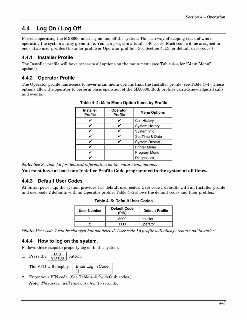
Section 4 – Operation
4–5
4.4 Log On / Log Off
Persons operating the MX8000 must log on and off the system. This is a way of keeping track of who is operating the system at any given time. You can program a total of 40 codes. Each code will be assigned to one of two user profiles (Installer profile or Operator profile). (See Section 4.4.3 for default user codes.)
4.4.1 Installer Profile The Installer profile will have access to all options on the main menu (see Table 4–4 for “Main Menu” options).
4.4.2 Operator Profile The Operator profile has access to fewer main menu options than the Installer profile (see Table 4–4). These options allow the operator to perform basic operation of the MX8000. Both profiles can acknowledge all calls and events.
Table 4–4: Main Menu Option Items by Profile
Installer Profile
Operator Profile
Menu Options
✔ ✔ Call History ✔ ✔ System History ✔ ✔ System Info ✔ ✔ Set Time & Date ✔ ✔ System Restart ✔ Printer Menu ✔ Program Menu ✔ Diagnostics
Note: See Section 4.6 for detailed information on the main menu options.
You must have at least one Installer Profile Code programmed in the system at all times.
4.4.3 Default User Codes At initial power up, the system provides two default user codes. User code 1 defaults with an Installer profile and user code 2 defaults with an Operator profile. Table 4–5 shows the default codes and their profiles.
Table 4–5: Default User Codes
User Number Default Code (PIN)
Default Profile
*1 8000 Installer
2 1111 Operator
*Note: User code 1 can be changed but not deleted. User code 1’s profile will always remain as “installer”.
4.4.4 How to log on the system. Follows these steps to properly log on to the system:
1. Press the LOG STATUS button.
The VFD will display Enter Log In Code:[ ]
2. Enter your PIN code. (See Table 4–5 for default codes.)
Note: This screen will time out after 15 seconds.

MX8000 Installation and Operation Guide
4–6
3. Press the ENTER MENU button.
If the correct PIN is entered the VFD will display Logged in asInstaller # XXUser Name.
The “Operator Logged In” LED will also turn on.
If an invalid code is entered the VFD will display Access code not verified.
Note: If the previous user has not logged off, a new user can still log on by entering a PIN code. This will automatically log off the previous user and log in the new user.
4.4.5 How to log off the system. Follows these steps to properly log off the system:
1. Press the LOG STATUS button.
The VFD will display #nn User Name Log Out [ ]
Note: This screen will time out after 15 seconds.
2. Enter your PIN code. (See Table 4–5 for default codes.)
3. Press the ENTER MENU button.
If the correct PIN is entered the VFD will display User Name Logged out . The “Operator Logged In” LED will also turn off.
If an invalid code is entered the VFD will display Access code not verified.
4.5 Modes of Operation
This section describes the different modes of operation for the MX8000 Receiver (normal mode and programming mode) and the options available in them.
4.5.1 Normal Mode Normal mode consists of three options, one if the receiver is intended to be used with an automation system, one for manual operation, and one to just log the events without manual acknowledgments or automation communication.
4.5.1.1 Manual Operation Requires a manual acknowledgment of each call or event from an operator.
How to Manually Acknowledge Calls:
When the call pending LED is flashing and the on-board annunciator is beeping:
1. Press the ACK button to acknowledge the call.
2. Repeat step 1 until all calls are acknowledged and the display shows No More Data.
4.5.1.2 Automatic Operation Event information is sent directly to the automation computer.
Note: If the automation system fails, the receiver will automatically switch to manual mode in less than 30 seconds. The switching time is twice the value set in Ack Timeout (See Table 5–5). The receiver will return to automatic mode after communication to the automation computer is restored.

Section 4 – Operation
4–7
4.5.1.3 Log Only Log only mode will log event data without manual acknowledgments or communications with the automation computer. All event information is intended for printer output.
Notes:
•••• On initial power-up the receiver will default in manual operation. The receiver can be set to automatic or log only operation in program mode (see Section 5.4.1).
• The log only mode must not be used for UL installations.
4.5.2 Program Mode In program mode all general, line card, and user profile options can be changed. See Section 5 – Programming for more detailed information on programming the receiver or refer to the Quick Chart, (Table A–1) for programming overview.
Note: The receiver will process calls while in the program mode.
4.6 Main Menu
This section gives detailed information about the items available in the Installer/operator menu options, which this manual will refer to as the main menu. The menu items available to each logged on user is dependent on the profile assigned to that user (see Table 4–4 for menu items for each profile). The user profile is assigned to each user through programming (see Section 5.6 for programming user profiles).
4.6.1 How to Display the Main Menu Once a user has logged on to the system (see Section 4.4.4), follow these steps to view the main menu options:
1. Press the ENTER MENU button.
The VFD display will show the main menu options.
<Operator Menu>1=Call History2 System History3 System Info
<Operator Menu>4=Set Time & Date5 System Restart< Exit Menu
Down Arrowindicates additionalmenu items
Equal sign indicatesthe item that will bechosen if enter key orright arrow is pressed
The profile assignedto the user will appearin display title as eitherOperator or Installer
Indicates that pressing aleft arrow will exit Main Menu
Display afterDown Arrowpressed 3 times
Option 5 is anon-editable field
¯
Figure 4–5: Main Menu Display
Note: The main menu display will remain visible for 15 minutes of idle time after which it will revert back to the manual or automatic display window. See Figure 4–3.
2. Choose the desired menu item. (See Figure 4–6.)

MX8000 Installation and Operation Guide
4–8
4.6.2 How to Maneuver Through Main Menu Figure 4–6 indicates what keys on the touchpad are used to maneuver through the Main Menu.
Menu Controls
1
To accept amenu item press
Or press
Or press thenumber keycorrespondingto the desiredmenu option
To Choose the nextmenu item press
Go back toprevious choice
Exit current menuor menu item. Move back to previousentry.
ENTERMENU
Number can alsobe used to enternumeric informationwhere needed
Figure 4–6: Main Menu Controls
4.6.3 Call History Call history displays the calls that are in the history buffer.
010083-01 #12345TrblZ# 4201/01 10:26P *E1/1
Event ReferenceNo. (0001-9999)
Reason for Call
Zone Number
Month & DayTime Star indicates that
the call was acknowledged
Number and orderof events for thisreport.
Account Number(Up to Ten Digits)
Line Port No.
Programmable 2-Digit Receiver No.
Figure 4–7: View of a Call History Screen
To display a specific event enter the reference number then press the ENTER MENU . Press the ✶✶✶✶ to go to most
recent call. See Table 4–3 for display abbreviations.

Section 4 – Operation
4–9
4.6.4 System History System history displays any events that are stored in the history buffer. System events are any events related to the receiver operation such as line card faults, low backup battery, AC power loss, log in, log out, system program change, communication failure to a printer or automation system, etc.
Note: Up arrow moves back to the previous event that occurred.
To display a specific event enter the event number (see Figure 4–8) then
press the ENTER MENU . Press the ✶✶✶✶ to
go to most recent call.
<Installer Menu>2=System History3 System Info4 Set Time & Date
SysEvent 22 of 22User Log In#1102/03/01 09:56AM
SysEvent 21 of 22User Log Out#0202/03/01 09:56AM
¯
Event Number
View after2 pressed
Up arrowdisplays previousevent
2
Figure 4–8: System History Display Sequence
4.6.5 System Info System Info is a non-editable screen that displays the model number, the software revision, software date code, and receiver ID number. If a down arrow is pressed, the display will sequentially show the line card firmware information, which includes the firmware part number, the software date, and letter revision. The first line card firmware information display is for a MX8000–LC1 card, the second display is for a MX8000–LC3 card, and the third display is for a MX8000–LRR card.
Model:Version: Date:
Rcvr ID: ¯
LineCard Firmware:124047Date: 10/18/97 Rev: G ¯
Version NumberModel Number
Date Code
LineCard Firmware:124062Date: 12/10/01 Rev: A ¯
LineCard Firmware:124061Date: 4/02/02 Rev: B ¯
MX8000XX.XXMMM D 200201
Letter Rev.Date
Firmware Part NumberMX8000-LC1
MX8000-LRR
MX8000-LC3
Figure 4–9: System Information Display
4.6.6 Set Time & Date If Set Time & Date, is selected the operator can change the time and date currently displayed on the receiver. (See Figure 4–10 for setting time and date procedure.)
Note: If you make an error while setting the time and/or date, press and re-enter the correct value.
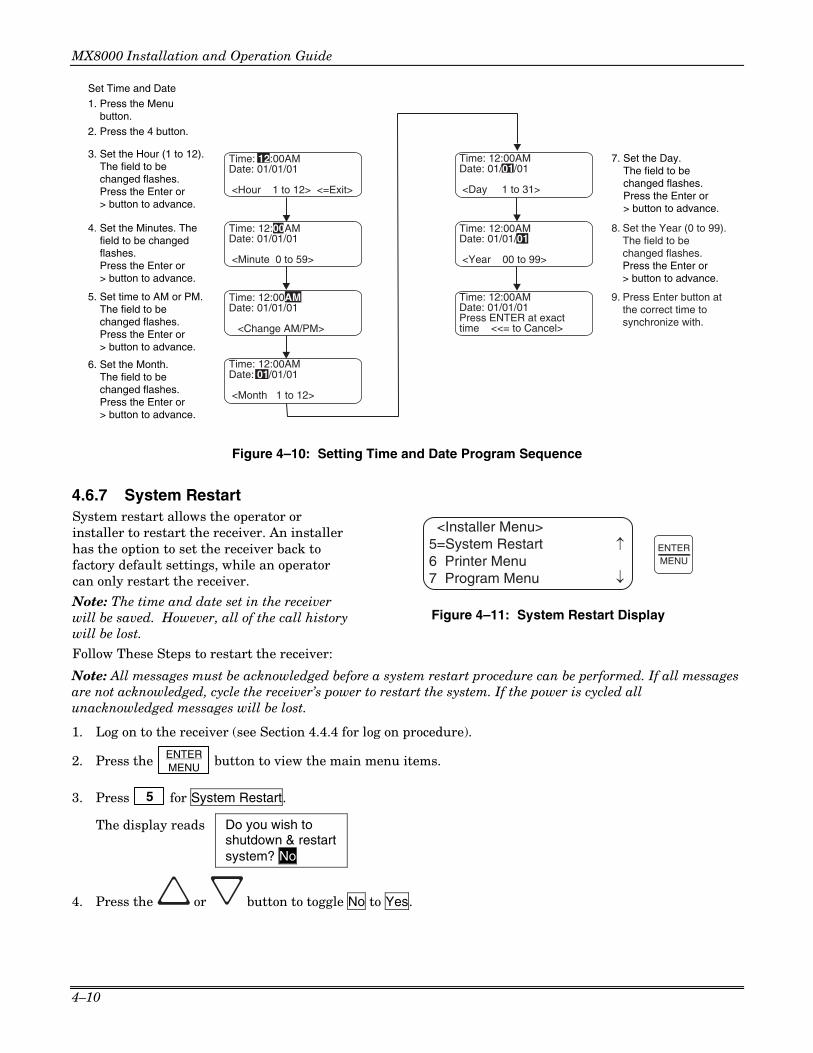
MX8000 Installation and Operation Guide
4–10
Date: 01/01/01
<Minute 0 to 59>
Date: 01/01/01
<Change AM/PM>
Time: 12:00AM
<Month 1 to 12>
Set Time and Date
1. Press the Menubutton.
2. Press the 4 button.
3. Set the Hour (1 to 12).The field to bechanged flashes.Press the Enter or> button to advance.
4. Set the Minutes. Thefield to be changedflashes.Press the Enter or> button to advance.
5. Set time to AM or PM.The field to bechanged flashes.Press the Enter or> button to advance.
6. Set the Month.The field to be changed flashes.Press the Enter or> button to advance.
7. Set the Day.The field to be changed flashes.Press the Enter or > button to advance.
8. Set the Year (0 to 99).The field to bechanged flashes.Press the Enter or > button to advance.
Press Enter button atthe correct time tosynchronize with.
Date: 01/01/01
<Hour 1 to 12> <=Exit>
Time: 12:00AMDate: 01/01/01Press ENTER at exacttime <<= to Cancel>
9.
Time: 12:00AM
Time: 12:00AM
Time: 12:00AM
Date: 01/01/01
Time: 12:00AM
<Year 00 to 99>
Date: 01/01/01
Time: 12:00AM
<Day 1 to 31>
Date: 01/01/01
Figure 4–10: Setting Time and Date Program Sequence
4.6.7 System Restart System restart allows the operator or installer to restart the receiver. An installer has the option to set the receiver back to factory default settings, while an operator can only restart the receiver.
Note: The time and date set in the receiver will be saved. However, all of the call history will be lost.
Follow These Steps to restart the receiver:
<Installer Menu>5=System Restart6 Printer Menu7 Program Menu ¯
ENTERMENU
Figure 4–11: System Restart Display
Note: All messages must be acknowledged before a system restart procedure can be performed. If all messages are not acknowledged, cycle the receiver’s power to restart the system. If the power is cycled all unacknowledged messages will be lost.
1. Log on to the receiver (see Section 4.4.4 for log on procedure).
2. Press the ENTER MENU button to view the main menu items.
3. Press 5 for System Restart.
The display reads Do you wish to shutdown & restart system? No
4. Press the or button to toggle No to Yes.

Section 4 – Operation
4–11
5. Press ENTER MENU . Users with an operator profile are done at this point.
The display reads Do you wish to set to factory default settings? No
Note: This display will only appear if the logged on User has an Installer Profile (see section 4.4.1).
6. Press the or button to toggle No to Yes.
Note: If you choose Yes all line card and user custom programming will be lost.
4.6.8 Printer Menu In the print menu you can print customized reports by the type of alarm, edit the desired print output, and configure output for your printer.
<Installer Menu>6=Printer Menu7 Program Menu8 Diagnostics
<Printer Menu>1=Print Report2 Edit Evnt Format3 Config Printer
¯
6
Figure 4–12: Print Menu Items
Table 4–6: Printer Menu Choices
Printer Menu Choice 1 Choice 2 Comments Priority 1 (Life safety signals-Fire, Duress) Priority 2 (Property safety signals-Burg.) Priority 3 (Supervisory signals) Priority 4 (Trouble signals)
Call History
Priority 5 (All other signals)
Y Indicates that this item will print on this report. N Indicates that this item will not print on this
report. The call History print will execute once you exit from “Choice 2”. Note: Choice 2 settings are not retained in flash memory and have to be chosen for each call history printing.
System History This option prints all the system events in the event history buffer.
Print All Print all of the system and line card data described below under Program Data and Line Card #.
Program Data Print just the systems programmed data such as Operating Mode, Display Options, Communication Definitions, System Options, and Message Queue Options.
Users List Print a list of assigned MX8000 Users with their Level (Installer or Operator) and PIN Number.
System Config
Line Card # Print line card configurations per line card. These are the items programmed using the Line Card Menus.
Test Page Print a test page.
Print Report
Line Card Statistics
Print line card statistics which include the device number, serial number, part number, physical line number, virtual receiver and line numbers, total calls for the line, calls today, and number of bad calls for the line.

MX8000 Installation and Operation Guide
4–12
Table 4–6: Printer Menu Choices (cont’d)
Printer Menu Choice 1 Choice 2 Comments
Date/Time Y or N Format Type Y or N Ref Number Y or N Call Sep Y or N Device Num Y or N
Edit Evnt Format
Prt Condensed Y or N
Y Indicates that this item will print on a report. N Indicates that this item will not print on a
report. Default setting is Y for all edit event format options. These settings are saved to flash memory.
Line Terminator
CR or CRLF CR = Carriage return. CRLF = Carriage return and Line feed.
Offline Time 0 - 60 seconds Offline time is how long the receiver will wait before giving a trouble indication after communication is lost with the printer. The default setting is 2 seconds. (30 second maximum for UL applications.)
Config Printer
Switch Delay Time
0 - 60 seconds Switch delay time is the duration the receiver will wait before switching to the backup printer after communication is lost with the primary printer. The default setting is 20 seconds.
4.6.8.1 Print Report
<Printer Menu>1=Print Report2 Edit Evnt Format3 Config Printer
<Print Report>1=Call History2 System History3 System Config
<Print Report>4 Test Page
< Exit menu
¯
¯
1
5=LC Statistics
Figure 4–13: Print Report Menu Items
Through the print report option you can choose to print the call history, system history, system configuration information, or just print a test page.
How to Print Call History
Follow these steps to print the call history: 1. Log on to the receiver (see Section 4.4.4 for log on
procedure).
2. Press the ENTER MENU button to view the main menu
items.
3. Press 6 for the printer menu. (See Figure 4–12.)
4. Press 1 for print report menu. (See Figure 4–13.)
5. Press 1 for call history options.
6. Press the or button to move through the call history menu choices. See Figure 4–14.
7. When the equal sign highlights the call history items
you desire to print for this report press ENTER MENU or
to toggle the setting between Y (yes print) or N (don’t print).
8. Press to exit menu.
<Call History>01=Priority #1 [Y]02 Priority #2 [Y]03 Priority #3 [Y]
<Call History>04=Priority #4 [Y]05 Priority #5 [Y]< Exit Menu
¯
ENTERMENU
Figure 4–14: Call History Options
How to Print System History Follow these steps to print the system history: 1. Log on to the receiver (see Section 4.4.4 for log on procedure).

Section 4 – Operation
4–13
2. Press the ENTER MENU button to view the main menu items.
3. Press 6 for the printer menu. (See Figure 4–12.)
4. Press 1 for print report menu. (See Figure 4–13.)
5. Press 2 to print the system history.
6. Press to exit menu.
How to Print System Configuration Follow these steps to print the system configuration: 1. Log on to the receiver (see Section 4.4.4 for log on
procedure).
2. Press the ENTER MENU button to view the main menu
items.
3. Press 6 for the printer menu. (See Figure 4–
12.)
4. Press 1 for print report menu. (See Figure 4–
13.)
5. Press 3 to view system configuration options.
See Figure 4–15.
6. Press the or button to move through the system configuration print choices.
<Print Report>3=System Config4 Test Page5 LC Statistics
<System Config>04=Line Card # 1[N]05 Line Card # 2[N]06 Line Card # 3[N]
<System Config>01=Print All [N]02 Program Data [N]03 Users List [N]
From item 04 down isa list of existing Line Cardnumbers.
¯
¯
¯
3
Figure 4–15: System Configuration Print Items
7. When the equal sign highlights an option press ENTER MENU or to toggle the setting between Y (yes
print) or N (don’t print).
8. Press to print the data and exit menu. Note: These choices are not saved to flash memory and will have to be chosen each time that print system configuration is entered.
How to Print a Test Page Follow these steps to print a test page: 1. Log on to the receiver (see Section 4.4.4 for log on procedure).
2. Press the ENTER MENU button to view the main menu items.
3. Press 6 for the printer menu. (See Figure 4–12.)
4. Press 1 for print report menu. (See Figure 4–13.)
5. Press 4 to print a test page.
6. Press to exit menu.

MX8000 Installation and Operation Guide
4–14
How to Print Line Card Statistics Follow these steps to print line card statistics: 1. Log on to the receiver (see Section 4.4.4 for log on procedure).
2. Press the ENTER MENU button to view the main menu items.
3. Press 6 for the printer menu. (See Figure 4–12.)
4. Press 1 for print report menu. (See Figure 4–13.)
5. Press 5 to print the statistics for all line cards.
6. Press to exit menu.
4.6.8.2 Edit Event Format Edit event format allows you to configure what information will print on reports to the receiver.
Follow these steps to configure the report format: 1. Log on to the receiver (see Section 4.4.4 for log on
procedure).
2. Press the ENTER MENU button to view the main menu
items.
3. Press 6 for the printer menu. (See Figure 4–12.)
4. Press 2 for event format menu items. (See Figure
4–16.)
¯
¯
<Event Format Menu:>01=Date/Time [Y]02 Format Type [Y]03 Ref Number [Y]
<Event Format Menu:>
04=Call Sep [Y]05 Device Num [Y]
<Event Format Menu:>
06 Prt Condensed[N]
05 Device Num [Y]06 Prt Condensed[N]< Exit Menu
Figure 4–16: Event Format Menu Items
5. Press the or button to move through the event format choices. (See Table 4–7 for choice definitions.)
Table 4–7: Event Format Choices and Meaning
Event Format Options
Choices Meaning
Y (Yes) Date/Time
N (No)
Y = Date and time will print for each report message to the printer. N = Date and time will not print for each report message to the printer.
Y (Yes)
Format Type
N (No)
Y = The reporting format type of the calling control panel will print for each report message to the printer.
N = The reporting format type of the calling control panel will not print for each report message to the printer.
Note: The Format Type will be listed as a number, which represents the format used for that communication.
Y (Yes) Reference Number N (No)
Y = The reference number will print for each report message to the printer. N = The reference number will not print for each report message to the printer. (See Figure 4–7)
Y (Yes) Call Separator
N (No)
Y = Print a dashed-line between each message report to the printer. N = Do not print a dashed-line between each message report to the printer.
Device Number Y (Yes) Y = Print the device number of the reporting message to the printer.
N = Do not print the device number of the reporting message to the printer.
N (No) Print Condensed Y (Yes)
N = Printer output in normal mode. Y = All print data on a single line.

Section 4 – Operation
4–15
EXAMPLE OF THE EVENT PRINTOUT For this example example, a yes answer was entered in the event format options for Date/Time, Format Type, Reference Number, Call Separator, and Device Number.
Example of Print in Normal Mode 05/25/2004 02:53:37PM Device #: 1-34 Format #: 50 Reference #: 62 Account #: 1000 [New] Restore-Fire Alarm ID# 001 Group# 01 R110 ------------------------- 05/25/2004 02:54:03PM Device #: 1-34 Format #: 50 Reference #: 64 Account #: 1000 [New] Restore-Fire Alarm ID# 001 Group# 01 R110 -------------------------
Example of Print in Condensed Mode 05/25/2004 02:53:37PM D#:1-34 F#:50 Ref#:62 A#: 1000 [New] Restore-Fire Alarm ID# 001 Group# 01 R110 ------------------------- 05/25/2004 02:54:03PM D#:1-34 F#:50 Ref#:64 A#: 1000 [New] Restore-Fire Alarm ID# 001 Group# 01 R110 ------------------------- ← ...................................................................Printer Margins ....................................................................... →In the above Condensed Print example: D# = Device Number, F# = Format Type Number, Ref# = Reference Number, A# = Account Number,
7. When the equal sign highlights each option press ENTER MENU or to toggle the setting between Y (yes
print) or N (don’t print).
Note: These settings are saved to flash memory.
8. Press to exit menu.
4.6.8.3 Configure Printer Depending on the printer you are using it may require that this be set to either carriage return or carriage return with a line feed.
Follow these steps to configure the printer: 1. Log on to the receiver (see Section 4.4.4 for log on procedure).
2. Press the ENTER MENU button to view the main menu items.
3. Press 6 for the printer menu. (See Figure 4–12.)
4. Press 3 for configure printer menu items.
The display will be flashing on the line terminator field.
5. Press the or button to toggle between CR or CRLF. (See Table 4–6.)
6. When the desired setting is flashing press ENTER MENU .
The display will now flash on the offline time field. 7. Enter the desired time (from 01-99 seconds), 30-second maximum in UL applications.
8. Press ENTER MENU .
The display will now flash on the switch delay time field.

MX8000 Installation and Operation Guide
4–16
9. Enter the desired time (from 01-99 seconds).
10. Press ENTER MENU .
11. Press to exit menu.
4.6.9 Program Menu If program is selected from the main menu the system will enter into “Program Mode”. (See Section 4.5 for information on modes of operation.) In program mode you can program all the general options, line card options, and user list. (See Appendix A, Table A–1 for Programming Quick Chart.)
<Program Menu>1=General Options2 Line Device Menu3 User List ¯
Figure 4–17: Program Menu Items
4.6.10 Diagnostics Menu The diagnostics menu items can be used while testing and troubleshooting the system.
<Diagnostics>4=Format-Raw Hex5 LC Debug Mode6 LC Statistics
<Diagnostics>7=Port Status< Exit Menu
<Diagnostics>1 Phantom Menu2 Message Que3 Event Log ¯
¯
8
Figure 4–18: Diagnostics Menu Items
4.6.10.1 Phantom Menu The phantom menu contains list of various communication format phantom signals (see Table 4–8) that can be used to test the receiver or automation software configurations. For example, you set a line cards parameters for a particular communications format and would now like to verify that this new configuration will communicate with other communication formats, you can send phantom signals in the formats you wish to test that line card with. To use the phantom menu to test a format: 1. Select Phantom Menu in the Diagnostics Menu. 2. Scroll through the list of formats and select the format to be tested. 3. Exit the Phantom Menu. Messages will be sent to the printer in the format selected.
Table 4–8: Phantom Signals Formats List
Choice Format Choice Format 01 DCS DCS 12 SIA D1 ADEMCO High Speed (SIA D1) 02 CID Contact ID® 03 ITI ITI format
13 ADM42 Cksum ADEMCO 4/2 format w/ checksum
04 BFSK BFSK 05 3/1 3/1 format
14 SIA D1 Cksum ADEMCO High Speed w/ checksum (SIA D1 w/checksum)
06 3/2 3/1 format w/checksum 15 ACRON TOUCH TONE Acron TouchTone 07 4/1 4/1 format 08 4/2 4/2 format
16 ADM41 Cksum ADEMCO 4/1 format w/ checksum
09 FSK0 FSK0 17 FBII 4+3+1 FBII 4+3+1 10 FSK1 FSK1 18 Modem IIE Modem IIe format 11 FSK2 FSK2 19 SIA 2000 (see note) SIA 2000 format Note: This format is not currently supported by the MX8000.

Section 4 – Operation
4–17
4.6.10.2 Message Que Message Que gives a visual indication of how full the message queue is. It does this with both a percentage indication and a bar graph (made of *’s). Each * is approximately 5%.
<Diagnostics>
2
¯
¯
2=Message Que3 Event Log4 Format-Raw Hex
<Diagnostics>Msg Que Status = 16%***<=Exit
Figure 4–19: Message Queue Level
4.6.10.3 Event Log Event Log allows you to print out a range of reference numbers to the port designated for diagnostic use. This can be used as a troubleshooting tool while correlating alarm messages from the receiver to the automation computer. For example, if the automation computer indicated a report that you are not familiar with, you would enter the reference number for that report in the event log and the raw data would be output to the diagnostic port. From the raw data you could determine what the signal was and make adjustments to the automation computer for future signals like that one.
<Reference #>
Range :0001 <=Exit>
<Diagnostics>3=Event Log4 Format-Raw Hex5 LC Debug Mode
Enter the referencenumber you wish tostart at here.
And the range ofevent here.
Starting:0001
3
¯
Figure 4–20: Event Log Display
4.6.10.4 Format Format designates the type of output you wish for the Event Log report. The output format can be in raw ASCII, a printer format, or one of the receivers’ automation communication formats (see Section 8 for automation protocols).
<Diag Format>1=Raw Hex2 Printer3 SK9000
<Diagnostics>4=Format-Raw Hex5 LC Debug Mode6 LC Statistics
Information after the dash indicates the format currently selected.
4
¯
¯
Figure 4–21: Diagnostic Formats
4.6.10.5 LC (Line Card) Debug Mode LC debug enables the receiver to generate detailed history of handshake sequences to the call buffer. This information can be used for troubleshooting.
Use the right arrow or ENTER MENU to
toggle the line card selection between “Yes”
or “No”. Press to exit and “Yes” to save changes.
<LC Debug Mode>01=Line Card # 1[N]02 Line Card # 2[N]03 Line Card # 3[N]
<Diagnostics>5=LC Debug Mode6 LC Statistics
¯
Select Line CardNumbers
5
7 Port Status
¯
Figure 4–22: Select LC Debug Mode by Line Card

MX8000 Installation and Operation Guide
4–18
4.6.10.6 LC (Line Card) Statistics LC (Line) statistics allows you to view the call statistics of a specific Line in comparison to the total number of calls received.
To view a line cards call statistics, follow these steps: 1. From the installer menu (See Section
4.4) press 8 for Diagnostic menu.
2. Select 6 for LC Statistics. See Figure
4–23. 3. Select the number corresponding to the
Device type you want to view. See Figure 4–23.
4. Select the number of the line you wish to view. See Figure 4–23.
5. Press left arrow to exit.
<LC Statistics>L01=MX8000-LC3L02 MX8000-LC3L03 MX8000-LC3
Total Calls:
Select the Line
Selected Line Statistics
6 <Select Device Type>1=MX8000-LC32 MX8000-LRR3 MX8000-LC1
Select the Device Type
¯
¯
2497LC#01 Total: 345
Today:Bad : 0
35
Figure 4–23: Line Statistics Display
4.6.10.7 Port Status Port status allows you to view the current status of any of the communication ports.
To view the status of one of the communication ports, follow these steps: 1. From the installer menu (See Section
4.4) press 8 for Diagnostic menu.
2. Select 7 for Port Status.
3. Select the communication port you wish to view. See Figure 4–24 and Figure 4–25. Table 4–9 provides the meaning of the arrows shown on the display.
4. Press left arrow to exit.
Port Status1=Com Port12 Com Port23 Para Port
<Com Port1>DSR DTR CTS RTS BFPO
<=Exit ¯¯¯¯
SelectCom Port
¯
Figure 4–24: Port Status View of Serial Port
<Para Port>LINE READY PAPER
<=Exit
Figure 4–25: Parallel Port Status View

Section 4 – Operation
4–19
Table 4–9: Abbreviation Display Character Meanings/High Low Status
Abbreviated Character Meaning ↑↑↑↑ (Bit High) ↓↓↓↓ (Bit Low) Serial Port (Com 1 & Com 2)
DSR Data Set Ready Ready Not Ready
DTR Data Terminal Ready Ready Not Ready
CTS Clear to Send Ready Not Ready
RTS Request to Send Ready Not Ready
B Receive Break Received Break Ready
F Framing Error Framing Error Ready
P Parity Error Parity Error Ready
O Overrun Error Overrun Error Ready
Parallel Port
LINE printer on-line status. Printer On-line Printer Off-line
READY Printer ready status Printer ready Printer not ready
PAPER Paper status Paper status OK Out of paper
4.7 Listen-In and Hang Up
This section explains how to operate the receiver for listen-in calls. Some panels that perform listen-in send a listen-in indicator (Contact ID® E606 1 and 3 or SIA LF and LE) included in the reported message to the receiver. Any panel that does not send this message must be added to the Listen-In Account List (see Section 5.5.2.4 for the MX8000–LC3 or 5.5.4.4 for the MX8000–LC1).
When a listen-in call is received by the MX8000, the VFD display will indicate the account number and (depending on the panel) the listen-in timeout period. The listen-in LED on the line card will be illuminated to confirm the line card indication. Listen-In has two modes of operation called common and PBX. When operating in the common mode, the line is available to be monitored locally for a period of time that is programmed into the MX8000 and the line card continues to monitor the call. When operating in the PBX mode, a listen-in call is transferred to a phone number that is programmed into the MX8000 and the line card will release the call.
4.7.1 Extend Manual (Common) Listen-In Operation Follow these steps to extend common listen-in time period:
1. Press LISTEN
# .
2. Enter the Line number.
3. Pick up the telephone the listen-in call is on. See Figure 4–26 for a diagram of how the listen-in phone should be connected (in parallel) with the phone line of the Line.
Note: Figure 4–26 shows an MX8000-LC3 3-line card. The phone connection is the same when using an MX8000-LC1 1-line card.
4. Perform the listen-in procedures for that panel (refer to panel operation manual).

MX8000 Installation and Operation Guide
4–20
1 Manual Answer2 Listen-In Tip
4 T
elco
Rin
g
5 Listen-In Ring
6 Manual Answer
3 T
elco
Tip
Phone LineConnectors
Figure 4–26: Phone Connector Pin-Out and Listen-in Wiring Diagram
4.7.2 PBX Operation Prior to performing listen-in functions on a PBX phone line system the receiver must be set up with the proper listen-in mode and PBX string. Refer to Sections 5.1 and 5.5.2.4 (MX8000–LC3) or 5.5.4.4 (MX8000–LC1) to properly program the receiver to handle PBX listen-in calls.
4.8 Testing the System
IMPORTANT: The MX8000 should be tested regularly to ensure complete and proper operation. Reports of automatic signal receipt must be verified daily. All testing, inspection, and maintenance must be done in accordance with NFPA 72 requirements.
Because there are so many variations in dialer parameters and phone line conditions, the only way to be absolutely certain that all subscribers can communicate with the MX8000 is to test every subscriber's dialer individually. Subscribers must test their communicators every 30 days to make sure the MX8000 receives the information.
When you install a new MX8000, test every manufacturers' panels for each format. This is necessary because different manufacturers' panels may operate differently even if all panels use the same format.

5–1
Section 5 Programming
This section lists the programmable features in programming mode and the procedures for each of them. The options available are general options, line card options, and user options.
NOTE After you complete your programming of the receiver, it is recommended that you make a printout of the programmed values for reference. To make a printout of the programmed values, see “How to Print System Configuration” on page 4–13 and perform a Print All operation.
5.1 UL 864 Programming Requirements
NOTICE TO USERS, INSTALLERS, AUTHORITIES HAVING JURISDICTION, AND OTHER INVOLVED PARTIES: This product incorporates field programmable software. In order for the product to comply with the requirements in the Standard for Control Units and Accessories for Fire Alarm Systems, UL 864, certain programming features or options must be limited to specific values or not used at all as indicated below.
Programming Option Permitted in UL 864 (Y/N)
Possible Settings
Settings Permitted in UL 864
Battery Backup Cfg Yes No Battery Bkp DC Bkp Battery Bkp
Battery Bkp
5.2 How to Enter Program Mode
Follow these steps to enter into program mode: 1. Log on to the receiver (see Section 4.4.4 for log on procedure).
2. Press the ENTER MENU button.
3. Press the 7 button.
4. Select the option you wish to program. (See Section 5.3 for options.)
5.2.1 Programming Fields In program mode there are three types of programming fields that data can be entered into. Table 5–1 list the three types of fields and the various parameters associated with them.
Table 5–1: Types of Programming Fields
Type of Field Control Keys Comments
Numeric 0 through 9
or keys
These fields require a numeric entry only.
List
keys
Predefined choices are put in a list and can be selected by pressing the up or down arrow keys.
Edit 0 through 9
or keys
Enter a number from the numeric keypad or enter any special characters by pressing the up or down arrow keys.

MX8000 Installation and Operation Guide
5–2
5.2.2 How to Maneuver Around in Program Mode Figure 5–1 shows what keys on the touchpad are used to maneuver in program mode.
Menu Controls
To accept a menu item, press ENTER
MENU
Or press
Or press the number key corresponding to the desired menu option 1
Number can also be used to enter numeric information where needed
To Choose the next menu item, press
Go back to the previous choice
Exit current menu or menu item. Move back to previous entry.
Figure 5–1: Programming Controls
5.3 Programming Choices
In programming mode your first set of choices are general options, line devices, and user list. (Each of these choices will be described in greater detail in the following sections.) Figure 5–2 shows what the display will look like before and after the down arrow is pressed.
<Program Menu>1=General Options2 Line Device Menu3 User List
<Program Menu>2=Line Device Menu3 User List< Exit Menu
¯
Figure 5–2: Program Menu Choices
5.4 General Options
The features available for programming under general options are operation mode, display options, communications, system options, message queue options, slave list, and virtual receiver/line numbers. Table 5–2 lists the available choices under General Options and gives a description of those choices.
<General Options>1=Operation Mode2 Display Options3 Communications
<General Options>2=Display Options3 Communications4 System Options
<General Options>5=Msg Queue Opt.
7 Virtual Receiver
¯
¯
6 Slave List
<General Options>6=Slave List
< Exit Menu
7 Virtual Receiver
¯
Figure 5–3: General Options Display

Section 5 – Programming
5–3
Table 5–2: General Options Items and Description
The below table is organized into the order that menu items are displayed when General Options has been selected from the Program Menu. The first column reflects the first menu displayed, followed by the subsequent menu displays based on the item selected. For example, if on the General Options screen you select Operation Mode, the next screen will allow the selection of Manual, Automatic, or Log Only.
General Options Items
Level 1 Choices Level 2 Choices Level 3 Choices Comments
Manual Automatic Operation Mode Log Only
See Section 5.4.1 for additional information on Operation Modes.
English See 5.4.2.1. Language Español Not available at this time AM/PM AM/PM is used for 12-hour time clock
displays. See 5.4.2.2. Time Display 24 Hour M/D/Y D·M·Y Date Format Y-M-D
M = month, D = day, and Y = year. See 5.4.2.3.
DST Change Hour Start Month Start Week End Month
See 5.4.2.4.
Daylight Savings
Yes No
End Week Yes Attempts No
Affects printer output for ITI calls only.
Yes CPU Time No Yes CPU Type No Yes Panel Rev No Yes
ITI (Edit Options)
Arming Level No Code FSK1 English (default) Code (default)
BFSK English
If “English” is selected then the printer and VFD output for calls of these formats will be text descriptions. If “Code” is selected then the printer and VFD output for calls of these formats will be the Code and Zone numbers.
Code
SIA English (default)
If “English” is selected, the printer and VFD output will be text. If “Code” is selected then the printer and VFD will display the SIA codes followed by zone or other information.
Code (default)
CID
English This option only affects the ADEMCO 8000 automation protocol output. If “English” is selected each event will be sent to the automation as two SIA events; the first with the two digit Group number and the second with the three digit ID number. If “Code” is selected, each event is sent as eleven digits; two digits Message type, one-digit Event Qualifier, three-digit Event Code, two-digit Group Number, and three-digit ID number.
0 .. 9 Digits 0 through 9.
Display Options
FMT (Edit Format options)
PULSE 0 .. F (default) Digits 0 through 9 and A through F.

MX8000 Installation and Operation Guide
5–4
Table 5–2: General Options Items and Description (cont’d) General Options
Items Level 1 Choices Level 2 Choices Level 3 Choices Comments
Packed (default) Each data packet to the automation computer contains multiple events. SK9000
Unpacked Each data packet to the automation computer contains a single event.
Zero (default) ACRON Space
Defines leading character in a 3-digit account number as a zero or space.
SIA (default)
FMT (Edit Format options continued)
HISPEED Hispeed
Printer and automation outputs will be in SIA format if “SIA” is selected. Printer output will be in SIA format and automation output in a raw data high speed format if “Hispeed” is selected.
Yes VFD will display the last or oldest unacknowledged event instead of the date/time display. See 5.4.2.7. Hold Last Event
No (default) Off 25% (default) 50% 75%
Display Options (continued)
VFD Brightness
MAX
Affects main menu display only. All other displays are always at maximum. See Section 5.4.2.8.
Com1 Unused/Automation/ Printer/
Com2
Unused/[Auto Bkp]/ [Auto Bkp Prn]/ {Print Bkp}/Diag/ Printer
Port Functions
Par (Parallel)
Unused/[Auto Bkp]/ Printer/Diag
Rules for Port Configuration: 1. Functions in Brackets [ ] will not
appear unless “Automation” is selected for Com1 function.
2. Functions in { } will not appear unless “Printer” is selected in Com1 or Par.
3. A function may be selected only once in the 3 ports (only one printer, only one Diag, and so on).
4. All ports may be configured “Unused”.
See Section 5.4.3 for additional information.
Baud Rate 38400/19200/9600/ 7200/4800/2400/ 1200/ 600/300/110
See Section 5.4.3.2.
D (# Data Bits) 7, 8 S (# Stop Bits) 1, 2 P (Parity) Even, Odd, No
Yes PortMon (Port Monitor) No
When set to Yes (recommended) the computer ready line is monitored.
Hdwr, None F (Flow Control) Sfwr
None = no supervision
Com Port 1
Init String See Section 5.4.3.4.
Com Port 2 Same as Com Port 1
See Section 5.4.3.3.
Par Port Edit Init String See Section 5.4.3.4.
Format
SK9000, ADEM 8000, ADEM 685, FBII 220, CAPS, ITI Gen, ITIComp
See 5.4.3.5.
Y = Enabled Hex N = Disabled
Only visible if ADEM 8000 or SK9000 format is selected.
Y = Enabled Heart Beat N = Disabled
Time (of Heartbeat) 10-600 Seconds
Communication
Automation Config
Ack timeout 1-120 Seconds

Section 5 – Programming
5–5
Table 5–2: General Options Items and Description (cont’d) General Options
Items Level 1 Choices Level 2 Choices Level 3 Choices Comments
<Cfg>
Term = 013, Head = 010, ACK = 006, NACK = 021, TR = 005, TH = 084, TT = 020
Only visible if ADEMCO 685, FBII220, or CAPS ONLY format is selected. Note: Setting ACK and NACK to 0 disables the ACK and NACK.
Y = Enabled Log Records
N = Disabled
Y = Enabled Enable External ID N = Disabled
Supervisory Character
No Data Character
6.1
Automation Config (continued)
<ITI>
Generic Revision 6.2
Only visible if ITI Gen or ITIComp format is selected.
Printer Yes or No See Section 5.4.3.6.
Bkp Printer Yes or No
Auto Comp Yes or No
Bkp Auto Comp Yes or No
Battery Yes or No
Device Yes or No Device corresponds to loss of com-munication with slave or line card.
Line Fault Yes or No
AC Power Yes or No
Buffer Full Yes or No
Listen In Yes or No Listen in must be set to No for UL installations.
Annunciator Configuration
Call Pending Yes or No
Printer Yes or No See Section 5.4.3.7.
Bkp Printer Yes or No
Auto Comp Yes or No
Bkp Auto Comp Yes or No
Battery Yes or No
Device Yes or No Device corresponds to loss of com-munication with slave or line card.
Line Fault Yes or No
AC Power Yes or No
Buffer Full Yes or No
Listen In Yes or No Listen in must be set to No for UL installations.
Communication (continued)
Aux Relay Cfg
Call Pending Yes or No
No Battery Bkp See Section 5.4.4.
Battery Bkp Battery Backup Cfg
DC Bkp
Receiver Mode MstrAuto, MstrPrn, SlvAuto, SlvPrn, or Single
System Options
Receiver ID No. 01-99

MX8000 Installation and Operation Guide
5–6
Table 5–2: General Options Items and Description (cont’d) General Options
Items Level 1 Choices Level 2 Choices Level 3 Choices Comments
Strip Bad
If this is selected an indicator will be sent to the automation computer that indicates a bad data block was received.
Bad Data Blocks
Send Bad Same as Strip Data except the bad data block is sent with the indicator.
Off See Section 5.4.4. Auxiliary Relay Normal State On See Section 5.4.4.
60 Hz
50 Hz
System Options (continued)
Clock Source
Internal
% Warning Lvl On 10 to 99 % (Default = 75%) The percentage of how full the message queue can get before a trouble indication occurs.
% Warning Lvl Off 01 to 90% (Default = 50%) What percentage the message queue must go back down to in order to clear a trouble indication.
Message Queue Options
Event Release 1, 20 to 120 sec. (Default = 060 sec.) Time from call beginning until events released to system.
Add Slave 2-digit Slave No. Enter 8000 receiver number as a 2-digit entry. See Section 5.4.6.
View Slave S01 = 8000 Slave S02 = 8000 Slave
View 8000 receiver slave numbers. See Section 5.4.6.
Slave List (Shown on Master Receiver Only)
Delete Slave S01 = 8000 Slave S02 = 8000 Slave
Delete 8000 receiver slave numbers. See Section 5.4.6.
Receiver Number 2-digit Virtual Receiver #
See Section 5.4.7. Virtual Receiver/ Line Numbers
Line Number 3-digit Virtual Line # See Section 5.4.7.
5.4.1 Operation Mode Operation mode chooses how the receiver will operate in normal mode (manual, automatic or log only operation). Table 5–3 breaks down the choices available under operation mode menu item.
Model MX8000 Receiver AdemcoMan: Active04/02/02 08:32:44
In normal operation modethe display indicates thecurrent operation mode
Figure 5–4: Normal Operating Mode Display Indicating Manual Operation
Table 5–3: Operation Mode Choices and Descriptions
Choices Description Default
Manual Requires manual acknowledgments of each call or event from an operator.
✔
Automatic All event information is sent directly to the automation computer and must be acknowledged by the automation software.
Log Only All event information is internally acknowledged and put into event history buffer.
Note: Defaults refer to settings from the factory. Once the receiver is programmed, the system will power up in the programmed operation mode.
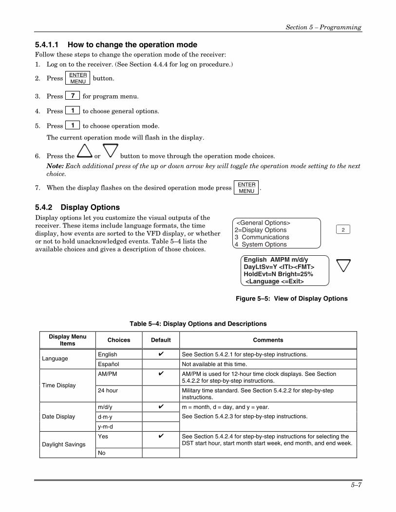
Section 5 – Programming
5–7
5.4.1.1 How to change the operation mode Follow these steps to change the operation mode of the receiver: 1. Log on to the receiver. (See Section 4.4.4 for log on procedure.)
2. Press ENTER MENU button.
3. Press 7 for program menu.
4. Press 1 to choose general options.
5. Press 1 to choose operation mode.
The current operation mode will flash in the display.
6. Press the or button to move through the operation mode choices.
Note: Each additional press of the up or down arrow key will toggle the operation mode setting to the next choice.
7. When the display flashes on the desired operation mode press ENTER MENU .
5.4.2 Display Options Display options let you customize the visual outputs of the receiver. These items include language formats, the time display, how events are sorted to the VFD display, or whether or not to hold unacknowledged events. Table 5–4 lists the available choices and gives a description of those choices.
<General Options>2=Display Options3 Communications4 System Options
English AMPM m/d/yDayLtSv=Y <ITI><FMT>HoldEvt=N Bright=25% <Language <=Exit>
2
Figure 5–5: View of Display Options
Table 5–4: Display Options and Descriptions
Display Menu Items
Choices Default Comments
English ✔ See Section 5.4.2.1 for step-by-step instructions. Language
Español Not available at this time.
AM/PM ✔ AM/PM is used for 12-hour time clock displays. See Section 5.4.2.2 for step-by-step instructions.
Time Display 24 hour Military time standard. See Section 5.4.2.2 for step-by-step
instructions.
m/d/y ✔
d·m·y
m = month, d = day, and y = year.
See Section 5.4.2.3 for step-by-step instructions. Date Display
y-m-d
Yes ✔ See Section 5.4.2.4 for step-by-step instructions for selecting the DST start hour, start month start week, end month, and end week. Daylight Savings
No

MX8000 Installation and Operation Guide
5–8
Table 5–4: Display Options and Descriptions (cont’d) Display Menu
Items Choices Default Comments
Attempts No See Section 5.4.2.5 for step-by-step instructions. CPU Time No CPU Type No Panel Rev No
ITI (Edit Options)
Arming Level No FSK1 English
BFSK Code If “English” is selected then the printer and VFD output for calls of these formats will be text descriptions. If “Code” is selected then the printer and VFD output for calls of these formats will be the Code and Zone numbers. See Section 5.4.2.6 for step-by-step instructions.
SIA English If “English” is selected, the printer and VFD output will be text. If “Code” is selected then the printer and VFD will display the SIA codes followed by zone or other information. See Section 5.4.2.6 for step-by- step instructions.
CID Code This option only affects the ADEMCO 8000 automation protocol output. If “English” is selected each event will be sent to the automation as two SIA events; the first with the two digit Group number and the second with the three digit ID number. If “Code” is selected, each event is sent as eleven digits; two digits Message type, one-digit Event Qualifier, three-digit Event Code, two-digit Group Number, and three-digit ID number. See Section 5.4.2.6 for step-by-step instructions.
PULSE 0 .. 9 If “0 .. 9” is selected hexadecimal digits B through F are forced to 0 as in the way the SK9000 receiver does it, or if “0 .. F” is selected digits are sent as is.
SK9000 Packed Each data packet to the automation contains a single (unpacked) or multiple (packed) events.
ACRON Zero Defines leading character in a 3-digit account number as a zero or space.
FMT (Edit Format Options)
HISPEED SIA Printer output will be in SIA format if “SIA” is selected or in a raw data high speed format if “Hispeed” is selected.
Yes VFD will display the last acknowledged event instead of the date/time display in the auto mode. In manual mode the display will show the oldest unacknowledged event. Hold Last Event
No ✔ Off
25% ✔
50%
75%
Bright
Max
Set the brightness of the Normal Operating Mode Display screen. All other screens will be displayed at Maximum. See Section 5.4.2.8 for step-by-step instructions.
5.4.2.1 How to Change Language Display 1. Enter program mode. (See Section 5.1.)
2. Press 1 for general options.
3. Press 2 for display options.
4. Press until the display flashes on the language format field.
5. Press the or button until the display flashes on the desired setting. Note: Only English format is available at this time.
6. Press ENTER
MENU .

Section 5 – Programming
5–9
5.4.2.2 How to Change Time Format Display 1. Enter program mode. (See Section 5.1.)
2. Press 1 for general options.
3. Press 2 for display options.
4. Press until the display flashes on the time format field.
5. Press the or button until the display flashes on the desired setting.
6. Press ENTER MENU .
5.4.2.3 How to Change Date Format Display 1. Enter program mode. (See Section 5.1.)
2. Press 1 for general options.
3. Press 2 for display options.
4. Press until the display flashes on the date format field.
5. Press the or button until the display flashes on the desired setting.
6. Press ENTER MENU .
5.4.2.4 How to Select and Set Daylight Savings 1. Enter program mode. (See Section 5.1.)
2. Press 1 for general options.
3. Press 2 for display options.
4. Press until the display flashes on the daylight savings time field.
5. Press ENTER MENU .
6. Press the or button until the display flashes on the desired setting for enabling (Y) or disabling (N) daylight savings time.
7. Press to advance to the hour field.
8. Press the or button until the display flashes on the desired hour for daylight savings time to take effect.
9. Press to advance to the start month field.

MX8000 Installation and Operation Guide
5–10
10. Press the or button until the display flashes on the desired month for daylight savings time to take effect.
11. Press to advance to the start week field.
12. Press the or button until the display flashes on the desired week for daylight savings time to take effect.
13. Press to advance to the end month field.
14. Press the or button until the display flashes on the desired month for daylight savings time to end.
15. Press to advance to the end week field.
16. Press the or button until the display flashes on the desired week for daylight savings time to end.
17. Press to return to the field for enabling or disabling daylight savings time.
18. Press .
5.4.2.5 How to Edit ITI Options If one of the following ITI options is turned on (set to Yes) then the VFD and printer outputs will include that information.
• Attempts • CPU Time • CPU Type • Panel Rev • Arming Level
To set these display options follow these steps:
1. Enter program mode. (See Section 5.1.)
2. Press 1 for general options.
3. Press 2 for display options.
4. Press until the display flashes on the <ITI> savings field.
5. Press ENTER MENU .
6. Press the or button until the equal sign is on the desired option.

Section 5 – Programming
5–11
7. Press ENTER MENU to change the setting of that option.
Note: Additional presses of the enter button will toggle the setting between Yes and No.
8. Repeat steps 6 and 7 for any other ITI display options you wish to edit.
5.4.2.6 How to Edit Format Options To set these display options follow these steps:
1. Enter program mode. (See Section 5.1.)
2. Press 1 for general options.
3. Press 2 for display options.
4. Press until the display flashes on the <FMT> savings field.
5. Press ENTER MENU .
6. Press the or button until the equal sign is on the desired option.
7. Press ENTER MENU to change the setting of that option from “English” to “Code”.
For Pulse Format “0 to 9” or “0 to F” can be selected. For SK9000 “Packed or Unpacked” can be selected.
Note: Additional presses of the enter button will toggle the setting between English and Code.
8. Repeat steps 6 and 7 for any other FMT options you wish to edit.
5.4.2.7 How to Set Hold Last Event Hold last event will cause the VFD to display the last acknowledged event instead of the date/time display in the auto mode. In manual mode the display will show the oldest unacknowledged event. To set the hold last event function, proceed as follows:
1. Enter program mode. (See Section 5.1.)
2. Press 1 for general options.
3. Press 2 for display options.
4. Press until the display flashes on the hold last event field.
5. Press the or button until the display flashes on the desired setting.
6. Press ENTER MENU .
5.4.2.8 How to Set VFD Brightness Note: This field affects the Normal Operating Display screen ONLY. All other displays will be shown at maximum.
1. Enter program mode. (See Section 5.1.)
2. Press 1 for general options.
3. Press 2 for display options.

MX8000 Installation and Operation Guide
5–12
4. Press until the display flashes on the bright field.
5. Press the or button until the display flashes on the desired setting.
6. Press ENTER MENU .
5.4.3 Communications In the communication option the installer can configure the communication ports, automation configuration, annunciator configurations, and the auxiliary relay configurations. Table 5–5 lists the available choices and gives a description of those choices.
<Communications>1=Port Functions2 Com Port1: Unused3 Com Port2: Unused
<Communications>4=Par Port: Unused5 Automation Cfg6 Annunciator Cfg
<Communications>7=Aux Relay Cfg< Exit Menu
¯
¯
Figure 5–6: Communications Options Menu
Table 5–5: Communications Options and Description
Communications Menu Choices Options Default Comments
Unused ✔
Automation Com1
Printer
Unused ✔
Rules for Port Functions: 1. Functions in Brackets [ ] will not appear unless
“Automation” is selected for Com1 function. 2. Functions in { } will not appear unless “Printer” is
selected in Com1 or Par. 3. A function may be selected only once in the 3 ports
(only one printer, only one Diag, and so on). 4. All ports may be configured “Unused”. 5. Only Com Port 1 can be set as the primary
automation port. Diagnostics Would output raw Hex-ASCII code. Printer English output to a printer. [Auto Bkp] Would act as a backup automation port if a fault
occurred with the primary automation port. [Auto Bkp Prn] Would act as a backup print output port if a fault
occurred with the automation port.
Com2
[Printer Bkp] Would act as a backup printer port if a fault occurred with the primary printer port.
Unused ✔ Diagnostics Would output raw Hex-ASCII
code. Printer English output to a printer.
Communications Port Functions
Par [Auto Bkp Prn] Would act as a backup print
output port if a fault occurred with the automation port.
Note: The receiver printer port is enabled at the factory. You will receive a trouble condition when a printer is not attached.

Section 5 – Programming
5–13
Table 5–5: Communications Options and Description (cont’d)
Communications Menu
Choices Options Default Comments
38400 ✔
19200
9600
7200
4800
2400
1200
600
300
Baud
110
7 D (# Data Bits)
8 ✔
1 ✔ S (# Stop Bits)
2
Even
Odd P (Parity)
No ✔
Yes ✔ PortMon (Port Monitor) No
When set to Yes (recommended) the computer ready line is monitored.
Hdwr ✔ Unidirectional communication
Sfwr F (Flow)
None No supervision
Com Port 1
Init Str (Initialization String)
Two 20-character ESC command sequences. See Section 5.4.3.4 for step-by -step instructions.
Com Port 2 Same as Com Port 1
Par Port (Parallel Port)
Edit Init Str (Initialization String)
Two 20-character ESC command sequences. See Section 5.4.3.4 for step-by -step instructions.
SK9000
ADEM 8000 ✔
ITI Gen
ITIComp
ADEM 685
FBII 220
Format
CAPS
See Section 5.4.3.5 for programming steps. See Section 8 for more information on automation formats.
Y = Enabled
Hex N = Disabled ✔
When Hex Mode is enabled, any call data that is determined to be bad data will be output in Hex format. Only visible if ADEM 8000 or SK9000 format is selected.
Y = Enabled See Section 5.4.3.5 for programming steps. Heartbeat
N = Disabled ✔
Automation Cfg
Time (of Heartbeat)
10-600 seconds 45 sec How often a supervisory signal (a heartbeat) is sent to the automation computer. See Section 5.4.3.5 for programming steps.

MX8000 Installation and Operation Guide
5–14
Table 5–5: Communications Options and Description (cont’d)
Communications Menu
Choices Options Default Comments
Ack Timeout 1-120 seconds 4 sec 15 seconds or less in UL applications. See Section 5.4.3.5 for programming steps.
<Cfg>
Term=013Head=010Ack=006
Nack=021Time
Req=005Time
Head=084Time
Term=020
Only visible if ADEMCO 685, FBII220 or CAPS ONLY format is selected. Note: Setting Ack and Nack to 0 disables Ack and Nack.
Y = Enabled
Sep N = Disabled ✔ Only visible if SK9000 format is selected. When enabled, a hex 05 is output for an account separator. When not selected, a hex 2E is output for an account separator.
Log Records ✔
Y = Enabled Enable External ID
N = Disabled ✔
Super Char
s
No Data Char
0
6.1 ✔
Automation Cfg (continued)
<ITI>
Generic Revision 6.2
Only visible if ITI Gen or ITIComp format is selected.
Yes ✔ Printer
No
Yes ✔ Bkp Printer
No
Yes ✔ Auto Comp
No
Yes ✔ Bkp Auto Comp
No
Yes = will annunciate on the receiver sounder if an event, trouble or fault condition occurs. No = no annunciation if an event, trouble or fault condition occurs. See Section 5.4.3.6 for programming steps.
Yes ✔ Battery
No
Yes ✔ Device
No
Device corresponds to loss of communication with slave or line card.
Yes ✔ Line Fault
No
Yes ✔ AC Power
No
Yes ✔ Buffer Full
No
Yes ✔ Listen In
No Listen in must be set to No for UL installations.
Yes ✔
Annunciator Cfg
Call Pending No
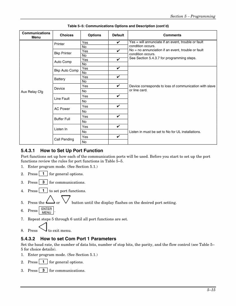
Section 5 – Programming
5–15
Table 5–5: Communications Options and Description (cont’d)
Communications Menu
Choices Options Default Comments
Yes ✔ Printer No
Yes ✔ Bkp Printer
No
Yes ✔ Auto Comp
No
Yes = will annunciate if an event, trouble or fault condition occurs. No = no annunciation if an event, trouble or fault condition occurs. See Section 5.4.3.7 for programming steps.
Yes ✔ Bkp Auto Comp No Yes ✔ Battery No Yes ✔
Device No
Device corresponds to loss of communication with slave or line card.
Yes ✔ Line Fault
No
Yes ✔ AC Power
No
Yes ✔ Buffer Full
No
Yes ✔ Listen In
No Listen in must be set to No for UL installations.
Yes ✔
Aux Relay Cfg
Call Pending No
5.4.3.1 How to Set Up Port Function Port functions set up how each of the communication ports will be used. Before you start to set up the port functions review the rules for port functions in Table 5–5. 1. Enter program mode. (See Section 5.1.)
2. Press 1 for general options.
3. Press 3 for communications.
4. Press 1 to set port functions.
5. Press the or button until the display flashes on the desired port setting.
6. Press ENTER MENU .
7. Repeat steps 5 through 6 until all port functions are set.
8. Press to exit menu.
5.4.3.2 How to set Com Port 1 Parameters Set the baud rate, the number of data bits, number of stop bits, the parity, and the flow control (see Table 5–5 for choice details). 1. Enter program mode. (See Section 5.1.)
2. Press 1 for general options.
3. Press 3 for communications.

MX8000 Installation and Operation Guide
5–16
4. Press 2 to set Com Port1 parameters.
5. Press the or button until the display flashes on the desired port setting.
6. Press ENTER MENU .
Note: See “How to Edit Init String (Com 1, Com 2, and Parallel Port)” in Section 5.4.3.4. 7. Repeat steps 5 through 6 until all parameters are set.
8. Press to exit menu.
5.4.3.3 How to Set Com Port 2 Parameters Set the baud rate, the number of data bits, number of stop bits, the parity, and the flow control (see Table 5–5 for choice details). 1. Enter program mode. (See Section 5.1.)
2. Press 1 for general options.
3. Press 3 for communications.
4. Press 3 to set Com Port 2 parameters.
5. Press the or button until the display flashes on the desired port setting.
6. Press ENTER MENU .
Note: See “How to Edit Init String (Com 1, Com 2, and Parallel Port)” in Section 5.4.3.4. 7. Repeat steps 5 through 6 until all parameters are set.
8. Press to exit menu.
5.4.3.4 How to Edit Init String (Com 1, Com 2, and Parallel Port) An initialization string can be used to customize the output to the device connected to a port on the receiver. For example, you can skip over perforations, set proportional spacing, or condense the print output to a printer. The display format for the init string is shown in Figure 5–7 and Table 5–6 lists the characters that can be entered into the string. Note: Refer to the user manual of the device connected to the receiver for special command sequences. Follow these steps to insert an initialization string:
<Edit Init String>_ _ _ _ _ _ _ _ _ _ _ _ _ _ _
Clear String=N
<Edit Init String>
_ _ _ _ _ _ _ _ _ _ _ _ _ _ _Clear String=N
First 20Digit String
Second 20Digit String
N = do not clear init stringY = Clear init string
Press to toggle Y or N
Ec= ESC or Escape
ENTERMENU
Figure 5–7: Initialization String Display

Section 5 – Programming
5–17
Table 5–6: Initialization String Characters
Character Description
0-9 Numeric characters, which can be entered from the touchpad or up/down arrows.
a-z and A-Z Alpha characters entered with the up/down arrows.
: _ - . , & * # ? E
C and space bar. Special Characters entered with the up/down arrows.
1. Press ENTER MENU at the flashing <Init Str> field.
2. Press the or button until the desired character flashes.
3. Press , the next character position will flash. 4. Repeat steps 2 and 3 until the desired sequence is complete.
5. Press ENTER MENU .
6. Repeat steps 2 through 5 for the second string.
To clear an init string:
1. At the Clear String=N field, press until the desired option flashes. See Figure 5–7.
2. Press ENTER MENU .
3. Press to exit menu.
5.4.3.5 How to Set Automation Communication Through this option the automation communication format and parameters can be set up. (See Table 5–5 for format choices.)
Note: After the automation format has been defined or changed, the output may not be correct until the receiver has been reset.
How to Set the Format
Follow these steps to set the automation communication format. 1. Enter program mode. (See Section 5.1.)
2. Press 1 for general options.
3. Press 3 for communications.
4. Press 5 to setup automation configuration.
5. Press the or button until the display flashes on the desired port setting.
6. Press ENTER MENU .
7. Press if you wish to exit menu or continue with heartbeat.
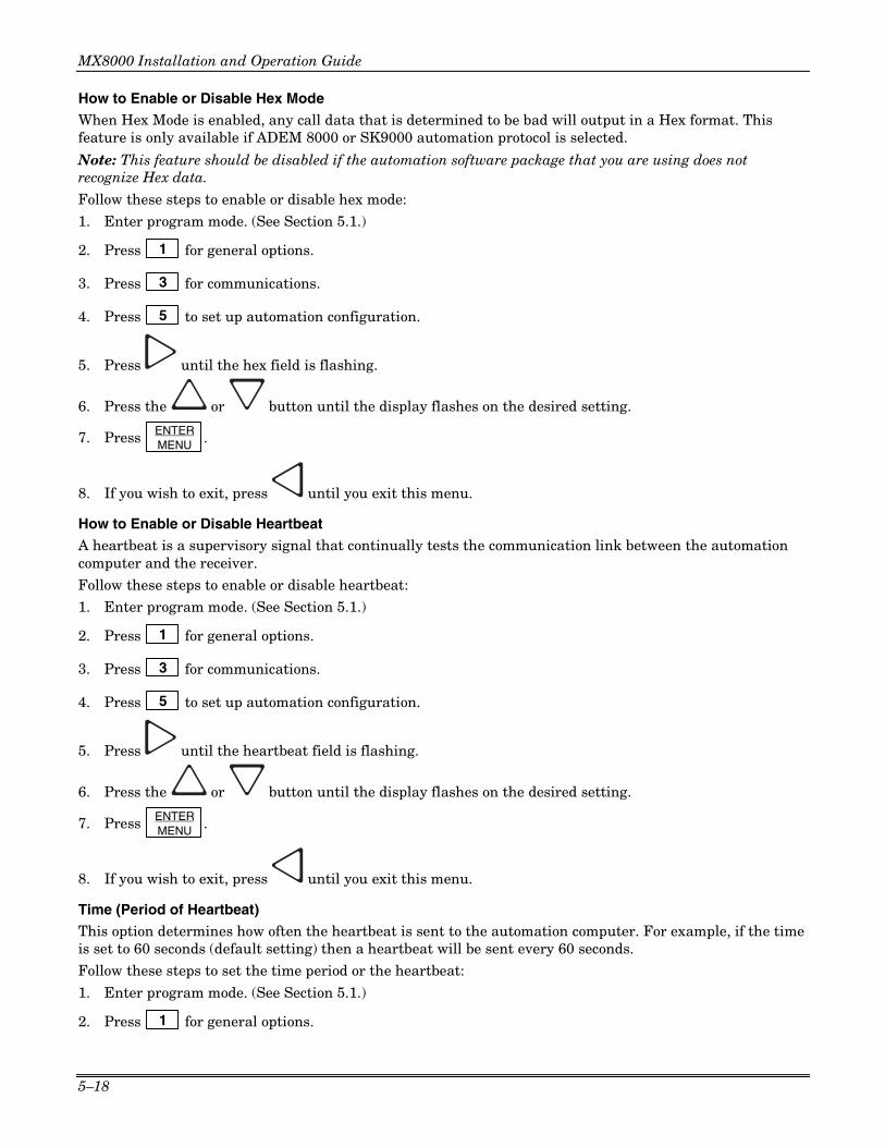
MX8000 Installation and Operation Guide
5–18
How to Enable or Disable Hex Mode
When Hex Mode is enabled, any call data that is determined to be bad will output in a Hex format. This feature is only available if ADEM 8000 or SK9000 automation protocol is selected.
Note: This feature should be disabled if the automation software package that you are using does not recognize Hex data.
Follow these steps to enable or disable hex mode: 1. Enter program mode. (See Section 5.1.)
2. Press 1 for general options.
3. Press 3 for communications.
4. Press 5 to set up automation configuration.
5. Press until the hex field is flashing.
6. Press the or button until the display flashes on the desired setting.
7. Press ENTER MENU .
8. If you wish to exit, press until you exit this menu.
How to Enable or Disable Heartbeat
A heartbeat is a supervisory signal that continually tests the communication link between the automation computer and the receiver. Follow these steps to enable or disable heartbeat: 1. Enter program mode. (See Section 5.1.)
2. Press 1 for general options.
3. Press 3 for communications.
4. Press 5 to set up automation configuration.
5. Press until the heartbeat field is flashing.
6. Press the or button until the display flashes on the desired setting.
7. Press ENTER MENU .
8. If you wish to exit, press until you exit this menu.
Time (Period of Heartbeat)
This option determines how often the heartbeat is sent to the automation computer. For example, if the time is set to 60 seconds (default setting) then a heartbeat will be sent every 60 seconds. Follow these steps to set the time period or the heartbeat:
1. Enter program mode. (See Section 5.1.)
2. Press 1 for general options.

Section 5 – Programming
5–19
3. Press 3 for communications.
4. Press 5 to set up automation configuration.
5. Press until the time field is flashing.
6. From the number keypad enter the desired number or press the or button until the display flashes on the desired setting.
7. Press ENTER MENU .
8. If you wish to exit, press until you exit this menu.
Ack Time (Acknowledge Time)
The acknowledge time is the duration that the receiver will wait for a response from the automation computer after a data packet has been sent. Data packets include all reports and heartbeats. Follow these steps to set the time period or the heartbeat: 1. Enter program mode. (See Section 5.1.)
2. Press 1 for general options.
3. Press 3 for communications.
4. Press 5 to set up automation configuration.
5. Press until the ack time field is flashing.
6. From the number keypad enter the desired number or press the or button until the display flashes on the desired setting.
7. Press ENTER MENU .
8. If you wish to exit, press until you exit this menu.
ITI Options (Only Visible if ITI Gen or ITIComp Formats are Chosen)
These are options particular to the ITI automation format and can only be edited if one of these formats is used to communicate with the automation computer. See Sections 8.8 and 8.10.
Follow these steps to set the ITI options: 1. Enter program mode. (See Section 5.1.)
2. Press 1 for general options.
3. Press 3 for communications.
4. Press 5 to set up automation configuration.
5. Press until the ack <ITI> field is flashing.
6. Press ENTER MENU .

MX8000 Installation and Operation Guide
5–20
Table 5–7: ITI Automation Format Options Option Choices Default Meaning Comments
Log Recs Y (Yes) N Log records identify the time and date of an incoming report.
N (No) XID Y (Yes) N Extended panel Identification code. See 8.9.2.2. N (No) SupCh s Supervisory Character is sent from the automation
computer. The receiver will respond with an OKAY or supervisory record. See Sections 8.9.5 and 8.10.5.
No Data 0 Identifies the no data character in the log record.
Note: ITI automation formats are covered in greater detail in Sections 8.8 and 8.10.
Log Recs (For ITI Formats):
1. At the flashing Log Recs field press the or button until the display flashes on the desired setting.
2. Press ENTER MENU .
3. If you wish to exit, press until you exit this menu.
XID (Extended ID for ITI Panels):
1. At the flashing XID field press the or button until the display flashes on the desired setting.
2. Press ENTER MENU .
3. If you wish to exit, press until you exit this menu.
SupCh (Supervisory Character):
1. At the flashing SupCh [s] field press the or button until the display flashes on the desired setting.
2. Press ENTER MENU .
3. If you wish to exit, press until you exit this menu.
NoData (No Data Character for Log Record): 1. At the flashing NoData[0] field enter a digit from 0-9 from the touchpad or press the
or button until the display flashes on the desired setting.
2. Press ENTER MENU .
3. If you wish to exit, press until you exit this menu.
5.4.3.6 How to Configure the On-board Annunciator Outputs Program what will give a trouble annunciation or what will not annunciate from the on-board annunciator. 1. Enter program mode. (See Section 5.1.)
2. Press 1 for general options.
3. Press 3 for communications.

Section 5 – Programming
5–21
4. Press 6 to set annunciator configuration.
A list of the annunciator output options appears.
5. Press the or button to move through the annunciator output options.
6. When the equal sign highlights the option you wish to change, press ENTER MENU .
Note: Additional presses of the enter button toggle the setting between “yes” or “no”. See Table 5–8. 7. Repeat steps 5 through 6 for all annunciator options you wish to change. See Table 5–8 for list of
additional options.
5.4.3.7 How to Configure the Auxiliary Relay Outputs Program what will give a trouble output to the auxiliary relay contact. (To program the normal state of the auxiliary relay, see Section 5.4.4.)
Note: Pressing ACK will silence an alarm, (essentially acknowledging the event), but the only way to reset the auxiliary relay contacts is to actually restore the trouble. As long as there are any troubles in the system, the contacts will be set. 1. Enter program mode. (See Section 5.1.)
2. Press 1 for general options.
3. Press 3 for communications.
4. Press 7 to set relay configuration.
A list of the relay output options appears.
5. Press the or button to move through the relay output options.
6. When the equal sign highlights the option you wish to change, press ENTER MENU .
Note: Additional presses of the enter button toggle the setting between “yes” or “no”. See Table 5–8. 7. Repeat steps 5 through 6 for all relay options you wish to change. See Table 5–8 for list of additional
options.
Table 5–8: On-board Annunciator and Auxiliary Relay Options Option Choices Comments
Printer Y (Yes)/N (No)
Bkp Printer Y (Yes)/N (No)
Auto Comp Y (Yes)/N (No)
Bkp Auto Comp Y (Yes)/N (No)
Y = Annunciator will beep and relay energize if there is an error condition.
N = No on-board annunciation or relay energizing if an error condition exist.
Battery Y (Yes)/N (No)
Device Y (Yes)/N (No)
Line Fault Y (Yes)/N (No)
AC Power Y (Yes)/N (No)
Buffer Full Y (Yes)/N (No)
Listen In Y (Yes)/N (No)
Call Pending Y (Yes)/N (No)

MX8000 Installation and Operation Guide
5–22
5.4.4 System Options In system options you can configure the backup battery configuration, the receiver ID number, and the normal state of the auxiliary relay.
<General Options>4=System Options5 Msg Queue Opt.
No Batt Bkp SingleRcvr ID=01 Strip BadAuxRly=Off Clk=60Hz <Batt Bkp <=Exit>
4
6 Slave List ¯
Figure 5–8: System Options Display
5.4.4.1 How to Change Backup Battery Setting Through system options the backup battery can be configured for the type of backup battery your installation site requires. 1. Enter program mode. (See Section 5.1.)
2. Press 1 for general options.
3. Press 4 for system options.
4. Press the or button until the display flashes on the desired setting.
5. Press ENTER MENU .
To Exit:
Press until you return to the main menu.
Table 5–9: System Options
System Options Menu
Choices Default Comments
No Battery Bkp ✔ No charging current applied to battery circuit. Receiver will not test battery output or give trouble annunciations.
Battery Bkp Charging current applied to battery circuit. Battery Backup Cfg DC Bkp No charging current applied to battery circuit. Typically
used for systems that use a UPS (uninterrupted power supply) for backup battery power.
Single ✔ Receiver is operating independently.
Slave Receiver is a slave to a master receiver. Receiver Mode
Master Receiver is a master.
Receiver ID 01-99 01
Strip Bad ✔ If this is selected an indicator will be sent to the automation computer that indicates a bad data block was received. Bad Data Blocks
Send Bad Same as Strip Bad except the bad data block is sent with the indicator.
Off (De-energized) ✔ Aux Relay Normal State On (Energized)
See Section 5.4.4.5 for auxiliary relay output options.
60Hz ✔ Synchronize clock to 60Hz Line input.
50Hz Synchronize clock to 50Hz Line input.
Clock Source
Int (Internal) Synchronize clock to internal crystal.

Section 5 – Programming
5–23
5.4.4.2 How to Set the Receiver as a Single, Slave, or Master In large central stations, it may be desired to set up receivers in a master/slave relationship for reporting to a printer. To set the receiver to act as a single receiver, master receiver, or slave receiver, proceed as follows: 1. Enter program mode. (See Section 5.1.)
2. Press 1 for general options.
3. Press 4 for system options.
4. Press . The display will flash on the receiver mode: Single
5. Press the or button until the display flashes on the desired setting.
6. Press ENTER MENU .
To Exit:
Press until you return to the main menu.
5.4.4.3 How to Set the Receiver ID Number In large central stations where calls may be coming in on several receivers at once, the automation software will need to identify which receiver it received a call from. This will help in troubleshooting if a problem occurred with the automation system or receiver. 1. Enter program mode. (See Section 5.1.)
2. Press 1 for general options.
3. Press 4 for system options.
4. Press . The display will flash on the receiver ID number: Rcvr ID=01
5. Enter the desired receiver ID number (a number from 01 to 99). Note: If you are outputting to an automation computer using 685, CAPS, or CP-220 automation protocol, see Table 5–10 for valid entries for ID numbers 1–9 and A–Z.
6. Press ENTER MENU .
To Exit:
Press until you return to the main menu.
Table 5–10: 685, CAPS, and CP-220 1–9/A–Z Entries Keypad Entry
Number/Letter
Keypad Entry
Number/Letter
Keypad Entry
Number/Letter
Keypad Entry
Number/Letter
01 1 65 A 74 J 83 S 02 2 66 B 75 K 84 T 03 3 67 C 76 L 85 U 04 4 68 D 77 M 86 V 05 5 69 E 78 N 87 W 06 6 70 F 79 O 88 X 07 7 71 G 80 P 89 Y 08 8 72 H 81 Q 90 Z 09 9 73 I 82 R

MX8000 Installation and Operation Guide
5–24
5.4.4.4 How to Configure Output for Bad Data Blocks This feature selects how bad data blocks will be sent from the receiver to the automation computer. If Strip Bad is selected then an indicator will be sent to the automation computer when a bad data block is received, but the actual bad data block will not be sent. If Send Bad is selected an indicator will be sent to the automation computer along with the bad data block. 1. Enter program mode. (See Section 5.1.)
2. Press 1 for general options.
3. Press 4 for system options.
4. Press . The display will flash on the Bad Data Blocks: Strip_Bad
5. Press the or button until the display flashes on the desired setting.
6. Press ENTER MENU .
To Exit:
Press until you return to the main menu.
5.4.4.5 How to Set the Normal State of the Auxiliary Relay Contact The auxiliary relay contact is a Form C relay. This feature allows you to set the state of the auxiliary relay normally open contact when power is applied to the receiver. 1. Enter program mode. (See Section 5.1.)
2. Press 1 for general options.
3. Press 4 for system options.
4. Press . The display will flash on the auxiliary relay setting: Aux Relay=Off
5. Press the or button until the display flashes on the desired setting.
6. Press ENTER MENU .
To Exit:
Press until you return to the main menu.
5.4.4.6 How to Set Clock Synchronization Source This feature allows you to set the synchronization source for the receiver’s clock. 1. Enter program mode. (See Section 5.1.)
2. Press 1 for general options.
3. Press 4 for system options.
4. Press . The display will flash on the clock: Clk=60Hz

Section 5 – Programming
5–25
5. Press the or button until the display flashes on the desired setting.
6. Press ENTER MENU .
To Exit:
Press until you return to the main menu.
5.4.5 Message Queue Options Set the percentage of how full the message queue must be before a “Message Queue Warning' and “Message Queue Warning Restore” occur. See Section 7 for trouble messages. Note: The “Warning On” can be set from 10% to 99%; the “Warning Off” can be set from 1% to 90%. A mini-mum separation of 5% will be set between the On % and the Off %. For example, if the “Warning On” is set to 82% the “Warning Off” maximum setting can be 77%.
<General Options>5=Msg Queue Opt.6 Slave List
<Msg Queue Menu>Wrn Lvl On:75 Off:50Event Release: 060<%Wrng On <=Exit >
5
7 Virtual Receiver ¯
Figure 5–9: Message Queue Display
5.4.5.1 Set the Message Queue Warning On level Set the percentage of how full the message queue can get before the receiver indicates a “Message Queue Warning” condition. 1. Enter program mode. (See Section 5.1.)
2. Press 1 for general options.
3. Press 5 for message queue options.
4. Enter the level (in %) you wish the receiver message queue to get before it will indicate a message queue warning.
5. Press ENTER MENU .
To Exit:
Press until you return to the main menu.
5.4.5.2 Set the Message Queue Warning Off Level Set the percentage level where the receiver will indicate a restore condition for a “Message Queue Warning”. 1. Enter program mode. (See Section 5.1.)
2. Press 1 for general options.
3. Press 5 for message queue options.
4. Press until the display flashes on the Off field. 5. Enter the level (in %) you wish the receiver message queue to get before it will indicate a message queue
warning restore.
6. Press ENTER MENU .
To Exit:
Press until you return to the main menu.

MX8000 Installation and Operation Guide
5–26
5.4.5.3 Set the Event Release Time Used to define the maximum amount of time (in seconds) that the receiver will hold an event in memory prior to sending it to automation, VFD, and printer. The time begins at the beginning of the call or on an acknowledgement. Notes: • If the Event Release setting is "greater" than the Call Hang-Up setting (see page5–49), the receiver will not
disconnect the line (panel) until the Event Release time has expired. • The actual amount of time before the receiver disconnects a line may at times be greater than the actual
programmed value for Call Hang-Up Time. An event in progress (Event Release) has to complete before the call hang-up takes affect.
1. Enter program mode. (See Section 5.1.)
2. Press 1 for general options.
3. Press 5 for message queue options.
4. Press until the display flashes on the Event Release field. 5. Enter the event release time (001 or 020 to 120) in seconds.
6. Press ENTER MENU .
To Exit:
Press until you return to the main menu.
5.4.6 Slave List Through the slave list menu, you can add a slave receiver, view a slave, or delete a slave. Notes: • For this menu to be available, the receiver being programmed
must be a master receiver as detailed in Section 5.4.4.2. • The slave ID number must be different than the master
receiver ID number and also must be different than any other slave receiver ID number that is reporting to the master receiver.
<General Options>
<Slave ID's>1=Add SLave2 View Slave3 Delete Slave
66=Slave List7 Virtual Receiver
¯
< Exit Menu
Figure 5–10: Slave List Display
5.4.6.1 Add Slave To add a slave to a master receiver: 1. Enter program mode. (See Section 5.1.)
2. Press 1 for general options.
3. Press 6 for slave list options.
4. Press 1 to select add slave.
5. The receiver will display the message: Enter Slave #: 00 6. Enter a 2-digit slave ID number.
7. Press ENTER MENU .
8. To define a second slave receiver, enter second 2-digit slave ID number.
9. Press ENTER MENU .
To Exit:
Press until you return to the main menu.

Section 5 – Programming
5–27
5.4.6.2 View Slave To view a slave to a master receiver: 1. Enter program mode. (See Section 5.1.)
2. Press 1 for general options.
3. Press 6 for slave list options.
4. Press 2 to select view slave.
5. The receiver will display a listing of slave receivers assigned.
To Exit:
Press until you return to the main menu.
5.4.6.3 Delete Slave To delete a slave from a master receiver: 1. Enter program mode. (See Section 5.1.)
2. Press 1 for general options.
3. Press 6 for slave list options.
4. Press 3 to select delete slave.
5. The receiver will display a listing of slave receivers assigned.
6. Select a receiver for deletion using the or keys.
7. Press ENTER MENU .
8. The receiver will display:
Snn 8000 Slave Delete Record? No
9. Toggle the yes/no display using the or keys.
10. Press ENTER MENU with yes displayed to delete the receiver.
11. Repeat steps 4 through 10 to delete another receiver.
To Exit:
Press until you return to the main menu.
5.4.7 Virtual Receiver/Line Numbers The use of virtual receiver numbers allows multiple receiver numbers to be assigned in the same MX8000 or multiple MX8000s if operating in the master/slave configuration. Each virtual receiver number can have from 1 to 99 line(s) assigned to it.
The virtual receiver and line number(s) are used when displaying, printing, or sending data to the automation system. If desired, the same virtual line # can be assigned to more than one line in the same MX8000.
<General Options>
L01=Rec#00 Lin#001L02=Rec#00 Lin#001L03=Rec#00 Lin#001<Virtual Receiver>
77=Virtual Receiver< Exit Menu
¯ Figure 5–11: Virtual Receiver/Line Numbers
Display

MX8000 Installation and Operation Guide
5–28
To assign virtual receiver and virtual line numbers: Notes: • If virtual receiver/line numbers are being used, DO NOT assign a hunt group number to a line. If a hunt
group number is assigned, it takes precedence and the virtual number will not be used. • Virtual receiver/line numbers will not be used when reporting an expander trouble. For an expander
troubles, the actual receiver/line number will be used.
1. Enter program mode. (See Section 5.1.)
2. Press 1 for general options.
3. Press 7 for virtual receiver/line numbers.
The display will flash on the virtual receiver number of the first line in the receiver: L01=Rec# 00
Note: The display will list all physical lines in the receiver.
4. Enter the desired virtual receiver number (a number from 00 to 99).
Notes: • If the virtual receiver number is programmed as zero for a given line then the system receiver number
will be used for the line’s receiver number and the line number will be the lines physical number. • If you are outputting to an automation computer using 685, CAPS, or CP-220 automation protocol, see
Table 5–10 on page 5–23 for valid entries for ID numbers 1–9 and A–Z.
5. Press to advance to the virtual line number field. 6. Enter the desired virtual line number (a number from 001 to 099).
Note: For proper reporting to an automation computer, use 008 or less when using 685 or CAPS automation protocol or 015 or less if using CP-220 automation protocol.
7. Press ENTER MENU to accept the entry and advance to the next line or press if the line contains an error
that you need to correct.
8. Repeat steps 4 through 7 for each virtual receiver/line to be defined.
To Exit:
Press until you return to the main menu.
5.5 Line Device Menu Through the Line Device menu you can add a new Line Card and edit, clear, or view existing Line Devices. Table 5–11 lists the menu options available under Line Device menu.
<Program Menu>2=Line Device Menu3 User List< Exit
2
<Select Device Type>1=MX8000-LC32 MX8000-LRR3 MX8000-LC1
<Device Program>1=Add Device2 Edit Line3 Copy Device(s) ¯
<Device Program>4=Clear Device5 View Device< Exit Menu
¯
Figure 5–12: Choosing Line Device Menu
and Line Device Program Menu Items

Section 5 – Programming
5–29
Table 5–11: Line Device Menu Options
Select Device Type
Line Device Menu Choice Choice Choice Choice Default Comments
Use Defaults
Add Device
Enter Device # Copy
Existing
1 2 3 4 5
Sequence Number
6
See the corresponding numbers below.
The order in which the Line will output different handshakes. For more information see page 5–39
1400_2300–2 1. 1400Hz 2. 2300Hz 3. 2225Hz 4. Modem II 5. Modem IIE 6. Westec 1400_2300Hz
Format Group
Unused
Number in default column indicates the default handshake sequence number. For more information see page 5–40
1. 100 2. 1000 3. 1000 4. 0900 5. 1000
Handshake Duration
0-9999 In 1ms periods
6. 1520
For more information see page 5–40
1. 1250 2. 3200 3. 3200 4. 3200 5. 3200
Handshake Wait
0-9999 In 1ms periods
6. 3200
For more information see page 5–40
1. 0800 2. 1200 3. 1200 4. 0750 5. 0600
Handshake Sequence
Handshake Acknowl-edge Duration
0-9999 In 1ms periods
6. 0600
For more information see page 5–40
4/1 3/2 5-Digit
Format 3/1CS (with checksum)
4/1
If a pulse comes in a 5-digit format then the data will then be treated as the selected format.
4/2
3/2CS (with checksum)
MX8000–LC3 3 Line
Edit Line Line #
Pulse Format
6-Digit Format
4/1CS (with checksum)
4/2
If a pulse comes in a 6-digit format then the data will then be treated as the selected format.

MX8000 Installation and Operation Guide
5–30
Table 5–11: Line Device Menu Options (cont’d)
Select Device Type
Line Device Menu Choice Choice Choice Choice Default Comments
Inter-digit Tm (ms)
0 or 1 ms to 2 Sec.
0
This feature selects the time period between data blocks. See page 5–41 for more information.
Ack on Even Round
Yes or No No
Select this option if the 1400 or 2300 Hz format requires an Ack tone on even rounds.
Pulse Format (cont’d)
Partially Extended
Yes or No Yes
Select this option if you have multiple extended data blocks for 3/ 1 or 4/1 formats.
Y (Yes)
Direct
No (No) ✔
Y = dedicated or direct connect phone line. N = used for standard phone lines. See page 5–42 for more information.
Number of Rings
0-255 002 If caller ID is turned on (see Section 5.5.2.5), rings should be set to 2. It is recommended that the number of rings is not set to a value greater than 5.
Country Country USA Select country from listing.
Threshold 1-15 in 2.75 VDC steps
08 (22.0VDC) See page 5–43 for more information.
Line Options
Sample Time
00-99 seconds
08 (8 seconds)
See page 5–43 for more information.
Not Used ✔
Common See page 5–44 for more information. Must not be used in UL installations. Listen Mode
PBX PBX String edit
See page 5–44 for more information.
Timeout 0-255 0 See page 5–45 for more information.
Add Account None Edit Account
Listen In
Listen In account edit
Clear Account
See page 5–45 for more information.
Y (Yes)
MX8000–LC3 3 Line (cont’d)
Edit Line (cont’d)
Line # (cont’d)
Misc. Line Options
Echo Suppress
N (No) ✔
Outputs a 2 second 2025Hz tone to disable echo suppression equipment that may interfere with modem formats.
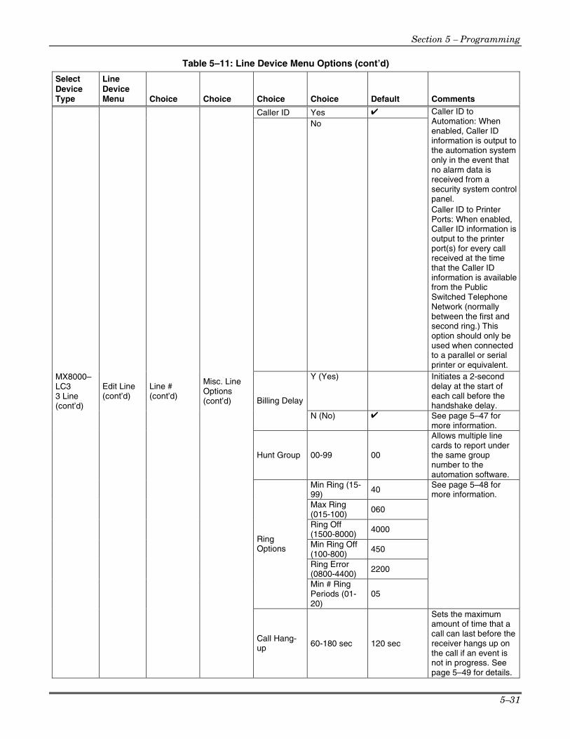
Section 5 – Programming
5–31
Table 5–11: Line Device Menu Options (cont’d)
Select Device Type
Line Device Menu Choice Choice Choice Choice Default Comments
Caller ID Yes ✔
No
Caller ID to Automation: When enabled, Caller ID information is output to the automation system only in the event that no alarm data is received from a security system control panel. Caller ID to Printer Ports: When enabled, Caller ID information is output to the printer port(s) for every call received at the time that the Caller ID information is available from the Public Switched Telephone Network (normally between the first and second ring.) This option should only be used when connected to a parallel or serial printer or equivalent.
Y (Yes) Initiates a 2-second delay at the start of each call before the handshake delay.
Billing Delay
N (No) ✔ See page 5–47 for more information.
Hunt Group 00-99 00
Allows multiple line cards to report under the same group number to the automation software.
Min Ring (15-99) 40
Max Ring (015-100)
060
Ring Off (1500-8000) 4000
Min Ring Off (100-800)
450
Ring Error (0800-4400) 2200
Ring Options
Min # Ring Periods (01-20)
05
See page 5–48 for more information.
MX8000–LC3 3 Line (cont’d)
Edit Line (cont’d)
Line # (cont’d)
Misc. Line Options (cont’d)
Call Hang-up 60-180 sec 120 sec
Sets the maximum amount of time that a call can last before the receiver hangs up on the call if an event is not in progress. See page 5–49 for details.

MX8000 Installation and Operation Guide
5–32
Table 5–11: Line Device Menu Options (cont’d)
Select Device Type
Line Device Menu Choice Choice Choice Choice Default Comments
4/2
In High Speed, messages with event codes of B, C, E, and F are translated to ADEMCO High Speed messages.
BFSK Auto
High Speed ✔ 3/1 ✔
3/1 Restore High Speed
Standard method: 123 2, 123 9 Converted to High Speed: 0123 5355 5555 7
Normal
4/2 Out High Speed ✔
In High Speed mode, messages with event codes of B and C are translated to High Speed Opening and Closing messages, respectively.
S/Fast ✔ FBI
LAR300 Extended ✔
Pulse Extended Not Extended
A sequence of 1234 B , BBBB 7 is combined into a 4-2 message of 1234 B7. (Applies to B,C,E,F). This mes-sage would either be put out to Automation as 4-2 or High Speed. When the option is selected, the receiver does not combine the expanded messages. They are output in the same form as received.
High Speed ✔
Ademco Auto Opt
Extended Output 4/2
If low speed expanded messages are received and combined (See Pulse Extended above), the messages are output to Automation as 4-2 format messages. For example, a sequence of 1234 B , BBBB 7 is combined and output as a 4-2 message of 1234 B7.
Transmit Gain
–3 through –6, –8, –10, –11, –12, or –14dB
–8db
MX8000–LC3 3 Line (cont’d)
Edit Line (cont’d)
Line # (cont’d)
Line Gain Opt
Receive Gain
0 through 12dB in 3dB steps
6db
Controls the transmit and receive gain for the line.

Section 5 – Programming
5–33
Table 5–11: Line Device Menu Options (cont’d)
Select Device Type
Line Device Menu Choice Choice Choice Choice Default Comments
CID Monitor Norm, Pream, DTMF, or Marks
Norm
CID Gain –6, –2, 0, 2, 3.5, 4.8, 6, or 7dB
2dB
On Hook Gain
2, 3.5B, 4.8, 6, or 7dB 7dB
Edit Line (cont’d)
Line # (cont’d)
Line Gain Opt (cont’d)
Ringer Impedance Hi or Sy Hi
Used to set Caller ID detection methods, gain, and impedance. See Section 5.5.2.7 for more information. These options are only used if Caller ID is enabled as described in Section 5.5.2.5.
Use Default Device #
Choose Device(s) # that you wish to be programmed to factory defaults.
Copy Device(s)
Copy Existing
Device # of Source & Target Device
Copy the program-ming of one Device (source) and paste it into one or several (target) Devices.
Clear Device
Choose Device #
Deletes a Device from the receiver.
MX8000–LC3 3 Line (cont’d)
View Device
Choose Device #
Views what Devices are installed.
Use Defaults
Add Device Device #
Copy Existing
Central Station #
000-255 017
Odd/Even Network
Odd/Even Even
VPN Yes/No No
A/B Network A/B A
Edit Line
Monitor Station Flag
Yes/No No
Use Default Device #
Choose Device(s) # that you wish to be programmed to factory defaults.
Copy Device(s)
Copy Existing
Device # of Source & Target Device
Copy the programming of one Device (source) and paste it into one or several (target) Devices.
Clear Device(s)
Choose Device #
Deletes a Device from the receiver.
MX8000–LRR
View Device(s)
Choose Device #
Views what Devices are installed.

MX8000 Installation and Operation Guide
5–34
Table 5–11: Line Device Menu Options (cont’d)
Select Device Type
Line Device Menu Choice Choice Choice Choice Default Comments
Use Defaults
Add Device
Device # Copy Existing
1
2
3
4
5
Sequence Number
6
See the corresponding numbers below.
The order in which the device will output different handshakes.
For more information see page 5–57.
1400_2300–2 1
1400Hz 2
2300Hz 3
2225Hz 4
Modem II 5
Modem IIE 6
Westec
1400_2300Hz
Format Group
Not Used
Number in default column indicates the default handshake sequence number.
For more information see page 5–57
1. 002 (100ms)
2. 002 (100ms)
3. 002 (100ms)
4. 010 (500ms)
5. 002 (100ms)
Handshake Delay
0-255 In 50ms periods
6. 002 (100ms)
For more information see page 5–57
1. 010 (100ms)
2. 100 (1 sec)
3. 100 (1 sec)
4. 090 (900ms)
5. 100 (1 sec)
Handshake Duration
0-255 In 10ms periods
6. 152 (1.52 sec)
For more information see page 5–58
1. 025 (1.25 sec)
2. 064 (3.2 sec)
3. 064 (3.2 sec)
4. 064 (3.2 sec)
5. 064 (3.2 sec)
Handshake Wait
0-255 In 50ms periods
6. 064 (3.2 sec)
For more information see page 5–40
1. 055 (800ms)
2. 120 (1.2 sec)
3. 120 (1.2 sec)
4. 075 (750ms)
5. 060 (600ms)
MX8000–LC1 1 Line
Edit Line
Line #
Handshake Sequence
Handshake Acknowl-edge Duration
0-255 In 10ms periods
6. 060 (600ms)
For more information see page 5–58
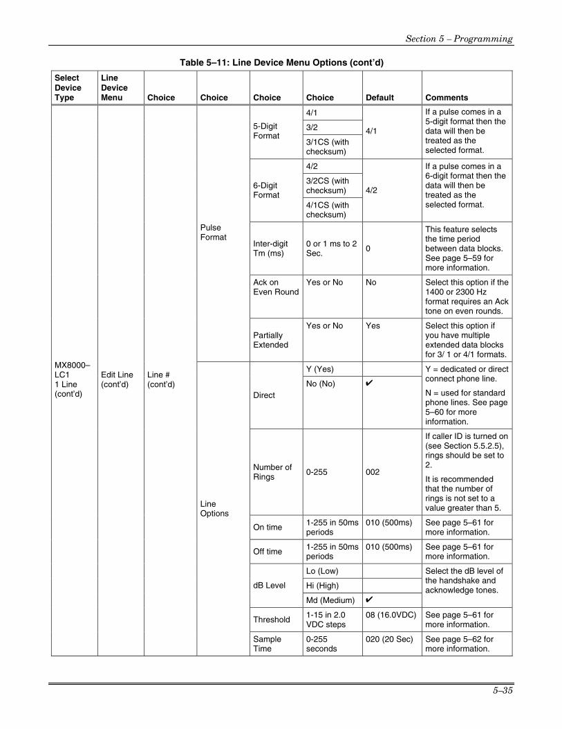
Section 5 – Programming
5–35
Table 5–11: Line Device Menu Options (cont’d)
Select Device Type
Line Device Menu Choice Choice Choice Choice Default Comments
4/1
3/2 5-Digit Format
3/1CS (with checksum)
4/1
If a pulse comes in a 5-digit format then the data will then be treated as the selected format.
4/2
3/2CS (with checksum)
6-Digit Format
4/1CS (with checksum)
4/2
If a pulse comes in a 6-digit format then the data will then be treated as the selected format.
Inter-digit Tm (ms)
0 or 1 ms to 2 Sec. 0
This feature selects the time period between data blocks. See page 5–59 for more information.
Ack on Even Round
Yes or No No Select this option if the 1400 or 2300 Hz format requires an Ack tone on even rounds.
Pulse Format
Partially Extended
Yes or No Yes Select this option if you have multiple extended data blocks for 3/ 1 or 4/1 formats.
Y (Yes)
Direct No (No) ✔
Y = dedicated or direct connect phone line.
N = used for standard phone lines. See page 5–60 for more information.
Number of Rings
0-255 002
If caller ID is turned on (see Section 5.5.2.5), rings should be set to 2.
It is recommended that the number of rings is not set to a value greater than 5.
On time 1-255 in 50ms periods
010 (500ms) See page 5–61 for more information.
Off time 1-255 in 50ms periods
010 (500ms) See page 5–61 for more information.
Lo (Low)
Hi (High) dB Level
Md (Medium) ✔
Select the dB level of the handshake and acknowledge tones.
Threshold 1-15 in 2.0 VDC steps
08 (16.0VDC) See page 5–61 for more information.
MX8000–LC1 1 Line (cont’d)
Edit Line (cont’d)
Line # (cont’d)
Line Options
Sample Time
0-255 seconds
020 (20 Sec) See page 5–62 for more information.

MX8000 Installation and Operation Guide
5–36
Table 5–11: Line Device Menu Options (cont’d)
Select Device Type
Line Device Menu Choice Choice Choice Choice Default Comments
Not Used ✔
Common
See page 5–62 for more information. Must not be used in UL installations. Listen Mode
PBX PBX String edit
See page 5–62 for more information.
Timeout 0-255 0 See page 5–63 for more information.
Add Account None Edit Account
Listen In
Listen In account edit
Clear Account
See page 5–63 for more information.
Y (Yes)
Echo Suppress
N (No) ✔
Outputs a 2 second 2025Hz tone to disable echo suppression equipment that may interfere with modem formats.
Yes ✔
Caller ID No
Caller ID to Automation: When enabled, Caller ID information is output to the automation system only in the event that no alarm data is received from a security system control panel. Caller ID to Printer Ports: When enabled, Caller ID information is output to the printer port(s) for every call received at the time that the Caller ID information is available from the Public Switched Telephone Network (normally between the first and second ring.) This option should only be used when connected to a parallel or serial printer or equivalent.
Y (Yes) Initiates a 2-second delay at the start of each call before the handshake delay. Billing Delay
N (No) ✔ See page 5–65 for more information.
MX8000–LC1 1 Line (cont’d)
Edit Line (cont’d)
Line # (cont’d)
Misc. Line Options
Hunt Group 00-99 00
Allows multiple line cards to report under the same group number to the automation software.

Section 5 – Programming
5–37
Table 5–11: Line Device Menu Options (cont’d)
Select Device Type
Line Device Menu Choice Choice Choice Choice Default Comments
Misc. Line Options (cont’d)
Call Hang-up 60-180 sec 120 sec
Sets the maximum amount of time that a call can last before the receiver hangs up on the call if an event is not in progress. See page 5–66 for details.
4/2
BFSK Auto High Speed ✔
In High Speed, messages with event codes of B, C, E, and F are translated to ADEMCO High Speed messages.
3/1 ✔
3/1 Restore High Speed
Standard method: 123 2, 123 9 Converted to High Speed: 0123 5355 5555 7
Normal
4/2 Out High Speed ✔
In High Speed mode, messages with event codes of B and C are translated to High Speed Opening and Closing messages, respectively.
S/Fast ✔ FBI
LAR300 Extended ✔
Pulse Extended Not Extended
A sequence of 1234 B , BBBB 7 is combined into a 4-2 message of 1234 B7. (Applies to B,C,E,F). This mes-sage would either be put out to Automation as 4-2 or High Speed. When the option is selected, the receiver does not combine the expanded messages. They are output in the same form as received.
High Speed ✔
MX8000–LC1 1 Line (cont’d)
Edit Line (cont’d)
Line # (cont’d)
Ademco Auto Opt
Extended Output 4/2
If low speed expanded messages are received and combined (See Pulse Extended above), the messages are output to Automation as 4-2 format messages. For example, a sequence of 1234 B , BBBB 7 is combined and output as a 4-2 message of 1234 B7.

MX8000 Installation and Operation Guide
5–38
Table 5–11: Line Device Menu Options (cont’d)
Select Device Type
Line Device Menu Choice Choice Choice Choice Default Comments
Use Defaults
Choose Device(s) #
Choose Device(s) # that you wish to be programmed to factory defaults.
Copy Device(s) Copy
Existing Choose Device # of Source & Target Device
Copy the program-ming of one Device (source) and paste it into one or several (target) Devices.
Clear Device
Choose Device #
Deletes a Device from the receiver.
MX8000–LC1 1 Line (cont’d)
View Device
Choose Device #
Views what Devices are installed.
5.5.1 Add Line Device To program in a new line device, follow these steps: 1. Install the new line device. (See Section 3.7.) 2. Log on to the receiver. (See Section 4.4.4 for log on procedure.)
3. Press ENTER MENU button.
4. Press 7 for program menu.
The display will briefly display Initializing Please wait . . .
5. Press 2 to choose Line Device menu.
6. Press 1 , 2 , or 3 to select the device type.
7. Press 1 to add the device.
The Display will show <Add Device> _ _ Enter Device #:
8. Enter the slot number of the device being added (1-12).
9. Press ENTER MENU button.
10. Choose 1 to use defaults. or
11. Press 2 to use the programming of another Line.
5.5.2 Edit Line – MX8000–LC3 (3 Line) To edit an existing Line, follow these steps: 1. Log on to the receiver. (See Section 4.4.4 for log on procedure.)
2. Press ENTER MENU button.
3. Press 7 for program menu.
The display will briefly display Initializing Please wait . . .

Section 5 – Programming
5–39
4. Press 2 to choose Line Device menu.
5. Press 1 to select MX8000–LC3 (3 Line)
6. Press 2 to edit line.
The display will show a list of the existing Lines.
7. Press the or arrow buttons to move through the available list. 8. When the equal sign is on the Line you wish to edit:
Press ENTER MENU .
The display will show a list of choices. Table 5–12 lists these choices and a brief description.
Table 5–12: MX8000–LC3 Edit Line List Items and Description
Edit Line List Description
1 Handshake Seq This function is used to program the handshake order and parameters for this Line. 2 Pulse Format Used to set the 5- and 6-digit format, Interdigit timeout, acknowledgement, and to select if
partially extended is enabled. 3 Line Options Used to set number of rings, ring on/off duration, threshold voltage, and sample time. 4 Listen In Used to program the parameters for the listen in (two-way voice communication) feature if
used. Must not be used in UL installations. 5 Misc. Line Opt. Used to program hunt group number, enable or disable echo suppression, and billing delay. 6 Ademco Auto Opt. Used to select the BFSK auto output, 3/1 restore output, pulse output, and FBII output. 7 Line Gain Opt. Used to select the transmit and receive line gain and some Caller ID gain options.
5.5.2.1 Handshake Sequence Each line card is intelligent enough to determine what format is being sent from a reporting panel. You only need to program the handshake order and parameters for each Line. A Line will initiate up to six different types of handshake tone groups. The order in which the receiver sends out these handshake signals can be changed in this program location for each line card. Table 6–1 in Section 6 lists the proper handshake to use for the type of communication format you are using with a panel. Follow these steps to change the handshake order and or the parameters associated with the handshake.
Dur=0100 Wait=1250 AckDur=0800 <Seq # <=Exit>
<Edit Line: 01>1=Handshake Seq.2 Pulse Format3 Line Options ¯
Hs=1 Gr=1400-2300–2
1
Figure 5–13: MX8000–LC3 Handshake Sequence Menu
To Change the Handshake Sequence Number:
Handshake sequence sets the order in which the receiver will send out handshakes. 1. Follow the procedures in Section 5.5.2.
2. Press 1 for handshake sequence menu.
When display flashes on the Hs# (see Figure 5–13).
3. Press the or button to change the ordered handshake number. 1 = the first handshake tone sent 2 = the second handshake tone to be sent and so on.
Dur=0100 Wait=1250 AckDur=0800 <Seq # <=Exit>
Hs=1 Gr=1400_2225–2
Figure 5–14: MX8000–LC3 Handshake Order Number
4. When the desired order number is flashing press ENTER MENU or .
The display will start flashing the format group field.
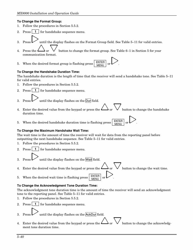
MX8000 Installation and Operation Guide
5–40
To Change the Format Group: 1. Follow the procedures in Section 5.5.2.
2. Press 1 for handshake sequence menu.
3. Press until the display flashes on the Format Group field. See Table 5–11 for valid entries.
4. Press the or button to change the format group. See Table 6–1 in Section 5 for your communication format.
5. When the desired format group is flashing press ENTER MENU or .
To Change the Handshake Duration Time: The handshake duration is the length of time that the receiver will send a handshake tone. See Table 5–11 for valid entries. 1. Follow the procedures in Section 5.5.2.
2. Press 1 for handshake sequence menu.
3. Press until the display flashes on the Dur field.
4. Enter the desired value from the keypad or press the or button to change the handshake duration time.
5. When the desired handshake duration time is flashing press ENTER MENU or .
To Change the Maximum Handshake Wait Time: The wait time is the amount of time the receiver will wait for data from the reporting panel before outputting the next handshake sequence. See Table 5–11 for valid entries. 1. Follow the procedures in Section 5.5.2.
2. Press 1 for handshake sequence menu.
3. Press until the display flashes on the Wait field.
4. Enter the desired value from the keypad or press the or button to change the wait time.
5. When the desired wait time is flashing press ENTER MENU or .
To Change the Acknowledgment Tone Duration Time: The acknowledgment tone duration time is the amount of time the receiver will send an acknowledgment tone to the reporting panel. See Table 5–11 for valid entries. 1. Follow the procedures in Section 5.5.2.
2. Press 1 for handshake sequence menu.
3. Press until the display flashes on the AckDur field.
4. Enter the desired value from the keypad or press the or button to change the acknowledg-ment tone duration time.

Section 5 – Programming
5–41
5.5.2.2 Pulse Format Select how this line card will handle pulse formats that are outside the standards for pulse format protocol.
To Select Which Format a 5-digit Pulse Format will be received as: 1. Follow the procedures in Section 5.5.2.
2. Press 2 for pulse format menu.
3. When the display flashes on the 5-digit Fmt field.
4. Select the format by pressing the or button.
5. When the desired wait time is flashing press ENTER MENU or .
To Select Which Format a 6-digit Pulse Format will be received as: 1. Follow the procedures in Section 5.5.2.
2. Press 2 for pulse format menu.
3. Press until the display flashes on the 6-digit Pulse Fmt field.
4. Select the format by pressing the or button.
5. When the desired wait time is flashing press ENTER MENU or .
To Select the Inter-Digit Time:
This option adjusts the time period between data blocks that the receiver will tolerate. 1. Follow the procedures in Section 5.5.2.
2. Press 2 for pulse format menu.
3. Press until the display flashes on the Timeout field. Note: When the Timeout field is set to 0 (recommended), the MX8000 uses an algorithm to determine the
inter-digit time. When set between 1 ms and 2000 ms, the time entered will be used.
4. Enter the desired value from the keypad or press the or button.
5. When the desired wait time is flashing press ENTER MENU or .
Set for 2300 and 1400 formats that require Acknowledgements on Even Rounds:
1. Follow the procedures in Section 5.5.2.
2. Press 2 for pulse format menu.
3. Press until the display flashes on the Ack/ Even field.
4. Select the format by pressing the or button.
5. When the desired wait time is flashing press ENTER MENU or .

MX8000 Installation and Operation Guide
5–42
Set for 3/1 and 4/1 Partially Extended Formats:
1. Follow the procedures in Section 5.5.2.
2. Press 2 for pulse format menu.
3. Press until the display flashes on the Partially Ex field.
4. Select the format by pressing the or button.
5. When the desired wait time is flashing press ENTER MENU or .
5.5.2.3 Line Options Line options is used to set the type of phone line, number of rings, country, and threshold voltage.
Note: Setting the number of rings to 0 disables the line device.
<Edit Line :01>3=Line Options4 Listen In5 Misc. Line Opt.
Direct=N Rings=002Country=USAThresh=08 Sample=08<Direct Cnct <=Exit>
¯
3
Figure 5–15: MX8000–LC3 Line Options Menu
How to Set the Line Card for a Direct Line (Dedicated Line): Note: This option must only be chosen for panels that have a direct connect capability. The panel supplies all line bias and a PBX is not required. This options sets the line card for a dedicated mode where the line is dedicated to the panel and normal timeouts will not occur. 1. Follow the procedures in Section 5.5.2.
2. Press 3 for Line Options menu.
3. The display will flash on the Direct field.
4. Press the or button to between Y for Yes, or N for No.
5. When the desired setting is flashing press ENTER MENU or .
To Change the Number of Rings, Follow These Steps: This controls the number of rings the line device needs to see before it will answer the call. 1. Follow the procedures in Section 5.5.2.
2. Press 3 for Line Options menu.
3. Press until the display flashes on the Rings field.
4. Enter the desired value from the keypad (000-255) or press the or button to change the number of rings before the receiver will answer. Note: Setting the number of rings to 0 disables the line device.
5. When the desired number of rings is flashing press ENTER MENU or .
Notes: • It is recommended that the number of rings is not set to a value greater than 5. • If Caller ID (see Section 5.5.2.5) is turned on the number of rings must be set to 2.

Section 5 – Programming
5–43
To Change Country:
The “Country” field selects the country of your choice. 1. Follow the procedures in Section 5.5.2.
2. Press 3 for Line Options menu.
3. Press until the display flashes on the Country field.
4. Press the or button to change the Country.
5. When the desired selection is flashing press ENTER MENU or .
To Change the Ring Threshold Voltage:
The “Threshold” field controls the phone line low voltage/Line Fault threshold level. If the voltage on the phone line connected to the line card drops below this set threshold level for that Device, the receiver will indicate a Line Fault on that phone line.
1. Follow the procedures in Section 5.5.2.
2. Press 3 for Line Options menu.
3. Press until the display flashes on the Thresh field.
4. Enter the desired value from the keypad or press the or button to change the Line fault threshold level. Values range from 1 to 15 volts in 2.75 VDC increments (1=2.75VDC, 2=5.5VDC, 3=8.25VDC and so on).
5. When the desired line fault threshold is flashing press ENTER MENU or .
To Change the Phone Line Sample Rate:
The sample field controls how often the receiver will sample the phone line to verify that it is above the set threshold level of that line card. This is how often the receiver verifies the integrity of the phone line. 1. Follow the procedures in Section 5.5.2.
2. Press 3 for Line Options menu.
3. Press until the display flashes on the Sample field.
4. Enter the desired value from the keypad or press the or button to change the line sample rate. Values range from 00 to 90 in 1 second increments (0=Line monitor disabled, 1=1 second, 2=2 seconds, 3=3 seconds and so on). The receiver will make two to three samples before generating a trouble condition on a faulty line.
5. When the desired sample time is flashing press ENTER MENU or .
6. Press to exit this menu.

MX8000 Installation and Operation Guide
5–44
5.5.2.4 Listen-In The listen in feature is used to perform two-way voice alarm verification between the central station and the alarm installation site. Note: See Section 4.7 on page 4–19 for a description of the listen-in modes.
To Change the Listen Mode:
1. Follow the procedures in Section 5.5.2.
2. Press 4 for the listen in options menu.
3. When the display shows the listen in options menu (see Figure 5–16):
<Edit Line :01>4=Listen In5 Misc. Line Opt.6 Ademco Auto Opt.
Mode=Not UsedTimeout=000<Account List><Listen Mode <=Exit>
¯
4
Figure 5–16: MX8000–LC3 Listen Mode Menu Display
Press the or button to change the listen mode setting.
4. When the desired setting is flashing press ENTER MENU .
To Change the PBX String: This option only appears if PBX is selected as the mode. 1. Follow the procedures in Section 5.5.2.
2. Press 4 for Listen In options menu.
3. Press until the display flashes on the <Str> field.
4. Press ENTER MENU .
5. Enter the desired numeric value from the keypad or press the or button to enter any special characters.
Table 5–13: Valid Programmable String Characters
Character Description
F Flash hook.
P Delay 500ms
, Delay 2 seconds
H Force a hang up of the line.
@ Detect dial tone.
t Check to see if the line is busy by looking for a busy tone.
0-9, *, #, A, B, C, D DTMF digits.
6. Press to move to the next character. or
7. Press ENTER MENU to enter the PBX string.
8. Select Y or N by pressing the or arrows. Y = Yes, erase or clear the PBX string. N = No, do not clear the PBX string, save the entered value.
Note: If Yes is selected the PBX string will be cleared and the “Clear String” option will revert to N (No).

Section 5 – Programming
5–45
To Change the Listen-In Timeout: Timeout is the amount of time Listen-in will remain active before timing out. Note: This setting will only have an affect if using the common mode. When using the PBX mode, the call is transferred to another number and the line card drops the call. 1. Follow the procedures in Section 5.5.2.
2. Press 4 for Listen In options menu.
3. Press until the display flashes on the <Timeout> field.
4. Enter the desired value from the keypad or press the or button to change the timeout setting. Values range from 0 to 255 in 1 second increments.
5. When the desired value is flashing press ENTER MENU .
To Edit the Listen-In Accounts Lists:
Note: The accounts lists apply to panels that do not send listen-in commands as a part of their message (Contact ID E606 or SIA LF and LE). Panels that send listen-in commands as part of their message do not need their account number in an account list. 1. Follow the procedures in Section 5.5.2.
2. Press 4 for Listen In options menu.
3. Press until the display flashes on the <Account List> field.
4. Press ENTER MENU .
Figure 5–17 shows the next display.
To Add a Listen-In Account Note: Panels that send listen-in commands (Contact ID E606 or SIA LF and LE) as part of their message do not need their account number in an account list.
1. Press 1 .
The display briefly shows the number (indicated by XX) of the lowest available listen in account number slot (20 total listen in account numbers [strings]). Adding # XX Note: The account numbers may contain wild card entries (* and #) described in Table 5–14. Therefore, the 20 account numbers are actually up to 20 unique strings.
Mode=Not UsedTimeout=000
<Listen Mode <=Exit>
<Listen In Accounts>1=Add Account2 Edit Account3 Clear Account ¯
<Account List>
1
ENTERMENU
Figure 5–17: MX8000–LC3 Listen In Accounts Menu
2. Enter the account number you wish to add to the listen in account list.
3. When the desired account number is flashing press ENTER MENU .
Table 5–14: Account Characters
Characters Description
0-9 Numeric entries
A-Z Alpha entries
* Alphanumeric wild card entry. Example: 123* = any account starting with 123.
# Numeric wild card entry. Example: # = 0 to 9. Example: 12345# = 123450 to 123459.

MX8000 Installation and Operation Guide
5–46
To Edit a Listen-In Account
1. Press 2 .
2. Press the or button until the desired listen in account is highlighted by the equal sign.
3. Press ENTER MENU .
4. Enter the revised account number you wish to the account list. See Table 5–14.
5. Press ENTER MENU .
Note: When editing an existing account it must be completely re-entered.
To Clear a Listen-In Account
1. Press 3 .
2. Press the or button until the desired listen in account is highlighted by the equal sign.
3. Press ENTER MENU .
The Display will read: < WARNING! > Delete Record No
4. Press the or button to toggle to Yes.
Note: Additional presses of the up or down arrow will toggle the choice between “yes” and “no”.
5. Press ENTER MENU .
5.5.2.5 Misc. Line Opt.
Some phone lines may use echo suppression, a billing delay feature, a hunt group or you may need to set various ring options. These miscellaneous phone options can be set through this programming menu.
To Change the Echo Suppress Setting:
If echo suppression is enabled (Y) a 2025Hz signal will be output for two seconds to disable echo suppression equipment. This option should be used only for panels that require a 2225Hz handshake. 1. Follow the procedures in Section 5.5.2.
<Edit Line :01>5 Misc. Line Opt.6 Ademco Auto Opt.7 Line Gain Opt.
Echo Spr=N Call ID=YBillDly=N HntGrp=00<Ring Opt> HngUp=120<Echo Suppress<=Exit>
5
Figure 5–18: MX8000–LC3 Miscellaneous Phone Line Options
2. Press 5 for Miscellaneous Line Options menu (see Figure 5–18).
The display Flashes on the Echo Spr= field.
3. Press the or button to change the echo suppress option from Y (Yes) to N (No) or vice versa.
4. When the setting is flashing press ENTER MENU .

Section 5 – Programming
5–47
How to Set Caller ID
Caller ID information is only sent if the incoming call has no data contained in it.
Notes: Caller ID to Automation – When enabled, Caller ID information is output to the automation system only in the event that no alarm data is received from a security system control panel.
Caller ID to Printer Ports – When enabled, Caller ID information is output to the printer port(s) for every call received at the time that the Caller ID information is available from the Public Switched Telephone Network (normally between the first and second ring.) This option should only be used when connected to a parallel or serial printer or equivalent.
1. Follow the procedures in Section 5.5.2.
2. Press 5 for Miscellaneous Line Options menu (see Figure 5–18).
The display Flashes on the Echo Spr= field.
3. Press until the display flashes on the Call ID field.
4. Press the or button to change the caller ID option from Y (Yes) to N (No) or vice versa.
5. When the setting is flashing press ENTER MENU .
To Change the Billing Delay Setting:
If billing delay is enabled (Y), a delay of two seconds will be inserted at the beginning of each incoming call. 1. Follow the procedures in Section 5.5.2.
2. Press 5 for Miscellaneous Line Options menu.
3. Press until the display flashes on the BillDly field.
4. Press the or button to toggle the billing delay between “Yes” or “No”.
5. When the desired setting is flashing press ENTER MENU .
To Change the Hunt Group:
Note: If a Hunt Group number is assigned to a line that has a virtual line number assigned, the Hunt Group Number will take precedence and the virtual line and receiver numbers will be ignored.
1. Follow the procedures in Section 5.5.2.
2. Press 5 for Miscellaneous Line Options menu.
3. Press until the display flashes on the HntGrp field.
4. Enter the desired value from the keypad or press the or button to change the hunt group number.
Notes:
• If using the ADEMCO 685 or ADEMCO 685 CAPS Automation Protocol, valid entries are 00 through 08.
• If using the CP-220 Automation Protocol, valid entries are 00 through 09 or 65 (A) through 70 (F). Keypad entries for A through F are provided in Table 5–10 on page 5–23.

MX8000 Installation and Operation Guide
5–48
5. When the desired hunt group is flashing press ENTER MENU .
6. To exit press .
To Change the Ring Options:
Note: The default ring options will function for most installations and will not need to be changed.
The ring options menu items (Figure 5–19) have the following meanings:
MinR (Minimum Ring Period) – This value is the minimum ringer frequency that is accepted as a valid. A valid ring frequency must fall between the Minimum Ring Period and the Maximum Ring Period.
Max (Maximum Ring Period) – This value is the maximum ringer frequency that is accepted as a valid. A valid ring frequency must fall between the Minimum Ring Period and the Maximum Ring Period.
MinR=40 Max=060ROff=4000 MinO=450RErr=2200 Min#=05<Min Ring Period ms
<Edit Line :01>5 Misc. Line Opt.6 Ademco Auto Opt.7 Line Gain Opt.
Echo Spr=N Call ID=YBillDly=N HntGrp=00<Ring Opt> HngUp=120<Echo Suppress<=Exit>
5
Figure 5–19: MX8000–LC3 Ring Options
ROff (Ringer Off Time) –- This value is the normal amount of time between rings on the local phone system. If the value entered in this field is too large for your local phone system, it may cause the system to miss the beginning of Caller ID information.
Min (Minimum Ringer Off Time) – Caller ID information is normally sent between the first and second ring. On some phone systems the first ring is sent in 2 bursts with a short pause in between. For proper handling of caller ID the system needs to be able to determine that these 2 bursts are one ring. The Minimum Ringer Off Time is used to determine what the minimum interval is between rings so that the system will treat two burst separated by a brief pause as one ring.
RErr (Ringer Off Error) – To determine when a new call is received, the system will add the value of ROff, Min, and this value. When the length of time since the last ring exceeds this sum, the ring will be considered as a new call. This field is used to enter the amount of time to be added to ROff and Min when determining if a ring is a new call.
Min# (Minimum Number of Ringer Periods – This field is used to define the number of valid rings that must be received before the system accepts the call as valid (answers).
To Change the Ring Options: 1. Follow the procedures in Section 5.5.2.
2. Press 5 for Miscellaneous Line Options menu.
3. Press until the display flashes on the <Ring Opt> field.
4. Press ENTER MENU .
5. The display flashes on the Minimum Ring Period (MinR) field. 6. Enter a value from 15 to 99 ms for the Minimum Ring Period.
7. Press to advance to the Max Ring Period (Max) field. 8. Enter a value from 015 to 100 ms for the Maximum Ring Period.
9. Press to advance to the Ringer Off Time (ROff) field. 10. Enter a value from 1500 to 8000 ms for the Ringer Off Time.
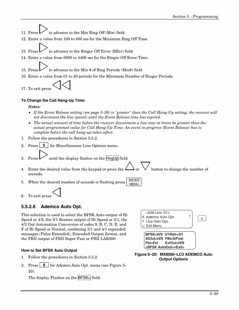
Section 5 – Programming
5–49
11. Press to advance to the Min Ring Off (Min) field.
12. Enter a value from 100 to 800 ms for the Minimum Ring Off Time.
13. Press to advance to the Ringer Off Error (RErr) field.
14. Enter a value from 0800 to 4400 ms for the Ringer Off Error Time.
15. Press to advance to the Min # of Ring Periods (Min#) field.
16. Enter a value from 01 to 20 periods for the Minimum Number of Ringer Periods.
17. To exit press .
To Change the Call Hang-Up Time:
Notes: • If the Event Release setting (see page 5–26) is "greater" than the Call Hang-Up setting, the receiver will
not disconnect the line (panel) until the Event Release time has expired. • The actual amount of time before the receiver disconnects a line may at times be greater than the
actual programmed value for Call Hang-Up Time. An event in progress (Event Release) has to complete before the call hang-up takes affect.
1. Follow the procedures in Section 5.5.2.
2. Press 5 for Miscellaneous Line Options menu.
3. Press until the display flashes on the HngUp field.
4. Enter the desired value from the keypad or press the or button to change the number of seconds.
5. When the desired number of seconds is flashing press ENTER MENU .
6. To exit press .
5.5.2.6 Ademco Auto Opt.
This selection is used to select the BFSK Auto output of Hi Speed or 4/2, the 3/1 Restore output of Hi Speed or 3/1, the 4/2 Out Automation Conversion of codes 9, B, C, D, E, and F of Hi Speed or Normal, combining 3/1 and 4/1 expanded messages (Pulse Extended), Extended Output format, and the FBII output of FBII Super Fast or FBII LAR300.
How to Set BFSK Auto Output
1. Follow the procedures in Section 5.5.2.
2. Press 6 for Ademco Auto Opt. menu (see Figure 5–
20).
The display Flashes on the BFSK= field.
6 Ademco Auto Opt.7 Line Gain Opt.
BFSK=H/S 3/1Rstr=3/142Out=H/S FBI=S/Fast
<BFSK AutoOut<=Exit>
6
<Edit Line :01>
Pls=Ext ExtOut=H/S
< Exit Menu
Figure 5–20: MX8000–LC3 ADEMCO Auto Output Options

MX8000 Installation and Operation Guide
5–50
3. Press the or button to change the option from HiSpeed to 4/2 or vice versa.
4. When the desired setting is flashing press ENTER MENU .
How to Set 3/1 Restore Output
1. Follow the procedures in Section 5.5.2.
2. Press 6 for Ademco Auto Opt. menu (see Figure 5–20).
3. Press the button. The display Flashes on the 3/1 Rstr= field.
4. Press the or button to change the option from HiSpeed to 3/1 or vice versa.
5. When the desired setting is flashing press ENTER MENU .
How to Set 4/2 Out 1. Follow the procedures in Section 5.5.2.
2. Press 6 for Ademco Auto Opt. menu (see Figure 5–20).
3. Press . The display Flashes on the 42Out= field.
4. Press the or button to change the option from HiSpeed to Normal or vice versa.
5. When the desired setting is flashing press ENTER MENU .
6. To exit press .
How to Set FBII Out 1. Follow the procedures in Section 5.5.2.
2. Press 6 for Ademco Auto Opt. menu (see Figure 5–20).
3. Press . The display Flashes on the FBI= field.
4. Press the or button to change the option from S/Fast to LAR300 or vice versa.
5. When the desired setting is flashing press ENTER MENU .
6. To exit press .
How to Set Pulse Extended 1. Follow the procedures in Section 5.5.2.
2. Press 6 for Ademco Auto Opt. menu (see Figure 5–20).

Section 5 – Programming
5–51
3. Press . The display Flashes on the Pls= field.
4. Press the or button to change the option from Extended to Not Extended or vice versa.
5. When the desired setting is flashing press ENTER MENU .
6. To exit press .
How to Set Extended Output
Note: This field will only be active when the Pulse Extended option above has been set to Extended. 1. Follow the procedures in Section 5.5.2.
2. Press 6 for Ademco Auto Opt. menu (see Figure 5–20).
3. Press . The display Flashes on the ExtOut= field.
4. Press the or button to change the option from High Speed to 4/2 or vice versa.
5. When the desired setting is flashing press ENTER MENU .
6. To exit press .
5.5.2.7 Line Gain Opt. This selection is used to select the gain for transmit and receive for a line.
How to Set Transmit Gain
1. Follow the procedures in Section 5.5.2.
2. Press 7 for Line Gain Opt. menu (see Figure 5–21).
The display Flashes on the Xmit= field.
3. Press the or button to change the transmit gain.
7 Line Gain Opt.
Xmit=-8db Rec=6db
<TransmitGain<=Exit>
7
<Edit Line :01>
< Exit Menu
OHGain=7.0db RImp=HIMon=Norm Gain=2.0db
Figure 5–21: MX8000–LC3 Line Gain Options
4. When the desired setting is flashing press ENTER MENU .
How to Set Receive Line Gain
1. Follow the procedures in Section 5.5.2.
2. Press 7 for Line Gain Opt. menu (see Figure 5–21).
3. Press the button. The display Flashes on the Rec= field.
4. Press the or button to change the receive gain.

MX8000 Installation and Operation Guide
5–52
5. When the desired setting is flashing press ENTER MENU .
6. To exit press .
How to Set CID Monitor
Caller ID Monitor allows the selection of different modes for decoding Caller ID. These are:
• Normal (or standard) where the detection method is first ring, delay, preamble, marks, and then Caller ID data.
• Preamble where the Caller ID chip looks for preamble data prior to Caller ID.
• DTMF where the system looks for DTMF based Caller ID data. (This is a non-standard method of Caller ID.
• Marks where the Caller ID chip looks for a Marks signal prior to the Caller ID data.
Note: This option is will only be applicable when Caller ID has been selected.
1. Follow the procedures in Section 5.5.2.
2. Press 7 for Line Gain Opt. menu (see Figure 5–21).
3. Press the .
The display Flashes on the Mon= field.
4. Press the or button to change the CID monitor.
5. When the desired setting is flashing press ENTER MENU .
6. To exit press .
How to Set CID Gain
Caller ID gain sets the gain of the Caller ID receive logic.
Note: This option is will only be applicable when Caller ID has been selected.
1. Follow the procedures in Section 5.5.2.
2. Press 7 for Line Gain Opt. menu (see Figure 5–21).
3. Press the .
The display Flashes on the Gain= field.
4. Press the or button to change the CID Gain.
5. When the desired setting is flashing press ENTER MENU .
6. To exit press .

Section 5 – Programming
5–53
How to Set On Hook Gain
On hook gain sets the analog receive Caller ID gain prior to line pickup.
Note: This option is will only be applicable when Caller ID has been selected.
1. Follow the procedures in Section 5.5.2.
2. Press 7 for Line Gain Opt. menu (see Figure 5–21).
3. Press the .
The display Flashes on the OHGain= field.
4. Press the or button to change the On Hook Gain.
5. When the desired setting is flashing press ENTER MENU .
6. To exit press .
How to Set Ringer Impedance
Ringer Impedance allows the impedance the Caller ID chip presents to the phone line to be set for either High or Synthesize.
Note: This option is will only be applicable when Caller ID has been selected.
1. Follow the procedures in Section 5.5.2.
2. Press 7 for Line Gain Opt. menu (see Figure 5–21).
3. Press the .
The display Flashes on the RImp= field.
4. Press the or button to change the Ringer Impedance.
5. When the desired setting is flashing press ENTER MENU .
6. To exit press .
5.5.3 Edit Line – MX8000–LRR To edit an existing Line, follow these steps: 1. Log on to the receiver. (See Section 4.4.4 for log on procedure.)
2. Press ENTER MENU button.
3. Press 7 for program menu.
The display will briefly display Initializing Please wait . . .
4. Press 2 to choose Line Device menu.
5. Press 2 to select MX8000–LRR.

MX8000 Installation and Operation Guide
5–54
6. Press 2 to edit Line.
The display will show a list of the existing Lines.
7. Press the or arrow buttons to move through the available list.
8. When the equal sign highlights the Line you wish to edit:
Press ENTER MENU .
The display will show the Radio Line Card Options selection screen. (See Figure 5–22.)
9. Press 1 to select Radio LC Options.
<Edit Line :34>1 Radio LC Options< Exit Menu
1
<Edit Line>L34=MX8000-LRR < Exit Menu
Cent Stat#=17O/E Net=Even VPN=NoA/B Net=A Mon=No<Cent Stat# <=Exit>
ENTERMENU
Figure 5–22: MX8000–LRR Line Edit
An edit screen is displayed that allows the Central Station number to be changed, Odd/Even Parity, Virtual Private, and A/B networks to be defined, and monitor stations to be enabled.
How to Set Central Station # (LRR Receiver ID)
1. Follow the procedures in Section 5.5.2.7.
The display Flashes on the Cent Stat#= field.
2. Press the or button to change the number or enter the number from the keypad. The number can be from 001 to 255.
Note: A central station number supplied by AlarmNet is in hexadecimal format. Use Table 5–15 on page 5–55 to convert the hexadecimal AlarmNet number into the decimal number that is entered into the MX8000.
3. When the desired number is flashing press ENTER MENU .
How to Set Odd/Even Network 1. Follow the procedures in Section 5.5.2.7.
2. Press the button. The display Flashes on the O/E Net= field.
3. Press the or button to change the option from Odd to Even or vice versa.
4. When the desired setting is flashing press ENTER MENU .
How to Set VPN (Virtual Private Network)
1. Follow the procedures in Section 5.5.2.7.
2. Press . The display Flashes on the VPN= field. Notes: • When using the VPN feature with ADEMCO 8000 automation protocol, the LRR card must be
installed in slot 12. • When using the VPN feature with 685 or CAPS automation protocol and NOT using Virtual
Receiver/Line numbers, the LRR card must be installed in slot 3 (see page 1–6). • When using the VPN feature with 685 or CAPS automation protocol and WITH Virtual Receiver/Line
numbers, assign the card as line 8.

Section 5 – Programming
5–55
3. Press the or button to change the option from No to Yes or vice versa.
4. When the desired setting is flashing press ENTER MENU .
Table 5–15: Hexadecimal AlarmNet Number to Decimal Conversion
HEX DEC HEX DEC HEX DEC HEX DEC HEX DEC HEX DEC HEX DEC HEX DEC 1 1 21 33 41 65 61 97 1 129 21 161 41 193 61 225
2 2 22 34 42 66 62 98 2 130 22 162 42 194 62 226
3 3 23 35 43 67 63 99 3 131 23 163 43 195 63 227
4 4 24 36 44 68 64 100 4 132 24 164 44 196 64 228
5 5 25 37 45 69 65 101 5 133 25 165 45 197 65 229
6 6 26 38 46 70 66 102 6 134 26 166 46 198 66 230
7 7 27 39 47 71 67 103 7 135 27 167 47 199 67 231
8 8 28 40 48 72 68 104 8 136 28 168 48 200 68 232
9 9 29 41 49 73 69 105 9 137 29 169 49 201 69 233
A 10 2A 42 4A 74 6A 106 A 138 2A 170 4A 202 6A 234
B 11 2B 43 4B 75 6B 107 B 139 2B 171 4B 203 6B 235
C 12 2C 44 4C 76 6C 108 C 140 2C 172 4C 204 6C 236
D 13 2D 45 4D 77 6D 109 D 141 2D 173 4D 205 6D 237
E 14 2E 46 4E 78 6E 110 E 142 2E 174 4E 206 6E 238
F 15 2F 47 4F 79 6F 111 F 143 2F 175 4F 207 6F 239
10 16 30 48 50 80 70 112 10 144 30 176 50 208 70 240
11 17 31 49 51 81 71 113 11 145 31 177 51 209 71 241
12 18 32 50 52 82 72 114 12 146 32 178 52 210 72 242
13 19 33 51 53 83 73 115 13 147 33 179 53 211 73 243
14 20 34 52 54 84 74 116 14 148 34 180 54 212 74 244
15 21 35 53 55 85 75 117 15 149 35 181 55 213 75 245
16 22 36 54 56 86 76 118 16 150 36 182 56 214 76 246
17 23 37 55 57 87 77 119 17 151 37 183 57 215 77 247
18 24 38 56 58 88 78 120 18 152 38 184 58 216 78 248
19 25 39 57 59 89 79 121 19 153 39 185 59 217 79 249
1A 26 3A 58 5A 90 7A 122 1A 154 3A 186 5A 218 7A 250
1B 27 3B 59 5B 91 7B 123 1B 155 3B 187 5B 219 7B 251
1C 28 3C 60 5C 92 7C 124 1C 156 3C 188 5C 220 7C 252
1D 29 3D 61 5D 93 7D 125 1D 157 3D 189 5D 221 7D 253
1E 30 3E 62 5E 94 7E 126 1E 158 3E 190 5E 222 7E 254
1F 31 3F 63 5F 95 7F 127 1F 159 3F 191 5F 223 7F 255
20 32 40 64 60 96 0 128 20 160 40 192 60 224
NOTE: The most significant bit in the MX8000 is suppressed. Entries of decimal 80 through 255 equate to hexadecimal 0 through 7F.
How to Set A/B Network
1. Follow the procedures in Section 5.5.2.7.
2. Press .
The display Flashes on the A/B Net= field.
3. Press the or button to change the option from A to B or vice versa.
4. When the desired setting is flashing press ENTER MENU .

MX8000 Installation and Operation Guide
5–56
How to Set Monitor Station 1. Follow the procedures in Section 5.5.2.7.
2. Press .
The display Flashes on the Mon= field.
3. Press the or button to change the option from Yes to No or vice versa.
4. When the desired setting is flashing press ENTER MENU .
5. To exit press .
5.5.4 Edit Line – MX8000–LC1 (1 Line) To edit an existing Line Device, follow these steps:
1. Log on to the receiver. (See Section 4.4.4 for log on procedure.)
2. Press ENTER MENU button.
3. Press 7 for program menu.
The display will briefly display Initializing Please wait . . .
4. Press 2 to choose Line Device menu.
5. Press 3 to select MX8000–LC1 (1 Line)
6. Press 2 to edit Line.
The display will show a list of the existing Lines.
7. Press the or arrow buttons to move through the available list.
8. When the equal sign is on the Line you wish to edit:
Press ENTER MENU . The display will show a list of choices. Table 5–16 lists these choices and provides a brief
description.
Table 5–16: MX8000–LC1 Edit Line List Items and Description
Edit Line List Description
1 Handshake Seq This function is used to program the handshake order and parameters for this Line.
2 Pulse Format Used to set the 5- and 6-digit format, Interdigit timeout, acknowledgement, and to select if partially extended is enabled.
3 Line Options Used to set number of rings, ring on/off duration, threshold voltage, and sample time.
4 Listen In Used to program the parameters for the listen in (two-way voice communication) feature if used. Must not be used in UL installations.
5 Misc. Line Opt. Used to program hunt group number, enable or disable echo suppression, and billing delay.
6 Ademco Auto Opt Used to select the BFSK auto output, 3/1 restore output, pulse output, and FBII output.

Section 5 – Programming
5–57
5.5.4.1 Handshake Sequence Each line card is intelligent enough to determine what format is being sent from a reporting panel. You only need to program the handshake order and parameters for each line. A line will initiate up to six different types of handshake tone groups. The order in which the receiver sends out these handshake signals can be changed in this program location for each line card. Table 6–1 in Section 6 lists the proper handshake to use for the type of communication format you are using with a panel.
Follow these steps to change the handshake order and or the parameters associated with the handshake.
Delay=002 Dur=010 Wait=025 AckDur=080 <Seq # <=Exit>
<Edit Line: 01>1=Handshake Seq.2 Pulse Format3 Line Options ¯
Hs=1 Gr=1400_2300–2
1
Figure 5–23: MX8000–LC1 Handshake Sequence Menu
To Change the Handshake Sequence Number: Handshake sequence sets the order in which the receiver will send out handshakes. 1. Follow the procedures in Section 5.5.4.
2. Press 1 for handshake sequence menu.
When display flashes on the Hs# (see Figure 5–23).
3. Press the or button to change the ordered handshake number. 1 = the first handshake tone sent 2 = the second handshake tone to be sent and so on.
Delay=002 Dur=010 Wait=025 AckDur=080 <Seq # <=Exit>
Hs=1 Gr=1400_2300–2
Figure 5–24: MX8000–LC1 Handshake Order Number
4. When the desired order number is flashing press ENTER MENU or .
The display will start flashing the format group field.
To Change the Format Group: 1. Follow the procedures in Section 5.5.4.
2. Press 1 for handshake sequence menu.
3. Press until the display flashes on the Format Group field. See Table 5–11 for valid entries.
4. Press the or button to change the format group. See Table 6–1 in Section 6 for your communication format.
5. When the desired format group is flashing press ENTER MENU or .
To Change the Handshake Delay Time: This is the duration of time that the receiver will wait before it sends its handshake tone. See Table 5–11 for valid entries. 1. Follow the procedures in Section 5.5.4.
2. Press 1 for handshake sequence menu.
3. Press until the display flashes on the Delay field.

MX8000 Installation and Operation Guide
5–58
4. Enter the desired value from the keypad or press the or button to change the delay time.
5. When the desired handshake delay time is flashing press ENTER MENU or .
To Change the Handshake Duration Time:
The handshake duration is the length of time that the receiver will send a handshake tone. See Table 5–11 for valid entries. 1. Follow the procedures in Section 5.5.4.
2. Press 1 for handshake sequence menu.
3. Press until the display flashes on the Dur field.
4. Enter the desired value from the keypad or press the or button to change the handshake duration time.
5. When the desired handshake duration time is flashing press ENTER MENU or .
To Change the Maximum Handshake Wait Time:
The wait time is the amount of time the receiver will wait for data from the reporting panel before outputting the next handshake sequence. See Table 5–11 for valid entries. 1. Follow the procedures in Section 5.5.4.
2. Press 1 for handshake sequence menu.
3. Press until the display flashes on the Wait field.
4. Enter the desired value from the keypad or press the or button to change the wait time.
5. When the desired wait time is flashing press ENTER MENU or .
To Change the Acknowledgment Tone Duration Time:
The acknowledgment tone duration time is the amount of time the receiver will send an acknowledgment tone to the reporting panel. See Table 5–11 for valid entries. 1. Follow the procedures in Section 5.5.4.
2. Press 1 for handshake sequence menu.
3. Press until the display flashes on the AckDur field.
4. Enter the desired value from the keypad or press the or button to change the acknowledg-ment tone duration time.

Section 5 – Programming
5–59
5.5.4.2 Pulse Format Select how this line card will handle pulse formats that are outside the standards for pulse format protocol.
To Select Which Format a 5-digit Pulse Format will be received as: 1. Follow the procedures in Section 5.5.4.
2. Press 2 for pulse format menu.
3. Press until the display flashes on the 5-digit Fmt field.
4. Select the format by pressing the or button.
5. When the desired wait time is flashing press ENTER MENU or .
To Select Which Format a 6-digit Pulse Format will be received as: 1. Follow the procedures in Section 5.5.4.
2. Press 2 for pulse format menu.
3. Press until the display flashes on the 6-digit Pulse Fmt field.
4. Select the format by pressing the or button.
5. When the desired wait time is flashing press ENTER MENU or .
To Select the Inter-Digit Time: This option adjusts the time period between data blocks that the receiver will tolerate. 1. Follow the procedures in Section 5.5.4.
2. Press 2 for pulse format menu.
3. Press until the display flashes on the Timeout field. Note: When the Timeout field is set to 0 (recommended), the MX8000 uses and algorithm to determine the
inter-digit time. When set between 1 ms and 2000 ms, the time entered will be used.
4. Enter the desired value from the keypad or press the or button.
5. When the desired wait time is flashing press ENTER MENU or .
Set for 2300 and 1400 formats that require Acknowledgements on Even Rounds: 1. Follow the procedures in Section 5.5.4.
2. Press 2 for pulse format menu.
3. Press until the display flashes on the Ack/Even field.
4. Select the format by pressing the or button.
5. When the desired wait time is flashing press ENTER MENU or .

MX8000 Installation and Operation Guide
5–60
Set for 3/1 and 4/1 Partially Extended Formats: 1. Follow the procedures in Section 5.5.4.
2. Press 2 for pulse format menu.
3. Press until the display flashes on the Part Ex field.
4. Select the format by pressing the or button.
5. When the desired wait time is flashing press ENTER MENU or .
5.5.4.3 Line Options Line options is used to set the type of phone line, number of ring, ring on/off duration, threshold voltage, and sample time. Note: Setting the number of rings to 0 disables the line device.
<Edit Line :01> 3=Line Options4 Listen In5 Misc. Line Opt.
Direct=N Rings=002On=010 Off=010 dB=MdThresh=08 Sample=020<Direct Cnct <=Exit>
¯
3
Figure 5–25: MX8000–LC1 Line Options Menu
How to Set the Line Card for a Direct Line (Dedicated Line): Note: This option must only be chosen for panels that have a direct connect capability. The panel supplies all line bias and a PBX is not required. This options sets the line card for a dedicated mode where the line is dedicated to the panel and normal timeouts will not occur. 1. Follow the procedures in Section 5.5.4.
2. Press 3 for Line Options menu.
3. The display will flash on the Direct field.
4. Press the or button to between Y for Yes, or N for No.
5. When the desired setting is flashing press ENTER MENU or .
To Change the Number of Rings, Follow These Steps: This controls the number of rings the receiver needs to see before it will answer the call. 1. Follow the procedures in Section 5.5.4.
2. Press 3 for Line Options menu.
3. The display will flash on the Rings field.
4. Enter the desired value from the keypad (000-255) or press the or button to change the number of rings before the receiver will answer. Note: Setting the number of rings to 0 disables the line device.
5. When the desired number of rings is flashing press ENTER MENU or .
Notes: • It is recommended that the number of rings is not set to a value greater than 5. • If Caller ID (see Section 5.5.4.5) is turned on the number of rings must be set to 2.

Section 5 – Programming
5–61
To Change the Ring On Time:
The “On” field controls the ring on time. The ring on time is the length of time the receiver will listen to a ring prior to recognizing it as a ring. 1. Follow the procedures in Section 5.5.4.
2. Press 3 for Line Options menu.
3. Press until the display flashes on the On field.
4. Enter the desired value from the keypad or press the or button to change the ring on time. Values range from 0 to 255 in increments of 50ms (1=50ms, 2=100ms, 3=150ms and so on).
5. When the desired ring on time is flashing press ENTER MENU or .
To Change the Ring Off Time:
The “Off” field controls the ring off time. The ring off time is the length of time the receiver will recognize an “Off” ring voltage. 1. Follow the procedures in Section 5.5.4.
2. Press 3 for Line Options menu.
3. Press until the display flashes on the Off field.
4. Enter the desired value from the keypad or press the or button to change the ring off time. Values range from 0 to 255 in increments of 50ms (1=50ms, 2=100ms, 3=150ms and so on).
5. When the desired ring off time is flashing press ENTER MENU or .
To Select the dB Level:
This option selects the dB level of the handshake and acknowledge tone of the Line Device being programmed. 1. Follow the procedures in Section 5.5.4.
2. Press 3 for Line Options menu.
3. Press until the display flashes on the dB field.
4. Press the or button to change the dB level of the handshake and acknowledge tone. Lo (Low) = -11dBm, Md (Medium) = -10dBm, Hi (High) = -9dBm.
5. When the setting is flashing press ENTER MENU or .
To Change the Ring Threshold Voltage:
The “Threshold” field controls the phone line low voltage/Line Fault threshold level. If the voltage on the phone line connected to the line card drops below this set threshold level for that Line Device, the receiver will indicate a Line Fault on that phone line. 1. Follow the procedures in Section 5.5.4.
2. Press 3 for Line Options menu.

MX8000 Installation and Operation Guide
5–62
3. Press until the display flashes on the Thresh field.
4. Enter the desired value from the keypad or press the or button to change the Line fault threshold level. Values range from 1 to 15 volts in 2.0 VDC increments (1=2.0VDC, 2=4.0VDC, 3=6.0VDC and so on).
5. When the desired line fault threshold is flashing press ENTER MENU or .
To Change the Phone Line Sample Rate: The sample time field controls how often the receiver will sample the phone line to verify that it is above the set threshold level of that line card. This is how often the receiver verifies the integrity of the phone line. 1. Follow the procedures in Section 5.5.4.
2. Press 3 for Line Options menu.
3. Press until the display flashes on the Sample field.
4. Enter the desired value from the keypad or press the or button to change the line sample rate. Values range from 0 to 255 in 1 second increments (0=Line monitor disabled, 1=1 second, 2=2 seconds, 3=3 seconds and so on). The receiver will make two to three samples before generating a trouble condition on a faulty line.
5. When the desired sample time is flashing press ENTER MENU or .
6. Press to exit this menu.
5.5.4.4 Listen-In The listen in feature is used to perform two-way voice alarm verification between the central station and the alarm installation site. Note: See Section 4.7 on page 4–19 for a description of the listen-in modes.
To Change the Listen Mode: 1. Follow the procedures in Section 5.5.4.
2. Press 4 for the listen in options menu.
3. When the display shows the listen in options menu (see Figure 5–26):
<Edit Line :01>4=Listen In5 Misc. Line Opt.< Exit Menu
Mode=Not UsedTimeout=000<Account List><Listen Mode <=Exit>
4
Figure 5–26: MX8000–LC1 Listen Mode Menu Display
Press the or button to change the listen mode setting.
4. When the desired setting is flashing press ENTER MENU .
To Change the PBX String: This option only appears if PBX is select as the mode. 1. Follow the procedures in Section 5.5.4.
2. Press 4 for Listen In options menu.

Section 5 – Programming
5–63
3. Press until the display flashes on the <Str> field.
4. Press ENTER MENU .
5. Enter the desired numeric value from the keypad or press the or button to enter any special characters. (See Table 5–13, page 5–44 for valid programmable string characters.)
6. Press to move to the next character. or
7. Press ENTER MENU to enter the PBX string.
8. Select Y or N by pressing the or arrows. Y = Yes, erase or clear the PBX string. N = No, do not clear the PBX string, save the entered value.
Note: If Yes is selected the PBX string will be cleared and the “Clear String” option will revert to N (No).
To Change the Listen-In Timeout:
Timeout is the amount of time Listen-in will remain active before timing out.
Note: This setting will only have an affect if using the common mode. When using the PBX mode, the call is transferred to another number and the line card drops the call. 1. Follow the procedures in Section 5.5.4.
2. Press 4 for Listen In options menu.
3. Press until the display flashes on the <Timeout> field.
4. Enter the desired value from the keypad or press the or button to change the timeout setting. Values range from 0 to 255 in 1 second increments.
5. When the desired value is flashing press ENTER MENU .
To Edit the Listen-In Accounts Lists: Note: The accounts lists apply to panels that do not send listen-in commands as a part of their message (Contact ID E606 or SIA LF and LE). Panels that send listen-in commands as part of their message do not need their account number in an account list.
1. Follow the procedures in Section 5.5.4.
2. Press 4 for Listen In options menu.
3. Press until the display flashes on the <Account List> field.
4. Press ENTER MENU .
Figure 5–27 shows the next display.

MX8000 Installation and Operation Guide
5–64
To Add a Listen-In Account Note: Panels that send listen-in commands (Contact ID E606 or SIA LF and LE) as part of their message do not need their account number in an account list.
1. Press 1 .
The display briefly shows the number (indicated by XX) of the lowest available listen in account number slot (20 total listen in account numbers [strings]). Adding # XX Note: The account numbers may contain wild card entries (* and #) described in Table 5–14. Therefore, the 20 account numbers are actually up to 20 unique strings.
Mode=Not UsedTimeout=000
<Listen Mode <=Exit>
<Listen In Accounts>1=Add Account2 Edit Account3 Clear Account ¯
<Account List>
1
ENTERMENU
Figure 5–27: MX8000–LC1 Listen In Accounts Menu
2. Enter the account number you wish to add to the listen in account list.
3. When the desired account number is flashing press ENTER MENU .
To Edit a Listen-In Account
1. Press 2 .
2. Press the or button until the desired listen in account is highlighted by the equal sign.
3. Press ENTER MENU .
4. Enter the revised account number you wish to the account list. See Table 5–14 on page 5–45.
5. Press ENTER MENU .
Note: When editing an existing account it must be completely re-entered.
To Clear a Listen-In Account
1. Press 3 .
2. Press the or button until the desired listen in account is highlighted by the equal sign.
3. Press ENTER MENU .
The Display will read: < WARNING! > Delete Record No
4. Press the or button to toggle to Yes.
Note: Additional presses of the up or down arrow will toggle the choice between “yes” and “no”.
5. Press ENTER MENU .

Section 5 – Programming
5–65
5.5.4.5 Misc. Line Opt. Some phone lines may use echo suppression, a billing delay feature, a hunt group or you may need to set various ring options. These miscellaneous phone options can be set through this programming menu.
<Edit Line :01>5 Misc. Line Opt.< Exit Menu
Echo Spr=N Call ID=YBillDly=N HntGrp=00
<Echo Suppress<=Exit>
5
HngUp=120
Figure 5–28: MX8000–LC1 Miscellaneous Phone Line Options
To Change the Echo Suppress Setting:
If echo suppression is enabled (Y) a 2025Hz signal will be output for two seconds to disable echo suppression equipment. This option should be used only for panels that require a 2225Hz handshake. 1. Follow the procedures in Section 5.5.4.
2. Press 5 for Miscellaneous Line Options menu (see Figure 5–28).
The display Flashes on the Echo Spr= field.
3. Press the or button to change the echo suppress option from Y (Yes) to N (No) or vice versa.
4. When the setting is flashing press ENTER MENU .
How to Set Caller ID
Caller ID information is only sent if the incoming call has no data contained in it.
Notes: Caller ID to Automation – When enabled, Caller ID information is output to the automation system only in the event that no alarm data is received from a security system control panel.
Caller ID to Printer Ports – When enabled, Caller ID information is output to the printer port(s) for every call received at the time that the Caller ID information is available from the Public Switched Telephone Network (normally between the first and second ring.) This option should only be used when connected to a parallel or serial printer or equivalent.
1. Follow the procedures in Section 5.5.4.
2. Press 5 for Miscellaneous Line Options menu (see Figure 5–28).
The display Flashes on the Echo Spr= field.
3. Press until the display flashes on the Call ID field.
4. Press the or button to change the caller ID option from Y (Yes) to N (No) or vice versa.
5. When the setting is flashing press ENTER MENU .
To Change the Billing Delay Setting:
If billing delay is enabled (Y), a delay of two seconds will be inserted at the beginning of each incoming call.
1. Follow the procedures in Section 5.5.4.
2. Press 5 for Miscellaneous Line Options menu.

MX8000 Installation and Operation Guide
5–66
3. Press until the display flashes on the BillDly field.
4. Press the or button to toggle the billing delay between “Yes” or “No”.
5. When the desired setting is flashing press ENTER MENU .
To Change the Hunt Group:
Note: If a Hunt Group number is assigned to a line that has a virtual line number assigned, the Hunt Group Number will take precedence and the virtual line and receiver numbers will be ignored.
1. Follow the procedures in Section 5.5.4.
2. Press 5 for Miscellaneous Line Options menu.
3. Press until the display flashes on the HntGrp field.
4. Enter the desired value from the keypad or press the or button to change the hunt group number.
Notes:
• If using the ADEMCO 685 Automation Protocol, valid entries are 00 through 08.
• If using the CP-220 Automation Protocol, valid entries are 00 through 09 or 66 (B) through 70 (F). Keypad entries for B through F are provided in Table 5–10 on page 5–23.
5. When the desired hunt group is flashing press ENTER MENU .
6. To exit press .
To Change the Call Hang-Up Time:
Notes:
• If the Event Release setting (see page 5–26) is "greater" than the Call Hang-Up setting, the receiver will not disconnect the line (panel) until the Event Release time has expired.
• The actual amount of time before the receiver disconnects a line may at times be greater than the actual programmed value for C Hang-Up Time. An event in progress (Event Release) has to complete before the call hang-up takes affect.
1. Follow the procedures in Section 5.5.2.
2. Press 5 for Miscellaneous Line Options menu.
3. Press until the display flashes on the HngUp field.
4. Enter the desired value from the keypad or press the or button to change the number of seconds.
5. When the desired number of seconds is flashing press ENTER MENU .
6. To exit press .

Section 5 – Programming
5–67
5.5.4.6 Ademco Auto Opt. This selection is used to select the BFSK Auto output of Hi Speed or 4/2, the 3/1 Restore output of Hi Speed or 3/1, the 4/2 Out Automation Conversion of codes 9, B, C, D, E, and F of Hi Speed or Normal, combining 3/1 and 4/1 expanded messages (Pulse Extended), Extended Output format, and the FBII output of FBII Super Fast or FBII LAR300.
How to Set BFSK Auto Output 1. Follow the procedures in Section 5.5.4.
2. Press 6 for Ademco Auto Opt. menu (see Figure 5–
29). The display Flashes on the BFSK= field.
6 Ademco Auto Opt.< Exit Menu
BFSK=H/S 3/1Rstr=3/142Out=H/S FBI=S/Fast
<BFSK AutoOut<=Exit>
6
<Edit Line :01>
Pls=Ext ExtOut=H/S
Figure 5–29: MX8000–LC1 ADEMCO Auto Output Options
3. Press the or button to change the option from HiSpeed to 4/2 or vice versa.
4. When the desired setting is flashing press ENTER MENU .
How to Set 3/1 Restore Output 1. Follow the procedures in Section 5.5.4.
2. Press 6 for Ademco Auto Opt. menu (see Figure 5–29).
3. Press the button. The display Flashes on the 3/1 Rstr= field.
4. Press the or button to change the option from HiSpeed to 3/1 or vice versa.
5. When the desired setting is flashing press ENTER MENU .
How to Set 4/2 Out 1. Follow the procedures in Section 5.5.4.
2. Press 6 for Ademco Auto Opt. menu (see Figure 5–29).
3. Press . The display Flashes on the 42Out= field.
4. Press the or button to change the option from HiSpeed to Normal or vice versa.
5. When the desired setting is flashing press ENTER MENU .
6. To exit press .
How to Set FBII Out 1. Follow the procedures in Section 5.5.4.
2. Press 6 for Ademco Auto Opt. menu (see Figure 5–29).
3. Press . The display Flashes on the FBI= field.

MX8000 Installation and Operation Guide
5–68
4. Press the or button to change the option from S/Fast to LAR300 or vice versa.
5. When the desired setting is flashing press ENTER MENU .
6. To exit press .
How to Set Pulse Extended
1. Follow the procedures in Section 5.5.2.
2. Press 6 for Ademco Auto Opt. menu (see Figure 5–29).
3. Press .
The display Flashes on the Pls= field.
4. Press the or button to change the option from Extended to Not Extended or vice versa.
5. When the desired setting is flashing press ENTER MENU .
6. To exit press .
How to Set Extended Output Note: This field will only be active when the Pulse Extended option above has been set to Extended.
1. Follow the procedures in Section 5.5.2.
2. Press 6 for Ademco Auto Opt. menu (see Figure 5–29).
3. Press .
The display Flashes on the ExtOut= field.
4. Press the or button to change the option from High Speed to 4/2 or vice versa.
5. When the desired setting is flashing press ENTER MENU .
6. To exit press .
5.5.5 Copy Device(s) Copy Device(s) allows you to either program a line to defaults or copy the programming of an existing line.
5.5.5.1 To Program the Default Settings Into a Device 1. Enter Program Mode (see section 5.1).
2. Press 2 for Line Device menu.
3. Press 1 (MX8000–LC3), 2 (MX8000–LRR), or 3 (MX8000–LC1) to select your line card type.
4. Press 3 for copy Line Device menu.

Section 5 – Programming
5–69
5. Press the or button until the equal sign is adjacent to the Use Defaults option. See Table 5–11 for description.
6. Press ENTER MENU .
7. Press the or button until the equal sign highlights the desired Device number.
8. Press the or ENTER MENU button to toggle between Y (yes) or N (no). Yes means you wish to program
this device back to default. When all the device numbers (of the devices you wish to program to factory defaults) are chosen.
Warning: The following step cannot be undone.
9. Press .
5.5.5.2 Copy the Programming of an Existing Device to Another 1. Enter Program Mode (see section 5.1).
2. Press 2 for Line Device menu.
3. Press 1 (MX8000–LC3), 2 (MX8000–LRR), or 3 (MX8000–LC1) to select your line card type.
4. Press 3 for copy Line Device menu.
5. Press the or button until the equal sign is adjacent the Copy Existing option. See Table 5–11 for description.
6. Press ENTER MENU .
7. Press the or button until the equal sign highlights the desired Source Device number.
8. Press ENTER MENU .
9. Press the or button until the equal sign highlights the desired Target Device number.
10. Press the or ENTER MENU button to toggle between Y (yes) and N (no). Yes means you wish to program
this line device with the programming of the line device chosen as the source. 11. Repeat steps 8 & 9 until all the line card numbers (of the Lines you wish to program to factory defaults)
are chosen.
Warning: The following step cannot be undone.
12. Press .
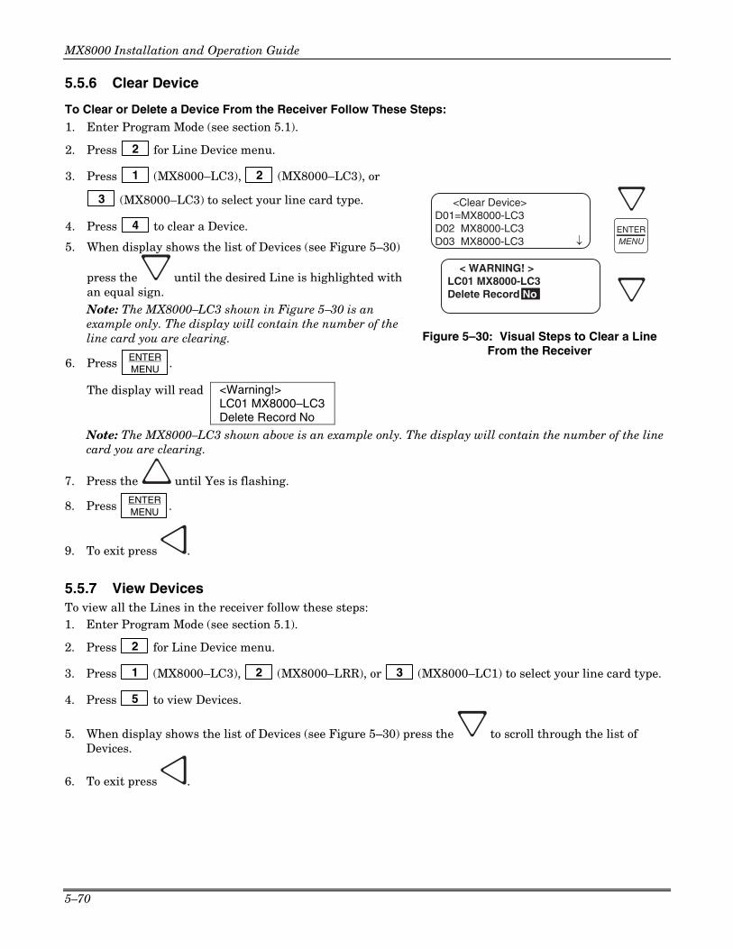
MX8000 Installation and Operation Guide
5–70
5.5.6 Clear Device
To Clear or Delete a Device From the Receiver Follow These Steps: 1. Enter Program Mode (see section 5.1).
2. Press 2 for Line Device menu.
3. Press 1 (MX8000–LC3), 2 (MX8000–LC3), or
3 (MX8000–LC3) to select your line card type.
4. Press 4 to clear a Device.
5. When display shows the list of Devices (see Figure 5–30)
press the until the desired Line is highlighted with an equal sign.
Note: The MX8000–LC3 shown in Figure 5–30 is an example only. The display will contain the number of the line card you are clearing.
6. Press ENTER MENU .
The display will read <Warning!> LC01 MX8000–LC3Delete Record No
< WARNING! >LC01 MX8000-LC3
<Clear Device>D01=MX8000-LC3D02 MX8000-LC3D03 MX8000-LC3 ¯
Delete Record No
ENTERMENU
Figure 5–30: Visual Steps to Clear a Line From the Receiver
Note: The MX8000–LC3 shown above is an example only. The display will contain the number of the line card you are clearing.
7. Press the until Yes is flashing.
8. Press ENTER MENU .
9. To exit press .
5.5.7 View Devices To view all the Lines in the receiver follow these steps: 1. Enter Program Mode (see section 5.1).
2. Press 2 for Line Device menu.
3. Press 1 (MX8000–LC3), 2 (MX8000–LRR), or 3 (MX8000–LC1) to select your line card type.
4. Press 5 to view Devices.
5. When display shows the list of Devices (see Figure 5–30) press the to scroll through the list of Devices.
6. To exit press .

Section 5 – Programming
5–71
5.6 User List
User List is used to program and store the information on the various installers and operators who will operate and maintain the receiver. Through this program menu item you can add, edit or clear (delete) an operator/installer (up to 40 users). The user is identified by name, and then assigned a PIN (personal identification number) and a profile. Table 5–17 lists the available choices under User List and provides a matrix of choices.
<User List>1=Add User2 Edit User3 Clear User
<Program Menu>3=User List< Exit Menu
¯
3
Figure 5–31: User List Menu Items
Table 5–17: User List Menu Items and Steps
Choice Step 1 Step 2 Step 3 Comments
Add User Enter user name: 1. Use the up or down arrow to
move through characters. 2. Press the right arrow to move to
next character slot. 3. Press enter key to move to next
step.
Enter PIN code: 4 digits minimum 9 digits maximum
Choose profile level: Operator or Installer
Add user is used to add a new user to the system and enter the user’s PIN and profile information.
Edit User When “Choose User” list appears: 1. Press the down arrow key until
the desired user is highlighted with the equal sign.
2. Press enter to move to next step.
Repeat Steps 1-3 under Add User.
Edit user is used to change an existing users profile.
Clear User When “Choose User” list appears: 1. Press the down arrow key until
the desired user is highlighted with the equal sign.
2. Press enter to move to clear user from profile list.
Clear user is used to delete a user from the receiver’s memory.
5.6.1 Adding a User Use the following steps to add a user to the system: 1. Log on to the receiver. (See Section 4.4.4 for log on procedure.)
2. Press ENTER MENU button.
3. Press 7 for program menu.
The display will briefly display Initializing Please wait . . .
4. Press 3 to choose User List.
5. Press 1 to add a user.
The user number to be programmed will appear in the display for one second. This user number will always be the lowest available user number.
6. Press the or arrow buttons to move through the available characters.

MX8000 Installation and Operation Guide
5–72
Table 5–18: Available Characters
Characters Comments
Space, 0-9, :, -, _, ., ,, &, *, # The word “Space” indicates that a physical space would be inserted if this character were chosen.
A-Z Upper case alphabetical characters
a-z Lower case alphabetical characters
There are 16 characters available for each user name. Note: If no characters are entered in the name field, the user name will default to “User #XX”. XX = the number location of the user being programmed. For example, if user 12 location is being programmed and no name characters are entered in the name field, then that user will be named User #12. When the desired character is flashing in the display:
7. Press the right arrow key. 8. Repeat steps 6 and 7 until the user’s name is complete.
9. Press ENTER MENU .
10. Enter the desired PIN code for the user. A minimum of 4 characters and a maximum of 9 characters.
11. Press ENTER MENU .
The display will flash Operator.
12. Press the or arrow buttons to toggle between Installer and Operator.
13. When the desired profile level is flashing press ENTER MENU .
5.6.2 Editing a User Use the following steps to edit an existing user:
1. Log on to the receiver. (See Section 4.4.4 for log on procedure.)
2. Press ENTER MENU button.
3. Press 7 for program menu.
The display will briefly display Initializing Please wait . . .
4. Press 3 to choose user list.
5. Press 2 to edit a user.
A list of all the users will appear starting with the lowest user number.
6. Press the or arrow buttons to move through the user list.
7. When the equal sign highlights the user you wish to edit press ENTER MENU .
8. If you do not want the user name changed, press ENTER MENU .
Or

Section 5 – Programming
5–73
To change the user name, press the or arrow buttons to move through the available characters. (See Table 5–18 for list of available characters.) When the name change is complete press
ENTER MENU .
9. If you do not want the PIN code changed, press ENTER MENU .
Or
To change the PIN code, enter the desired code (4 to 9 digits in length) then press ENTER MENU .
The display will flash the current profile level.
10. Press the or arrow buttons to toggle between Installer and Operator.
11. When the desired profile level is flashing press ENTER MENU .
5.6.3 Clearing a User Out of the Receiver Use the following steps to clear or delete a user from the system: 1. Log on to the receiver. (See Section 4.4.4 for log on procedure.)
2. Press ENTER MENU button.
3. Press 7 for program menu.
The display will briefly display Initializing Please wait . . .
4. Press 3 to choose user list.
5. Press 3 to clear (delete) a user.
A list of all the users will appear starting with the lowest user number.
6. Press the or arrow buttons to move through the user list.
7. When the equal sign highlights the user you wish to clear press ENTER MENU .
The display shows < WARNING ! > Delete Record No
8. Press the or arrow button to toggle the flashing display to Yes.
9. Press ENTER MENU .

MX8000 Installation and Operation Guide
5–74

6–1
Section 6 Compatible Reporting Formats
This section lists all the reporting formats that are compatible with the MX8000 receiver.
Table 6–1 shows the formats that the MX8000 receiver can decode and handshake frequency format group that accommodates that format (see Section 5.4.6 for line card programming). Each line card can decode every format listed below; however, a line card can be programmed to prioritize the handshake order in which that line card will communicate.
6.1 Formats By Communication Group.
Table 6–1 shows which formats fit under the general communication groups and the corresponding handshake frequency.
Table 6–1: Formats compatible with the MX8000
Communication Group
Format Name Description Handshake Format Group
SK 4+2 Sends a 4-digit account and a 2-digit alarm code up to four rounds.
1400 Hz
Sescoa 3+1/Franklin 3+1 Sends a 3-digit account and a 1-digit alarm code up to four rounds in a tone burst format. Each digit can be programmed from (0-9). Because there is no standard, this format reports in codes only.
2300 Hz
Radionics 3+1 Checksum Sends a 3-digit account and a 1-digit alarm code and a checksum.
1400 or 2300 Hz
SK 3+1/3+1 Extended Sends a 3-digit account and a 1-digit alarm code up to four rounds (10-40PPS). Each block of data (2 rounds). If a second block of data is sent, it will contain the extended information. The account number cannot have repetitive digits (333, 888, etc.).
1400 or 2300 Hz
4+1/4+1 Extended Sends a 4-digit account code and a 1-digit alarm code up to four rounds in a pulse format (10-40PPS).
4/1 1400 or 4/1 2300 Hz
Tone Burst
Pulse 4+2 Sends a 4-digit account code and a 2-digit alarm code.
1400 or 2300 Hz
ADEMCO Contact ID®, ADEMCO Contact ID10
Dual Tone Multiple Frequency. The data is decoded into English account information.
1400_2300 Hz
ADEMCO High Speed Sends a 4-digit account code and a 2-digit alarm code up to 9 events per call.
Acron TouchTone Sends a 4-digit account code and a 1-digit alarm code. Will send a maximum of 8 events per call.
ADEMCO Express Sends a 4-digit account code and a 2-digit alarm code with a checksum.
DTMF 4+2 Sends a 4-digit account code and a 2-digit alarm code with a checksum.
FBII 4+3+1 Sends a 4-digit account code, a 3-digit zone code and a 1-digit event code.
1400 or 2300 Hz
DTMF
Westec Sends a 4-digit account code, a 3-digit Dealer code followed by the event code.
Westec
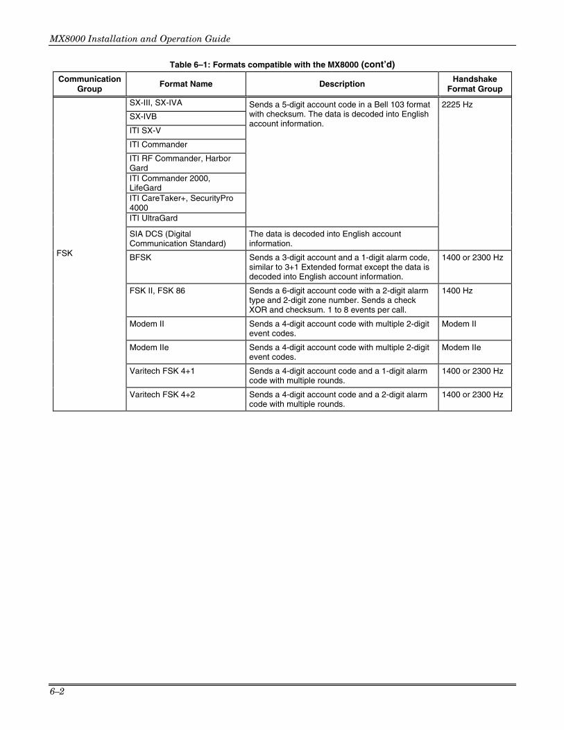
MX8000 Installation and Operation Guide
6–2
Table 6–1: Formats compatible with the MX8000 (cont’d)
Communication Group
Format Name Description Handshake Format Group
SX-III, SX-IVA 2225 Hz SX-IVB
ITI SX-V
ITI Commander
ITI RF Commander, Harbor Gard
ITI Commander 2000, LifeGard
ITI CareTaker+, SecurityPro 4000
ITI UltraGard
Sends a 5-digit account code in a Bell 103 format with checksum. The data is decoded into English account information.
SIA DCS (Digital Communication Standard)
The data is decoded into English account information.
BFSK Sends a 3-digit account and a 1-digit alarm code, similar to 3+1 Extended format except the data is decoded into English account information.
1400 or 2300 Hz
FSK II, FSK 86 Sends a 6-digit account code with a 2-digit alarm type and 2-digit zone number. Sends a check XOR and checksum. 1 to 8 events per call.
1400 Hz
Modem II Sends a 4-digit account code with multiple 2-digit event codes.
Modem II
Modem IIe Sends a 4-digit account code with multiple 2-digit event codes.
Modem IIe
Varitech FSK 4+1 Sends a 4-digit account code and a 1-digit alarm code with multiple rounds.
1400 or 2300 Hz
FSK
Varitech FSK 4+2 Sends a 4-digit account code and a 2-digit alarm code with multiple rounds.
1400 or 2300 Hz

Section 5 – Programming
6–3
6.2 Format Numbers Used In Printer Output
In a printed report the format used by a calling panel is listed as a number, that number represents a particular format. Table 6–2 lists these numbers along with the corresponding format.
Table 6–2: Formats By Report Number
Format Number Format Type
Format Number Format Type
4 SIA DCS 9 ITI
10 ITI SX-IVA 11 ITI PinPoint 12 ITI RF Commander
55
ADEMCO High Speed (SIA D1) output as SIA events when using the ADEMCO 8000, SK9000 or ITI Automation Protocol. ADEMCO High Speed output as raw data (ADEMCO format) when using the 685, CAPS, or CP220 Automation Protocol.
13 ITI Pro 1 or ITI Ultragard 14 ITI CareTaker + 15 ITI SX-V 16 ITI Commander 2000 17 ITI HarborGuard 18 ITI Reserved or ITI Simon
56
ADEMCO High Speed with checksum (SIA D1) output as SIA events when using the ADEMCO 8000, SK9000 or ITI Automation Protocol. ADEMCO High Speed with checksum output as raw data (ADEMCO format) when using the 685, CAPS, or CP220 Automation Protocol.
19 ITI Vector 57 ADEMCO DTMF 4/2 with checksum 20 ITI Hardwire Commander 58 ADEMCO DTMF 4/1 with checksum 21 ITI SX-V Special 59 Acron TouchTone 4 digit account. 22 ITI Marsden 60 BFSK 23 ITI Network Sec 61 Silent Knight FSK0/FSK80 24 ITI Nutone 62 Silent Knight FSK1/FSK81 25 ITI SX-IVB 63 Silent Knight FSK2/FSK86 30 Pulse Tone 3/1 31 Sescoa Franklin 3/1
64 FBII 4/3/1 with checksum or FBII 4/1/2/1 with
checksum 32 ADEMCO/Silent Knight 3/1 65 FBII 4/3/1 or FBII 4/1/2/1 33 Extended 3/1 70 Westec 871 35 Pulse tone 4/1 71 Westec W970 36 Sescoa Franklin 4/1 72 Westec W1000, W2000, W3000 37 ADEMCO/Silent Knight 4/1 73 Westec 45K 38 Extended 4/1 74 Modem II 40 Pulse Tone 4/2 75 Modem IIe 41 ADEMCO/Silent Knight 4/2 80 Pulse 32 43 Extended 4/2 81 Pulse 32 CS 46 Radionics 3/1 82 Pulse 41 CS 47 Radionics 3/1 with Checksum 83 ADEMCO Contact ID® 10-digit Account 48 Radionics 4/2 with Checksum 100 ITI Simon U 49 Sescoa Superspeed 101 Varitech FSK 4/1 50 Contact ID 102 Varitech FSK 4/2 51 ADEMCO TouchTone 52 Acron TouchTone 53 Westec TouchTone
103 Ademco High Speed output in high speed raw data (ADEMCO format) when using ADEMCO 8000, SK9000 or ITI Automation Protocol
54 ADEMCO Express
104 Ademco High Speed with checksum output in high speed raw data (ADEMCO format) when using ADEMCO 8000, SK9000 or ITI Automation Protocol
!WARNING!
• If you are receiving Contact ID®10 format on your MX8000 receiver you must use ADEMCO 8000 automation protocol.
• If you are receiving Contact ID® format on your MX8000 receiver you may use any automation protocol except the SK9000 automation protocol. The SK9000 automation protocol does not support Contact ID reporting format.

MX8000 Installation and Operation Guide
6–4
Important!
Due to the increasing number of formats a single line can accept and the wide variety of manufacturer’s specifications for handshake/acknowledgement tones required for their digital dialers to communicate, we strongly recommend observing the following rules for handshake tone order.
1. Some SIA DCS communicators respond to the 2300Hz handshake. Always place the 2225Hz handshake tone first for line cards accepting SIA DCS format.
2. Some Contact ID communicators respond to the 1400Hz handshake followed by the 2300Hz handshake instead of the dual tone 1400-2300Hz handshake (NAPCO Gemini communicators have been known to do this). Line cards accepting Contact ID should not have the 1400Hz followed by the 2300Hz before the dual tone 1400-2300Hz handshake.
3. SIA DCS communicators will respond to the Modem II and IIe handshakes. If a line card is to accept both SIA DCS and Modem II or IIe, the 2225Hz handshake must come before the Modem II and Modem IIe handshakes.
4. Some Westec panels will respond to the Modem II handshake. If a line card is to accept both Westec and Modem II formats, the Westec handshake must come before the Modem II handshake.
5. Some of ITI panels don't respond to the default 2225Hz handshake. They need a lot longer handshake duration than what we have in the MX8000 receiver. You don't want to change the default 2225Hz handshake (1st handshake group) because it's optimized for SIA panels. What you should do is to program the 2nd 2225Hz handshake group with a long handshake duration (say 2550 ms). This way, a SIA panel responds to the 1st 2225Hz handshake and ITI panels respond to the 2nd 2225Hz handshake.
6. 4/1 pulse format and 3/1 with check sum pulse format look exactly alike to the receiver. Both respond to the 1400Hz or 2300Hz handshake and both contain 5 pulses. You cannot send both signals to the same line card. To process data correctly, you must specify in the line card handshake option which format you are expecting to receive. To receive 4/1 pulse format, you must program one of the six handshake groups of the line card to be 4/1 1400Hz and/or 4/1 2300Hz (This is the default setting). If you want to handle 3/1 with check sum, program the line card with 1400Hz and/or 2300Hz. If both 2300Hz and 4/1 2300Hz are programmed in a line card, 4/1 is assumed regardless of what order you program handshake groups. If your customer must handle both 4/1 and 3/1 with check sum formats, he or she must send the signals to separate line cards.

7–1
Section 7 Troubleshooting
This section contains a list of possible error messages and a troubleshooting process for each.
7.1 Error Messages
Table 7–1 lists the error messages that are displayed on the VFD of the receiver as well as the message sent to the printer. There are two types of error messages that are displayed and printed, line card communication errors, and system event errors. Line card communication errors relate specifically to how the receiver communicated to an incoming call. System event errors relate specifically to the system and the performance of its peripheral devices such as the automation software, printers, etc. In Table 7–1, heading “LC Error” indicates that the error message was a line card communication error and “SYS Error” indicates any system event related error messages.
Table 7–1: Error Messages
LC Error
Sys Error
VFD Messages Printer Message Description What to Do
✔ No Data Received
No Data Received On an incoming call no data was sent to the receiver after the receiver gave its handshake tones.
Usually a wrong number.
✔ 0 Length Block 0 Length Blk One of the message blocks received contained no data.
Possibly a call with caller ID information but no data from a control panel.
✔ No Ack No Ack Receiver was unable to acknowledge the call.
Check the line card setup and retest the panel.
✔ Time Out Time Out The incoming call timed out and the phone line was released.
✔ Corrupted Data Corrupted Data Bad or corrupted data was sent to the receiver.
1. Retest Panel. 2. Replace panel. 3. Replace line card.
✔ Illegal Specifier Illegal Specifier An error occurred in the look-up table for this call message.
Call Technical Support.
✔ Undefined Event
Undefined Event The panel communicating to the receiver sent an event code that the receiver does not recognize.
✔ Unsupported Event
Unsupported Event The panel communicating to the receiver sent an event code that the receiver recognized but does not support.
✔ Unsupported Format
Unsupported Fmt The calling panel communicated in a format not supported by the receiver.
Program the panel to a different reporting format.
✔ Communication Error
Communication Error, Panel Requested Re-send
There was a communication error between the panel and the receiver and the receiver asked the panel to re-send the message.
If it continues test the panel.
✔ Possible Incomplete
Possible Incomplete Call
The receiver missed information in the call sequence.
Retest the panel.
✔ System Power Up
System Power Up Indicated that the receiver powered up. Check the connection of that device on the SBUS. If connection OK replace SBUS device (line cards and touchpads).

MX8000 Installation and Operation Guide
7–2
Table 7–1: Error Messages (cont’d)
LC Error
Sys Error
VFD Messages Printer Message Description What to Do
✔ Expander Trouble
Expander Trouble Trouble with a device connected to the SBUS.
✔ Expander Trbl Rst
Expander Trouble Restore
The trouble condition of a SBUS device was corrected.
✔ AC Trouble AC Trouble AC power failure. Check AC outlet and AC power cord.
✔ AC Trouble Rst AC Trouble Restore AC power was restored. Restores at 12VDC after a low battery condition.
✔ Battery Low Restore
Battery Low Restore
The backup battery power supply trouble has been corrected.
✔ Battery Low Battery Low The backup battery is checked continually every second. This message would be displayed if the backup battery were set to “Battery Bkp”. See Section 5.4.4. Indicates a low battery when the voltage drops to 10.2 VDC or lower.
Check battery cables. If they are OK replace backup battery.
✔ Local Program Begin
Local Program Begin User #
This message indicates the time a system “installer” entered program mode.
✔ Local Program End
Local Program End User #
This message indicates the time a system “installer” exited program mode.
✔ Local Program Fail
Local Program Fail User #
The receiver will stay in program mode for 15 minutes without any activity, then it will time out and go back to normal mode. This message indicates that an installer entered programming and did not exit programming before it timed out.
✔ Listen-in End Listen-in End A listen-in session completed
✔ Listen-in Begin Listen-in Begin A listen-in session started.
✔ System Date Changed
System Date Changed User #
An installer changed the system date.
✔ System Time Changed
System Time Changed User #
An installer changed the system time.
✔ Msg Queue Full Message Queue Full
Messages can be sent to automation computer, a printer or can be manually acknowledged. If one or more of these devices does not respond to messages being sent or manually acknowledged, the message queue will fill up. When the message queue is full the receiver will no longer accept incoming calls.
Verify that messages are acknowledged to any printers, automation software, and while in manual mode.
✔ Msg Queue Full restore
Message Queue Full restore
Indicates that the message queue full error has been corrected.
✔ Main Computer Trbl
Main Computer Trouble
A communication problem exists between the automation software and the receiver.
Check cable connections. Verify that the port is configured properly.
✔ Main Computer Rst
Main Computer Restore
The communication error between the receiver and the automation software has been corrected.

Section 7 – Troubleshooting
7–3
Table 7–1: Error Messages (cont’d)
LC Error
Sys Error
VFD Messages Printer Message Description What to Do
✔ Bkup Computer Trbl
Bkup Computer Trouble
A communication problem exists between the backup automation software and the receiver.
Check cable connections. Verify that the port is configured properly.
✔ Bkup Computer Rst
Bkup Computer Restore
The communication error between the receiver and the backup automation software has been corrected.
✔ Main Prn Off Trbl
Main Printer Off Line
The port programmed as the primary printer port is off line.
Check cable connections. Verify that the port is configured properly. Check power to printer.
✔ Main Prn Paper Out
Main Printer Paper Out
The port programmed as the primary printer port is out of paper.
Replace paper in printer.
✔ Main Prn Restore
Main Printer Restore
The error on the primary printer has been corrected.
✔ Bkup Prn Off Trbl
Bkup Printer Off Line
The port programmed as the backup printer port is off line.
Check cable connections. Verify that the port is configured properly. Check power to printer.
✔ Bkup Prn Paper Out
Bkup Printer Paper Out
The port programmed as the backup printer port is out of paper.
Replace paper in printer.
✔ Bkup Prn Restore
Bkup Printer Restore
The error on the backup printer has been corrected.
✔ DC Input Low Rst
DC Input Low Restore
The backup DC power supply trouble has been corrected.
Restores at 12VDC after a low battery condition.
✔ DC Input Low DC Input Low The backup battery is checked continually every second. This message would be displayed if the backup battery setting were set to “DC Bkp”. See Section 5.4.4. Indicates a low when the voltage drops to 10.2 VDC or lower.
Check the connection to the DC power supply. Verify the output from DC power supply.
✔ Msg Que > Warning
Message Queue Warning
When the message queue reaches the programmed level mark, this message is given as a pre-warning to “Message Queue Full”. See Section 5.4.5.1 to program the % level at which the receiver will indicate the warning.
Verify that messages are acknowledged to any printers, automation software, and while in manual mode.
✔ Msg Que < Warning
Message Queue Warning Restore
This message is given when the message queue drops below the programmed level after a message queue warning indication has displayed. See Section 5.4.5.2 to program the % level.
✔ LC Run in ROM Line Card Running ROM Code
The line card is not running the application code.
Replace the line card.
✔ Line Fault Line Fault The phone line voltage has dropped below the threshold voltage as programmed. (See Section 5.5.2.3.)
Check phone line outlet and phone cord.

MX8000 Installation and Operation Guide
7–4
Table 7–1: Error Messages (cont’d)
LC Error
Sys Error
VFD Messages Printer Message Description What to Do
✔ Line Fault Restore
Line Fault Restore Phone line voltage has been restored to normal parameters.
✔ LinePort Deleted
LinePort Record Deleted
A line card has been deleted.
✔ LinePort Added LinePort Record Added
A line card has been added.
✔ User Log In User Log In: User # A user has logged on to the receiver.
✔ User Log Out User Log Out: User #
A user has logged off of the receiver.
7.2 Unrecognized Reports
The MX8000 provides an output to the printer when a report is received in an unrecognized reporting format. This may happen in cases where the automation protocol selected does not match the reporting format set for a client. Examples of a good report and unrecognized report are provided below:
Good Report
In the example below, a Contact ID report was received and the MX8000 is set for ADEMCO 685 protocol.
[New] Opening-Cancel ID# 304 Group# 00
[New] Closing-Report ID# 004 Group# 00
[New] Opening-Report ID# 004 Group# 00
Unrecognized Report
In the example below, a Contact ID report was received and the MX8000 is set for SK9000 protocol which does not support Contact ID.
05/14/2002 11:00:51AM
Device #: 1-2 Format #: 0 Reference #: 119
No Data Received
7.3 Troubleshooting Process
Before you call Technical Support you may be able to solve the problem yourself by following these procedures. 1. Verify that a problem exists. 2. Check Fault Status.
This can be done by pressing the LOG STATUS . If the system fault LED is on, the display will read:
#01-InstallerLog Out[]<Press ¯ for status>
Press the down arrow to view fault messages.
3. Check the manual for suggestions or solutions. 4. Check connections. 5. Isolate the problem. Remove other devices that may be interfering. 6. Try swapping devices to isolate the problem.
7. Try to replace the problematic device. 8. Document the failures and the steps used to resolve them.

Section 7 – Troubleshooting
7–5
7.3.1 Removing the CPU, PS, User Interface Assembly Once Technical Support has determined that a problem exists with either the CPU, Power Supply, or the User Interface, use the following procedure to remove the assembly and return it to Honeywell for repair. 1. Disconnect AC power Cable.
2. Disconnect the backup battery. (See Figure 3–14.)
3. Remove the front plate by unscrewing the front plate retaining screws. (See Figure 3–1 for locations of front plate retaining screws.)
4. On the back of the receiver remove the four screws that hold the CPU, PS, User Interface Assembly to the chassis. (See Figure 7–1 for screw locations.)
ScrewLocations
COM 1
PARALLEL
100 VA
120 VAC ± 10%240 VAC ± 10%
50-60 Hz
WARNING!HIGH VOLTAGE PRESENT
DISCONNECT AC LINE ANDALL OTHER CONNECTORS
PROIR TO SERVICING
FUSE2.5A
SLOW BLOWREPLACE ONLY
WITH A FUSEOF SAME TYPE
UNUSED
RLY NO
RLY COM
BATT-
BATT+
RLY NC
COM 2
RELAY RATING2.5A 48VAC/VDC
Figure 7–1: User CPU, PS, User Interface Assembly retaining Screw Locations
5. From the front of the receiver, pull the CPU, PS, User Interface Assembly out of the receiver chassis.
7.3.2 Replacing the CPU, PS, User Interface Assembly 1. From the front of the receiver, slide the replacement CPU, PS, User Interface Assembly back into the
receiver chassis. 2. On the back of the receiver, replace the four screws that hold the CPU, PS, User Interface Assembly in
place. (See Figure 7–1.) 3. Reconnect the AC power cable.
Note: Make sure to plug the AC power cable into a grounded outlet. (See Section 3.11.2 for procedure on how to verify earth ground.)
4. Reconnect the back-up battery. (See Figure 3–14.)
5. Replace the front plate by screwing in the front plate retaining screws. (See Figure 3–1.)
7.4 Safe Mode
Safe mode can be used to reset User #01 access code back to default of MX8000 regardless of its present setting. For Example, if the code for the installer (User #01) is lost and additional programming is required the receiver can be restarted in safe mode to return User #01 to an access code of 8000. Follow these steps to initiate Safe Mode and default User code #01: 1. Follow the steps in Section 4.6.7 to restart the receiver.
Note: All messages must be acknowledged before a system restart procedure can be performed. If all messages are not acknowledged, cycle the receiver’s power to restart the system. If the power is cycled all unacknowledged messages will be lost.
2. When the display Shows Model MX8000 ReceiverADEMCO

MX8000 Installation and Operation Guide
7–6
3. Press the ✶✶✶✶ button, then the LOG STATUS button.
The display will read Safe Mode Activated
4. Press ENTER MENU .
5. Enter the default Installer code or 8000.

8–1
Section 8 Automation Communication Formats
8.1 Introduction
The receiver supports several automation communication formats that are used to communicate with an automation computer. The supported formats are Silent Knight’s proprietary protocol. The ADEMCO protocol is described in Section 8.2.
!WARNING!
• If you are receiving Contact ID®10 format on your MX8000 receiver, your automation software must be compatible with 10-digit account numbers, you must not use SK9000, ITI Generic, or ITI Enhanced automation protocols, and you must not use the MX8000-LC1 Line Card.
• If you are receiving Contact ID® format on your MX8000 receiver you may use any automation protocol except the SK9000 automation protocol. The SK9000 automation protocol does not support Contact ID reporting format.
8.1.1 Conventions Observed In This Section This manual uses the term “automation computer” to refer to a computer that receives data from the MX8000 and interprets it through software that automates the central station. For the purposes of this manual, a “message” is any data the MX8000 is passing to an automation computer. We’ll reserve the term message for discussions of the string as a whole. The term “call from panel” will refer to the complete data stream from a panel to the MX8000. The term “event data” will refer to the actual data, (that is, alarms, troubles, and so on), that are part of a call from a panel. The term “system message” will refer to messages the MX8000 sends to an automation computer about its internal status.
Another convention of this manual is to use hexadecimal values to refer to data (rather than the ASCII characters that represent the values). Hexadecimal numbers will be represented with a $ symbol in front of them as in “$0A”.
8.2 MX8000 Automation Protocols
The automation protocols available in the MX8000 are listed in Table 8–1 with a protocol description and automation computer setting.
RECOMMENDATION
We recommend using the ADEMCO 8000 automation protocol to take full advantage of all the formats and features of the MX8000.
Table 8–1: Automation Protocol Listing
MX8000 Setting Description Automation Computer Setting ADEM 8000 ADEMCO 8000 Protocol Ademco 8000 or Silent Knight Expanded ADEM 685 ADEMCO 685 Protocol Ademco 685 CAPS ADEMCO Caps Protocol Ademco Caps FBII220 FBII CP-220 Protocol FBII CP220 SK9000 Silent Knight 9000 Emulation Silent Knight 9000 ITI Gen ITI Generic ITI Generic ITI Comp ITI Comp ITI Comp

MX8000 Installation and Operation Guide
8–2
8.3 Reporting Formats and Automation Protocol Support
Table 8–2 provides a listing of the reporting formats supported by each type of automation protocol in the MX8000.
Table 8–2: Reporting Formats and Automation Protocol Support
Automation Protocol Reporting Format ADEMCO
8000 ADEMCO 685
ADEMCO 685 CAPS
FBII CP220
SK9000 ITI Generic
ITI Enhanced
3/1, 3/1 Ext YES YES YES YES YES YES YES 3/1 Even Round YES YES YES YES YES YES YES 3/1 w/cksum YES YES YES YES YES YES YES 3/1 Ext w/cksum YES YES YES YES YES YES YES 3/2 YES YES YES YES YES YES YES 3/2 Even Round YES YES YES YES YES YES YES 3/2 w/cksum YES YES YES YES YES YES YES 4/1, 4/1 Ext YES YES YES YES YES YES YES 4/1 Even Round YES YES YES YES YES YES YES 4/1 w/cksum YES YES YES YES YES YES YES 4/1 Ext w/cksum YES YES YES YES YES YES YES 4/2 YES YES YES YES YES YES YES 4/2 Even Round YES YES YES YES YES YES YES
1400
/230
0 H
z P
uls
e
4/2 w/cksum YES YES YES YES YES YES YES Acron Touchtone w/ 3-digit account
YES YES YES YES YES YES YES
Acron Touchtone w/ 4-digit account
YES YES YES YES YES YES YES
ADEMCO 4/1 w/cksum YES YES YES YES YES YES YES ADEMCO 4/2 w/cksum YES YES YES YES YES YES YES ADEMCO High Speed YES YES YES YES YES YES YES ADEMCO High Speed w/cksum
YES YES YES YES YES YES YES
Contact ID YES YES YES YES NO YES YES Contact ID10 YES YES YES YES NO NO NO FBII 4/3/1 YES NO NO YES YES YES YES FBII 4/3/1 w/cksum FBII Superfast
YES NO NO YES YES YES YES
Westec 970 YES NO NO NO YES YES YES
DT
MF
Westec 1000/ 2000/3000
YES NO NO NO YES YES YES
BFSK YES YES YES YES YES YES YES FSK0/FSK 8 YES NO NO NO YES YES YES FSK1/FSK 81 YES NO NO NO YES YES YES FSK2/FSK 86 YES NO NO NO YES YES YES ITI CareTaker+, SecurityPro 4000
YES NO NO NO YES YES YES
ITI Commander YES NO NO NO YES YES YES ITI Commander 2000, LifeGard
YES NO NO NO YES YES YES
ITI RF Commander, Harbor Gard
YES NO NO NO YES YES YES
ITI SX-V YES NO NO NO YES YES YES ITI UltraGard YES NO NO NO YES YES YES Radionics Modem II YES NO NO NO YES YES YES Radionics Modem IIE YES NO NO NO YES YES YES SIA DCS YES NO NO NO YES YES YES SX-III, SX-IVA YES NO NO NO YES YES YES SX-IVB YES NO NO NO YES YES YES Varitech FSK 4/1 YES YES YES YES YES YES YES
FS
K
Varitech FSK 4/2 YES YES YES YES YES YES YES

Section 8 – Automation Communication Formats
8–3
8.4 ADEMCO 8000
Because of the additional features and program capabilities of the MX8000 receiver over its predecessor the 9000 receiver, it was necessary to develop a new automation protocol. ADEMCO 8000 protocol addresses these needs. The following sections describes the three different types of data blocks (system message, heart beat message, and call message) that the ADEMCO 8000 will send to the automation computer, and the components of these data blocks. Each of these types of data blocks is preceded with an AE header block. At the end of each message is an "End of message indicator" (<$0D> or carriage return) preceded by a Validation Byte (or V-Byte used for error-checking). See Section 8.4.5.
8.4.1 AE Header Block The header block consists of 18 bytes of data and precedes all of the data blocks. The following is an example of an AE header.
Example: <Identifier><Date><$22><Time><$22><Rec#><$22><Ref#><$22>
Table 8–3 describes the components of an AE header block.
Table 8–3: AE Header Block Components Description
Character Description Acceptable Values <Identifier> Message type identifier. $02 System Message
$03 Heart Beat Message $26 Call Message
<Date> Date information, consisting of six ASCII bytes. MMDDYY format where MM = Month, DD = Day, YY = Year.
<$22> Separator N/A <Time> Time information, consisting of six ASCII bytes HHMMSS format, where
HH = Hour, MM = Minutes, SS = Seconds.
<$22> Separator N/A <Rec#> Receiver ID number. 01-99 <$22> Separator N/A <Ref#> Reference number, consisting of four ASCII
bytes. 0001-9999 (0000 is reserved for link tests.)
<$22> Separator N/A
8.4.2 Call Message Block A call message is generated any time a control panel calls into the receiver. This type of report will be the most frequent message block received by the automation computer from the receiver. Embedded in this message are the account number, time/date stamp, specific event information, along with any other miscellaneous information such as, caller ID, listen-in, etc. The following is a generic example of a call message block: Example: <AE header><Fmt#><LC#><Panel Data><V-byte><$0D>
Table 8–4 describes the components of a call message block.
Table 8–4: Call Message Components and Description
Character Description Acceptable Values <AE header> AE header block of data. See Section 8.4.1. <Fmt#> Dialer format number containing three ASCII digits. See 8.4.2.1. <LC#> Line Card number containing two ASCII digits. 00-99 <Panel Data> Contains account number, time/date stamp, caller ID
information, listen-in, reason for call, zone number, etc. See 8.4.2.2.
<V-byte> Validation byte. See Section 8.4.5. <$0D> End of message indicator (carriage return). N/A

MX8000 Installation and Operation Guide
8–4
8.4.2.1 Dialer Format The ADEMCO 8000 format takes advantage of additional format numbers and outputs information with greater detail about the dialer format. Table 8–5 lists the dialer format code and indicates the type of dialer associated with that number.
Table 8–5: Dialer Format Types By Code
Code Dialer Type Code Dialer Type 004 SIA DCS 052 Acron TouchTone 009 ITI 053 Westec TouchTone 010 ITI SX-IVA 054 ADEMCO Express 011 ITI PinPoint 012 ITI RF Commander
055 ADEMCO High Speed (SIA D1) output as SIA events
013 ITI Pro 1 or ITI Ultragard 014 ITI CareTaker +
056 ADEMCO High Speed with checksum (SIA D1) output as SIA events
015 ITI SX-V 057 ADEMCO DTMF 4/2 with checksum 016 ITI Commander 2000 058 ADEMCO DTMF 4/1 with checksum 017 ITI HarborGuard 059 Acron TouchTone 4 digit account. 018 ITI Reserved or ITI Simon 060 BFSK 019 ITI Vector 061 Silent Knight FSK0/FSK80 020 ITI Hardwire Commander 062 Silent Knight FSK1/FSK81 021 ITI SX-V Special 063 Silent Knight FSK2/FSK86 022 ITI Marsden 023 ITI Network Sec
064 FBII 4/3/1 with checksum or FBII 4/1/2/1 with checksum
024 ITI Nutone 065 FBII 4/3/1 or FBII 4/1/2/1 025 ITI SX-IVB 070 Westec 871 030 Pulse Tone 3/1 071 Westec W970 031 Sescoa Franklin 3/1 072 Westec W1000, W2000, W3000 032 ADEMCO/Silent Knight 3/1 073 Westec 45K 033 Extended 3/1 074 Modem II 035 Pulse tone 4/1 075 Modem IIe 036 Sescoa Franklin 4/1 080 Pulse 32 037 ADEMCO/Silent Knight 4/1 081 Pulse 32 CS 038 Extended 4/1 082 Pulse 41 CS 040 Pulse Tone 4/2 083 ADEMCO Contact ID® 10-digit Account 041 ADEMCO/Silent Knight 4/2 100 ITI Simon U 043 Extended 4/2 101 Varitech FSK 4/1 046 Radionics 3/1 102 Varitech FSK 4/2 047 Radionics 3/1 with Checksum 048 Radionics 4/2 with Checksum
103 Ademco High Speed output in high speed raw data (ADEMCO format)
049 Sescoa Superspeed 050 Contact ID
104 Ademco High Speed with checksum output in high speed raw data (ADEMCO format)
051 ADEMCO TouchTone
8.4.2.2 Panel Data Panel data contains all the data that pertains to the control panel that dialed into the receiver, such as the account number, what kind of alarm, the zone number, caller ID information, etc. Each record contains an identifier byte followed by data. Table 8–6 lists the characters used as identifiers and a description of each.
Table 8–6: Panel Data Identifiers and Descriptions
Character Description Character Description $05 Account number field 11h Caller ID name
$23 Event field (Bad data sent as hex-ASCII dump). See Section 8.11
12h Caller ID phone number $2A Listen-in call indicator. See Section 8.4.2.3. 13h Caller ID, others $2C Long call indicator. See Section 8.4.2.4. $22 Event field (Good Data)

Section 8 – Automation Communication Formats
8–5
Note: Caller ID to Automation – When enabled, Caller ID information is output to the automation system only in the event that no alarm data is received from a security system control panel. Example: <$26><“051697”><$22><“081356”><$22><“01”><$22><“0001”><$22><“004”><“01”>
<12h><“1-800-328-0103”><11h><“ADEMCO”><$05><“123456”><$22><“BA01”> <$22><“DC2”><$22><“RP”><V-byteV-byte><$0D>
Table 8–7 describes what each component of the call message means.
Table 8–7: Call Message Components
Component Description
<$26> Call message indicator.
<“051697”> Date-May 16th, 1997
<$22> Separator
<“081356”> Time-8:13:56 am
<$22> Separator
<“01”> Receiver number-1.
<$22> Separator
<“0001”> Reference number-0001
<$22> Separator
<“004”> Expanded dialer format -SIA DCS
<“01”> Line Card number-01
<12h> Caller ID phone number indicator
<“1-800-328-0103”> Caller ID phone number
<11h> Caller ID name field indicator
<“ADEMCO”> Caller ID name
<$05> Account number field indicator
<“123456”> Account number-123456
<$22> Good data field indicator.
*<“BA01”> Call event code-Burglary alarm, Zone 01.
<$22> Good data field indicator.
*<“DC2”> Call event code-Access Closed, Door 2
<$22> Good data field indicator.
*<“RP”> Call event code-Automatic Test
<V-byte> Validation Byte (V-byte). See Section 8.4.5.
<$0D> End of message indicator
*Note: Refer to SIA publication “Digital Communication Standard, February 1995 Revision,” or later for message syntax.
8.4.2.3 Listen-in Indicator If message sent to the automation computer contains a <$2A> (Listen-In indicator) followed the 3-ASCII digits, the control panel calling is requesting the receiver put the phone line into listen-in mode.
The MX8000 receiver uses the following standards to identify a listen-in account:
• First, the receiver searches for an embedded listen-in event in the panel data, depending on whether or not the reporting format supports listen-in.
• Second, the receiver compares the account number to those stored in the “listen-in accounts” list. See Section 5.5.2.4.
• Third, the receiver scans the line card flash record to determine if the listen-in is enabled for the line card.
• Fourth, if the above standards have been satisfied, the receiver sends the automation computer the listen-in indicator.

MX8000 Installation and Operation Guide
8–6
The following is an example of a call message containing a listen-in indicator:
Example: <FMT#><LC#><$05><123456><BA01><$2A><“060”><V-byte><$0D>
Table 8–8 describes the components of a call message containing a listen-in indicator.
Table 8–8: Call Message With Listen-in Data
Character Description
<AE header> AE header block of data. See Section 8.4.1.
<FMT#> Dialer format number containing three ASCII digits. See 8.4.2.1.
<LC#> Line Card number containing two ASCII digits.
<$05> Panel Data. See 8.4.2.2.
<123456>
<BA01>
<$2A> Listen-in indicator.
<“060”> Listen-in time period in seconds. Three ASCII characters- 60 seconds.
<V-byte> Validation byte. See Section 8.4.5.
<$0D> End of message indicator.
Note: If the control panel calling does not include the listen-in period in the reporting message, the receiver uses the listen-in timeout programmed in the line card. See Section 5.5.2.4.
8.4.2.4 Long Call Indicator The maximum number of bytes the ADEMCO 8000 protocol can send to the automation computer in a single packet is 128. If a panel sends more than 128 bytes, the receiver will break the panel information data down into groups of 128 bytes or less. To alert the automation computer that this is being done, a long call indicator (<$2C>) will be added before the V-byte to indicate more data is to follow.
The entire data string in a long call contains the same values in the header block. The last data string of the long call will not contain a long call indicator prior to the V-byte.
The example below shows the long call data excluding the AE header and the panel data. ....<$2C><V-byte><$0D>
Note: Some panels are capable of transmitting multiple account information in a single call. The MX8000 receiver will treat a call with multiple accounts as multiple calls with a single account and will divide the call into multiple data blocks. However, to distinguish them from a call with a single account, each data block of a call with multiple accounts will contain the same reference number and a long call indicator with the exception of the last block of data.
8.4.2.5 Bad Data Field Indicator If the data received by the MX8000 is garbled or parts are missing the receiver will send a bad data indicator (<$23> used in the event block as a separator) before the block of corrupted data. A bad data block will contain a hex-ASCII dump of the data in ASCII form.
The example below shows a bad data field indicator excluding the AE header and some of the panel data.
Example: <$23><aaaaaaaa><$23><bbbbb><$05><“123456”><$22><“BA01”><V-byte><$0D>
Table 8–9 shows the character in the above example and gives a description for each.

Section 8 – Automation Communication Formats
8–7
Table 8–9: Bad Data Field Indicator Components
Character Description
<$23> Bad data indicator
<aaaaaaaa> Bad data ASCII hex data dump.
<$23> Bad data indicator
<bbbbb> Bad data ASCII hex data dump.
<$05> Account number field indicator
<“123456”> Account number.
<$22> Separator - Good data.
<“BA01”> Panel Data. See 8.4.2.2.
<V-byte> Validation Byte. See Section 8.4.5.
<$0D> End of message indicator.
8.4.3 System Message Block System messages originate from the receiver and are sent to the automation computer. The length of the message is dependent on its function of the message. All system messages are sent separately from one another and from other types of messages.
A typical system message looks like this: <AE header><System><V-byte><$0D>
Example: <$02><“051697”><$22><“124039”><$22><“02”><$22><“0001”><$22><70h><“01”><V-byte><$0D>
Table 8–10 lists the components of the system message block example and gives a description for each of them.
Table 8–10: System Message Components
Character Description
<$02> Message type identifier.
<“051697”> Date information, consisting of six ASCII bytes.
<$22> Separator
<“124039”> Time information, consisting of six ASCII bytes
<$22> Separator
<“02”> Receiver number
<$22> Separator
<“0001”> Reference number, consisting of four ASCII bytes.
<$22> Separator
<$70> System event - line card trouble. See 8.4.3.1 for list of system messages.
<“01”> Line Card number - 01.
<V-byte> Validation Byte (V-byte). See Section 8.4.5.
<$0D> End of message indicator.
8.4.3.1 System Messages Table 8–11 lists all the system messages that the receiver can send to the automation computer.
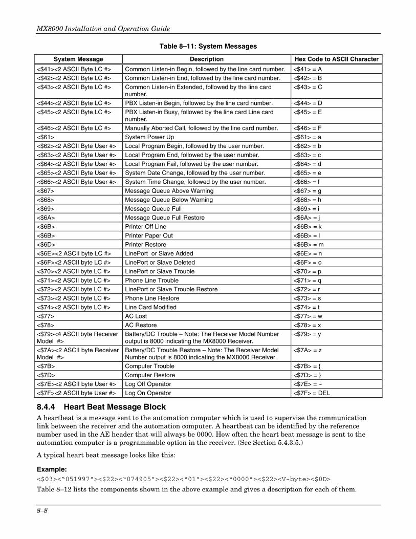
MX8000 Installation and Operation Guide
8–8
Table 8–11: System Messages
System Message Description Hex Code to ASCII Character
<$41><2 ASCII Byte LC #> Common Listen-in Begin, followed by the line card number. <$41> = A
<$42><2 ASCII Byte LC #> Common Listen-in End, followed by the line card number. <$42> = B
<$43><2 ASCII Byte LC #> Common Listen-in Extended, followed by the line card number.
<$43> = C
<$44><2 ASCII Byte LC #> PBX Listen-in Begin, followed by the line card number. <$44> = D
<$45><2 ASCII Byte LC #> PBX Listen-in Busy, followed by the line card Line card number.
<$45> = E
<$46><2 ASCII Byte LC #> Manually Aborted Call, followed by the line card number. <$46> = F
<$61> System Power Up <$61> = a
<$62><2 ASCII Byte User #> Local Program Begin, followed by the user number. <$62> = b
<$63><2 ASCII Byte User #> Local Program End, followed by the user number. <$63> = c
<$64><2 ASCII Byte User #> Local Program Fail, followed by the user number. <$64> = d
<$65><2 ASCII Byte User #> System Date Change, followed by the user number. <$65> = e
<$66><2 ASCII Byte User #> System Time Change, followed by the user number. <$66> = f
<$67> Message Queue Above Warning <$67> = g
<$68> Message Queue Below Warning <$68> = h
<$69> Message Queue Full <$69> = i
<$6A> Message Queue Full Restore <$6A> = j
<$6B> Printer Off Line <$6B> = k
<$6B> Printer Paper Out <$6B> = l
<$6D> Printer Restore <$6B> = m
<$6E><2 ASCII byte LC #> LinePort or Slave Added <$6E> = n
<$6F><2 ASCII byte LC #> LinePort or Slave Deleted <$6F> = o
<$70><2 ASCII byte LC #> LinePort or Slave Trouble <$70> = p
<$71><2 ASCII byte LC #> Phone Line Trouble <$71> = q
<$72><2 ASCII byte LC #> LinePort or Slave Trouble Restore <$72> = r
<$73><2 ASCII byte LC #> Phone Line Restore <$73> = s
<$74><2 ASCII byte LC #> Line Card Modified <$74> = t
<$77> AC Lost <$77> = w
<$78> AC Restore <$78> = x
<$79><4 ASCII byte Receiver Model #>
Battery/DC Trouble – Note: The Receiver Model Number output is 8000 indicating the MX8000 Receiver.
<$79> = y
<$7A><2 ASCII byte Receiver Model #>
Battery/DC Trouble Restore – Note: The Receiver Model Number output is 8000 indicating the MX8000 Receiver.
<$7A> = z
<$7B> Computer Trouble <$7B> = {
<$7D> Computer Restore <$7D> = }
<$7E><2 ASCII byte User #> Log Off Operator <$7E> = ~
<$7F><2 ASCII byte User #> Log On Operator <$7F> = DEL
8.4.4 Heart Beat Message Block A heartbeat is a message sent to the automation computer which is used to supervise the communication link between the receiver and the automation computer. A heartbeat can be identified by the reference number used in the AE header that will always be 0000. How often the heart beat message is sent to the automation computer is a programmable option in the receiver. (See Section 5.4.3.5.)
A typical heart beat message looks like this:
Example: <$03><“051997”><$22><“074905”><$22><“01”><$22><“0000”><$22><V-byte><$0D>
Table 8–12 lists the components shown in the above example and gives a description for each of them.

Section 8 – Automation Communication Formats
8–9
Table 8–12: Link Test Components
Component Description
<$03> Message type identifier.
<“051997”> Date information, consisting of six ASCII bytes.
<$22> Separator
<“074905”> Time information, consisting of six ASCII bytes
<$22> Separator
<“01”> Receiver number
<$22> Separator
<“0000”> Reference number, consisting of four ASCII bytes.
<$22> Separator
<V-byte> Validation Byte (V-byte). See Section 8.4.5.
<$0D> End of message indicator.
8.4.5 Validation Byte (V-Byte) A V-byte always precedes the end of message indicator and is the only error checking used by the ADEMCO 8000 communication format. The following equations are used to calculate the V-byte:
1. Add the 1st byte of the message to the 2nd byte. 2. Clear bit 7 of the result. 3. Set bit 6 of the result. 4. Add this result to the next byte of the message.
5. Repeat steps 2 through 4 until the last byte of the event data. (Up to and including the byte preceding the validation byte.) The range of the sum is from $40 to $7F.
8.4.6 ACKing and NACKing Data After the end of message byte (<$0D>) is sent by the receiver, the automation computer will respond with an ACK (<$06>) or NACK (<$15>). This response can be delayed between 1 byte time (depending on the baud rate) and the ACK timeout period. See Section 5.4.3.5 page 5–19. If the receiver doesn’t get a response within the ACK timeout period or receive a NACK from the automation computer, it will retransmit the data.
After two NACKs or two ACKs timeout, the receiver will generate a Computer Trouble message. When a computer trouble message is generated, then the receiver will continually send a heartbeat until it receives an ACK from the automation computer. When communication is restored, a Computer Trouble Restore message will be generated.
8.4.7 Commands Initiated by the Automation Computer Typically all communications are initiated by the receiver; however, there are several commands available to the automation computer to control or request information from the receiver. The automation computer may send these requests only when the receiver is not transmitting data to it. The following sub-sections show the message format that must be sent from the automation computer to the receiver in order that these command requests function properly. The receiver will respond to these requests from the automation computer with one of the following messages:

MX8000 Installation and Operation Guide
8–10
Table 8–13: Response Messages by the MX8000 Receiver
ASCII Hex Character
Character Name Description
$06 ACK The request is granted.
$15 NACK The request is unrecognized because of one of the following reasons: • Checksum error
• Invalid request code/format
$1B ESC (Escape) The request is refused because of one of the following: • Unauthorized access
• Invalid receiver/line card number
• Receiver/line card is busy
• Invalid PBX string • Account list full
• Account number not found in the account list
Table 8–14 lists which request can be made from the automation computer by request identifiers.
Table 8–14: Command Requests by Identifiers
Command Request Identifier
Description
$4A Log-on request
$4B Log-off request
$05 Hang up request
$04 Add a listen-in account. (This adds an account number to the listen-in account list.)
$03 Delete a listen-in account. (This deletes an account number from the listen-in account list.)
$4C Listen-in extend request.
$48 Listen-in end request.
$49 PBX string request.
$0D Link test request.
8.4.7.1 Remote Log-on/Log-off You must log-on to the receiver before you can change any system program options. Remote log-in and log-off commands can be sent from the automation computer to the receiver.
To Log-in: <$4A><Receiver ID><$22><User PIN><V-byte><$0D>
Table 8–15: Log-in Request Components
Component Description
<$4A> Command request identifier. See Table 8–14.
<Receiver ID> Receiver ID number. 1 or 2 ASCII digits.
<$22> Separator
<User PIN> The users PIN code.
<V-byte> Validation Byte (V-byte). See 8.4.5.
<$0D> End of message indicator.
To Log-off: <$4B><Receiver ID><$22><User PIN><V-byte><$0D>

Section 8 – Automation Communication Formats
8–11
Table 8–16: Log-off Request Components Component Description
<$4B> Command request identifier. See Table 8–14. <Receiver ID> Receiver ID number. 1 or 2 ASCII digits. <$22> Separator <User PIN> The user’s PIN code. <V-byte> Validation Byte (V-byte). See 8.4.5. <$0D> End of message indicator.
8.4.7.2 Force Hang-up Request This command is used to immediately hang up the phone line regardless of the state of the line card. To Force Hang-up: <$05><Receiver ID><$22><LC#><V-byte><$0D>
Table 8–17: Force Hang-Up Request Components Component Description
<$05> Command request identifier. See Table 8–14. <Receiver ID> Receiver ID number. 1 or 2 ASCII digits. <$22> Separator <LC#> The LinePort number. <V-byte> Validation Byte (V-byte). See 8.4.5. <$0D> End of message indicator.
8.4.7.3 Add or Delete a Listen-in Account If the account number of a control panel is in the listen-in account list, when that control panel calls in to the receiver, the receiver will perform a listen-in operation with that control panel. The maximum length of a listen-in account number is 8 characters and may include wild card characters (# and or *). Each line card can have up to 20 listen-in account strings. See also Section 5.5.2.4. Note: The listen-in account list applies to panels that do not send listen-in commands as a part of their message (Contact ID E606 or SIA LF and LE).
To Add a Listen-in Account: <$04><Receiver ID><$22><LC#><$22><Act#><V-byte><$0D>
Table 8–18: Add Listen-in Account Request Components Component Description
<$04> Command request identifier. See Table 8–14. <Receiver ID> Receiver ID number. 1 or 2 ASCII digits. <$22> Separator <LC#> The LinePort number. <$22> Separator <Act#> Account number to be added to the listen-in account list. <V-byte> Validation Byte (V-byte). See 8.4.5. <$0D> End of message indicator.
To Delete a Listen-in Account: <$03><Receiver ID><$22><LC#><$22><Act#><V-byte><$0D>
Table 8–19: Delete a Listen-in Account Request Components Component Description
<$03> Command request identifier. See Table 8–14. <Receiver ID> Receiver ID number. 1 or 2 ASCII digits. <$22> Separator <LC#> The LinePort number. <$22> Separator <Act#> Account number to be deleted from the listen-in account list. <V-byte> Validation Byte (V-byte). See 8.4.5. <$0D> End of message indicator.

MX8000 Installation and Operation Guide
8–12
8.4.7.4 Common Listen-in Extend/End Request During a listen-in operation if the call requires additional time you can extend the listen-in period by sending an extend request. At the end of a listen-in call you can end the session by sending an end request. Some control panels send a listen-in period included in the reported message to the receiver. If the listen-in period is not sent from the control panel, the programmed listen-in period will be used. See Section 5.5.2.4.
To Extend Listen-in: <$4C><Receiver ID><$22><LC#><V-byte><$0D>
Table 8–20: Extend Listen-in Period Request Components
Component Description
<$4C> Command request identifier. See Table 8–14.
<Receiver ID> Receiver ID number. 1 or 2 ASCII digits.
<$22> Separator
<LC#> The LinePort number.
<V-byte> Validation Byte (V-byte). See 8.4.5.
<$0D> End of message indicator.
To End a Listen-in Session: <$48><Receiver ID><$22><LC#><V-byte><$0D>
Table 8–21: End Listen-in Period Request Components
Component Description
<$48> Command request identifier. See Table 8–14.
<Receiver ID> Receiver ID number. 1 or 2 ASCII digits.
<$22> Separator
<LC#> The LinePort number.
<V-byte> Validation Byte (V-byte). See 8.4.5.
<$0D> End of message indicator.
8.4.7.5 PBX Listen-in String When PBX listen-in mode is selected (see Section 5.5.2.4), the receiver will transfer the call to the extension X string. The PBX string can also be programmed in to the receiver from the automation computer.
To Create or Edit PBX String: <$49><Receiver ID><$22><LC#><$22><PBX String><V-byte><$0D>
Table 8–22: Delete a Listen-in Account Request Components
Component Description
<$49> Command request identifier. See Table 8–14.
<Receiver ID> Receiver ID number. 1 or 2 ASCII digits.
<$22> Separator
<LC#> The LinePort number.
<$22> Separator
<PBX String> PBX string to transfer a call to a specified extension. See Table 5–13 for valid string characters.
<V-byte> Validation Byte (V-byte). See 8.4.5.
<$0D> End of message indicator.

Section 8 – Automation Communication Formats
8–13
8.4.7.6 Link Test Request The automation computer can send a link test request to the MX8000 receiver to test the communication link between the receiver and the automation computer. The automation computer simply sends a <$0D> and the MX8000 receiver will respond.
8.5 ADEMCO 685 Automation Protocol
8.5.1 Low Speed 3x1, 4x1, and 4x1 Express Automation Protocols When the MX8000 is operating in the ADEMCO 685 mode and receives a 3x1, 4x1, and 4x1 Express transmission, the output protocol to the computer is as shown in Figure 8–1. Note that when a 3x1 transmission is received, the account number will be padded to 4 characters by the addition of a leading 0 to the account number.
LFRG 1234 ECR
TERMINATOR (ASCII CARRIAGE RETURN - HEX 0D)EVENT CODESPACE (ASCII SPACE CHARACTER - HEX 20)
RECEIVER NUMBER
ACCOUNT NUMBER
GROUP NUMBER
HEADER (ASCII LINE FEED - HEX 0A)
SPACE (ASCII SPACE CHARACTER - HEX 20)
Figure 8–1: 685 3x1, 4x1, 4x1 Express Protocol
8.5.2 Low Speed 4x2 and 4x2 Express Automation Protocols When the MX8000 is operating in the ADEMCO 685 mode and receives a 4x2 or 4x2 Express transmission, the output protocol to the computer is as shown in Figure 8–2.
LFRG 1234 E ZCR
TERMINATOR (ASCII CARRIAGE RETURN - HEX 0D)EVENT CODE (SECOND DIGIT)SPACE (ASCII SPACE CHARACTER - HEX 20)
SPACE (ASCII SPACE CHARACTER - HEX 20)
EVENT CODE (FIRST DIGIT)
ACCOUNT NUMBER
GROUP NUMBER
SPACE (ASCII SPACE CHARACTER - HEX 20)
RECEIVER NUMBERHEADER (ASCII LINE FEED - HEX 0A)
Figure 8–2: 685 4x2 and 4x2 Express Protocol
8.5.3 ADEMCO High Speed Automation Protocols When the MX8000 is operating in the ADEMCO 685 mode and receives an ADEMCO High Speed transmission, the output protocol to the computer is as shown in Figure 8–3.

MX8000 Installation and Operation Guide
8–14
LFRG 1234 NNNN NNNN NCR
TERMINATOR (ASCII CARRIAGE RETURN - HEX 0D)CHANNEL REPORT CODE, CHANNEL 9SPACE (ASCII SPACE CHARACTER - HEX 20)
SPACE (ASCII SPACE CHARACTER - HEX 20)
CHANNEL REPORT CODE, CHANNELS 5-8
CHANNEL REPORT CODE, CHANNELS 1-4
ACCOUNT NUMBER
SPACE (ASCII SPACE CHARACTER - HEX 20)
SPACE (ASCII SPACE CHARACTER - HEX 20)GROUP NUMBERRECEIVER NUMBERHEADER (ASCII LINE FEED - HEX 0A)
Figure 8–3: 685 ADEMCO High Speed Protocol
8.5.4 685 Contact ID
When the MX8000 receives a Contact ID® (also referred to as Point ID – PID) transmission while operating in the 685 mode, the output protocol to the computer is as shown in Figure 8–4.
LFRG 1234 18 QXYZ GG FCCC CR
3 DECIMAL DIGITS REPRESENTING CONTACT OR USERDEFINES CCC. C = CONTACT, U = USER.
TERMINATOR (ASCII CARRIAGE RETURN - HEX 0D)SPACE (ASCII SPACE CHARACTER - HEX 20)
SPACE (ASCII SPACE CHARACTER - HEX 20)2 DIGIT GROUP NUMBERSPACE (ASCII SPACE CHARACTER - HEX 20)EVENT DEFINITION CODEEVENT CHARACTER WHERE E = EVENT, NEW ALARM/OPENING R = RESTORE/CLOSINGSPACE (ASCII SPACE CHARACTER - HEX 20)DEDICATED IDENTIFIER FOR CONTACT IDSPACE (ASCII SPACE CHARACTER - HEX 20)4 DECIMAL DIGIT ACCOUNT NUMBERSPACE (ASCII SPACE CHARACTER - HEX 20)RECEIVER GROUP NUMBER (0-9)RECEIVER NUMBER (0-9)HEADER (ASCII LINE FEED - HEX 0A)
Figure 8–4: 685 Contact ID Protocol
ADEMCO DTMF formats will not transmit a true TouchTone “0” therefore, all “A”s are converted to 0 (zero) prior to output. The code string contains spaces at the points shown in Figure 8–4. Contact ID Event Definition Codes are provided in Table 8–23.

Section 8 – Automation Communication Formats
8–15
Table 8–23: Contact ID Event Definition Codes
EVENT DATA TYPE ALARMS
Medical Alarms -100
100 Medical Zone 101 Personal Emergency Zone 102 Fail to report in Zone
Fire Alarms -110 110 Fire Zone 111 Smoke Zone 112 Combustion Zone 113 Water flow Zone 114 Heat Zone 115 Pull Station Zone 116 Duct Zone 117 Flame Zone 118 Near Alarm Zone 126 Hold-up suspicion print
Panic Alarms -120
120 Panic Zone 121 Duress User 122 Silent Zone 123 Audible Zone 124 Duress – Access granted Zone 125 Duress – Egress granted Zone 126 Hold-up suspicion print User
Burglar Alarms -130
130 Burglary Zone 131 Perimeter Zone 132 Interior Zone 133 24 Hour (Safe) Zone 134 Entry/Exit Zone 135 Day/night Zone 136 Outdoor Zone 137 Tamper Zone 138 Near alarm Zone 139 Intrusion Verifier Zone
General Alarm -140 Zone
140 General Alarm Zone 141 Polling loop open Zone 142 Polling loop short Zone 143 Expansion module failure Zone 144 Sensor tamper Zone 145 Expansion module tamper Zone 146 Silent Burglary Zone 147 Sensor Supervision Failure Zone
24 Hour Non-Burglary -150 and 160
150 24 Hour Non-Burglary Zone 151 Gas detected Zone 152 Refrigeration Zone 153 Loss of heat Zone 154 Water Leakage Zone 155 Foil Break Zone 156 Day Trouble Zone 157 Low bottled gas level Zone

MX8000 Installation and Operation Guide
8–16
Table 8–23: Contact ID Event Definition Codes (continued)
EVENT DATA TYPE 158 High temp Zone 159 Low temp Zone 161 Loss of air flow Zone 162 Carbon Monoxide detected Zone 163 Tank level Zone SUPERVISORY
Fire Supervisory -200 and 210
200 Fire Supervisory Zone 201 Low water pressure Zone 202 Low CO2 Zone 203 Gate valve sensor Zone 204 Low water level Zone 205 Pump activated Zone 206 Pump failure Zone TROUBLES
System Troubles -300 and 310
300 System Trouble Zone 301 AC Loss Zone 302 Low system battery Zone 303 RAM Checksum bad Zone 304 ROM checksum bad Zone 305 System reset Zone 306 Panel programming changed Zone 307 Self-test failure Zone 308 System shutdown Zone 309 Battery test failure Zone 310 Ground fault Zone 311 Battery Missing/Dead Zone 312 Power Supply Over current Zone 313 Engineer Reset User 314 Primary Power Supply Failure Zone
Sounder / Relay Troubles -320
320 Sounder/Relay Zone 321 Bell 1 Zone 322 Bell 2 Zone 323 Alarm relay Zone 324 Trouble relay Zone 325 Reversing relay Zone 326 Notification Appliance Ckt. # 3 Zone 327 Notification Appliance Ckt. #4 Zone
System Peripheral Trouble -330 and 340
330 System Peripheral trouble Zone 331 Polling loop open Zone 332 Polling loop short Zone 333 Expansion module failure Zone 334 Repeater failure Zone 335 Local printer out of paper Zone 336 Local printer failure Zone 337 Exp. Module DC Loss Zone 338 Exp. Module Low Batt. Zone 339 Exp. Module Reset Zone 341 Exp. Module Tamper Zone 342 Exp. Module AC Loss Zone 343 Exp. Module self-test fail Zone 344 RF Receiver Jam Detect Zone

Section 8 – Automation Communication Formats
8–17
Table 8–23: Contact ID Event Definition Codes (continued)
EVENT DATA TYPE Communication Troubles -350 and 360
350 Communication trouble Zone 351 Telco 1 fault Zone 352 Telco 2 fault Zone 353 Long Range Radio xmitter fault Zone 354 Failure to communicate event Zone 355 Loss of Radio supervision Zone 356 Loss of central polling Zone 357 Long Range Radio VSWR problem Zone
Protection Loop -370
370 Protection loop Zone 371 Protection loop open Zone 372 Protection loop short Zone 373 Fire trouble Zone 374 Exit error alarm (zone) Zone 375 Panic zone trouble Zone 376 Hold-up zone trouble Zone 377 Swinger Trouble Zone 378 Cross-zone Trouble Zone
Sensor Trouble -380
380 Sensor trouble Zone 381 Loss of supervision - RF Zone 382 Loss of supervision - RPM Zone 383 Sensor tamper Zone 384 RF low battery Zone 385 Smoke detector Hi sensitivity Zone 386 Smoke detector Low sensitivity Zone 387 Intrusion detector Hi sensitivity Zone 388 Intrusion detector Low sensitivity Zone 389 Sensor self-test failure Zone 391 Sensor Watch trouble Zone 392 Drift Compensation Error Zone 393 Maintenance Alert Zone OPEN/CLOSE/REMOTE ACCESS
Open/Close -400, 440, 450, 460 400 Open/Close User 401 O/C by user User 402 Group O/C User 403 Automatic O/C User 404 Late to O/C (Note: use 453, 454 instead) User 405 Deferred O/C (Obsolete- do not use) User 406 Cancel User 407 Remote arm/disarm User 408 Quick arm User 409 Keyswitch O/C User 441 Armed STAY User 442 Keyswitch Armed STAY User 450 Exception O/C User 451 Early O/C User 452 Late O/C User 453 Failed to Open User 454 Failed to Close User 455 Auto-arm Failed User 456 Partial Arm User 457 Exit Error (user) User 458 User on Premises User 459 Recent Close User 461 Wrong Code Entry Zone

MX8000 Installation and Operation Guide
8–18
Table 8–23: Contact ID Event Definition Codes (continued)
EVENT DATA TYPE 462 Legal Code Entry User 463 Re-arm after Alarm User 464 Auto-arm Time Extended User 465 Panic Alarm Reset Zone 466 Service On/Off Premises User
Remote Access -410 411 Callback request made User 412 Successful download/access User 413 Unsuccessful access User 414 System shutdown command received User 415 Dialer shutdown command received User 416 Successful Upload Zone
Access control -420, 430
421 Access denied User 422 Access report by user User 423 Forced Access Zone 424 Egress Denied User 425 Egress Granted User 426 Access Door propped open Zone 427 Access point Door Status Monitor trouble Zone 428 Access point Request To Exit trouble Zone 429 Access program mode entry User 430 Access program mode exit User 431 Access threat level change User 432 Access relay/trigger fail Zone 433 Access RTE shunt Zone 434 Access DSM shunt Zone 435 Second Person Access User 436 Irregular Access User BYPASSES / DISABLES
System Disables -500 and 510
501 Access reader disable Zone
Sounder / Relay Disables -520
520 Sounder/Relay Disable Zone 521 Bell 1 disable Zone 522 Bell 2 disable Zone 523 Alarm relay disable Zone 524 Trouble relay disable Zone 525 Reversing relay disable Zone 526 Notification Appliance Ckt. # 3 disable Zone 527 Notification Appliance Ckt. # 4 disable Zone
System Peripheral Disables -530 and 540
531 Module Added Zone 532 Module Removed Zone
Communication Disables -550 and 560
551 Dialer disabled Zone 552 Radio transmitter disabled Zone 553 Remote Upload/Download disabled Zone
Bypasses -570
570 Zone/Sensor bypass Zone 571 Fire bypass Zone 572 24 Hour zone bypass Zone

Section 8 – Automation Communication Formats
8–19
Table 8–23: Contact ID Event Definition Codes (continued)
EVENT DATA TYPE 573 Burg. Bypass Zone 574 Group bypass User 575 Swinger bypass Zone 576 Access zone shunt Zone 577 Access point bypass Zone 578 Vault Bypass Zone 579 Vent Zone Bypass Zone
TEST / MISC.
Test/Misc. -600, 610
601 Manual trigger test report Zone 602 Periodic test report Zone 603 Periodic RF transmission Zone 604 Fire test User 605 Status report to follow Zone 606 Listen-in to follow Zone 607 Walk test mode User 608 Periodic test - System Trouble Present Zone 609 Video Xmitter active Zone 611 Point tested OK Zone 612 Point not tested Zone 613 Intrusion Zone Walk Tested Zone 614 Fire Zone Walk Tested Zone 615 Panic Zone Walk Tested Zone 616 Service Request Zone
Event Log -620
621 Event Log reset Zone 622 Event Log 50% full Zone 623 Event Log 90% full Zone 624 Event Log overflow Zone 625 Time/Date reset User 626 Time/Date inaccurate Zone 627 Program mode entry Zone 628 Program mode exit Zone 629 32 Hour Event log marker Zone
Scheduling -630
630 Schedule change Zone 631 Exception schedule change Zone 632 Access schedule change Zone
Personnel Monitoring -640
641 Senior Watch Trouble Zone 642 Latch-key Supervision User
Misc. -650, 700, 900
651 Reserved for ADEMCO Use Zone 652 Reserved for ADEMCO Use User 653 Reserved for ADEMCO Use User 654 System Inactivity Zone 703 Auxiliary #3 Zone 704 Installer Test Zone 750-789 “User Assigned” 796 Unable to output signal (Derived Channel) Zone 798 STU Controller down (Derived Channel) Zone 900 Download Abort Downloader ID 901 Download Start/End Downloader ID 902 Download Interrupted Downloader ID 910 Auto-close with Bypass Zone

MX8000 Installation and Operation Guide
8–20
Table 8–23: Contact ID Event Definition Codes (continued)
EVENT DATA TYPE 911 Bypass Closing Zone 912 Fire Alarm Silence 913 Supervisory Point test Start/End User 914 Hold-up test Start/End User 915 Burg. Test Print Start/End 916 Supervisory Test Print Start/End 917 Burg. Diagnostics Start/End Zone 918 Fire Diagnostics Start/End Zone 919 Untyped diagnostics Zone 920 Trouble Closing (closed with burg. during exit) User 921 Access Denied Code Unknown User 922 Supervisory Point Alarm Zone 923 Supervisory Point Bypass Zone 924 Supervisory Point Trouble Zone 925 Hold-up Point Bypass Zone 926 AC Failure for 4 hours Zone 927 Output Trouble Zone 928 User code for event User 929 Log-off User
8.5.5 MX8000/685 System Messages The MX8000 generates messages to the automation computer for system generated troubles/restores and operator generated troubles/restores while operating using the 685 automation protocol. These messages are listed in Table 8–24.
8.6 CAPS Automation Protocol
The CAPS automation protocol is the same as the 685 except in the case of the 4x2 and 4x2 Express. When using 4x2 and 4x2 Express with the CAPS automation protocol, the output protocol to the computer is as shown in Figure 8–5.
LFRG 1234 X Y ZA
TERMINATOR (ASCII LETTER A - HEX 41)EVENT CODE (THIRD DIGIT)SPACE (ASCII SPACE CHARACTER - HEX 20)EVENT CODE (SECOND DIGIT)SPACE (ASCII SPACE CHARACTER - HEX 20)
SPACE (ASCII SPACE CHARACTER - HEX 20)ACCOUNT NUMBER
GROUP NUMBERRECEIVER NUMBERHEADER (ASCII LINE FEED - HEX 0A)
SPACE (ASCII SPACE CHARACTER - HEX 20)EVENT CODE (FIRST DIGIT)
Figure 8–5: CAPS 4x2 and 4x2 Express Protocol
The 3-digit event code (XYZ) is a calculated value between 000 and 255. The XYZ value is calculated as follows:
XYZ = (16 x Event Code) + Zone Identifier

Section 8 – Automation Communication Formats
8–21
Table 8–24: MX8000/685 System Messages
Printer Message 685 Automation Output MX8000 INITIATED MESSAGES
LC Line Fault Event LINE XXXX XXXX 7 (5 = normal, 1 new fault, 3 = line restore, 6 = previously reported)
LC Line Fault Restore Event LINE XXXX XXXX 7 (5 = normal, 1 new fault, 3 = line restore, 6 = previously reported)
Main Computer Trouble RCVA 1555 5555 7 Main Computer Trouble Restore RCVA 3555 5555 7 Bkup Printer Off Line Bkup Printer Paper Out
RCVA 5155 5555 7
Bkup Printer Restore RCVA 5355 5555 7 Bkup Computer Trouble RCVA 5515 5555 7 Bkup Computer Restore RCVA 5535 5555 7 Main Printer Off Line Main Printer Paper Out
RCVA 5551 5555 7
Main Printer Restore RCVA 5553 5555 7 AC Trouble RCVA 5555 1555 7 AC Trouble Restore RCVA 5555 3555 7 DC Input Low Battery Low
RCVA 5555 5155 7
DC Input Low Restore Battery Low Restore
RCVA 5555 5355 7
Message Queue Warning Message Queue Full (See Important Note below)
RCVA 5555 5551 7
Message Queue Warning Restore Message Queue Full Restore
RCVA 5555 5553 7
No Data Received 0 Length Blk No ACK Time Out Illegal Specifier Undefined Event Unsupported Event Unsupported Fmt Possible Incomplete Call Event Unsupported By Automation Corrupted Data Communication Error, Panel Requested Re-send
RCVB 5555 5155 7
OPERATOR INITIATED MESSAGES System Power Up RCVB 1555 5555 7 System Date Changed User System Time Changed User Time Adjusted For DST
RCVB 5555 5515 7
IMPORTANT NOTE: A "Message Queue Full" system message indicates that the MX8000 call event buffer is full and the MX8000 receiver has gone into a "Stop Answering Mode". This has occurred because either the printer or automation system has failed and the MX8000 began logging events internally (eventually filling up its internal buffer). No more calls will be accepted until the MX8000 can free up part of its event buffer to either the printer and/or automation system (depending upon how the system has been configured).

MX8000 Installation and Operation Guide
8–22
8.7 FBII CP-220 Automation Protocol
8.7.1 3x1, 4x1, and 4x2 Automation Protocols When the MX8000 receives a 3x1, 4x1, and 4x2 transmission operating in the CP-220 mode, the output protocol to the computer is as shown in Figure 8–6.
HRG123422T
PROGRAMMABLE TERMINATOREVENT CODEACCOUNT NUMBER
PROGRAMMABLE HEADER
GROUP NUMBERRECEIVER NUMBER
Figure 8–6: CP-220 3x1, 4x1, 4x2 Protocol
8.7.2 Acron 11 Digit with Zero or Space When the MX8000 receives an Acron fast transmission while operating in the CP-220 mode, the output protocol to the computer is as shown in Figure 8–7.
RGAAAAZZZZZZZZT
TERMINATORZONE STATUS FOR ZONES 1 THROUGH 8ACCOUNT NUMBER (4 DIGITS)GROUP NUMBERRECEIVER NUMBER
Figure 8–7: CP-220 Acron 11 Digit Protocol
When a 3-digit account number is received, the MX8000 will send a zero or a space in place of the first digit of the account number, dependent on the setting programmed into the receiver.
When in Radionics or ADEMCO modes, the MX8000 will send an illegal format message to the computer since it does not accept this format when in these modes.
8.7.3 FBII Superfast When the MX8000 receives an FBII Superfast transmission while operating in the CP-220 mode, the output protocol to the computer is as shown in Figure 8–8.
RG12341121T
PROGRAMMABLE TERMINATOREVENT DIGITHEXIDECIMAL ZONE NUMBER (2 DIGITS)
GROUP NUMBERRECEIVER NUMBER
ALARM TYPEACCOUNT NUMBER
Figure 8–8: CP-220 FBII Superfast Protocol
A space will be sent as the zone digit any time that the MX8000 receives a zero or letter a for the zone digit.
8.7.4 CP-220 Contact ID
When the MX8000 receives a Contact ID® (also referred to as Point ID – PID) transmission while operating in the CP-220 mode, the output protocol to the computer is as shown in Figure 8–9.

Section 8 – Automation Communication Formats
8–23
LFRG 1234 18 QXYZ GG FCCC CR
PROGRAMMABLE HEX TERMINATOR(USUALLY CARRIAGE RETURN)
3 DECIMAL DIGITS REPRESENTING CONTACT OR USER
DEFINES CCC. C = CONTACT, U = USER.
2 DIGIT GROUP NUMBER
EVENT DEFINITION CODE
SPACE -ASCII (20HEX)
EVENT CHARACTER WHERE E = EVENT, NEW ALARM/OPENING R = RESTORE/CLOSING P = PREVIOUSLY REPORTED, STATUS
4 DECIMAL DIGIT ACCOUNT NUMBER
RECEIVER GROUP NUMBER (0-Z)
RECEIVER NUMBER (0-Z)
PROGRAMMABLE HEX HEADER(USUALLY LINE FEED)
DEDICATED IDENTIFIER FOR CONTACT ID
Figure 8–9: CP-220 Contact ID Protocol
ADEMCO DTMF formats will not transmit a true TouchTone “0” therefore, all “A”s are converted to 0 (zero) prior to output. The code string contains spaces at the points shown in Figure 8–9. Contact ID Event Definition Codes are provided in Table 8–23.
8.7.5 CP-220/Silent Knight The MX8000 processes 3 Silent Knight FSK protocols when operating in the CP-220 Mode. The formats are Format 0, Format 1 (FSK1) and Format 6 (FSK 2). These protocols are discussed in the following paragraphs.
FORMAT 0
When the MX8000 receives a Silent Knight Format 0 transmission, the output protocol to the computer is as shown in Figure 8–10.
RG1234A3T
PROGRAMMABLE TERMINATORALARM DIGITALWAYS A (FILLER CHARACTER)
RECEIVER NUMBER
ACCOUNT NUMBERGROUP NUMBER
Figure 8–10: CP-220/Silent Knight Format 0
FORMAT 1
When the MX8000 receives a Silent Knight Format 1 (FSK 1) transmission, the output protocol to the computer is as shown in Figure 8–11.
RG123431T
PROGRAMMABLE TERMINATORALARM DIGITSACCOUNT NUMBERGROUP NUMBERRECEIVER NUMBER
Figure 8–11: CP-220/Silent Knight Format 1 (FSK 1)
A space will be sent as the zone digit any time that the MX8000 receives a zero or letter a for the zone digit.

MX8000 Installation and Operation Guide
8–24
FORMAT 6
When the MX8000 receives a Silent Knight Format 6 (FSK 2) transmission, the output protocol to the computer is as shown in Figure 8–12.
RG1234564131T
PROGRAMMABLE TERMINATORPREMISE CODEACCOUNT NUMBERGROUP NUMBERRECEIVER NUMBER
Figure 8–12: CP-220/Silent Knight Format 6 (FSK 2)
8.7.6 MX8000/CP-220 System Messages The MX8000 generates messages to the automation computer for system generated troubles/restores and operator generated troubles/restores while operating using the CP-220 automation protocol. These message are listed in Table 8–25.
Table 8–25: MX8000/CP-220 System Messages
Printer Message CP-220 Automation Output Printer Message
CP-220 Automation Output
Main Computer Trouble LC Line Fault Event rgLINE1xt (x = line #) Bkup Computer Trouble
r0RCVA11t LC Line Fault Restore Event rgLINE3xt (x = line #)
Main Printer Off Line No Data Received rgRCVB16t Main Printer Paper Out 0 Length Blk Bkup Printer Off Line No ACK Bkup Printer Paper Out
r0RCVA14t
Time Out AC Trouble r0RCVA15t Illegal Specifier DC Input Low Undefined Event Battery Low
r0RCVA16t Unsupported Event Unsupported Fmt Main Computer Trouble
Restore Possible Incomplete Call Bkup Computer Restore
r0RCVA31t
Main Printer Restore Event Unsupported By Automation
Bkup Printer Restore r0RCVA34t
Corrupted Data AC Trouble Restore r0RCVA35t DC Input Low Restore
Communication Error, Panel Requested Re-send
rgRCVB26t
Battery Low Restore r0RCVA36t
Expander Trouble System Power Up Slave Expander Trouble
rgRCVB5xt (x = line #)
System Warm Boot User r0RCVB01t
Expander Trouble Restore Message Queue Warning Slave Expander Trouble
Restore rgRCVB7xt (x = line #)
Message Queue Full (See Important Note below)
r0RCVB18t User Log In: User rOhhhh17t (hhhh =
user #) Message Queue Warning Restore
Message Queue Full Restore r0RCVB38t User Log Out: User rOhhhh27t (hhhh =
user #)
Flash Checksum Error r0RCVB44t
IMPORTANT NOTE: A "Message Queue Full" system message indicates that the MX8000 call event buffer is full and the MX8000 receiver has gone into a "Stop Answering Mode". This has occurred because either the printer or automation system has failed and the MX8000 began logging events internally (eventually filling up its internal buffer). No more calls will be accepted until the MX8000 can free up part of its event buffer to either the printer and/or automation system (depending upon how the system has been configured).

Section 8 – Automation Communication Formats
8–25
8.8 SK9000 Protocol
The following sections describe the computer protocol.
8.8.1 Data String Description And Special Characters
Table 8–26: Data String Description
Data Element Byte(s)
Occupied Description
Identifier 1 The first byte of a message is the identifier. This byte is always $01 or $27. $01 = a system message $27 = a call from a panel
Date 2-7 The next 6 bytes are the date in MMDDYY format, where each byte contains the ASCII code for the digits 0-9.
Separator 8 The byte after the date is a separator. It will always be $22. Time 9-12 The time, in the 24-hour military format, at which the MX8000 receives the
message, occupies bytes 9-12. Each byte contains the ASCII code for the digits 0-9.
Separator 13 The separator $22 occupies byte 13. The actual call or message data follows this byte.
Format number 14 In a call, byte 14 is the format number, which indicates the format of the line card the call was received in.
Line card number 15 Byte 15 is the line card hunt group number. In some cases you may need to decode the hunt group number. If the hunt group is set to 00 then the number sent in byte 15 is equal to the line card number. (See section 5.5.2.5 for more information.)
Separator 16 Byte 16 is a separator that precedes the actual call or message data. The data will be $05.
Account # Variable, beginning at position 17.
Can be 1-8 bytes long. ASCII codes for the digits 0-9 and characters A-Z are acceptable data.
Separator Variable The separator $22 separates the account number from the first event. Event Data (Alarms and System Messages)
Variable Alarms can be up to 11 characters. Multiple alarms are separated by $22 (ASCII code for the double quotation mark). System messages, (indicated when the first byte of the message is $01), are always sent separately. For example, if two line cards have a problem at the same time, the MX8000 will send one message for each line card.
Validation Byte (V-Byte) 1 byte. Follows event data.
Error-check byte. (See section 8.8.6 for more information.)
End of Message Indicator (carriage return)
1 byte. Last byte in call.
This byte is always $0D and indicates the end of the message.
Table 8–27: Special Characters Used in the Protocol
Hex Value Meaning $27 If this character is the first byte in a string, the data that follows is an actual call
from a subscriber (rather than a system message). $01 If this character is the first byte in a string, the data that follows is a system
message (rather than a call from a panel). $22 Separator. Separates the date from the time; separates the time from the data that
follows; separates multiple events occurring in the same message. $05 Separates header information from account # in messages from subscribers. $23 Bad data. This marks a block of questionable data. $21 Bad data mixed with good data in the same call. This marks a block of good data
that follows a block of questionable data. $2C Long call; more data to come for this call in next block. $0D Indicates end of message. $2A Listen in begins.

MX8000 Installation and Operation Guide
8–26
8.8.2 Calls From Panels The basic format of a message is shown in the example below. For a complete description of each data element, see Table 8–26.
Time that the message was received in hhmm, 24hr format.
$27
$30$36$32$37$39$34
$22
$30$33$34$35
$22
$35
$31
$05
$31$32$33$34
$22
$42$41$30$31
$22
$42$41$30$32
$22
$42$41$30$34
New Message Indicator Indicates whether message is a callfrom a panel or a system message.
Date Date in MMDDYY format.
Separator Separates date from time.
Time
Separator Separates time from data that follows.
Format # Format of the received message.
Line card # Number of the line card that received the message.
Separator Separates Header from call data.
Account # Account number. Can be 1-8 bytes.
Separator Separates Account # from first event.
Event 1 First event. (Burglary alarm in Zone 1.)
Separator Separates multiple events.
Event 2 Second event. (Burglary alarm in Zone 2.)
Separator Separates multiple events.
Event 3 Third event. (Burglary alarm in Zone 4.)
$2A Listen In Only output when listen in is on and account # is in list.
$OD Indicates End Of Message Always $OD.
$7E Validation Byte (V-Byte) Error-check byte.
Figure 8–13: SK9000 Example Message
8.8.3 Long Calls The MX8000 can send up to 70 bytes per message to an automation computer. When event data is more than 70 bytes, the MX8000 breaks up the data into 70-byte chunks ending in a separator $2C, a V-Byte, and the end of message indicator $0D.

Section 8 – Automation Communication Formats
8–27
$27 $30 $36 $32 $37 $39 $34 $22 $30 $33 $34 $35 $22 $35 $31 $05 $30 $32 $33 $34 < Event Data > $2C $XX $OD
$27 $30 $36 $32 $37 $39 $34 $22 $30 $33 $34 $35 $22 $35 $31 $05 $30 $32 $33 $34 < Event Data > $XX $ODAdditional
Date Time Account # Up To 51 Bytes
Up To 52 Bytes
Separator Separator
SeparatorFormatLine Card #Separator
V-Byte($XX represents V-Byte. Actual event data is needed to calculate V-Byte.)
V-Byte($2C not preceding means no more data for this call.)
End of MessageIndicator
End of MessageIndicator
More Data toCome Indicator
Same as Message 1
Message 1
Message 2
Figure 8–14: Long Event Data
8.8.4 Bad Data When the MX8000 receives data it cannot interpret, it precedes the data with $23. The MX8000 accepts 20 characters of bad data. This allows operators to determine, if possible, the account number of the panel sending the bad data for troubleshooting purposes. Causes for bad data include: Noise on the telephone line and non-matching first and second rounds of data.
A single message could include more than one string of bad data, indicating, for example, that the first and second rounds of data did not match each other.
8.8.5 Good Data with Bad Data Good data can be mixed with bad data in one call. $21 indicates good data after bad. Good data always starts with an account number.
Note: That this would be the case even if the account number had already been passed before the bad data occurred.
8.8.6 Validation Byte (V-Byte) The V-Byte always precedes the end of message character. Each data string has this byte as the second to the last byte. The V-Byte is the only error-checking of data the SK9000 protocol performs. The V-Byte calculation is shown below. The result of the calculation should equal the transmitted V-Byte value.
1. Set the V-Byte comparison byte to zero. 2. Add the first (or next) byte of the message to the V-Byte comparison byte. 3. Clear bit 7 of the V-Byte comparison byte. 4. Set bit 6 of the V-Byte comparison byte.
5. Repeat steps 2, 3, and 4 until the last byte of event data (that is, up to and including the byte preceding the V-Byte). The range of the V-Byte is $40 to $7F.
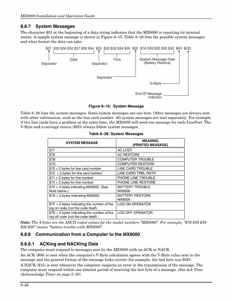
MX8000 Installation and Operation Guide
8–28
8.8.7 System Messages The character $01 at the beginning of a data string indicates that the MX8000 is reporting its internal status. A sample system message is shown in Figure 8–15. Table 8–28 lists the possible system messages and what format the data can take.
$01 $30 $36 $32 $37 $39 $34 $22 $30 $33 $34 $35 $22 $7A $39 $30 $30 $30 $63 $OD
Separator SeparatorDate Time
Separator
System Message Data(Battery Restore)
V=Byte
End Of MessageIndicator
Figure 8–15: System Message
Table 8–28 lists the system messages. Some system messages are one byte. Other messages are always sent with other information, such as the line card number. All system messages are sent separately. For example, if two line cards have a problem at the same time, the MX8000 will send one message for each LinePort. The V-Byte and a carriage return ($0D) always follow system messages.
Table 8–28: System Messages
SYSTEM MESSAGE MEANING (PRINTED MESSAGE)
$77 AC LOST $78 AC RESTORE $7B COMPUTER TROUBLE $7D COMPUTER RESTORE $70 + 2 bytes for line card number LINE CARD TROUBLE $72 + 2 bytes for line card number LINE CARD TRBL RSTR $71 + 2 bytes for line number PHONE LINE TROUBLE $73 + 2 bytes for line number PHONE LINE RESTORE $79 + 4 bytes indicating MX8000. (See Note below.)
BATTERY TROUBLE MX8000
$7A + 4 bytes indicating MX8000. BATTERY RESTORE MX8000
$7F + 2 bytes indicating the number of the log on code (not the code itself).
LOG ON OPERATOR
$7E + 2 bytes indicating the number of the log off code (not the code itself).
LOG OFF OPERATOR
Note: The 4 bytes are the ASCII coded values for the model numbers “MX8000”. For example, “$79 $39 $38 $30 $30” means “battery trouble with MX8000”.
8.8.8 Communication from a Computer to the MX8000
8.8.8.1 ACKing and NACKing Data The computer must respond to messages sent by the MX8000 with an ACK or NACK. An ACK ($06) is sent when the computer’s V-Byte calculation agrees with the V-Byte value sent in the message and the general format of the message looks correct (for example, the last byte was $0D). A NACK ($15) is sent whenever the computer suspects an error in the transmission of the message. The computer must respond within one timeout period of receiving the last byte of a message. (See Ack Time (Acknowledge Time) on page 5–19)

Section 8 – Automation Communication Formats
8–29
The MX8000 ignores any other communication from the computer when it is awaiting ACKing or NACKing. Generally, after two NACKs or two timeout periods of no response from the computer, the MX8000 generates a “computer trouble” message.
• If the computer ACKs the data, the MX8000 will send any additional data in its buffer.
• If the computer NACKs the data, the MX8000 will immediately re-send the data.
• If the computer NACKs a second time, the MX8000 will generate a computer trouble message.
• If the computer does not respond the second time the MX8000 sends the data, the MX8000 will generate a computer trouble message.
• If a backup automation device (printer or secondary automation system) is configured, the unacknowledged message will be sent to the device.
8.8.8.2 Link Test The automation computer may send a Link Test request to the MX8000 receiver to verify the communication link between the receiver and the automation computer. The MX8000 receiver will respond to each Link Test ($00) request with a NACK.
8.9 ITI Generic Computer Format
The ITI Generic Computer Output Format is designed to pass reported information through an RS-232 port to communicate with an automation computer. This format consists of four types of Generic Records--a Report Record, a Log Record, a Test Record, and an Okay Record.
8.9.1 Convention Used In This Section An ITI digit in this section is an ASCII representation of a number from 0 to 61 as follows:
Table 8–29: Number and ITI Digit Equivalent
Number Represented by ITI Digit
0 - 9 0 - 9 10 - 35 A - Z 36 - 61 a - z
8.9.2 Report Record A report record is an alarm report from a control panel to the receiver. The following is a general description of the information contained in a report record:
<$0A><"1"><"B"><"1"><$6A><"2345"><"8"><"b"><"45"><"A"><$0D>
Table 8–30: Report Record Components Character Byte Description
<$0A> 0 ASCII (0A hex) line feed character that marks the beginning of a record. <"1"> 1 Receiver ID digit. See Table 8–29 for value range. <"B"> 2 Phone line number digit. See Table 8–29 for value range. <"1"> 3 Most significant digit of account number. For example, A in account
AB-CDE. <$6A> 4 Control panel type/zone attribute code. See 8.9.2.1 for more information. <"2345"> 5-8 Lower 4 digits of the account number. For example, B-CDE in account AB-
CDE. <"8"> 9 Group number. See Table 8–29 for value range. <"b"> 10 User ID number. Will report 0 when a user number is not applicable. See
Table 8–29 for value range. <"45"> 11-12 Zone number. Two ASCII digits 00 - 99, A = 100, C = 110 <"A"> 13 Alarm condition. See Table 8–34 for alarm codes and descriptions. <$0D> 14 ASCII (0D hex) carriage return marking the end of the record.

MX8000 Installation and Operation Guide
8–30
8.9.2.1 Control Panel Type and Zone Attribution Byte Byte 4 (see Table 8–30) of the report record is divided into upper and lower nibbles. The upper nibbles (4 most significant bits) contain the code indicating the panel type.
Table 8–31: Upper Nibble Description
Upper Nibble Value
Description
2 Unknown Control Panel. 3 Non-ITI format 4 SX-III or SX-IVA 5 SX-IVB 6 SX-V 7 All other ITI panels.
The lower nibble (4 least significant bits) contains the code describing the zone attributes (unique with ITI panels). The definition of this field varies depending on which ITI panel the call was generated from. Refer to the installation manual of the ITI panel you wish to communicate with for communication specifications. If the upper nibble is 3 (non-ITI format), the lower nibble is used to identify the panel.
Table 8–32: Lower Nibble Description
Lower Nibble Value
Description
0 Anything not listed below 1 Slow 3/1 format 2 Fast 3/1 format 3 Slow 3/1 extended format 4 Fast 3/1 extended format 5 Slow 4/1 format 6 Fast 4/1 format 7 Slow 4/2 format 8 Fast 4/2 format 9 Radionics 3/1 hex format
$A Radionics BFSK
8.9.2.2 Extended Panel ID Codes When XID is set to Y in programming mode (see Section 5.4.3.5 page 5–20) the extended panel ID replaces the control panel type as described in Section 8.9.2.1. Table 8–33 lists the XID codes (both the Hex and the ASCII character) for the ITI Generic computer output.
Table 8–33: Extended Panel ID Codes (XID)
XID Code
Hex Character ASCII CharacterPanel Type
$40 @ SX-III $50 P SX-IVB $60 ‘ SX-V $70 p Other ITI panel $72 r SX-V Special $73 s Commander $74 t RF Commander $75 u CareTaker + $77 w Commander 2000 $78 x Security Pro 4000 $79 y UltraGard $7A z European Commander $7B { Simon $7E ~ New Panels
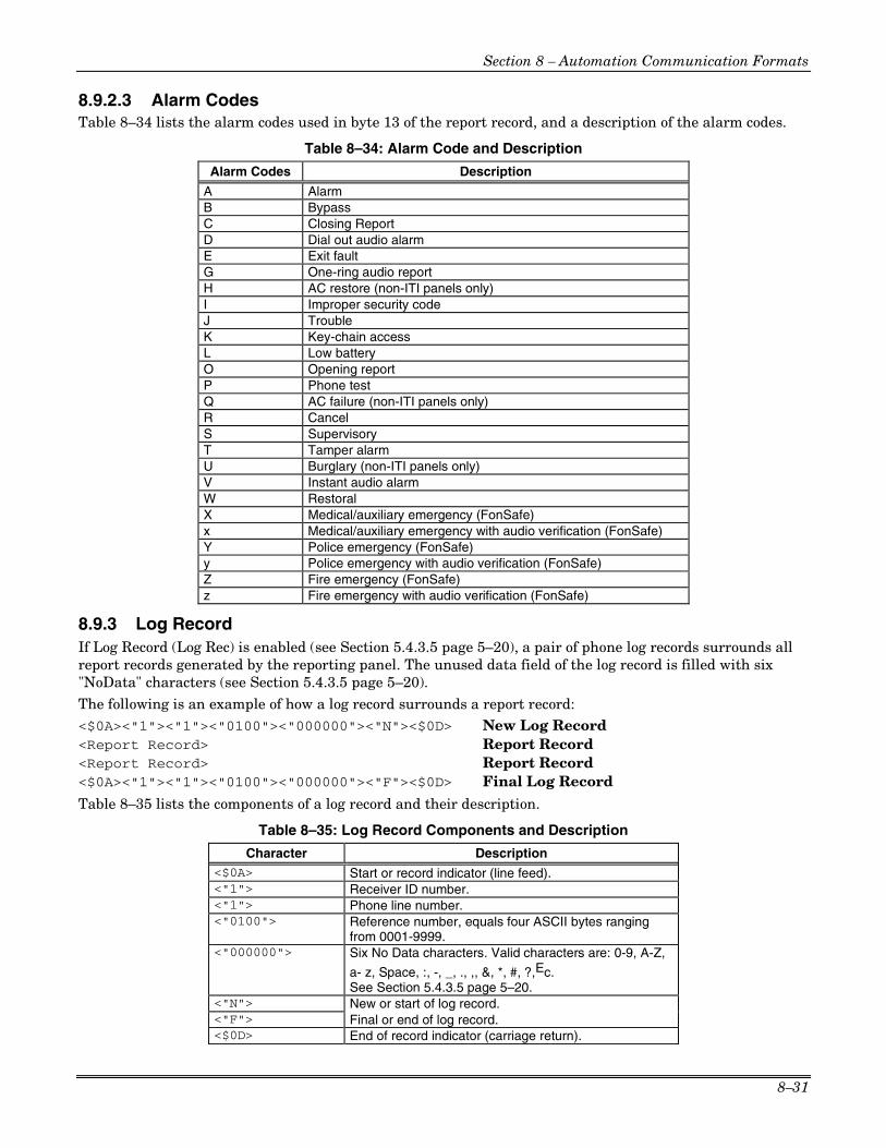
Section 8 – Automation Communication Formats
8–31
8.9.2.3 Alarm Codes Table 8–34 lists the alarm codes used in byte 13 of the report record, and a description of the alarm codes.
Table 8–34: Alarm Code and Description
Alarm Codes Description
A Alarm B Bypass C Closing Report D Dial out audio alarm E Exit fault G One-ring audio report H AC restore (non-ITI panels only) I Improper security code J Trouble K Key-chain access L Low battery O Opening report P Phone test Q AC failure (non-ITI panels only) R Cancel S Supervisory T Tamper alarm U Burglary (non-ITI panels only) V Instant audio alarm W Restoral X Medical/auxiliary emergency (FonSafe) x Medical/auxiliary emergency with audio verification (FonSafe) Y Police emergency (FonSafe) y Police emergency with audio verification (FonSafe) Z Fire emergency (FonSafe) z Fire emergency with audio verification (FonSafe)
8.9.3 Log Record If Log Record (Log Rec) is enabled (see Section 5.4.3.5 page 5–20), a pair of phone log records surrounds all report records generated by the reporting panel. The unused data field of the log record is filled with six "NoData" characters (see Section 5.4.3.5 page 5–20). The following is an example of how a log record surrounds a report record: <$0A><"1"><"1"><"0100"><"000000"><"N"><$0D> New Log Record <Report Record> Report Record <Report Record> Report Record <$0A><"1"><"1"><"0100"><"000000"><"F"><$0D> Final Log Record
Table 8–35 lists the components of a log record and their description.
Table 8–35: Log Record Components and Description
Character Description <$0A> Start or record indicator (line feed). <"1"> Receiver ID number. <"1"> Phone line number. <"0100"> Reference number, equals four ASCII bytes ranging
from 0001-9999. <"000000"> Six No Data characters. Valid characters are: 0-9, A-Z,
a- z, Space, :, -, _, ., ,, &, *, #, ?,Ec. See Section 5.4.3.5 page 5–20.
<"N"> New or start of log record. <"F"> Final or end of log record. <$0D> End of record indicator (carriage return).

MX8000 Installation and Operation Guide
8–32
8.9.4 Test Record A test record is sent when panel date/time is updated. The following is an example of a test record:
<$0A><"IT IRCV 234A"><$0D>
Table 8–36: Test Record Components and Description
Character Description
<$0A> Start of record (line feed). <"IT IRCV 234A"> Predefined test record string. The predefined test string is automatically set
when ITI Generic format is chosen to communicate with automation computer. <$0D> End of record indicator (carriage return).
8.9.5 OKAY Record When the automation computer sends a supervisory character to the MX8000 receiver, the receiver will return with an OKAY record. An OKAY record (heartbeat) is sent periodically to the automation computer. How often the OKAY record is sent is set through programming (see Section 5.4.3.5 page 5–18).
Note: The supervisory character is programmable. See Section 5.4.3.5 page 5–20.
The following is an example of an Okay record: <$0A><"00 OKAY @"><$0D>
Table 8–37: Okay Record Components and Description
Character Description
<$0A> Start of record (line feed). <"00 OKAY @"> Predefined okay record string. The predefined okay record string is
automatically set when ITI Generic format is chosen to communicate with automation computer.
<$0D> End of record indicator (carriage return).
8.9.6 ACKing and NACKing Data After the end of message byte (<0Dh>) is sent by the receiver, the automation computer will respond with an ACK (<$06>) or NACK (<$15>). This response can be delayed between 1 byte time (depending on the baud rate) and the ACK timeout period. See Section 5.4.3.5 page 5–19.
If the receiver doesn’t get an ACK within the ACK timeout period or receive a NACK from the automation computer, it will re-transmit the data.
After two NACKs or two ACK timeouts the receiver will generate a Computer Trouble message. When a computer trouble message is generated, the receiver will continually send a heartbeat until it receives an ACK from the automation computer. When communication is restored, a Computer Trouble Restore message will be generated.
8.10 ITI Computer Interface Format
ITI Computer Interface format consists of four types of records; report record, test record supervisory record, and log record (see Table 8–39).
8.10.1 Convention Used In This Section An ITI digit in this section is an ASCII representation of a number from 0 to 61 as follows:

Section 8 – Automation Communication Formats
8–33
Table 8–38: Number and ITI Digit Equivalent
Number Represented by ITI Digit
0 - 9 0 - 9
10 - 35 A - Z
36 - 61 a - z
8.10.2 General Record Structure Each record begins with <"|["><Record Type> field (see Table 8–39 for record identifiers) and ends with a <"]|"><Cksum/Ctrl> field. Any fields within a record may be included in an individual record as needed.
A record is made up of fields of data (in varying lengths), and each field within a record begins with a <"|"> character. The <"|"> is followed by a field identifying character. Individual field identifiers are unique to the specific record where they are contained. For example, a |L field in a report record has a different meaning than an |L field of a test record and so on. There is no specific order to the fields of a record, with the exception that it will begin with the record type and end with a checksum/control field.
After the checksum/control field each record is terminated with a carriage return (<$0D>).
Table 8–39: Type of Record Identifiers
Field Identifier Definition
[R Report record
[T Test record
[S Supervisory record
[L Log record
The following is a generic example of a transmitted message record: <"|["><Record Type><Info fields...><"|]"><Cksum/Ctrl><$0D>
Table 8–40: Record Components
Character Description
<"|["> Start of record indicator.
<Record Type> Record type. See Table 8–39.
<|Info fields...> Information fields. See Table 8–42.
<"|]"> End of information fields indicator.
<Cksum/Ctrl> Checksum/control field. See Section 8.10.7.
<$0D> End of record indicator.
8.10.3 Report Record A report record is generated when a control panel calls into the receiver for any reason. The following is an example report record (see also Table 8–41):
<"|["><"R"><"|IA1"><"|LB"><"|A123456"><"|V55600"><"|D0514"><"| T1019"><"N0005"><"|Z1"><"|CA"><"|]"><Cksum/Ctrl><$0D>
Table 8–41 lists the components of a report record and their description.

MX8000 Installation and Operation Guide
8–34
Table 8–41: Report Record Components and Description
Character Description
<"|["> Start of record indicator.
<R> Report record identifier.
<"|IA1"> Unit ID = A, followed by receiver ID = 1.
<"|LB"> Line Card #, B = 11. Acceptable values are 0-9, A (= 10), B (=11), C (=12).
<"|A123456"> Account Number.
<"|V55600"> Panel (see Table 8–43) and revision number. In this example the panel = SX-V and the revision is 5600.
<"|D0514"> Date of the report in mmdd format. mm = Month, dd = Day
<"|T1019"> Time of report in hhmm format. hh = Hour, mm = Minutes
<"N0005"> Reference number. See Section 4.6.3 0001-9999
<"|Z1"> Zone number. One to four alphanumeric characters are acceptable values.
<"|CA"> Condition code indicating the nature of the reported message. See Table 8–28.
<"|]"> End of information fields indicator.
<Cksum/Ctrl> Checksum/control field. See Section 8.10.7.
<$0D> End of record indicator.
8.10.3.1 Information Field Identifiers The following characters signify which data is contained in an information field:
Table 8–42: Information Field Identifiers
Field Identifier Description Acceptable Values
I System identifier. A unit ID (always an A) and the receiver ID digit. See 5.4.4.2 to set receiver ID.
"A" followed by 0-9.
O Communication Lock (Comm-Lock) usage. 0 = Not Supported (4)
1 = Phone lock
2 = Central Station Lock
3 = No lock used
M Audio (Listen-in) usage. 0 = Not Used (4)
1 = Instant mode
2 = Dial out mode
3 = One ring mode
L Line Card number. See Table 8–38 for acceptable values.
A Account number. Three to six alphanumeric characters. If the account is more than 6 characters the account will be truncated to the last six characters.
P Protection level of panel. Two bytes, the first indicates the previous protection level and the second indicates the current protection level.

Section 8 – Automation Communication Formats
8–35
Table 8–42: Information Field Identifiers (cont’d)
Field Identifier Description Acceptable Values
V Panel type and revision. One panel type code byte followed by a 4-digit revision number. See Table 8–43.
G Group and attribute information. Contact ITI for group and attribute information.
D Date of report. In mmdd format, where mm = month, and dd = day.
T Time of report In hhmm format, where hh = hour, and mm = minutes.
N Reference number. 0001-9999. See also Section 4.6.3.
Z Zone number. One to four alphanumeric characters.
U User number. See Table 8–38 for acceptable values.
K Dealer key numbers. For Commander 2000 only.
Values from 00-99.
S CPU sub-unit number Values from 0-9
C Condition code indicating the nature of the reported message. See Table 8–28.
See Table 8–28for condition code values.
8.10.3.2 Panel Type Characters The following table lists the characters used for panel types and which panel they refer to:
Table 8–43: Panel Type Characters
Character Panel Type Character Panel Type
0 Unknown type a 3/1
3 SX-III or SX-IVA e 3/1 extended
4 SX-IVB i 4/1
5 SX-V m 4/2
9 FonSafe r Radionics BFSK
A Commander s SIA DSC
B SX-V Special t Contact ID
C Magnetic card reader v ADEMCO TouchTone
D Euro Commander w Acron TouchTone
E Security Pro 4000 x Westec TouchTone
K HaborGard y ADEMCO DTMF 4/2
M UltraGard z ADEMCO DTMF 4/1
N Network Security # ADEMCO High Speed (SIA D1)
P Pin Point $ FSK 0
R RF Commander % FSK 1
S Commander 2000 or LifeGard & FSK 2
T CareTaker + ( FBII 4/3/1
V Protector
Z Nutone

MX8000 Installation and Operation Guide
8–36
8.10.3.3 Condition Codes Condition codes are a one-digit character that indicates the nature of the call from a control panel to the receiver.
Table 8–44 lists the different condition codes and their descriptions:
Table 8–44: Condition Codes and Descriptions
Condition Code Description
A Alarm
B Bypass
C Closing Report
E Exit Fault
F Force Arm
G Burglary (non-ITI panels only)
H AC Restore (non-ITI panels only)
I Improper Security Code
J Trouble
L Low battery
M Medical/Auxiliary Emergency
N Fire Emergency
O Opening Report
P Power Failure (non-ITI panels only)
Q Police Emergency
R Restoral
S Supervisory
T Tamper
U Status Report (non-ITI panels only)
X Cancel
Z Phone Test
c Key Access Closing Report
o Key Access Opening Report
8.10.4 Test Record A test record is sent when the panel date/time is updated.
The following is an example of a test record: <"|["><"T"><"|IA1"><"|D970514"><"|T145056"><"|V042097"><"|L6.1"><"|]"> <Cksum/Ctrl><$0D>
Table 8–45 lists the information fields contained in a test record and their descriptions:
Table 8–45: Test Record Information Fields and Descriptions
Character Description Acceptable Values
I System identifier. A unit ID (always an A) and the receiver ID digit. See 5.4.4.2 to set receiver ID.
"A" followed by 0-9.
D Date Current date in yymmdd format yy = year, mm = month, dd = day.
T Time Current time in hhmmss format hh = hours, mm = minutes, ss = seconds.
V Software version In date format.
L ITIComp revision level. Two digits separated by a decimal point.

Section 8 – Automation Communication Formats
8–37
8.10.5 Supervisory Record When the automation computer sends a supervisory character to the receiver, the receiver will answer with a supervisory record. A supervisory record (heartbeat) is sent periodically to the automation computer. How often the supervisory record is sent is set through programming (see Section 5.4.3.5 page 5–18).
The following is an example of a supervisory record: <"|["><"S"><"|IA1"><"|D970514"><"|T145056"><"|V042097"><"|L6.1"><"|]"> <Cksum/Ctrl><$0D>
Table 8–45 lists the information fields contained in a test record and their descriptions.
8.10.6 Log Records If Log Record (Log Rec) is enabled (see Section 5.4.3.5 page 5–20), a pair of phone log records surrounds all report records generated by the reporting panel. The unused data field of the log record is filled with six "NoData" characters (see Section 5.4.3.5 page 5–20).
The following is an example of how a log record surrounds a report record:
<"|["><"L"><"|IA1"><"|L1"><"|Nooo1"><"|S970425080020"><"|]"><Cksum/Ctrl><$0D> Start Log Rec
<Report Record> Report Rec
<Report Record> Report Rec
<"|["><"L"><"|IA1"><"|L1"><"|Nooo1"><"|E970425080110"><"|]"><Cksum/Ctrl><$0D> End Log Rec
Table 8–46 lists the information fields contained in a log record and their descriptions.
Table 8–46: Log Record Information Fields and Descriptions
Character Description Acceptable Values
I System identifier. A unit ID (always an A) and the receiver ID digit. See 5.4.4.2 to set receiver ID.
"A" followed by 0-9.
L Line Card number. See Table 8–38 for accepted values.
N Reference number. 0001-9999
S Date and time. YYMMDDhhmmss format where YY = Year, MM = Month, DD = Day, hh = hour, mm = minutes, dd = seconds.
E Date and time. YYMMDDhhmmss format where YY = Year, MM = Month, DD = Day, hh = hour, mm = minutes, dd = seconds.
8.10.7 Checksum/Control Field The last field of every record is the checksum/control field. This field contains an upper case letter followed by four ASCII hexadecimal digits. Contained in these five characters are three controls to help guarantee data integrity between the receiver and the automation computer. The first control is the Sequence Control Character (SCC). This is a letter code which cycles from "A" to "Z" continually, changing successively with each new record transmitted.
Note: If the receiver has to repeat a record in response to a NACK from the automation computer, the same SCC is sent both times.
The first digits sent (following the SCC) are the two least significant digits of an additive checksum for the record from the first "|" character up to and including the SCC. See Table 8–47. The last two digits in the record are an XOR checksum. The XOR checksum starts with a value FFh. This value is XORed against the first byte in the record. The result is XORed against the next byte and so on, up through the SCC. See Table 8–47. The following is an example of a checksum/control field:
|[X|]A49E0
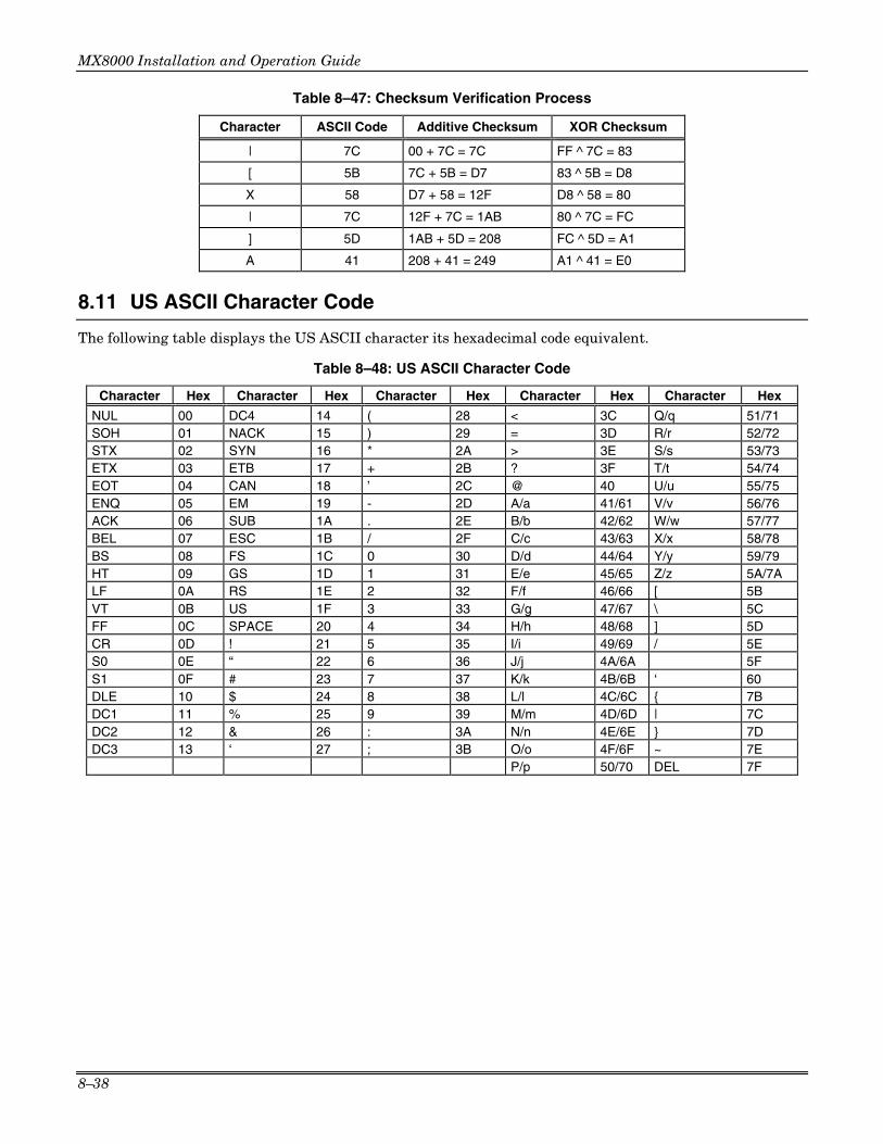
MX8000 Installation and Operation Guide
8–38
Table 8–47: Checksum Verification Process
Character ASCII Code Additive Checksum XOR Checksum
| 7C 00 + 7C = 7C FF ^ 7C = 83
[ 5B 7C + 5B = D7 83 ^ 5B = D8
X 58 D7 + 58 = 12F D8 ^ 58 = 80
| 7C 12F + 7C = 1AB 80 ^ 7C = FC
] 5D 1AB + 5D = 208 FC ^ 5D = A1
A 41 208 + 41 = 249 A1 ^ 41 = E0
8.11 US ASCII Character Code
The following table displays the US ASCII character its hexadecimal code equivalent.
Table 8–48: US ASCII Character Code
Character Hex Character Hex Character Hex Character Hex Character Hex
NUL 00 DC4 14 ( 28 < 3C Q/q 51/71 SOH 01 NACK 15 ) 29 = 3D R/r 52/72 STX 02 SYN 16 * 2A > 3E S/s 53/73 ETX 03 ETB 17 + 2B ? 3F T/t 54/74 EOT 04 CAN 18 ’ 2C @ 40 U/u 55/75 ENQ 05 EM 19 - 2D A/a 41/61 V/v 56/76 ACK 06 SUB 1A . 2E B/b 42/62 W/w 57/77 BEL 07 ESC 1B / 2F C/c 43/63 X/x 58/78 BS 08 FS 1C 0 30 D/d 44/64 Y/y 59/79 HT 09 GS 1D 1 31 E/e 45/65 Z/z 5A/7A LF 0A RS 1E 2 32 F/f 46/66 [ 5B VT 0B US 1F 3 33 G/g 47/67 \ 5C FF 0C SPACE 20 4 34 H/h 48/68 ] 5D CR 0D ! 21 5 35 I/i 49/69 / 5E S0 0E “ 22 6 36 J/j 4A/6A 5F S1 0F # 23 7 37 K/k 4B/6B ‘ 60 DLE 10 $ 24 8 38 L/l 4C/6C { 7B DC1 11 % 25 9 39 M/m 4D/6D | 7C DC2 12 & 26 : 3A N/n 4E/6E } 7D DC3 13 ‘ 27 ; 3B O/o 4F/6F ~ 7E P/p 50/70 DEL 7F

A–1
Appendix A Programming Quick Chart
Table A–1: Programming Quick Chart
Program Mode Options Choices Choices Choices Choices Comments
Manual
Automatic Operation Mode
Log Only
See Section 4.5 for description of modes of operation. See also Section 5.4.1.
English See Section 5.4.2 for details. Language
español
Not available at this time.
AMPM 12-hour clock. See Section 5.4.2.2 for details.
Time Format 24Hr
24-hour clock. See Section 5.4.2.2 for details.
M\D\Y
D·M·Y Date Format
Y-M-D
See Section 5.4.2.3 for details. M = month, D = day, Y = year.
Yes Change Hour, Start Month, Start Week, End Month, End Week
Daylight Savings
No
See Section 5.4.2.4 for details.
Attempts Yes or No
CPU Time Yes or No
CPU Type Yes or No
Panel Rev Yes or No
ITI Options
Arming Level Yes or No
See Section 5.4.2.5 Affects printer and VFD output only.
Code FSK1
English
Code
BSFK English
If “English” is selected then the printer and VFD output for calls of these formats will be text descriptions. If “Code” is selected then the printer and VFD output for calls of these formats will be the Code and Zone numbers. See Section 5.4.2.6 for step-by-step instructions.
Code
SIA English
If “English” is selected, the printer and VFD output will be text. If “Code” is selected then the printer and VFD will display the SIA codes followed by zone or other information.See Section 5.4.2.6 for step-by-step instructions.
Code
General Options
Display Options
Format Config.
CID
English This option only affects the ADEMCO 8000 automation protocol output. If “English” is selected each event will be sent to the automation as two SIA events; the first with the two digit Group number and the second with the three digit ID number. If “Code” is selected, each event is sent as eleven digits; two digits Message type, one-digit Event Qualifier, three-digit Event Code, two-digit Group Number, and three-digit ID number. See Section 5.4.2.6 for step-by-step instructions.

MX8000 Installation and Operation Guide
A–2
Table A–1: Programming Quick Chart (cont’d) Program Mode
Options Choices Choices Choices Choices Comments
0 .. 9 PULSE
0 .. F
Packed SK9000
Unpacked
Zero ACRON
Space
SIA
Format Config. (continued)
HISPEED Hispeed
Yes Hold last event
No
See Section 5.4.2.7.
Off
25%
50%
75%
Display Options (continued)
VFD Brightness
MAX
Affects main menu display only. All other displays are always at maximum.
See Section 5.4.2.8 for details.
Com1 Unused/Automation/Printer/
Com2 Unused/[Auto Bkp]/[Auto Bkp Prn]/{Print Bkp}/Diag/Printer Port Functions
Par (Parallel) Unused/[Auto Bkp]/Printer/Diag
Rules for Port Configuration:
1. Functions in Brackets [ ] will not appear unless “Automation” is selected for Com1 function.
2. Functions in { } will not appear unless “Printer” is selected in Com1 or Par.
3. A function may be selected only once in the 3 ports (only one printer, only one Diag, and so on).
4. All ports may be configured “Unused”.
Baud 38400, 19200, 9600, 7200, 4800, 2400, 1200, 600, 300, 110
D (# Data Bits) 8, 7
S (# Stop bits) 1 or 2
P (Parity) Even, Odd, No
PortMon Yes, No
F (Flow Control) Hdwr, None, Software
See Section 5.4.3.2 for details.
Com Port 1
Init Str (Initialization String)
Enter ASCII characters for the Escape command sequence desired. For example: Set the page size or number of lines per page for a serial printer.
Com Port 2 Same as Com 1
Edit Init String Enter or edit an Escape command sequence. For example: Set the page size or number of lines per page for a printer.
General Options (continued)
Communication
Par Port
Clear Init String

Appendix A – Programming Quick Chart
A–3
Table A–1: Programming Quick Chart (cont’d) Program Mode
Options Choices Choices Choices Choices Comments
Format CAPS, SK9000, ADEM 8000, ADEM 685, FBII 220, ITI Gen, ITIComp
See Section 5.4.3.5 for details.
Y (yes) Hex
N (no)
Feature is only available if ADEM 8000 or SK9000 automation protocol is selected.
Y (yes) Heartbeat
N (no)
Time (of heartbeat)
10-600 seconds
Ack timeout 1-120 seconds
Term Char = 013
Head Char = 010
ACK Char = 006
NACK Char = 021
TR = 005
TH = 084
CFG
TT = 020
Feature is only available if ADEMCO 685, FBII CP-220, or CAPS ONLY is selected. Allows automation characters to be entered.
Y = Enabled SEP
N = Disabled
Only visible if SK9000 format selected. Sets account separator to hex 05 or 2E.
Y = Enabled Log Records N = Disabled
Y = Enabled Enable Ext ID N = Disabled
Super Character
No Data Character
6.1
Automation Cfg.
ITI
Generic Revision 6.2
Only visible if ITI Gen or ITIComp format is selected.
Printer Yes or No
Bkp Printer Yes or No
Auto Comp Yes or No
Bkp Auto Comp Yes or No
Battery Yes or No
See Section 5.4.3.6 for details. Yes = alert on trouble indication
Device Yes or No Device corresponds to loss of com-munication with slave or line card.
Line Fault Yes or No
AC Power Yes or No
Buffer Full Yes or No
Listen In Yes or No Listen in must be set to No for UL installations.
Annunciator Configuration
Call Pending Yes or No
Printer Yes or No
Bkp Printer Yes or No
Auto Comp Yes or No
Bkp Auto Comp Yes or No
Battery Yes or No
See Section 5.4.3.7 for details. Yes = alert on trouble indication
Device Yes or No Device corresponds to loss of com-munication with slave or line card.
Line Fault Yes or No
AC Power Yes or No
Buffer Full Yes or No
Listen In Yes or No Listen in must be set to No for UL installations.
General Options (continued)
Communication (continued)
Aux Relay Cfg
Call Pending Yes or No
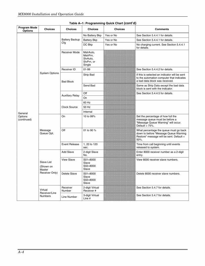
MX8000 Installation and Operation Guide
A–4
Table A–1: Programming Quick Chart (cont’d) Program Mode
Options Choices Choices Choices Choices Comments
No Battery Bkp Yes or No See Section 5.4.4.1 for details.
Battery Bkp Yes or No See Section 5.4.4.1 for details. Battery Backup Cfg
DC Bkp Yes or No No charging current. See Section 5.4.4.1 for details.
Receiver Mode MstrAuto, MstrPrn, SlvAuto, SlvPrn, or Single
Receiver ID 01-99 See Section 5.4.4.2 for details.
Strip Bad If this is selected an indicator will be sent to the automation computer that indicates a bad data block was received. Bad Block
Send Bad Same as Strip Data except the bad data block is sent with the indicator.
Off Auxiliary Relay
On
See Section 5.4.4.5 for details.
60 Hz
50 Hz
System Options
Clock Source
Internal
On 10 to 99% Set the percentage of how full the message queue must be before a “Message Queue Warning” will occur. Default = 75%.
Off 01 to 90 % What percentage the queue must go back down to before “Message Queue Warning Restore” message will be sent. Default = 50%.
Message Queue Opt.
Event Release 1, 20 to 120 sec.
Time from call beginning until events released to system.
Add Slave 2-digit Slave No.
Enter 8000 receiver number as a 2-digit entry.
View Slave S01=8000 Slave S02=8000 Slave
View 8000 receiver slave numbers. Slave List
(Shown on Master Receiver Only) Delete Slave S01=8000
Slave S02=8000 Slave
Delete 8000 receiver slave numbers.
Receiver Number
2-digit Virtual Receiver #
See Section 5.4.7 for details.
General Options (continued)
Virtual Receiver/Line Numbers Line Number
3-digit Virtual Line #
See Section 5.4.7 for details.

Appendix A – Programming Quick Chart
A–5
Table A–1: Programming Quick Chart (cont’d) Program Mode
Options Choices Choices Choices Choices Choices Comments
Use Defaults Add Device
Device # Copy Existing
See Section 5.5.1 for details.
Handshake Sequence
1 through 6
Format Group
1400_2300–2, 1400Hz, 2300Hz, 2225Hz, Modem II, Modem IIE, Westec, 1400_2300Hz, or Unused
Handshake Duration
0-9999 in 1ms periods
Handshake Wait
0-9999 in 1ms periods
Handshake Sequence
Handshake Ack Duration
0-9999 in 1ms periods
See Section 5.5.2.1 for details.
5-Digit Format 4/1, 3/2, 3/1CS CS = Check Sum. If a pulse comes in a 5-digit format then the data will then be treated as the selected format.
6-Digit Pulse 4/2, 3/2CS, 4/1CS CS = Check Sum. If a pulse comes in a 6-digit format then the data will then be treated as the selected format.
Inter-digit Tm (ms)
0 or 1 ms to 2 Sec. This feature selects the time period between data blocks. See Section 5.5.2.2 for details.
Ack on Even Round
Yes or No If “Yes” Acknowledge only on even rounds.
Pulse Format
Partially Extended
Yes or No If “Yes” you have multiple extended data blocks for 3/1 or 4/1 format.
Y (yes) Direct N (no)
Y = dedicated or direct connect phone line. N = used for standard phone lines.
Number of Rings
0-255
Country Country of choice
See Section 5.5.2.3 for details.
Threshold 0-15 in 2.75VDC steps
Line Options
Sample Time 0-90 seconds
Listen In Mode Common, PBX, Not Used
PBX string edit screen
Up to 20 characters.
Timeout 0-255 seconds? Listen In
Listen In account edit screen
Add, Edit, or Clear Account.
See Section 5.5.2.4 for details.
Y (yes) Echo Suppress
N (no)
Y (yes) Caller ID
N (no)
On Billing Delay
Off
Hunt Group 00-99
Min Ring (15-99)
Max Ring (015-100)
Ring Off (1500-8000)
Min Ring Off (100-800)
Ring Error (0800-4400)
Ring Options
Min # Ring Per (01-20)
Line Device Menu
MX8000–LC3 3 Line
Edit Line+ Line #
Misc. Line Options
Call Hang-up 60-180 sec
See Section 5.5.2.5 for details.

MX8000 Installation and Operation Guide
A–6
Table A–1: Programming Quick Chart (cont’d) Program Mode
Options Choices Choices Choices Choices Choices Comments
BFSK Auto HiSpeed or 4/2 3/1 Restore HiSpeed or 3/1 4/2 Out Normal or HiSpeed FBI S/Fast or LAR300 Pulse Extended Extended or Not Ext.
Ademco Auto Opt
Extended Out HiSpeed or 4/2
See Section 5.5.2.6 for details
Transmit Gain –3 to –14dB Receive Gain 0 to 12dB in 3dB steps
CID Monitor Norm, Pream, DTMF, or Marks
CID Gain –6 to 7dB in steps On Hook Gain 2 to 7dB in steps
Edit Line+ Line # (con-tinued)
Line Gain Opt
Ringer Imped Hi or Sy
See Section 5.5.2.7 for details.
Use Defaults
Choose Device(s) #
Choose Device(s) # that you wish to be programmed to factory defaults.
Copy Device(s) Copy
Existing Device # of Source Device
Choose the target Device(s) #.
Copy the programming of one Device (source) and paste it into one or several (target) Device(s).
Clear Device(s)
Device # See Section 5.5.6 for details.
MX8000–LC3 3 Line (con-tinued)
View Device(s)
Device # See Section 5.5.7 for details.
Add Device
Device # Use Defaults See Section 5.5.1 for details.
Central Station #
00-FF
Odd/Even Network
Odd/Even
VPN Yes/No A/B Network
A/B
Edit Line+ Line #
Monitor Station Flag
Yes/No
Use Defaults
Choose Device(s) #
Choose Device(s) # that you wish to be programmed to factory defaults.
Copy Device(s) Copy
Existing Choose Device # of Source Device
Choose the target Device(s) #.
Copy the programming of one Device (source) and paste it into one or several (target) Device(s).
Clear Device(s)
Choose Device #
See Section 5.5.6 for details.
MX8000–LRR
View Device(s)
Choose Device #
See Section 5.5.7 for details.
Use Defaults Add Device
Device # Copy Existing
See Section 5.5.1 for details.
Handshake Sequence
1 through 6
Handshake Group
1400_2300–2, 1400Hz, 2300Hz, 2225Hz, Modem II, Modem IIE, Westec, 1400_2300Hz, or Unused
Handshake Delay
0-255 in 50ms periods
Handshake Duration
0-255 in 10ms periods
Handshake Wait
0-255 in 50ms periods
Line Device Menu (continued)
MX8000–LC1 1 Line
Edit Line+ Line #
Handshake Sequence
Handshake Ack Duration
0-255 in 10ms periods
See Section 5.5.4.1 for details.

Appendix A – Programming Quick Chart
A–7
Table A–1: Programming Quick Chart (cont’d) Program Mode
Options Choices Choices Choices Choices Choices Comments
5-Digit Format 4/1, 3/2, 3/1CS CS = Check Sum. If a pulse comes in a 5-digit format then the data will then be treated as the selected format.
6-Digit Pulse 4/2, 3/2CS, 4/1CS CS = Check Sum. If a pulse comes in a 6-digit format then the data will then be treated as the selected format.
Inter-digit Tm (ms)
0 or 1 ms to 2 Sec. Selects the time period between data blocks. See Section 5.5.4.2 for details.
Ack on Even Round
Yes or No If “Yes” Acknowledge only on even rounds.
Pulse Format
Partially Extended
Yes or No If “Yes” you have multiple extended data blocks for 3/1 or 4/1 format.
Y (yes) Direct N (no)
Y = dedicated or direct connect phone line. N = used for standard phone lines.
Number of Rings
0-255
On Time 0-255 in 50ms periods
Off Time 0-255 in 50ms periods
See Section 5.5.4.3 for details.
Lo (Low)
Hi (High) dB Level
Md (Medium)
Select the dB level of the Handshakes and Acknowledge tone.
Threshold 0-15 in 2.00VDC steps
Line Options
Sample Time 0-255 seconds.
Listen In Mode Common, PBX, Not Used
PBX string edit screen
Up to 20 characters.
Timeout 0-255 seconds? Listen In
Listen In account edit screen
Add, Edit, or Clear Account.
See Section 5.5.4.4 for details.
Y (yes) Echo Suppress
N (no)
Y (yes) Caller ID
N (no)
On Billing Delay
Off
Hunt Group 00-99
Misc. Line Options
Call Hang-up 60-180 sec
See Section 5.5.4.5 for details.
BFSK Auto HiSpeed or 4/2
3/1 Restore HiSpeed or 3/1
4/2 Out Normal or HiSpeed
FBI S/Fast or LAR300
Pulse Extended Extended or Not Ext.
Edit Line+ Line # (con-tinued)
Ademco Auto Opt
Extended Out HiSpeed or 4/2
See Section 5.5.4.6 for details.
Use Defaults
Choose Device(s) #
Choose Line Device(s) # that you wish to be programmed to factory defaults.
Copy Device(s) Copy
Existing Choose Device # of Source Device
Choose the target Device(s) #.
Copy the programming of one Device (source) and paste it into one or several (target) Devices.
Clear Device
Device # See Section 5.5.6 for details.
Line Device Menu (continued)
MX8000–LC1 1 Line (con-tinued)
View Device
Device # See Section 5.5.7 for details.

MX8000 Installation and Operation Guide
A–8

B–1
Appendix B Receiver Update Procedure A receiver update may be issued by when necessary. These updates are supplied either as a download from a web site or on floppy disk.
!WARNING!
• It is recommended that you make a printout of your programmed values for reprogramming after the update is complete. To make a printout of the programmed values, see “How to Print System Configuration” on page 4–13 and perform a Print All operation.
• The MX8000 Receiver will not accept any calls while the update procedure is being performed.
ITEMS NEEDED TO COMPLETE APPLICATION UPDATE
The following items must be available before starting the update.
• PC with available COM Port. • 9 pin to 9 pin null modem serial cable. (Female end for Receiver Com Port.)
Note that a null modem cable will normally be required. On some computers it is possible to order the serial com port configured for a hard-wire connection. If you have exercised this option, use a normal 9 pin to 9 pin serial cable.
• Update software.
UPDATE PROCEDURE
To update the MX8000 Receiver, perform the following procedure: 1. With the MX8000 Receiver POWERED OFF, connect the null modem cable to the “COM 2” port of the
Receiver and the other end to the “COM 1” port on the PC.
Note: If the COM 1 port is not available on your PC you must edit the “bat” file supplied with the update software. To edit the “bat” file, see EDITING THE BAT FILE on page B–2 and then continue with step 2 below.
2. From the Windows Start menu, choose the run command and then select and run the “Bat” file that is part of the update software. The screen will display: Connect cable between PC COM1 and device. Power up the device.
3. Power up the Receiver. The update will begin.
Notes:
•••• If the current application in the Receiver must be erased, the BAT file will automatically send an “erase_app.txt” file to the receiver prior to sending the update file.
•••• While data is being transferred, the VFD may display a message “Key Bus Trouble”. This is normal due to timing and the message will be cleared after the system reset is complete.
When the update has been transferred to the receiver, the screen will display: Transfer Successfully Completed
4. Power off the Receiver 5. Disconnect the cable between the “COM 1” port on the PC and the “COM 2” port of the Receiver
6. Power up the Receiver 7. If instructed to do a reset in your update package, once the Receiver has completed its initialization, log
onto the Receiver and select “System Reset” which is option 5 in the Installer Menu. Answer “Yes” when the system shutdown and default setting message is displayed.

MX8000 Installation and Operation Guide
B–2
EDITING THE BAT FILE You must edit the “bat” file supplied with your upgrade software if you are not able to use the COM 1 port on your computer. To edit the bat file:
1. In Windows, load Notepad. 2. In Notepad, select “File” and then select “Open” from the drop-down menu. 3. In the Notepad “Files of type:” window select All Files. 4. Change the folder in Notepad to match the folder where your update software is stored. The “bat” file
name should be displayed. 5. Select the “bat” file and the screen will appear similar to the below display. App_Update -cCOM1 -eerase_app.txt -aP124060VB1.51.lzs
6. Edit the –cCOM1 command to match the COM port you are using. (DO NOT DELETE the –c as it defines the that the following characters are the COM port name.) For example, if you are using COM port 2, your display will be similar to the below display.
App_Update -cCOM2 -eerase_app.txt -aP124060VB1.51.lzs
7. Do a File Save in Notepad and then do a File Exit. Your modified “bat” file is ready for use.
8. Return to the UPDATE PROCEDURE on page B–1.

C–1
Appendix C Index 240 VAC ................................................................................. 3–9 3/1 Restore Out
MX8000-LC1.................................................................... 5–67 MX8000-LC3.................................................................... 5–50
4/2 Out MX8000-LC1.................................................................... 5–67 MX8000-LC3.................................................................... 5–50
Accessories............................................................................. 1–1 ACKing
ADEMCO 8000................................................................... 8–9 ITI Generic........................................................................ 8–32 SK9000............................................................................. 8–28
Acknowledge Time................................................................ 5–19 Acknowledge Tone Duration Time
MX8000-LC1 .................................................................... 5–58 MX8000-LC3 .................................................................... 5–40
Add Slave.............................................................................. 5–26 ADEMCO 8000 ....................................................................... 8–3
ACKing ............................................................................... 8–9 Bad Data............................................................................. 8–6 Dialer format ....................................................................... 8–4 NACKing............................................................................. 8–9
Annunciator........................................................................... 5–14 Automatic operation ................................................................ 5–6 Automation Communication Format .............................. 5–17, 8–1 Automation Computer Connection......................................... 3–12 Automation Configuration............................................ 5–13, 5–14 Automation Protocols .............................................................. 8–1 Auxiliary Relay .............................. 3–1, 5–15, 5–21, 5–22, 5–24 Backup Battery
Configuration .................................................................. 5–22 Connection ....................................................................... 3–11 Setting .............................................................................. 5–22
Bad Data............................................................................... 8–27 ADEMCO 8000................................................................... 8–6 SK9000............................................................................. 8–27
BFSK Auto Out MX8000-LC1.................................................................... 5–67 MX8000-LC3.................................................................... 5–49
Call Hang-up ............................................................... 5–49, 5–66 Call Message .......................................................................... 8–3 Caller ID
MX8000-LC1 .................................................................... 5–65 MX8000-LC3 .................................................................... 5–47
Calls From Panels................................................................. 8–26 checksum/control field........................................................... 8–37 CID Gain
MX8000-LC3.................................................................... 5–52 CID Monitor
MX8000-LC3.................................................................... 5–52 Clock Synchronization........................................................... 5–24 Com Port 1.........................................................3–12, 5–12, 5–15 Com Port 2.........................................................5–12, 5–13, 5–16 communication option ........................................................... 5–12 computer port baud rate ........................................................ 3–12 Condition Codes.................................................................... 8–36 Configure Printer ................................................................... 4–15 Country
MX8000-LC3 .................................................................... 5–43 Current Draw.......................................................................... 3–1 Data String ............................................................................ 8–25 Date Display............................................................................ 5–7 Date Format Display ............................................................. 5–9 Daylight Savings ............................................................. 5–7, 5–9 Dedicated Line
MX8000-LC1.................................................................... 5–60
MX8000-LC3 ....................................................................5–42 Default User Codes .................................................................4–5 delete a user..........................................................................5–73 Delete Slave ..........................................................................5–27 Direct Line
MX8000-LC1 ....................................................................5–60 MX8000-LC3 ....................................................................5–42
Disable Line Device .....................................................5–42, 5–60 Display options ........................................................................5–7 earth ground ..........................................................................3–10 Edit Line Device
MX8000-LC1 .....................................................................5–56 MX8000-LC3 .....................................................................5–38 MX8000-LRR ....................................................................5–53
Event Release .......................................................................5–26 Extended Out
MX8000-LC1 ....................................................................5–68 MX8000-LC3 ....................................................................5–51
FBII Out MX8000-LC1 ....................................................................5–67 MX8000-LC3 ....................................................................5–50
FCC Registration Number........................................................2–1 Features ..................................................................................1–1 firmware information ................................................................4–9 Format Group
MX8000-LC1 ....................................................................5–57 MX8000-LC3 ....................................................................5–40
Formats ...................................................................................1–2 Fuse .......................................................................................3–1 General Options.......................................................................5–2 General Options Items .............................................................5–3 Grounding..............................................................................3–10 Handshake Delay
MX8000-LC1 .....................................................................5–57 Handshake Duration
MX8000-LC1 .....................................................................5–58 MX8000-LC3 .....................................................................5–40
Handshake Sequence MX8000-LC1 .....................................................................5–57 MX8000-LC3 .....................................................................5–39
Handshake Wait MX8000-LC1 .....................................................................5–58 MX8000-LC3 .....................................................................5–40
Hang-Up ................................................................................8–11 Heartbeat.......................................................................5–18, 8–8 hexadecimal values .................................................................8–1 Hold Last Event .............................................................5–8, 5–11 Initialization string (Init string).................................................5–16 ITI Computer Information Format ...........................................5–19 ITI Computer Interface Format...............................................8–32 ITI Formats ..........................................................................5–20 ITI Generic......................................................... 5–19, 8–29, 8–30
ACKing..............................................................................8–32 NACKing ...........................................................................8–32
ITI Panels .............................................................................5–20 Language .............................................................................. 5–7 Language Display...................................................................5–8 LED .........................................................................................4–3 Line Card Installation ...............................................................3–5 Line Device..................................................................5–28, 5–38
Disable ....................................................................5–42, 5–60 Line Options
MX8000-LC1 .....................................................................5–60 MX8000-LC3 .....................................................................5–42
Line Voltage............................................................................3–1 Link Test......................................................................8–13, 8–29

MX8000 Installation and Operation Guide
C–2
Listen-in ........................................................................ 4–19, 8–5 ADEMCO 8000....................................................... 8–11, 8–12
Listen-in Add MX8000-LC1 .................................................................... 5–64 MX8000-LC3 .................................................................... 5–45
Listen-in Clear MX8000-LC1.................................................................... 5–64 MX8000-LC3.................................................................... 5–46
Listen-in Edit MX8000-LC1.................................................................... 5–64 MX8000-LC3.................................................................... 5–46
Log Off ............................................................................ 4–5, 4–6 Log On .................................................................................... 4–5 Log only operation................................................................... 5–6 Log Record ................................................................. 8–31, 8–37 Long Call....................................................................... 8–6, 8–26 Main Menu .............................................................................. 4–7 Main Menu Option Items by Profile.......................................... 4–5 Maneuver Around in Program Mode........................................ 5–2 Maneuver Through Main Menu................................................ 4–8 Manual (Common) Listen-in .................................................. 4–19 Manual operation ...................................................................5–6 master/slave receiver linking ................................................. 3–12 model number ......................................................................... 4–9 NACKing
ADEMCO 8000................................................................... 8–9 ITI Generic........................................................................ 8–32 SK9000............................................................................. 8–28
No Data Received ................................................................... 7–4 Normal mode .......................................................................... 4–6 Null Modem Cable
25-Pin ............................................................................... 3–12 9-Pin ................................................................................. 3–12
Number of Rings MX8000-LC1 .................................................................... 5–60 MX8000-LC3 .................................................................... 5–42
OKAY Record ....................................................................... 8–32 On Hook Gain
MX8000-LC3.................................................................... 5–53 On-board Annunciator ........................................................... 5–20 Operation mode ...................................................................... 5–6 Panel data............................................................................... 8–4 Panel Type Characters.......................................................... 8–35 Parallel Port .......................................................................... 5–13 PBX....................................................................................... 4–20 PBX String .................................................................. 4–20, 8–12 Phone Line Sample Rate
MX8000-LC1 .................................................................... 5–62 PIN..................................................... 1–4, 4–5, 5–71, 5–72, 5–73 Port Function........................................................5–4, 5–12, 5–15 Power Up ................................................................................ 4–4 Print a Test Page .................................................................. 4–13 Print Call History ................................................................... 4–12 Print Line Card Statistics ....................................................... 4–14 print menu............................................................................. 4–11 Print Report........................................................................... 4–12 Print System Configuration.................................................... 4–13 Print System History.............................................................. 4–12 printer cable ............................................................................ 3–8
Program Menu.......................................................................4–16 Programming ...........................................................................5–1 Programming Choices .............................................................5–2 Programming Fields.................................................................5–1 Pulse Extended
MX8000-LC1 ....................................................................5–68 MX8000-LC3 ....................................................................5–50
Quick Start...............................................................................3–1 Receive Line Gain
MX8000-LC3 ....................................................................5–51 Receiver ID........................................................ 4–9, 5–22, 5–23 Receiver Master.....................................................................5–23 Receiver Single......................................................................5–23 Receiver Slave.......................................................................5–23 Record Structure....................................................................8–33 Report Record .......................................................................8–33 Ring Off Time
MX8000-LC1 .....................................................................5–61 Ring On Time
MX8000-LC1 .....................................................................5–61 Ring Threshold
MX8000-LC1 .....................................................................5–61 MX8000-LC3 .....................................................................5–43
Ringer Impedance MX8000-LC3 ....................................................................5–53
Set Time & Date ......................................................................4–9 SK9000
ACKing..............................................................................8–28 Bad Data ...........................................................................8–27 NACKing ...........................................................................8–28
Slave Add ..............................................................................5–26 Slave Delete ..........................................................................5–27 Slave List ...............................................................................5–26 Slave View.............................................................................5–27 software date code ..................................................................4–9 software revision......................................................................4–9 Supervisory Character .........................................................5–20 System History.........................................................................4–9 System Info..............................................................................4–9 System Message ...........................................................8–7, 8–28 System Options .....................................................................5–22 Test Record...........................................................................8–29 Testing...................................................................................4–20 Threshold
MX8000-LC1 .....................................................................5–61 MX8000-LC3 .....................................................................5–43
Time Display............................................................................5–7 Time Format Display .............................................................5–9 Touchpad Buttons....................................................................4–2 Transmit Line Gain
MX8000-LC3 ....................................................................5–51 User List ................................................................................5–71 V-Byte............................................................................8–9, 8–27 VFD .........................................................................................4–3 VFD Brightness ....................................................................5–11 View Slave.............................................................................5–27 Virtual Line.............................................................................5–27 Virtual Receiver .....................................................................5–27

LIMITED WARRANTY Honeywell International Inc., acting through its Security & Custom Electronics business ("Seller") 165 Eileen Way, Syosset, New York 11791, warrants its product(s) to be in conformance with its own plans and specifications and to be free from defects in materials and workmanship under normal use and service for 24 months from the date stamp control on the product(s) or, for product(s) not having a manufacturer’s date stamp, for 12 months from date of original purchase unless the installation instructions or catalog sets forth a shorter period, in which case the shorter period shall apply. Seller's obligation shall be limited to repairing or replacing, at its option, free of charge for materials or labor, any product(s) which is proved not in compliance with Seller's specifications or proves defective in materials or workmanship under normal use and service. Seller shall have no obligation under this Limited Warranty or otherwise if the product(s) is altered or improperly repaired or serviced by anyone other than Honeywell factory service. For warranty service, return product(s) transportation prepaid, to Honeywell Factory Service, 165 Eileen Way, Syosset, New York 11791.
THERE ARE NO WARRANTIES, EXPRESS OR IMPLIED, OF MERCHANTABILITY, OR FITNESS FOR A PARTICULAR PURPOSE OR OTHERWISE, WHICH EXTEND BEYOND THE DESCRIPTION ON THE FACE HEREOF. IN NO CASE SHALL SELLER BE LIABLE TO ANYONE FOR ANY CONSEQUENTIAL OR INCIDENTAL DAMAGES FOR BREACH OF THIS OR ANY OTHER WARRANTY, EXPRESS OR IMPLIED, OR UPON ANY OTHER BASIS OF LIABILITY WHATSOEVER, EVEN IF THE LOSS OR DAMAGE IS CAUSED BY THE SELLER'S OWN NEGLIGENCE OR FAULT.
Seller does not represent that the product(s) it sells may not be compromised or circumvented; that the product(s) will prevent any personal injury or property loss by burglary, robbery, fire or otherwise; or that the product(s) will in all cases provide adequate warning or protection. Customer understands that a properly installed and maintained alarm system may only reduce the risk of a burglary, robbery, fire, or other events occurring without providing an alarm, but it is not insurance or a guarantee that such will not occur or that there will be no personal injury or property loss as a result. CONSEQUENTLY, SELLER SHALL HAVE NO LIABILITY FOR ANY PERSONAL INJURY, PROPERTY DAMAGE OR OTHER LOSS BASED ON A CLAIM THAT THE PRODUCT(S) FAILED TO GIVE WARNING. HOWEVER, IF SELLER IS HELD LIABLE, WHETHER DIRECTLY OR INDIRECTLY, FOR ANY LOSS OR DAMAGE ARISING UNDER THIS LIMITED WARRANTY OR OTHERWISE, REGARDLESS OF CAUSE OR ORIGIN, SELLER'S MAXIMUM LIABILITY SHALL NOT IN ANY CASE EXCEED THE PURCHASE PRICE OF
THE PRODUCT(S), WHICH SHALL BE THE COMPLETE AND EXCLUSIVE REMEDY AGAINST SELLER.
This warranty replaces any previous warranties and is the only warranty made by Seller on this product(s). No increase or alteration, written or verbal, of the obligations of this Limited Warranty is authorized.

165 Eileen Way, Syosset, New York 11791Copyright © 2006 Honeywell International Inc.
www.honeywell.com/security
ÊK5982V2lŠ K5982V2 11/06 Rev. A