Embed Size (px)
Citation preview

Ben-Gurion University of the NegevThe Software Engineering ProgramIntel project:
RFIDRFID
Shelving Shelving
Application Design Document (ADD)
Team: Academic advisor: Technical advisor:Guy Shtub Dr. Yuval Elovici Mr. Charlie Marciano

1. Use Cases
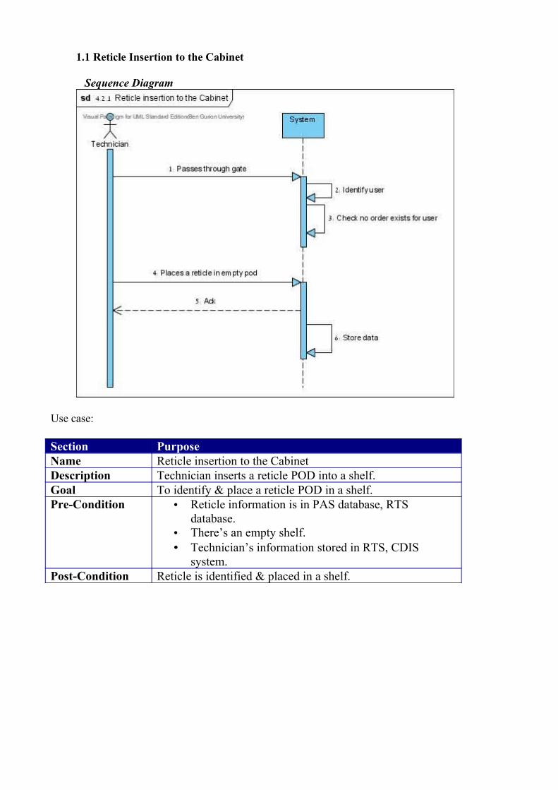
1.1 Reticle Insertion to the Cabinet
Sequence Diagram
Use case:
Section PurposeName Reticle insertion to the CabinetDescription Technician inserts a reticle POD into a shelf.Goal To identify & place a reticle POD in a shelf.Pre-Condition • Reticle information is in PAS database, RTS
database.• There’s an empty shelf.• Technician’s information stored in RTS, CDIS
system.Post-Condition Reticle is identified & placed in a shelf.
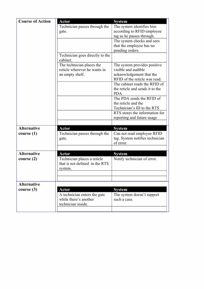
Course of Action Actor SystemTechnician passes through the gate.
The system identifies him according to RFID employee tag as he passes through.The system checks and sees that the employee has no pending orders.
Technician goes directly to the cabinet.The technician places the reticle wherever he wants in an empty shelf.
The system provides positive visible and audible acknowledgement that the RFID of the reticle was read.The cabinet reads the RFID of the reticle and sends it to the PDAThe PDA sends the RFID of the reticle and the Technician’s ID to the RTSRTS stores the information for reporting and future usage
Alternative course (1)
Actor SystemTechnician passes through the gate.
Can not read employee RFID tag. System notifies technician of error.
Alternative course (2)
Actor SystemTechnician places a reticle that is not defined in the RTS system.
Notify technician of error.
Alternative course (3) Actor System
A technician enters the gate while there’s another technician inside.
The system doesn’t support such a case.
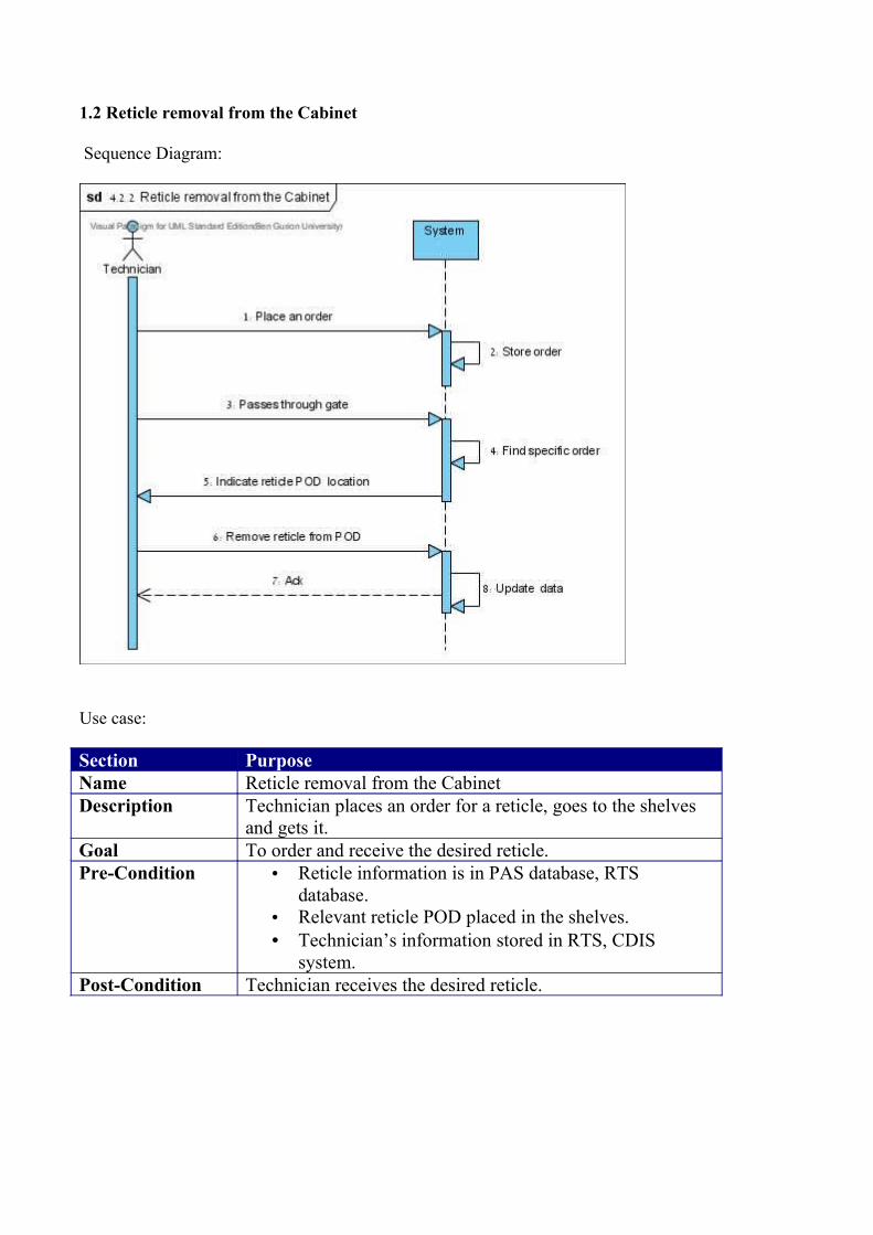
1.2 Reticle removal from the Cabinet
Sequence Diagram:
Use case:
Section PurposeName Reticle removal from the CabinetDescription Technician places an order for a reticle, goes to the shelves
and gets it. Goal To order and receive the desired reticle.Pre-Condition • Reticle information is in PAS database, RTS
database.• Relevant reticle POD placed in the shelves. • Technician’s information stored in RTS, CDIS
system.Post-Condition Technician receives the desired reticle.

Course of Action Actor SystemTechnician places an order for a certain reticle via the MTUI system.
The order is recorded in the RTS system.
Technician goes to the cabinet and passes through the gate.
The system reads the RFID tag of the employee.The system verifies there is an order associated with the employee ID.The system locates the reticle that was ordered.Green LED turns on; Cabinet beeps, indicating the POD location of the reticle.
Technician turns to the shelf with the green LED on, and removes the reticle POD from that shelf.
The cabinet beeps again.
Information regarding the removal will be sent to the PDA and from there to the Control System.
Alternative course (1)
Actor SystemTechnician passes through the gate.
Can not read employee RFID tag. System notifies technician of error.
Alternative course (2)
Actor SystemTechnician removes a reticle POD from the wrong shelf
System warns technician of error.
Alternative course (3)
Actor SystemTechnician that didn’t place an order goes through the gate
System assumes that employee came to take a reticle and therefore does nothing.
Alternative course (4)
Actor SystemA technician enters the gate while there’s another technician inside.
The system doesn’t support such a case.

1.3 Update reticle data in the system
Sequence Diagram:
Use case:
Section PurposeName Update reticle data in the system.Description System Operator needs to define a new reticle in the system,
or update data for existing reticle. Goal To update data regarding a certain reticle.Pre-Condition • Reticle information is in RTS database. If the update
is for an existing reticle then data is in PAS database as well.
• RFID tag is attached to the Reticle POD.Post-Condition Reticle information is updated.
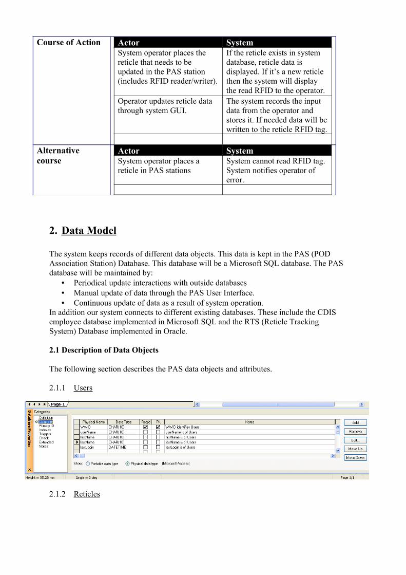
Course of Action Actor SystemSystem operator places the reticle that needs to be updated in the PAS station (includes RFID reader/writer).
If the reticle exists in system database, reticle data is displayed. If it’s a new reticle then the system will display the read RFID to the operator.
Operator updates reticle data through system GUI.
The system records the input data from the operator and stores it. If needed data will be written to the reticle RFID tag.
Alternative course
Actor SystemSystem operator places a reticle in PAS stations
System cannot read RFID tag. System notifies operator of error.
2. Data Model
The system keeps records of different data objects. This data is kept in the PAS (POD Association Station) Database. This database will be a Microsoft SQL database. The PAS database will be maintained by:
• Periodical update interactions with outside databases• Manual update of data through the PAS User Interface. • Continuous update of data as a result of system operation.
In addition our system connects to different existing databases. These include the CDIS employee database implemented in Microsoft SQL and the RTS (Reticle Tracking System) Database implemented in Oracle.
2.1 Description of Data Objects
The following section describes the PAS data objects and attributes.
2.1.1 Users
2.1.2 Reticles

2.1.3 Transactions
2.1.4 RFID Tags
2.1.5 Transaction Types


2.2 Database Objects Relationships and ERD
The PAS database will be a Microsoft SQL database. The following diagram shows the data objects relationships and the database ERD.

3. Behavioral Analysis
In this section we describe the control flow of our system. This includes the behavior of
the system, the flow of the main operations in our system, and the interaction between the
important classes. For the description we use the UML notation, and specifically
Sequence Diagrams and State Charts. In addition we describe main events that dictate the
behavior of the system.
3.1 Sequence Diagrams
The following Sequence Diagrams show the system behavior for each Use Case described
in section one.
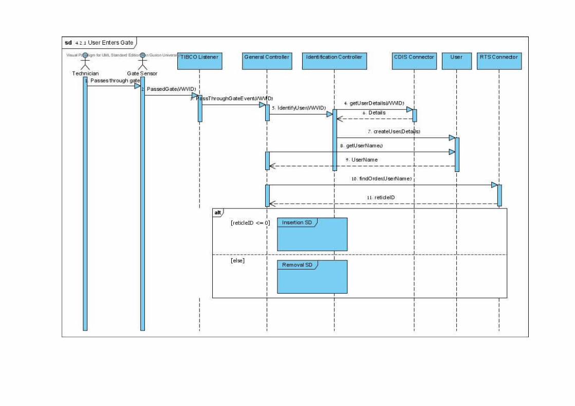
3.1.1 User Enters Gate Sequence Diagram
The first Sequence Diagram is common for both Reticle Insertion and Reticle
Removal Use Cases. This sequence diagram depicts the system’s behavior when a
technician walks through the gate. The gate RFID sensor senses that a technician is
passing. The RFID reader placed on the gate reads the technician’s ID, and passes it
to Control System through the TIBCO Listener. This listener listens for events passed
from the 3rd party PDA and passes them to the Control System. Its purpose is to
constantly listen to events transferred from the PDA. The TIBCO listener passes the
event information to the General Controller. This controller performs common
behavior for Reticle Insertion, and Reticle Removal. It relays information from the 3rd
party hardware (usually through the TIBCO listener and TIBCO connector) to the
specific controller relevant to that event. It then passes the employee ID to the
Identification Controller which in turn queries the CDIS employee database via the
CDIS connector. After the Identification controller receives the employee information
it creates a "User" instance. Then the General Controller queries the User to receive
relevant user information. This information is passed to the RTS connector, to find
out if the specific user has a pending order.
If the technician has a pending order, then the Reticle Removal Sequence is initiated.
Otherwise, the Reticle Insertion Sequence is initiated.
3.1.2 Reticle Removal Sequence Diagram
This system behavior occurs after a technician places an order through the MTUI System.
The order is stored in the RTS system. The technician enters the gate and the system
determines that the technician placed an order, as described in User Enters Gate Sequence
Diagram above. After the General Controller determines that the user has an order, it calls
the Removal Controller with Reticle ID information. This controller sends the Reticle
information to the TIBCO connector which functions as a mediator between the 3rd party
PDA and the Control System. The Reticle information is then transferred to the shelves
hardware through the PDA which in turn indicates to the technician where the desired
Reticle is located. This is done by using the LED indicator placed on each shelf. After the
technician removes the desired Reticle, the shelves placement sensor relays this
information to the General Controller through the TIBCO listener. The General Controller
notifies the Removal Controller of the change, which in turn updates the RTS and PAS
databases, through the appropriate connector classes.


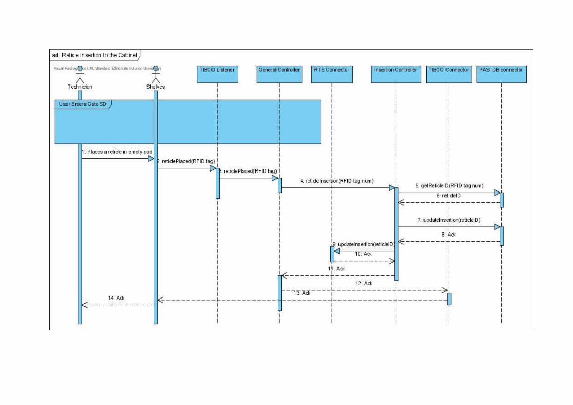
3.1.3 Reticle Insertion Sequence Diagram
This Sequence occurs after the technician passes the gate, and the system determines that
the technician did not place an order, as described above in User Enters Gate Sequence
Diagram. The technician places the returned Reticle in an empty shelf. The shelf
placement sensor senses this, reads the Reticle RFID tag number by using the shelf RFID
reader, and relays this information to the General Controller through the TIBCO Listener.
The General Controller sends this information to the Reticle Insertion Controller. The
RFID tag number is sent to the PAS database, through the PAS connector, to receive the
Reticle ID. After the Insertion Controller receives the Reticle ID it updates the PAS
database and the RTS database regarding the insertion event and the Reticle location. This
is done again via the appropriate controllers. An acknowledgment is sent to the technician
through the General Controller and the TIBCO connector.
3.1.4 Manual Reticle Information Update Sequence Diagram
This sequence is initiated when a System Operator places a Reticle in the PAS Station.
The RFID reader reads the Reticle RFID tag and relays this information to the PAS
controller. The PAS controller queries the PAS database through the PAS database
connector to receive Reticle information. This information is then transferred from the
PAS controller to the PAS Graphical User Interface, which displays the information to the
System operator. The system Operator can then update Reticle information through the
GUI. If this is done, the GUI passes the information to the PAS controller which in turn
updates the PAS database through the PAS connector.

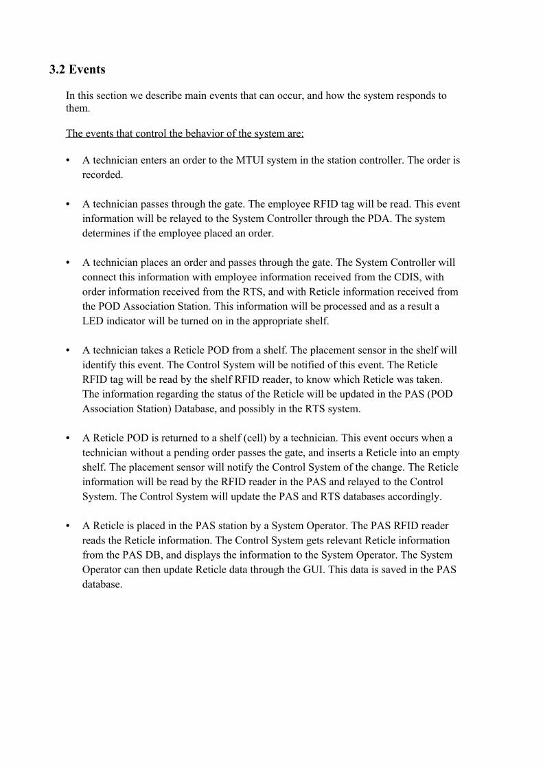
3.2 Events
In this section we describe main events that can occur, and how the system responds to them.
The events that control the behavior of the system are:
• A technician enters an order to the MTUI system in the station controller. The order is recorded.
• A technician passes through the gate. The employee RFID tag will be read. This event information will be relayed to the System Controller through the PDA. The system determines if the employee placed an order.
• A technician places an order and passes through the gate. The System Controller will connect this information with employee information received from the CDIS, with order information received from the RTS, and with Reticle information received from the POD Association Station. This information will be processed and as a result a LED indicator will be turned on in the appropriate shelf.
• A technician takes a Reticle POD from a shelf. The placement sensor in the shelf will identify this event. The Control System will be notified of this event. The Reticle RFID tag will be read by the shelf RFID reader, to know which Reticle was taken. The information regarding the status of the Reticle will be updated in the PAS (POD Association Station) Database, and possibly in the RTS system.
• A Reticle POD is returned to a shelf (cell) by a technician. This event occurs when a technician without a pending order passes the gate, and inserts a Reticle into an empty shelf. The placement sensor will notify the Control System of the change. The Reticle information will be read by the RFID reader in the PAS and relayed to the Control System. The Control System will update the PAS and RTS databases accordingly.
• A Reticle is placed in the PAS station by a System Operator. The PAS RFID reader reads the Reticle information. The Control System gets relevant Reticle information from the PAS DB, and displays the information to the System Operator. The System Operator can then update Reticle data through the GUI. This data is saved in the PAS database.

3.3 State Diagram
The system can be in a number of states according to the received sequence of events. This is depicted in the following State Diagram.
4. Object Oriented Analysis
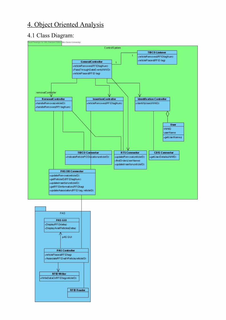
4.1 Class Diagram:

4.2 Class Description
More detailed description for the main classes described in the Class Diagram:
4.2.1 TIBCO_Listener:
Description: TIBCO protocol is a broadcast protocol, therefore a listener is needed in order to capture its messages. The responsibility of the TIBCO Listener class is to listen to the communication passing from the PDA through TIBCO protocol. When a message received the listener will identify it and forward the message to the GeneralController class for further use. There are 3 types of messages that can be transferred: Employee passing through the gate, reticle removal and reticle placed.
Main Methods: reticleRemoved(RFIDtagNum)
Pre-condition: Port is open for transmission of messages, network connection exists between PDA and Control System hardware, technician passed the gate and identified, order exists for this technician, and technician removes indicated Reticle. Post-condition: TIBCO Listener receives Reticle removed message with RFID tag number and relays this message to the General Controller.Usage: This function is used in the Reticle Removal Use Case.
PassedGate(WWID)Pre-condition: Port is open for transmission of messages, network connection exists between PDA and Control System hardware, and technician passes gate. Post-condition: TIBCO Listener receives passed gate message with employee identification number and relays this message to the General Controller.Usage: This function is used in the Reticle Removal and Reticle Insertion Use Cases.
ReticlePlaced(RFIDtagNum)Pre-condition: Port is open for transmission of messages, network connection exists between PDA and Control System hardware, technician passed the gate and identified, order does not exist for this technician, and technician places a Reticle in an empty shelf. Post-condition: TIBCO Listener receives Reticle placed message with Reticle RFID tag number and relays this message to the General Controller.Usage: This function is used in the Reticle Insertion Use Case.
4.2.2 General Controller:
Description: The General Controller is responsible for receiving information from the 3rd party hardware, through the TIBCO listener and passing this information to the specific controller responsible for the use case. In addition the General Controller class sends information from the Control System to the 3rd party Hardware through the TIBCO Connector.
Main Methods: ReticlePlaced(RFIDtagNum)
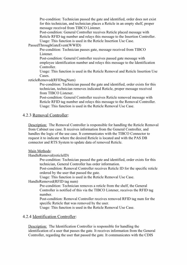
Pre-condition: Technician passed the gate and identified, order does not exist for this technician, and technician places a Reticle in an empty shelf, proper message received from TIBCO Listener. Post-condition: General Controller receives Reticle placed message with Reticle RFID tag number and relays this message to the Insertion Controller.Usage: This function is used in the Reticle Insertion Use Case.
PassedThroughGateEvent(WWID)Pre-condition: Technician passes gate, message received from TIBCO Listener. Post-condition: General Controller receives passed gate message with employee identification number and relays this message to the Identification Controller.Usage: This function is used in the Reticle Removal and Reticle Insertion Use Cases.
reticleRemoved(RFIDtagNum)Pre-condition: Technician passed the gate and identified, order exists for this technician, technician removes indicated Reticle, proper message received from TIBCO Listener. Post-condition: General Controller receives Reticle removed message with Reticle RFID tag number and relays this message to the Removal Controller.Usage: This function is used in the Reticle Removal Use Case.
4.2.3 Removal Controller:
Description: The Removal Controller is responsible for handling the Reticle Removal from Cabinet use case. It receives information from the General Controller, and handles the logic of the use case. It communicates with the TIBCO Connector to request it to indicate where the desired Reticle is located and with the PAS DB connector and RTS System to update data of removed Reticle.
Main Methods: HandleRemoval(reticleID)
Pre-condition: Technician passed the gate and identified, order exists for this technician, General Controller has order information. Post-condition: Removal Controller receives Reticle ID for the specific reticle ordered by the user that passed the gate. Usage: This function is used in the Reticle Removal Use Case.
HandleRemoved(RFID tag num)Pre-condition: Technician removes a reticle from the shelf, the General Controller is notified of this via the TIBCO Listener, receives the RFID tag number.Post-condition: Removal Controller receives removed RFID tag num for the specific Reticle that was removed by the user. Usage: This function is used in the Reticle Removal Use Case.
4.2.4 Identification Controller:
Description: The Identification Controller is responsible for handling the identification of a user that passes the gate. It receives information from the General Controller, regarding the user that passed the gate. It communicates with the CDIS

Connector to receive data regarding the user. This class is used in both the Reticle Insertion and Reticle Removal use cases.
Main Methods: IdentifyUser(WWID)
Pre-condition: Technician passed the gate, his WWID number is read from the RFID tag.Post-condition: Identification Controller receives the WWID number for the user that passed the gate. Usage: This function is used in the Reticle Removal and Reticle Insertion Use Cases.
4.2.5 Insertion Controller:
Description: The Insertion Controller is responsible for handling the Reticle Insertion from Cabinet use case. It receives information from the General Controller, specifically the RFID tag num of the inserted Reticle. It then queries the PAS DB through the PAS DB Connector about the reticle’s ID. This information is used to update both PAS DB and RTS system of reticle insertion.
Main Methods: ReticleInsertion(RFID tag num)
Pre-condition: Technician puts a reticle in the shelf, the General Controller is notified of this via the TIBCO Listener, receives the RFID tag number.Post-condition: Removal Controller receives inserted RFID tag num for the specific Reticle that was inserted by the user. Usage: This function is used in the Reticle Insertion Use Case.
4.2.6 PAS Controller:
Description: The PAS Controller is responsible for handling update of Reticle data in the system. When a reticle is placed in the PAS it receives the Reticle RFID tag number from the RFID reader. It then queries the PAS DB, through the PAS DB Connector about this Reticle. The received information is passed to the GUI and displayed to the user. Additionally, if a user enters reticle data through the GUI this data is relayed to the PAS Controller which updates this information in the PAS DB, again through the PAS DB Connector. This controller is used in the Update reticle data use case. Main Methods: ReticlePlaced(RFID tag)
Pre-condition: User places reticle POD in PAS, reticle RFID tag read by RFID reader.Post-condition: PAS Controller receives the RFID tag for the reticle that was placed in the PAS.Usage: This function is used in the Update reticle data use case.
AssociateRFIDwithReticle(ReticleID)Pre-condition: User places reticle in PAS, reticle RFID tag read by RFID reader, user inserts reticle data into GUI.Post-condition: PAS Controller receives the Reticle ID entered by the user through the GUI. Usage: This function is used in the Update reticle data use case.

4.3 Packages
The system consists of two packages. The first is the ControlSystem Package. This is the
main package. It includes the General Controller which interacts with the different use case
controllers, the database connectors, the TIBCO Listener and connector, and the User class.
This package is connected to the world outside our system through the TIBCO Listener and
through the different connectors: TIBCO, RTS, CDIS, and PAS DB connectors. The database
connectors represent the different databases to the ControlSystem.
The second package is The PAS (POD Association Station) package. It includes the PAS
GUI, PAS controller, PAS Reader and PAS writer. The PAS is responsible for storing
information regarding Reticles and their RFID tags. It allows the functionality of updating
Reticle data. The package is connected to the ControlSystem package through the connection
between the PAS Controller and the PAS DB Connector class. The package is connected to
the outside world via the RFID Reader Class which represents the physical RFID reader. This
reader senses when a Reticle is placed under it, read the tag, and relays this information to the
RFID reader class which in turn transfers this information to the PAS Controller.
4.4 Unit Testing
4.4.1 TIBCO_Listener Class
Testing for reticleRemoved(RFIDtagNum) method:
Testing for PassedGate(WWID) method:
Expected ResultDataActionThe RFID tag number
message is received and transferred to the General
Controller class.
A legal RFID tag number reticleRemoved(RFIDtagNum)
No message is transferred.Illegal RFID tag number
Expected ResultDataActionThe WWID number is
received and transferred to the General Controller
class.
A legal WWID numberPassedGate(WWID)
No message is transferred.
Illegal WWID number
Testing for ReticlePlaced(RFIDtagNum) method:
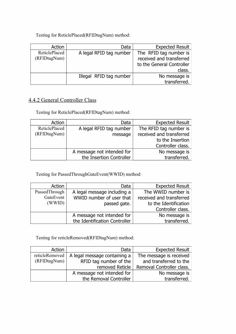
4.4.2 General Controller Class
Testing for ReticlePlaced(RFIDtagNum) method:
Testing for PassedThroughGateEvent(WWID) method:
Testing for reticleRemoved(RFIDtagNum) method:
Expected ResultDataActionThe RFID tag number is received and transferred to the General Controller
class.
A legal RFID tag numberReticlePlaced(RFIDtagNum)
No message is transferred.
Illegal RFID tag number
Expected ResultDataActionThe RFID tag number is received and transferred
to the Insertion Controller class.
A legal RFID tag number message
ReticlePlaced(RFIDtagNum)
No message is transferred.
A message not intended for the Insertion Controller
Expected ResultDataActionThe WWID number is
received and transferred to the Identification
Controller class.
A legal message including a WWID number of user that
passed gate.
PassedThroughGateEvent
(WWID)
No message is transferred.
A message not intended for the Identification Controller
Expected ResultDataActionThe message is received
and transferred to the Removal Controller class.
A legal message containing a RFID tag number of the
removed Reticle
reticleRemoved(RFIDtagNum)
No message is transferred.
A message not intended for the Removal Controller

4.4.3 Removal Controller Class
Testing for HandleRemoval(reticleID) method:
Testing for HandleRemoved(RFID tag num) method:
4.4.4 Identification Controller Class
Testing for IdentifyUser(WWID) method:
4.4.5 Insertion Controller Class
Testing for ReticleInsertion(RFID tag num) method:
Expected ResultDataActionThe message is received
and transferred to the TIBCO Connector.
A legal message containing a Reticle ID number of the Reticle that was ordered
HandleRemoval(reticleID)
No message is transferred.
An illegal message.
Expected ResultDataActionThe message is received
and relevant data is updated in PAS DB and
RTS via the PAS DB connector and RTS
system.
A legal message containing a Reticle RFID number of the
Reticle that was removed
HandleRemoved(RFID
tag num)
Expected ResultDataActionThe message is received
and the Identification Controller queries CDIS
DB for specific user data. This is done through the
CDIS DB Connector.
A legal message containing the WWID of the user that passed the gate. Received
from the General Controller.
IdentifyUser(WWID)
No message is transferred.
A message other then the above message.
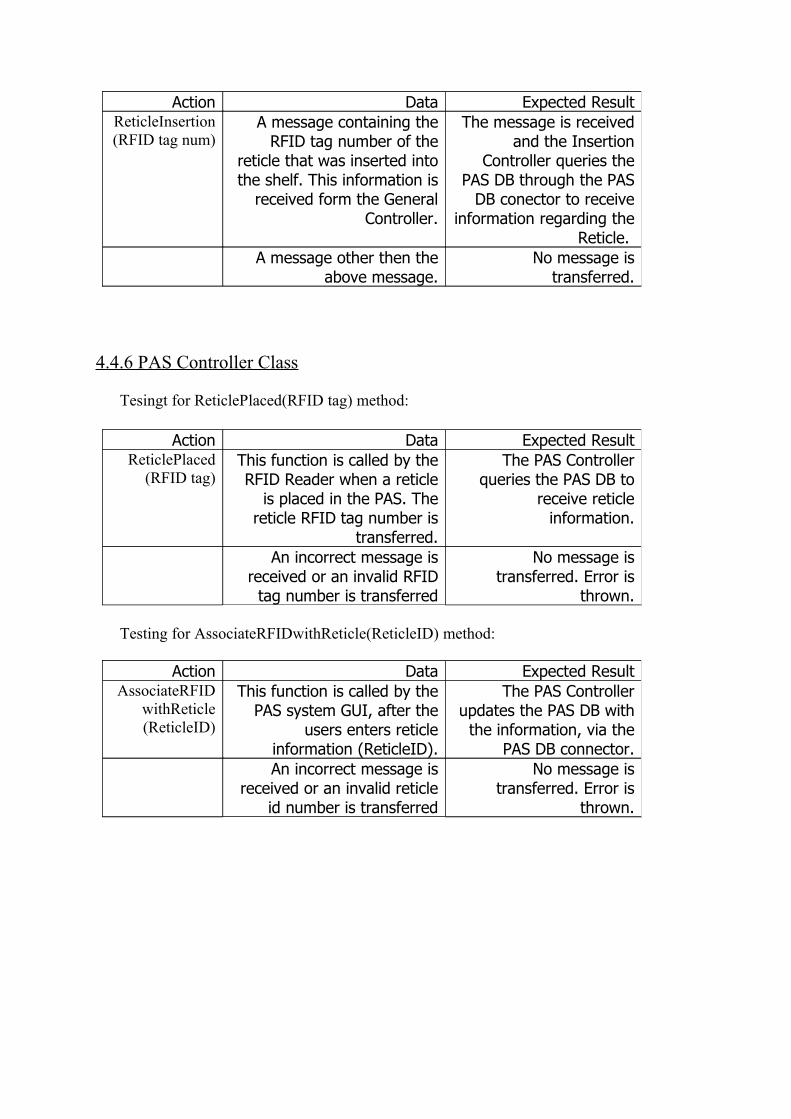
4.4.6 PAS Controller Class
Tesingt for ReticlePlaced(RFID tag) method:
Testing for AssociateRFIDwithReticle(ReticleID) method:
Expected ResultDataActionThe message is received
and the Insertion Controller queries the
PAS DB through the PAS DB conector to receive
information regarding the Reticle.
A message containing the RFID tag number of the
reticle that was inserted into the shelf. This information is
received form the General Controller.
ReticleInsertion(RFID tag num)
No message is transferred.
A message other then the above message.
Expected ResultDataActionThe PAS Controller
queries the PAS DB to receive reticle
information.
This function is called by the RFID Reader when a reticle
is placed in the PAS. The reticle RFID tag number is
transferred.
ReticlePlaced(RFID tag)
No message is transferred. Error is
thrown.
An incorrect message is received or an invalid RFID
tag number is transferred
Expected ResultDataActionThe PAS Controller
updates the PAS DB with the information, via the
PAS DB connector.
This function is called by the PAS system GUI, after the
users enters reticle information (ReticleID).
AssociateRFIDwithReticle(ReticleID)
No message is transferred. Error is
thrown.
An incorrect message is received or an invalid reticle
id number is transferred

5. System Architecture
In the following figure a block diagram showing major components of the larger system are shown as well as the connections between them. Blue color represents existing components. Purple represents components that will be built from scratch. The third party solution includes the physical shelves, as well as the gate, and a PDA. The CDIS Employee DB is a general Intel Microsoft SQL-Server Database. It holds information regarding all employees in Intel. The Control System will interact with the CDIS by a Web Service that will retrieve data from the CDIS SQL database for updating the PAS database. The MTUI system is an interface for the technician in the clean room. The technicians use it to create orders for Reticles. The orders are then transferred to the Reticle Tracking System (RTS), which stores this Information in its WART Database. This database is implemented in Oracle. The Control System interacts with the RTS system through database queries and updates, using OLE DB standard. This is performed to receive information regarding orders and Reticles. Some of this information is used to update information in the PAS database, or to join this RTS and PAS data. The above components (RTS, WART, CDIS) each run on dedicated servers. Their location is transparent to the Control System and all the communication is done in the methods mentioned above. The Control System will be written in .NET (C#) using Visual Studio 2003, and will run on a Windows 2003 Server. Its exact architecture can be seen in section 4.1. The POD Association Station (PAS) application will be written in .NET as well, and will run on the same Windows 2003 Server as the Control System, while its Database will run on a Microsoft SQL-Server. The communication between the PAS and the Control System is explained in section 4.1. The 3rd party hardware includes a PDA that controls the Reticle Shelves and the Gate. The shelves include for each shelf (cell) a green and red LED indicator, a placement sensor, and a RFID reader. The gate includes a RFID reader. The communication between the gate and the PDA, as well as between the shelves and the PDA is done via the TIBCO protocol. The connection between the PDA and the Control System is done via TIBCO protocol as well. The communication will become feasible by using a TIBCO software (socket-like) component. The specific classes responsible for this connection in the Control System are the TIBCO Listener and TIBCO connector, as detailed in section 4 and 3. The PAS (POD Association Station) includes both a Microsoft-SQL database, as explained earlier, and a User Interface which is used for inserting and updating reticles and associating RFID tags with the reticle. The PAS communicates with an RFID reader and writer using the 2 classes: RFID Reader and RFID Writer as shown in section 4.1. The reader and writer classes use a serial communication port in order to receive or transmit information from the physical RFID reader or writer. The data is sent through the serial port using RS-232 protocol.

System Architecture Diagram:

6. User Interface Draft
6.1 Graphic User Interface for the POD Association Station (PAS):
6.1.1 Logon Screen
6.1.2 Administrator Page
The PAS GUI is used by the System Operator in order to create and update associations between RFID tags and Reticles. When a RFID tag is placed in the RFID reader, the reader reads its data and the tag ID is displayed to the user. (In the example screen below we can see that the RFID tag that was read has the ID “0F0296AF3C”). If the RFID tag that was read is already associated with a Reticle, then the reticle information is displayed on the left side of the screen (In our example there isn’t any Reticle associated with the RFID tag, therefore the Reticle Information fields are empty).If the system finds a Reticle associated with the RFID tag then the user can press on ‘De-Assign Tag from Reticle’ button in order to de-assign between them.
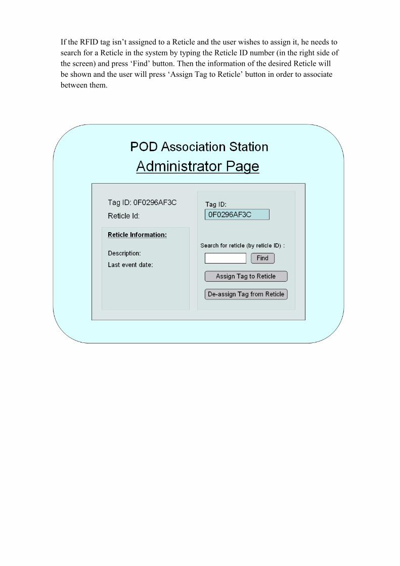
If the RFID tag isn’t assigned to a Reticle and the user wishes to assign it, he needs to search for a Reticle in the system by typing the Reticle ID number (in the right side of the screen) and press ‘Find’ button. Then the information of the desired Reticle will be shown and the user will press ‘Assign Tag to Reticle’ button in order to associate between them.

7. Testing
7.1 Functional Testing
Reticle insertion to the Cabinet
The testing of this scenario will include passing with an employee RFID tag through the gate and inserting a reticle POD (with RFID tag attached to it) to a shelf. Then we will check that the data regarding the specific reticle was updated in both RTS and PAS systems.
Reticle removal from the Cabinet
This scenario will be tested by first making an order for a reticle in the MTUI system. Then the employee RFID tag will be passed through the gate. A LED should indicate the successful reading of the RFID tag. We will then remove the reticle from the correct shelf and check if indeed the reticle is the one that was ordered. We will do that by reading the RFID tag number on the reticle POD and its ID number and compare this data to the data that is stored in the RTS system regarding the order.
Update reticle data in the system
We will test this scenario by placing a reticle RFID in the PAS. We will check that the information displayed in the GUI of the PAS is indeed the information of the specific reticle. Then we will update some of the reticle information through the PAS GUI, and check that this information is updated in the PAS DB. Additionally we will verify that the reticle ID is written to the RFID tag attached to the reticle, through the RFID writer.
7.2 Non Functional Testing
7.2.1 Speed, Capacity & Throughput:
• Technician identification process at the gate will take up to 2 seconds – The test will include measuring time for this process.
• In 95% of the cases, the system will succeed in reading & identifying the employee passing through the gate. In the rest of the cases the system will indicate the identification failure – In order to test this requirement a large number of real employee RFID tags will be passed through the gate. For each reading shown as successful we will check that the RFID information was successfully read by comparing the actual RFID tag and the RFID tag number received by the General Controller from the TIBCO listener. In addition, we will check that the number of unsuccessful readings does not exceed 5% of the total readings.
• If a technician removes a wrong reticle (different than the one ordered), the system will indicate wrong action within 2 seconds. This will be tested by making

an order for a reticle, entering the gate, and removing a different reticle then the one ordered (which the system indicates with the LED). We will verify that the system indicates of the error within 2 seconds.
7.2.2 Availability:
• Before the system will be operational it will be used by a test team. During this period we will record and examine the time that the system is down. We will verify that the system is up 98% of the time.


