Embed Size (px)
Citation preview

Robotics and Computer-Integrated Manufacturing 42 (2016) 17–38
Contents lists available at ScienceDirect
Robotics and Computer-Integrated Manufacturing
http://d0736-58
n CorrE-m
skgupta
journal homepage: www.elsevier.com/locate/rcim
Addressing perception uncertainty induced failure modes in roboticbin-picking
Krishnanand N. Kaipa a, Akshaya S. Kankanhalli-Nagendra a, Nithyananda B. Kumbla a,Shaurya Shriyam a, Srudeep Somnaath Thevendria-Karthic a, Jeremy A. Marvel b,Satyandra K. Gupta c,n
a Maryland Robotics Center, University of Maryland, MD, USAb National Institute of Standards and Technology, Gaithersburg, MD, USAc Center for Advanced Manufacturing, University of Southern California, CA, USA
a r t i c l e i n f o
Article history:Received 14 November 2015Received in revised form6 April 2016Accepted 3 May 2016Available online 14 May 2016
x.doi.org/10.1016/j.rcim.2016.05.00245/& 2016 Elsevier Ltd. All rights reserved.
esponding author.ail addresses: [email protected] (J.A. [email protected] (S.K. Gupta).
a b s t r a c t
We present a comprehensive approach to handle perception uncertainty to reduce failure rates in roboticbin-picking. Our focus is on mixed-bins. We identify the main failure modes at various stages of the bin-picking task and present methods to recover from them. If uncertainty in part detection leads to per-ception failure, then human intervention is invoked. Our approach estimates the confidence in the partmatch provided by an automated perception system, which is used to detect perception failures. Humanintervention is also invoked if uncertainty in estimated part location and orientation leads to a singu-lation planning failure. We have developed a user interface that enables remote human interventionswhen necessary. Finally, if uncertainty in part posture in the gripper leads to failure in placing the partwith the desired accuracy, sensor-less fine-positioning moves are used to correct the final placementerrors. We have developed a fine-positioning planner with a suite of fine-motion strategies that offerdifferent tradeoffs between completion time and postural accuracy at the destination. We report ourobservations from system characterization experiments with a dual-armed Baxter robot, equipped with aEnsenso three-dimensional camera, to perform bin-picking on mixed-bins.
& 2016 Elsevier Ltd. All rights reserved.
1. Introduction
Bin-picking is a precursor to kitting [1,2] and assembly opera-tions in many discrete-part manufacturing applications [3–5]. Theuse of robots for bin picking can enable handling a wide variety ofparts without any change in the hardware; hence it offers a flex-ible automation solution. Machine vision is a key enabling tech-nology in this context [6,7]. Robotic bin-picking, guided by visionand other sensor modalities, has been successfully demonstratedwith a high degree of reliability for bins containing a single type ofpart with a relatively simple shape [8].
When bins are complex, the reliability of robotic bin pickingoperations is reduced. The complexity in bins might arise due tothe presence of multiple different types of parts. Such bins arecalled mixed bins. Recognizing the desired part in a mixed binand estimating its location is a much more challenging problemfrom the perception point of view. Unstructured, randomly dis-tributed, mixed-bins make the perception problem challenging
rvel),
due to the following reasons: (1) parts may lie in widely differentthree dimensional (3D) postures and (2) parts may be eitherpartially or completely occluded by other parts. The problem iscompounded due to factors such as sensor noise, backgroundclutter, shadows, complex reflectance properties, and poorlighting conditions.
The complexity of the bin might also increase because the partspresent in the bin have complex shapes, and can only be removedby holding them at certain locations and moving them in certaindirections. Uncertainty in part location and orientation estimatesmay lead to a failure when the robot tries to extract the part fromthe bin. The potential for part tangling, and occlusion of graspingsurfaces, makes the planning problem challenging because ofperception uncertainties.
The effect of perception uncertainty propagates through everystage of task execution including, part recognition and pose esti-mation, singulation, and positioning. This thereby impacts theoverall system performance. For example, the detected part matchmay not correspond to the specified part. Uncertainty in pose es-timation may lead to poor singulation plans, and thereby singu-lation failures. Finally, uncertainty in the initial grasped posture ofthe part may lead to errors in part posture at the destination after

Fig. 1. Flowchart showing how uncertainty is handled at various stages of the bin-picking task.
K.N. Kaipa et al. / Robotics and Computer-Integrated Manufacturing 42 (2016) 17–3818
final drop off. However, many manufacturing applications requireparts to be placed in a specified posture, within tight tolerances,before tasks like assembly or packaging can take place [9].
To improve the reliability of the bin-picking operations, weneed to characterize the effect of perception uncertainty on bin-picking task execution performance. We also need to developmethods to deal with situations when high perception uncertaintyrequires specialized methods to prevent the failure. In this paper,we present a comprehensive approach to handle perception un-certainty to reduce failure rates in unstructured robotic bin-pick-ing. The main failure modes at various stages of the bin-pickingtask and methods to recover from them are shown in Fig. 1. Wefirst characterize the uncertainty in estimating the six dimensional(6D) posture of a part match found by using an automated per-ception system. The input to the system is a CAD model of the partto be singulated and a 3D point cloud of the mixed-bin. The re-sulting uncertainty information is used to estimate confidence inpart recognition and pose estimation. If perception uncertaintyresults in a part detection failure or singulation planning failure,then human intervention is invoked. We have developed a userinterface that enables remote human interventions when neces-sary. Intervention in this context may correspond to the humanfinding a good part match and obtaining an improved estimate ofthe part pose by using appropriate controls present in the userinterface. If perception uncertainty results in an unacceptable er-ror in the final posture of the part at the destination, then finepositioning is invoked to achieve the desired postural accuracy.We have developed a fine-positioning planner to correct errors inthe destination posture of the part arising due to uncertainty inthe initial grasped state. We have developed a suite of fine-motionstrategies that offer different tradeoffs between completion timeand postural accuracy at the destination.
In our earlier works, we presented preliminary versions ofautomated perception algorithm [10], perception failure resolutionusing human intervention [11], singulation planning [12], and fine-positioning [13]. We treated each problem in an isolated manner.This paper significantly improves upon methods reported in ourprevious works and presents a comprehensive approach to iden-tify and address perception-uncertainty-induced failure modes inrobotic unstructured bin-picking.
2. Related work
Many research groups have addressed the problem of roboticbin-picking. Different aspects of robotic bin-picking include per-ception, grasp-planning, and motion planning. Each of these re-presents a vast area of research in itself. Therefore, we survey onlyprior research that integrated these aspects to achieve bin-pickingor grasping. A summary of the focus of various works on bin-picking is shown in Table 1. In our survey, we also pay attention towhether uncertainty was taken into account, and if so, how it washandled at different stages of task execution. Most of the researchin bin-picking considered the problem up to stage where the partis successfully picked from the bin, while ignoring the next stageof delivering the part in a known posture accurately at the desti-nation. We survey the field of sensorless manipulation where thisproblem was treated separately.
2.1. Perception for robotic bin-picking
Most previous attempts on a systems approach to bin-pickingmainly focussed on the perception problem[25,24,23,21,4,20,19,18,16,15,14], while assuming accurate robotgrasping. However, model inaccuracies and sensor uncertaintiesmake it difficult for a majority of the perception algorithms toprovide reliable object recognition and localization estimates,thereby affecting overall bin-picking performance.
Except for a few, many of these methods ignored the evaluationof perception quality before proceeding to picking the part. Liuet al. [4] presented a directional, chamfer-matching-based, objectlocalization and pose estimation in heavy clutter for robotic binpicking. The accuracy of their method was tested empirically byevaluating the consistency of a pose estimate across multipleviewpoints of the camera. This was achieved by placing an objectin the scene, estimating its pose in local frames of different cameraviewpoints, transforming them into the world frame, and plottingthe histogram of deviations from the median pose estimate in 6D.But there was no mechanism in place to rate the perception resultduring task execution.
Papazov et al. [33] presented a 3D object-recognition and pose-estimation approach for grasping, based on geometric descriptors,hashing techniques, and random-sampling consensus (RANSAC)-like sampling strategies. The authors evaluated the quality of arecognition hypothesis by defining an acceptance function,

Table 1Summary of aspects addressed in various works on bin-picking.
Main focus Sensor Bins Parts Robot implementation
[14] Perception Sick Ranger and laser diode Mixed Plastic gears, rings, etc. No[15] Perception 3D depth sensor Homogeneous No[16,17] Perception Kinect Homogeneous Connector pipes Yes[18] Perception 2D monochrome camera Homogeneous 2D planar objects Yes[19] Perception 2D camera with multi-lighting Homogeneous Shiny brackets Yes[20] Perception Stereo camera Homogeneous Wheel hubs, brake disks, piston rods Yes[4] Perception Multi-flash camera Mixed Shiny metal parts, texture-less plastic
objectsYes
[21] Perception 3D camera Homogeneous Alternators No[22] Perception Laser scanner Homogeneous Joist hangers, plug gauges, piston rods Yes[23] Perception Laser ranging No[24] Perception Laser ranging and video imaging Mixed Gears, balls, wooden objects No[25] Perception Photometric stereo Homogeneous toroid shaped parts Yes[26] Grasp planning 3D camera Homogeneous Coil springs, metal linkages Yes[27] Grasp planning 3D camera Mixed piston rods, plastic toys Yes[28] Grasp planning 3D camera Homogeneous piston rods Yes[29] Motion planning 3D grid scanner Homogeneous Metal pipes Yes[30] Perception and grasp planning SICK IVP Ruler E1200 laser line
scannerHomogeneous piston rods Yes
[31] Perception and grasp planning solid state range camera Homogeneous Boxes Yes[32] Grasp and motion planning 3D camera Homogeneous Bananas Yes[33] Perception, grasp, motion planning 3D laser scanner Mixed cans, polyhedral shaped objects Yes[34] Systems approach, human robot
collaborationTime-of-flight camera Homogeneous Plastic pipes Yes
[35] Learning to improve grasping 3D camera Homogeneous Yes
K.N. Kaipa et al. / Robotics and Computer-Integrated Manufacturing 42 (2016) 17–38 19
comprising a visibility term and a penalty term. The visibility termwas computed as the ratio of transformed model points that fellwithin a certain threshold band of the scene to the total number ofthe model points. The penalty term penalized a hypothesis if itviolated the condition that a scene point lying behind the localizedmodel cannot be seen through an opaque surface when viewedfrom the perspective of the camera. The penalty was computed asa ratio of transformed model points, which are between the pro-jection center of the range image and a range-image pixel, to thetotal number of model points. The hypothesis was accepted if thevisibility term was greater than, and the penalty term was lesserthan, certain manually set thresholds. The authors addressed un-certainty by empirically testing how the recognition rate of theiralgorithm varied as a function of zero-mean Gaussian noise addedinto the noise-free, scene data.
Perception failures were not addressed explicitly in most of theabove approaches. The robotic bin-picking system developed byFuchs et al. [34] has built-in mechanisms to detect object-locali-zation failures. In particular, they assume significant uncertainty inobject pose estimation and initiate grasping only when the relia-bility of the pose hypothesis falls below a given threshold.Otherwise, the localization is restarted from a different view pointof the camera. Another relevant work is an algorithm, presentedby Pronobis and Caputo [36], which is able to measure its ownlevel of confidence in performing a visual, place-recognition task.Taking a support vector machine approach, the authors propose amethod for measuring the confidence level of the classificationoutput based on the distance of a test image and the averagedistance of training vectors.
2.2. Grasping under uncertainty
Grasp planning literature is very vast. Approaches can bebroadly divided into analytical and data-driven methods [37]. Areview of analytical approaches to grasp synthesis can be foundin [38]. A comprehensive survey on data-driven grasp synthesiscan be found in [39]. Data-driven approaches have become morepopular over the past decade with the advent of simulation-based tools like Graspit! [40]. Grasp evaluation is usually based
on a widely used, force-closure, quality metric for precisiongrips [41].
Given that pose-estimation error impacts grasping perfor-mance in practice, many researchers have addressed the problemof grasp planning under perception uncertainty [42–46] anduncertainty in object shape due to manufacturing tolerances, andmechanics, due to limits on sensing during grasping [47]. Nguyen[42] incorporated contact-location uncertainty into force-closureanalysis. Roa and Suarez [43] proposed a grasp-synthesis ap-proach that accounted for the fact that the real fingers can nevercontact the object at the computed points. Zheng and Qian [44]considered both friction uncertainty and position uncertainty intheir force-closure analysis. Each of these approaches consideredthe effects of contact location uncertainty independently, but didnot address the effects of calibration error and object pose un-certainty on grasp quality. Grasping under pose uncertainty wasaddressed in the works of Berenson et al. [45] and Weisz andAllen [46].
Kehoe et al. [47] considered uncertainty in object shape due tomanufacturing tolerances, and mechanics, due to limits on sensingduring grasping. Their algorithm takes three inputs: an approx-imate object outline, Gaussian uncertainty around each vertex, andcenter of mass. The grasp-quality metric was defined as a lowerbound on the probability of achieving force closure, and wascomputed using Monte Carlo sampling. Glover et al. [48] proposedprobabilistic models of object geometry for grasp planning. Baye-sian models have been used by Goldberg and Mason [49] andHsiao et al. [50] to address pose uncertainty in grasping.
Most approaches described above focus on grasping problemsthat involve interactions between the gripper and the single objectto be grasped. However, we are interested in the class of bin-picking problems where performance is measured as a compositeof (1) quality of approach toward the object, (2) grasp quality, and(3) quality of extraction of the grasped object. Dupius et al. [28]proposed a two-fingered, grasp-planning method in the context ofvision-guided robotic bin-picking. Off-line grasp candidates aregenerated for each instance of the object based on the qualitymetrics provided by the Graspit! simulator. Each candidate in-stance is evaluated online based on how many pre-generated

K.N. Kaipa et al. / Robotics and Computer-Integrated Manufacturing 42 (2016) 17–3820
grasps are collision-free with respect to neighboring objects. Theirapproach dealt with bins with the same type of parts.
2.3. Sensorless manipulation to reduce uncertainty in positioning
Sensorless manipulation approaches can be broadly dividedinto two categories based on whether part manipulation is in-duced by the robot through external surfaces, or achieved by therobot directly using non-prehensile manipulation moves. Erdmannand Mason [51] presented a robot motion planner that generatedtray-tilting plans to orient planar objects. In particular, a robottilted the tray containing the randomly oriented object causing theobject to slide into walls, along walls, and into corners, until theobject settled into a desired orientation. Erdmann et al. [52] ex-tended the tilting strategy to three-dimensional polyhedral parts.Akella et al. [53] used a combination of a controlled one degree-of-freedom joint and a constant-velocity conveyor belt to orientplanar parts.
In all the above approaches, the robot induced part motionsthrough an external surface rather than applying the forces di-rectly on the part. Later, non-prehensile manipulation methodswere proposed where the gripper fingers interacted with the partwithout encompassing it [54,55]. Goldberg [54] presented a sen-sorless manipulation method, in which a simple parallel-jawgripper applied forces on the part directly, resulting in its specifiedorientation in a finite sequence of steps. Similarly, Erdmann [55]presented a non-prehensile, two-palm, manipulation method fororientation of polyhedral objects. The entire palms were used ra-ther than the fingertips alone. Dogar and Srinivasa [56] used thenotion of task mechanics to introduce push-grasp plans for dex-terous hands in the presence of object-pose uncertainty and highclutter. However, this was presented as a grasping technique asopposed to post-grasp manipulation. Kristek and Shell [57] ex-tended the sensorless, non-prehensile manipulation to deformablepolygonal parts. Other recent examples of sensorless manipulationinclude [58,59], and [60].
1 Video link: https://www.youtube.com/watch?v¼ZfcCmijILsw2 DISCLAIMER: Any commercial product or company name in this paper is
given for informational purposes only. Their use does not imply recommendationor endorsement by NIST or the University of Maryland.
3. Problem formulation
3.1. Hybrid cell
Hybrid cells support different human–robot collaboration(HRC) modes [61–64]. State-of-the-art HRC approaches havemainly considered humans and robots physically sharing theworkspace inside the hybrid cell. Human and robot may beworking concurrently on a task, sequentially on the task, or one ofthem may perform most of the operations, while the other playsan assistive role. We take a different approach to achieving HRC inhybrid cells. We are mainly interested in a human-on-the-callmode that enables a remotely located human to take over whenthe robot needs help.
However, implementing this mode requires the robot to be cap-able of detecting an impending failure and invoking human inter-vention. Currently, robots have difficulty in assessing their owncapability to complete a task. Consider the following case. A robot iscapable of picking a part if the part is presented to it at a certainlocation. However, if the part has shifted from its nominal location,the robot might not be able to pick it. The robot does not simplyknowwhere the transition boundary between task-execution successand failure lies. As it attempts to pick the part, it might bump into it,push it further away, and jam the material handling system. This can,in turn, trigger a system fault and cause a shut-down of the system.
To use robots in small-production batch operations, they mustbe able to estimate the probability of task completion before be-ginning the task. This will enable robots to assess their confidence
in doing a task. If the robot does not have a high confidence incompleting a task, then it can call for help. This will enable humanoperators to provide the robot the needed assistance and preventmajor system faults that result from task-execution failures. Pro-viding such task assistance to robots is cheaper than recoveringfrom a system shutdown. We illustrate these concepts in thecontext of robotic bin-picking in this paper.
The experimental setup used (Fig. 2) consists of RoboSAM,1 aROBotic Smart Assistant for Manufacturing and a user interface thatallows remote human interventions. The RoboSAM system is builtusing a Baxter Research Robot2 and an Ensenso 3D camera. We aremainly interested in part-order problems that specify multiplequantities of different parts to be singulated from a bin of randomlyscattered parts and to be delivered in a known posture at a desti-nation location as rapidly as possible. An illustration of the singu-lation task is shown in Fig. 3. Successful singulation, given a noisyestimate of part posture, primarily depends on (1) planning theapproach of the gripper toward the part such that it does not collidewith other nearby parts, (2) determining grasp postures that resultin force-closure of the grasped part, and (3) performing tangle-freeextraction. Different singulation-failure scenarios are shown inFig. 4. We consider representative industrial parts that afford dif-ferent recognition and grasping complexities to illustrate variouschallenges encountered during the bin-picking task. Fig. 5 showsexamples of part placements in a bin with varying degrees of per-ception and singulation complexities. In this context, the quality ofthe point cloud is a function of the fraction of points on the surfaceof the part that are exposed to the camera, and thereby, get regis-tered in the point cloud. For example, in Fig. 5(a), the part to besingulated gives a good point cloud, since a large fraction of itssurface area is visible from the camera. However, in Fig. 5(b), thepart is in an orientation such that relatively few points get regis-tered, resulting in a poor quality of the point cloud. Finally, finepositioning is invoked if needed to achieve the desired posturalaccuracy. Fig. 6 illustrates the problem of fine-positioning.
3.2. Definitions
Definition 1. A general 6D posture is represented by α β γℓ ∈ = { }x y z, , , , ,6 where ( )x y z, , and α β γ( ), , represent the
position and orientation (in Euler angle representation), respec-tively in 3D.
Definition 2. A mixed-bin κ( { })n n, , i is a bin of randomly scat-tered pile of n parts, comprising multiple instances ni of κ differentpart types:
∑
κ κ( { }) = { = … = … }|
| = =( )
κ
( )
=
n n p j n i
n n
, , : 1, 2, , , 1, 2, ,
1
i ij
i
ii
1
where part ( )pij represents the jth instance of part type i.
Definition 3. Given a mixed-bin , we define a part-order( { ¯ })n, i as an order placed by a customer requesting a set of
parts ⊆ , while requiring each part ∈( )pij to be transferred
and positioned at a destination posture ℓ( )ij within an expected
postural accuracy Δℓ, where = … ¯ ≤ ∈j n n i1, 2, , ,i i , κ(| | ≤ )represents the set of indices of the part types to be selected.

Fig. 2. Hybrid Cell showing the RoboSAM system built using the Baxter robot and the Ensenso 3D camera and the remote human operator.
Fig. 3. Illustration of the singulation task: (a) Robot gripper in the initial approach posture. (b) Part grasped. (c) Part successfully singulated.
K.N. Kaipa et al. / Robotics and Computer-Integrated Manufacturing 42 (2016) 17–38 21
Definition 4. A sequenced-order is defined as a part-order thatrequires the parts to be delivered in a specified sequence.
Definition 5. Singulation is defined as the concatenation of fourstages including positioning the gripper at an appropriate postureabove the bin, approaching the gripper toward the part, graspingthe part, and extracting the part out of the bin.
Definition 6. We define tangle-free-singulation as a singulation ofa part from a bin such that it is not tangled with other neighboringparts in the bin during extraction, thereby ensuring singulation ofonly one part at a time (Fig. 3).
Definition 7. Fine-positioning refers to the act of applying appro-priate sliding forces on the part until its posture is within thedesired accuracy limits.
3.3. High-level decision making in the hybrid cell
Given a mixed bin κ( { })n n, , i and a sequenced part-order( { ¯ })n, i , our goals in this paper are to achieve tangle-free sin-
gulation of the first part ∈p in the sequence and to position thatpart at a destination posture within a specified postural accuracyΔℓ. The inputs to the system are a CAD model of the part pd to besingulated and a 3D point cloud of the mixed-bin .
The steps in the high-level planner are given below:
1. Characterize the uncertainty in estimating the 6D posture of apart instance ( )p j that is detected by using an automated
perception system (Section 4), while reporting the following:
• Estimate of part posture ℓ̂( )j
with postural uncertainty σ( )j .• Confidence in the part match by using a signature basedmethod (Section 4.2).
2. If confidence is acceptable, then• Perform singulation planning (Section 5) to generate andevaluate singulation plans, while accounting for
○ Uncertainty in the estimated part pose σ( )j .○ Grasp-approach quality qa.○ Grasp quality based on force-closure qg.○ Part being tangle-free during singulation.• If a singulation plan exists (for given σ( )j ), then○ Execute the singulation plan.○ Proceed to fine-positioning if needed (Section 6): Given σ( )j
and Δℓ, select a fine-positioning strategy.
else-if σ( )j is low (plan fails as the part is in a difficult-to-reachposture)○ Randomize-bin and restart perception characterization
else Initiate human intervention (Section 7) to detect part withhigh confidence
• If match found, then proceed with singulation planningelse Send Randomize-bin command to robot
else Initiate human intervention (Section 7) to reduce σ( )j
• If match found, then proceed with singulation planningelse Send Randomize-bin command to robot

Fig. 4. Different failure scenarios during singulation of a desired part from the bin: (a) Failure during the approach phase. The two striped circles represent the relativepositions of the two fingers with respect to the part to be grasped during approach. (b) Failure during the grasping phase. (c) Failure during the extraction phase. (d) Failureas a result of the part being tangled with another part.
K.N. Kaipa et al. / Robotics and Computer-Integrated Manufacturing 42 (2016) 17–3822
A flow chart of the high-level planner is shown in Fig. 7.
4. Confidence estimation in perception
Given a mixed bin κ( { })n n, , i and a desired part pd to besingulated, the first step in the high-level decision making in thehybrid cell (Section 3.3) is to characterize the uncertainty in esti-mating the 6D posture of a part instance ( )p j . This part instance isdetected by using an automated perception system, while re-
porting pose estimate ℓ̂( )j
with postural uncertainty σ( )j .
4.1. Automated perception algorithm
Given a CAD model of the desired part to be singulated and the3D point cloud of the mixed-bin, the automated perception systemattempts to identify both an instance of that part in the bin and its6D posture. Let = { ∈ }p p: ,i i
3 be the point cloud of the bin of
parts captured from the 3D sensor. Let = { ∈ }q q:i i3 be the
point cloud obtained by uniform surface sampling of the CADmodel of the part to be identified. Our approach consists of ex-tracting features (e.g., edges) available in the sensed data and
exploiting these features to collapse the problem from a 6D searchto a finite number of line searches. Feature extraction [65–67] isone of the preprocessing procedures used in many scene re-construction tasks. The extracted features help in docking the CADmodel of the desired part at possible postures in the point cloud ofthe scene where a part match is likely to be found. The algorithmsteps are given below:
1. Estimate surface normals at each point in the point cloud.2. Cluster surface normals into a Gauss map to recognize planes.3. Use intersection of planes to extract oriented edges.4. For each oriented edge(a) Align the part CAD model along the oriented edge.(b) Filter the CAD model to contain only the points perceivable
from the camera for that orientation of the CAD model.(c) Obtain a part match by moving the filtered CAD model f
along the edge where it is docked as a function of a transla-tion parameter s, and finding the sn that minimizes the meanpoint-to-point distance ρ from the filtered CAD model to thepoint cloud from the sensor.
∑ρ =| |
( )( )=
| |
d qmin1
,2s f i
i1
f

Fig. 5. Graph showing examples of bin scenarios with varying degrees of percep-tion and singulation complexities: (a) The part is easy to perceive as it gives a goodpoint cloud. It is also easy to singulate as it enables collision-free approach, a goodquality grasp, collision-free extraction, and finally a tangle-free singulation. (b) Thepart is difficult to perceive as it does not give a good point cloud. However, it is easyto singulate. (c) The part is easy to perceive but difficult to singulate. (d) The part isdifficult to perceive and singulate as well.
K.N. Kaipa et al. / Robotics and Computer-Integrated Manufacturing 42 (2016) 17–38 23
( ) = ∥ − ∥ ∈ ∈( )
d q q p q pwhere , min , ,3i j i j i f j
5. Select the match that gives the minimum ρ.
∫σ
+ ( − )( )−
xdx
12
exp
4L x2
0 2
2m
δ μ σ μ σ∉ ( − + ) ( )3 , 3 5m
⇒ ( )low confidence 6
⇒ ( )part match failure 7
We illustrate the working of the algorithm by applying it todetect the part shown in Fig. 8(a) from a simple bin shown in Fig. 8(b). This part presents recognition as well as grasping
Fig. 6. (a) Part in the initial grasped state. (b) Specified final lo
complexities. In particular, the quality of the point cloud corre-sponding to this part is heavily influenced by its orientation re-lative to the 3D camera. Whereas the part is symmetric along itslongitudinal axis, it is asymmetric along its lateral axis making thegrasping problem nontrivial. Fig. 8(c) shows the correspondingpoint cloud obtained from a 3D camera. Figs. 9(a)–(d) show thesteps in the part matching algorithm. Fig. 10 shows the matchingresults by running the algorithm on some representative bin sce-narios. In particular, this experiment reveals how the matchingperformance (ρ value) changes as a function of bin complexity-parts of same type not touching with each other (Fig. 10(a, b)),parts of same type overlapping with each other (Fig. 10(c, d)), andparts of different type overlapping with each other (Fig. 10(e, f)).Fig. 11 illustrates a bin scenario that results in a part matchingfailure, where the desired part model (highlighted) is localizederroneously.
4.2. Confidence estimation
We compute confidence estimate in the part-matching result ofthe perception algorithm by using a signature based method. Thisinvolves obtaining (1) the ideal part match signature, (2) referencesignatures based on synthetically generated point clouds, (3) theprobability distribution of dissimilarity between ideal and re-ference signatures, and (4) the observed signature based on thetest point cloud.
Given a sample point cloud of a single part and its CAD model, apart match signature is defined as the fraction of points ξ forwhich the minimum point-to-point distance ( )d q ,i given in Eq.(3) is below a threshold distance dt, plotted as a function of dt. Notethat this is a monotonically non-decreasing function.
The ideal signature is generated by performing calibration ex-periments to obtain the sensor noise model. Note that points froma sampled CAD model are used in the computation of ρ, whichdegrades the approximation of true ρ. To address this issue, we usea perfect cuboid-shaped object (Fig. 12(a)) in the calibration ex-periments. The CAD model of the object can be approximated byorthogonal planes. This enables us to compute point-to-planedistances, which gives a better approximation of ρ by isolating thesampling noise and discretization error and only accounting forsensor noise. The experiment is performed by placing the object inthe scene such that three orthogonal planes are exposed to thesensor and obtaining a point cloud. Next, the automated
cation of the part. (c) Good placement. (d) Bad placement.

Fig. 7. Flow chart of the high-level planner.
K.N. Kaipa et al. / Robotics and Computer-Integrated Manufacturing 42 (2016) 17–3824
perception algorithm described above is run to match the pointcloud with the plane-fitted CAD model. The match is shown inFig. 12(b). Now, ( )d q ,i is computed as the minimum point-to-plane distance and used to generate an ideal part match signature.
Fig. 13 shows an ideal signature and part match signature ob-tained by placing a real part in the scene. Note from the figure thatthe signature deviates as the part is modified (80% shrunk and 120%elongated). Also, the part match signature changes significantly fora different part. The dissimilarity of each part match signature fromthe ideal signature can be obtained by computing the correspond-ing difference in the area-under-the-curve of the two signatures.
Next, we must model the probability distribution of dissim-ilarity for a given part. First, a reference signature for the part ofinterest is obtained based on a synthetic point cloud that is re-presentative of a real point cloud. This is generated by placing a
Fig. 8. Inputs to the pose estimation algorithm: (a) CAD model of the part to be singuEnsenso 3D camera.
part CAD model at an appropriate relative distance from a virtualcamera in a simulated scene. There are mainly five sources of errorthat deviate the synthetic signature from the reference signatureof the real part:
1. CAD model sampling error.2. Algorithm moves in discrete steps.3. The CAD model dimensions differ slightly from that of the real
part.4. Gaussian sensor noise.5. Some points (mainly near part boundaries) are not visible due
to sensor noise
The first two errors are taken care of by using the same CADmodel sampling and the same discretization steps of the matching
lated. (b, c) Raw image and the corresponding 3D point cloud obtained from the
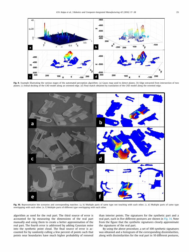
Fig. 9. Example illustrating the various stages of the automated perception algorithm: (a) Gauss map used to detect planes. (b) Edge extracted from intersection of twoplanes. (c) Initial docking of the CAD model along an oriented edge. (d) Final match obtained by translation of the CAD model along the oriented edge.
Fig. 10. Representative bin scenarios and corresponding matches: (a, b) Multiple parts of same type not touching with each other. (c, d) Multiple parts of same typeoverlapping with each other. (e, f) Multiple parts of different type overlapping with each other.
K.N. Kaipa et al. / Robotics and Computer-Integrated Manufacturing 42 (2016) 17–38 25
algorithm as used for the real part. The third source of error isaccounted for by measuring the dimensions of the real partmanually and using them to create a better approximation of thereal part. The fourth error is addressed by adding Gaussian noiseinto the synthetic point cloud. The final source of error is ac-counted for by randomly culling a few percent of points such thatpoints near boundaries have much higher probability of removal
than interior points. The signatures for the synthetic part and areal part, each in five different postures are shown in Fig. 14. Notefrom the figure that the synthetic signatures closely approximatethe signatures of the real part.
By using the above procedure, a set of 100 synthetic signatureswas obtained and a histogram of the corresponding dissimilarities,along with dissimilarities for the real part in 10 different postures,
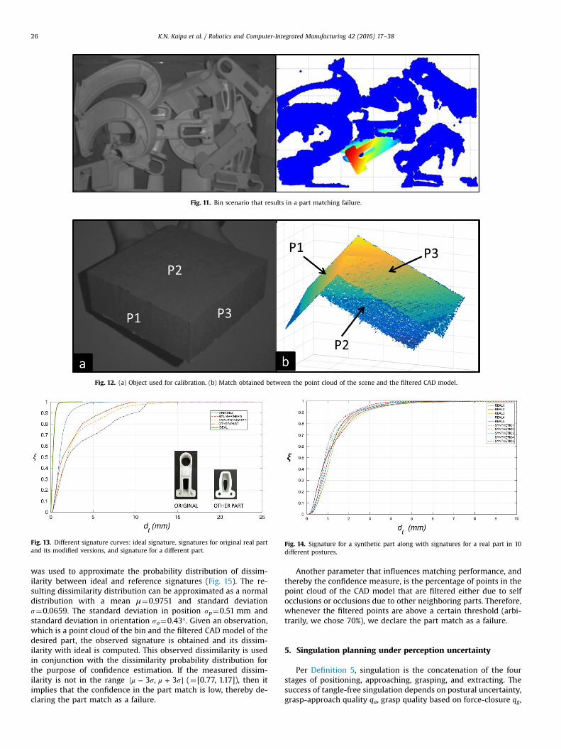
Fig. 11. Bin scenario that results in a part matching failure.
Fig. 12. (a) Object used for calibration. (b) Match obtained between the point cloud of the scene and the filtered CAD model.
Fig. 13. Different signature curves: ideal signature, signatures for original real partand its modified versions, and signature for a different part.
Fig. 14. Signature for a synthetic part along with signatures for a real part in 10different postures.
K.N. Kaipa et al. / Robotics and Computer-Integrated Manufacturing 42 (2016) 17–3826
was used to approximate the probability distribution of dissim-ilarity between ideal and reference signatures (Fig. 15). The re-sulting dissimilarity distribution can be approximated as a normaldistribution with a mean μ¼0.9751 and standard deviations¼0.0659. The standard deviation in position sp¼0.51 mm andstandard deviation in orientation so¼0.43°. Given an observation,which is a point cloud of the bin and the filtered CAD model of thedesired part, the observed signature is obtained and its dissim-ilarity with ideal is computed. This observed dissimilarity is usedin conjunction with the dissimilarity probability distribution forthe purpose of confidence estimation. If the measured dissim-ilarity is not in the range μ σ μ σ[ − + ]3 , 3 (¼[0.77, 1.17]), then itimplies that the confidence in the part match is low, thereby de-claring the part match as a failure.
Another parameter that influences matching performance, andthereby the confidence measure, is the percentage of points in thepoint cloud of the CAD model that are filtered either due to selfocclusions or occlusions due to other neighboring parts. Therefore,whenever the filtered points are above a certain threshold (arbi-trarily, we chose 70%), we declare the part match as a failure.
5. Singulation planning under perception uncertainty
Per Definition 5, singulation is the concatenation of the fourstages of positioning, approaching, grasping, and extracting. Thesuccess of tangle-free singulation depends on postural uncertainty,grasp-approach quality qa, grasp quality based on force-closure qg,

Fig. 15. Probability distribution of dissimilarity approximated as a normal dis-tribution with mean μ¼0.9751 and standard deviation s¼0.0659 based on thehistogram of dissimilarities.
K.N. Kaipa et al. / Robotics and Computer-Integrated Manufacturing 42 (2016) 17–38 27
and whether the part is tangle-free during singulation or not.Accordingly, we present a method that incorporates all the abovefactors to generate and evaluate singulation plans. In particular,each singulation plan is evaluated by estimating the over allprobability of successful tangle-free singulation
σ ρ ε℘( | ℓ̂ )( ) ( ) ( ) ( )s p , , , ,ij
i
j
ij
ij for each part instance ∈( )pi
jv. Fig. 16 shows
the overall system architecture used for plan generation andevaluation.
Fig. 16. Singulation pla
5.1. Plan generation
Each singulation plan is constructed by using four key postures:initial approach posture, pre-grasp posture, grasp posture, andextraction posture. Intermediate waypoints are generated throughlinear interpolation between neighboring postures. Note that onlythe position of the gripper changes during motion through thewaypoints, while its orientation remains the same. However, weallow orientation changes at the transition between two postures.Between pre-grasp and grasp, the location of the gripper remainsconstant, and the separation between the fingers decreases untilthe part is grasped. The orientation of the gripper depends on agrasping strategy for the part which is computed offline.
5.1.1. Offline computation of grasp strategiesWe use the popular force-closure quality metric [41] to evalu-
ate the grasp candidates. For each contact point, following[42,68,69], we verify if it satisfies a force-closure constraint. Con-sider two points a and b where the two fingers make contact withthe part's surface. The grasp at the contact pair is said to satisfy theforce-closure constraint if each point lies in the friction cone of theother point (Fig. 17(a)). The friction cone at each point is orientedabout the inward normal making a semi-angle μ( )−tan 1 , where μ isthe coefficient of friction. Now, we compute the grasp quality asthe number of points that satisfy force-closure divided by the totalnumber of points that project onto the finger surface.
For a particular grasp configuration, the pair of points wherethe center-axis of the gripper (along the pinching direction)
nning architecture.

Fig. 17. (a) Friction cone illustration. (b) A representative grasp configurationwhere points with black normals are not in contact with the gripper finger-pads, red ones makecontact but do not satisfy friction-cone property, and green ones are both in contact with gripper and stable grasps based on friction-cone concept described below. (c) Top20 grasp postures displayed on the CAD model of a given part. Grasps are sampled randomly and those which have non-zero grasp quality are plotted by depicting thecorresponding contact pairs. Green grasps represent the top 20 grasp qualities. The rest are represented as red. The size of the line segment is proportional to the quality ofeach grasp. (For interpretation of the references to color in this figure caption, the reader is referred to the web version of this paper.)
Fig. 18. Mixed-bins used in the experiments.
K.N. Kaipa et al. / Robotics and Computer-Integrated Manufacturing 42 (2016) 17–3828
intersects the part's surface is uniquely determined (Fig. 17(b)).Therefore, we can represent each grasp candidate by such pointpairs. Fig. 17(c) shows the grasp quality of the best 20 grasp pairsevaluated using the above method for an industrial part. Sampledpoint clouds are generated for the CAD models of the part and thegripper and used in the grasp quality computations. In the figure,the length of each line segment at a grasp point is proportional tothe corresponding grasp quality of that grasp pair.
5.1.2. Sampling based plannerWe use a sampling based planner that generates several ran-
dom plans. The initial approach posture is sampled at a safe heightfrom the bin and in a small region around a nominal posture thatcorresponds to the grasp candidate that is ranked best by theabove grasp quality metric. The pre-grasp posture is sampled in asmall region around the estimated posture of the target part. The
extraction posture is uniformly sampled at a safe height from thebin.
A Monte Carlo simulator evaluates each sampled plan by com-puting its probability of failure. The point cloud obtained from the3D sensor is split into two: one consisting of only the points in thebin, excluding the part to be picked, and the other point cloudconsisting of those points of the part that were captured by the 3Dcamera. The simulation scene involves the gripper, part CAD model,point cloud of the bin excluding the part, and the point cloud of thepart. The CAD models of the part and gripper are also converted tosampled point clouds before adding them to the scene.
Each simulation run works in the following way. Given that anautomated perception system provides an estimate of the pose of
target part ℓ̂( )i
jwith an error that follows a Gaussian distribution
σ( )( )0, ij , this is simulated by placing a CAD model of the part at

Fig. 19. Snapshots from an animation of a successful singulation plan. (a–c) Approach. (d–f) Pre-grasp to grasp. (g–i) Extraction.
Fig. 20. Snapshots from an animation of a failed singulation plan.
K.N. Kaipa et al. / Robotics and Computer-Integrated Manufacturing 42 (2016) 17–38 29
the estimated posture and shifting it by a value drawn from theabove distribution of pose-error. Now, a candidate plan is evaluatedby moving the gripper through the way-points, while checking for acollision at each way-point. The Point Cloud Library is used in Cþþto check for collisions. A collision is said to occur between two pointclouds when the minimum clearance between them falls below acertain threshold. If the way-point belongs to approach phase, thencollision is checked between gripper and the entire scene. If theway-point belongs to the grasping phase, then collision is checked
between gripper and the bin excluding part. If the way-point be-longs to the extraction phase, then collision is checked betweengripper and the bin excluding part, as well as between part and therest of the bin. These collision check conditions ensure that weachieve tangle-free singulation of the part. If a collision is returnedfor at least one way-point during a trial, then that trial is classified asa failure. If there are m such failure runs out of a total of n runs, thenthe probability of failure for the specified plan is m
n. The plan which
minimizes the probability of failure is chosen as the execution plan.

Fig. 21. Graph of average clearance as a function of step number for plans withvarying probabilities of failure.
Fig. 22. Graph of singulation success rate as a function of increasing perceptionuncertainty.
Fig. 24. The two types of deviation considered in the initial grasped state.
K.N. Kaipa et al. / Robotics and Computer-Integrated Manufacturing 42 (2016) 17–3830
5.2. Characterization of influence of perception uncertainty on sin-gulation plans
We first report results from illustrative experiments to showthe working of the sampling based plan generation and MonteCarlo-based plan evaluation. Bin 3 in Fig. 18 is used in these ex-periments. We use the same part (Fig. 8(a)) that was used inSection 4. Simulations were performed to compute failure prob-abilities Pf of different plans generated by the planner. Fig. 19shows snapshots from an animation of a sample Monte Carlo trialshowing different stages of a successful singulation plan. Fig. 20shows snapshots from an animation resulting in a failed singula-tion plan where gripper collides with the part to be singulatedduring approach.
Fig. 23. Robot using the pose estimated by the sys
It took 0.5 s to compute each trial. The computer running thesimulations consisted of Intel Core i7 2600 @ 3.4 GHz CPU and8-GB Dual-Channel DDR3 RAM memory. For each plan, a set of 100trials was simulated with a position uncertainty of 2 mm and or-ientation uncertainty of 4° in each axis, added into the estimated6D posture of the target part in each trial. Fig. 21 shows the graphof average clearance as a function of step number (1–5 Approach,6–10 Pre-grasp to Grasp, 11–15 Extraction) for five sampled planswith varying probabilities of failure. When the extraction locationwas directly above the estimated location of the target part, Pf¼1(“□”-marked curve). This was due to collision with a neighboringpart in the bin during extraction in every trial. But as the extrac-tion point was moved away from this location, Pf¼0 (“o”-markedcurve). Whenever the average minimum clearance dips below athreshold of E3 mm, we flag the state as collision and the plan isaborted. The clearance values after this point for each plan are onlyaveraged over the trials that have been reported as success by thesimulator. For another plan with Pf¼1 (“⋆”-marked curve), some ofthe trials failed during approach and the remaining during ex-traction at step 12. For the plan with Pf¼0.86 (“⋄”-marked curve,most of the trials failed indicating that it was a bad plan for thecurrent uncertainty model. The plan with Pf¼0 is representative ofan ideal plan for this uncertainty model. At every step in the plan,the average minimum clearance is safely above the threshold va-lue. For the plan with Pf¼0.166 (“▵”-marked curve), some of the
tem to proceed with the part singulation task.

Fig. 25. Five sample cases illustrating different initial grasp states and corresponding postures of the part after dropped off by the robot.
Fig. 26. Average positional error after direct drop off with varying uncertainties in the initial grasped posture.
K.N. Kaipa et al. / Robotics and Computer-Integrated Manufacturing 42 (2016) 17–38 31
trials failed due to collision during approach as a result of un-certainty in pose estimation.
Next, we analyzed how the probability of success of a suc-cessful plan degrades with increasing uncertainty introduced intothe estimated posture of the part. We considered standard de-viation increments of 2 mm in position along each axis and a fixedstandard deviation of 4° about each orientation axis. Note that theperception uncertainty levels (0.51 mm in position and 0.43° inorientation) found in Section 4 are well within the uncertaintyvalues considered for analyzing the singulation plans. We con-ducted this experiment for four bin samples and one plan withsuccess probability equal to one when uncertainty is zero. A set of100 Monte Carlo runs was used to compute the probability foreach uncertainty level. To accommodate uncertainty in the esti-mated part pose, maximum gripper pad separation was usedduring the approach phase to guarantee the encompassing of thepart. But in doing so, the fingers might collide with neighboring
parts resulting in a singulation failure. Fig. 22 shows the graph ofsuccess probability as a function of postural uncertainty for thefour bins shown in Fig. 18. The success probability of singulationplans starts degrading from a standard deviation of 9 mm in po-sitional error. Note that as the bin gets more cluttered in theneighborhood of the part to be picked, the degradation will beginat a smaller positional uncertainty.
The uncertainty information provided by the perception algo-rithm (from Section 4) is integrated into the above analysis tocompute success probability, which is used as a decision variableduring the singulation-plan execution phase. That is, for a givenuncertainty found from the perception result, if the successprobability, computed based on the above evaluation, is above τs(¼0.99), then robot proceeds with executing the singulation plan.Otherwise, either human intervention or randomize-bin commandis invoked based on the uncertainty level. For example, if theuncertainty is high, then human intervenes and adjusts the part

Fig. 27. Average orientation error after direct drop off with varying uncertainties in the initial grasped posture.
Fig. 28. Illustration of the fine-positioning subtask: (a,b) Moves for rotational error correction. (c) Moves for translational error correction.
K.N. Kaipa et al. / Robotics and Computer-Integrated Manufacturing 42 (2016) 17–3832
posture so that the robot can detect the part with higher con-fidence. However, if the uncertainty is low and still the plannerdoes not find a successful plan, then the part could be in a diffi-cult-to-reach posture. Hence, it is best to randomize the bin andrestart perception characterization. An example of a successfulsingulation plan implementation is shown in Fig. 23.
6. Correcting destination posture errors using sensorless fine-positioning
From the problem definition in Section 3, after each part∈( )pi
j has been singulated from the bin, it must be placed at a
destination posture ℓ( )ij within an expected postural accuracy Δℓ.
Factors like initial grasped postural uncertainty induced by per-ception uncertainty, positioning accuracy of the end-effector, andmomentum imparted to the part during drop-off degrade the
postural accuracy that can be achieved at the destination. Ac-cording to the second step in the high-level decision making in thehybrid cell (Section 3.3), a fine-positioning method is invoked tocorrect these postural errors.
6.1. Characterization of destination postural error in terms of initialgrasped posture uncertainty
We considered varying uncertainty in the initial grasped stateand examined the error in the destination posture after drop-off.To minimize the robot positional error, a sequence of two robotmoves, with coarse and fine motion-planning parameters, wereused before drop-off. (This corresponds to the second fine-posi-tioning strategy that is considered in the next subsection.) Stan-dard deviations of 5 mm, 8 mm, 10 mm, 12 mm, and 15 mm wereconsidered in the initial position along the vertical direction.Standard deviations of 3°, 5°, 8°, and 10° were considered in theorientation in the pinch axis. Deviations in position in the

Fig. 29. Snapshots from a video showing the execution of one sample plan that results in the positioning of the part within the accuracy limits: (a) Initial grasped state.(b) Gripper at drop-off location. (c) Part dropped off at final location. (d) Rotational error correction in the clockwise direction. (e) Rotational error correction in the counterclockwise direction. (f) Gripper moved to fine-positioning begin location. (g) Gripper rotated by 90°. (h) Gripper opened by fixed amount to correct translational error.(i) Gripper moved to neutral location.
Fig. 30. T-shaped tool used to push a flat surface.
K.N. Kaipa et al. / Robotics and Computer-Integrated Manufacturing 42 (2016) 17–38 33
horizontal plane and orientations in the approach and longitudinalaxes of the gripper were not considered, since any perceptionuncertainty in these directions are disambiguated when the part isgrasped. The two deviations considered are shown in Fig. 24. Fivesample cases illustrating different randomly initialized graspedstates and corresponding postures of the part after drop off by therobot are shown in Fig. 25. The average positional error and or-ientation error after direct drop off, with varying uncertainties inthe initial grasped posture, for 30 trials are shown in Figs. 26 and27, respectively.
6.2. Design of fine-positioning strategies
We describe an empirical methodology based on a re-presentative part (Fig. 8(a)) to select from a suite of fine-posi-tioning strategies that offer different tradeoffs between comple-tion time and postural accuracy at the destination. Once the part isdropped off at the destination, the basic fine-positioning taskconsists of the gripper applying a finite set of sliding forces andmoments on the part until its posture is within the desired pos-tural limits. We consider parts with the following properties:(1) When the part is lying on a flat surface in one of its stablepostures, two of the three orientation parameters are frozen (orbecome zero by using an appropriate coordinate frame assign-ment), leaving only one rotation parameter about the vertical axis.(2) When the part is in a stable posture, there exists at least onevertical flat face to which sliding forces can be applied. Given theabove assumptions on the part, there are two translational errorsand one rotational error associated with the posture of the part atthe goal location. The fine-positioning steps that achieve rotationaland translational error correction are illustrated in Fig. 28.
The specific algorithmic steps to achieve transport and fine-positioning are given below:
� Robot moves the grasped part from the singulation location to aposition vertically above the desired location. This is performedin two steps. Initially a coarse motion plan is used that trans-ports the part rapidly to the desired location, but with some

Fig. 31. Translation and orientation errors and execution times for five different regimes: (1) drop-off with coarse motion parameters, (2) drop-off with coarse and finemotion parameters, (3) drop-off with coarse and fine motion parameters and rotational corrective fine positioning moves, (4) drop-off with coarse and fine motion para-meters and translational corrective fine positioning moves, and (5) drop-off with coarse and fine motion parameters and both rotational and translational corrective finepositioning moves.
K.N. Kaipa et al. / Robotics and Computer-Integrated Manufacturing 42 (2016) 17–3834
positional error. Next, a fine motion plan is generated that re-duces the positional error at the drop-off location.
� Robot drops the part at the desired location. Considering theuncertainty in the grasp location, the object drop-off location isoffset by the maximum uncertainty value in the negative Y di-rection. This offset will ensure that the final location after drop-off will always have an error in the positive Y direction andhence the sliding would only be necessary in that direction.
� The grippers are closed with low gripping force to correct thetranslational error in the positive and negative X directions.
� A rotational error correction is applied by rotating the gripperby an appropriate amount about the vertical. Since the system issensor-less, the system is unaware if the error is in the clock-wise or in the counter clockwise direction. Thus the rotationalerror correction is performed in both directions. In all the cases,only one of the moves would be contributing to the error cor-rection. For example, assume that the robot's gripper first per-forms a clock-wise rotation, which is followed by a counter-clockwise rotation. Further assume that the angular offset of thepart is in the clock-wise direction. We can see that the partremains at rest during the first move, while the part's angularposition gets adjusted during the second move as shown inFig. 28(a).
� The gripper is lifted off and positioned behind the vertical faceof the part. This position is chosen by considering the maximumexpected positional error. This thereby ensures that the gripperis behind the part in all cases.
� The gripper moves a fixed distance in the positive Y directionthat is sufficient enough to nudge the part into its postural ac-curacy limits.
Fig. 29 shows snapshots from a video showing the execution ofone sample plan that results in the positioning of the part withinthe accuracy limits. Note from Fig. 29 that the sliding forces are
directly applied by the finger pads. A push tool with a matchedshape with respect to the part being pushed can be used to ensurebetter sliding movements. For example, a T-shaped tool is used inFig. 30 to push a flat surface. Similarly a convex tool front can beused for a part with a concave surface and so on.
Next, we characterized the performance of different fine-posi-tioning strategies We considered five fine-motion strategies:
1. Drop-off with coarse motion parameters.2. Drop-off with coarse and fine motion parameters.3. Drop-off with coarse and fine motion parameters and rotational
corrective fine positioning moves.4. Drop-off with coarse and fine motion parameters and transla-
tional corrective fine positioning moves.5. Drop-off with coarse and fine motion parameters and both ro-
tational and translational corrective fine positioning moves.
Fig. 31 shows the average translation errors, orientation errors,and execution times for each motion strategy across 10 trials. Weobserve that as more corrective moves are added, the accuracyimproves both in position and orientation, while the completiontime increases.
Now, we use the above results to select a fine-positioningstrategy. For example, from Figs. 26 and 27, an initial grasping un-certainty of 10 mm standard deviation in position and 10° standarddeviation in orientation leads to an average translation error ofabout 5 mm and an average orientation error of 3°. Now, fromFig. 31 if this meets the desired postural accuracy requirements, weuse the second fine-positioning strategy. Otherwise, if an accuracyof (2 mm, 2°) is required, we use the fifth fine-positioning strategy.
It took about 20 min to conduct the fine positioning experi-ments for this part. Whenever we have a new part, we use theabove experiments based methodology to select a fine-positioningstrategy based on the accuracy and completion time requirements.

Fig. 32. (a) Robot sending Skype call to a remotely operating human requesting for help. (b) 2D image of the bin and CAD model of the part to be identified. (c) User interfaceused by the remote human to resolve part recognition and pose estimation failures.
Fig. 33. Illustration of human identifying correspondences between edges in theimage with those in a CAD model.
K.N. Kaipa et al. / Robotics and Computer-Integrated Manufacturing 42 (2016) 17–38 35
7. Design of user interface to enable remote humaninterventions
We have developed a new user interface (Fig. 32) that allows aremote human to perform pose estimation in scenes with highclutter where the automated perception system may fail. Thesystem makes a Skype call to the remote human when help is
needed and sends three pieces of information: the raw cameraimage of the scene, the corresponding point cloud, and the CADmodel of the part to be picked.
The human operator selects features (edges) from the 2D imageand shows a correspondence in the CAD model (Fig. 33). The al-gorithm uses these features to estimate the part location and or-ientation in 3D and dock the CAD model at this pose. The humancan do minor adjustments to the pose using a joystick. The x and yinformation in the image space is transformed to point cloud co-ordinates using scaling and translation operations.
7.1. Accuracy/time tradeoff
There is a tradeoff between accuracy and time needed to ex-tract the data. Orientation accuracy impacts grasping performance.The accuracy needed to grasp a part successfully depends on itsshape complexity and its particular posture. This information ispre-determined for each part and conveyed to the human op-erator, who can stop the estimation process once a good enoughorientation accuracy is obtained. For this purpose, we placed asingle instance of the target part on a tripod and used a digital-inclination meter to set the orientation of the part at a knownposture. In one sample experiment, we used a nominal orientationof 30° about the longitudinal axis of the part and 35 degrees aboutthe lateral axis of the part. Next, we manually introduced 2-degree

Fig. 34. Average time taken (in seconds) by the human to complete the perception task for 10 trials in each regime across four different parts. Success rates of 100%, 80%, and100% were achieved in the first, second, and third regimes, respectively, for all the four parts.
Fig. 35. Comparison of average time taken (in seconds) by two users to complete the perception task for 10 trials in each regime for the white part.
K.N. Kaipa et al. / Robotics and Computer-Integrated Manufacturing 42 (2016) 17–3836
increments of perception error about each axis and observed itsimpact on grasping performance. For the part shown in Fig. 8(a),we noticed that the robot was able to successfully grasp up to anerror of 78° about the longitudinal axis. We noticed a highasymmetry about the lateral axis with successful grasping up to8° in the clockwise direction and only 2° in the counter clockwisedirection. This accuracy characteristic is made available to thehuman during training, which makes the human aware of howclosely to match, and hence decide how much time to spend onthe task.
7.2. Evaluation of the user interface
In these experiments, we considered complex bin exampleswhere the failure rate of the automated perception system wasmore than 50%. Fig. 32 shows the user interface used by the hu-man to perform part matching whenever the automated percep-tion system failed (Fig. 11). Fig. 32(c) shows the CAD modeldocking using the edge-selection method. The user interface pro-vides different functions that allow the human operator to achievethe part matching task. We conducted experiments to analyze theinfluence of different combinations of these features on both thetime taken to solve the problem and the overall success rate of the
singulation task. Accordingly, the effectiveness of the user inter-face was evaluated cross three experimental regimes:
1. Usage of only joystick to move the CAD model and dock it at anappropriate posture in the point cloud.
2. Usage of only the edge selection method to directly dock theCAD model.
3. Usage of the edge selection method to dock the CAD model, andsubsequently the joystick to do any fine adjustments ifnecessary.
We conducted 120 experimental trials. Each trial consisted ofthe human using one of the three methods to perform the partmatching task. Each trial was validated by sending the extractedpostural information to the robot and verifying whether or not therobot could singulate the specified part by using this information.We conducted ten trials for each regime and across four parts withdifferent geometries. We expect that this task will be performedby experts in real industrial settings. Therefore, all trials werecarried out by a well-trained user. The singulation success rate was80% in the second regime where only edge selection was used toregister the part. In the first and third regimes, the success ratewas 100%. Because of high success rates, 10 user trials per regime

K.N. Kaipa et al. / Robotics and Computer-Integrated Manufacturing 42 (2016) 17–38 37
was sufficient to validate the effectiveness of the user interface.The time taken (in seconds) by the human to complete the per-ception task over ten trials in each regime for all the four parts isshown in Fig. 34. Similar performance was observed across theparts for all the regimes. The edge-selection only took the leasttime for all the parts, but with some failure rate. Therefore, thethird regime that ranked second in terms of time, and with 100%success rate was chosen as the best solution.
In the third regime, the user spends about 10 s in edge selectionand subsequently about 25 s using the joystick to improve theestimated posture. Note that about 80% success rate can be ex-pected with only edge selection (from second regime). This in-formation can be exploited by the user to reduce the time spent inusing joystick to achieve a level of accuracy, which may beredundant.
Next, we tested the trainability of the interface. For this pur-pose, we trained a second user and conducted ten trials for thewhite part to compare the user's performance with that of the firstuser in all the three regimes. To have a common benchmark, thesame data used by the first user was presented to the second user.The comparison was only limited to the part-matching task inthese experiments, since the same bin settings were no longeravailable to proceed with the singulation task. Instead, differencein transformations was computed and used as a comparison me-tric. Fig. 35 shows the comparison of time taken by the two usersto complete the perception task. The second user took an averageof 36.7 s to complete the perception task for the white part, in thethird regime, which is very close to that of the first user. Similarperformance was observed in first and second regimes.
8. Conclusions
We presented an approach that treats coping with uncertaintyas a key step to handle failures and enhance performance in ro-botic unstructured bin-picking. The principal contributions in thepaper include:
1. A method to characterize uncertainty in pose estimation of apart match found by using an automated perception system.
2. A mechanism for the rationalized basis to detect failures andinvoke human interventions.
3. A new user interface that allows the remote human to providedistinguishing cues to reduce uncertainty in part pose esti-mates. This also enables part detection.
4. A singulation planner that incorporates uncertainty into planevaluation.
5. A fine positioning planner for correcting errors in destinationpart posture.
In our previous work, we have developed other modules in-cluding an ontology for task partitioning in human–robot colla-boration for kitting operations [70], resolving occlusions in roboticbin-picking [71], sequence planning for complex assemblies [72],instruction generation for human operations [73], bimanual ro-botic cleaning [74,75], and ensuring human safety [76]. Futurework consists of investigating how to integrate these modules todevelop hybrid work cells, where humans and robots collaborateto carry out non-repetitive industrial tasks. Currently, we used asingle-human–single-robot model. We would like to extend this toa single-human–multi-robot model, where a single human is re-motely bailing out multiple robots that may be stationed either atthe same work cell or different work cells. An interesting futureresearch direction lies in exploring whether the robot can learn,on-the-fly, as more information becomes available from the mis-takes made and the corresponding human interventions. Other
future works include exploring alternative sensor modalities,handling of heavy parts with more complex geometries, andsensor-based fine-positioning strategies.
Acknowledgments
This work is supported in part by National Science FoundationGrants #1200087 and #1527220 and National Institute of Stan-dards and Technology Cooperative Agreement #70NANB15H250.Opinions expressed are those of the authors and do not necessarilyreflect opinions of the sponsors.
References
[1] C. Schlenoff, Z. Kootbally, A. Pietromartire, M. Franaszek, S. Foufou, Intentionrecognition in manufacturing applications, Robot. Comput.-Integr. Manuf. 33(2015) 29–41, Special Issue on Knowledge Driven Robotics and Manufacturing.
[2] S. Balakirsky, Z. Kootbally, C. Schlenoff, T. Kramer, S.K. Gupta, An industrialrobotic knowledge representation for kit building applications, in: Proceedingsof IEEE/RSJ International Conference on Intelligent Robots and Systems, Oc-tober 2012, pp. 1365–1370.
[3] Z. Kootbally, C. Schlenoff, C. Lawler, T. Kramer, S. Gupta, Towards robust as-sembly with knowledge representation for the planning domain definitionlanguage (pddl), Robot. Comput.-Integr. Manuf. 33 (2015) 42–55, Special Issueon Knowledge Driven Robotics and Manufacturing.
[4] M.-Y. Liu, O. Tuzel, A. Veeraraghavan, Y. Taguchi, T.K. Marks, R. Chellappa, Fastobject localization and pose estimation in heavy clutter for robotic bin picking,Int. J. Robot. Res. 31 (8) (2012) 951–973.
[5] J.A. Marvel, K. Saidi, R. Eastman, T. Hong, G. Cheok, E. Messina, Technologyreadiness levels for randomized bin picking, in: Proceedings of the Workshopon Performance Metrics for Intelligent Systems, PerMIS, New York, NY, USA,ACM, 2012, pp. 109–113.
[6] H. Golnabi, A. Asadpour, Design and application of industrial machine visionsystems, Robot. Comput.-Integr. Manuf. 23 (6) (2007) 630–637.
[7] A.M. Pinto, L.F. Rocha, A.P. Moreira, Object recognition using laser range finderand machine learning techniques, Robot. Comput.-Integr. Manuf. 29 (1) (2013)12–22.
[8] A. Pochyly, T. Kubela, V. Singule, P. Cihak, 3d vision systems for industrial bin-picking applications, in: 15th International Symposium on MECHATRONIKA,December 2012, pp. 1–6.
[9] K. Bohringer, B. Donald, L. Kavraki, F. Lamiraux, Part orientation with one ortwo stable equilibria using programmable force fields, IEEE Trans. Robot. Au-tom. 16 (April) (2000) 157–170.
[10] K.N. Kaipa, A.S. Kankanhalli-Nagendra, S.K. Gupta, Toward estimating taskexecution confidence for robotic bin-picking applications, in: AAAI Fall Sym-posium: Self-Confidence in Autonomous Systems, 2015.
[11] K.N. Kaipa, S.S. Thevendria-Karthic, S. Shriyam, A.M. Kabir, J.D. Langsfeld, S.K.Gupta, Resolving automated perception system failures in bin-picking tasksusing assistance from remote human operators, in: Proceedings of IEEE In-ternational Conference on Automation Science and Engineering, August 2015.
[12] K.N. Kaipa, S. Shriyam, N.B. Kumbla, S.K. Gupta, Automated plan generation forrobotic singulation from mixed bins, in: IROS Workshop on Task Planning forIntelligent Robots in Service and Manufacturing, 2015.
[13] K.N. Kaipa, N.B. Kumbla, S.K. Gupta, Characterizing performance of sensorlessfine positioning moves in the presence of grasping position uncertainty, in:IROS Workshop on Task Planning for Intelligent Robots in Service and Man-ufacturing, 2015.
[14] G. Sansoni, P. Bellandi, F. Leoni, F. Docchio, Optoranger: a 3d pattern matchingmethod for bin picking applications, Opt. Lasers Eng. 54 (2014) 222–231.
[15] H.-Y. Kuo, H.-R. Su, S.-H. Lai, C.-C. Wu, 3d object detection and pose estimationfrom depth image for robotic bin picking, in: Proceedings of IEEE InternationalConference on Automation Science and Engineering (CASE), 2014, pp. 1264–1269.
[16] D. Holz, M. Nieuwenhuisen, D. Droeschel, J. Stückler, A. Berner, J. Li, R. Klein, S.Behnke, Active recognition and manipulation for mobile robot bin picking, in:Gearing Up and Accelerating Cross-fertilization between Academic and In-dustrial Robotics Research in Europe, Springer, 2014, pp. 133–153.
[17] M. Nieuwenhuisen, D. Droeschel, D. Holz, J. Stuckler, A. Berner, J. Li, R. Klein, S.Behnke, Mobile bin picking with an anthropomorphic service robot, in: Pro-ceedings of IEEE International Conference on Robotics and Automation (ICRA),2013, pp. 2327–2334.
[18] A. Pretto, S. Tonello, E. Menegatti, Flexible 3d localization of planar objects forindustrial bin-picking with monocamera vision system, in: Proceedings ofIEEE International Conference on Automation Science and Engineering (CASE),2013, pp. 168–175.
[19] J.J. Rodrigues, J.-S. Kim, M. Furukawa, J. Xavier, P. Aguiar, T. Kanade, 6d poseestimation of textureless shiny objects using random ferns for bin-picking, in:Proceedings of IEEE/RSJ International Conference on Intelligent Robots andSystems (IROS), 2012, pp. 3334–3341.

K.N. Kaipa et al. / Robotics and Computer-Integrated Manufacturing 42 (2016) 17–3838
[20] J.-K. Oh, S. Lee, C.-H. Lee, Stereo vision based automation for a bin-pickingsolution, Int. J. Control Autom. Syst. 10 (2) (2012) 362–373.
[21] S. Lee, J. Kim, M. Lee, K. Yoo, L.G. Barajas, R. Menassa, 3d visual perceptionsystem for bin picking in automotive sub-assembly automation, in: Proceed-ings of IEEE International Conference on Automation Science and Engineering(CASE), 2012, pp. 706–713.
[22] D. Buchholz, S. Winkelbach, F.M. Wahl, Ransam for industrial bin-picking, in:Proceedings of 41st International Symposium on Robotics (ISR) and 6th Ger-man Conference on Robotics (ROBOTIK), 2010, pp. 1–6.
[23] K. Boehnke, Object localization in range data for robotic bin picking, in: Pro-ceedings of IEEE International Conference on Automation Science and En-gineering, CASE, 2007, pp. 572–577.
[24] F. Boughorbel, Y. Zhang, S. Kang, U. Chidambaram, B. Abidi, A. Koschan,M. Abidi, Laser ranging and video imaging for bin picking, Assembly Autom.23 (1) (2003) 53–59.
[25] B.K. Horn, K. Ikeuchi, Picking Parts Out of a Bin, Tech. Report, MassachussettsInstitute of Technology, 1982.
[26] Y. Domae, H. Okuda, Y. Taguchi, K. Sumi, T. Hirai, Fast graspability evaluationon single depth maps for bin picking with general grippers, in: Proceedings ofIEEE International Conference on Robotics and Automation (ICRA), 2014, pp.1997–2004.
[27] D. Buchholz, D. Kubus, I. Weidauer, A. Scholz, F.M. Wahl, Combining visual andinertial features for efficient grasping and bin-picking, in: Proceedings of IEEEInternational Conference on Robotics and Automation (ICRA), 2014, pp. 875–882.
[28] D.C. Dupuis, S. Léonard, M.A. Baumann, E.A. Croft, J.J. Little, Two-fingeredgrasp planning for randomized bin-picking, in: Proceedings of the Robotics:Science and Systems Manipulation Workshop-Intelligence in Human En-vironments, 2008.
[29] L.-P. Ellekilde, H.G. Petersen, Motion planning efficient trajectories for in-dustrial bin-picking, Int. J. Robot. Res. 32 (9–10) (2013) 991–1004.
[30] D. Buchholz, M. Futterlieb, S. Winkelbach, F.M. Wahl, Efficient bin-picking andgrasp planning based on depth data, in: Proceedings of IEEE InternationalConference on Robotics and Automation (ICRA), 2013, pp. 3245–3250.
[31] S. Kristensen, S. Estable, M. Kossow, R. Brösel, Bin-picking with a solid staterange camera, Robot. Auton. Syst. 35 (3–4) (2001) 143–151.
[32] K. Harada, K. Nagata, T. Tsuji, N. Yamanobe, A. Nakamura, Y. Kawai, Probabil-istic approach for object bin picking approximated by cylinders, in: Proceed-ings of IEEE International Conference on Robotics and Automation (ICRA),2013, pp. 3742–3747.
[33] C. Papazov, S. Haddadin, S. Parusel, K. Krieger, D. Burschka, Rigid 3d geometrymatching for grasping of known objects in cluttered scenes, Int. J. Robot. Res.(2012), DOI:10.1177/0278364911436019.
[34] S. Fuchs, S. Haddadin, M. Keller, S. Parusel, A. Kolb, M. Suppa, Cooperative bin-picking with time-of-flight camera and impedance controlled dlr lightweightrobot iii, in: Proceedings of IEEE/RSJ International Conference on IntelligentRobots and Systems, 2010, pp. 4862–4867.
[35] L.-P. Ellekilde, J. Jorgensen, D. Kraft, N. Kruger, J. Piater, H.G. Petersen, et al.,Applying a learning framework for improving success rates in industrial binpicking, in: Proceedings of IEEE/RSJ International Conference on IntelligentRobots and Systems (IROS), 2012, pp. 1637–1643.
[36] A. Pronobis, B. Caputo, Confidence-based cue integration for visual place re-cognition, in: IEEE/RSJ International Conference on Intelligent Robots andSystems, 2007, pp. 2394–2401.
[37] A. Sahbani, S. El-Khoury, P. Bidaud, An overview of 3d object grasp synthesisalgorithms, Robot. Auton. Syst. 60 (3) (2012) 326–336.
[38] A. Bicchi, V. Kumar, Robotic grasping and contact: a review, in: Proceedings ofIEEE/RSJ International Conference on Robotics and Automation, vol. 1, 2000,pp. 348–353.
[39] J. Bohg, A. Morales, T. Asfour, D. Kragic, Data-driven grasp synthesis—a survey,IEEE Trans. Robot. 30 (April) (2014) 289–309.
[40] A. Miller, P. Allen, Graspit! a versatile simulator for robotic grasping, IEEERobot. Autom. Mag. 11 (December) (2004) 110–122.
[41] C. Ferrari, J. Canny, Planning optimal grasps, in: Proceedings of IEEE Interna-tional Conference on Robotics and Automation, vol. 3, May 1992, pp. 2290–2295.
[42] V.-D. Nguyen, Constructing force-closure grasps, Int. J. Robot. Res. 7 (3) (1988)3–16.
[43] M. Roa, R. Suarez, Computation of independent contact regions for grasping3-d objects, IEEE Trans. Robot. 25 (August) (2009) 839–850.
[44] Y. Zheng, W.-H. Qian, Coping with the grasping uncertainties in force-closureanalysis, Int. J. Robot. Res. 24 (4) (2005) 311–327.
[45] D. Berenson, S. Srinivasa, J. Kuffner, Addressing pose uncertainty in manip-ulation planning using task space regions, in: Proceedings of IEEE/RSJ Inter-national Conference on Intelligent Robots and Systems, October 2009, pp.1419–1425.
[46] J. Weisz, P. Allen, Pose error robust grasping from contact wrench space me-trics, in: Proceedings of IEEE International Conference on Robotics and Auto-mation, May 2012, pp. 557–562.
[47] B. Kehoe, D. Berenson, K. Goldberg, Toward cloud-based grasping with un-certainty in shape: estimating lower bounds on achieving force closure withzero-slip push grasps, in: Proceedings of IEEE International Conference on
Robotics and Automation, May 2012, pp. 576–583.[48] J. Glover, D. Rus, and N. Roy, Probabilistic models of object geometry for grasp
planning, in: Proceedings of Robotics: Science and Systems, 2008.[49] K. Goldberg, M.T. Mason, Bayesian grasping, in: Proceedings of IEEE Interna-
tional Conference on Robotics and Automation, vol. 2, May 1990, pp. 1264–1269.
[50] K. Hsiao, M. Ciocarlie, P. Brook, Bayesian grasp planning, in: ICRAWorkshop onMobile Manipulation: Integrating Perception and Manipulation, 2011.
[51] M. Erdmann, M.T. Mason, An exploration of sensorless manipulation, IEEE J.Robot. Autom. 4 (August) (1988) 369–379.
[52] M. Erdmann, M. Mason, J. Vaněček, Mechanical parts orienting: the case of apolyhedron on a table, Algorithmica 10 (2–4) (1993) 226–247.
[53] S. Akella, W. Huang, K. Lynch, M.T. Mason, Sensorless parts orienting with aone-joint manipulator, in: Proceedings of IEEE International Conference onRobotics and Automation, vol. 3, April 1997, pp. 2383–2390.
[54] K. Goldberg, Orienting polygonal parts without sensors, Algorithmica 10 (2–4)(1993) 201–225.
[55] M. Erdmann, An exploration of nonprehensile two-palm manipulation, Int. J.Robot. Res. 17 (5) (1998) 485–503.
[56] M. Dogar, S. Srinivasa, Push-grasping with dexterous hands: mechanics and amethod, in: IEEE/RSJ International Conference on Intelligent Robots and Sys-tems (IROS), October 2010, pp. 2123–2130.
[57] S. Kristek, D. Shell, Orienting deformable polygonal parts without sensors, in:Proceedings of IEEE/RSJ International Conference on Intelligent Robots andSystems (IROS), October 2012, pp. 973–979.
[58] A. Holladay, J. Barry, L. Kaelbling, T. Lozano-Perez, Object placement as inversemotion planning, in: Proceedings of IEEE International Conference on Roboticsand Automation (ICRA), 2013, pp. 3715–3721.
[59] F. Panahi, A.F. van der Stappen, Bounding the locus of the center of mass for apart with shape variation, Comput. Geom. 47 (8) (2014) 847–855.
[60] Y. Bai, C. Liu, Dexterous manipulation using both palm and fingers, in: Pro-ceedings of IEEE International Conference on Robotics and Automation (ICRA),2014, pp. 1560–1565.
[61] F. Duan, J. Tan, J.G. Tong, R. Kato, T. Arai, Application of the assembly skilltransfer system in an actual cellular manufacturing system, IEEE Trans. Autom.Sci. Eng. 9 (1) (2012) 31–41.
[62] S. Takata, T. Hirano, Human and robot allocation method for hybrid assemblysystems, {CIRP} Annals—Manuf. Technol. 60 (1) (2011) 9–12.
[63] F. Chen, K. Sekiyama, H. Sasaki, J. Huang, B. Sun, T. Fukuda, Assembly strategymodeling and selection for human and robot coordinated cell assembly, in:Proceedings of IEEE/RSJ International Conference on Intelligent Robots andSystems (IROS), 2011, pp. 4670–4675.
[64] M. Morioka, S. Sakakibara, A new cell production assembly system with hu-man-robot cooperation, {CIRP} Annals—Manuf. Technol. 59 (1) (2010) 9–12.
[65] C. Weber, S. Hahmann, H. Hagen, Sharp feature detection in point clouds, in:Proceedings of Shape Modeling International Conference (SMI), 2010, pp. 175–186.
[66] K. Demarsin, D. Vanderstraeten, T. Volodine, D. Roose, Detection of closedsharp edges in point clouds using normal estimation and graph theory,Comput.-Aided Des. 39 (4) (2007) 276–283.
[67] S. Gumhold, X. Wang, R. Macleod, Feature extraction from point clouds, in:Proceedings of the 10th International Meshing Roundtable, 2001, pp. 293–305.
[68] B. Faverjon, J. Ponce, On computing two-finger force-closure grasps of curved2d objects, in: Proceedings of IEEE International Conference on Robotics andAutomation, 1991, pp. 424–429.
[69] A. Blake, A symmetry theory of planar grasp, Int. J. Robot. Res. 14 (5) (1995)425–444.
[70] A.G. Banerjee, A. Barnes, K.N. Kaipa, J. Liu, S. Shriyam, N. Shah, S.K. Gupta, Anontology to enable optimized task partitioning in human-robot collaborationfor warehouse kitting operations, in: Proceedings of SPIE, Next-GenerationRobotics II; and Machine Intelligence and Bio-inspired Computation: Theoryand Applications IX, 2015.
[71] K.N. Kaipa, S. Shriyam, G.S.K., Resolving occlusions through simple extractionmotions in robotic bin-picking, in: ASMEs 11th Manufacturing Science andEngineering Conference, June 2016.
[72] C. Morato, K.N. Kaipa, S.K. Gupta, Improving assembly precedence constraintgeneration by utilizing motion planning and part interaction clusters, Com-put.-Aided Des. 45 (11) (2013) 1349–1364.
[73] K.N. Kaipa, C. Morato, B. Zhao, S.K. Gupta, Instruction generation for assemblyoperations performed by humans, in: Proceedings of ASME InternationalDesign Engineering Technical Conferences and Computers and Information inEngineering Conference, 2012, pp. 1121–1130.
[74] A.M. Kabir, J.D. Langsfeld, C. Zhuang, K.K.N., G.S.K., Automated learning ofoperation parameters for robotic cleaning by mechanical scrubbing, in: ASMEs11th Manufacturing Science and Engineering Conference, June 2016.
[75] J.D. Langsfeld, A.M. Kabir, K.K.N., G.S.K., Online learning of part deformationmodels in robotic cleaning of compliant objects, in: ASMEs 11th Manu-facturing Science and Engineering Conference, June 2016.
[76] C. Morato, K.N. Kaipa, B. Zhao, S.K. Gupta, Toward safe human robot colla-boration by using multiple kinects based real-time human tracking, J. Comput.Inf. Sci. Eng. 14 (1) (2014).